EP3719265B1 - Rotating carbon piston ring seal - Google Patents
Rotating carbon piston ring seal Download PDFInfo
- Publication number
- EP3719265B1 EP3719265B1 EP20168032.9A EP20168032A EP3719265B1 EP 3719265 B1 EP3719265 B1 EP 3719265B1 EP 20168032 A EP20168032 A EP 20168032A EP 3719265 B1 EP3719265 B1 EP 3719265B1
- Authority
- EP
- European Patent Office
- Prior art keywords
- annular
- seal
- sections
- sealing surface
- radially
- Prior art date
- Legal status (The legal status is an assumption and is not a legal conclusion. Google has not performed a legal analysis and makes no representation as to the accuracy of the status listed.)
- Active
Links
- OKTJSMMVPCPJKN-UHFFFAOYSA-N Carbon Chemical compound [C] OKTJSMMVPCPJKN-UHFFFAOYSA-N 0.000 title 1
- 229910052799 carbon Inorganic materials 0.000 title 1
- 238000007789 sealing Methods 0.000 claims description 40
- 238000000034 method Methods 0.000 claims description 5
- 230000004044 response Effects 0.000 claims description 4
- 239000003575 carbonaceous material Substances 0.000 claims description 3
- 230000000712 assembly Effects 0.000 description 4
- 238000000429 assembly Methods 0.000 description 4
- 239000000463 material Substances 0.000 description 3
- 239000000446 fuel Substances 0.000 description 2
- 230000007480 spreading Effects 0.000 description 2
- 230000003068 static effect Effects 0.000 description 2
- 230000008901 benefit Effects 0.000 description 1
- 239000000919 ceramic Substances 0.000 description 1
- 239000011153 ceramic matrix composite Substances 0.000 description 1
- 230000008859 change Effects 0.000 description 1
- 238000002485 combustion reaction Methods 0.000 description 1
- 238000004891 communication Methods 0.000 description 1
- 239000002131 composite material Substances 0.000 description 1
- 230000006835 compression Effects 0.000 description 1
- 238000007906 compression Methods 0.000 description 1
- 229920001971 elastomer Polymers 0.000 description 1
- 239000000806 elastomer Substances 0.000 description 1
- 230000007246 mechanism Effects 0.000 description 1
- 229910052751 metal Inorganic materials 0.000 description 1
- 239000002184 metal Substances 0.000 description 1
- 150000002739 metals Chemical class 0.000 description 1
- 230000004048 modification Effects 0.000 description 1
- 238000012986 modification Methods 0.000 description 1
- 229910052755 nonmetal Inorganic materials 0.000 description 1
- 150000002843 nonmetals Chemical class 0.000 description 1
- 239000002861 polymer material Substances 0.000 description 1
- 230000001141 propulsive effect Effects 0.000 description 1
Images

Classifications
-
- F—MECHANICAL ENGINEERING; LIGHTING; HEATING; WEAPONS; BLASTING
- F01—MACHINES OR ENGINES IN GENERAL; ENGINE PLANTS IN GENERAL; STEAM ENGINES
- F01D—NON-POSITIVE DISPLACEMENT MACHINES OR ENGINES, e.g. STEAM TURBINES
- F01D11/00—Preventing or minimising internal leakage of working-fluid, e.g. between stages
- F01D11/005—Sealing means between non relatively rotating elements
-
- F—MECHANICAL ENGINEERING; LIGHTING; HEATING; WEAPONS; BLASTING
- F16—ENGINEERING ELEMENTS AND UNITS; GENERAL MEASURES FOR PRODUCING AND MAINTAINING EFFECTIVE FUNCTIONING OF MACHINES OR INSTALLATIONS; THERMAL INSULATION IN GENERAL
- F16J—PISTONS; CYLINDERS; SEALINGS
- F16J15/00—Sealings
- F16J15/16—Sealings between relatively-moving surfaces
- F16J15/32—Sealings between relatively-moving surfaces with elastic sealings, e.g. O-rings
- F16J15/3204—Sealings between relatively-moving surfaces with elastic sealings, e.g. O-rings with at least one lip
- F16J15/3208—Sealings between relatively-moving surfaces with elastic sealings, e.g. O-rings with at least one lip provided with tension elements, e.g. elastic rings
-
- F—MECHANICAL ENGINEERING; LIGHTING; HEATING; WEAPONS; BLASTING
- F16—ENGINEERING ELEMENTS AND UNITS; GENERAL MEASURES FOR PRODUCING AND MAINTAINING EFFECTIVE FUNCTIONING OF MACHINES OR INSTALLATIONS; THERMAL INSULATION IN GENERAL
- F16J—PISTONS; CYLINDERS; SEALINGS
- F16J15/00—Sealings
- F16J15/16—Sealings between relatively-moving surfaces
- F16J15/32—Sealings between relatively-moving surfaces with elastic sealings, e.g. O-rings
- F16J15/3204—Sealings between relatively-moving surfaces with elastic sealings, e.g. O-rings with at least one lip
- F16J15/3232—Sealings between relatively-moving surfaces with elastic sealings, e.g. O-rings with at least one lip having two or more lips
-
- F—MECHANICAL ENGINEERING; LIGHTING; HEATING; WEAPONS; BLASTING
- F16—ENGINEERING ELEMENTS AND UNITS; GENERAL MEASURES FOR PRODUCING AND MAINTAINING EFFECTIVE FUNCTIONING OF MACHINES OR INSTALLATIONS; THERMAL INSULATION IN GENERAL
- F16J—PISTONS; CYLINDERS; SEALINGS
- F16J15/00—Sealings
- F16J15/16—Sealings between relatively-moving surfaces
- F16J15/34—Sealings between relatively-moving surfaces with slip-ring pressed against a more or less radial face on one member
- F16J15/3464—Mounting of the seal
-
- F—MECHANICAL ENGINEERING; LIGHTING; HEATING; WEAPONS; BLASTING
- F01—MACHINES OR ENGINES IN GENERAL; ENGINE PLANTS IN GENERAL; STEAM ENGINES
- F01D—NON-POSITIVE DISPLACEMENT MACHINES OR ENGINES, e.g. STEAM TURBINES
- F01D11/00—Preventing or minimising internal leakage of working-fluid, e.g. between stages
- F01D11/02—Preventing or minimising internal leakage of working-fluid, e.g. between stages by non-contact sealings, e.g. of labyrinth type
- F01D11/025—Seal clearance control; Floating assembly; Adaptation means to differential thermal dilatations
-
- F—MECHANICAL ENGINEERING; LIGHTING; HEATING; WEAPONS; BLASTING
- F05—INDEXING SCHEMES RELATING TO ENGINES OR PUMPS IN VARIOUS SUBCLASSES OF CLASSES F01-F04
- F05D—INDEXING SCHEME FOR ASPECTS RELATING TO NON-POSITIVE-DISPLACEMENT MACHINES OR ENGINES, GAS-TURBINES OR JET-PROPULSION PLANTS
- F05D2220/00—Application
- F05D2220/30—Application in turbines
- F05D2220/32—Application in turbines in gas turbines
-
- F—MECHANICAL ENGINEERING; LIGHTING; HEATING; WEAPONS; BLASTING
- F05—INDEXING SCHEMES RELATING TO ENGINES OR PUMPS IN VARIOUS SUBCLASSES OF CLASSES F01-F04
- F05D—INDEXING SCHEME FOR ASPECTS RELATING TO NON-POSITIVE-DISPLACEMENT MACHINES OR ENGINES, GAS-TURBINES OR JET-PROPULSION PLANTS
- F05D2230/00—Manufacture
- F05D2230/60—Assembly methods
- F05D2230/64—Assembly methods using positioning or alignment devices for aligning or centring, e.g. pins
-
- F—MECHANICAL ENGINEERING; LIGHTING; HEATING; WEAPONS; BLASTING
- F05—INDEXING SCHEMES RELATING TO ENGINES OR PUMPS IN VARIOUS SUBCLASSES OF CLASSES F01-F04
- F05D—INDEXING SCHEME FOR ASPECTS RELATING TO NON-POSITIVE-DISPLACEMENT MACHINES OR ENGINES, GAS-TURBINES OR JET-PROPULSION PLANTS
- F05D2240/00—Components
- F05D2240/55—Seals
- F05D2240/58—Piston ring seals
-
- F—MECHANICAL ENGINEERING; LIGHTING; HEATING; WEAPONS; BLASTING
- F05—INDEXING SCHEMES RELATING TO ENGINES OR PUMPS IN VARIOUS SUBCLASSES OF CLASSES F01-F04
- F05D—INDEXING SCHEME FOR ASPECTS RELATING TO NON-POSITIVE-DISPLACEMENT MACHINES OR ENGINES, GAS-TURBINES OR JET-PROPULSION PLANTS
- F05D2260/00—Function
- F05D2260/30—Retaining components in desired mutual position
- F05D2260/38—Retaining components in desired mutual position by a spring, i.e. spring loaded or biased towards a certain position
-
- F—MECHANICAL ENGINEERING; LIGHTING; HEATING; WEAPONS; BLASTING
- F05—INDEXING SCHEMES RELATING TO ENGINES OR PUMPS IN VARIOUS SUBCLASSES OF CLASSES F01-F04
- F05D—INDEXING SCHEME FOR ASPECTS RELATING TO NON-POSITIVE-DISPLACEMENT MACHINES OR ENGINES, GAS-TURBINES OR JET-PROPULSION PLANTS
- F05D2300/00—Materials; Properties thereof
- F05D2300/20—Oxide or non-oxide ceramics
- F05D2300/22—Non-oxide ceramics
- F05D2300/224—Carbon, e.g. graphite
-
- F—MECHANICAL ENGINEERING; LIGHTING; HEATING; WEAPONS; BLASTING
- F16—ENGINEERING ELEMENTS AND UNITS; GENERAL MEASURES FOR PRODUCING AND MAINTAINING EFFECTIVE FUNCTIONING OF MACHINES OR INSTALLATIONS; THERMAL INSULATION IN GENERAL
- F16J—PISTONS; CYLINDERS; SEALINGS
- F16J15/00—Sealings
- F16J15/16—Sealings between relatively-moving surfaces
- F16J15/164—Sealings between relatively-moving surfaces the sealing action depending on movements; pressure difference, temperature or presence of leaking fluid
Definitions
- the present invention is related to a rotating seal assembly for sealing between co-rotating parts of a gas turbine engine, to a corresponding gas turbine engine assembly and to a method of assembling a rotating seal for a gas turbine engine.
- a gas turbine engine typically includes a fan section, a compressor section, a combustor section and a turbine section. Air entering the compressor section is compressed and delivered into the combustion section where it is mixed with fuel and ignited to generate a high-speed exhaust gas flow. The high-speed exhaust gas flow expands through the turbine section to drive the compressor and the fan section.
- the compressor section typically includes low and high pressure compressors, and the turbine section includes low and high pressure turbines.
- Seals are provided throughout the engine to control airflows. Some seals are disposed between relative rotating parts and are designed to accommodate wear. Other seals are disposed between parts that may rotate, but not relative to each other. Even without relative rotation, wear may occur due to vibrational, or other relative movement that occurs during engine operation.
- Turbine engine manufacturers continually seek improvements to engine performance including improvements to thermal and propulsive efficiencies.
- EP 2,453,150 A1 discloses a seal assembly.
- US 2015/050130 A1 discloses a sealing device between two axisymmetric coaxial parts.
- EP 2,562,364 A1 discloses a rotating turbomachine seal.
- EP 2,803,825 A1 discloses a seal structure for a rotary machine, and a gas turbine engine with the same.
- EP 3,611,348 A1 discloses a gas turbine engine seal ring assembly.
- US 2019/323370 A1 discloses a segmented piston seal system.
- a rotating seal assembly for sealing between co-rotating parts of a gas turbine engine as claimed in claim 1.
- the radially-outer-facing sealing surface comprises a sealing surface on axial sides of the slot.
- the at least two annular sections includes multiple annular sections each including an overlapping interface between adjacent ends.
- each of the at least two annular sections comprises a carbon material.
- the present invention also extends to a gas turbine engine assembly as claimed in claim 6.
- the shaft includes a section of increased diameter with the annular groove positioned within the increased diameter.
- the radial inner surface includes an axially extending portion.
- the seal prevents hot airflow from moving forward past the seal.
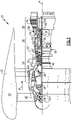
- FIG. 1 schematically illustrates a gas turbine engine 20.
- the gas turbine engine 20 is disclosed herein as a two-spool turbofan that generally incorporates a fan section 22, a compressor section 24, a combustor section 26 and a turbine section 28.
- the fan section 22 drives air along a bypass flow path B in a bypass duct defined within a nacelle 18, and also drives air along a core flow path C for compression and communication into the combustor section 26 then expansion through the turbine section 28.
- FIG. 1 schematic
- the exemplary engine 20 generally includes a low speed spool 30 and a high speed spool 32 mounted for rotation about an engine central longitudinal axis A relative to an engine static structure 36 via several bearing systems 38. It should be understood that the various bearing systems 38 may alternatively or additionally be provided at different locations, and the location of bearing systems 38 may be varied as appropriate to the application.
- the low speed spool 30 generally includes an inner shaft 40 that interconnects, a first (or low) pressure compressor 44 and a first (or low) pressure turbine 46.
- the inner shaft 40 is connected to a fan 42 through a speed change mechanism, which in exemplary gas turbine engine 20 is illustrated as a geared architecture 48 to drive the fan 42 at a lower speed than the low speed spool 30.
- the high speed spool 32 includes an outer shaft 50 that interconnects a second (or high) pressure compressor 52 and a second (or high) pressure turbine 54.
- a combustor 56 is arranged in exemplary gas turbine 20 between the high pressure compressor 52 and the high pressure turbine 54.
- a mid-turbine frame 58 of the engine static structure 36 may be arranged generally between the high pressure turbine 54 and the low pressure turbine 46.
- the mid-turbine frame 58 further supports bearing systems 38 in the turbine section 28.
- the inner shaft 40 and the outer shaft 50 are concentric and rotate via bearing systems 38 about the engine central longitudinal axis A which is colline
- the core airflow is compressed by the low pressure compressor 44 then the high pressure compressor 52, mixed and burned with fuel in the combustor 56, then expanded over the high pressure turbine 54 and low pressure turbine 46.
- the mid-turbine frame 58 includes airfoils 60 which are in the core airflow path C.
- the turbines 46, 54 rotationally drive the respective low speed spool 30 and high speed spool 32 in response to the expansion.
- gear system 48 may be located aft of the low pressure compressor, or aft of the combustor section 26 or even aft of turbine section 28, and fan 42 may be positioned forward or aft of the location of gear system 48.
- a seal assembly 62 is provided to contain airflow produced in aft compartments of the engine 20.
- the seal assembly 62 prevents hot airflow from accessing cooler parts of the engine 20.
- the seal assembly 62 is disposed within the high pressure compressor 52.
- the high pressure compressor 52 is an eight stage compressor with forward stages 65 forward of the seal assembly 62 and aft stages 67 aft of the seal assembly 62.
- the example seal is disclosed within an eight-stage high pressure compressor 52, other compressor configurations would benefit from this disclosure and are within the contemplated scope of this disclosure.
- the example seal assembly 62 may be utilized in other locations of the engine 20 for containing and controlling airflow.
- example seal assembly 62 is disclosed by way of example with regard to use in a gas turbine engine, the example seal assembly may be used between any two co-rotating parts such as maybe contained in pumps, electric machines, compressors, steam turbines and other rotating structures. Accordingly, application of the seal assembly 62 in applications other than the disclosed gas turbine engine is within the contemplation and scope of this disclosure.
- the example seal assembly 62 is disposed between the outer shaft 50 and a rotor 64.
- the rotors 64 are part of the high pressure compressor 52 and are driven by the outer shaft 50.
- the outer shaft 50 is concentric with the inner shaft and supported by bearing systems as shown in Figure 1 . Accordingly, the rotors 64 rotate at the same speed as the outer shaft 50.
- the seal assembly 62 prevents the flow of the hot air 92 from entering undesired stages of the high-pressure compressor 52. In this example, the seal assembly 62 prevents the flow from entering forward stages 65 of the high-pressure compressor 52 that are axially forward the seal assembly 62.
- the forward stages 65 are exposed to lower levels of thermal energy than aft stages 67. As can be appreciated, some portions of stage including the seal assembly 62 are heated because of the location of the seal assembly 62. Accordingly, the airflow schematically shown at 92 is contained aft of the seal assembly 62.
- the seal assembly 62 includes a seal 74 disposed within an annular groove 72 defined in the shaft 50.
- the shaft 50 includes a first diameter 76 and a second diameter 78.
- the second diameter 78 is larger than the first diameter 76 and includes the annular groove 72.
- the outer radial surface of the shaft 50 tapers outward radially from the first diameter 76 to the second diameter 78 on both a forward and aft sides of the annular groove 72.
- the seal assembly 62 is annular and extends about the entire circumference of the shaft 50.
- the example seal 74 is approximately square in cross-section except for the annular slot 82.
- a retainer 80 is provide within the annular slot 82 to hold the seal 74 within the groove 72.
- the corners may be chamfered to reduce high stress concentration areas.
- the seal 74 includes an annular slot 82 that is continuous about the circumference of the seal 74.
- the seal 74 extends radially outward of the groove 72 into sealing contact with the inner sealing surface 68 of the rotor 64.
- the example rotor 64 includes the radially inner sealing surface 68 that extends into an axially extending portion 66 that protrudes axially aft of a lower portion of the rotor 64.
- the sealing surface 68 is not connected to the shaft 50, the radially sealing surface 68, the portion 66 and outer shaft 50 rotate together. No relative rotation between the rotor 64, sealing surface 68, the portion 66 and outer shaft occurs.
- the seal assembly 62 rotates with the shaft 50 against the sealing surface 68 such that there is no relative rotation of the seal assembly 62.
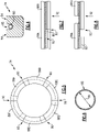
- the seal assembly 62 is formed of separate annular sections 88A-F.
- Each section 88A-F includes a radially outer sealing surface (or “radially-facing sealing surface") 84 ( Figure 4 ) that is separated by the annular slot 82.
- the sections 88A-F are mated at overlapping joints indicated at 90.
- the seal assembly 62 includes six annular sections 88A-F each separated and mated to an adjacent section at one of the joints 90. It should be appreciated that although six annular sections 88A-F are shown by way of example, more or less sections could be utilized and are within the scope and contemplation of this disclosure.
- the joints 90 are disposed to enable and accommodate circumferential expansion during engine operation. As the outer shaft 50 rotates, the annular sections 88A-F will be driven radially outward into sealing contact with the sealing surface 68 of the rotor 64. It should be appreciated that the seal 74 is in contact with the sealing surface 68 of the rotor 64 in an at rest condition and that rotation results in an increased force between sealing surfaces with only small amount of actual movement.
- the joints 90 extend radially and provide an overlap in an axial direction such that there is no open leak path in an axial direction.
- the annular sections 88A-F are secured within the groove 72 by the retainer 80.
- the retainer 80 holds the annular sections 88A-F together within the groove during initial assembly and periods where the engine is not operating.
- the example retainer 80 is a garter spring that provides a biasing force on the annular sections 88A-F radially inward.
- the retainer 80 could also be an elastomer material compatible with the temperature of the environment in which the seal 62 is provided.
- other materials and structures other than disclosed garter spring may be utilized for the retainer and are within the scope and contemplation of this disclosure.
- the retainer 80 includes an expandable inner diameter 86 that is determined to enable assembly and also seating within the annular slot 82 of the seal 74.
- the retainer 80 includes a diameter in cross-section that enables the retainer 80 to seat completely within the annular slot 82 such that that the retainer does not contact the sealing surface 68 of the rotor 64 during operation.
- the retainer 80 provides a biasing force sufficient to maintain the annular sections 88A-F together when not rotating while not restricting radial outward movement in response to rotation of the shaft 50.
- one of the joints 90 is shown from a point looking radially outward at an inner surface that is transverse to the axis of rotation. Airflow 92 is prevented from moving past the seal 74 due to the radial sealing contact with the radial inner sealing surface 68. The airflow 92 is prevented from moving axially past the seal 74 due to the overlapped joint 90. In the collapsed condition shown in Figure 7 , the retainer 80 holds ends of the annular sections 88A and 88B together.
- annular sections 88A and 88B will spread apart in response to radial expansion.
- the radial spreading between annular sections 88A and 88B spreads ends of the annular sections 88A and 88B apart.
- the overlapping joint 90 maintains sealing contact to prevent leakage past the seal in the axial direction. It should be appreciated that the spreading of annular sections 88A and 88b are exaggerated to illustrate the disclosed features and may be much smaller in operation.
- the segmented structure of the example seal 74 aids in initial assembly.
- the annular sections 88A-D are placed within the annular groove 72.
- the retainer 80 is placed in the annular slot 82 and secured to itself to exert a biasing force that limits radial expansion during operation and holds the annular sections 88A-D in place until the radially facing sealing surface of the rotor 64 is placed over the seal 74.
- Assembly of the seal 74 includes assembly of each of the annular sections 88A-D in an overlapping shiplap joint to enable radial expansion during rotation. The radial expansion accommodates thermal expansion of the rotor 64 and shaft 50.
- the overlapped portions of each annular section 88A-D prevent axial leakage through the seal 74.
- the seal 74 is formed from a carbon material. In other possible embodiments, the seal 74 may be formed from other materials including metals and non-metals that do not wear into either the shaft 50 or the rotor 64. In further disclosed embodiments, the seal 74 may be formed from ceramic, ceramic matrix composites or other polymer materials and composites that are compatible with the temperatures within the section of the compressor 52.
- the example seal assembly 62 contains airflow while reducing and/or preventing wear on the shaft 50 and rotor 64.
Description
- The present invention is related to a rotating seal assembly for sealing between co-rotating parts of a gas turbine engine, to a corresponding gas turbine engine assembly and to a method of assembling a rotating seal for a gas turbine engine.
- A gas turbine engine typically includes a fan section, a compressor section, a combustor section and a turbine section. Air entering the compressor section is compressed and delivered into the combustion section where it is mixed with fuel and ignited to generate a high-speed exhaust gas flow. The high-speed exhaust gas flow expands through the turbine section to drive the compressor and the fan section. The compressor section typically includes low and high pressure compressors, and the turbine section includes low and high pressure turbines.
- Seals are provided throughout the engine to control airflows. Some seals are disposed between relative rotating parts and are designed to accommodate wear. Other seals are disposed between parts that may rotate, but not relative to each other. Even without relative rotation, wear may occur due to vibrational, or other relative movement that occurs during engine operation.
- Turbine engine manufacturers continually seek improvements to engine performance including improvements to thermal and propulsive efficiencies.
-
EP 2,453,150 A1 discloses a seal assembly. -
US 2015/050130 A1 discloses a sealing device between two axisymmetric coaxial parts. -
EP 2,562,364 A1 discloses a rotating turbomachine seal. -
EP 2,803,825 A1 discloses a seal structure for a rotary machine, and a gas turbine engine with the same. -
EP 3,611,348 A1 discloses a gas turbine engine seal ring assembly. -
US 2019/323370 A1 discloses a segmented piston seal system. - In accordance with a first aspect of the present invention, there is provided a rotating seal assembly for sealing between co-rotating parts of a gas turbine engine as claimed in claim 1.
- In an embodiment of the foregoing rotating seal assembly for sealing between co-rotating parts of a gas turbine engine, the radially-outer-facing sealing surface comprises a sealing surface on axial sides of the slot.
- In a further embodiment of any of the foregoing rotating seal assemblies for sealing between co-rotating parts of a gas turbine engine, there is an overlapping interface between ends of the at least two annular sections.
- In a further embodiment of any of the foregoing rotating seal assemblies for sealing between co-rotating parts of a gas turbine engine, the at least two annular sections includes multiple annular sections each including an overlapping interface between adjacent ends.
- In a further embodiment of any of the foregoing rotating seal assemblies for sealing between co-rotating parts of a gas turbine engine, each of the at least two annular sections comprises a carbon material.
- The present invention also extends to a gas turbine engine assembly as claimed in claim 6.
- In an embodiment of the foregoing gas turbine engine assembly, the shaft includes a section of increased diameter with the annular groove positioned within the increased diameter.
- In a further embodiment of any of the foregoing gas turbine engine assemblies, the radial inner surface includes an axially extending portion.
- In a further embodiment of any of the foregoing gas turbine engines, the seal prevents hot airflow from moving forward past the seal.
- In accordance with a second aspect of the present disclosure, there is provided a method of assembling a rotating seal for a gas turbine engine as claimed in claim 10.
- In a further embodiment of any of the foregoing methods of assembling a rotating seal for a gas turbine engine, adjacent ends of each of the at least two annular sections overlap to maintain a complete annular seal with the seal in a radially expanded position.
- Although the different examples have the specific components shown in the illustrations, embodiments of this invention are not limited to those particular combinations. It is possible to use some of the components or features from one of the examples in combination with features or components from another one of the examples.
- These and other features disclosed herein can be best understood from the following specification and drawings, the following of which is a brief description.
-
-
Figure 1 is a schematic view of an example gas turbine engine. -
Figure 2 is a schematic view of a portion of an example compressor section including an example seal assembly embodiment. -
Figure 3 is a cross-section of an example seal assembly embodiment. -
Figure 4 is a cross-section of an example seal embodiment. -
Figure 5 is a front axial view of the example seal embodiment. -
Figure 6 is a schematic view of an example retainer embodiment. -
Figure 7 is a radial view of an outer radial surface of the example seal in a collapsed position. -
Figure 8 is a radial view of the outer radial surface of the example seal in a radially expanded position. -
Figure 1 schematically illustrates agas turbine engine 20. Thegas turbine engine 20 is disclosed herein as a two-spool turbofan that generally incorporates afan section 22, acompressor section 24, acombustor section 26 and aturbine section 28. Thefan section 22 drives air along a bypass flow path B in a bypass duct defined within anacelle 18, and also drives air along a core flow path C for compression and communication into thecombustor section 26 then expansion through theturbine section 28. Although depicted as a two-spool turbofan gas turbine engine in the disclosed non-limiting embodiment, it should be understood that the concepts described herein are not limited to use with two-spool turbofans as the teachings may be applied to other types of turbine engines including three-spool architectures. - The
exemplary engine 20 generally includes alow speed spool 30 and a high speed spool 32 mounted for rotation about an engine central longitudinal axis A relative to an enginestatic structure 36 viaseveral bearing systems 38. It should be understood that thevarious bearing systems 38 may alternatively or additionally be provided at different locations, and the location ofbearing systems 38 may be varied as appropriate to the application. - The
low speed spool 30 generally includes aninner shaft 40 that interconnects, a first (or low)pressure compressor 44 and a first (or low)pressure turbine 46. Theinner shaft 40 is connected to afan 42 through a speed change mechanism, which in exemplarygas turbine engine 20 is illustrated as a gearedarchitecture 48 to drive thefan 42 at a lower speed than thelow speed spool 30. The high speed spool 32 includes anouter shaft 50 that interconnects a second (or high)pressure compressor 52 and a second (or high)pressure turbine 54. Acombustor 56 is arranged inexemplary gas turbine 20 between thehigh pressure compressor 52 and thehigh pressure turbine 54. Amid-turbine frame 58 of the enginestatic structure 36 may be arranged generally between thehigh pressure turbine 54 and thelow pressure turbine 46. Themid-turbine frame 58 further supports bearingsystems 38 in theturbine section 28. Theinner shaft 40 and theouter shaft 50 are concentric and rotate viabearing systems 38 about the engine central longitudinal axis A which is collinear with their longitudinal axes. - The core airflow is compressed by the
low pressure compressor 44 then thehigh pressure compressor 52, mixed and burned with fuel in thecombustor 56, then expanded over thehigh pressure turbine 54 andlow pressure turbine 46. Themid-turbine frame 58 includes airfoils 60 which are in the core airflow path C. Theturbines low speed spool 30 and high speed spool 32 in response to the expansion. It will be appreciated that each of the positions of thefan section 22,compressor section 24,combustor section 26,turbine section 28, and fandrive gear system 48 may be varied. For example,gear system 48 may be located aft of the low pressure compressor, or aft of thecombustor section 26 or even aft ofturbine section 28, andfan 42 may be positioned forward or aft of the location ofgear system 48. - A
seal assembly 62 is provided to contain airflow produced in aft compartments of theengine 20. Theseal assembly 62 prevents hot airflow from accessing cooler parts of theengine 20. In one disclosed example embodiment, theseal assembly 62 is disposed within thehigh pressure compressor 52. In this example thehigh pressure compressor 52 is an eight stage compressor withforward stages 65 forward of theseal assembly 62 andaft stages 67 aft of theseal assembly 62. As appreciated, although the example seal is disclosed within an eight-stagehigh pressure compressor 52, other compressor configurations would benefit from this disclosure and are within the contemplated scope of this disclosure. Moreover, theexample seal assembly 62 may be utilized in other locations of theengine 20 for containing and controlling airflow. - Additionally, although the
example seal assembly 62 is disclosed by way of example with regard to use in a gas turbine engine, the example seal assembly may be used between any two co-rotating parts such as maybe contained in pumps, electric machines, compressors, steam turbines and other rotating structures. Accordingly, application of theseal assembly 62 in applications other than the disclosed gas turbine engine is within the contemplation and scope of this disclosure. - Referring to
Figure 2 with continued reference toFigure 1 , theexample seal assembly 62 is disposed between theouter shaft 50 and arotor 64. In the disclosed example, therotors 64 are part of thehigh pressure compressor 52 and are driven by theouter shaft 50. Theouter shaft 50 is concentric with the inner shaft and supported by bearing systems as shown inFigure 1 . Accordingly, therotors 64 rotate at the same speed as theouter shaft 50. Theseal assembly 62 prevents the flow of thehot air 92 from entering undesired stages of the high-pressure compressor 52. In this example, theseal assembly 62 prevents the flow from entering forward stages 65 of the high-pressure compressor 52 that are axially forward theseal assembly 62. The forward stages 65 are exposed to lower levels of thermal energy than aft stages 67. As can be appreciated, some portions of stage including theseal assembly 62 are heated because of the location of theseal assembly 62. Accordingly, the airflow schematically shown at 92 is contained aft of theseal assembly 62. - Referring to
Figure 3 with continued reference toFigure 2 , theseal assembly 62 includes aseal 74 disposed within anannular groove 72 defined in theshaft 50. Theshaft 50 includes afirst diameter 76 and asecond diameter 78. Thesecond diameter 78 is larger than thefirst diameter 76 and includes theannular groove 72. The outer radial surface of theshaft 50 tapers outward radially from thefirst diameter 76 to thesecond diameter 78 on both a forward and aft sides of theannular groove 72. - The
seal assembly 62 is annular and extends about the entire circumference of theshaft 50. Theexample seal 74 is approximately square in cross-section except for theannular slot 82. Aretainer 80 is provide within theannular slot 82 to hold theseal 74 within thegroove 72. The corners may be chamfered to reduce high stress concentration areas. Moreover, although theseal 74 is substantially square, other rectilinear shapes could be utilized and are within the contemplation and scope of this disclosure. Theseal 74 includes anannular slot 82 that is continuous about the circumference of theseal 74. Theseal 74 extends radially outward of thegroove 72 into sealing contact with theinner sealing surface 68 of therotor 64. - The
example rotor 64 includes the radiallyinner sealing surface 68 that extends into anaxially extending portion 66 that protrudes axially aft of a lower portion of therotor 64. Although the sealingsurface 68 is not connected to theshaft 50, theradially sealing surface 68, theportion 66 andouter shaft 50 rotate together. No relative rotation between therotor 64, sealingsurface 68, theportion 66 and outer shaft occurs. Theseal assembly 62 rotates with theshaft 50 against the sealingsurface 68 such that there is no relative rotation of theseal assembly 62. - Referring to
Figures 4 and 5 with continued reference toFigure 3 , theseal assembly 62 is formed of separateannular sections 88A-F. Eachsection 88A-F includes a radially outer sealing surface (or "radially-facing sealing surface") 84 (Figure 4 ) that is separated by theannular slot 82. Thesections 88A-F are mated at overlapping joints indicated at 90. In this example embodiment, theseal assembly 62 includes sixannular sections 88A-F each separated and mated to an adjacent section at one of thejoints 90. It should be appreciated that although sixannular sections 88A-F are shown by way of example, more or less sections could be utilized and are within the scope and contemplation of this disclosure. Thejoints 90 are disposed to enable and accommodate circumferential expansion during engine operation. As theouter shaft 50 rotates, theannular sections 88A-F will be driven radially outward into sealing contact with the sealingsurface 68 of therotor 64. It should be appreciated that theseal 74 is in contact with the sealingsurface 68 of therotor 64 in an at rest condition and that rotation results in an increased force between sealing surfaces with only small amount of actual movement. Thejoints 90 extend radially and provide an overlap in an axial direction such that there is no open leak path in an axial direction. - The
annular sections 88A-F are secured within thegroove 72 by theretainer 80. Theretainer 80 holds theannular sections 88A-F together within the groove during initial assembly and periods where the engine is not operating. - Referring to
Figure 6 within continued reference toFigures 3-5 , theexample retainer 80 is a garter spring that provides a biasing force on theannular sections 88A-F radially inward. Theretainer 80 could also be an elastomer material compatible with the temperature of the environment in which theseal 62 is provided. Moreover, other materials and structures other than disclosed garter spring may be utilized for the retainer and are within the scope and contemplation of this disclosure. Theretainer 80 includes an expandableinner diameter 86 that is determined to enable assembly and also seating within theannular slot 82 of theseal 74. Moreover, theretainer 80 includes a diameter in cross-section that enables theretainer 80 to seat completely within theannular slot 82 such that that the retainer does not contact the sealingsurface 68 of therotor 64 during operation. Theretainer 80 provides a biasing force sufficient to maintain theannular sections 88A-F together when not rotating while not restricting radial outward movement in response to rotation of theshaft 50. - Referring to
Figure 7 with continued reference toFigures 3-6 , one of thejoints 90 is shown from a point looking radially outward at an inner surface that is transverse to the axis of rotation.Airflow 92 is prevented from moving past theseal 74 due to the radial sealing contact with the radialinner sealing surface 68. Theairflow 92 is prevented from moving axially past theseal 74 due to the overlapped joint 90. In the collapsed condition shown inFigure 7 , theretainer 80 holds ends of theannular sections - Referring to
Figure 8 , as theshaft 50 rotates, theannular sections annular sections annular sections joint 90 maintains sealing contact to prevent leakage past the seal in the axial direction. It should be appreciated that the spreading ofannular sections 88A and 88b are exaggerated to illustrate the disclosed features and may be much smaller in operation. - The segmented structure of the
example seal 74 aids in initial assembly. During initial assembly, theannular sections 88A-D are placed within theannular groove 72. Theretainer 80 is placed in theannular slot 82 and secured to itself to exert a biasing force that limits radial expansion during operation and holds theannular sections 88A-D in place until the radially facing sealing surface of therotor 64 is placed over theseal 74. Assembly of theseal 74 includes assembly of each of theannular sections 88A-D in an overlapping shiplap joint to enable radial expansion during rotation. The radial expansion accommodates thermal expansion of therotor 64 andshaft 50. The overlapped portions of eachannular section 88A-D prevent axial leakage through theseal 74. - In one disclosed example embodiment, the
seal 74 is formed from a carbon material. In other possible embodiments, theseal 74 may be formed from other materials including metals and non-metals that do not wear into either theshaft 50 or therotor 64. In further disclosed embodiments, theseal 74 may be formed from ceramic, ceramic matrix composites or other polymer materials and composites that are compatible with the temperatures within the section of thecompressor 52. - Accordingly, the
example seal assembly 62 contains airflow while reducing and/or preventing wear on theshaft 50 androtor 64. - Although an example embodiment has been disclosed, a worker of ordinary skill in this art would recognize that certain modifications would come within the scope of this disclosure. For that reason, the following claims should be studied to determine the scope and content of this invention.
Claims (11)
- A rotating seal assembly (62) for sealing between co-rotating parts of a gas turbine engine (20) characterized in that it comprises:at least two annular sections (88A-F) forming a complete circumference, wherein each of the at least two annular sections (88A-F) is a separate part and includes a radially-outer-facing sealing surface (84) and an annular slot (82) disposed on a radially outer side of each of the at least two annular sections (88A-F); anda spring (80) disposed within the annular slot (82), wherein the spring (80) exerts a biasing force radially inward on the at least two annular sections (88A-F) to limit radial expansion of the at least two annular sections (88A-F).
- The rotating seal assembly as recited in claim 1, wherein the radially-outer-facing sealing surface (84) comprises a sealing surface on axial sides of the annular slot (82).
- The rotating seal assembly as recited in claim 1 or 2, including an overlapping interface between ends of the at least two annular sections (88A-F).
- The rotating seal assembly as recited in any preceding claim, wherein the at least two annular sections (88A-F) includes multiple annular sections (88A-F) each including an overlapping interface between adjacent ends.
- The rotating seal assembly as recited in any preceding claim, wherein each of the at least two annular sections (88A-F) comprises a carbon material.
- A gas turbine engine assembly comprising:a compressor (52) including a plurality of rotors (64), wherein at least one of the plurality of rotors (64) includes a radial inner sealing surface (68);a rotating shaft (50) driving rotation of the plurality of rotors (64), wherein the rotating shaft (50) includes an annular groove (72) proximate the radial inner sealing surface (68); andthe rotating seal assembly (62) as recited in any preceding claim disposed within the annular groove (72), wherein the radially-facing sealing surface (84) is engaged to the radial inner sealing surface (68).
- The gas turbine engine assembly as recited in claim 6, wherein the shaft (50) includes a section of increased diameter with the annular groove (72) positioned within the increased diameter.
- The gas turbine engine as recited in claim 6 or 7, wherein the radial inner sealing surface (68) includes an axially extending portion (66).
- The gas turbine engine as recited in any of claims 6 to 8, wherein the seal assembly (62) prevents hot airflow (92) from moving forward past the seal assembly (62).
- A method of assembling a rotating seal (74) for a gas turbine engine (20) characterized by:positioning at least two annular seal sections (88A-F) within an annular groove (72) formed in a shaft (50), wherein the at least two annular seal sections form a complete circumference and each include a radially-facing sealing surface (84);holding the at least two annular seal sections (88A-F) within the annular groove (72) with a spring (80) disposed within an annular slot (82) disposed on an outer radial side of each of the at least two annular seal sections (88A-F), wherein the spring (80) exerts a biasing force radially inward on the at least two annular sections (88A-F); andassembling a radially inner sealing surface (68) of a rotor (64) radially outward of the annular groove (72) and in sealing contact with the at least two annular sections (88A-F), wherein the shaft (50) and the rotor (64) rotate together such that there is no relative rotation therebetween and the seal (74) expands radially outward against the radially inner sealing surface (68) of the rotor (64) in response to rotation.
- The method as recited in claim 10, including overlapping adjacent ends of each of the at least two annular sections (88A-F) to maintain a complete annular seal with the seal (74) in a radially expanded position.
Applications Claiming Priority (1)
| Application Number | Priority Date | Filing Date | Title |
|---|---|---|---|
| US16/373,876 US11028713B2 (en) | 2019-04-03 | 2019-04-03 | Rotating carbon piston ring seal |
Publications (2)
| Publication Number | Publication Date |
|---|---|
| EP3719265A1 EP3719265A1 (en) | 2020-10-07 |
| EP3719265B1 true EP3719265B1 (en) | 2022-06-01 |
Family
ID=70189742
Family Applications (1)
| Application Number | Title | Priority Date | Filing Date |
|---|---|---|---|
| EP20168032.9A Active EP3719265B1 (en) | 2019-04-03 | 2020-04-03 | Rotating carbon piston ring seal |
Country Status (2)
| Country | Link |
|---|---|
| US (1) | US11028713B2 (en) |
| EP (1) | EP3719265B1 (en) |
Families Citing this family (2)
| Publication number | Priority date | Publication date | Assignee | Title |
|---|---|---|---|---|
| US11542819B2 (en) * | 2021-02-17 | 2023-01-03 | Pratt & Whitney Canada Corp. | Split ring seal for gas turbine engine rotor |
| US11821320B2 (en) | 2021-06-04 | 2023-11-21 | General Electric Company | Turbine engine with a rotor seal assembly |
Family Cites Families (12)
| Publication number | Priority date | Publication date | Assignee | Title |
|---|---|---|---|---|
| US4082296A (en) * | 1976-05-26 | 1978-04-04 | Stein Philip C | Seal for sealing between a rotating member and a housing |
| US4971306A (en) * | 1987-12-25 | 1990-11-20 | Eagle Industry Co., Ltd. | Seals for cylindrical surfaces |
| US7066470B2 (en) | 2001-12-05 | 2006-06-27 | General Electric Company | Active seal assembly |
| GB0226685D0 (en) | 2002-11-15 | 2002-12-24 | Rolls Royce Plc | Sealing arrangement |
| US20120112415A1 (en) | 2010-11-10 | 2012-05-10 | United Technologies Corporation | Rotating seal ring with targeted split surface orientation |
| US8939710B2 (en) | 2011-08-24 | 2015-01-27 | United Technologies Corporation | Rotating turbomachine seal |
| JP5705753B2 (en) | 2012-01-12 | 2015-04-22 | 三菱重工業株式会社 | Seal structure of rotating machine and gas turbine provided with the same |
| FR2985764B1 (en) | 2012-01-16 | 2014-02-28 | Snecma | COAXIAL INTER-TREE SEALING DEVICE OF A TURBOMACHINE |
| WO2015081037A1 (en) * | 2013-11-26 | 2015-06-04 | General Electric Company | Radial tie-bolt support spring |
| US9638326B2 (en) * | 2014-12-15 | 2017-05-02 | Kaydon Ring & Seal, Inc. | Arch-bound ring seal and ring seal system including an arch-bound ring seal |
| US10989058B2 (en) | 2018-04-19 | 2021-04-27 | General Electric Company | Segmented piston seal system |
| US10920617B2 (en) | 2018-08-17 | 2021-02-16 | Raytheon Technologies Corporation | Gas turbine engine seal ring assembly |
-
2019
- 2019-04-03 US US16/373,876 patent/US11028713B2/en active Active
-
2020
- 2020-04-03 EP EP20168032.9A patent/EP3719265B1/en active Active
Also Published As
| Publication number | Publication date |
|---|---|
| EP3719265A1 (en) | 2020-10-07 |
| US20200318489A1 (en) | 2020-10-08 |
| US11028713B2 (en) | 2021-06-08 |
Similar Documents
| Publication | Publication Date | Title |
|---|---|---|
| US20140255156A1 (en) | Non-contacting seals for geared gas turbine engine bearing compartments | |
| US10208674B2 (en) | Multi-axial brush seal | |
| EP3000967A2 (en) | Gas turbine engine blade slot heat shield | |
| US20130195603A1 (en) | Turbomachine fan clutch | |
| EP3453838B1 (en) | Contacting dry face seal with tapered carbon nose | |
| EP3653915B1 (en) | Seal disassembly aid | |
| US11624325B2 (en) | Face seal arrangement for reduced force and pressure | |
| EP3719265B1 (en) | Rotating carbon piston ring seal | |
| EP3453839B1 (en) | Gas turbine engine blade outer air seal | |
| WO2015089431A1 (en) | Blade outer air seal with secondary air sealing | |
| EP3428408A1 (en) | Gas turbine engine variable vane end wall insert | |
| EP3960992A2 (en) | Seal runner flow damper | |
| EP3690193B1 (en) | Seal and method for assembling a seal arrangement | |
| EP3617458B1 (en) | Annular seal for a gas turbine engine | |
| EP4012162B1 (en) | Rotating sleeve controlling clearance of seal assembly of gas turbine engine | |
| EP3722568B1 (en) | Bearing compartment seal configuration for a gas turbine engine | |
| EP3719359B1 (en) | Extended pilot ring seal arrangement for installation damage prevention | |
| EP3744957B1 (en) | Thermal management of a shaft | |
| EP3372793B1 (en) | Non-contacting seals for geared gas turbine engine bearing compartments | |
| EP3851642B1 (en) | Combustor to vane sealing assembly and method of forming same | |
| US11466591B2 (en) | Reduced radial clearance seal system | |
| EP3865668B1 (en) | Combustor to vane sealing assembly and method of forming same | |
| EP3708773A2 (en) | Seal for a rotor stack, corresponding gas turbine engine and method of sealing a shaft relatively to a rotor disk |
Legal Events
| Date | Code | Title | Description |
|---|---|---|---|
| PUAI | Public reference made under article 153(3) epc to a published international application that has entered the european phase |
Free format text: ORIGINAL CODE: 0009012 |
|
| STAA | Information on the status of an ep patent application or granted ep patent |
Free format text: STATUS: THE APPLICATION HAS BEEN PUBLISHED |
|
| AK | Designated contracting states |
Kind code of ref document: A1 Designated state(s): AL AT BE BG CH CY CZ DE DK EE ES FI FR GB GR HR HU IE IS IT LI LT LU LV MC MK MT NL NO PL PT RO RS SE SI SK SM TR |
|
| AX | Request for extension of the european patent |
Extension state: BA ME |
|
| STAA | Information on the status of an ep patent application or granted ep patent |
Free format text: STATUS: REQUEST FOR EXAMINATION WAS MADE |
|
| 17P | Request for examination filed |
Effective date: 20210407 |
|
| RBV | Designated contracting states (corrected) |
Designated state(s): AL AT BE BG CH CY CZ DE DK EE ES FI FR GB GR HR HU IE IS IT LI LT LU LV MC MK MT NL NO PL PT RO RS SE SI SK SM TR |
|
| RIC1 | Information provided on ipc code assigned before grant |
Ipc: F16J 15/3232 20160101ALI20210916BHEP Ipc: F16J 15/3208 20160101ALI20210916BHEP Ipc: F16J 15/02 20060101ALI20210916BHEP Ipc: F01D 11/00 20060101AFI20210916BHEP |
|
| GRAP | Despatch of communication of intention to grant a patent |
Free format text: ORIGINAL CODE: EPIDOSNIGR1 |
|
| STAA | Information on the status of an ep patent application or granted ep patent |
Free format text: STATUS: GRANT OF PATENT IS INTENDED |
|
| INTG | Intention to grant announced |
Effective date: 20211123 |
|
| GRAS | Grant fee paid |
Free format text: ORIGINAL CODE: EPIDOSNIGR3 |
|
| GRAA | (expected) grant |
Free format text: ORIGINAL CODE: 0009210 |
|
| STAA | Information on the status of an ep patent application or granted ep patent |
Free format text: STATUS: THE PATENT HAS BEEN GRANTED |
|
| AK | Designated contracting states |
Kind code of ref document: B1 Designated state(s): AL AT BE BG CH CY CZ DE DK EE ES FI FR GB GR HR HU IE IS IT LI LT LU LV MC MK MT NL NO PL PT RO RS SE SI SK SM TR |
|
| REG | Reference to a national code |
Ref country code: GB Ref legal event code: FG4D |
|
| REG | Reference to a national code |
Ref country code: AT Ref legal event code: REF Ref document number: 1495492 Country of ref document: AT Kind code of ref document: T Effective date: 20220615 Ref country code: CH Ref legal event code: EP |
|
| REG | Reference to a national code |
Ref country code: IE Ref legal event code: FG4D |
|
| REG | Reference to a national code |
Ref country code: DE Ref legal event code: R096 Ref document number: 602020003320 Country of ref document: DE |
|
| REG | Reference to a national code |
Ref country code: LT Ref legal event code: MG9D |
|
| REG | Reference to a national code |
Ref country code: NL Ref legal event code: MP Effective date: 20220601 |
|
| PG25 | Lapsed in a contracting state [announced via postgrant information from national office to epo] |
Ref country code: SE Free format text: LAPSE BECAUSE OF FAILURE TO SUBMIT A TRANSLATION OF THE DESCRIPTION OR TO PAY THE FEE WITHIN THE PRESCRIBED TIME-LIMIT Effective date: 20220601 Ref country code: NO Free format text: LAPSE BECAUSE OF FAILURE TO SUBMIT A TRANSLATION OF THE DESCRIPTION OR TO PAY THE FEE WITHIN THE PRESCRIBED TIME-LIMIT Effective date: 20220901 Ref country code: LT Free format text: LAPSE BECAUSE OF FAILURE TO SUBMIT A TRANSLATION OF THE DESCRIPTION OR TO PAY THE FEE WITHIN THE PRESCRIBED TIME-LIMIT Effective date: 20220601 Ref country code: HR Free format text: LAPSE BECAUSE OF FAILURE TO SUBMIT A TRANSLATION OF THE DESCRIPTION OR TO PAY THE FEE WITHIN THE PRESCRIBED TIME-LIMIT Effective date: 20220601 Ref country code: GR Free format text: LAPSE BECAUSE OF FAILURE TO SUBMIT A TRANSLATION OF THE DESCRIPTION OR TO PAY THE FEE WITHIN THE PRESCRIBED TIME-LIMIT Effective date: 20220902 Ref country code: FI Free format text: LAPSE BECAUSE OF FAILURE TO SUBMIT A TRANSLATION OF THE DESCRIPTION OR TO PAY THE FEE WITHIN THE PRESCRIBED TIME-LIMIT Effective date: 20220601 Ref country code: ES Free format text: LAPSE BECAUSE OF FAILURE TO SUBMIT A TRANSLATION OF THE DESCRIPTION OR TO PAY THE FEE WITHIN THE PRESCRIBED TIME-LIMIT Effective date: 20220601 Ref country code: BG Free format text: LAPSE BECAUSE OF FAILURE TO SUBMIT A TRANSLATION OF THE DESCRIPTION OR TO PAY THE FEE WITHIN THE PRESCRIBED TIME-LIMIT Effective date: 20220901 |
|
| REG | Reference to a national code |
Ref country code: AT Ref legal event code: MK05 Ref document number: 1495492 Country of ref document: AT Kind code of ref document: T Effective date: 20220601 |
|
| PG25 | Lapsed in a contracting state [announced via postgrant information from national office to epo] |
Ref country code: RS Free format text: LAPSE BECAUSE OF FAILURE TO SUBMIT A TRANSLATION OF THE DESCRIPTION OR TO PAY THE FEE WITHIN THE PRESCRIBED TIME-LIMIT Effective date: 20220601 Ref country code: PL Free format text: LAPSE BECAUSE OF FAILURE TO SUBMIT A TRANSLATION OF THE DESCRIPTION OR TO PAY THE FEE WITHIN THE PRESCRIBED TIME-LIMIT Effective date: 20220601 Ref country code: LV Free format text: LAPSE BECAUSE OF FAILURE TO SUBMIT A TRANSLATION OF THE DESCRIPTION OR TO PAY THE FEE WITHIN THE PRESCRIBED TIME-LIMIT Effective date: 20220601 |
|
| PG25 | Lapsed in a contracting state [announced via postgrant information from national office to epo] |
Ref country code: NL Free format text: LAPSE BECAUSE OF FAILURE TO SUBMIT A TRANSLATION OF THE DESCRIPTION OR TO PAY THE FEE WITHIN THE PRESCRIBED TIME-LIMIT Effective date: 20220601 |
|
| PG25 | Lapsed in a contracting state [announced via postgrant information from national office to epo] |
Ref country code: SM Free format text: LAPSE BECAUSE OF FAILURE TO SUBMIT A TRANSLATION OF THE DESCRIPTION OR TO PAY THE FEE WITHIN THE PRESCRIBED TIME-LIMIT Effective date: 20220601 Ref country code: SK Free format text: LAPSE BECAUSE OF FAILURE TO SUBMIT A TRANSLATION OF THE DESCRIPTION OR TO PAY THE FEE WITHIN THE PRESCRIBED TIME-LIMIT Effective date: 20220601 Ref country code: RO Free format text: LAPSE BECAUSE OF FAILURE TO SUBMIT A TRANSLATION OF THE DESCRIPTION OR TO PAY THE FEE WITHIN THE PRESCRIBED TIME-LIMIT Effective date: 20220601 Ref country code: PT Free format text: LAPSE BECAUSE OF FAILURE TO SUBMIT A TRANSLATION OF THE DESCRIPTION OR TO PAY THE FEE WITHIN THE PRESCRIBED TIME-LIMIT Effective date: 20221003 Ref country code: EE Free format text: LAPSE BECAUSE OF FAILURE TO SUBMIT A TRANSLATION OF THE DESCRIPTION OR TO PAY THE FEE WITHIN THE PRESCRIBED TIME-LIMIT Effective date: 20220601 Ref country code: CZ Free format text: LAPSE BECAUSE OF FAILURE TO SUBMIT A TRANSLATION OF THE DESCRIPTION OR TO PAY THE FEE WITHIN THE PRESCRIBED TIME-LIMIT Effective date: 20220601 Ref country code: AT Free format text: LAPSE BECAUSE OF FAILURE TO SUBMIT A TRANSLATION OF THE DESCRIPTION OR TO PAY THE FEE WITHIN THE PRESCRIBED TIME-LIMIT Effective date: 20220601 |
|
| PG25 | Lapsed in a contracting state [announced via postgrant information from national office to epo] |
Ref country code: IS Free format text: LAPSE BECAUSE OF FAILURE TO SUBMIT A TRANSLATION OF THE DESCRIPTION OR TO PAY THE FEE WITHIN THE PRESCRIBED TIME-LIMIT Effective date: 20221001 |
|
| REG | Reference to a national code |
Ref country code: DE Ref legal event code: R097 Ref document number: 602020003320 Country of ref document: DE |
|
| PG25 | Lapsed in a contracting state [announced via postgrant information from national office to epo] |
Ref country code: AL Free format text: LAPSE BECAUSE OF FAILURE TO SUBMIT A TRANSLATION OF THE DESCRIPTION OR TO PAY THE FEE WITHIN THE PRESCRIBED TIME-LIMIT Effective date: 20220601 |
|
| PLBE | No opposition filed within time limit |
Free format text: ORIGINAL CODE: 0009261 |
|
| STAA | Information on the status of an ep patent application or granted ep patent |
Free format text: STATUS: NO OPPOSITION FILED WITHIN TIME LIMIT |
|
| PG25 | Lapsed in a contracting state [announced via postgrant information from national office to epo] |
Ref country code: DK Free format text: LAPSE BECAUSE OF FAILURE TO SUBMIT A TRANSLATION OF THE DESCRIPTION OR TO PAY THE FEE WITHIN THE PRESCRIBED TIME-LIMIT Effective date: 20220601 |
|
| PGFP | Annual fee paid to national office [announced via postgrant information from national office to epo] |
Ref country code: FR Payment date: 20230321 Year of fee payment: 4 |
|
| 26N | No opposition filed |
Effective date: 20230302 |
|
| PG25 | Lapsed in a contracting state [announced via postgrant information from national office to epo] |
Ref country code: SI Free format text: LAPSE BECAUSE OF FAILURE TO SUBMIT A TRANSLATION OF THE DESCRIPTION OR TO PAY THE FEE WITHIN THE PRESCRIBED TIME-LIMIT Effective date: 20220601 |
|
| P01 | Opt-out of the competence of the unified patent court (upc) registered |
Effective date: 20230521 |
|
| PGFP | Annual fee paid to national office [announced via postgrant information from national office to epo] |
Ref country code: DE Payment date: 20230321 Year of fee payment: 4 |
|
| REG | Reference to a national code |
Ref country code: CH Ref legal event code: PL |
|
| PG25 | Lapsed in a contracting state [announced via postgrant information from national office to epo] |
Ref country code: LU Free format text: LAPSE BECAUSE OF NON-PAYMENT OF DUE FEES Effective date: 20230403 |
|
| REG | Reference to a national code |
Ref country code: BE Ref legal event code: MM Effective date: 20230430 |
|
| PG25 | Lapsed in a contracting state [announced via postgrant information from national office to epo] |
Ref country code: MC Free format text: LAPSE BECAUSE OF FAILURE TO SUBMIT A TRANSLATION OF THE DESCRIPTION OR TO PAY THE FEE WITHIN THE PRESCRIBED TIME-LIMIT Effective date: 20220601 |
|
| PG25 | Lapsed in a contracting state [announced via postgrant information from national office to epo] |
Ref country code: MC Free format text: LAPSE BECAUSE OF FAILURE TO SUBMIT A TRANSLATION OF THE DESCRIPTION OR TO PAY THE FEE WITHIN THE PRESCRIBED TIME-LIMIT Effective date: 20220601 Ref country code: LI Free format text: LAPSE BECAUSE OF NON-PAYMENT OF DUE FEES Effective date: 20230430 Ref country code: IT Free format text: LAPSE BECAUSE OF FAILURE TO SUBMIT A TRANSLATION OF THE DESCRIPTION OR TO PAY THE FEE WITHIN THE PRESCRIBED TIME-LIMIT Effective date: 20220601 Ref country code: CH Free format text: LAPSE BECAUSE OF NON-PAYMENT OF DUE FEES Effective date: 20230430 |
|
| REG | Reference to a national code |
Ref country code: IE Ref legal event code: MM4A |
|
| PG25 | Lapsed in a contracting state [announced via postgrant information from national office to epo] |
Ref country code: BE Free format text: LAPSE BECAUSE OF NON-PAYMENT OF DUE FEES Effective date: 20230430 |
|
| PG25 | Lapsed in a contracting state [announced via postgrant information from national office to epo] |
Ref country code: IE Free format text: LAPSE BECAUSE OF NON-PAYMENT OF DUE FEES Effective date: 20230403 |