EP3719258A1 - Aube mobile d'une turbomachine - Google Patents
Aube mobile d'une turbomachine Download PDFInfo
- Publication number
- EP3719258A1 EP3719258A1 EP20161689.3A EP20161689A EP3719258A1 EP 3719258 A1 EP3719258 A1 EP 3719258A1 EP 20161689 A EP20161689 A EP 20161689A EP 3719258 A1 EP3719258 A1 EP 3719258A1
- Authority
- EP
- European Patent Office
- Prior art keywords
- channel section
- inlet
- radially
- blade
- inlet channel
- Prior art date
- Legal status (The legal status is an assumption and is not a legal conclusion. Google has not performed a legal analysis and makes no representation as to the accuracy of the status listed.)
- Granted
Links
- 238000001816 cooling Methods 0.000 claims abstract description 68
- 239000000463 material Substances 0.000 claims abstract description 20
- 238000000034 method Methods 0.000 claims abstract description 20
- 239000002826 coolant Substances 0.000 claims abstract description 8
- 238000011144 upstream manufacturing Methods 0.000 claims description 17
- 230000007423 decrease Effects 0.000 claims description 3
- 230000004323 axial length Effects 0.000 claims description 2
- 238000011161 development Methods 0.000 description 4
- 230000018109 developmental process Effects 0.000 description 4
- 230000000712 assembly Effects 0.000 description 3
- 238000000429 assembly Methods 0.000 description 3
- 239000012530 fluid Substances 0.000 description 1
Images


Classifications
-
- F—MECHANICAL ENGINEERING; LIGHTING; HEATING; WEAPONS; BLASTING
- F01—MACHINES OR ENGINES IN GENERAL; ENGINE PLANTS IN GENERAL; STEAM ENGINES
- F01D—NON-POSITIVE DISPLACEMENT MACHINES OR ENGINES, e.g. STEAM TURBINES
- F01D5/00—Blades; Blade-carrying members; Heating, heat-insulating, cooling or antivibration means on the blades or the members
- F01D5/12—Blades
- F01D5/14—Form or construction
- F01D5/18—Hollow blades, i.e. blades with cooling or heating channels or cavities; Heating, heat-insulating or cooling means on blades
-
- F—MECHANICAL ENGINEERING; LIGHTING; HEATING; WEAPONS; BLASTING
- F01—MACHINES OR ENGINES IN GENERAL; ENGINE PLANTS IN GENERAL; STEAM ENGINES
- F01D—NON-POSITIVE DISPLACEMENT MACHINES OR ENGINES, e.g. STEAM TURBINES
- F01D25/00—Component parts, details, or accessories, not provided for in, or of interest apart from, other groups
- F01D25/08—Cooling; Heating; Heat-insulation
- F01D25/12—Cooling
-
- F—MECHANICAL ENGINEERING; LIGHTING; HEATING; WEAPONS; BLASTING
- F01—MACHINES OR ENGINES IN GENERAL; ENGINE PLANTS IN GENERAL; STEAM ENGINES
- F01D—NON-POSITIVE DISPLACEMENT MACHINES OR ENGINES, e.g. STEAM TURBINES
- F01D5/00—Blades; Blade-carrying members; Heating, heat-insulating, cooling or antivibration means on the blades or the members
- F01D5/02—Blade-carrying members, e.g. rotors
- F01D5/04—Blade-carrying members, e.g. rotors for radial-flow machines or engines
- F01D5/043—Blade-carrying members, e.g. rotors for radial-flow machines or engines of the axial inlet- radial outlet, or vice versa, type
- F01D5/046—Heating, heat insulation or cooling means
-
- F—MECHANICAL ENGINEERING; LIGHTING; HEATING; WEAPONS; BLASTING
- F01—MACHINES OR ENGINES IN GENERAL; ENGINE PLANTS IN GENERAL; STEAM ENGINES
- F01D—NON-POSITIVE DISPLACEMENT MACHINES OR ENGINES, e.g. STEAM TURBINES
- F01D5/00—Blades; Blade-carrying members; Heating, heat-insulating, cooling or antivibration means on the blades or the members
- F01D5/02—Blade-carrying members, e.g. rotors
- F01D5/08—Heating, heat-insulating or cooling means
- F01D5/081—Cooling fluid being directed on the side of the rotor disc or at the roots of the blades
-
- F—MECHANICAL ENGINEERING; LIGHTING; HEATING; WEAPONS; BLASTING
- F01—MACHINES OR ENGINES IN GENERAL; ENGINE PLANTS IN GENERAL; STEAM ENGINES
- F01D—NON-POSITIVE DISPLACEMENT MACHINES OR ENGINES, e.g. STEAM TURBINES
- F01D5/00—Blades; Blade-carrying members; Heating, heat-insulating, cooling or antivibration means on the blades or the members
- F01D5/12—Blades
- F01D5/14—Form or construction
- F01D5/18—Hollow blades, i.e. blades with cooling or heating channels or cavities; Heating, heat-insulating or cooling means on blades
- F01D5/187—Convection cooling
-
- F—MECHANICAL ENGINEERING; LIGHTING; HEATING; WEAPONS; BLASTING
- F01—MACHINES OR ENGINES IN GENERAL; ENGINE PLANTS IN GENERAL; STEAM ENGINES
- F01D—NON-POSITIVE DISPLACEMENT MACHINES OR ENGINES, e.g. STEAM TURBINES
- F01D5/00—Blades; Blade-carrying members; Heating, heat-insulating, cooling or antivibration means on the blades or the members
- F01D5/30—Fixing blades to rotors; Blade roots ; Blade spacers
- F01D5/3007—Fixing blades to rotors; Blade roots ; Blade spacers of axial insertion type
-
- F—MECHANICAL ENGINEERING; LIGHTING; HEATING; WEAPONS; BLASTING
- F05—INDEXING SCHEMES RELATING TO ENGINES OR PUMPS IN VARIOUS SUBCLASSES OF CLASSES F01-F04
- F05D—INDEXING SCHEME FOR ASPECTS RELATING TO NON-POSITIVE-DISPLACEMENT MACHINES OR ENGINES, GAS-TURBINES OR JET-PROPULSION PLANTS
- F05D2260/00—Function
- F05D2260/20—Heat transfer, e.g. cooling
- F05D2260/221—Improvement of heat transfer
-
- F—MECHANICAL ENGINEERING; LIGHTING; HEATING; WEAPONS; BLASTING
- F05—INDEXING SCHEMES RELATING TO ENGINES OR PUMPS IN VARIOUS SUBCLASSES OF CLASSES F01-F04
- F05D—INDEXING SCHEME FOR ASPECTS RELATING TO NON-POSITIVE-DISPLACEMENT MACHINES OR ENGINES, GAS-TURBINES OR JET-PROPULSION PLANTS
- F05D2260/00—Function
- F05D2260/94—Functionality given by mechanical stress related aspects such as low cycle fatigue [LCF] of high cycle fatigue [HCF]
- F05D2260/941—Functionality given by mechanical stress related aspects such as low cycle fatigue [LCF] of high cycle fatigue [HCF] particularly aimed at mechanical or thermal stress reduction
Definitions
- the invention relates to a rotor blade of a turbomachine.
- Fluid flow machines such as turbines or compressors, have stator-side assemblies and rotor-side assemblies.
- the rotor-side assemblies of a turbo machine include what is known as the turbo machine rotor, which has a hub body and rotor blades that extend radially outward from the hub body.
- a rotor blade of a turbomachine has a flow-guiding blade as well as a blade root via which the rotor blade can be fastened in the hub body of the turbomachine.
- the blade of the turbomachine has a flow inlet edge, a flow outlet edge and flow guide surfaces for a process medium that extend between the flow inlet edge and the flow outlet edge and are also referred to as suction side and pressure side.
- the blade root via which the rotor blade can be fastened in the hub body of the turbomachine, is typically configured like a fir tree with at least two projections spaced apart from one another as seen in the radial direction of the rotor blade.
- a moving blade also has a so-called inner shroud, which is arranged between the airfoil and the blade root, as seen in the radial direction of the moving blade.
- An outer shroud can optionally adjoin the airfoil radially on the outside.
- a cooling channel is integrated. The cooling channel extends over both the blade root and the blade.
- An inlet of the cooling channel is formed radially on the inside at the blade root.
- An exit of the cooling channel can be formed radially on the outside on the blade or on the radially outer outer shroud or at another point.
- the present invention is based on the object of creating a novel rotor blade of a turbomachine which, despite the cooling channel, has high strength.
- the inlet of the cooling channel is formed from a first inlet channel section and a second inlet channel section, which is arranged behind the first inlet channel section when viewed in the axial direction of the blade root and between which a material web extends.
- the first inlet channel section of the cooling channel and the second inlet channel section of the cooling channel merge into a merging channel section of the cooling channel which, viewed in the radial direction, is arranged radially outside or radially above the uppermost or radially outermost projection of the blade root and radially inside or radially below the inner shroud. This is used for effective cooling of the rotor blade while at the same time providing the rotor blade with high strength.
- the first inlet channel section and the second inlet channel section preferably run from radially inside to radially outside in a straight line in the radial direction. In that region of the blade root in which the first inlet channel section and the second inlet channel section run in a straight line in the radial direction, an axial thickness of the material web is constant. This is used to effectively cool the rotor blade while at the same time providing the rotor blade with high strength.
- the first inlet channel section and the second inlet channel section then each run bent or curved in the direction of the merging channel section, specifically in the direction of an upstream or axially front end of the blade root with respect to the process medium flow.
- an axial thickness of the material web preferably decreases in the direction of the union channel section. This also serves to effectively cool the rotor blade while at the same time providing the rotor blade with high strength.
- the first inlet channel section is curved in the direction of the upstream or axially front end of the blade root with a first radius of curvature.
- the second inlet channel section is curved with a second radius of curvature in the direction of the upstream or axially front end of the blade root.
- the first radius of curvature is at least as large, preferably larger, than the second radius of curvature.
- the cooling channel initially extends radially outwards in the direction of a radially outer deflecting channel section after the union channel section. Subsequent to the radially outer deflection channel section, the cooling channel extends radially inward in the direction of a radially inner deflection channel section. Following the radially inner deflection channel section, the cooling channel extends radially outward in the direction of a cooling channel outlet.
- the radially inner deflection channel section is arranged in the radial direction above or radially outside the uppermost or radially outermost projection of the blade root and below or radially inside the inner shroud. This also serves to effectively cool the rotor blade while maintaining its high strength.
- the first inlet channel section and the second inlet channel section have the same flow cross-sections. This ensures effective cooling of the rotor blade.
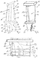
- Figs. 1 and 2 show views of a rotor blade 10, wherein the rotor blade 10 comprises a flow-guiding blade 11 and a blade root 12.
- the flow-guiding blade 11 serves to guide the flow of a process medium, in particular process gas, which flows through the turbomachine, the blade 11 having a flow inlet edge 13 for the process medium, a flow outlet edge 14 for the process medium and flow guide surfaces 15 extending between the flow inlet edge 13 and the flow outlet edge 14 , 16 for the process medium.
- the flow guide surfaces 15, 16 form a suction side and a pressure side.
- the blade root 12 is used to fasten the rotor blade 10 in a hub body, not shown, of the turbomachine.
- the blade root 12 is configured like a fir tree with at least two projections 17 spaced apart from one another as seen in the radial direction of the rotor blade 10. In the exemplary embodiment shown, three such projections 17 are spaced apart from one another in the radial direction of the rotor blade 10.
- the fir tree profile of the blade root 12 tapers between adjacent projections 17.
- One projection 17 and the tapering section of the fir tree profile arranged directly above the respective projection 17 each define a so-called tooth of the fir tree profile.
- the rotor blade 10 also has an inner shroud 18 which, viewed in the radial direction of the rotor blade 10, is arranged between the blade blade 11 and the blade root 12 of the rotor blade 10.
- the inner shroud 18 delimits a flow guide channel for the process medium radially on the inside.
- the rotor blade 10 also has an outer shroud 19.
- the outer shroud 19 delimits the flow guide channel for the process medium radially on the outside.
- contours of the cooling channel 20 are shown in dashed lines.
- contours of the cooling channel 20 are shown in sections in dashed lines.
- Fig. 4, 5 , 6 and 7 show only the contours of the cooling channel 20 without the actual rotor blade 10.
- the cooling channel 20 has an inlet or cooling channel inlet 21 which is formed radially on the inside on the blade root 12.
- the cooling channel 20 also has an outlet or cooling channel outlet 31, which is formed in particular radially on the outside on the blade 11 or on the outer shroud 19.
- the cooling channel outlet 31 can also be psotionized at another point.
- Fig. 3 , 5 , 6 and 7 show details of the inlet or cooling channel inlet 21 of the cooling channel 20.
- the inlet or cooling channel inlet 21 of the cooling channel 20 comprises a first inlet channel section 22 and a second inlet channel section 23.
- the first inlet channel section 22 viewed in the axial direction, is positioned at the front in relation to the flow of the process medium, i.e. closer to an end of the blade root 12 which is upstream or axially forward in relation to the process medium flow than the second inlet channel section 23.
- the second inlet channel section 23 is arranged behind the first inlet channel section 22 as seen in the axial direction of the blade root 12.
- the blade root 12 is not used to guide the process medium but only to fasten or assemble the rotor blade 10 on the hub body. Nevertheless, the blade root 12 has two opposite axial ends, namely an upstream or axially front end in relation to the process medium flow and an end which is downstream or axially rear in relation to the process medium flow.
- the first inlet channel section 22 is arranged between the upstream or axially front end of the blade root 12 and the second inlet channel section 23.
- the second inlet channel section 23 is arranged between the first inlet channel section 22 and the downstream or axially rear end of the blade root 12.
- a material web 24 extends between the two inlet channel sections 22 and 23, which are spaced apart from one another in the axial direction of the blade root 12. This material web 24 stiffens the rotor blade 10 in the area of its blade root 12.
- This connecting channel section 25 is arranged or formed above or radially outside of the uppermost or radially outermost projection 17 and below or radially inside of the inner shroud 18, as seen in the radial direction of the rotor blade 10.
- the material web 24 extends from radially inside to radially outside into a section of the blade root 12 which is arranged above or radially outside of the radially outermost and thus uppermost projection 17 of the blade root 12, whereby the strength of the rotor blade 10 in the Area of the blade root 12 can be adjusted particularly advantageously.
- the material web 24 preferably extends into the region of the narrowest cross section of the radially outermost and thus uppermost tooth of the fir tree profile of the blade root 12.
- the first inlet channel section 22 defines a first flow inlet opening radially on the inside at the blade root 12 and the second inlet channel section 23 defines a second flow inlet opening radially on the inside at the blade root 12.
- These, like the inlet channel sections 22, 23 themselves, are positioned one behind the other as seen in the axial direction of the blade root 12 and are spaced apart from one another via the material web 24.
- the first flow inlet opening and thus the first inlet channel section 22 has a defined axial distance .DELTA.x from the upstream or axially front end of the blade root 12 in relation to the process medium flow.
- the defined axial distance ⁇ x between the first inlet channel section 22 and thus the first flow inlet opening and the upstream or axially front end of the blade root 12 is preferably between 10% and 30%, in particular between 15% and 25%, of the axial length L of the blade root 12.
- the material web 24 has a constant thickness in the axial direction.
- the axial distance ⁇ x defined above between the first inlet channel section 22 and the upstream end of the blade root 12 relates to the area of the first inlet channel section 22 that extends in a straight line radially outward in the radial direction.
- the two inlet channel sections 22, 23 in the radial direction run in a straight line
- the two inlet channel sections 22, 23 run bent or curved in the direction of the connecting channel section 25.
- the distance ⁇ x defined above changes in the area of this curvature.
- the curvature of the inlet channel sections 22, 23 between the rectilinear areas thereof and the connecting channel section 25 is directed in the direction of the upstream or axially front end of the blade root 12 or in the direction of the flow inlet edge 13 of the rotor blade 11.
- the axial thickness of the material web 24 preferably decreases in the direction of the union channel section 25.
- the material web 24 tapers in this area.
- the axial thickness of the material web 24 can also be constant in this area.
- the cooling channel 20 extends in the illustrated embodiment with a further section 26 first radially outwards in the direction of a radially outer deflection channel section 27, then after the radially outer deflection channel section 27 with a further section 28 radially inwards in the direction of a inner deflecting channel section 29 and then to this radially inner deflecting channel section 29 with a further section 30 radially outward in the direction of the cooling channel outlet 31.
- the sections 26, 28 and 30 of the cooling channel 20 extend inside the blade 11. There are also other courses of the Cooling channel 20 downstream of the connecting channel section 25 possible.
- the radially inner deflection channel section 29 is arranged above or radially outside of the uppermost or radially outermost projection 17 of the blade root 12 and below or radially inside of the inner shroud 18, seen in the radial direction, in the axial direction opposite the inlet channel sections 22, 23 axially rearward in the direction of the downstream or axially rear end of the blade root 12 offset.
- the upper or radially outer deflection channel section 27 can extend into the region of the outer shroud 19.
- cooling medium accordingly flows into the cooling channel 20 via the flow inlet openings of the inlet channel sections 22, 23, this coolant flowing through the two inlet channel sections 22, 23 being combined in the area of the merging channel section 25. This takes place in the area of the blade root 12. Subsequently, the cooling medium is guided via the channel sections 26, 27, 28, 29 and 30 in the direction of the cooling channel outlet 31.
- the duct sections 26, 28 and 30 extending in the radial direction extend over the radial extent of the blade 11. Between the duct sections 26, 28 and between the duct sections 28 and 30, a flow deflection takes place via the deflecting duct sections 27 and 29.
- Figures 6 and 7 show geometric parameters of the flow channel 20 in the area of the cooling channel inlet 21. So can Fig. 6 it can be seen that the first inlet channel section 22 is curved with a first radius of curvature R1 and the second inlet channel section 23 is curved with a second radius of curvature R2 in the direction of the upstream axial end of the blade root 12.
- the first radius of curvature R1 is at least as large as the second radius of curvature R2, R1 is preferably greater than R2.
- Fig. 7 visualize the flow cross-sections of the inlet channel sections 22 and 23. Fig. 7 it can be seen that the two inlet channel sections 22 and 23 have the same flow cross-sections A, specifically over their entire radial extent up to the union channel section 25.
- cooling medium can enter the cooling duct 20 in the radial direction in the region of the inlet duct sections 22, 23, whereby an effective entry of the cooling medium into the cooling duct 20 is possible.
- the inlet channel sections 22, 23, which are spaced apart from one another in the axial direction are at a defined axial distance from the upstream end of the blade root 12.
- the inlet channel sections 22, 23 are spaced apart from one another in the axial direction by the material web 24. This serves to provide a high strength of the rotor blade 10 in the area of the blade root 12.
- the web 24 extends in the radial direction above or radially outward of the uppermost or radially outermost projection 17 of the fir tree-like blade root 12. This ensures optimal strength in the area of the blade root 12.
- the radially inner deflecting duct section 29 is also arranged axially spaced from the merging duct section 25.
- This radially inner deflection channel section 29 extends into the blade root 12, but ends at a distance from the radially outermost projection 17 of the fir tree-like blade root 12 radially outside or radially above the web 24.
- the rotor blade 10 according to the invention allows optimal cooling with high strength. It is used in particular in gas turbines.
Landscapes
- Engineering & Computer Science (AREA)
- Mechanical Engineering (AREA)
- General Engineering & Computer Science (AREA)
- Turbine Rotor Nozzle Sealing (AREA)
- Structures Of Non-Positive Displacement Pumps (AREA)
Priority Applications (1)
| Application Number | Priority Date | Filing Date | Title |
|---|---|---|---|
| RS20230575A RS64375B1 (sr) | 2019-04-04 | 2020-03-09 | Pokretna lopatica strujne mašine |
Applications Claiming Priority (1)
| Application Number | Priority Date | Filing Date | Title |
|---|---|---|---|
| DE102019108811.9A DE102019108811B4 (de) | 2019-04-04 | 2019-04-04 | Laufschaufel einer Strömungsmaschine |
Publications (2)
| Publication Number | Publication Date |
|---|---|
| EP3719258A1 true EP3719258A1 (fr) | 2020-10-07 |
| EP3719258B1 EP3719258B1 (fr) | 2023-05-03 |
Family
ID=69784091
Family Applications (1)
| Application Number | Title | Priority Date | Filing Date |
|---|---|---|---|
| EP20161689.3A Active EP3719258B1 (fr) | 2019-04-04 | 2020-03-09 | Aube mobile d'une turbomachine |
Country Status (9)
| Country | Link |
|---|---|
| US (1) | US11408289B2 (fr) |
| EP (1) | EP3719258B1 (fr) |
| JP (1) | JP7424893B2 (fr) |
| KR (1) | KR20200117866A (fr) |
| CN (1) | CN111794805A (fr) |
| DE (1) | DE102019108811B4 (fr) |
| ES (1) | ES2950136T3 (fr) |
| IL (1) | IL272567B2 (fr) |
| RS (1) | RS64375B1 (fr) |
Families Citing this family (1)
| Publication number | Priority date | Publication date | Assignee | Title |
|---|---|---|---|---|
| DE102019125779B4 (de) * | 2019-09-25 | 2024-03-21 | Man Energy Solutions Se | Schaufel einer Strömungsmaschine |
Citations (6)
| Publication number | Priority date | Publication date | Assignee | Title |
|---|---|---|---|---|
| US20120163995A1 (en) * | 2010-12-27 | 2012-06-28 | Wardle Brian Kenneth | Turbine blade |
| US20120171046A1 (en) * | 2010-12-30 | 2012-07-05 | General Electric Company | Apparatus and methods for cooling platform regions of turbine rotor blades |
| EP2489838A2 (fr) * | 2011-02-17 | 2012-08-22 | Rolls-Royce plc | Composant refroidi pour turbine d'un moteur de turbine à gaz |
| EP2700787A1 (fr) * | 2011-04-22 | 2014-02-26 | Mitsubishi Heavy Industries, Ltd. | Aube et machine rotative |
| US20140096538A1 (en) * | 2012-10-05 | 2014-04-10 | General Electric Company | Platform cooling of a turbine blade assembly |
| US20140321961A1 (en) * | 2012-05-31 | 2014-10-30 | United Technologies Corporation | Mate face cooling holes for gas turbine engine component |
Family Cites Families (13)
| Publication number | Priority date | Publication date | Assignee | Title |
|---|---|---|---|---|
| US6966756B2 (en) * | 2004-01-09 | 2005-11-22 | General Electric Company | Turbine bucket cooling passages and internal core for producing the passages |
| US7467922B2 (en) * | 2005-07-25 | 2008-12-23 | Siemens Aktiengesellschaft | Cooled turbine blade or vane for a gas turbine, and use of a turbine blade or vane of this type |
| EP1895096A1 (fr) * | 2006-09-04 | 2008-03-05 | Siemens Aktiengesellschaft | Aube mobile de turbine refroidie |
| US20120269649A1 (en) * | 2011-04-22 | 2012-10-25 | Christopher Rawlings | Turbine blade with improved trailing edge cooling |
| EP2535515A1 (fr) * | 2011-06-16 | 2012-12-19 | Siemens Aktiengesellschaft | Section d'ancrage de pale de rotor dotée d'un passage de refroidissement et procédé pour la fourniture de liquide de refroidissement à une pale de rotor |
| US20140093386A1 (en) * | 2012-09-28 | 2014-04-03 | Solar Turbines Incorporated | Cooled turbine blade with inner spar |
| US20150308449A1 (en) | 2014-03-11 | 2015-10-29 | United Technologies Corporation | Gas turbine engine component with brazed cover |
| FR3020402B1 (fr) * | 2014-04-24 | 2019-06-14 | Safran Aircraft Engines | Aube pour turbine de turbomachine comprenant un circuit de refroidissement a homogeneite amelioree |
| US10174622B2 (en) * | 2016-04-12 | 2019-01-08 | Solar Turbines Incorporated | Wrapped serpentine passages for turbine blade cooling |
| EP3232001A1 (fr) | 2016-04-15 | 2017-10-18 | Siemens Aktiengesellschaft | Aube rotorique de turbine |
| EP3241990A1 (fr) * | 2016-05-04 | 2017-11-08 | Siemens Aktiengesellschaft | Pale ou aube de turbomachine comportant un élément de génération de vortex |
| EP3421721A1 (fr) * | 2017-06-28 | 2019-01-02 | Siemens Aktiengesellschaft | Composant de turbomachine et procédé de fabrication d'un composant de turbomachine |
| US11008873B2 (en) * | 2019-02-05 | 2021-05-18 | Raytheon Technologies Corporation | Turbine blade tip wall cooling |
-
2019
- 2019-04-04 DE DE102019108811.9A patent/DE102019108811B4/de active Active
-
2020
- 2020-02-09 IL IL272567A patent/IL272567B2/en unknown
- 2020-03-09 RS RS20230575A patent/RS64375B1/sr unknown
- 2020-03-09 EP EP20161689.3A patent/EP3719258B1/fr active Active
- 2020-03-09 ES ES20161689T patent/ES2950136T3/es active Active
- 2020-03-17 US US16/821,322 patent/US11408289B2/en active Active
- 2020-03-25 KR KR1020200035977A patent/KR20200117866A/ko not_active Application Discontinuation
- 2020-04-03 CN CN202010259131.7A patent/CN111794805A/zh active Pending
- 2020-04-03 JP JP2020067546A patent/JP7424893B2/ja active Active
Patent Citations (6)
| Publication number | Priority date | Publication date | Assignee | Title |
|---|---|---|---|---|
| US20120163995A1 (en) * | 2010-12-27 | 2012-06-28 | Wardle Brian Kenneth | Turbine blade |
| US20120171046A1 (en) * | 2010-12-30 | 2012-07-05 | General Electric Company | Apparatus and methods for cooling platform regions of turbine rotor blades |
| EP2489838A2 (fr) * | 2011-02-17 | 2012-08-22 | Rolls-Royce plc | Composant refroidi pour turbine d'un moteur de turbine à gaz |
| EP2700787A1 (fr) * | 2011-04-22 | 2014-02-26 | Mitsubishi Heavy Industries, Ltd. | Aube et machine rotative |
| US20140321961A1 (en) * | 2012-05-31 | 2014-10-30 | United Technologies Corporation | Mate face cooling holes for gas turbine engine component |
| US20140096538A1 (en) * | 2012-10-05 | 2014-04-10 | General Electric Company | Platform cooling of a turbine blade assembly |
Also Published As
| Publication number | Publication date |
|---|---|
| IL272567B2 (en) | 2023-10-01 |
| US11408289B2 (en) | 2022-08-09 |
| CN111794805A (zh) | 2020-10-20 |
| ES2950136T3 (es) | 2023-10-05 |
| US20200318485A1 (en) | 2020-10-08 |
| DE102019108811B4 (de) | 2024-02-29 |
| IL272567B1 (en) | 2023-06-01 |
| RS64375B1 (sr) | 2023-08-31 |
| KR20200117866A (ko) | 2020-10-14 |
| EP3719258B1 (fr) | 2023-05-03 |
| JP2020169644A (ja) | 2020-10-15 |
| JP7424893B2 (ja) | 2024-01-30 |
| DE102019108811A1 (de) | 2020-10-08 |
| IL272567A (en) | 2020-10-29 |
Similar Documents
| Publication | Publication Date | Title |
|---|---|---|
| EP2473743B1 (fr) | Aube mobile de compresseur pour un compresseur axial | |
| EP2478186B1 (fr) | Rotor de turbomachine | |
| EP3176370B1 (fr) | Ensemble d'aubes directrices pour turbomachine | |
| EP0799973B1 (fr) | Contour de paroi pour une turbomachine axiale | |
| EP1898054B1 (fr) | Turbine a gaz | |
| DE102005025213A1 (de) | Schaufel einer Axialströmungsmaschine | |
| WO2005106207A1 (fr) | Aube de compresseur et compresseur | |
| EP1766192A1 (fr) | Roue a aubes d'une turbine presentant une aube et au moins un canal refrigerant | |
| EP2140111B1 (fr) | Turbomachine | |
| DE102014115475A1 (de) | Hinterkantenausrundung einer Gasturbinenleitschaufel | |
| CH701927B1 (de) | Statoranordnung, Kompressor und Gasturbinenmotor. | |
| DE60019965T2 (de) | Axialturbine für gase | |
| EP2410131B1 (fr) | Rotor d'une turbomachine | |
| EP3401504A1 (fr) | Grille d'aube | |
| EP3719258B1 (fr) | Aube mobile d'une turbomachine | |
| DE102018206601A1 (de) | Schaufel, Schaufelsegment und Baugruppe für eine Turbomaschine und Turbomaschine | |
| EP2696042B1 (fr) | Turbomachine avec au moins un stator | |
| EP3798416B1 (fr) | Aube d'une turbomachine | |
| EP3431707B1 (fr) | Aube, couronne d'aubes, segment de couronne d'aubes et turbomachine | |
| EP3483391B1 (fr) | Pale de turbine d'une couronne de pale de turbine | |
| EP3404211A1 (fr) | Segment de grille d'aubes d'une turbine avec paroi de plateforme contourée, grille d'aubes, canal d'aube, plateforme, turbine et moteur d'aéronef associés | |
| EP2650475B1 (fr) | Pale pour une turbomachine, agencement d'aubes ainsi que la turbomachine | |
| DE102008031781A1 (de) | Schaufelgitter für eine Strömungsmaschine und Strömungsmaschine mit einem solchen Schaufelgitter | |
| EP2927503A1 (fr) | Compresseur de turbine à gaz, moteur d'avion et méthode de dimensionnement | |
| EP3536974A1 (fr) | Compresseur de turbine à gaz |
Legal Events
| Date | Code | Title | Description |
|---|---|---|---|
| PUAI | Public reference made under article 153(3) epc to a published international application that has entered the european phase |
Free format text: ORIGINAL CODE: 0009012 |
|
| STAA | Information on the status of an ep patent application or granted ep patent |
Free format text: STATUS: THE APPLICATION HAS BEEN PUBLISHED |
|
| AK | Designated contracting states |
Kind code of ref document: A1 Designated state(s): AL AT BE BG CH CY CZ DE DK EE ES FI FR GB GR HR HU IE IS IT LI LT LU LV MC MK MT NL NO PL PT RO RS SE SI SK SM TR |
|
| AX | Request for extension of the european patent |
Extension state: BA ME |
|
| STAA | Information on the status of an ep patent application or granted ep patent |
Free format text: STATUS: REQUEST FOR EXAMINATION WAS MADE |
|
| 17P | Request for examination filed |
Effective date: 20210318 |
|
| RBV | Designated contracting states (corrected) |
Designated state(s): AL AT BE BG CH CY CZ DE DK EE ES FI FR GB GR HR HU IE IS IT LI LT LU LV MC MK MT NL NO PL PT RO RS SE SI SK SM TR |
|
| GRAP | Despatch of communication of intention to grant a patent |
Free format text: ORIGINAL CODE: EPIDOSNIGR1 |
|
| STAA | Information on the status of an ep patent application or granted ep patent |
Free format text: STATUS: GRANT OF PATENT IS INTENDED |
|
| RIC1 | Information provided on ipc code assigned before grant |
Ipc: F01D 5/30 20060101ALI20221219BHEP Ipc: F01D 5/18 20060101AFI20221219BHEP |
|
| INTG | Intention to grant announced |
Effective date: 20230110 |
|
| GRAS | Grant fee paid |
Free format text: ORIGINAL CODE: EPIDOSNIGR3 |
|
| GRAA | (expected) grant |
Free format text: ORIGINAL CODE: 0009210 |
|
| STAA | Information on the status of an ep patent application or granted ep patent |
Free format text: STATUS: THE PATENT HAS BEEN GRANTED |
|
| AK | Designated contracting states |
Kind code of ref document: B1 Designated state(s): AL AT BE BG CH CY CZ DE DK EE ES FI FR GB GR HR HU IE IS IT LI LT LU LV MC MK MT NL NO PL PT RO RS SE SI SK SM TR |
|
| REG | Reference to a national code |
Ref country code: GB Ref legal event code: FG4D Free format text: NOT ENGLISH |
|
| REG | Reference to a national code |
Ref country code: DE Ref legal event code: R096 Ref document number: 502020003132 Country of ref document: DE |
|
| REG | Reference to a national code |
Ref country code: AT Ref legal event code: REF Ref document number: 1564749 Country of ref document: AT Kind code of ref document: T Effective date: 20230515 Ref country code: CH Ref legal event code: EP |
|
| REG | Reference to a national code |
Ref country code: IE Ref legal event code: FG4D Free format text: LANGUAGE OF EP DOCUMENT: GERMAN |
|
| REG | Reference to a national code |
Ref country code: SE Ref legal event code: TRGR |
|
| REG | Reference to a national code |
Ref country code: LT Ref legal event code: MG9D |
|
| REG | Reference to a national code |
Ref country code: NL Ref legal event code: MP Effective date: 20230503 |
|
| REG | Reference to a national code |
Ref country code: ES Ref legal event code: FG2A Ref document number: 2950136 Country of ref document: ES Kind code of ref document: T3 Effective date: 20231005 |
|
| PG25 | Lapsed in a contracting state [announced via postgrant information from national office to epo] |
Ref country code: PT Free format text: LAPSE BECAUSE OF FAILURE TO SUBMIT A TRANSLATION OF THE DESCRIPTION OR TO PAY THE FEE WITHIN THE PRESCRIBED TIME-LIMIT Effective date: 20230904 Ref country code: NO Free format text: LAPSE BECAUSE OF FAILURE TO SUBMIT A TRANSLATION OF THE DESCRIPTION OR TO PAY THE FEE WITHIN THE PRESCRIBED TIME-LIMIT Effective date: 20230803 Ref country code: NL Free format text: LAPSE BECAUSE OF FAILURE TO SUBMIT A TRANSLATION OF THE DESCRIPTION OR TO PAY THE FEE WITHIN THE PRESCRIBED TIME-LIMIT Effective date: 20230503 |
|
| PG25 | Lapsed in a contracting state [announced via postgrant information from national office to epo] |
Ref country code: PL Free format text: LAPSE BECAUSE OF FAILURE TO SUBMIT A TRANSLATION OF THE DESCRIPTION OR TO PAY THE FEE WITHIN THE PRESCRIBED TIME-LIMIT Effective date: 20230503 Ref country code: LV Free format text: LAPSE BECAUSE OF FAILURE TO SUBMIT A TRANSLATION OF THE DESCRIPTION OR TO PAY THE FEE WITHIN THE PRESCRIBED TIME-LIMIT Effective date: 20230503 Ref country code: LT Free format text: LAPSE BECAUSE OF FAILURE TO SUBMIT A TRANSLATION OF THE DESCRIPTION OR TO PAY THE FEE WITHIN THE PRESCRIBED TIME-LIMIT Effective date: 20230503 Ref country code: IS Free format text: LAPSE BECAUSE OF FAILURE TO SUBMIT A TRANSLATION OF THE DESCRIPTION OR TO PAY THE FEE WITHIN THE PRESCRIBED TIME-LIMIT Effective date: 20230903 Ref country code: HR Free format text: LAPSE BECAUSE OF FAILURE TO SUBMIT A TRANSLATION OF THE DESCRIPTION OR TO PAY THE FEE WITHIN THE PRESCRIBED TIME-LIMIT Effective date: 20230503 Ref country code: GR Free format text: LAPSE BECAUSE OF FAILURE TO SUBMIT A TRANSLATION OF THE DESCRIPTION OR TO PAY THE FEE WITHIN THE PRESCRIBED TIME-LIMIT Effective date: 20230804 |
|
| PG25 | Lapsed in a contracting state [announced via postgrant information from national office to epo] |
Ref country code: FI Free format text: LAPSE BECAUSE OF FAILURE TO SUBMIT A TRANSLATION OF THE DESCRIPTION OR TO PAY THE FEE WITHIN THE PRESCRIBED TIME-LIMIT Effective date: 20230503 |
|
| PG25 | Lapsed in a contracting state [announced via postgrant information from national office to epo] |
Ref country code: SK Free format text: LAPSE BECAUSE OF FAILURE TO SUBMIT A TRANSLATION OF THE DESCRIPTION OR TO PAY THE FEE WITHIN THE PRESCRIBED TIME-LIMIT Effective date: 20230503 |
|
| PG25 | Lapsed in a contracting state [announced via postgrant information from national office to epo] |
Ref country code: SM Free format text: LAPSE BECAUSE OF FAILURE TO SUBMIT A TRANSLATION OF THE DESCRIPTION OR TO PAY THE FEE WITHIN THE PRESCRIBED TIME-LIMIT Effective date: 20230503 Ref country code: SK Free format text: LAPSE BECAUSE OF FAILURE TO SUBMIT A TRANSLATION OF THE DESCRIPTION OR TO PAY THE FEE WITHIN THE PRESCRIBED TIME-LIMIT Effective date: 20230503 Ref country code: RO Free format text: LAPSE BECAUSE OF FAILURE TO SUBMIT A TRANSLATION OF THE DESCRIPTION OR TO PAY THE FEE WITHIN THE PRESCRIBED TIME-LIMIT Effective date: 20230503 Ref country code: EE Free format text: LAPSE BECAUSE OF FAILURE TO SUBMIT A TRANSLATION OF THE DESCRIPTION OR TO PAY THE FEE WITHIN THE PRESCRIBED TIME-LIMIT Effective date: 20230503 Ref country code: DK Free format text: LAPSE BECAUSE OF FAILURE TO SUBMIT A TRANSLATION OF THE DESCRIPTION OR TO PAY THE FEE WITHIN THE PRESCRIBED TIME-LIMIT Effective date: 20230503 |
|
| REG | Reference to a national code |
Ref country code: DE Ref legal event code: R097 Ref document number: 502020003132 Country of ref document: DE |
|
| PLBE | No opposition filed within time limit |
Free format text: ORIGINAL CODE: 0009261 |
|
| STAA | Information on the status of an ep patent application or granted ep patent |
Free format text: STATUS: NO OPPOSITION FILED WITHIN TIME LIMIT |
|
| 26N | No opposition filed |
Effective date: 20240206 |
|
| PGFP | Annual fee paid to national office [announced via postgrant information from national office to epo] |
Ref country code: DE Payment date: 20240320 Year of fee payment: 5 Ref country code: CZ Payment date: 20240229 Year of fee payment: 5 Ref country code: GB Payment date: 20240321 Year of fee payment: 5 |
|
| PG25 | Lapsed in a contracting state [announced via postgrant information from national office to epo] |
Ref country code: SI Free format text: LAPSE BECAUSE OF FAILURE TO SUBMIT A TRANSLATION OF THE DESCRIPTION OR TO PAY THE FEE WITHIN THE PRESCRIBED TIME-LIMIT Effective date: 20230503 |