EP3719178B1 - Electrochemical anti-microbial treatment and inert gas generating system and method - Google Patents
Electrochemical anti-microbial treatment and inert gas generating system and method Download PDFInfo
- Publication number
- EP3719178B1 EP3719178B1 EP19209251.8A EP19209251A EP3719178B1 EP 3719178 B1 EP3719178 B1 EP 3719178B1 EP 19209251 A EP19209251 A EP 19209251A EP 3719178 B1 EP3719178 B1 EP 3719178B1
- Authority
- EP
- European Patent Office
- Prior art keywords
- ozone
- flow path
- gas
- water
- anode
- Prior art date
- Legal status (The legal status is an assumption and is not a legal conclusion. Google has not performed a legal analysis and makes no representation as to the accuracy of the status listed.)
- Active
Links
- 238000000034 method Methods 0.000 title claims description 31
- 239000011261 inert gas Substances 0.000 title claims description 8
- 230000000845 anti-microbial effect Effects 0.000 title description 3
- 239000004599 antimicrobial Substances 0.000 title description 2
- XLYOFNOQVPJJNP-UHFFFAOYSA-N water Substances O XLYOFNOQVPJJNP-UHFFFAOYSA-N 0.000 claims description 116
- CBENFWSGALASAD-UHFFFAOYSA-N Ozone Chemical compound [O-][O+]=O CBENFWSGALASAD-UHFFFAOYSA-N 0.000 claims description 97
- 239000012530 fluid Substances 0.000 claims description 71
- 239000000446 fuel Substances 0.000 claims description 52
- 238000003860 storage Methods 0.000 claims description 50
- 238000009826 distribution Methods 0.000 claims description 49
- 239000007789 gas Substances 0.000 claims description 45
- 239000007788 liquid Substances 0.000 claims description 35
- QVGXLLKOCUKJST-UHFFFAOYSA-N atomic oxygen Chemical compound [O] QVGXLLKOCUKJST-UHFFFAOYSA-N 0.000 claims description 34
- 239000001301 oxygen Substances 0.000 claims description 34
- 229910052760 oxygen Inorganic materials 0.000 claims description 34
- 239000002828 fuel tank Substances 0.000 claims description 32
- 239000000463 material Substances 0.000 claims description 26
- 239000001257 hydrogen Substances 0.000 claims description 13
- 229910052739 hydrogen Inorganic materials 0.000 claims description 13
- 238000004891 communication Methods 0.000 claims description 12
- UFHFLCQGNIYNRP-UHFFFAOYSA-N Hydrogen Chemical compound [H][H] UFHFLCQGNIYNRP-UHFFFAOYSA-N 0.000 claims description 11
- 230000004044 response Effects 0.000 claims description 10
- 239000000203 mixture Substances 0.000 claims description 9
- 230000008569 process Effects 0.000 claims description 9
- 238000012546 transfer Methods 0.000 claims description 7
- IJGRMHOSHXDMSA-UHFFFAOYSA-N Atomic nitrogen Chemical compound N#N IJGRMHOSHXDMSA-UHFFFAOYSA-N 0.000 description 22
- 239000012528 membrane Substances 0.000 description 15
- 229910052757 nitrogen Inorganic materials 0.000 description 11
- 239000003054 catalyst Substances 0.000 description 8
- 238000006243 chemical reaction Methods 0.000 description 7
- 230000000813 microbial effect Effects 0.000 description 7
- NBIIXXVUZAFLBC-UHFFFAOYSA-N Phosphoric acid Chemical compound OP(O)(O)=O NBIIXXVUZAFLBC-UHFFFAOYSA-N 0.000 description 6
- 230000003197 catalytic effect Effects 0.000 description 5
- 238000011109 contamination Methods 0.000 description 5
- 239000003792 electrolyte Substances 0.000 description 5
- 238000007254 oxidation reaction Methods 0.000 description 5
- 239000002245 particle Substances 0.000 description 5
- -1 rhuthenium Chemical compound 0.000 description 5
- KDLHZDBZIXYQEI-UHFFFAOYSA-N Palladium Chemical compound [Pd] KDLHZDBZIXYQEI-UHFFFAOYSA-N 0.000 description 4
- 230000003115 biocidal effect Effects 0.000 description 4
- 230000015572 biosynthetic process Effects 0.000 description 4
- 239000002360 explosive Substances 0.000 description 4
- 238000004519 manufacturing process Methods 0.000 description 4
- BASFCYQUMIYNBI-UHFFFAOYSA-N platinum Chemical compound [Pt] BASFCYQUMIYNBI-UHFFFAOYSA-N 0.000 description 4
- 239000011347 resin Substances 0.000 description 4
- 229920005989 resin Polymers 0.000 description 4
- QAOWNCQODCNURD-UHFFFAOYSA-N Sulfuric acid Chemical compound OS(O)(=O)=O QAOWNCQODCNURD-UHFFFAOYSA-N 0.000 description 3
- 229910000147 aluminium phosphate Inorganic materials 0.000 description 3
- 238000004140 cleaning Methods 0.000 description 3
- 238000002485 combustion reaction Methods 0.000 description 3
- 239000000356 contaminant Substances 0.000 description 3
- 238000005868 electrolysis reaction Methods 0.000 description 3
- 230000007613 environmental effect Effects 0.000 description 3
- 238000004880 explosion Methods 0.000 description 3
- 229920000554 ionomer Polymers 0.000 description 3
- 230000003647 oxidation Effects 0.000 description 3
- 229960004838 phosphoric acid Drugs 0.000 description 3
- 235000011007 phosphoric acid Nutrition 0.000 description 3
- 239000000758 substrate Substances 0.000 description 3
- 230000001629 suppression Effects 0.000 description 3
- 241000894006 Bacteria Species 0.000 description 2
- OKTJSMMVPCPJKN-UHFFFAOYSA-N Carbon Chemical compound [C] OKTJSMMVPCPJKN-UHFFFAOYSA-N 0.000 description 2
- 241000233866 Fungi Species 0.000 description 2
- PXHVJJICTQNCMI-UHFFFAOYSA-N Nickel Chemical compound [Ni] PXHVJJICTQNCMI-UHFFFAOYSA-N 0.000 description 2
- 239000011230 binding agent Substances 0.000 description 2
- 230000003750 conditioning effect Effects 0.000 description 2
- 239000002274 desiccant Substances 0.000 description 2
- 229910001882 dioxygen Inorganic materials 0.000 description 2
- 230000005611 electricity Effects 0.000 description 2
- 238000003487 electrochemical reaction Methods 0.000 description 2
- 239000003456 ion exchange resin Substances 0.000 description 2
- 229920003303 ion-exchange polymer Polymers 0.000 description 2
- 229910052741 iridium Inorganic materials 0.000 description 2
- GKOZUEZYRPOHIO-UHFFFAOYSA-N iridium atom Chemical compound [Ir] GKOZUEZYRPOHIO-UHFFFAOYSA-N 0.000 description 2
- 239000011244 liquid electrolyte Substances 0.000 description 2
- 238000012423 maintenance Methods 0.000 description 2
- 229910052751 metal Inorganic materials 0.000 description 2
- 239000002184 metal Substances 0.000 description 2
- 229910044991 metal oxide Inorganic materials 0.000 description 2
- 150000004706 metal oxides Chemical class 0.000 description 2
- 229910052762 osmium Inorganic materials 0.000 description 2
- SYQBFIAQOQZEGI-UHFFFAOYSA-N osmium atom Chemical compound [Os] SYQBFIAQOQZEGI-UHFFFAOYSA-N 0.000 description 2
- 230000001590 oxidative effect Effects 0.000 description 2
- 229910052763 palladium Inorganic materials 0.000 description 2
- 229910052697 platinum Inorganic materials 0.000 description 2
- 229920000642 polymer Polymers 0.000 description 2
- 238000006722 reduction reaction Methods 0.000 description 2
- 229910052703 rhodium Inorganic materials 0.000 description 2
- 239000010948 rhodium Substances 0.000 description 2
- MHOVAHRLVXNVSD-UHFFFAOYSA-N rhodium atom Chemical compound [Rh] MHOVAHRLVXNVSD-UHFFFAOYSA-N 0.000 description 2
- 239000002904 solvent Substances 0.000 description 2
- 239000002028 Biomass Substances 0.000 description 1
- MYMOFIZGZYHOMD-UHFFFAOYSA-N Dioxygen Chemical compound O=O MYMOFIZGZYHOMD-UHFFFAOYSA-N 0.000 description 1
- LFQSCWFLJHTTHZ-UHFFFAOYSA-N Ethanol Chemical compound CCO LFQSCWFLJHTTHZ-UHFFFAOYSA-N 0.000 description 1
- KJTLSVCANCCWHF-UHFFFAOYSA-N Ruthenium Chemical compound [Ru] KJTLSVCANCCWHF-UHFFFAOYSA-N 0.000 description 1
- RTAQQCXQSZGOHL-UHFFFAOYSA-N Titanium Chemical compound [Ti] RTAQQCXQSZGOHL-UHFFFAOYSA-N 0.000 description 1
- QCWXUUIWCKQGHC-UHFFFAOYSA-N Zirconium Chemical compound [Zr] QCWXUUIWCKQGHC-UHFFFAOYSA-N 0.000 description 1
- 239000002253 acid Substances 0.000 description 1
- 230000002378 acidificating effect Effects 0.000 description 1
- 150000007513 acids Chemical class 0.000 description 1
- 239000011149 active material Substances 0.000 description 1
- 229910045601 alloy Inorganic materials 0.000 description 1
- 239000000956 alloy Substances 0.000 description 1
- 238000000429 assembly Methods 0.000 description 1
- 230000000712 assembly Effects 0.000 description 1
- 230000008901 benefit Effects 0.000 description 1
- 239000006227 byproduct Substances 0.000 description 1
- 229910052799 carbon Inorganic materials 0.000 description 1
- 238000005660 chlorination reaction Methods 0.000 description 1
- 238000009833 condensation Methods 0.000 description 1
- 230000005494 condensation Effects 0.000 description 1
- 239000004020 conductor Substances 0.000 description 1
- 238000001816 cooling Methods 0.000 description 1
- 238000005260 corrosion Methods 0.000 description 1
- 230000007797 corrosion Effects 0.000 description 1
- 230000007423 decrease Effects 0.000 description 1
- 230000000779 depleting effect Effects 0.000 description 1
- 238000000151 deposition Methods 0.000 description 1
- 230000000249 desinfective effect Effects 0.000 description 1
- 238000001514 detection method Methods 0.000 description 1
- 229910003460 diamond Inorganic materials 0.000 description 1
- 239000010432 diamond Substances 0.000 description 1
- 238000007598 dipping method Methods 0.000 description 1
- 230000000694 effects Effects 0.000 description 1
- 238000006056 electrooxidation reaction Methods 0.000 description 1
- 229910021397 glassy carbon Inorganic materials 0.000 description 1
- PCHJSUWPFVWCPO-UHFFFAOYSA-N gold Chemical compound [Au] PCHJSUWPFVWCPO-UHFFFAOYSA-N 0.000 description 1
- 229910052737 gold Inorganic materials 0.000 description 1
- 239000010931 gold Substances 0.000 description 1
- 229910002804 graphite Inorganic materials 0.000 description 1
- 239000010439 graphite Substances 0.000 description 1
- 239000010797 grey water Substances 0.000 description 1
- 229910052736 halogen Inorganic materials 0.000 description 1
- 150000002367 halogens Chemical class 0.000 description 1
- 230000036541 health Effects 0.000 description 1
- 229930195733 hydrocarbon Natural products 0.000 description 1
- 150000002430 hydrocarbons Chemical class 0.000 description 1
- 125000002887 hydroxy group Chemical group [H]O* 0.000 description 1
- 238000011065 in-situ storage Methods 0.000 description 1
- 238000007641 inkjet printing Methods 0.000 description 1
- 238000009434 installation Methods 0.000 description 1
- 239000010416 ion conductor Substances 0.000 description 1
- 239000003014 ion exchange membrane Substances 0.000 description 1
- 229920000831 ionic polymer Polymers 0.000 description 1
- 150000002500 ions Chemical class 0.000 description 1
- 230000001788 irregular Effects 0.000 description 1
- YADSGOSSYOOKMP-UHFFFAOYSA-N lead dioxide Inorganic materials O=[Pb]=O YADSGOSSYOOKMP-UHFFFAOYSA-N 0.000 description 1
- 239000011159 matrix material Substances 0.000 description 1
- 238000005259 measurement Methods 0.000 description 1
- 230000004060 metabolic process Effects 0.000 description 1
- 150000002739 metals Chemical class 0.000 description 1
- 238000012986 modification Methods 0.000 description 1
- 230000004048 modification Effects 0.000 description 1
- 229910052759 nickel Inorganic materials 0.000 description 1
- 239000007800 oxidant agent Substances 0.000 description 1
- 238000010422 painting Methods 0.000 description 1
- 230000037361 pathway Effects 0.000 description 1
- 229940097156 peroxyl Drugs 0.000 description 1
- 229920002577 polybenzoxazole Polymers 0.000 description 1
- 239000000843 powder Substances 0.000 description 1
- 238000007639 printing Methods 0.000 description 1
- 230000001737 promoting effect Effects 0.000 description 1
- 238000010926 purge Methods 0.000 description 1
- 230000009467 reduction Effects 0.000 description 1
- 238000001223 reverse osmosis Methods 0.000 description 1
- 229910052707 ruthenium Inorganic materials 0.000 description 1
- 229920006395 saturated elastomer Polymers 0.000 description 1
- 238000007650 screen-printing Methods 0.000 description 1
- HBMJWWWQQXIZIP-UHFFFAOYSA-N silicon carbide Chemical compound [Si+]#[C-] HBMJWWWQQXIZIP-UHFFFAOYSA-N 0.000 description 1
- 229910010271 silicon carbide Inorganic materials 0.000 description 1
- 239000007787 solid Substances 0.000 description 1
- 238000005507 spraying Methods 0.000 description 1
- 125000000542 sulfonic acid group Chemical group 0.000 description 1
- 239000000725 suspension Substances 0.000 description 1
- 229910052715 tantalum Inorganic materials 0.000 description 1
- GUVRBAGPIYLISA-UHFFFAOYSA-N tantalum atom Chemical compound [Ta] GUVRBAGPIYLISA-UHFFFAOYSA-N 0.000 description 1
- PBCFLUZVCVVTBY-UHFFFAOYSA-N tantalum pentoxide Inorganic materials O=[Ta](=O)O[Ta](=O)=O PBCFLUZVCVVTBY-UHFFFAOYSA-N 0.000 description 1
- 229910052719 titanium Inorganic materials 0.000 description 1
- 239000010936 titanium Substances 0.000 description 1
- WFKWXMTUELFFGS-UHFFFAOYSA-N tungsten Chemical compound [W] WFKWXMTUELFFGS-UHFFFAOYSA-N 0.000 description 1
- 229910052721 tungsten Inorganic materials 0.000 description 1
- 239000010937 tungsten Substances 0.000 description 1
- 230000007306 turnover Effects 0.000 description 1
- 238000007740 vapor deposition Methods 0.000 description 1
- 238000013022 venting Methods 0.000 description 1
- 229910052726 zirconium Inorganic materials 0.000 description 1
Images
Classifications
-
- B—PERFORMING OPERATIONS; TRANSPORTING
- B01—PHYSICAL OR CHEMICAL PROCESSES OR APPARATUS IN GENERAL
- B01D—SEPARATION
- B01D53/00—Separation of gases or vapours; Recovering vapours of volatile solvents from gases; Chemical or biological purification of waste gases, e.g. engine exhaust gases, smoke, fumes, flue gases, aerosols
- B01D53/32—Separation of gases or vapours; Recovering vapours of volatile solvents from gases; Chemical or biological purification of waste gases, e.g. engine exhaust gases, smoke, fumes, flue gases, aerosols by electrical effects other than those provided for in group B01D61/00
- B01D53/326—Separation of gases or vapours; Recovering vapours of volatile solvents from gases; Chemical or biological purification of waste gases, e.g. engine exhaust gases, smoke, fumes, flue gases, aerosols by electrical effects other than those provided for in group B01D61/00 in electrochemical cells
-
- A—HUMAN NECESSITIES
- A61—MEDICAL OR VETERINARY SCIENCE; HYGIENE
- A61L—METHODS OR APPARATUS FOR STERILISING MATERIALS OR OBJECTS IN GENERAL; DISINFECTION, STERILISATION OR DEODORISATION OF AIR; CHEMICAL ASPECTS OF BANDAGES, DRESSINGS, ABSORBENT PADS OR SURGICAL ARTICLES; MATERIALS FOR BANDAGES, DRESSINGS, ABSORBENT PADS OR SURGICAL ARTICLES
- A61L2/00—Methods or apparatus for disinfecting or sterilising materials or objects other than foodstuffs or contact lenses; Accessories therefor
- A61L2/16—Methods or apparatus for disinfecting or sterilising materials or objects other than foodstuffs or contact lenses; Accessories therefor using chemical substances
- A61L2/20—Gaseous substances, e.g. vapours
- A61L2/202—Ozone
-
- A—HUMAN NECESSITIES
- A61—MEDICAL OR VETERINARY SCIENCE; HYGIENE
- A61L—METHODS OR APPARATUS FOR STERILISING MATERIALS OR OBJECTS IN GENERAL; DISINFECTION, STERILISATION OR DEODORISATION OF AIR; CHEMICAL ASPECTS OF BANDAGES, DRESSINGS, ABSORBENT PADS OR SURGICAL ARTICLES; MATERIALS FOR BANDAGES, DRESSINGS, ABSORBENT PADS OR SURGICAL ARTICLES
- A61L2/00—Methods or apparatus for disinfecting or sterilising materials or objects other than foodstuffs or contact lenses; Accessories therefor
- A61L2/26—Accessories or devices or components used for biocidal treatment
-
- A—HUMAN NECESSITIES
- A62—LIFE-SAVING; FIRE-FIGHTING
- A62C—FIRE-FIGHTING
- A62C3/00—Fire prevention, containment or extinguishing specially adapted for particular objects or places
- A62C3/06—Fire prevention, containment or extinguishing specially adapted for particular objects or places of highly inflammable material, e.g. light metals, petroleum products
- A62C3/065—Fire prevention, containment or extinguishing specially adapted for particular objects or places of highly inflammable material, e.g. light metals, petroleum products for containers filled with inflammable liquids
-
- B—PERFORMING OPERATIONS; TRANSPORTING
- B64—AIRCRAFT; AVIATION; COSMONAUTICS
- B64D—EQUIPMENT FOR FITTING IN OR TO AIRCRAFT; FLIGHT SUITS; PARACHUTES; ARRANGEMENTS OR MOUNTING OF POWER PLANTS OR PROPULSION TRANSMISSIONS IN AIRCRAFT
- B64D37/00—Arrangements in connection with fuel supply for power plant
- B64D37/32—Safety measures not otherwise provided for, e.g. preventing explosive conditions
-
- C—CHEMISTRY; METALLURGY
- C25—ELECTROLYTIC OR ELECTROPHORETIC PROCESSES; APPARATUS THEREFOR
- C25B—ELECTROLYTIC OR ELECTROPHORETIC PROCESSES FOR THE PRODUCTION OF COMPOUNDS OR NON-METALS; APPARATUS THEREFOR
- C25B1/00—Electrolytic production of inorganic compounds or non-metals
- C25B1/01—Products
- C25B1/13—Ozone
-
- C—CHEMISTRY; METALLURGY
- C25—ELECTROLYTIC OR ELECTROPHORETIC PROCESSES; APPARATUS THEREFOR
- C25B—ELECTROLYTIC OR ELECTROPHORETIC PROCESSES FOR THE PRODUCTION OF COMPOUNDS OR NON-METALS; APPARATUS THEREFOR
- C25B1/00—Electrolytic production of inorganic compounds or non-metals
- C25B1/01—Products
- C25B1/24—Halogens or compounds thereof
-
- C—CHEMISTRY; METALLURGY
- C25—ELECTROLYTIC OR ELECTROPHORETIC PROCESSES; APPARATUS THEREFOR
- C25B—ELECTROLYTIC OR ELECTROPHORETIC PROCESSES FOR THE PRODUCTION OF COMPOUNDS OR NON-METALS; APPARATUS THEREFOR
- C25B15/00—Operating or servicing cells
- C25B15/02—Process control or regulation
-
- C—CHEMISTRY; METALLURGY
- C25—ELECTROLYTIC OR ELECTROPHORETIC PROCESSES; APPARATUS THEREFOR
- C25B—ELECTROLYTIC OR ELECTROPHORETIC PROCESSES FOR THE PRODUCTION OF COMPOUNDS OR NON-METALS; APPARATUS THEREFOR
- C25B15/00—Operating or servicing cells
- C25B15/08—Supplying or removing reactants or electrolytes; Regeneration of electrolytes
-
- C—CHEMISTRY; METALLURGY
- C25—ELECTROLYTIC OR ELECTROPHORETIC PROCESSES; APPARATUS THEREFOR
- C25B—ELECTROLYTIC OR ELECTROPHORETIC PROCESSES FOR THE PRODUCTION OF COMPOUNDS OR NON-METALS; APPARATUS THEREFOR
- C25B9/00—Cells or assemblies of cells; Constructional parts of cells; Assemblies of constructional parts, e.g. electrode-diaphragm assemblies; Process-related cell features
- C25B9/17—Cells comprising dimensionally-stable non-movable electrodes; Assemblies of constructional parts thereof
- C25B9/19—Cells comprising dimensionally-stable non-movable electrodes; Assemblies of constructional parts thereof with diaphragms
-
- H—ELECTRICITY
- H01—ELECTRIC ELEMENTS
- H01M—PROCESSES OR MEANS, e.g. BATTERIES, FOR THE DIRECT CONVERSION OF CHEMICAL ENERGY INTO ELECTRICAL ENERGY
- H01M8/00—Fuel cells; Manufacture thereof
- H01M8/06—Combination of fuel cells with means for production of reactants or for treatment of residues
-
- A—HUMAN NECESSITIES
- A61—MEDICAL OR VETERINARY SCIENCE; HYGIENE
- A61L—METHODS OR APPARATUS FOR STERILISING MATERIALS OR OBJECTS IN GENERAL; DISINFECTION, STERILISATION OR DEODORISATION OF AIR; CHEMICAL ASPECTS OF BANDAGES, DRESSINGS, ABSORBENT PADS OR SURGICAL ARTICLES; MATERIALS FOR BANDAGES, DRESSINGS, ABSORBENT PADS OR SURGICAL ARTICLES
- A61L2202/00—Aspects relating to methods or apparatus for disinfecting or sterilising materials or objects
- A61L2202/10—Apparatus features
- A61L2202/11—Apparatus for generating biocidal substances, e.g. vaporisers, UV lamps
-
- A—HUMAN NECESSITIES
- A62—LIFE-SAVING; FIRE-FIGHTING
- A62C—FIRE-FIGHTING
- A62C3/00—Fire prevention, containment or extinguishing specially adapted for particular objects or places
- A62C3/07—Fire prevention, containment or extinguishing specially adapted for particular objects or places in vehicles, e.g. in road vehicles
- A62C3/08—Fire prevention, containment or extinguishing specially adapted for particular objects or places in vehicles, e.g. in road vehicles in aircraft
-
- A—HUMAN NECESSITIES
- A62—LIFE-SAVING; FIRE-FIGHTING
- A62C—FIRE-FIGHTING
- A62C99/00—Subject matter not provided for in other groups of this subclass
- A62C99/0009—Methods of extinguishing or preventing the spread of fire by cooling down or suffocating the flames
- A62C99/0018—Methods of extinguishing or preventing the spread of fire by cooling down or suffocating the flames using gases or vapours that do not support combustion, e.g. steam, carbon dioxide
-
- H—ELECTRICITY
- H01—ELECTRIC ELEMENTS
- H01M—PROCESSES OR MEANS, e.g. BATTERIES, FOR THE DIRECT CONVERSION OF CHEMICAL ENERGY INTO ELECTRICAL ENERGY
- H01M8/00—Fuel cells; Manufacture thereof
- H01M8/10—Fuel cells with solid electrolytes
- H01M2008/1095—Fuel cells with polymeric electrolytes
-
- H—ELECTRICITY
- H01—ELECTRIC ELEMENTS
- H01M—PROCESSES OR MEANS, e.g. BATTERIES, FOR THE DIRECT CONVERSION OF CHEMICAL ENERGY INTO ELECTRICAL ENERGY
- H01M2250/00—Fuel cells for particular applications; Specific features of fuel cell system
- H01M2250/20—Fuel cells in motive systems, e.g. vehicle, ship, plane
-
- Y—GENERAL TAGGING OF NEW TECHNOLOGICAL DEVELOPMENTS; GENERAL TAGGING OF CROSS-SECTIONAL TECHNOLOGIES SPANNING OVER SEVERAL SECTIONS OF THE IPC; TECHNICAL SUBJECTS COVERED BY FORMER USPC CROSS-REFERENCE ART COLLECTIONS [XRACs] AND DIGESTS
- Y02—TECHNOLOGIES OR APPLICATIONS FOR MITIGATION OR ADAPTATION AGAINST CLIMATE CHANGE
- Y02E—REDUCTION OF GREENHOUSE GAS [GHG] EMISSIONS, RELATED TO ENERGY GENERATION, TRANSMISSION OR DISTRIBUTION
- Y02E60/00—Enabling technologies; Technologies with a potential or indirect contribution to GHG emissions mitigation
- Y02E60/30—Hydrogen technology
- Y02E60/50—Fuel cells
Definitions
- the subject matter disclosed herein generally relates to vehicles comprising on-board systems for generating and providing inert gas to protected spaces and to providing anti-microbial treatment as well, and to corresponding methods.
- An inerting system decreases the probability of combustion or explosion of flammable materials in a fuel tank by maintaining a chemically non-reactive or inerting gas, such as nitrogen-enriched air, in the fuel tank vapor space, also known as ullage.
- a chemically non-reactive or inerting gas such as nitrogen-enriched air
- ullage a chemically non-reactive or inerting gas
- Three elements are required to initiate combustion or an explosion: an ignition source (e.g., heat), fuel, and oxygen. The oxidation of fuel may be prevented by reducing any one of these three elements.
- the tank may be made inert by: 1) reducing the oxygen concentration, 2) reducing the fuel concentration of the ullage to below the lower explosive limit (LEL), or 3) increasing the fuel concentration to above the upper explosive limit (UEL).
- an inerting gas such as nitrogen-enriched air (NEA) (i.e., oxygen-depleted air or ODA) to the ullage, thereby displacing oxygen with a mixture of nitrogen and oxygen at target thresholds for avoiding explosion or combustion.
- NAA nitrogen-enriched air
- ODA oxygen-depleted air
- CN 109321937 A discloses an electrolytic ozone generator comprising an electrochemical cell, a cathode fluid chamber having a an air inlet, an anode fluid chamber with a water inlet, and an outlet for water and ozone.
- a pressure differential across the membrane causes oxygen molecules from air on one side of the membrane to pass through the membrane, which forms oxygen-enriched air (OEA) on the low-pressure side of the membrane and nitrogen-enriched air (NEA) on the high-pressure side of the membrane.
- OOA oxygen-enriched air
- NAA nitrogen-enriched air
- Another type of gas separator is based on an electrochemical cell such as a proton exchange membrane (PEM) electrochemical cell, which produces NEA by electrochemically generating protons for combination with oxygen to remove it from air.
- PEM proton exchange membrane
- protected spaces such as fuel tanks can be susceptible to microbial contamination, and other systems associated with or in proximity to protected spaces can also be susceptible to microbial contamination, including but not limited to water storage systems such as aircraft on-board water systems, which can be used to provide water for lavatory and other on-board facilities and for which microbial contamination can constitute a health risk.
- water storage systems such as aircraft on-board water systems, which can be used to provide water for lavatory and other on-board facilities and for which microbial contamination can constitute a health risk.
- on-board systems require substantial maintenance when the system is off-line to maintain safety and quality, and dedicated treatment systems such as chlorination or reverse osmosis systems can add additional payload, which in turn increases aircraft operating costs such as fuel consumption.
- dedicated treatment systems such as chlorination or reverse osmosis systems can add additional payload, which in turn increases aircraft operating costs such as fuel consumption.
- many systems such as water supply systems or fuel systems can be susceptible to microbial contamination.
- vehicle having an inert gas-generating system according to claim 1 is provided.
- the ozone flow path can include a gas-liquid separator that receives a mixture comprising process water, oxygen, and ozone from the anode fluid flow path outlet and outputs a gas comprising ozone to the ozone storage or distribution system.
- the vehicle can further comprise a biologically active surface or material, wherein the ozone storage or distribution system can be in controllable operative fluid communication with the biologically active surface or material.
- the biologically active surface or material can include a water storage tank, or a water distribution system, or a fuel storage tank, or a fuel distribution system.
- the ozone storage or distribution system can be in controllable operative fluid communication with a liquid space or a vapor space of a water storage or supply tank.
- the ozone storage or distribution system can be in controllable operative fluid communication with a water supply flow path.
- the vehicle can further include a controller configured to direct a gas comprising ozone to the gas-liquid contactor in response to a flow of water on the water supply flow through the gas-liquid contactor.
- the controller can be configured to operate in the first mode continuously or at intervals under normal operating conditions, and to operate in the second mode in response to a demand for emergency electrical power.
- the method can further include directing a fluid from the anode fluid flow path outlet to a gas-liquid separator, and directing the gas mixture comprising ozone from the cathode fluid flow path outlet and outputs a gas comprising ozone to the ozone storage or distribution system.
- the method can further include operating the electrochemical cell and directing the gas comprising ozone to the gas-liquid separator in response to a flow of water on the aircraft water supply flow through the gas-liquid separator.
- the biologically active surface or material can include a water storage tank, or a water distribution system, or a fuel storage tank, or a fuel distribution system.
- the biologically active surface or material can include a water storage tank, and the method includes sparging the gas comprising ozone through a liquid space in the water storage tank.
- the biologically active surface or material can include a water distribution system, and the method includes contacting gas flowing through the water distribution system with a stream of the gas comprising ozone.
- the biologically active surface or material can include a fuel storage tank or a fuel distribution system
- the method includes inerting the fuel storage tank or fuel distribution system, and adding the gas comprising ozone to the fuel tank or fuel distribution system.
- inerting the fuel storage tank or distribution system includes adding an inert gas to the fuel tank or fuel distribution system.
- the method can further include operating in alternate modes of operation selected from a plurality of modes including: (i) a first mode in which process water is directed to the anode fluid flow path inlet, electric power is directed from the power source to the electrochemical cell to provide a voltage difference between the anode and the cathode, and a gas comprising ozone is directed from the anode fluid flow path outlet to the ozone storage or distribution system; and (ii) a second mode in which hydrogen is directed from the hydrogen source to the anode fluid flow path inlet, electric power is directed from the electrochemical cell to the power sink, and the ozone storage or distribution system is isolated from the anode fluid flow path outlet.
- alternate modes of operation selected from a plurality of modes including: (i) a first mode in which process water is directed to the anode fluid flow path inlet, electric power is directed from the power source to the electrochemical cell to provide a voltage difference between the anode and the cathode, and a gas comprising ozone is directed from the
- embodiments of the present disclosure are applicable to on-board systems for any type of vehicle .
- military vehicles, heavy machinery vehicles, sea craft, ships, submarines, etc. may benefit from implementation of embodiments of the present disclosure.
- aircraft and other vehicles having fire suppression systems, emergency power systems, and other systems that may electrochemical systems as described herein may include the redundant systems described herein.
- the present disclosure is not limited to application to aircraft, but rather aircraft are illustrated and described as example and explanatory embodiments for implementation of embodiments of the present disclosure.
- an aircraft includes an aircraft body 101, which can include one or more bays 103 beneath a center wing box.
- the bay 103 can contain and/or support one or more components of the aircraft 101.
- the aircraft can include environmental control systems (ECS) and/or on-board inerting gas generation systems (OBIGGS) within the bay 103.
- the bay 103 includes bay doors 105 that enable installation and access to one or more components (e.g., OBIGGS, ECS, etc.).
- ECS environmental conditioning system
- OBIGGS on-board inerting gas generation systems
- the bay 103 includes bay doors 105 that enable installation and access to one or more components (e.g., OBIGGS, ECS, etc.).
- ECS environmental conditioning system
- Some air may be exhausted through one or more ram air exhaust outlets 109.
- the aircraft includes one or more engines 111.
- the engines 111 are typically mounted on the wings 112 of the aircraft and are connected to fuel tanks (not shown) in the wings, but may be located at other locations depending on the specific aircraft configuration. In some aircraft configurations, air can be bled from the engines 111 and supplied to OBIGGS, ECS, and/or other systems, as will be appreciated by those of skill in the art.
- the electrochemical cell 10 comprises a separator 12 that includes an ion transfer medium.
- the separator 12 has a cathode 14 disposed on one side and an anode 16 disposed on the other side.
- Cathode 14 and anode 16 can be fabricated from catalytic materials suitable for performing the needed electrochemical reaction (e.g., the oxygen-reduction reaction at the cathode and an oxidation reaction at the anode).
- Exemplary catalytic materials include, but are not limited to, nickel, platinum, palladium, rhodium, carbon, gold, tantalum, titanium, tungsten, ruthenium, iridium, osmium, zirconium, alloys thereof, and the like, as well as combinations of the foregoing materials.
- Cathode 14 and anode 16, including catalyst 14' and catalyst 16' are positioned adjacent to, and preferably in contact with the separator 12 and can be porous metal layers deposited (e.g., by vapor deposition) onto the separator 12, or can have structures comprising discrete catalytic particles adsorbed onto a porous substrate that is attached to the separator 12.
- the catalyst particles can be deposited on high surface area powder materials (e.g., graphite or porous carbons or metal-oxide particles) and then these supported catalysts may be deposited directly onto the separator 12 or onto a porous substrate that is attached to the separator 12. Adhesion of the catalytic particles onto a substrate may be by any method including, but not limited to, spraying, dipping, painting, imbibing, vapor depositing, combinations of the foregoing methods, and the like. Alternately, the catalytic particles may be deposited directly onto opposing sides of the separator 12.
- high surface area powder materials e.g., graphite or porous carbons or metal-oxide particles
- the cathode and anode layers 14 and 16 may also include a binder material, such as a polymer, especially one that also acts as an ionic conductor such as anion-conducting ionomers.
- a binder material such as a polymer, especially one that also acts as an ionic conductor such as anion-conducting ionomers.
- the cathode and anode layers 14 and 16 can be cast from an "ink,” which is a suspension of supported (or unsupported) catalyst, binder (e.g., ionomer), and a solvent that can be in a solution (e.g., in water or a mixture of alcohol(s) and water) using printing processes such as screen printing or ink jet printing.
- the cathode 14 and anode 16 are controllably electrically connected by electrical circuit 18 to a controllable electric power system 20, which includes a power source (e.g., DC power rectified from AC power produced by a generator powered by a gas turbine engine used for propulsion or by an auxiliary power unit) a power sink 21.
- the electric power system 20 includes a connection to the electric power sink 21 (e.g., one or more electricity-consuming systems or components onboard the vehicle) with appropriate switching (e.g., switches 19), power conditioning, or power bus(es) for such on-board electricity-consuming systems or components, for optional operation in an alternative fuel cell mode.
- a cathode supply fluid flow path 22 directs gas from an air source (not shown) into contact with the cathode 14.
- Oxygen is electrochemically depleted from air along the cathode fluid flow path 23, and can be exhausted to the atmosphere or discharged as nitrogen-enriched air (NEA) (i.e., oxygen-depleted air, ODA) to an inerting gas flow path 24 for delivery to an on-board fuel tank (not shown), or to a vehicle fire suppression system associated with an enclosed space (not shown), or controllably to either or both of a vehicle fuel tank or an on-board fire suppression system.
- NOA nitrogen-enriched air
- An anode fluid flow path 25 is configured to controllably receive an anode supply fluid from an anode supply fluid flow path 22'.
- the anode fluid flow path 25 includes water when the electrochemical cell is operated in an electrolytic mode to produce protons at the anode for proton transfer across the separator 12 (e.g., a proton transfer medium such as a proton exchange membrane (PEM) electrolyte or phosphoric acid electrolyte).
- the anode fluid flow path 25 is configured to controllably also receive fuel (e.g., hydrogen).
- fuel e.g., hydrogen
- the protons formed at the anode are transported across the separator 12 to the cathode 14, leaving oxygen and ozone on the anode fluid flow path, which is exhausted through an anode exhaust 26.
- the formation of ozone can be promoted with an elevated cell voltage (e.g. 2.1-3 Volts).
- Catalysts can also be formulated to favor promotion of the ozone-forming reaction.
- the platinum-group metals e.g., platinum, palladium, rhodium, iridium, rhuthenium, osmium
- other catalysts can produce ozone at higher efficiencies, e.g., glassy carbon (e.g., boron-doped diamond), or metal oxide catalysts such as PbO 2 , Ta 2 O 5 .
- glassy carbon e.g., boron-doped diamond
- metal oxide catalysts such as PbO 2 , Ta 2 O 5 .
- Control of fluid flow along these flow paths can be provided through conduits and valves (not shown), which can be controlled by a controller 36.
- the controller can include a microprocessor that is programmed with instructions for sending signals to carry out control of any of the operations described herein.
- Exemplary materials from which the electrochemical proton transfer medium can be fabricated include proton-conducting ionomers and ion-exchange resins.
- Ion-exchange resins useful as proton conducting materials include hydrocarbon- and fluorocarbon-type resins. Fluorocarbon-type resins typically exhibit excellent resistance to oxidation by halogen, strong acids, and bases.
- One family of fluorocarbon-type resins having sulfonic acid group functionality is NAFION TM resins (commercially available from E. I. du Pont de Nemours and Company, Wilmington, Del.).
- the separator 12 can be comprised of a liquid electrolyte, such as sulfuric or phosphoric acid, which may preferentially be absorbed in a porous-solid matrix material such as a layer of silicon carbide or a polymer than can absorb the liquid electrolyte, such as poly(benzoxazole).
- a liquid electrolyte such as sulfuric or phosphoric acid
- a porous-solid matrix material such as a layer of silicon carbide or a polymer than can absorb the liquid electrolyte, such as poly(benzoxazole).
- the hydrogen ions (i.e., protons) produced by this reaction migrate across the separator 12, where they react at the cathode 14 with oxygen in the cathode flow path 23 to produce water according to the formula 1 ⁇ 2O 2 + 2H + + 2e - ⁇ H 2 O (2) Removal of oxygen from cathode flow path 23 produces nitrogen-enriched air exiting the region of the cathode 14.
- the oxygen and ozone evolved at the anode 16 by the reaction of formula (1) is discharged as anode exhaust 26.
- fuel e.g., hydrogen
- the electrons produced by this reaction flow through electrical circuit 18 to provide electric power to the electric power sink 21.
- the hydrogen ions (i.e., protons) produced by this reaction migrate across the separator 12, where they react at the cathode 14 with oxygen in the cathode flow path 23 to produce water according to the formula (2). 1 ⁇ 2O 2 + 2H + + 2e - ⁇ H 2 O (2) Removal of oxygen from cathode flow path 23 produces nitrogen-enriched air exiting the region of the cathode 14.
- a PEM membrane electrolyte is saturated with water or water vapor.
- the reactions (1a-b) and (2) are stoichiometrically balanced with respect to water so that there is no net consumption of water, in practice some amount of moisture will be removed through the cathode exhaust 24 and/or the anode exhaust 26 (either entrained or evaporated into the exiting gas streams).
- water from a water source is circulated past the anode 16 along an anode fluid flow path (and optionally also past the cathode 14).
- Such water circulation can also provide cooling for the electrochemical cells.
- water can be provided at the anode from humidity in air along an anode fluid flow path in fluid communication with the anode.
- the water produced at cathode 14 can be captured and recycled to anode 16 (e.g., through a water circulation loop, not shown).
- a water circulation loop not shown.
- FIG. 3 An example embodiment of an aircraft inert gas-generating system that produces ozone from an electrochemical cell 10 is schematically shown in FIG. 3 .
- water from a process water source 28 is directed (e.g., by a pump, not shown) along the anode supply fluid flow path 22' to the anode fluid flow path 25, where it is electrolyzed at the anode 16 to form protons, ozone, and oxygen.
- the protons are transported across the separator 12 to the cathode 14, where they combine with oxygen from airflow along the cathode fluid flow path 23 to form water. Removal of the protons from the anode fluid flow path 25 leaves ozone and oxygen gas on the anode fluid flow path, which is discharged as anode exhaust 26 to an ozone fluid flow path 26'.
- the ozone fluid flow path 26' includes a gas-liquid separator 27 and a flow control valve 30.
- the gas exiting as anode exhaust 26 can include water vapor or entrained liquid water from excess water on the anode fluid flow path 25 such as from a liquid water circulation loop.
- the gas-liquid separator 27 can include a tank with a liquid space and a vapor space inside, allowing for liquid water to be removed from the liquid space and transported back to the electrochemical cell 10 through water return conduit 32. Heat may be provided to promote evolution of ozone gas from ozone dissolved in the process water.
- Additional gas-liquid separators and/or water removal devices can be used such as a coalescing filter, vortex gas-liquid separator, electrochemical dryer, or membrane separator, to remove moisture from the ozone if needed (e.g., moisture removal may be needed if the ozone is used to treat moisture-sensitive areas such as fuel tanks or fuel systems).
- Additional gas-liquid separators can include coalescing filters, vortex gas-liquid separators, or membrane separators, and can be located for example along the fluid flow path 26'.
- water removal devices include but are not limited to a desiccant (including a desiccant wheel), a membrane drier (see, e.g., US 2019/0001264A1 ), a condensing heat exchanger operated at elevated pressure (see, e.g., US patent application serial no. 16,149,736 ), or other water removal device (e.g., gas-liquid separators such as a coalescing filter, or vortex gas-liquid separator, or an electrochemical dryer, see, e.g., US patent application serial no. 16,127,980 and US20190001264A1 ), and can be used to remove water vapor and entrained liquid water.
- a desiccant including a desiccant wheel
- a membrane drier see, e.g., US 2019/0001264A1
- condensing heat exchanger operated at elevated pressure see, e.g., US patent application serial no. 16,149,736
- other water removal device e.g.
- the electrochemical cell or cell stack 10 generates an inerting gas on the cathode fluid flow path 23 by depleting oxygen to produce oxygen-depleted air (ODA), also known as nitrogen-enriched air (NEA) at the cathode 14 that is directed to a protected space 54 (e.g., a fuel tank ullage space, a cargo hold, or an equipment bay).
- ODA oxygen-depleted air
- NAA nitrogen-enriched air
- an air source 52 e.g., ram air, compressor bleed, blower
- oxygen is depleted by electrochemical reactions with protons that have crossed the separator 12 as well as electrons from an external circuit (not shown) to form water at the cathode 14.
- the ODA thereby produced is directed to a protected space 54 such as an ullage space in in the aircraft fuel tanks as disclosed or other protected space 54.
- the inerting gas flow path (cathode exhaust 24) can include additional components (not shown) such as flow control valve(s), a pressure regulator or other pressure control device, and water removal device(s) such as a heat exchanger condenser, a membrane drier or other water removal device(s), or a filter or other particulate or contaminant removal devices. Additional information regarding the electrochemical production of ODA can be found in U.S. Patent 9,963,792 , US Patent Application Publication No. 2017/0331131A1 , and US Patent Application Serial No. 16/029,024 .
- the gas comprising ozone on the ozone flow path 26' is delivered to an ozone storage or distribution system 34, where it can stored and/or distributed provide a biocidal effect for disinfecting or otherwise treating organic contaminants at a biologically-active material or surface such as a water supply tank, a water distribution system, grey-water holding tank, a fuel tank or a fuel distribution system.
- Ozone itself is a strong oxidant that can provide the biocidal effect, and can also decompose to form hydroxyl or peroxyl radicals that are also reactive with organic contaminants. Microbial contamination of water or fuel system components can lead to formation of a sludge-like biomass that can clog filters, occlude conduit lines, and lead to unplanned system failure.
- Acidic byproducts of metabolism of microbes can alter the pH of fuel or water tanks and conduits and promote corrosion or scale formation.
- microbial growth can be promoted by the introduction of water vapor to a fuel tank often in the form of vapor through a vent.
- Aircraft fuel tanks can be subject to significant incoming moisture during descent, as moisture-containing outside air at a pressure greater than that of pressure in the fuel tank enters through one or more fuel system vents.
- microbes and spores can find their way into fuel tanks.
- the condensation of water vapor in the fuel tank causes the liquid water to come into contact with the fuel. Water and fuel are immiscible, so the water settles at the bottom of the tank, where the interface of the water and fuel can provide an environment for microbial growth involving fungus or bacteria, or both fungus and bacteria.
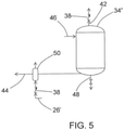
- the gas comprising ozone and oxygen is received from the liquid-gas separator 27 ( FIG. 3 ) on the ozone fluid flow path 26', and passes through a check valve 38, and then is dispensed into a tank 34'.
- the tank 34' can be an ozone storage tank, or it can be a material or surface to be treated with ozone such as a water supply tank or a fuel tank.
- ozone is introduced to the tank through manifold 40 and dispensed through conduit 44.
- the ozone can be delivered into a liquid water space in the tank 34' through a sparging manifold 40, and the bubbles of ozone contacting the water can promote a biocidal effect.
- a vent 42 with another check valve 38 allows for venting of pressure from gas buildup.
- Water can be dispensed from the storage tank 34 through conduit 44 to on-board water usage stations such as lavatory or galley facilities.
- a fill line 46 allows for initial charging of the water supply system with water, and a drain line 48 allows for draining of the system for cleaning and maintenance.
- the tank or component can be inerted by establishing conditions such that addition of ozone will not form a combustible mixture.
- Inerting the tank or component can involve removal of fuel and/or adding inert gas to the fuel tank or component. Ozone gas can then be added, e.g., through the manifold 40, held in the tank or component for biocidal effect, and then vented through vent 42.
- the ozone-containing anode effluent is introduced to a fuel tank that contains fuel and or water for in-situ sparging. In this case, it is envisioned to provide sufficient inert gas to the fuel tank ullage to avoid the formation of a combustible or explosive mixture of fuel and air.
- Additional protocols can be employed for cleaning of fuel tanks and systems, including but not limited to solvent cleaning to solubilize and remove lower volatility hydrocarbons, and purging a fuel tank or component with inert gas (such as produced at the cathode 14) and/or with air prior to or simultaneous with introduction of the ozone-containing gas to a fuel tank or fuel system component.
- the gas comprising ozone can be introduced to a gas-liquid contactor 50 disposed along conduit 44 serving as a water supply line, as shown in the example embodiment of FIG. 5 .
- a UV light source (not shown) can be used to dissociate ozone.
- a UV light source can be located at a point of use (e.g., between an ozone point of contact such as gas-liquid contactor 50 and a water dispenser) or can be disposed either in the tank 34' or at outlets from the tank 34' if the ozone introduction point is the tank 34' and water residence time in the tank is not sufficient for ozone to dissociate on its own over time.
- a point of use e.g., between an ozone point of contact such as gas-liquid contactor 50 and a water dispenser
- the electrochemical cell 10 can be operated continuously for delivery of ozone to the ozone storage or distribution system 34. However, continuous operation may not be necessary to meet system needs, and in some embodiments, the electrochemical cell 10 can be operated at to produce ozone at regular or irregular intervals. For example, in some embodiments, the electrochemical cell 10 can be operated in response to a predetermined quantity of water passing through a water storage tank (i.e., a degree of tank turnover). In some embodiments, the electrochemical cell 10 can be operated in response to detection of water passing through conduit 44 as a water supply line or through the gas-liquid contactor 50. In some embodiments, the electrochemical cell can be operated in response to a predetermined period of time such as a timer operating in the processor of controller 36.
- a predetermined quantity of water passing through a water storage tank i.e., a degree of tank turnover
- the electrochemical cell 10 can be operated in response to detection of water passing through conduit 44 as a water supply line or through the gas-liquid contactor 50.
- electrochemical cell is utilized exclusively for producing ozone and inert gas
- the electrochemical cell is also used for other purposes, namely the electrochemical cell is used to in an alternate mode to provide electric power for on-board power-consuming systems, as disclosed in the aforementioned US Patent Application Publication No. 2017/0331131A1 .
- fuel hydrogen is directed from a fuel source to the anode 16 where hydrogen molecules are split to form protons that are transported across the separator 12 to combine with oxygen at the cathode. Simultaneously, reduction and oxidation reactions exchange electrons at the electrodes, thereby producing electricity in an external circuit.
- Ozone is not produced by the electrochemical cell in this mode, and the water supply system usually can go untreated for short periods such as during an electricity-production mode.
- Embodiments in which these alternate modes of operation can be utilized include, for example, operating the system in alternate modes selected from a plurality of modes including a first mode of electrochemical oxygen production under normal aircraft operating conditions (e.g., in which an engine-mounted generator provides electrical power) and a second mode of electrochemical electricity production (e.g., in response to a demand for emergency electrical power such as resulting from failure of an engine-mounted generator) with ozone provided to an ozone storage or distribution 34.
- ODA can be produced at the cathode 14 in each of these alternate modes of operation.
Description
- The subject matter disclosed herein generally relates to vehicles comprising on-board systems for generating and providing inert gas to protected spaces and to providing anti-microbial treatment as well, and to corresponding methods.
- It is recognized that fuel vapors within fuel tanks become combustible or explosive in the presence of oxygen. An inerting system decreases the probability of combustion or explosion of flammable materials in a fuel tank by maintaining a chemically non-reactive or inerting gas, such as nitrogen-enriched air, in the fuel tank vapor space, also known as ullage. Three elements are required to initiate combustion or an explosion: an ignition source (e.g., heat), fuel, and oxygen. The oxidation of fuel may be prevented by reducing any one of these three elements. If the presence of an ignition source cannot be prevented within a fuel tank, then the tank may be made inert by: 1) reducing the oxygen concentration, 2) reducing the fuel concentration of the ullage to below the lower explosive limit (LEL), or 3) increasing the fuel concentration to above the upper explosive limit (UEL). Many systems reduce the risk of oxidation of fuel by reducing the oxygen concentration by introducing an inerting gas such as nitrogen-enriched air (NEA) (i.e., oxygen-depleted air or ODA) to the ullage, thereby displacing oxygen with a mixture of nitrogen and oxygen at target thresholds for avoiding explosion or combustion.
CN 109321937 A discloses an electrolytic ozone generator comprising an electrochemical cell, a cathode fluid chamber having a an air inlet, an anode fluid chamber with a water inlet, and an outlet for water and ozone. - It is known in the art to equip vehicles (e.g., aircraft, military vehicles, etc.) with onboard inerting gas generating systems, which supply nitrogen-enriched air to the vapor space (i.e., ullage) within the fuel tank. The nitrogen-enriched air has a substantially reduced oxygen content that reduces or eliminates oxidizing conditions within the fuel tank. Onboard inerting gas generating systems typically use membrane-based gas separators. Such separators contain a membrane that is permeable to oxygen and water molecules, but relatively impermeable to nitrogen molecules. A pressure differential across the membrane causes oxygen molecules from air on one side of the membrane to pass through the membrane, which forms oxygen-enriched air (OEA) on the low-pressure side of the membrane and nitrogen-enriched air (NEA) on the high-pressure side of the membrane. The requirement for a pressure differential necessitates a source of compressed or pressurized air. Another type of gas separator is based on an electrochemical cell such as a proton exchange membrane (PEM) electrochemical cell, which produces NEA by electrochemically generating protons for combination with oxygen to remove it from air.
- Additionally, protected spaces such as fuel tanks can be susceptible to microbial contamination, and other systems associated with or in proximity to protected spaces can also be susceptible to microbial contamination, including but not limited to water storage systems such as aircraft on-board water systems, which can be used to provide water for lavatory and other on-board facilities and for which microbial contamination can constitute a health risk.
- Accordingly, such on-board systems require substantial maintenance when the system is off-line to maintain safety and quality, and dedicated treatment systems such as chlorination or reverse osmosis systems can add additional payload, which in turn increases aircraft operating costs such as fuel consumption. As a result, many systems such as water supply systems or fuel systems can be susceptible to microbial contamination.
- In an aspect, vehicle having an inert gas-generating system according to
claim 1 is provided. - In some aspects, the ozone flow path can include a gas-liquid separator that receives a mixture comprising process water, oxygen, and ozone from the anode fluid flow path outlet and outputs a gas comprising ozone to the ozone storage or distribution system.
- In any one or combination of the foregoing aspects, the vehicle can further comprise a biologically active surface or material, wherein the ozone storage or distribution system can be in controllable operative fluid communication with the biologically active surface or material.
- In any one or combination of the foregoing aspects, the biologically active surface or material can include a water storage tank, or a water distribution system, or a fuel storage tank, or a fuel distribution system.
- [deleted]
- [deleted]
- In any one or combination of the foregoing aspects, the ozone storage or distribution system can be in controllable operative fluid communication with a liquid space or a vapor space of a water storage or supply tank.
- In any one or combination of the foregoing aspects, the ozone storage or distribution system can be in controllable operative fluid communication with a water supply flow path.
- In any one or combination of the foregoing aspects, the vehicle can further include a controller configured to direct a gas comprising ozone to the gas-liquid contactor in response to a flow of water on the water supply flow through the gas-liquid contactor.
- [deleted]
- In any one or combination of the foregoing aspects, the controller can be configured to operate in the first mode continuously or at intervals under normal operating conditions, and to operate in the second mode in response to a demand for emergency electrical power.
- Also disclosed is a method of treating a biologically active surface or material according to
claim 7. - In any one or combination of the foregoing aspects, the method can further include directing a fluid from the anode fluid flow path outlet to a gas-liquid separator, and directing the gas mixture comprising ozone from the cathode fluid flow path outlet and outputs a gas comprising ozone to the ozone storage or distribution system.
- In any one or combination of the foregoing aspects, the method can further include operating the electrochemical cell and directing the gas comprising ozone to the gas-liquid separator in response to a flow of water on the aircraft water supply flow through the gas-liquid separator.
- In any one or combination of the foregoing aspects, the biologically active surface or material can include a water storage tank, or a water distribution system, or a fuel storage tank, or a fuel distribution system.
- In any one or combination of the foregoing aspects, the biologically active surface or material can include a water storage tank, and the method includes sparging the gas comprising ozone through a liquid space in the water storage tank.
- In any one or combination of the foregoing aspects, the biologically active surface or material can include a water distribution system, and the method includes contacting gas flowing through the water distribution system with a stream of the gas comprising ozone.
- In any one or combination of the foregoing aspects, the biologically active surface or material can include a fuel storage tank or a fuel distribution system, and the method includes inerting the fuel storage tank or fuel distribution system, and adding the gas comprising ozone to the fuel tank or fuel distribution system.
- In any one or combination of the foregoing aspects, inerting the fuel storage tank or distribution system includes adding an inert gas to the fuel tank or fuel distribution system.
- In any one or combination of the foregoing aspects, the method can further include operating in alternate modes of operation selected from a plurality of modes including: (i) a first mode in which process water is directed to the anode fluid flow path inlet, electric power is directed from the power source to the electrochemical cell to provide a voltage difference between the anode and the cathode, and a gas comprising ozone is directed from the anode fluid flow path outlet to the ozone storage or distribution system; and (ii) a second mode in which hydrogen is directed from the hydrogen source to the anode fluid flow path inlet, electric power is directed from the electrochemical cell to the power sink, and the ozone storage or distribution system is isolated from the anode fluid flow path outlet.
- The following descriptions should not be considered limiting in any way. With reference to the accompanying drawings, like elements are numbered alike:
-
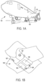
FIG. 1A is a schematic illustration of an aircraft that can incorporate various embodiments of the present disclosure; -
FIG. 1B is a schematic illustration of a bay section of the aircraft ofFIG. 1A ; -
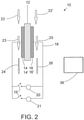
FIG. 2 is a schematic depiction an example embodiment of an electrochemical cell; -
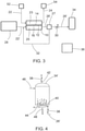
FIG. 3 is a schematic illustration of an example embodiment of an electrochemical inerting and treatment system; -
FIG. 4 is a schematic illustration of an example embodiment of ozone storage or distribution; and -
FIG. 5 is a schematic illustration of another example embodiment of ozone storage or distribution. - A detailed description of one or more embodiments of the disclosed apparatus and method are presented herein by way of exemplification and not limitation with reference to the Figures.
- Although shown and described above and below with respect to an aircraft, embodiments of the present disclosure are applicable to on-board systems for any type of vehicle . . For example, military vehicles, heavy machinery vehicles, sea craft, ships, submarines, etc., may benefit from implementation of embodiments of the present disclosure. For example, aircraft and other vehicles having fire suppression systems, emergency power systems, and other systems that may electrochemical systems as described herein may include the redundant systems described herein. As such, the present disclosure is not limited to application to aircraft, but rather aircraft are illustrated and described as example and explanatory embodiments for implementation of embodiments of the present disclosure.
- As shown in
FIGS. 1A-1B , an aircraft includes anaircraft body 101, which can include one ormore bays 103 beneath a center wing box. Thebay 103 can contain and/or support one or more components of theaircraft 101. For example, in some configurations, the aircraft can include environmental control systems (ECS) and/or on-board inerting gas generation systems (OBIGGS) within thebay 103. As shown inFIG. 1B , thebay 103 includesbay doors 105 that enable installation and access to one or more components (e.g., OBIGGS, ECS, etc.). During operation of environmental control systems and/or fuel inerting systems of the aircraft, air that is external to the aircraft can flow into one or moreram air inlets 107. The outside air may then be directed to various system components (e.g., environmental conditioning system (ECS) heat exchangers) within the aircraft. Some air may be exhausted through one or more ramair exhaust outlets 109. - Also shown in
FIG. 1A , the aircraft includes one ormore engines 111. Theengines 111 are typically mounted on thewings 112 of the aircraft and are connected to fuel tanks (not shown) in the wings, but may be located at other locations depending on the specific aircraft configuration. In some aircraft configurations, air can be bled from theengines 111 and supplied to OBIGGS, ECS, and/or other systems, as will be appreciated by those of skill in the art. - Referring now to
FIG. 2 , an electrochemical cell is schematically depicted. Theelectrochemical cell 10 comprises aseparator 12 that includes an ion transfer medium. As shown inFIG. 2 , theseparator 12 has acathode 14 disposed on one side and ananode 16 disposed on the other side.Cathode 14 andanode 16 can be fabricated from catalytic materials suitable for performing the needed electrochemical reaction (e.g., the oxygen-reduction reaction at the cathode and an oxidation reaction at the anode). Exemplary catalytic materials include, but are not limited to, nickel, platinum, palladium, rhodium, carbon, gold, tantalum, titanium, tungsten, ruthenium, iridium, osmium, zirconium, alloys thereof, and the like, as well as combinations of the foregoing materials.Cathode 14 andanode 16, including catalyst 14' and catalyst 16', are positioned adjacent to, and preferably in contact with theseparator 12 and can be porous metal layers deposited (e.g., by vapor deposition) onto theseparator 12, or can have structures comprising discrete catalytic particles adsorbed onto a porous substrate that is attached to theseparator 12. Alternatively, the catalyst particles can be deposited on high surface area powder materials (e.g., graphite or porous carbons or metal-oxide particles) and then these supported catalysts may be deposited directly onto theseparator 12 or onto a porous substrate that is attached to theseparator 12. Adhesion of the catalytic particles onto a substrate may be by any method including, but not limited to, spraying, dipping, painting, imbibing, vapor depositing, combinations of the foregoing methods, and the like. Alternately, the catalytic particles may be deposited directly onto opposing sides of theseparator 12. In either case, the cathode andanode layers anode layers - The
cathode 14 andanode 16 are controllably electrically connected byelectrical circuit 18 to a controllableelectric power system 20, which includes a power source (e.g., DC power rectified from AC power produced by a generator powered by a gas turbine engine used for propulsion or by an auxiliary power unit) a power sink 21. Theelectric power system 20 includes a connection to the electric power sink 21 (e.g., one or more electricity-consuming systems or components onboard the vehicle) with appropriate switching (e.g., switches 19), power conditioning, or power bus(es) for such on-board electricity-consuming systems or components, for optional operation in an alternative fuel cell mode. - With continued reference to
FIG. 2 , a cathode supplyfluid flow path 22 directs gas from an air source (not shown) into contact with thecathode 14. Oxygen is electrochemically depleted from air along the cathodefluid flow path 23, and can be exhausted to the atmosphere or discharged as nitrogen-enriched air (NEA) (i.e., oxygen-depleted air, ODA) to an inertinggas flow path 24 for delivery to an on-board fuel tank (not shown), or to a vehicle fire suppression system associated with an enclosed space (not shown), or controllably to either or both of a vehicle fuel tank or an on-board fire suppression system. An anodefluid flow path 25 is configured to controllably receive an anode supply fluid from an anode supply fluid flow path 22'. The anodefluid flow path 25 includes water when the electrochemical cell is operated in an electrolytic mode to produce protons at the anode for proton transfer across the separator 12 (e.g., a proton transfer medium such as a proton exchange membrane (PEM) electrolyte or phosphoric acid electrolyte). The anodefluid flow path 25 is configured to controllably also receive fuel (e.g., hydrogen). The protons formed at the anode are transported across theseparator 12 to thecathode 14, leaving oxygen and ozone on the anode fluid flow path, which is exhausted through ananode exhaust 26. The formation of ozone can be promoted with an elevated cell voltage (e.g. 2.1-3 Volts). Catalysts can also be formulated to favor promotion of the ozone-forming reaction. For example, the platinum-group metals (e.g., platinum, palladium, rhodium, iridium, rhuthenium, osmium) can produce ozone at the anode, and other catalysts can produce ozone at higher efficiencies, e.g., glassy carbon (e.g., boron-doped diamond), or metal oxide catalysts such as PbO2, Ta2O5. It is likely that both ozone (O3) and diatomic oxygen (O2) will be generated simultaneously, and that the ozone produced will be mixed in with oxygen and any process water beyond that needed for stoichiometric operation. Control of fluid flow along these flow paths can be provided through conduits and valves (not shown), which can be controlled by acontroller 36. The controller can include a microprocessor that is programmed with instructions for sending signals to carry out control of any of the operations described herein. - Exemplary materials from which the electrochemical proton transfer medium can be fabricated include proton-conducting ionomers and ion-exchange resins. Ion-exchange resins useful as proton conducting materials include hydrocarbon- and fluorocarbon-type resins. Fluorocarbon-type resins typically exhibit excellent resistance to oxidation by halogen, strong acids, and bases. One family of fluorocarbon-type resins having sulfonic acid group functionality is NAFION™ resins (commercially available from E. I. du Pont de Nemours and Company, Wilmington, Del.). Alternatively, instead of an ion-exchange membrane, the
separator 12 can be comprised of a liquid electrolyte, such as sulfuric or phosphoric acid, which may preferentially be absorbed in a porous-solid matrix material such as a layer of silicon carbide or a polymer than can absorb the liquid electrolyte, such as poly(benzoxazole). These types of alternative "membrane electrolytes" are well known and have been used in other electrochemical cells, such as phosphoric-acid fuel cells. - During operation of a proton transfer electrochemical cell in the electrolytic mode, water at the anode undergoes an electrolysis reaction according to the formulae:
H2O → ½O2 + 2H+ + 2e- (1a)
3H2O → O3 + 6H+ + 6e- (1b)
The electrons produced by this reaction are drawn fromelectrical circuit 18 powered byelectric power source 20 connecting the positively chargedanode 16 with thecathode 14. The hydrogen ions (i.e., protons) produced by this reaction migrate across theseparator 12, where they react at thecathode 14 with oxygen in thecathode flow path 23 to produce water according to the formula
½O2 + 2H+ + 2e- → H2O (2)
Removal of oxygen fromcathode flow path 23 produces nitrogen-enriched air exiting the region of thecathode 14. The oxygen and ozone evolved at theanode 16 by the reaction of formula (1) is discharged asanode exhaust 26. - During operation of a proton transfer electrochemical cell in a fuel cell mode, fuel (e.g., hydrogen) at the anode undergoes an electrochemical oxidation according to the formula
H2 → 2H+ + 2e (3)
The electrons produced by this reaction flow throughelectrical circuit 18 to provide electric power to the electric power sink 21. The hydrogen ions (i.e., protons) produced by this reaction migrate across theseparator 12, where they react at thecathode 14 with oxygen in thecathode flow path 23 to produce water according to the formula (2).
½O2 + 2H+ + 2e- → H2O (2)
Removal of oxygen fromcathode flow path 23 produces nitrogen-enriched air exiting the region of thecathode 14. - As mentioned above, the electrolysis reaction occurring at the positively charged
anode 16 requires water, and the ionic polymers used for a PEM electrolyte perform more effectively in the presence of water. Accordingly, in some embodiments, a PEM membrane electrolyte is saturated with water or water vapor. Although the reactions (1a-b) and (2) are stoichiometrically balanced with respect to water so that there is no net consumption of water, in practice some amount of moisture will be removed through thecathode exhaust 24 and/or the anode exhaust 26 (either entrained or evaporated into the exiting gas streams). Accordingly, in some exemplary embodiments, water from a water source is circulated past theanode 16 along an anode fluid flow path (and optionally also past the cathode 14). Such water circulation can also provide cooling for the electrochemical cells. In some exemplary embodiments, water can be provided at the anode from humidity in air along an anode fluid flow path in fluid communication with the anode. In other embodiments, the water produced atcathode 14 can be captured and recycled to anode 16 (e.g., through a water circulation loop, not shown). It should also be noted that, although the embodiments are contemplated where a single electrochemical cell is employed, in practice multiple electrochemical cells will be electrically connected in series with fluid flow to the multiple cathode and anode flow paths routed through manifold assemblies. - An example embodiment of an aircraft inert gas-generating system that produces ozone from an
electrochemical cell 10 is schematically shown inFIG. 3 . As shown inFIG. 3 , water from aprocess water source 28 is directed (e.g., by a pump, not shown) along the anode supply fluid flow path 22' to the anodefluid flow path 25, where it is electrolyzed at theanode 16 to form protons, ozone, and oxygen. The protons are transported across theseparator 12 to thecathode 14, where they combine with oxygen from airflow along the cathodefluid flow path 23 to form water. Removal of the protons from the anodefluid flow path 25 leaves ozone and oxygen gas on the anode fluid flow path, which is discharged asanode exhaust 26 to an ozone fluid flow path 26'. - As further shown in
FIG. 3 , the ozone fluid flow path 26' includes a gas-liquid separator 27 and aflow control valve 30. Although water is consumed at the anode by electrolysis, the gas exiting asanode exhaust 26 can include water vapor or entrained liquid water from excess water on the anodefluid flow path 25 such as from a liquid water circulation loop. The gas-liquid separator 27 can include a tank with a liquid space and a vapor space inside, allowing for liquid water to be removed from the liquid space and transported back to theelectrochemical cell 10 throughwater return conduit 32. Heat may be provided to promote evolution of ozone gas from ozone dissolved in the process water. Additional gas-liquid separators and/or water removal devices can be used such as a coalescing filter, vortex gas-liquid separator, electrochemical dryer, or membrane separator, to remove moisture from the ozone if needed (e.g., moisture removal may be needed if the ozone is used to treat moisture-sensitive areas such as fuel tanks or fuel systems). Additional gas-liquid separators can include coalescing filters, vortex gas-liquid separators, or membrane separators, and can be located for example along the fluid flow path 26'. Examples of water removal devices include but are not limited to a desiccant (including a desiccant wheel), a membrane drier (see, e.g.,US 2019/0001264A1 ), a condensing heat exchanger operated at elevated pressure (see, e.g.,US patent application serial no. 16,149,736 US patent application serial no. 16,127,980 US20190001264A1 ), and can be used to remove water vapor and entrained liquid water. - As further shown in
FIG. 3 , the electrochemical cell orcell stack 10 generates an inerting gas on the cathodefluid flow path 23 by depleting oxygen to produce oxygen-depleted air (ODA), also known as nitrogen-enriched air (NEA) at thecathode 14 that is directed to a protected space 54 (e.g., a fuel tank ullage space, a cargo hold, or an equipment bay). As shown inFIG. 3 , an air source 52 (e.g., ram air, compressor bleed, blower) is directed to the cathodefluid flow path 23 where oxygen is depleted by electrochemical reactions with protons that have crossed theseparator 12 as well as electrons from an external circuit (not shown) to form water at thecathode 14. The ODA thereby produced is directed to a protectedspace 54 such as an ullage space in in the aircraft fuel tanks as disclosed or other protectedspace 54. The inerting gas flow path (cathode exhaust 24) can include additional components (not shown) such as flow control valve(s), a pressure regulator or other pressure control device, and water removal device(s) such as a heat exchanger condenser, a membrane drier or other water removal device(s), or a filter or other particulate or contaminant removal devices. Additional information regarding the electrochemical production of ODA can be found inU.S. Patent 9,963,792 US Patent Application Publication No. 2017/0331131A1 , andUS Patent Application Serial No. 16/029,024 . - As further shown in
FIG. 3 , the gas comprising ozone on the ozone flow path 26' is delivered to an ozone storage ordistribution system 34, where it can stored and/or distributed provide a biocidal effect for disinfecting or otherwise treating organic contaminants at a biologically-active material or surface such as a water supply tank, a water distribution system, grey-water holding tank, a fuel tank or a fuel distribution system. Ozone itself is a strong oxidant that can provide the biocidal effect, and can also decompose to form hydroxyl or peroxyl radicals that are also reactive with organic contaminants. Microbial contamination of water or fuel system components can lead to formation of a sludge-like biomass that can clog filters, occlude conduit lines, and lead to unplanned system failure. Acidic byproducts of metabolism of microbes can alter the pH of fuel or water tanks and conduits and promote corrosion or scale formation. In fuel systems, microbial growth can be promoted by the introduction of water vapor to a fuel tank often in the form of vapor through a vent. Aircraft fuel tanks can be subject to significant incoming moisture during descent, as moisture-containing outside air at a pressure greater than that of pressure in the fuel tank enters through one or more fuel system vents. By a similar pathway, microbes and spores can find their way into fuel tanks. The condensation of water vapor in the fuel tank causes the liquid water to come into contact with the fuel. Water and fuel are immiscible, so the water settles at the bottom of the tank, where the interface of the water and fuel can provide an environment for microbial growth involving fungus or bacteria, or both fungus and bacteria. - Additional detail regarding the storage or distribution of the gas comprising ozone is shown in an example embodiment of
FIG. 4 . As shown inFIG. 4 , the gas comprising ozone and oxygen is received from the liquid-gas separator 27 (FIG. 3 ) on the ozone fluid flow path 26', and passes through acheck valve 38, and then is dispensed into a tank 34'. The tank 34' can be an ozone storage tank, or it can be a material or surface to be treated with ozone such as a water supply tank or a fuel tank. In the case of an ozone storage tank, ozone is introduced to the tank throughmanifold 40 and dispensed throughconduit 44. In the case of a water supply tank, the ozone can be delivered into a liquid water space in the tank 34' through asparging manifold 40, and the bubbles of ozone contacting the water can promote a biocidal effect. Avent 42 with anothercheck valve 38 allows for venting of pressure from gas buildup. Water can be dispensed from thestorage tank 34 throughconduit 44 to on-board water usage stations such as lavatory or galley facilities. Afill line 46 allows for initial charging of the water supply system with water, and adrain line 48 allows for draining of the system for cleaning and maintenance. In the case of treatment of a fuel tank or fuel system component, the tank or component can be inerted by establishing conditions such that addition of ozone will not form a combustible mixture. Inerting the tank or component can involve removal of fuel and/or adding inert gas to the fuel tank or component. Ozone gas can then be added, e.g., through the manifold 40, held in the tank or component for biocidal effect, and then vented throughvent 42. In another embodiment, the ozone-containing anode effluent is introduced to a fuel tank that contains fuel and or water for in-situ sparging. In this case, it is envisioned to provide sufficient inert gas to the fuel tank ullage to avoid the formation of a combustible or explosive mixture of fuel and air. Additional protocols can be employed for cleaning of fuel tanks and systems, including but not limited to solvent cleaning to solubilize and remove lower volatility hydrocarbons, and purging a fuel tank or component with inert gas (such as produced at the cathode 14) and/or with air prior to or simultaneous with introduction of the ozone-containing gas to a fuel tank or fuel system component. - In another embodiment, instead of treating a water supply system by introducing ozone directly into a water supply tank such as tank 34', the gas comprising ozone can be introduced to a gas-
liquid contactor 50 disposed alongconduit 44 serving as a water supply line, as shown in the example embodiment ofFIG. 5 . This can provide a technical effect of promoting anti-microbial action only in water as it is being dispensed. However, ozone should not reach consumers of water from a treated water system, and in some embodiments, a UV light source (not shown) can be used to dissociate ozone. A UV light source can be located at a point of use (e.g., between an ozone point of contact such as gas-liquid contactor 50 and a water dispenser) or can be disposed either in the tank 34' or at outlets from the tank 34' if the ozone introduction point is the tank 34' and water residence time in the tank is not sufficient for ozone to dissociate on its own over time. - In some embodiments, the
electrochemical cell 10 can be operated continuously for delivery of ozone to the ozone storage ordistribution system 34. However, continuous operation may not be necessary to meet system needs, and in some embodiments, theelectrochemical cell 10 can be operated at to produce ozone at regular or irregular intervals. For example, in some embodiments, theelectrochemical cell 10 can be operated in response to a predetermined quantity of water passing through a water storage tank (i.e., a degree of tank turnover). In some embodiments, theelectrochemical cell 10 can be operated in response to detection of water passing throughconduit 44 as a water supply line or through the gas-liquid contactor 50. In some embodiments, the electrochemical cell can be operated in response to a predetermined period of time such as a timer operating in the processor ofcontroller 36. - Although this disclosure includes embodiments where an electrochemical cell is utilized exclusively for producing ozone and inert gas, the electrochemical cell is also used for other purposes, namely the electrochemical cell is used to in an alternate mode to provide electric power for on-board power-consuming systems, as disclosed in the aforementioned
US Patent Application Publication No. 2017/0331131A1 . In this mode, fuel hydrogen) is directed from a fuel source to theanode 16 where hydrogen molecules are split to form protons that are transported across theseparator 12 to combine with oxygen at the cathode. Simultaneously, reduction and oxidation reactions exchange electrons at the electrodes, thereby producing electricity in an external circuit. Ozone is not produced by the electrochemical cell in this mode, and the water supply system usually can go untreated for short periods such as during an electricity-production mode. Embodiments in which these alternate modes of operation can be utilized include, for example, operating the system in alternate modes selected from a plurality of modes including a first mode of electrochemical oxygen production under normal aircraft operating conditions (e.g., in which an engine-mounted generator provides electrical power) and a second mode of electrochemical electricity production (e.g., in response to a demand for emergency electrical power such as resulting from failure of an engine-mounted generator) with ozone provided to an ozone storage ordistribution 34. ODA can be produced at thecathode 14 in each of these alternate modes of operation. - The term "about" is intended to include the degree of error associated with measurement of the particular quantity based upon the equipment available at the time of filing the application.
- As used herein, the singular forms "a", "an", "the", or "any" are intended to include the plural forms as well, unless the context clearly indicates otherwise. It will be further understood that the terms "comprises" and/or "comprising," when used in this specification, specify the presence of stated features, integers, steps, operations, elements, and/or components, but do not preclude the presence or addition of one or more other features, integers, steps, operations, element components, and/or groups thereof.
- While the present disclosure has been described with reference to an exemplary embodiment or embodiments, it will be understood by those skilled in the art that various changes may be made and equivalents may be substituted for elements thereof without departing from the scope of the present disclosure. In addition, many modifications may be made to adapt a particular situation or material to the teachings of the invention as defined by the claims without departing from the scope of the invention. Therefore, it is intended that the present disclosure not be limited to the particular embodiment disclosed as the best mode contemplated for carrying out this present disclosure, but that the present disclosure will include all embodiments falling within the scope of the claims.
Claims (13)
- A vehicle (101) comprising an on-board inert gas-generating system, the system comprising:a protected space (54) selected from a fuel tank ullage space, a cargo hold, or an equipment bay;an electrochemical cell (10) comprising a cathode (14) and an anode (16) separated by a separator (12) comprising a proton transfer medium;a cathode fluid flow path (23) in operative fluid communication with the cathode between a cathode fluid flow path inlet and a cathode fluid flow path outlet;a cathode supply fluid flow path (22) between an air source (52) and the cathode fluid flow path inlet, and an inerting gas flow path (24) in operative fluid communication with the cathode fluid flow path outlet and the protected space;an anode fluid flow path (25) in operative fluid communication with the anode between an anode fluid flow path inlet and an anode fluid flow path outlet;an anode supply fluid flow path (22') between a water source (28) and the anode fluid flow path inlet, and an ozone flow path (26') in operative fluid communication with the anode fluid flow path outlet and an ozone storage or distribution system (34); andan electrical connection (18) between a power source (20) and the electrochemical cell;a hydrogen source in operative fluid communication with the anode fluid flow path inlet;an electrical connection (18) between the electrochemical cell (10) and a power sink (21); anda controller (36) configured to operate the system in alternate modes of operation selected from a plurality of modes including:a first mode in which process water is directed to the anode fluid flow path inlet, electric power is directed from the power source to the electrochemical cell to provide a voltage difference between the anode and the cathode, and a gas comprising ozone is directed from the anode fluid flow path outlet to the ozone storage or distribution system, anda second mode in which hydrogen is directed from the hydrogen source to the anode fluid flow path inlet, electric power is directed from the electrochemical cell to the power sink, and the ozone storage or distribution system is isolated from the anode fluid flow path outlet.
- The vehicle of claim 1, wherein the ozone flow path includes a gas-liquid separator (27) that receives a mixture comprising process water, oxygen, and ozone from the anode fluid flow path outlet and outputs a gas comprising ozone to the ozone storage or distribution system.
- The vehicle of claim 1, further comprising a biologically active surface or material, wherein the ozone storage or distribution system is in controllable operative fluid communication with the biologically active surface or material, and optionally wherein the biologically active surface or material includes a water storage tank, or a water distribution system, or a fuel storage tank, or a fuel distribution system.
- The vehicle of claim 3, wherein the ozone storage or distribution system is in controllable operative fluid communication with a liquid space or a vapor space of a water storage or supply tank, and/or wherein the ozone storage or distribution system is in controllable operative fluid communication with a water supply flow path.
- The vehicle of claim 4, further comprising a controller (36) configured direct a gas comprising ozone to the gas-liquid contactor in response to a flow of water on the water supply flow through the gas-liquid contactor.
- The vehicle of claim 6, the controller is configured to operate in the first mode continuously or at intervals under normal operating conditions, and to operate in the second mode in response to a demand for emergency electrical power.
- A method of treating a biologically active surface or material and inerting a protected space on-board the vehicle according to claim 1, comprising:delivering water to the anode of the electrochemical cell;applying a voltage difference between the anode and the cathode to electrolyze water at the anode to form a mixture comprising protons and ozone;transferring the ozone to the ozone storage or distribution system, and transferring ozone from the ozone storage or distribution system to the biologically active surface or material;delivering air to the cathode and transferring the protons across the separator to the cathode, and reducing oxygen at the cathode to generate oxygen-depleted air;directing the oxygen-depleted air from the cathode of the electrochemical cell to the protected space.
- The method of claim 7, comprising directing a fluid from the anode fluid flow path outlet to a gas-liquid separator, and directing the gas mixture comprising ozone from the cathode fluid flow path outlet and outputs a gas comprising ozone to the ozone storage or distribution system.
- The method of claim 8, further comprising operating the electrochemical cell and directing the gas comprising ozone to the gas-liquid separator in response to a flow of water on the aircraft water supply flow through the gas-liquid separator.
- The method of claim 7, 8, or 9, wherein the biologically active surface or material includes a water storage tank, or a water distribution system, or a fuel storage tank, or a fuel distribution system.
- The method of claim 10, wherein the biologically active surface or material includes a water storage tank, and the method includes sparging the gas comprising ozone through a liquid space in the water storage tank, or wherein the biologically active surface or material includes a water distribution system, and the method includes contacting gas flowing through the water distribution system with a stream of the gas comprising ozone, or wherein the biologically active surface or material includes a fuel storage tank or a fuel distribution system, and the method includes inerting the fuel storage tank or fuel distribution system, and adding the gas comprising ozone to the fuel tank or fuel distribution system.
- The method of claim 11, wherein inerting the fuel storage tank or distribution system includes adding an inert gas to the fuel tank or fuel distribution system.
- The method of any of claims 7 to 12, further comprising:
operating in alternate modes of operation selected from a plurality of modes including:a first mode in which process water is directed to the anode fluid flow path inlet, electric power is directed from the power source to the electrochemical cell to provide a voltage difference between the anode and the cathode, and a gas comprising ozone is directed from the anode fluid flow path outlet to the ozone storage or distribution system, anda second mode in which hydrogen is directed from the hydrogen source to the anode fluid flow path inlet, electric power is directed from the electrochemical cell to the power sink, and the ozone storage or distribution system is isolated from the anode fluid flow path outlet.
Applications Claiming Priority (1)
| Application Number | Priority Date | Filing Date | Title |
|---|---|---|---|
| US16/375,609 US20200316521A1 (en) | 2019-04-04 | 2019-04-04 | Electrochemical anti-microbial treatment and inert gas generating system and method |
Publications (2)
| Publication Number | Publication Date |
|---|---|
| EP3719178A1 EP3719178A1 (en) | 2020-10-07 |
| EP3719178B1 true EP3719178B1 (en) | 2022-03-16 |
Family
ID=68581649
Family Applications (1)
| Application Number | Title | Priority Date | Filing Date |
|---|---|---|---|
| EP19209251.8A Active EP3719178B1 (en) | 2019-04-04 | 2019-11-14 | Electrochemical anti-microbial treatment and inert gas generating system and method |
Country Status (2)
| Country | Link |
|---|---|
| US (1) | US20200316521A1 (en) |
| EP (1) | EP3719178B1 (en) |
Families Citing this family (1)
| Publication number | Priority date | Publication date | Assignee | Title |
|---|---|---|---|---|
| US20230076753A1 (en) * | 2021-09-02 | 2023-03-09 | Brian Frankie | Liquified natural gas processing cold box with internal refrigerant storage |
Family Cites Families (5)
| Publication number | Priority date | Publication date | Assignee | Title |
|---|---|---|---|---|
| WO2016116898A1 (en) * | 2015-01-22 | 2016-07-28 | Zodiac Aerotechnics | Fuel cell devices for fire prevention on-board aircraft |
| US9963792B2 (en) | 2015-12-15 | 2018-05-08 | Hamilton Sundstrand Corporation | Electrochemical gas separator for combustion prevention and suppression |
| US10312536B2 (en) | 2016-05-10 | 2019-06-04 | Hamilton Sundstrand Corporation | On-board aircraft electrochemical system |
| US10532311B2 (en) | 2017-06-30 | 2020-01-14 | Hamilton Sundstrand Corporation | Inert gas generation with dehumidification |
| CN109321937A (en) * | 2018-11-29 | 2019-02-12 | 深圳康诚博信科技有限公司 | A kind of ozone generating-device |
-
2019
- 2019-04-04 US US16/375,609 patent/US20200316521A1/en not_active Abandoned
- 2019-11-14 EP EP19209251.8A patent/EP3719178B1/en active Active
Also Published As
| Publication number | Publication date |
|---|---|
| US20200316521A1 (en) | 2020-10-08 |
| EP3719178A1 (en) | 2020-10-07 |
Similar Documents
| Publication | Publication Date | Title |
|---|---|---|
| US11258083B2 (en) | On-board aircraft electrochemical system | |
| EP3263187B1 (en) | On-board aircraft electrochemical inert gas generation system | |
| US11260346B2 (en) | Inerting system | |
| EP3718902A1 (en) | Water systems for onboard inerting systems of vehicles | |
| EP3718606B1 (en) | Water systems for onboard inerting systems of vehicles | |
| EP3719178B1 (en) | Electrochemical anti-microbial treatment and inert gas generating system and method | |
| US11872424B2 (en) | Process water gas management of electrolyzer system with membrane | |
| EP3719173A1 (en) | Process water thermal management of electrochemical inert gas generating system | |
| EP3800281A1 (en) | Process water gas management of electrolyzer system with pressure differential | |
| US20220355947A1 (en) | Electrochemical inert gas and power generating system and method | |
| EP3719177B1 (en) | Thermally-managed electrochemical inert gas generating system and method | |
| US11491443B2 (en) | Process water gas management of electrochemical inert gas generating system | |
| EP3800280A1 (en) | Process water gas management of electrochemical inert gas generating system | |
| EP3718903B1 (en) | Water systems for onboard inerting systems of vehicles | |
| EP3549641B1 (en) | Fuel tank inerting system | |
| EP3800127B1 (en) | Fuel tank inerting system and method | |
| EP3719175A1 (en) | Catalytic electrochemical inert gas and power generating system and method |
Legal Events
| Date | Code | Title | Description |
|---|---|---|---|
| PUAI | Public reference made under article 153(3) epc to a published international application that has entered the european phase |
Free format text: ORIGINAL CODE: 0009012 |
|
| STAA | Information on the status of an ep patent application or granted ep patent |
Free format text: STATUS: THE APPLICATION HAS BEEN PUBLISHED |
|
| AK | Designated contracting states |
Kind code of ref document: A1 Designated state(s): AL AT BE BG CH CY CZ DE DK EE ES FI FR GB GR HR HU IE IS IT LI LT LU LV MC MK MT NL NO PL PT RO RS SE SI SK SM TR |
|
| AX | Request for extension of the european patent |
Extension state: BA ME |
|
| STAA | Information on the status of an ep patent application or granted ep patent |
Free format text: STATUS: REQUEST FOR EXAMINATION WAS MADE |
|
| 17P | Request for examination filed |
Effective date: 20210407 |
|
| RBV | Designated contracting states (corrected) |
Designated state(s): AL AT BE BG CH CY CZ DE DK EE ES FI FR GB GR HR HU IE IS IT LI LT LU LV MC MK MT NL NO PL PT RO RS SE SI SK SM TR |
|
| STAA | Information on the status of an ep patent application or granted ep patent |
Free format text: STATUS: EXAMINATION IS IN PROGRESS |
|
| 17Q | First examination report despatched |
Effective date: 20210518 |
|
| GRAP | Despatch of communication of intention to grant a patent |
Free format text: ORIGINAL CODE: EPIDOSNIGR1 |
|
| STAA | Information on the status of an ep patent application or granted ep patent |
Free format text: STATUS: GRANT OF PATENT IS INTENDED |
|
| RIC1 | Information provided on ipc code assigned before grant |
Ipc: A62C 99/00 20100101ALI20210923BHEP Ipc: A62C 3/08 20060101ALI20210923BHEP Ipc: A62C 3/06 20060101ALI20210923BHEP Ipc: C25B 15/02 20210101ALI20210923BHEP Ipc: C25B 1/24 20210101ALI20210923BHEP Ipc: C25B 1/13 20060101AFI20210923BHEP |
|
| INTG | Intention to grant announced |
Effective date: 20211022 |
|
| GRAS | Grant fee paid |
Free format text: ORIGINAL CODE: EPIDOSNIGR3 |
|
| GRAA | (expected) grant |
Free format text: ORIGINAL CODE: 0009210 |
|
| STAA | Information on the status of an ep patent application or granted ep patent |
Free format text: STATUS: THE PATENT HAS BEEN GRANTED |
|
| AK | Designated contracting states |
Kind code of ref document: B1 Designated state(s): AL AT BE BG CH CY CZ DE DK EE ES FI FR GB GR HR HU IE IS IT LI LT LU LV MC MK MT NL NO PL PT RO RS SE SI SK SM TR |
|
| REG | Reference to a national code |
Ref country code: GB Ref legal event code: FG4D |
|
| REG | Reference to a national code |
Ref country code: CH Ref legal event code: EP |
|
| REG | Reference to a national code |
Ref country code: DE Ref legal event code: R096 Ref document number: 602019012560 Country of ref document: DE |
|
| REG | Reference to a national code |
Ref country code: IE Ref legal event code: FG4D |
|
| REG | Reference to a national code |
Ref country code: AT Ref legal event code: REF Ref document number: 1475927 Country of ref document: AT Kind code of ref document: T Effective date: 20220415 |
|
| REG | Reference to a national code |
Ref country code: LT Ref legal event code: MG9D |
|
| REG | Reference to a national code |
Ref country code: NL Ref legal event code: MP Effective date: 20220316 |
|
| PG25 | Lapsed in a contracting state [announced via postgrant information from national office to epo] |
Ref country code: SE Free format text: LAPSE BECAUSE OF FAILURE TO SUBMIT A TRANSLATION OF THE DESCRIPTION OR TO PAY THE FEE WITHIN THE PRESCRIBED TIME-LIMIT Effective date: 20220316 Ref country code: RS Free format text: LAPSE BECAUSE OF FAILURE TO SUBMIT A TRANSLATION OF THE DESCRIPTION OR TO PAY THE FEE WITHIN THE PRESCRIBED TIME-LIMIT Effective date: 20220316 Ref country code: NO Free format text: LAPSE BECAUSE OF FAILURE TO SUBMIT A TRANSLATION OF THE DESCRIPTION OR TO PAY THE FEE WITHIN THE PRESCRIBED TIME-LIMIT Effective date: 20220616 Ref country code: LT Free format text: LAPSE BECAUSE OF FAILURE TO SUBMIT A TRANSLATION OF THE DESCRIPTION OR TO PAY THE FEE WITHIN THE PRESCRIBED TIME-LIMIT Effective date: 20220316 Ref country code: HR Free format text: LAPSE BECAUSE OF FAILURE TO SUBMIT A TRANSLATION OF THE DESCRIPTION OR TO PAY THE FEE WITHIN THE PRESCRIBED TIME-LIMIT Effective date: 20220316 Ref country code: BG Free format text: LAPSE BECAUSE OF FAILURE TO SUBMIT A TRANSLATION OF THE DESCRIPTION OR TO PAY THE FEE WITHIN THE PRESCRIBED TIME-LIMIT Effective date: 20220616 |
|
| REG | Reference to a national code |
Ref country code: AT Ref legal event code: MK05 Ref document number: 1475927 Country of ref document: AT Kind code of ref document: T Effective date: 20220316 |
|
| PG25 | Lapsed in a contracting state [announced via postgrant information from national office to epo] |
Ref country code: LV Free format text: LAPSE BECAUSE OF FAILURE TO SUBMIT A TRANSLATION OF THE DESCRIPTION OR TO PAY THE FEE WITHIN THE PRESCRIBED TIME-LIMIT Effective date: 20220316 Ref country code: GR Free format text: LAPSE BECAUSE OF FAILURE TO SUBMIT A TRANSLATION OF THE DESCRIPTION OR TO PAY THE FEE WITHIN THE PRESCRIBED TIME-LIMIT Effective date: 20220617 Ref country code: FI Free format text: LAPSE BECAUSE OF FAILURE TO SUBMIT A TRANSLATION OF THE DESCRIPTION OR TO PAY THE FEE WITHIN THE PRESCRIBED TIME-LIMIT Effective date: 20220316 |
|
| PG25 | Lapsed in a contracting state [announced via postgrant information from national office to epo] |
Ref country code: NL Free format text: LAPSE BECAUSE OF FAILURE TO SUBMIT A TRANSLATION OF THE DESCRIPTION OR TO PAY THE FEE WITHIN THE PRESCRIBED TIME-LIMIT Effective date: 20220316 |
|
| PG25 | Lapsed in a contracting state [announced via postgrant information from national office to epo] |
Ref country code: SM Free format text: LAPSE BECAUSE OF FAILURE TO SUBMIT A TRANSLATION OF THE DESCRIPTION OR TO PAY THE FEE WITHIN THE PRESCRIBED TIME-LIMIT Effective date: 20220316 Ref country code: SK Free format text: LAPSE BECAUSE OF FAILURE TO SUBMIT A TRANSLATION OF THE DESCRIPTION OR TO PAY THE FEE WITHIN THE PRESCRIBED TIME-LIMIT Effective date: 20220316 Ref country code: RO Free format text: LAPSE BECAUSE OF FAILURE TO SUBMIT A TRANSLATION OF THE DESCRIPTION OR TO PAY THE FEE WITHIN THE PRESCRIBED TIME-LIMIT Effective date: 20220316 Ref country code: PT Free format text: LAPSE BECAUSE OF FAILURE TO SUBMIT A TRANSLATION OF THE DESCRIPTION OR TO PAY THE FEE WITHIN THE PRESCRIBED TIME-LIMIT Effective date: 20220718 Ref country code: ES Free format text: LAPSE BECAUSE OF FAILURE TO SUBMIT A TRANSLATION OF THE DESCRIPTION OR TO PAY THE FEE WITHIN THE PRESCRIBED TIME-LIMIT Effective date: 20220316 Ref country code: EE Free format text: LAPSE BECAUSE OF FAILURE TO SUBMIT A TRANSLATION OF THE DESCRIPTION OR TO PAY THE FEE WITHIN THE PRESCRIBED TIME-LIMIT Effective date: 20220316 Ref country code: CZ Free format text: LAPSE BECAUSE OF FAILURE TO SUBMIT A TRANSLATION OF THE DESCRIPTION OR TO PAY THE FEE WITHIN THE PRESCRIBED TIME-LIMIT Effective date: 20220316 Ref country code: AT Free format text: LAPSE BECAUSE OF FAILURE TO SUBMIT A TRANSLATION OF THE DESCRIPTION OR TO PAY THE FEE WITHIN THE PRESCRIBED TIME-LIMIT Effective date: 20220316 |
|
| PG25 | Lapsed in a contracting state [announced via postgrant information from national office to epo] |
Ref country code: PL Free format text: LAPSE BECAUSE OF FAILURE TO SUBMIT A TRANSLATION OF THE DESCRIPTION OR TO PAY THE FEE WITHIN THE PRESCRIBED TIME-LIMIT Effective date: 20220316 Ref country code: IS Free format text: LAPSE BECAUSE OF FAILURE TO SUBMIT A TRANSLATION OF THE DESCRIPTION OR TO PAY THE FEE WITHIN THE PRESCRIBED TIME-LIMIT Effective date: 20220716 Ref country code: AL Free format text: LAPSE BECAUSE OF FAILURE TO SUBMIT A TRANSLATION OF THE DESCRIPTION OR TO PAY THE FEE WITHIN THE PRESCRIBED TIME-LIMIT Effective date: 20220316 |
|
| REG | Reference to a national code |
Ref country code: DE Ref legal event code: R097 Ref document number: 602019012560 Country of ref document: DE |
|
| PLBE | No opposition filed within time limit |
Free format text: ORIGINAL CODE: 0009261 |
|
| STAA | Information on the status of an ep patent application or granted ep patent |
Free format text: STATUS: NO OPPOSITION FILED WITHIN TIME LIMIT |
|
| PG25 | Lapsed in a contracting state [announced via postgrant information from national office to epo] |
Ref country code: DK Free format text: LAPSE BECAUSE OF FAILURE TO SUBMIT A TRANSLATION OF THE DESCRIPTION OR TO PAY THE FEE WITHIN THE PRESCRIBED TIME-LIMIT Effective date: 20220316 |
|
| 26N | No opposition filed |
Effective date: 20221219 |
|
| PG25 | Lapsed in a contracting state [announced via postgrant information from national office to epo] |
Ref country code: SI Free format text: LAPSE BECAUSE OF FAILURE TO SUBMIT A TRANSLATION OF THE DESCRIPTION OR TO PAY THE FEE WITHIN THE PRESCRIBED TIME-LIMIT Effective date: 20220316 |
|
| PG25 | Lapsed in a contracting state [announced via postgrant information from national office to epo] |
Ref country code: MC Free format text: LAPSE BECAUSE OF FAILURE TO SUBMIT A TRANSLATION OF THE DESCRIPTION OR TO PAY THE FEE WITHIN THE PRESCRIBED TIME-LIMIT Effective date: 20220316 |
|
| REG | Reference to a national code |
Ref country code: CH Ref legal event code: PL |
|
| P01 | Opt-out of the competence of the unified patent court (upc) registered |
Effective date: 20230603 |
|
| REG | Reference to a national code |
Ref country code: BE Ref legal event code: MM Effective date: 20221130 |
|
| PG25 | Lapsed in a contracting state [announced via postgrant information from national office to epo] |
Ref country code: LI Free format text: LAPSE BECAUSE OF NON-PAYMENT OF DUE FEES Effective date: 20221130 Ref country code: IT Free format text: LAPSE BECAUSE OF FAILURE TO SUBMIT A TRANSLATION OF THE DESCRIPTION OR TO PAY THE FEE WITHIN THE PRESCRIBED TIME-LIMIT Effective date: 20220316 Ref country code: CH Free format text: LAPSE BECAUSE OF NON-PAYMENT OF DUE FEES Effective date: 20221130 |
|
| PG25 | Lapsed in a contracting state [announced via postgrant information from national office to epo] |
Ref country code: LU Free format text: LAPSE BECAUSE OF NON-PAYMENT OF DUE FEES Effective date: 20221114 |
|
| PG25 | Lapsed in a contracting state [announced via postgrant information from national office to epo] |
Ref country code: IE Free format text: LAPSE BECAUSE OF NON-PAYMENT OF DUE FEES Effective date: 20221114 |
|
| PG25 | Lapsed in a contracting state [announced via postgrant information from national office to epo] |
Ref country code: BE Free format text: LAPSE BECAUSE OF NON-PAYMENT OF DUE FEES Effective date: 20221130 |
|
| PGFP | Annual fee paid to national office [announced via postgrant information from national office to epo] |
Ref country code: GB Payment date: 20231019 Year of fee payment: 5 |
|
| PGFP | Annual fee paid to national office [announced via postgrant information from national office to epo] |
Ref country code: FR Payment date: 20231019 Year of fee payment: 5 Ref country code: DE Payment date: 20231019 Year of fee payment: 5 |