EP3718976A1 - Device for manufacturing lass body, method for manufacturing glass body, soot conveyance mechanism, and soot heating mechanism - Google Patents
Device for manufacturing lass body, method for manufacturing glass body, soot conveyance mechanism, and soot heating mechanism Download PDFInfo
- Publication number
- EP3718976A1 EP3718976A1 EP18884628.1A EP18884628A EP3718976A1 EP 3718976 A1 EP3718976 A1 EP 3718976A1 EP 18884628 A EP18884628 A EP 18884628A EP 3718976 A1 EP3718976 A1 EP 3718976A1
- Authority
- EP
- European Patent Office
- Prior art keywords
- soot
- heating furnace
- furnace
- heating
- gas
- Prior art date
- Legal status (The legal status is an assumption and is not a legal conclusion. Google has not performed a legal analysis and makes no representation as to the accuracy of the status listed.)
- Granted
Links
Images



Classifications
-
- C—CHEMISTRY; METALLURGY
- C03—GLASS; MINERAL OR SLAG WOOL
- C03B—MANUFACTURE, SHAPING, OR SUPPLEMENTARY PROCESSES
- C03B37/00—Manufacture or treatment of flakes, fibres, or filaments from softened glass, minerals, or slags
- C03B37/01—Manufacture of glass fibres or filaments
- C03B37/012—Manufacture of preforms for drawing fibres or filaments
- C03B37/014—Manufacture of preforms for drawing fibres or filaments made entirely or partially by chemical means, e.g. vapour phase deposition of bulk porous glass either by outside vapour deposition [OVD], or by outside vapour phase oxidation [OVPO] or by vapour axial deposition [VAD]
- C03B37/01446—Thermal after-treatment of preforms, e.g. dehydrating, consolidating, sintering
- C03B37/0146—Furnaces therefor, e.g. muffle tubes, furnace linings
-
- C—CHEMISTRY; METALLURGY
- C03—GLASS; MINERAL OR SLAG WOOL
- C03B—MANUFACTURE, SHAPING, OR SUPPLEMENTARY PROCESSES
- C03B37/00—Manufacture or treatment of flakes, fibres, or filaments from softened glass, minerals, or slags
- C03B37/01—Manufacture of glass fibres or filaments
- C03B37/012—Manufacture of preforms for drawing fibres or filaments
- C03B37/014—Manufacture of preforms for drawing fibres or filaments made entirely or partially by chemical means, e.g. vapour phase deposition of bulk porous glass either by outside vapour deposition [OVD], or by outside vapour phase oxidation [OVPO] or by vapour axial deposition [VAD]
- C03B37/01446—Thermal after-treatment of preforms, e.g. dehydrating, consolidating, sintering
-
- C—CHEMISTRY; METALLURGY
- C03—GLASS; MINERAL OR SLAG WOOL
- C03B—MANUFACTURE, SHAPING, OR SUPPLEMENTARY PROCESSES
- C03B37/00—Manufacture or treatment of flakes, fibres, or filaments from softened glass, minerals, or slags
- C03B37/01—Manufacture of glass fibres or filaments
- C03B37/012—Manufacture of preforms for drawing fibres or filaments
- C03B37/014—Manufacture of preforms for drawing fibres or filaments made entirely or partially by chemical means, e.g. vapour phase deposition of bulk porous glass either by outside vapour deposition [OVD], or by outside vapour phase oxidation [OVPO] or by vapour axial deposition [VAD]
- C03B37/01486—Means for supporting, rotating or translating the preforms being formed, e.g. lathes
-
- C—CHEMISTRY; METALLURGY
- C03—GLASS; MINERAL OR SLAG WOOL
- C03B—MANUFACTURE, SHAPING, OR SUPPLEMENTARY PROCESSES
- C03B37/00—Manufacture or treatment of flakes, fibres, or filaments from softened glass, minerals, or slags
- C03B37/01—Manufacture of glass fibres or filaments
- C03B37/012—Manufacture of preforms for drawing fibres or filaments
- C03B37/014—Manufacture of preforms for drawing fibres or filaments made entirely or partially by chemical means, e.g. vapour phase deposition of bulk porous glass either by outside vapour deposition [OVD], or by outside vapour phase oxidation [OVPO] or by vapour axial deposition [VAD]
- C03B37/018—Manufacture of preforms for drawing fibres or filaments made entirely or partially by chemical means, e.g. vapour phase deposition of bulk porous glass either by outside vapour deposition [OVD], or by outside vapour phase oxidation [OVPO] or by vapour axial deposition [VAD] by glass deposition on a glass substrate, e.g. by inside-, modified-, plasma- or plasma modified- chemical vapour deposition [ICVD, MCVD, PCVD, PMCVD], i.e. by thin layer coating on the inside or outside of a glass tube or on a glass rod
- C03B37/01807—Reactant delivery systems, e.g. reactant deposition burners
-
- C—CHEMISTRY; METALLURGY
- C03—GLASS; MINERAL OR SLAG WOOL
- C03B—MANUFACTURE, SHAPING, OR SUPPLEMENTARY PROCESSES
- C03B37/00—Manufacture or treatment of flakes, fibres, or filaments from softened glass, minerals, or slags
- C03B37/01—Manufacture of glass fibres or filaments
- C03B37/012—Manufacture of preforms for drawing fibres or filaments
- C03B37/014—Manufacture of preforms for drawing fibres or filaments made entirely or partially by chemical means, e.g. vapour phase deposition of bulk porous glass either by outside vapour deposition [OVD], or by outside vapour phase oxidation [OVPO] or by vapour axial deposition [VAD]
- C03B37/018—Manufacture of preforms for drawing fibres or filaments made entirely or partially by chemical means, e.g. vapour phase deposition of bulk porous glass either by outside vapour deposition [OVD], or by outside vapour phase oxidation [OVPO] or by vapour axial deposition [VAD] by glass deposition on a glass substrate, e.g. by inside-, modified-, plasma- or plasma modified- chemical vapour deposition [ICVD, MCVD, PCVD, PMCVD], i.e. by thin layer coating on the inside or outside of a glass tube or on a glass rod
- C03B37/01884—Means for supporting, rotating and translating tubes or rods being formed, e.g. lathes
-
- F—MECHANICAL ENGINEERING; LIGHTING; HEATING; WEAPONS; BLASTING
- F27—FURNACES; KILNS; OVENS; RETORTS
- F27B—FURNACES, KILNS, OVENS OR RETORTS IN GENERAL; OPEN SINTERING OR LIKE APPARATUS
- F27B9/00—Furnaces through which the charge is moved mechanically, e.g. of tunnel type; Similar furnaces in which the charge moves by gravity
- F27B9/04—Furnaces through which the charge is moved mechanically, e.g. of tunnel type; Similar furnaces in which the charge moves by gravity adapted for treating the charge in vacuum or special atmosphere
- F27B9/045—Furnaces with controlled atmosphere
-
- F—MECHANICAL ENGINEERING; LIGHTING; HEATING; WEAPONS; BLASTING
- F27—FURNACES; KILNS; OVENS; RETORTS
- F27D—DETAILS OR ACCESSORIES OF FURNACES, KILNS, OVENS OR RETORTS, IN SO FAR AS THEY ARE OF KINDS OCCURRING IN MORE THAN ONE KIND OF FURNACE
- F27D7/00—Forming, maintaining or circulating atmospheres in heating chambers
- F27D7/06—Forming or maintaining special atmospheres or vacuum within heating chambers
-
- C—CHEMISTRY; METALLURGY
- C03—GLASS; MINERAL OR SLAG WOOL
- C03B—MANUFACTURE, SHAPING, OR SUPPLEMENTARY PROCESSES
- C03B2201/00—Type of glass produced
- C03B2201/06—Doped silica-based glasses
Definitions
- the present invention relates to a glass body manufacturing apparatus, a glass body manufacturing method, a soot conveying mechanism, and a soot heating mechanism.
- Silica glass optical fibers are typically manufactured by drawing an optical fiber preform that is a glass body made of silica-based glass.
- an outside vapor-phase deposition (OVD) method is used to manufacture the optical fiber preform.
- OLED outside vapor-phase deposition
- a soot is fabricated by depositing silica glass particles around the outer periphery of a target rod made of silica-based glass to form a porous portion in layers.
- the soot is then given a so-called dehydration treatment in which the soot is heated under a dehydration gas atmosphere in order to remove a hydroxyl group contained in the porous portion.
- the dehydration treatment is performed at a temperature lower than the softening point of the silica glass forming the soot. Subsequently, the soot is given a vitrification treatment in which the soot is heated at a temperature equal to or higher than the softening point. This removes holes existing within the porous portion, thereby converting the porous portion into transparent glass (appropriately referred to as transparent vitrification below).
- the dehydration treatment and the vitrification treatment are performed in the same heating furnace or different heating furnaces.
- the heating furnace typically includes a furnace core tube made of silica glass (e.g., Patent Literatures 1 and 2).
- the furnace core tube made of silica glass may soften to be deformed or devitrified. It is necessary to perform maintenance by, for example, replacing the furnace core tube if the furnace core tube is deformed or devitrified, resulting in a decrease in operation rate of the heating furnace and an entire glass body manufacturing apparatus including the heating furnace, and an increase in maintenance cost thereof.
- the dehydration treatment and the vitrification treatment can be performed in different heating furnaces.
- a method of performing the vitrification treatment in a heating furnace including a furnace core tube having heat resisting properties at the vitrification treatment temperature can be employed.
- this method may cause the atmosphere to flow into a dehydration heating furnace for performing the dehydration treatment when the soot is transferred from the dehydration heating furnace to a vitrification heating furnace for performing the vitrification treatment. If the atmosphere flows into the dehydration heating furnace, moisture in the atmosphere and a dehydration gas may react with each other to generate a corrosive substance, which may damage the dehydration heating furnace.
- the corrosive substance may adhere to the soot to be conveyed to the vitrification heating furnace together with the soot.
- the corrosive substance generated in the dehydration heating furnace may leak to the outside, or the dehydration gas may leak and react with moisture in the atmosphere to generate a corrosive substance outside the dehydration heating furnace, thus damaging the dehydration heating furnace and other facilities.
- the present invention has been made in view of the above problems, and it is an object thereof to provide a glass body manufacturing apparatus, a glass body manufacturing method, a soot conveying mechanism, and a soot heating mechanism capable of preventing a decrease in operation rate and an increase in maintenance cost.
- a glass body manufacturing apparatus for manufacturing a glass body by dehydrating and transparently vitrifying a soot having a porous portion
- the glass body manufacturing apparatus includes: a first heating furnace including a furnace core tube accommodating the soot and a first heater, the first heating furnace supplying a dehydration gas into the furnace core tube and heating the soot at a first treatment temperature, which is lower than a softening point of the porous portion, by the first heater; a second heating furnace including a structural body configured to accommodate the soot and a second heater, the second heating furnace heating the soot at a second treatment temperature, which is equal to or higher than the softening point, by the second heater; and a conveyance container connectable to each of the first heating furnace and the second heating furnace while keeping airtightness with respect to the atmosphere, the conveyance container being configured to accommodate and hold the soot, and convey the soot between the first heating furnace and the second heating furnace.
- the structural body in the glass body manufacturing apparatus, is positioned in a furnace body, and is made of a carbon material or a ceramic material.
- the structural body is a furnace core tube.
- a glass body manufacturing method includes: in a first heating furnace, accommodating a soot having a porous portion in a furnace core tube made of glass, supplying a dehydration gas into the furnace core tube, and heating the soot at a first treatment temperature, which is lower than a softening point of the porous portion; connecting a conveyance container and the first heating furnace together while keeping airtightness with respect to the atmosphere, accommodating and holding the soot in the conveyance container, and conveying the soot to a second heating furnace; and connecting the conveyance container and the second heating furnace together while keeping airtightness with respect to the atmosphere, accommodating the soot in a structural body, and heating the soot at a second treatment temperature.
- a soot conveying mechanism to convey a soot between a first heating furnace and a second heating furnace, includes: a conveyance container accommodating the soot; and a moving mechanism moving the conveyance container to a position above the first heating furnace and a position above the second heating furnace. Further, the conveyance container includes: an operating mechanism capable of lifting and lowering the soot within the conveyance container, an airtight mechanism capable of making inside the conveyance container airtight, and a connection unit configured to be connectable to the first heating furnace or the second heating furnace.
- the soot conveying mechanism further includes a rotating mechanism erecting the soot such that opposite ends of a glass rod in the soot are positioned in top and bottom.
- a soot heating mechanism to convert a soot into a fiber preform, includes: a first heating furnace including a furnace core tube accommodating the soot, a first heater, a first gas supply unit supplying a dehydration gas into the furnace core tube, and a first gas discharge unit discharging the dehydration gas, the first heating furnace heating the soot at a first treatment temperature by the first heater under an atmosphere of the dehydration gas; and a second heating furnace including a structural body configured to accommodate the soot, a second heater, a second gas supply unit supplying an inert gas into the structural body, and a second gas discharge unit discharging the inert gas, the second heating furnace heating the soot at a second treatment temperature by the second heater under an atmosphere of the inert gas.
- the present invention can achieve the glass body manufacturing apparatus, the glass body manufacturing method, the soot conveying mechanism, and the soot heating mechanism capable of preventing a decrease in operation rate and an increase in maintenance cost.
- FIG. 1 is a schematic view illustrating a configuration of a glass body manufacturing apparatus according to the embodiment.
- a manufacturing apparatus 100 includes at least a dehydration heating furnace 10 serving as a first heating furnace, a vitrification heating furnace 20 serving as a second heating furnace, a conveyance chamber 30 serving as a conveyance container, and a storage 40.
- the conveyance chamber 30 is made of, for example, a metal such as stainless steel, and includes an operating mechanism 31, a connection unit 32, and a discharge pump 33.
- the conveyance chamber 30 is also configured to be freely movable to a position P1, a position P2 above the dehydration heating furnace 10, a position P3 above the vitrification heating furnace 20, and a position P4 above the storage 40 by an unillustrated moving mechanism.
- the operating mechanism 31 is configured to be liftable and lowerable within the conveyance chamber 30.
- the operating mechanism 31 will be described in detail later.
- connection unit 32 is disposed at one end of the conveyance chamber 30, and includes a flange 32a.
- the connection unit 32 also includes a shut-off mechanism such as a shutoff valve constituting an airtight mechanism capable of making the inside of the conveyance chamber 30 airtight.
- a gas supply unit supplies a gas G1 that is an inert gas (e.g., nitrogen gas) into the conveyance chamber 30.
- the discharge pump 33 also discharges a gas inside the conveyance chamber 30 as a gas G2 to an exhaust gas treatment apparatus such as a scrubber.
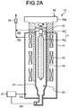
- the dehydration heating furnace 10 illustrated in FIG. 2A is a heating furnace for giving a dehydration treatment to a soot 1.
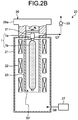
- the vitrification heating furnace 20 illustrated in FIG. 2B is a heating furnace for giving a vitrification treatment to the soot 1 that has been given the dehydration treatment to obtain an optical fiber preform that is a glass body.
- the dehydration heating furnace 10 and the vitrification heating furnace 20 constitute a soot heating mechanism for heating the soot 1.
- the soot 1 includes a glass rod 1a and a porous portion 1b formed around the outer periphery of the glass rod 1a.
- the glass rod 1a dummy rods made of silica glass are connected to opposite ends of a core preform of silica-based glass including a core portion and a cladding portion formed around the outer periphery of the core portion.
- the porous portion 1b is integrated with the cladding portion of the core preform after the vitrification treatment to form a cladding portion of the optical fiber preform.
- the glass rod 1a is obtained by connecting the glass rods to the core preform vitrified after being fabricated by, for example, a vapor-phase axial deposition (VAD) method, and the porous portion 1b is formed around the outer periphery of the glass rod 1a by an OVD method.
- VAD vapor-phase axial deposition
- the dehydration heating furnace 10 includes at least a furnace body 11, heaters 12 serving as a first heater, a muffle tube 13, a furnace core tube 14, and a discharge pump 15.
- the dehydration heating furnace 10 heats the soot 1 at a first treatment temperature lower than the softening point of the porous portion 1b to dehydrate the soot 1.
- the furnace body 11 accommodates the heaters 12, the muffle tube 13, the furnace core tube 14, and an unillustrated heat insulating member, and is made of, for example, a metal such as stainless steel.
- the heaters 12 are arranged at a plurality of positions along the longitudinal direction of the furnace core tube 14 so as to surround the outer periphery of the furnace core tube 14, and are made of, for example, a carbon material such as graphite.
- the muffle tube 13 is arranged so as to surround the furnace core tube 14 between the heaters 12 and the furnace core tube 14.
- the heat insulating member is arranged as appropriate so as to surround the outer peripheries of the heaters 12, the muffle tube 13, and the furnace core tube 14, and is made of, for example, a carbon material such as graphite.
- the furnace core tube 14 is made of silica glass and is configured to be able to accommodate the soot 1 in an internal space S1.
- a gas supply unit 17 serving as a first gas supply unit supplies a gas G3 that is an inert gas (e.g., nitrogen gas) to an area outside the furnace core tube 14 within the furnace body 11.
- the gas supply unit 17 also supplies a gas G4 that is a mixed gas of an inert gas (e.g., nitrogen gas) and a dehydration gas (e.g., chlorine gas, fluorine, and thionyl chloride (SOCl 2 )) into the furnace core tube 14.
- a gas G3 that is an inert gas (e.g., nitrogen gas)
- a dehydration gas e.g., chlorine gas, fluorine, and thionyl chloride (SOCl 2 )
- the discharge pump 15 serving as a first gas discharge unit discharges a gas outside the furnace core tube 14 within the furnace body 11 and a gas inside the furnace core tube 14 as a gas G5 and a gas G6, respectively, to an exhaust gas treatment apparatus such as a scrubber.
- connection unit 16 configured to be connectable to the connection unit 32 of the conveyance chamber 30 is also disposed in an upper portion of the dehydration heating furnace 10.
- the connection unit 16 includes a flange 16a connectable to the flange 32a of the connection unit 32.
- the connection unit 16 further includes a shut-off mechanism (not illustrated) such as a shutoff valve capable of making the insides of the furnace body 11 and the furnace core tube 14 of the dehydration heating furnace 10 airtight against the atmosphere.
- the connection unit 16 is connectable to the connection unit 32 of the conveyance chamber 30 while keeping airtightness with respect to the atmosphere. Note that a sealing mechanism may be provided in order to surely achieve the airtightness with respect to the atmosphere.
- connection unit 16 Connecting and fastening the connection unit 16 and the connection unit 32 together by use of the flanges 16a and 32a and opening the respective shut-off mechanisms enable the soot 1 and the operating mechanism 31 to move between the conveyance chamber 30 and the dehydration heating furnace 10 through the shut-off mechanisms.
- the connection unit 16 is configured to be able to hold the operating mechanism 31 moving from the conveyance chamber 30.
- the operating mechanism 31 operates the soot 1 so as to rotate around the center axis of the glass rod 1a of the soot 1 by grasping one end of the glass rod 1a in the dehydration heating furnace 10.
- a mechanism for rotating the operating mechanism 31 may be disposed inside the dehydration heating furnace 10, or outside the dehydration heating furnace 10 as long as the insides of the furnace body 11 and the furnace core tube 14 can be made airtight against the atmosphere.
- the vitrification heating furnace 20 includes at least a furnace body 21, heaters 22 serving as a second heater, a muffle tube 23, and a discharge pump 25 such as an evacuation pump.
- the vitrification heating furnace 20 heats the soot 1 at a second treatment temperature equal to or higher than the softening point of the porous portion 1b to transparently vitrify the porous portion 1b.
- the furnace body 21 accommodates the heaters 22, the muffle tube 23, and a heat insulating member (not illustrated), and is made of, for example, a metal such as stainless steel.
- the heaters 22 are made of, for example, a carbon material such as graphite.
- the muffle tube 23 serving as a structural body is arranged on the inner peripheral side of the heaters 22 so as to accommodate the soot 1 in an internal space S2.
- the heat insulating member is arranged as appropriate so as to surround the outer peripheries of the heaters 22 and the muffle tube 23.
- the muffle tube 23 and the heat insulating member are made of a material having heat resisting properties at the second treatment temperature, and are made of, for example, a carbon material such as graphite.
- having heat resisting properties at the second treatment temperature means that the muffle tube 23 and the heating insulating member maintain such mechanical properties as not to be deformed at the second treatment temperature.
- the discharge pump 25 serving as a second gas discharge unit discharges a gas inside the furnace body 21 as a gas G7 to an exhaust gas treatment apparatus such as a scrubber.
- a gas supply unit 27 serving as a second gas supply unit also introduces a gas G8 for, for example, returning an internal pressure to a predetermined pressure into the furnace body 21.
- connection unit 26 configured to be connectable to the connection unit 32 of the conveyance chamber 30 is also disposed in an upper portion of the vitrification heating furnace 20.
- the connection unit 26 includes a flange 26a connectable to the flange 32a of the connection unit 32.
- the connection unit 26 further includes a shut-off mechanism (not illustrated) such as a shutoff valve capable of making the inside of the furnace body 21 of the vitrification heating furnace 20 airtight against the atmosphere.
- the connection unit 26 is connectable to the connection unit 32 of the conveyance chamber 30 while keeping airtightness with respect to the atmosphere. Note that a sealing mechanism may be provided in order to surely achieve the airtightness with respect to the atmosphere.
- connection unit 26 Connecting and fastening the connection unit 26 and the connection unit 32 together by use of the flanges 26a and 32a and opening the respective shut-off mechanisms enable the soot 1 and the operating mechanism 31 to move between the conveyance chamber 30 and the vitrification heating furnace 20 through the shut-off mechanisms.
- the connection unit 26 is configured to be able to hold the operating mechanism 31 moving from the conveyance chamber 30.
- the operating mechanism 31 operates the soot 1 so as to rotate around the center axis of the glass rod 1a of the soot 1 by grasping one end of the glass rod 1a in the vitrification heating furnace 20.
- a mechanism for rotating the operating mechanism 31 may be disposed inside the vitrification heating furnace 20, or outside the vitrification heating furnace 20 as long as the inside of the furnace body 21 can be made airtight against the atmosphere.
- the storage 40 slowly cools and stores the optical fiber preform produced by dehydrating and vitrifying the soot 1. Note that the storage 40 may be configured as a second vitrification heating furnace.
- the fabricated soot 1 is mounted on a truck 50 that is a transport apparatus.
- the truck 50 travels on a floor F to transport the soot 1 to a rotating mechanism 60 positioned near the manufacturing apparatus 100.
- the soot 1 is transported in a state held by a holder 70 in order to prevent damage or the like.
- the conveyance chamber 30 is positioned at the position P1.
- the rotating mechanism 60 rotates the soot 1 held by the holder 70 into an erected position such that opposite ends of the glass rod 1a are arranged on the top and bottom.
- the shut-off mechanism of the connection unit 32 is then opened, and the operating mechanism 31 of the conveyance chamber 30 grasps one end of the glass rod 1a of the soot 1 to lift the soot 1.
- the soot 1 is thereby accommodated and held in the conveyance chamber 30.
- the shut-off mechanism of the connection unit 32 is closed after accommodating the soot 1, making the inside of the conveyance chamber 30 airtight.
- the gas G1 (e.g., inert gas) is then supplied into the conveyance chamber 30 to obtain a predetermined atmosphere with the discharge pump 33 discharging the atmosphere inside the conveyance chamber 30.
- the inside of the furnace core tube 14 of the dehydration heating furnace 10 is also brought into an inert gas atmosphere.
- a dry atmosphere is preferably employed.
- the dry atmosphere is an atmosphere containing a sufficiently small amount of moisture or no moisture.
- the insides of the conveyance chamber 30 and the furnace core tube 14 may be depressurized.
- connection unit 32 of the conveyance chamber 30 and the connection unit 16 of the dehydration heating furnace 10 are connected together by the flanges 16a and 32a and the sealing mechanism while keeping the airtightness with respect to the atmosphere.
- a flange member may be interposed as a joint between the connection unit 32 and the connection unit 16, and a discharge pump or a gas introduction mechanism connected to the flanges may depressurize the inside of the flange member or replace the inside of the flange member with an inert gas.
- the respective shut-off mechanisms of the connection unit 32 and the connection unit 16 are opened, bringing the insides of the conveyance chamber 30 and the furnace core tube 14 of the dehydration heating furnace 10 into communication with each other while keeping the airtightness with respect to the atmosphere.
- the operating mechanism 31 lowers the soot 1 to guide the soot 1 into the dehydration heating furnace 10.
- the operating mechanism 31 also enters the dehydration heating furnace 10 to be held by the connection unit 16.
- the respective shut-off mechanisms of the connection unit 32 and the connection unit 16 are closed.
- the conveyance chamber 30 and the dehydration heating furnace 10 are then disconnected from each other.
- the soot 1 is guided into the dehydration heating furnace 10 from the conveyance chamber 30 without being exposed to the atmosphere as described above.
- the dehydration heating furnace 10 heats the soot 1 that is rotated by the operating mechanism 31 at the first treatment temperature for a predetermined length of time by the heaters 12 to dehydrate the soot 1.
- the gas G3 and the gas G4 are supplied.
- the first temperature is, for example, a temperature between 1100°C and 1250°C.
- the pressure of the gas G4 in the furnace core tube 14 is set to, for example, atmospheric pressure, the gas G4 may be also in a depressurized state or in a pressurized state slightly higher than the atmospheric pressure. Note that the dehydration treatment may be performed in two stages.
- the soot 1 may be first heated at 1100°C for a predetermined length of time as a first dehydration treatment, and then heated at 1250°C for a predetermined length of time as a second dehydration treatment.
- the conveyance chamber 30 moves to, for example, the position P4 to be set to a standby state during the dehydration treatment.
- the conveyance chamber 30 moves to the position P2, and the connection unit 32 of the conveyance chamber 30 and the connection unit 16 of the dehydration heating furnace 10 are connected together while keeping the airtightness with respect to the atmosphere as illustrated in FIG. 7 .
- the respective shut-off mechanisms of the connection unit 32 and the connection unit 16 are then opened, bringing the insides of the conveyance chamber 30 and the furnace core tube 14 of the dehydration heating furnace 10 into communication with each other while keeping the airtightness with respect to the atmosphere.
- the operating mechanism 31 grasping the dehydrated soot 1 moves to lift within the conveyance chamber 30, guiding the soot 1 into the conveyance chamber 30.
- the respective shut-off mechanisms of the connection unit 32 and the connection unit 16 are closed.
- the conveyance chamber 30 and the dehydration heating furnace 10 are then disconnected from each other. Note that the inside of the conveyance chamber 30 is set to atmospheric pressure under the inert gas dry atmosphere or is depressurized before accommodating the dehydrated soot 1.
- the dehydration gas contained in the gas G4 inside the furnace core tube 14 of the dehydration heating furnace 10 is prevented from being exposed to the atmosphere.
- the dehydration gas is prevented from reacting with moisture in the atmosphere to generate a corrosive substance.
- the dehydration gas is chlorine gas
- hydrochloric acid is generated as the corrosive substance. Consequently, the dehydration heating furnace 10, the vitrification heating furnace 20, and other facilities of the manufacturing apparatus 100 are not damaged by the corrosive substance, thereby preventing a decrease in operation rate of the manufacturing apparatus 100 and an increase in maintenance cost thereof.
- connection unit 32 of the conveyance chamber 30 and the connection unit 26 of the vitrification heating furnace 20 are connected together by the flanges 26a and 32a and the sealing mechanism while keeping the airtightness with respect to the atmosphere.
- a flange member may be interposed as a joint between the connection unit 32 and the connection unit 26, and a discharge pump or a gas introduction mechanism connected to the flanges may depressurize the inside of the flange member or replace the inside of the flange member with an inert gas.
- the respective shut-off mechanisms of the connection unit 32 and the connection unit 26 are opened, bringing the inside of the conveyance chamber 30 and the internal space S2 of the vitrification heating furnace 20 into communication with each other while keeping the airtightness with respect to the atmosphere.
- the operating mechanism 31 lowers the soot 1 to guide the soot 1 into the vitrification heating furnace 20.
- the operating mechanism 31 also enters the vitrification heating furnace 20 to be held by the connection unit 26. After the soot 1 is guided and accommodated in the internal space S2 and the operating mechanism 31 is held by the connection unit 26, the respective shut-off mechanisms of the connection unit 32 and the connection unit 26 are closed.
- the conveyance chamber 30 and the vitrification heating furnace 20 are then disconnected from each other.
- the soot 1 is guided into the vitrification heating furnace 20 from the conveyance chamber 30 without being exposed to the atmosphere as described above.
- the conveyance chamber 30 and the moving mechanism constitute a soot conveying mechanism for conveying the soot 1 between the dehydration heating furnace 10 and the vitrification heating furnace 20 as described above.
- the vitrification heating furnace 20 heats the soot 1 that is rotated by the operating mechanism 31 at the second treatment temperature for a predetermined length of time by the heaters 22 to transparently vitrify the porous portion 1b.
- the second temperature is, for example, 1400°C.
- the inside of the vitrification heating furnace 20 is depressurized to, for example, a pressure lower than the atmospheric pressure.
- the transparent vitrification treatment may be performed by supplying an inert gas into the vitrification heating furnace 20 and heating the soot 1 under the atmospheric pressure in the vitrification treatment.
- the conveyance chamber 30 moves to, for example, the position P4 to be set to a standby state during the vitrification treatment.
- the conveyance chamber 30 moves to the position P3, and the connection unit 32 of the conveyance chamber 30 and the connection unit 26 of the vitrification heating furnace 20 are connected together while keeping the airtightness with respect to the atmosphere as illustrated in FIG. 9 .
- the respective shut-off mechanisms of the connection unit 32 and the connection unit 26 are then opened, bringing the inside of the conveyance chamber 30 and the internal space S2 of the vitrification heating furnace 20 into communication with each other while keeping the airtightness with respect to the atmosphere.
- the operating mechanism 31 grasping an optical fiber preform 2 obtained after the vitrification treatment moves to lift within the conveyance chamber 30, thereby guiding the optical fiber preform 2 into the conveyance chamber 30.
- the optical fiber preform 2 includes the glass rod 1a and a glass portion 2b formed around the outer periphery of the glass rod 1a.
- the glass portion 2b is obtained by transparently vitrifying the porous portion 1b.
- the soot 1 or the optical fiber preform 2 is moved between the conveyance chamber 30 and the dehydration heating furnace 10 or the vitrification heating furnace 20, the soot 1 or the optical fiber preform 2 is always moved under the inert atmosphere or in the depressurized state, and thus not exposed to the atmosphere.
- the vitrification heating furnace 20 includes no furnace core tube made of silica therein, and the muffle tube 23 has heat resisting properties at the second treatment temperature, thus preventing occurrence of deformation and devitrification problems that could occur when the vitrification heating furnace 20 includes a furnace core tube made of silica. As a result, the decrease in the operation rate of the manufacturing apparatus 100 and the increase in the maintenance cost thereof can be prevented.
- the furnace core tube made of silica needs to have a larger size so as to accommodate the soot.
- the size increase markedly increases the cost.
- the vitrification heating furnace 20, which includes no furnace core tube made of silica therein, can prevent the cost increase caused when the size of the vitrification heating furnace 20 is increased.
- the inside of the vitrification heating furnace 20 can be kept airtight against the atmosphere when the soot 1 is guided into the vitrification heating furnace 20 and the optical fiber preform 2 is guided out of the vitrification heating furnace 20, thus preventing the atmosphere from being introduced to corrode and deteriorate the heaters 22, the muffle tube 23, and the heat insulating member. As a result, the decrease in the operation rate of the manufacturing apparatus 100 and the increase in the maintenance cost thereof can be prevented.
- the conveyance chamber 30 moves to the position P4, and the operating mechanism 31 lowers the optical fiber preform 2 to guide the optical fiber preform 2 into the storage 40.
- the structural body in the vitrification heating furnace which is the muffle tube made of a carbon material in the above embodiment, may be a structural body made of any desired material, such as a ceramic material, that has heat resisting properties at the second treatment temperature.
- the structural body may be also a furnace core tube.
- the furnace core tube is positioned in the furnace body similarly to the furnace core tube in the dehydration heating furnace, and the muffle tube is separately positioned between the furnace core tube and the heaters.
- the heat insulating member is also positioned in the furnace body similarly to the heat insulating member in the dehydration heating furnace.
- optical fiber preform is manufactured as the glass body in the above embodiment, any desired glass body other than the optical fiber preform may be manufactured.
- the above embodiment does not limit the present invention.
- the present invention encompasses a configuration obtained by combining the respective constituent elements described above as appropriate.
- a person skilled in the art can also easily conceive additional effects and modifications.
- a broader aspect of the present invention is not limited to the above embodiment, and various modifications may be made.
- the glass body manufacturing apparatus As described above, the glass body manufacturing apparatus, the glass body manufacturing method, the soot conveying mechanism, and the soot heating mechanism according to the present invention are useful for manufacturing the optical fiber preform.
- Reference Signs List As described above, the glass body manufacturing apparatus, the glass body manufacturing method, the soot conveying mechanism, and the soot heating mechanism according to the present invention are useful for manufacturing the optical fiber preform.
Landscapes
- Engineering & Computer Science (AREA)
- Chemical & Material Sciences (AREA)
- Geochemistry & Mineralogy (AREA)
- Manufacturing & Machinery (AREA)
- Chemical Kinetics & Catalysis (AREA)
- General Chemical & Material Sciences (AREA)
- Life Sciences & Earth Sciences (AREA)
- General Life Sciences & Earth Sciences (AREA)
- Organic Chemistry (AREA)
- Materials Engineering (AREA)
- General Engineering & Computer Science (AREA)
- Mechanical Engineering (AREA)
- Physics & Mathematics (AREA)
- Thermal Sciences (AREA)
- Manufacture, Treatment Of Glass Fibers (AREA)
- Glass Melting And Manufacturing (AREA)
Abstract
Description
- The present invention relates to a glass body manufacturing apparatus, a glass body manufacturing method, a soot conveying mechanism, and a soot heating mechanism.
- Silica glass optical fibers are typically manufactured by drawing an optical fiber preform that is a glass body made of silica-based glass. To manufacture the optical fiber preform, for example, an outside vapor-phase deposition (OVD) method is used. When the OVD method is used, a soot is fabricated by depositing silica glass particles around the outer periphery of a target rod made of silica-based glass to form a porous portion in layers. The soot is then given a so-called dehydration treatment in which the soot is heated under a dehydration gas atmosphere in order to remove a hydroxyl group contained in the porous portion. The dehydration treatment is performed at a temperature lower than the softening point of the silica glass forming the soot. Subsequently, the soot is given a vitrification treatment in which the soot is heated at a temperature equal to or higher than the softening point. This removes holes existing within the porous portion, thereby converting the porous portion into transparent glass (appropriately referred to as transparent vitrification below).
- The dehydration treatment and the vitrification treatment are performed in the same heating furnace or different heating furnaces. Additionally, the heating furnace typically includes a furnace core tube made of silica glass (e.g.,
Patent Literatures 1 and 2). -
- Patent Literature 1: Japanese Laid-open Patent Publication No.
2004-345869 - Patent Literature 2: Japanese Laid-open Patent Publication No.
2007-153708 - However, since the vitrification treatment is performed at a temperature equal to or higher than the softening point, the furnace core tube made of silica glass may soften to be deformed or devitrified. It is necessary to perform maintenance by, for example, replacing the furnace core tube if the furnace core tube is deformed or devitrified, resulting in a decrease in operation rate of the heating furnace and an entire glass body manufacturing apparatus including the heating furnace, and an increase in maintenance cost thereof.
- Meanwhile, the dehydration treatment and the vitrification treatment can be performed in different heating furnaces. In this case, for example, a method of performing the vitrification treatment in a heating furnace including a furnace core tube having heat resisting properties at the vitrification treatment temperature can be employed. However, this method may cause the atmosphere to flow into a dehydration heating furnace for performing the dehydration treatment when the soot is transferred from the dehydration heating furnace to a vitrification heating furnace for performing the vitrification treatment. If the atmosphere flows into the dehydration heating furnace, moisture in the atmosphere and a dehydration gas may react with each other to generate a corrosive substance, which may damage the dehydration heating furnace. Additionally, the corrosive substance may adhere to the soot to be conveyed to the vitrification heating furnace together with the soot. Moreover, the corrosive substance generated in the dehydration heating furnace may leak to the outside, or the dehydration gas may leak and react with moisture in the atmosphere to generate a corrosive substance outside the dehydration heating furnace, thus damaging the dehydration heating furnace and other facilities.
- The present invention has been made in view of the above problems, and it is an object thereof to provide a glass body manufacturing apparatus, a glass body manufacturing method, a soot conveying mechanism, and a soot heating mechanism capable of preventing a decrease in operation rate and an increase in maintenance cost. Solution to Problem
- To resolve the above problem and attain the object, a glass body manufacturing apparatus according to an embodiment of the present invention for manufacturing a glass body by dehydrating and transparently vitrifying a soot having a porous portion, the glass body manufacturing apparatus includes: a first heating furnace including a furnace core tube accommodating the soot and a first heater, the first heating furnace supplying a dehydration gas into the furnace core tube and heating the soot at a first treatment temperature, which is lower than a softening point of the porous portion, by the first heater; a second heating furnace including a structural body configured to accommodate the soot and a second heater, the second heating furnace heating the soot at a second treatment temperature, which is equal to or higher than the softening point, by the second heater; and a conveyance container connectable to each of the first heating furnace and the second heating furnace while keeping airtightness with respect to the atmosphere, the conveyance container being configured to accommodate and hold the soot, and convey the soot between the first heating furnace and the second heating furnace.
- According to an embodiment of the present invention, in the glass body manufacturing apparatus, the structural body is positioned in a furnace body, and is made of a carbon material or a ceramic material.
- According to an embodiment of the present invention, in the glass body manufacturing apparatus, the structural body is a furnace core tube.
- A glass body manufacturing method according to an embodiment of the present invention, includes: in a first heating furnace, accommodating a soot having a porous portion in a furnace core tube made of glass, supplying a dehydration gas into the furnace core tube, and heating the soot at a first treatment temperature, which is lower than a softening point of the porous portion; connecting a conveyance container and the first heating furnace together while keeping airtightness with respect to the atmosphere, accommodating and holding the soot in the conveyance container, and conveying the soot to a second heating furnace; and connecting the conveyance container and the second heating furnace together while keeping airtightness with respect to the atmosphere, accommodating the soot in a structural body, and heating the soot at a second treatment temperature.
- A soot conveying mechanism according to an embodiment of the present invention to convey a soot between a first heating furnace and a second heating furnace, includes: a conveyance container accommodating the soot; and a moving mechanism moving the conveyance container to a position above the first heating furnace and a position above the second heating furnace. Further, the conveyance container includes: an operating mechanism capable of lifting and lowering the soot within the conveyance container, an airtight mechanism capable of making inside the conveyance container airtight, and a connection unit configured to be connectable to the first heating furnace or the second heating furnace.
- According to an embodiment of the present invention, the soot conveying mechanism further includes a rotating mechanism erecting the soot such that opposite ends of a glass rod in the soot are positioned in top and bottom.
- A soot heating mechanism according to an embodiment of the present invention to convert a soot into a fiber preform, includes: a first heating furnace including a furnace core tube accommodating the soot, a first heater, a first gas supply unit supplying a dehydration gas into the furnace core tube, and a first gas discharge unit discharging the dehydration gas, the first heating furnace heating the soot at a first treatment temperature by the first heater under an atmosphere of the dehydration gas; and a second heating furnace including a structural body configured to accommodate the soot, a second heater, a second gas supply unit supplying an inert gas into the structural body, and a second gas discharge unit discharging the inert gas, the second heating furnace heating the soot at a second treatment temperature by the second heater under an atmosphere of the inert gas. Advantageous Effects of Invention
- The present invention can achieve the glass body manufacturing apparatus, the glass body manufacturing method, the soot conveying mechanism, and the soot heating mechanism capable of preventing a decrease in operation rate and an increase in maintenance cost.
-
-
FIG. 1 is a schematic view illustrating a configuration of a glass body manufacturing apparatus according to an embodiment. -
FIG. 2A is a schematic view illustrating a configuration of a dehydration heating furnace. -
FIG. 2B is a schematic view illustrating a configuration of a vitrification heating furnace. -
FIG. 3 is a schematic view illustrating a glass body manufacturing method. -
FIG. 4 is a schematic view illustrating the glass body manufacturing method. -
FIG. 5 is a schematic view illustrating the glass body manufacturing method. -
FIG. 6 is a schematic view illustrating the glass body manufacturing method. -
FIG. 7 is a schematic view illustrating the glass body manufacturing method. -
FIG. 8 is a schematic view illustrating the glass body manufacturing method. -
FIG. 9 is a schematic view illustrating the glass body manufacturing method. -
FIG. 10 is a schematic view illustrating the glass body manufacturing method. - In the following, an embodiment of the present invention will be described with reference to the accompanied drawings. Note that the embodiment does not limit the invention. Additionally, in description of the drawings, the same or corresponding elements are denoted by the same reference numerals as appropriate.
-
FIG. 1 is a schematic view illustrating a configuration of a glass body manufacturing apparatus according to the embodiment. Amanufacturing apparatus 100 includes at least adehydration heating furnace 10 serving as a first heating furnace, avitrification heating furnace 20 serving as a second heating furnace, aconveyance chamber 30 serving as a conveyance container, and astorage 40. - First, the
conveyance chamber 30 will be described. Theconveyance chamber 30 is made of, for example, a metal such as stainless steel, and includes anoperating mechanism 31, aconnection unit 32, and adischarge pump 33. Theconveyance chamber 30 is also configured to be freely movable to a position P1, a position P2 above thedehydration heating furnace 10, a position P3 above thevitrification heating furnace 20, and a position P4 above thestorage 40 by an unillustrated moving mechanism. - The
operating mechanism 31 is configured to be liftable and lowerable within theconveyance chamber 30. Theoperating mechanism 31 will be described in detail later. - The
connection unit 32 is disposed at one end of theconveyance chamber 30, and includes aflange 32a. Theconnection unit 32 also includes a shut-off mechanism such as a shutoff valve constituting an airtight mechanism capable of making the inside of theconveyance chamber 30 airtight. - Additionally, a gas supply unit supplies a gas G1 that is an inert gas (e.g., nitrogen gas) into the
conveyance chamber 30. Thedischarge pump 33 also discharges a gas inside theconveyance chamber 30 as a gas G2 to an exhaust gas treatment apparatus such as a scrubber. - Next, the configuration of the
dehydration heating furnace 10 and the configuration of thevitrification heating furnace 20 will be described with reference toFIGS. 2A and2B , respectively. Thedehydration heating furnace 10 illustrated inFIG. 2A is a heating furnace for giving a dehydration treatment to asoot 1. Thevitrification heating furnace 20 illustrated inFIG. 2B is a heating furnace for giving a vitrification treatment to thesoot 1 that has been given the dehydration treatment to obtain an optical fiber preform that is a glass body. Thedehydration heating furnace 10 and thevitrification heating furnace 20 constitute a soot heating mechanism for heating thesoot 1. Thesoot 1 includes aglass rod 1a and aporous portion 1b formed around the outer periphery of theglass rod 1a. For theglass rod 1a, dummy rods made of silica glass are connected to opposite ends of a core preform of silica-based glass including a core portion and a cladding portion formed around the outer periphery of the core portion. Theporous portion 1b is integrated with the cladding portion of the core preform after the vitrification treatment to form a cladding portion of the optical fiber preform. For thesoot 1, theglass rod 1a is obtained by connecting the glass rods to the core preform vitrified after being fabricated by, for example, a vapor-phase axial deposition (VAD) method, and theporous portion 1b is formed around the outer periphery of theglass rod 1a by an OVD method. - As illustrated in
FIG. 2A , thedehydration heating furnace 10 includes at least afurnace body 11,heaters 12 serving as a first heater, amuffle tube 13, afurnace core tube 14, and adischarge pump 15. Thedehydration heating furnace 10 heats thesoot 1 at a first treatment temperature lower than the softening point of theporous portion 1b to dehydrate thesoot 1. - The
furnace body 11 accommodates theheaters 12, themuffle tube 13, thefurnace core tube 14, and an unillustrated heat insulating member, and is made of, for example, a metal such as stainless steel. Theheaters 12 are arranged at a plurality of positions along the longitudinal direction of thefurnace core tube 14 so as to surround the outer periphery of thefurnace core tube 14, and are made of, for example, a carbon material such as graphite. Themuffle tube 13 is arranged so as to surround thefurnace core tube 14 between theheaters 12 and thefurnace core tube 14. The heat insulating member is arranged as appropriate so as to surround the outer peripheries of theheaters 12, themuffle tube 13, and thefurnace core tube 14, and is made of, for example, a carbon material such as graphite. Thefurnace core tube 14 is made of silica glass and is configured to be able to accommodate thesoot 1 in an internal space S1. - In the dehydration treatment, a
gas supply unit 17 serving as a first gas supply unit supplies a gas G3 that is an inert gas (e.g., nitrogen gas) to an area outside thefurnace core tube 14 within thefurnace body 11. Thegas supply unit 17 also supplies a gas G4 that is a mixed gas of an inert gas (e.g., nitrogen gas) and a dehydration gas (e.g., chlorine gas, fluorine, and thionyl chloride (SOCl2)) into thefurnace core tube 14. Thedischarge pump 15 serving as a first gas discharge unit discharges a gas outside thefurnace core tube 14 within thefurnace body 11 and a gas inside thefurnace core tube 14 as a gas G5 and a gas G6, respectively, to an exhaust gas treatment apparatus such as a scrubber. - A
connection unit 16 configured to be connectable to theconnection unit 32 of theconveyance chamber 30 is also disposed in an upper portion of thedehydration heating furnace 10. Theconnection unit 16 includes aflange 16a connectable to theflange 32a of theconnection unit 32. Theconnection unit 16 further includes a shut-off mechanism (not illustrated) such as a shutoff valve capable of making the insides of thefurnace body 11 and thefurnace core tube 14 of thedehydration heating furnace 10 airtight against the atmosphere. Theconnection unit 16 is connectable to theconnection unit 32 of theconveyance chamber 30 while keeping airtightness with respect to the atmosphere. Note that a sealing mechanism may be provided in order to surely achieve the airtightness with respect to the atmosphere. Connecting and fastening theconnection unit 16 and theconnection unit 32 together by use of theflanges soot 1 and theoperating mechanism 31 to move between theconveyance chamber 30 and thedehydration heating furnace 10 through the shut-off mechanisms. Theconnection unit 16 is configured to be able to hold theoperating mechanism 31 moving from theconveyance chamber 30. Theoperating mechanism 31 operates thesoot 1 so as to rotate around the center axis of theglass rod 1a of thesoot 1 by grasping one end of theglass rod 1a in thedehydration heating furnace 10. Note that a mechanism for rotating theoperating mechanism 31 may be disposed inside thedehydration heating furnace 10, or outside thedehydration heating furnace 10 as long as the insides of thefurnace body 11 and thefurnace core tube 14 can be made airtight against the atmosphere. - As illustrated in
FIG. 2B , thevitrification heating furnace 20 includes at least afurnace body 21,heaters 22 serving as a second heater, amuffle tube 23, and adischarge pump 25 such as an evacuation pump. Thevitrification heating furnace 20 heats thesoot 1 at a second treatment temperature equal to or higher than the softening point of theporous portion 1b to transparently vitrify theporous portion 1b. - The
furnace body 21 accommodates theheaters 22, themuffle tube 23, and a heat insulating member (not illustrated), and is made of, for example, a metal such as stainless steel. Theheaters 22 are made of, for example, a carbon material such as graphite. Themuffle tube 23 serving as a structural body is arranged on the inner peripheral side of theheaters 22 so as to accommodate thesoot 1 in an internal space S2. The heat insulating member is arranged as appropriate so as to surround the outer peripheries of theheaters 22 and themuffle tube 23. Themuffle tube 23 and the heat insulating member are made of a material having heat resisting properties at the second treatment temperature, and are made of, for example, a carbon material such as graphite. Here, having heat resisting properties at the second treatment temperature means that themuffle tube 23 and the heating insulating member maintain such mechanical properties as not to be deformed at the second treatment temperature. - In the vitrification treatment, the
discharge pump 25 serving as a second gas discharge unit discharges a gas inside thefurnace body 21 as a gas G7 to an exhaust gas treatment apparatus such as a scrubber. Agas supply unit 27 serving as a second gas supply unit also introduces a gas G8 for, for example, returning an internal pressure to a predetermined pressure into thefurnace body 21. - A
connection unit 26 configured to be connectable to theconnection unit 32 of theconveyance chamber 30 is also disposed in an upper portion of thevitrification heating furnace 20. Theconnection unit 26 includes aflange 26a connectable to theflange 32a of theconnection unit 32. Theconnection unit 26 further includes a shut-off mechanism (not illustrated) such as a shutoff valve capable of making the inside of thefurnace body 21 of thevitrification heating furnace 20 airtight against the atmosphere. Theconnection unit 26 is connectable to theconnection unit 32 of theconveyance chamber 30 while keeping airtightness with respect to the atmosphere. Note that a sealing mechanism may be provided in order to surely achieve the airtightness with respect to the atmosphere. Connecting and fastening theconnection unit 26 and theconnection unit 32 together by use of theflanges soot 1 and theoperating mechanism 31 to move between theconveyance chamber 30 and thevitrification heating furnace 20 through the shut-off mechanisms. Theconnection unit 26 is configured to be able to hold theoperating mechanism 31 moving from theconveyance chamber 30. Theoperating mechanism 31 operates thesoot 1 so as to rotate around the center axis of theglass rod 1a of thesoot 1 by grasping one end of theglass rod 1a in thevitrification heating furnace 20. Note that a mechanism for rotating theoperating mechanism 31 may be disposed inside thevitrification heating furnace 20, or outside thevitrification heating furnace 20 as long as the inside of thefurnace body 21 can be made airtight against the atmosphere. - The
storage 40 slowly cools and stores the optical fiber preform produced by dehydrating and vitrifying thesoot 1. Note that thestorage 40 may be configured as a second vitrification heating furnace. - Next, a method for manufacturing an optical fiber preform by using the
manufacturing apparatus 100 will be described with reference toFIGS. 3 to 10 . First, as illustrated inFIG. 3 , the fabricatedsoot 1 is mounted on atruck 50 that is a transport apparatus. Thetruck 50 travels on a floor F to transport thesoot 1 to arotating mechanism 60 positioned near themanufacturing apparatus 100. Here, thesoot 1 is transported in a state held by aholder 70 in order to prevent damage or the like. Also, theconveyance chamber 30 is positioned at the position P1. - Subsequently, as illustrated in
FIG. 4 , the rotatingmechanism 60 rotates thesoot 1 held by theholder 70 into an erected position such that opposite ends of theglass rod 1a are arranged on the top and bottom. The shut-off mechanism of theconnection unit 32 is then opened, and theoperating mechanism 31 of theconveyance chamber 30 grasps one end of theglass rod 1a of thesoot 1 to lift thesoot 1. Thesoot 1 is thereby accommodated and held in theconveyance chamber 30. The shut-off mechanism of theconnection unit 32 is closed after accommodating thesoot 1, making the inside of theconveyance chamber 30 airtight. The gas G1 (e.g., inert gas) is then supplied into theconveyance chamber 30 to obtain a predetermined atmosphere with thedischarge pump 33 discharging the atmosphere inside theconveyance chamber 30. Meanwhile, the inside of thefurnace core tube 14 of thedehydration heating furnace 10 is also brought into an inert gas atmosphere. Here, a dry atmosphere is preferably employed. The dry atmosphere is an atmosphere containing a sufficiently small amount of moisture or no moisture. Alternatively, the insides of theconveyance chamber 30 and thefurnace core tube 14 may be depressurized. - Subsequently, as illustrated in
FIG. 5 , theconveyance chamber 30 moves from the position P1 to the position P2. Theconnection unit 32 of theconveyance chamber 30 and theconnection unit 16 of thedehydration heating furnace 10 are connected together by theflanges connection unit 32 and theconnection unit 16, and a discharge pump or a gas introduction mechanism connected to the flanges may depressurize the inside of the flange member or replace the inside of the flange member with an inert gas. After that, the respective shut-off mechanisms of theconnection unit 32 and theconnection unit 16 are opened, bringing the insides of theconveyance chamber 30 and thefurnace core tube 14 of thedehydration heating furnace 10 into communication with each other while keeping the airtightness with respect to the atmosphere. Subsequently, theoperating mechanism 31 lowers thesoot 1 to guide thesoot 1 into thedehydration heating furnace 10. Theoperating mechanism 31 also enters thedehydration heating furnace 10 to be held by theconnection unit 16. After thesoot 1 is guided and accommodated in thefurnace core tube 14 and theoperating mechanism 31 is held by theconnection unit 16, the respective shut-off mechanisms of theconnection unit 32 and theconnection unit 16 are closed. Theconveyance chamber 30 and thedehydration heating furnace 10 are then disconnected from each other. Thesoot 1 is guided into thedehydration heating furnace 10 from theconveyance chamber 30 without being exposed to the atmosphere as described above. - Subsequently, as illustrated in
FIG. 6 , thedehydration heating furnace 10 heats thesoot 1 that is rotated by theoperating mechanism 31 at the first treatment temperature for a predetermined length of time by theheaters 12 to dehydrate thesoot 1. In the dehydration treatment, the gas G3 and the gas G4 are supplied. The first temperature is, for example, a temperature between 1100°C and 1250°C. Although the pressure of the gas G4 in thefurnace core tube 14 is set to, for example, atmospheric pressure, the gas G4 may be also in a depressurized state or in a pressurized state slightly higher than the atmospheric pressure. Note that the dehydration treatment may be performed in two stages. In this case, for example, thesoot 1 may be first heated at 1100°C for a predetermined length of time as a first dehydration treatment, and then heated at 1250°C for a predetermined length of time as a second dehydration treatment. Theconveyance chamber 30 moves to, for example, the position P4 to be set to a standby state during the dehydration treatment. - When the dehydration treatment is finished, the
conveyance chamber 30 moves to the position P2, and theconnection unit 32 of theconveyance chamber 30 and theconnection unit 16 of thedehydration heating furnace 10 are connected together while keeping the airtightness with respect to the atmosphere as illustrated inFIG. 7 . The respective shut-off mechanisms of theconnection unit 32 and theconnection unit 16 are then opened, bringing the insides of theconveyance chamber 30 and thefurnace core tube 14 of thedehydration heating furnace 10 into communication with each other while keeping the airtightness with respect to the atmosphere. Subsequently, theoperating mechanism 31 grasping thedehydrated soot 1 moves to lift within theconveyance chamber 30, guiding thesoot 1 into theconveyance chamber 30. After thesoot 1 is guided and accommodated in theconveyance chamber 30, the respective shut-off mechanisms of theconnection unit 32 and theconnection unit 16 are closed. Theconveyance chamber 30 and thedehydration heating furnace 10 are then disconnected from each other. Note that the inside of theconveyance chamber 30 is set to atmospheric pressure under the inert gas dry atmosphere or is depressurized before accommodating thedehydrated soot 1. - Thus, the dehydration gas contained in the gas G4 inside the
furnace core tube 14 of thedehydration heating furnace 10 is prevented from being exposed to the atmosphere. As a result, the dehydration gas is prevented from reacting with moisture in the atmosphere to generate a corrosive substance. For example, when the dehydration gas is chlorine gas, hydrochloric acid is generated as the corrosive substance. Consequently, thedehydration heating furnace 10, thevitrification heating furnace 20, and other facilities of themanufacturing apparatus 100 are not damaged by the corrosive substance, thereby preventing a decrease in operation rate of themanufacturing apparatus 100 and an increase in maintenance cost thereof. - Subsequently, as illustrated in
FIG. 8 , theconveyance chamber 30 moves to the position P3. Theconnection unit 32 of theconveyance chamber 30 and theconnection unit 26 of thevitrification heating furnace 20 are connected together by theflanges connection unit 32 and theconnection unit 26, and a discharge pump or a gas introduction mechanism connected to the flanges may depressurize the inside of the flange member or replace the inside of the flange member with an inert gas. After that, the respective shut-off mechanisms of theconnection unit 32 and theconnection unit 26 are opened, bringing the inside of theconveyance chamber 30 and the internal space S2 of thevitrification heating furnace 20 into communication with each other while keeping the airtightness with respect to the atmosphere. Subsequently, theoperating mechanism 31 lowers thesoot 1 to guide thesoot 1 into thevitrification heating furnace 20. Theoperating mechanism 31 also enters thevitrification heating furnace 20 to be held by theconnection unit 26. After thesoot 1 is guided and accommodated in the internal space S2 and theoperating mechanism 31 is held by theconnection unit 26, the respective shut-off mechanisms of theconnection unit 32 and theconnection unit 26 are closed. Theconveyance chamber 30 and thevitrification heating furnace 20 are then disconnected from each other. Thesoot 1 is guided into thevitrification heating furnace 20 from theconveyance chamber 30 without being exposed to the atmosphere as described above. Theconveyance chamber 30 and the moving mechanism constitute a soot conveying mechanism for conveying thesoot 1 between thedehydration heating furnace 10 and thevitrification heating furnace 20 as described above. - Subsequently, the
vitrification heating furnace 20 heats thesoot 1 that is rotated by theoperating mechanism 31 at the second treatment temperature for a predetermined length of time by theheaters 22 to transparently vitrify theporous portion 1b. The second temperature is, for example, 1400°C. The inside of thevitrification heating furnace 20 is depressurized to, for example, a pressure lower than the atmospheric pressure. Alternatively, the transparent vitrification treatment may be performed by supplying an inert gas into thevitrification heating furnace 20 and heating thesoot 1 under the atmospheric pressure in the vitrification treatment. Theconveyance chamber 30 moves to, for example, the position P4 to be set to a standby state during the vitrification treatment. - When the vitrification treatment is finished, the
conveyance chamber 30 moves to the position P3, and theconnection unit 32 of theconveyance chamber 30 and theconnection unit 26 of thevitrification heating furnace 20 are connected together while keeping the airtightness with respect to the atmosphere as illustrated inFIG. 9 . The respective shut-off mechanisms of theconnection unit 32 and theconnection unit 26 are then opened, bringing the inside of theconveyance chamber 30 and the internal space S2 of thevitrification heating furnace 20 into communication with each other while keeping the airtightness with respect to the atmosphere. Subsequently, theoperating mechanism 31 grasping anoptical fiber preform 2 obtained after the vitrification treatment moves to lift within theconveyance chamber 30, thereby guiding theoptical fiber preform 2 into theconveyance chamber 30. Note that theoptical fiber preform 2 includes theglass rod 1a and aglass portion 2b formed around the outer periphery of theglass rod 1a. Theglass portion 2b is obtained by transparently vitrifying theporous portion 1b. After theoptical fiber preform 2 is guided and accommodated in theconveyance chamber 30, the respective shut-off mechanisms of theconnection unit 32 and theconnection unit 26 are closed. Theconveyance chamber 30 and thevitrification heating furnace 20 are then disconnected from each other. - That is, when the
soot 1 or theoptical fiber preform 2 is moved between theconveyance chamber 30 and thedehydration heating furnace 10 or thevitrification heating furnace 20, thesoot 1 or theoptical fiber preform 2 is always moved under the inert atmosphere or in the depressurized state, and thus not exposed to the atmosphere. - Here, the
vitrification heating furnace 20 includes no furnace core tube made of silica therein, and themuffle tube 23 has heat resisting properties at the second treatment temperature, thus preventing occurrence of deformation and devitrification problems that could occur when thevitrification heating furnace 20 includes a furnace core tube made of silica. As a result, the decrease in the operation rate of themanufacturing apparatus 100 and the increase in the maintenance cost thereof can be prevented. - Additionally, as the size of the soot to be treated increases, the furnace core tube made of silica needs to have a larger size so as to accommodate the soot. The size increase markedly increases the cost. However, the
vitrification heating furnace 20, which includes no furnace core tube made of silica therein, can prevent the cost increase caused when the size of thevitrification heating furnace 20 is increased. - Moreover, the inside of the
vitrification heating furnace 20 can be kept airtight against the atmosphere when thesoot 1 is guided into thevitrification heating furnace 20 and theoptical fiber preform 2 is guided out of thevitrification heating furnace 20, thus preventing the atmosphere from being introduced to corrode and deteriorate theheaters 22, themuffle tube 23, and the heat insulating member. As a result, the decrease in the operation rate of themanufacturing apparatus 100 and the increase in the maintenance cost thereof can be prevented. - After that, as illustrated in
FIG. 10 , theconveyance chamber 30 moves to the position P4, and theoperating mechanism 31 lowers theoptical fiber preform 2 to guide theoptical fiber preform 2 into thestorage 40. - Note that the structural body in the vitrification heating furnace, which is the muffle tube made of a carbon material in the above embodiment, may be a structural body made of any desired material, such as a ceramic material, that has heat resisting properties at the second treatment temperature. The structural body may be also a furnace core tube. When the structural body is a furnace core tube, the furnace core tube is positioned in the furnace body similarly to the furnace core tube in the dehydration heating furnace, and the muffle tube is separately positioned between the furnace core tube and the heaters. The heat insulating member is also positioned in the furnace body similarly to the heat insulating member in the dehydration heating furnace.
- Additionally, although the optical fiber preform is manufactured as the glass body in the above embodiment, any desired glass body other than the optical fiber preform may be manufactured.
- Furthermore, the above embodiment does not limit the present invention. The present invention encompasses a configuration obtained by combining the respective constituent elements described above as appropriate. A person skilled in the art can also easily conceive additional effects and modifications. Thus, a broader aspect of the present invention is not limited to the above embodiment, and various modifications may be made.
- As described above, the glass body manufacturing apparatus, the glass body manufacturing method, the soot conveying mechanism, and the soot heating mechanism according to the present invention are useful for manufacturing the optical fiber preform. Reference Signs List
-
- 1
- SOOT
- 1a
- GLASS ROD
- 1b
- POROUS PORTION
- 2
- OPTICAL FIBER PREFORM
- 2b
- GLASS PORTION
- 10
- DEHYDRATION HEATING FURNACE
- 11, 21
- FURNACE BODY
- 12, 22
- HEATER
- 13, 23
- MUFFLE TUBE
- 14
- FURNACE CORE TUBE
- 15, 25, 33
- DISCHARGE PUMP
- 16, 26, 32
- CONNECTION UNIT
- 17, 27
- GAS SUPPLY UNIT
- 20
- VITRIFICATION HEATING FURNACE
- 30
- CONVEYANCE CHAMBER
- 31
- OPERATING MECHANISM
- 16a, 26a, 32a
- FLANGE
- 40
- STORAGE
- 50
- TRUCK
- 60
- ROTATING MECHANISM
- 70
- HOLDER
- 100
- MANUFACTURING APPARATUS
- F
- FLOOR
- G1, G2, G3, G4, G5, G6, G7, G8
- GAS
- S1, S2
- INTERNAL SPACE
Claims (7)
- A glass body manufacturing apparatus for manufacturing a glass body by dehydrating and transparently vitrifying a soot having a porous portion, the glass body manufacturing apparatus comprising:a first heating furnace including a furnace core tube accommodating the soot and a first heater, the first heating furnace supplying a dehydration gas into the furnace core tube and heating the soot at a first treatment temperature, which is lower than a softening point of the porous portion, by the first heater;a second heating furnace including a structural body configured to accommodate the soot and a second heater, the second heating furnace heating the soot at a second treatment temperature, which is equal to or higher than the softening point, by the second heater; anda conveyance container connectable to each of the first heating furnace and the second heating furnace while keeping airtightness with respect to the atmosphere, the conveyance container being configured to accommodate and hold the soot, and convey the soot between the first heating furnace and the second heating furnace.
- The glass body manufacturing apparatus according to claim 1, wherein the structural body is positioned in a furnace body, and is made of a carbon material or a ceramic material.
- The glass body manufacturing apparatus according to claim 1 or 2, wherein the structural body is a furnace core tube.
- A glass body manufacturing method comprising:in a first heating furnace, accommodating a soot having a porous portion in a furnace core tube made of glass, supplying a dehydration gas into the furnace core tube, and heating the soot at a first treatment temperature, which is lower than a softening point of the porous portion;connecting a conveyance container and the first heating furnace together while keeping airtightness with respect to the atmosphere, accommodating and holding the soot in the conveyance container, and conveying the soot to a second heating furnace; andconnecting the conveyance container and the second heating furnace together while keeping airtightness with respect to the atmosphere, accommodating the soot in a structural body, and heating the soot at a second treatment temperature.
- A soot conveying mechanism to convey a soot between a first heating furnace and a second heating furnace, the soot conveying mechanism comprising:a conveyance container accommodating the soot; anda moving mechanism moving the conveyance container to a position above the first heating furnace and a position above the second heating furnace,wherein the conveyance container includes:an operating mechanism capable of lifting and lowering the soot within the conveyance container,an airtight mechanism capable of making inside the conveyance container airtight, anda connection unit configured to be connectable to the first heating furnace or the second heating furnace.
- The soot conveying mechanism according to claim 5, further comprising
a rotating mechanism erecting the soot such that opposite ends of a glass rod in the soot are positioned in top and bottom. - A soot heating mechanism to convert a soot into a fiber preform, the soot heating mechanism comprising:a first heating furnace including a furnace core tube accommodating the soot, a first heater, a first gas supply unit supplying a dehydration gas into the furnace core tube, and a first gas discharge unit discharging the dehydration gas, the first heating furnace heating the soot at a first treatment temperature by the first heater under an atmosphere of the dehydration gas; anda second heating furnace including a structural body configured to accommodate the soot, a second heater, a second gas supply unit supplying an inert gas into the structural body, and a second gas discharge unit discharging the inert gas, the second heating furnace heating the soot at a second treatment temperature by the second heater under an atmosphere of the inert gas.
Applications Claiming Priority (2)
| Application Number | Priority Date | Filing Date | Title |
|---|---|---|---|
| JP2017232138 | 2017-12-01 | ||
| PCT/JP2018/044266 WO2019107557A1 (en) | 2017-12-01 | 2018-11-30 | Device for manufacturing lass body, method for manufacturing glass body, soot conveyance mechanism, and soot heating mechanism |
Publications (3)
| Publication Number | Publication Date |
|---|---|
| EP3718976A1 true EP3718976A1 (en) | 2020-10-07 |
| EP3718976A4 EP3718976A4 (en) | 2021-09-22 |
| EP3718976B1 EP3718976B1 (en) | 2026-01-07 |
Family
ID=66665036
Family Applications (1)
| Application Number | Title | Priority Date | Filing Date |
|---|---|---|---|
| EP18884628.1A Active EP3718976B1 (en) | 2017-12-01 | 2018-11-30 | Device for manufacturing glass body, method for manufacturing glass body |
Country Status (6)
| Country | Link |
|---|---|
| US (1) | US11548806B2 (en) |
| EP (1) | EP3718976B1 (en) |
| JP (2) | JPWO2019107557A1 (en) |
| CN (1) | CN111386249B (en) |
| FI (1) | FI3718976T3 (en) |
| WO (1) | WO2019107557A1 (en) |
Families Citing this family (3)
| Publication number | Priority date | Publication date | Assignee | Title |
|---|---|---|---|---|
| JP7332559B2 (en) * | 2020-09-16 | 2023-08-23 | 信越化学工業株式会社 | Manufacturing method of glass base material for optical fiber |
| CN113248131B (en) * | 2021-05-31 | 2021-09-17 | 中天科技精密材料有限公司 | Optical fiber preform, and apparatus and method for manufacturing the same |
| US12617707B2 (en) * | 2023-03-29 | 2026-05-05 | Sterlite Technologies Limited | Optical fiber and a glass preform manufacturing method |
Family Cites Families (25)
| Publication number | Priority date | Publication date | Assignee | Title |
|---|---|---|---|---|
| NL296464A (en) * | 1962-08-10 | |||
| JPS6172644A (en) * | 1984-09-19 | 1986-04-14 | Sumitomo Electric Ind Ltd | Method for manufacturing low-loss optical fiber |
| JPS61270232A (en) * | 1985-01-14 | 1986-11-29 | Furukawa Electric Co Ltd:The | Method for treating optical fiber base material |
| JPH0791082B2 (en) * | 1987-05-25 | 1995-10-04 | 株式会社フジクラ | Method and apparatus for manufacturing optical fiber preform |
| JPH02217329A (en) * | 1989-02-20 | 1990-08-30 | Sumitomo Electric Ind Ltd | Production of glass preform for optical glass fiber |
| JPH0784327B2 (en) * | 1989-09-22 | 1995-09-13 | 旭硝子株式会社 | Quartz glass and its manufacturing method |
| JPH04325433A (en) * | 1991-04-26 | 1992-11-13 | Furukawa Electric Co Ltd:The | Production of optical fiber preform |
| JPH09286679A (en) * | 1996-04-24 | 1997-11-04 | Hitachi Chem Co Ltd | Boron carbide coated carbon material, its production and material confronting plasma |
| JPH09286630A (en) * | 1996-04-24 | 1997-11-04 | Fujikura Ltd | Optical fiber preform shielding / transporting method |
| JPH11255533A (en) * | 1998-03-11 | 1999-09-21 | Fujikura Ltd | Apparatus and method for sintering optical fiber preform |
| JP2000044269A (en) * | 1998-05-29 | 2000-02-15 | Furukawa Electric Co Ltd:The | Equipment for dehydration and transparent vitrification of porous optical fiber preform |
| JP4674887B2 (en) * | 2000-07-31 | 2011-04-20 | 信越石英株式会社 | Manufacturing method of large optical fiber preform |
| JP2002145628A (en) * | 2000-11-07 | 2002-05-22 | Hitachi Cable Ltd | Method of sintering porous base material |
| JP2003226541A (en) * | 2002-02-01 | 2003-08-12 | Sumitomo Electric Ind Ltd | Manufacturing method and manufacturing apparatus for glass base material |
| JP2004345869A (en) | 2003-05-19 | 2004-12-09 | Shin Etsu Chem Co Ltd | Method for producing glass preform for optical fiber |
| JP2006045020A (en) * | 2004-08-06 | 2006-02-16 | Fujikura Ltd | Heating furnace, optical fiber preform manufacturing method |
| JP4501850B2 (en) | 2005-12-07 | 2010-07-14 | 住友電気工業株式会社 | Glass body manufacturing method |
| US20070096403A1 (en) * | 2006-03-06 | 2007-05-03 | Sterlite Optical Technologies Ltd | Apparatus and method for fabricating optical fiber preform. |
| JP5304031B2 (en) * | 2008-06-02 | 2013-10-02 | 住友電気工業株式会社 | Porous glass base material dehydration sintering apparatus and exhaust control method thereof |
| JP2010222223A (en) * | 2009-03-25 | 2010-10-07 | Sumitomo Electric Ind Ltd | Method for producing silica glass material |
| JP2012101993A (en) * | 2010-11-12 | 2012-05-31 | Furukawa Electric Co Ltd:The | Method for producing optical fiber |
| US8739787B2 (en) * | 2010-12-17 | 2014-06-03 | Vaporfection International, Inc. | Vaporizer heating assembly |
| WO2014101949A1 (en) * | 2012-12-28 | 2014-07-03 | Prysmian S.P.A. | Method of manufacturing preforms for optical fibres having low water peak |
| JP6435652B2 (en) * | 2014-06-13 | 2018-12-12 | 住友電気工業株式会社 | Manufacturing method of glass base material |
| USRE50249E1 (en) * | 2017-03-29 | 2024-12-31 | Prysmian S.P.A. | Method and apparatus for drying and consolidating a preform for optical fibres |
-
2018
- 2018-11-30 CN CN201880076296.1A patent/CN111386249B/en active Active
- 2018-11-30 EP EP18884628.1A patent/EP3718976B1/en active Active
- 2018-11-30 FI FIEP18884628.1T patent/FI3718976T3/en active
- 2018-11-30 WO PCT/JP2018/044266 patent/WO2019107557A1/en not_active Ceased
- 2018-11-30 JP JP2019556758A patent/JPWO2019107557A1/en active Pending
-
2020
- 2020-05-27 US US16/884,276 patent/US11548806B2/en active Active
-
2022
- 2022-09-20 JP JP2022149394A patent/JP2022171899A/en active Pending
Also Published As
| Publication number | Publication date |
|---|---|
| JPWO2019107557A1 (en) | 2020-11-19 |
| EP3718976B1 (en) | 2026-01-07 |
| CN111386249B (en) | 2023-01-10 |
| JP2022171899A (en) | 2022-11-11 |
| EP3718976A4 (en) | 2021-09-22 |
| FI3718976T3 (en) | 2026-02-12 |
| US20200283328A1 (en) | 2020-09-10 |
| WO2019107557A1 (en) | 2019-06-06 |
| US11548806B2 (en) | 2023-01-10 |
| CN111386249A (en) | 2020-07-07 |
Similar Documents
| Publication | Publication Date | Title |
|---|---|---|
| US11548806B2 (en) | Glass body manufacturing apparatus, glass body manufacturing method, soot conveying mechanism, and soot heating mechanism | |
| US5713979A (en) | Heat treatment facility for synthetic vitreous silica bodies | |
| US20030221459A1 (en) | Method for forming an optical waveguide fiber preform | |
| CN110304819B (en) | Sintering method of optical fiber porous glass base material | |
| WO2018036142A1 (en) | Sintering device with casing tube for optical fibre preform rod and sintering method therefor | |
| EP3686165A1 (en) | High-strength welding process for making heavy glass preforms with large cross sectional areas | |
| USRE50249E1 (en) | Method and apparatus for drying and consolidating a preform for optical fibres | |
| CN109264985A (en) | A kind of degassing method and device of preform | |
| CN107032595B (en) | Preparation method and device for optical fiber preform rod by doping alkali metal | |
| CN105873870B (en) | Method for manufacturing optical fiber preform and method for manufacturing optical fiber | |
| CN113860722B (en) | Optical fiber preform manufacturing apparatus and method | |
| US10584055B2 (en) | Rotary feed-through for mounting a rotating substrate tube in a lathe, a CVD lathe and a corresponding method using the CVD lathe | |
| US20050144988A1 (en) | Apparatus for heating optical fiber preform and method for manufacturing optical fiber preform | |
| KR102696105B1 (en) | Dehydration And Consolidation Apparatus And Method For Fiber Preform | |
| JP2012101993A (en) | Method for producing optical fiber | |
| US20110100064A1 (en) | Method and apparatus for manufacturing an optical fiber core rod | |
| CN116282884B (en) | Degassing device and degassing method for optical fiber preform | |
| CN110104946B (en) | An optical fiber preform sintering equipment | |
| JP2003212561A (en) | Glass base material manufacturing method and manufacturing apparatus | |
| CN1986467A (en) | Method and apparatus for manufacturing low oh overcladding | |
| JP7763116B2 (en) | Optical fiber preform manufacturing method and optical fiber manufacturing method | |
| JP5624911B2 (en) | Dehydration sintering furnace and dehydration sintering method for vitrifying porous preform for optical fiber | |
| CN121823942A (en) | Preparation method and device of optical fiber preform, preform and optical fiber | |
| JPH03164442A (en) | Optical fiber drawing equipment | |
| JPH01131033A (en) | Production of optical fiber preform |
Legal Events
| Date | Code | Title | Description |
|---|---|---|---|
| STAA | Information on the status of an ep patent application or granted ep patent |
Free format text: STATUS: THE INTERNATIONAL PUBLICATION HAS BEEN MADE |
|
| PUAI | Public reference made under article 153(3) epc to a published international application that has entered the european phase |
Free format text: ORIGINAL CODE: 0009012 |
|
| STAA | Information on the status of an ep patent application or granted ep patent |
Free format text: STATUS: REQUEST FOR EXAMINATION WAS MADE |
|
| 17P | Request for examination filed |
Effective date: 20200526 |
|
| AK | Designated contracting states |
Kind code of ref document: A1 Designated state(s): AL AT BE BG CH CY CZ DE DK EE ES FI FR GB GR HR HU IE IS IT LI LT LU LV MC MK MT NL NO PL PT RO RS SE SI SK SM TR |
|
| AX | Request for extension of the european patent |
Extension state: BA ME |
|
| DAV | Request for validation of the european patent (deleted) | ||
| DAX | Request for extension of the european patent (deleted) | ||
| A4 | Supplementary search report drawn up and despatched |
Effective date: 20210825 |
|
| RIC1 | Information provided on ipc code assigned before grant |
Ipc: C03B 20/00 20060101ALI20210819BHEP Ipc: C03B 37/014 20060101AFI20210819BHEP |
|
| GRAP | Despatch of communication of intention to grant a patent |
Free format text: ORIGINAL CODE: EPIDOSNIGR1 |
|
| STAA | Information on the status of an ep patent application or granted ep patent |
Free format text: STATUS: GRANT OF PATENT IS INTENDED |
|
| RIC1 | Information provided on ipc code assigned before grant |
Ipc: C03B 37/014 20060101AFI20250728BHEP Ipc: C03B 20/00 20060101ALI20250728BHEP Ipc: F27B 9/04 20060101ALI20250728BHEP Ipc: F27D 7/06 20060101ALI20250728BHEP |
|
| INTG | Intention to grant announced |
Effective date: 20250826 |
|
| GRAS | Grant fee paid |
Free format text: ORIGINAL CODE: EPIDOSNIGR3 |
|
| P01 | Opt-out of the competence of the unified patent court (upc) registered |
Free format text: CASE NUMBER: UPC_APP_0010857_3718976/2025 Effective date: 20251023 |
|
| GRAA | (expected) grant |
Free format text: ORIGINAL CODE: 0009210 |
|
| STAA | Information on the status of an ep patent application or granted ep patent |
Free format text: STATUS: THE PATENT HAS BEEN GRANTED |
|
| AK | Designated contracting states |
Kind code of ref document: B1 Designated state(s): AL AT BE BG CH CY CZ DE DK EE ES FI FR GB GR HR HU IE IS IT LI LT LU LV MC MK MT NL NO PL PT RO RS SE SI SK SM TR |
|
| REG | Reference to a national code |
Ref country code: CH Ref legal event code: F10 Free format text: ST27 STATUS EVENT CODE: U-0-0-F10-F00 (AS PROVIDED BY THE NATIONAL OFFICE) Effective date: 20260107 Ref country code: GB Ref legal event code: FG4D |
|
| REG | Reference to a national code |
Ref country code: DE Ref legal event code: R096 Ref document number: 602018088510 Country of ref document: DE |
|
| REG | Reference to a national code |
Ref country code: IE Ref legal event code: FG4D |
|
| REG | Reference to a national code |
Ref country code: FI Ref legal event code: FGE |
|
| REG | Reference to a national code |
Ref country code: NL Ref legal event code: MP Effective date: 20260107 |
|
| PG25 | Lapsed in a contracting state [announced via postgrant information from national office to epo] |
Ref country code: NL Free format text: LAPSE BECAUSE OF FAILURE TO SUBMIT A TRANSLATION OF THE DESCRIPTION OR TO PAY THE FEE WITHIN THE PRESCRIBED TIME-LIMIT Effective date: 20260107 |
|
| REG | Reference to a national code |
Ref country code: AT Ref legal event code: MK05 Ref document number: 1875554 Country of ref document: AT Kind code of ref document: T Effective date: 20260107 |
|
| PG25 | Lapsed in a contracting state [announced via postgrant information from national office to epo] |
Ref country code: RS Free format text: LAPSE BECAUSE OF FAILURE TO SUBMIT A TRANSLATION OF THE DESCRIPTION OR TO PAY THE FEE WITHIN THE PRESCRIBED TIME-LIMIT Effective date: 20260407 |
|
| PG25 | Lapsed in a contracting state [announced via postgrant information from national office to epo] |
Ref country code: ES Free format text: LAPSE BECAUSE OF FAILURE TO SUBMIT A TRANSLATION OF THE DESCRIPTION OR TO PAY THE FEE WITHIN THE PRESCRIBED TIME-LIMIT Effective date: 20260107 |
|
| PG25 | Lapsed in a contracting state [announced via postgrant information from national office to epo] |
Ref country code: PL Free format text: LAPSE BECAUSE OF FAILURE TO SUBMIT A TRANSLATION OF THE DESCRIPTION OR TO PAY THE FEE WITHIN THE PRESCRIBED TIME-LIMIT Effective date: 20260107 |
|
| PG25 | Lapsed in a contracting state [announced via postgrant information from national office to epo] |
Ref country code: GR Free format text: LAPSE BECAUSE OF FAILURE TO SUBMIT A TRANSLATION OF THE DESCRIPTION OR TO PAY THE FEE WITHIN THE PRESCRIBED TIME-LIMIT Effective date: 20260408 |
|
| REG | Reference to a national code |
Ref country code: LT Ref legal event code: MG9D |
|
| PG25 | Lapsed in a contracting state [announced via postgrant information from national office to epo] |
Ref country code: LT Free format text: LAPSE BECAUSE OF FAILURE TO SUBMIT A TRANSLATION OF THE DESCRIPTION OR TO PAY THE FEE WITHIN THE PRESCRIBED TIME-LIMIT Effective date: 20260107 |
|
| PG25 | Lapsed in a contracting state [announced via postgrant information from national office to epo] |
Ref country code: NO Free format text: LAPSE BECAUSE OF FAILURE TO SUBMIT A TRANSLATION OF THE DESCRIPTION OR TO PAY THE FEE WITHIN THE PRESCRIBED TIME-LIMIT Effective date: 20260407 |
|
| PG25 | Lapsed in a contracting state [announced via postgrant information from national office to epo] |
Ref country code: SE Free format text: LAPSE BECAUSE OF FAILURE TO SUBMIT A TRANSLATION OF THE DESCRIPTION OR TO PAY THE FEE WITHIN THE PRESCRIBED TIME-LIMIT Effective date: 20260107 Ref country code: AT Free format text: LAPSE BECAUSE OF FAILURE TO SUBMIT A TRANSLATION OF THE DESCRIPTION OR TO PAY THE FEE WITHIN THE PRESCRIBED TIME-LIMIT Effective date: 20260107 |
|
| PG25 | Lapsed in a contracting state [announced via postgrant information from national office to epo] |
Ref country code: HR Free format text: LAPSE BECAUSE OF FAILURE TO SUBMIT A TRANSLATION OF THE DESCRIPTION OR TO PAY THE FEE WITHIN THE PRESCRIBED TIME-LIMIT Effective date: 20260107 |
|
| PG25 | Lapsed in a contracting state [announced via postgrant information from national office to epo] |
Ref country code: PT Free format text: LAPSE BECAUSE OF FAILURE TO SUBMIT A TRANSLATION OF THE DESCRIPTION OR TO PAY THE FEE WITHIN THE PRESCRIBED TIME-LIMIT Effective date: 20260507 Ref country code: IS Free format text: LAPSE BECAUSE OF FAILURE TO SUBMIT A TRANSLATION OF THE DESCRIPTION OR TO PAY THE FEE WITHIN THE PRESCRIBED TIME-LIMIT Effective date: 20260507 |
|
| PG25 | Lapsed in a contracting state [announced via postgrant information from national office to epo] |
Ref country code: LV Free format text: LAPSE BECAUSE OF FAILURE TO SUBMIT A TRANSLATION OF THE DESCRIPTION OR TO PAY THE FEE WITHIN THE PRESCRIBED TIME-LIMIT Effective date: 20260107 |
|
| PG25 | Lapsed in a contracting state [announced via postgrant information from national office to epo] |
Ref country code: BG Free format text: LAPSE BECAUSE OF FAILURE TO SUBMIT A TRANSLATION OF THE DESCRIPTION OR TO PAY THE FEE WITHIN THE PRESCRIBED TIME-LIMIT Effective date: 20260107 |