EP3718945A1 - A method for elevator shaft construction and guide rail installation - Google Patents
A method for elevator shaft construction and guide rail installation Download PDFInfo
- Publication number
- EP3718945A1 EP3718945A1 EP19167005.8A EP19167005A EP3718945A1 EP 3718945 A1 EP3718945 A1 EP 3718945A1 EP 19167005 A EP19167005 A EP 19167005A EP 3718945 A1 EP3718945 A1 EP 3718945A1
- Authority
- EP
- European Patent Office
- Prior art keywords
- wall
- guide rail
- installation
- shaft
- construction
- Prior art date
- Legal status (The legal status is an assumption and is not a legal conclusion. Google has not performed a legal analysis and makes no representation as to the accuracy of the status listed.)
- Withdrawn
Links
- 238000009434 installation Methods 0.000 title claims abstract description 114
- 238000010276 construction Methods 0.000 title claims abstract description 53
- 238000000034 method Methods 0.000 title claims abstract description 23
- XEEYBQQBJWHFJM-UHFFFAOYSA-N Iron Chemical compound [Fe] XEEYBQQBJWHFJM-UHFFFAOYSA-N 0.000 claims description 33
- 230000002787 reinforcement Effects 0.000 claims description 28
- 229910052742 iron Inorganic materials 0.000 claims description 16
- 238000007639 printing Methods 0.000 claims description 6
- 239000000463 material Substances 0.000 claims description 3
- 230000032258 transport Effects 0.000 abstract 1
- 238000005553 drilling Methods 0.000 description 8
- XEEYBQQBJWHFJM-RNFDNDRNSA-N iron-60 Chemical compound [60Fe] XEEYBQQBJWHFJM-RNFDNDRNSA-N 0.000 description 8
- 238000003384 imaging method Methods 0.000 description 7
- 241000251468 Actinopterygii Species 0.000 description 3
- 238000005259 measurement Methods 0.000 description 3
- 238000010586 diagram Methods 0.000 description 2
- 238000005086 pumping Methods 0.000 description 2
- 238000005516 engineering process Methods 0.000 description 1
- 238000011900 installation process Methods 0.000 description 1
- 235000000396 iron Nutrition 0.000 description 1
- 238000005096 rolling process Methods 0.000 description 1
Images



Classifications
-
- B—PERFORMING OPERATIONS; TRANSPORTING
- B66—HOISTING; LIFTING; HAULING
- B66B—ELEVATORS; ESCALATORS OR MOVING WALKWAYS
- B66B19/00—Mining-hoist operation
- B66B19/002—Mining-hoist operation installing or exchanging guide rails
-
- E—FIXED CONSTRUCTIONS
- E04—BUILDING
- E04F—FINISHING WORK ON BUILDINGS, e.g. STAIRS, FLOORS
- E04F17/00—Vertical ducts; Channels, e.g. for drainage
- E04F17/005—Lift shafts
Definitions
- the invention relates to a method for elevator shaft construction and guide rail installation.
- An elevator may comprise a car, a shaft, hoisting machinery, ropes, and a counterweight.
- a separate or an integrated car frame may surround the car.
- the hoisting machinery may be positioned in the shaft.
- the hoisting machinery may comprise a drive, an electric motor, a traction sheave, and a machinery brake.
- the hoisting machinery may move the car upwards and downwards in the shaft.
- the machinery brake may stop the rotation of the traction sheave and thereby the movement of the elevator car.
- the car frame may be connected by the ropes via the traction sheave to the counterweight.
- the car frame may further be supported with gliding means at guide rails extending in the vertical direction in the shaft.
- the guide rails may be attached with fastening brackets to the wall structures in the shaft.
- the gliding means keep the car in position in the horizontal plane when the car moves upwards and downwards in the shaft.
- the counterweight may be supported in a corresponding way on guide rails that are attached to the wall structure of the shaft.
- the car may transport people and/or goods between the landings in the building.
- the elevator may be controlled by a controller.
- An object of the present invention is to present a novel method for elevator shaft construction and guide rail installation.
- the method for elevator shaft construction and guide rail installation comprises:
- the method makes it possible to simultaneously construct the elevator shaft and to install the guide rails.
- a first lowermost section of the shaft may first be constructed manually or automatically to a height corresponding to the height of a first section of guide rails.
- a lowermost first section of guide rails may then be manually installed to the walls of the first lowermost section of the shaft.
- An installation platform and/or a lifting frame may then be installed on the first lowermost section of the guide rails.
- the further construction of the shaft and the installation of the guide rails may then be done with the help of the installation platform, and the apparatuses provided on the installation platform. Following sections of the shaft may first be constructed automatically with the concrete printer apparatus and the installation apparatus. Following sections of the guide rails may then be installed automatically with the apparatuses provided on the installation platform.
- Fig. 1 shows a side view of an elevator.
- the elevator may comprise a car 10, an elevator shaft 20, hoisting machinery 30, hoisting ropes 42, and a counterweight 41.
- a separate or an integrated car frame 11 may surround the car 10.
- the hoisting machinery 30 may be positioned in the shaft 20.
- the hoisting machinery may comprise a drive 31, an electric motor 32, a traction sheave 33, and a machinery brake 34.
- the hoisting machinery 30 may move the car 10 in a first vertical direction S1 upwards and downwards in the vertically extending elevator shaft 20.
- the machinery brake 34 may stop the rotation of the traction sheave 33 and thereby the movement of the elevator car 10.
- the car frame 11 may be connected by the ropes 42 via the traction sheave 33 to the counterweight 41.
- the car frame 11 may further be supported with gliding means 27 at guide rails 25 extending in the vertical direction in the shaft 20.
- the gliding means 27 may comprise rolls rolling on the guide rails 25 or gliding shoes gliding on the guide rails 25 when the car 10 is moving upwards and downwards in the elevator shaft 20.
- the guide rails 25 may be attached with fastening brackets 26 to the side wall structures 50 in the elevator shaft 20.
- the gliding means 27 keep the car 10 in position in the horizontal plane when the car 10 moves upwards and downwards in the elevator shaft 20.
- the counterweight 41 may be supported in a corresponding way on guide rails that are attached to the wall structure 50 of the shaft 20.
- the car 10 may transport people and/or goods between the landings in the building.
- the elevator may be controlled by a main control unit 80.
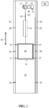
- Figure 2 shows a horizontal cross section of an elevator shaft.
- the cross-section of the shaft 20 is in this embodiment rectangular.
- the horizontal cross section could, however, be of any shape.
- the wall construction 50 of the shaft 20 may comprise a front wall 51, an opposite back wall 52, and two opposite side walls 53, 54.
- the side walls 53, 54 connect the vertical side edges of the front wall 51 and the back wall 52.
- the wall construction 50 of the shaft 20 may be formed of an outer wall 50A and an inner wall 50B.
- the outer wall 50A and the inner wall 50B may be positioned at a horizontal distance from each other.
- the outer wall 50A comprises thus in a corresponding way an outer front wall 51A, an outer back wall 52A and two outer side walls 53A, 54A.
- the inner wall 50B comprises also in a corresponding way an inner front wall 51 B, an inner back wall 52B and two inner side walls 53B, 54B.
- the wall construction 50 may further comprise reinforcement iron 60 in the space between the outer wall 50A and the inner wall 50B.
- the reinforcement iron 60 may comprise horizontally running reinforcement iron 61 and vertically running reinforcement iron 62.
- the figure shows two horizontally running reinforcement iron 61, but there could naturally be any number of horizontally running reinforcement iron 61. Only a part of the vertically running reinforcement iron 62 is shown in the figure.
- Guide rail anchor elements 28 may also be provided in the wall construction 50.
- the fastening brackets 26 may extend between the guide rail anchor elements 28 and the guide rails 25.
- the space between the outer wall 50A and the inner wall 50B is in the final wall construction 50 filled with concrete so that the reinforcement irons 60 and the guide rail anchor elements 28 become embedded into concrete.
- the figure shows also a second direction S2 i.e. the direction between guide rails (DBG) and a third direction S3 i.e. the direction between the front wall 51 and the back wall 52 of the shaft 20.
- the second direction S2 is also the direction between the side walls 53, 54 of the shaft 20.
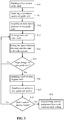
- Figure 3 shows a flow diagram of a method for constructing an elevator shaft and installing guide rails.
- the construction of the shaft 20 and the installation of the guide rails may comprise several consecutive steps.
- a first lowermost section of the elevator shaft 20 comprising a wall construction 50 formed of an outer wall 50A, an inner wall 50B is first built.
- the wall construction 50 may comprise reinforcement iron 60.
- step 911 a first lowermost section of guide rail elements 25 is installed to the walls 50 of the first section of the shaft 20.
- an installation platform 500 is suspended on a second hoist H2 and supported on guide rails 25. At least a concrete printer apparatus 750 may be installed on the installation platform 500. A guide apparatus 700 and an installation apparatus 800 may further be installed on the installation platform 500.
- step 913 the outer 50A and inner wall 50B of the shaft 20 is printed with the concrete printer apparatus 750.
- step 914 the space between the outer wall 50A and the inner wall 50B is filled with concrete. This may be done with the concrete printer apparatus 750.
- step 915 if the wall construction 50 has reached a height corresponding to the height of a new section of guide rail elements 25, then a new section of guide rail elements 25 is installed in step 916, else return to step 913.
- step 917 the installation platform 500 is moved to the next guide rail section.
- step 918 if the shaft 20 has reached the desired height, then stop printing, remove equipment from shaft 20, and construct shaft ceiling in step 919, else return to step 913.
- a lifting frame 600 may further be suspended on a first hoist H1 and supported on guide rails 25.
- the lifting frame 600 may be used to transport material in the shaft 20.
- the installation platform 500 would then be used mainly for installation apparatuses.
- Reinforcement iron 60 may be installed into the wall construction 50 during the printing of the outer wall 50A and the inner wall 50B of the wall construction 50.
- the reinforcement iron 60 may comprise horizontal reinforcement iron 61 and vertical reinforcement iron 62.
- the horizontal reinforcement iron 61 may be installed on a top of the wall construction 50 with an installation apparatus 800.
- the horizontal layer of reinforcement iron 61 may extend into the outer wall 50A and into the inner wall 50B. The inner wall 50A and the outer wall 50B become thus attached to each other via the horizontal reinforcement iron 61.
- the vertical reinforcement iron 62 may also be installed into the wall construction 50 with the installation apparatus 800.
- the vertical reinforcement iron 62 may be positioned in the space between the outer wall 50A and the inner wall 50B.
- the horizontal reinforcement iron 61 and the vertical reinforcement iron 62 may be attached to each other with the installation apparatus 800.
- reinforcement iron 60 may as an alternative be done in one step.
- the reinforcement iron 60 could comprise reinforcement elements comprising horizontal 61 and vertical 62 reinforcement iron attached to each other.
- the reinforcement elements would then be installed as one entity and the different reinforcement elements would be attached to each other.
- anchor elements may be installed into the shaft 20 during the construction of the shaft 20.
- anchor elements may be installed with an installation apparatus 800 into the wall construction 50 of the shaft 20.
- the concrete may also be left to dry after filling the space between the outer wall 50A and the inner wall 50B of the wall construction 50 with concrete.
- the concrete may be left to dry for a predetermined time period. Another possibility is to measure the dryness of the concrete and to decide on the dryness based on the measurements.
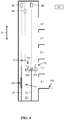
- Figure 4 shows a side view of the shaft during an example of the process.
- a lifting frame 600 and an installation platform 500 have been installed for upward and downward movement on a first section of guide rails 25 in the shaft 20.
- a storage area SA may also be arranged in connection with a first landing L1. The figure shows five landings L1-L5, but there could naturally be any number of landings in the building.
- the lifting frame 600 may be moved upwards and downwards in the shaft 20 with a first hoist H1.
- the lifting frame 600 may be supported on opposite counterweight guide rails 25 with suitable gliding means e.g. glide shoes or rolls gliding on the counterweight guide rails 25.
- the lifting frame 600 may thus be kept laterally in position by the gliding means gliding on the counterweight guide rails 25 during the upwards and downwards movement in the shaft 20.
- the lifting frame 600 may be loaded with guide rail elements 25.
- the guide rail elements 25 may be attached to the lifting frame 600 with snap locking means.
- a second part of the brackets may be attached to the guide rails elements 25 so that the second part of the bracket becomes into contact with the first part of the corresponding bracket when the guide rail 25 is lifted into position in the elevator shaft 20.
- the installation platform 500 may be moved upwards and downwards in the shaft 20 with a second hoist H2.
- the installation platform 500 may be supported on opposite car guide rails 25 with suitable gliding means e.g. glide shoes or rolls gliding on the car guide rails 25.
- suitable gliding means e.g. glide shoes or rolls gliding on the car guide rails 25.
- the installation platform 500 may thus be kept in position in the lateral direction by the gliding means gliding on the car guide rails 25 during the upwards and downwards movement in the shaft 20.
- the installation platform 500 may be provided at least with a concrete printer apparatus 750.
- the installation platform may further be provided with a guide apparatus 700 and an installation apparatus 800.
- the concrete printer apparatus 750, the guide apparatus 700 and the installation apparatus 800 may be installed stationary or movably on the installation platform 500.
- the concrete printer apparatus 750, the guide apparatus 700 and the installation apparatus 800 may be attached on a support frame that moves e.g. on rails on the installation platform 500.
- One or several electric motors could be used to move the support frame on the rails on the installation platform 500.
- the installation platform 500 may then be lifted upwards in the shaft 20 to a position near the prevailing upper end of the shaft 20 with the second hoist H2.
- the guide apparatus 700 could be an industry robot with a pivot arm and gripping means in order to be able to grip guide rails 25 and to lift guide rails into their position on the walls of the elevator shaft 20.
- the arm of the guide apparatus 700 can telescopic so that the guide apparatus 700 can reach upwards above the prevailing upper end of the shaft 20.
- the industry robot may be able to work in any direction.
- the installation apparatus 800 can be based on an industry robot with an arm.
- the installation apparatus 800 may be provided with different working units that can be installed on the arm for performing all the tasks in the fixing steps.
- the arm of the installation apparatus 800 may be telescopic so that the installation apparatus 800 can reach upwards from the prevailing upper end of the shaft 20.
- the industry robot may be able to work in any direction.
- the concrete printer apparatus 750 can be based on an industry robot with an arm.
- the concrete printer apparatus 750 may be provided with a concrete supply pipe having an outlet end.
- the outlet end of the concrete pipe may be steered along the wall construction 50 in order to pour concrete layers on the wall construction 50.
- the arm of the concrete printer apparatus 750 may be telescopic so that the concrete printer apparatus 750 can reach upwards from the prevailing upper end of the shaft 20.
- the industry robot may be able to work in any direction.
- a storage area SA may be arranged on the first landing L1.
- the storage area SA could naturally be arranged at any position below the working level of the installation platform 500.
- the storage area SA could first be positioned on the first landing L1 and then later relocated to a higher landing as the installation advances.
- the guide rail elements 25 may be stored on the storage area SA and loaded on the lifting frame 600 when the lifting frame 600 is empty. The loading of guide rail elements 25 on the lifting frame 600 can be done manually when the lifting frame 600 is in a lower position near the storage area SA.
- a third hoist H3 may further be provided in order to lift guide rails 25 from the lifting frame 600 onto the walls 21 in the shaft 20.
- An attachment device 70 may be provided on a lower end of the rope in the third hoist H3.
- the attachment device 70 may be a hook or a gripping device or some other kind of attachment device suitable for the purpose.
- the first hoists H1, the second hoist H2, and the third hoist H3 may be supported from a support point in the building positioned at a level of the top of the shaft 20 to be built.
- the building of the wall construction 50 may be done in the following way:
- the outer wall 50A and the inner wall 50B may be printed with the concrete printer apparatus 750.
- the space between the outer wall 50A and the inner wall 50B may be filled with concrete. This may be done with the concrete printer 750 or with a concrete pumping apparatus.
- the concrete pumping apparatus may be positioned on the installation platform 500 or on the bottom of the shaft 20 or on a landing L1-L5.
- Reinforcement iron 60 may be installed into the wall construction 50 during the construction of the wall construction 50.
- the installation of the car guide rail elements 25 may be done in the following way: A car guide rail element 25 may be lifted with the third hoist H3 and guided into place with the guide apparatus 700 end-on-end with a corresponding lower car guide rail element 25 in the first section on a first side wall 53 of the shaft 20. The lower end of the first car guide rail element 25 is joined to the upper end of the lower guide rail element with the installation apparatus 800. A fish plate joining the two consecutive guide rail elements may have been attached beforehand on the upper end of the lower guide rail element.
- the support brackets 26 are positioned at suitable distances from each other along the height of the car guide rail element 25. Each support bracket 26 may comprise two parts that are attached to each other with bracket bolts.
- a first wall part of the support bracket 26 may be attached to the anchor element 28 in the wall 50 of the elevator shaft 20 and a second guide rail part may be attached to the guide rail 25.
- the opening of the bracket bolts between the two parts of the support bracket 26 makes it possible to move the two parts of the support bracket 26 in relation to each other.
- the two parts of the support brackets 26 are secured to each other with brackets bolts passing through the two parts of the support brackets 26 when the two consecutive guide rail elements 25 have been joined together.
- the first car guide rail element 25 becomes thus attached through the support brackets 26 to the wall of the elevator shaft 20.
- the bracket bolts may not be finally tightened at this stage so that the car guide rail element 25 can later be adjusted with the alignment tool 400.
- the gripping device 70 of the third hoist H3 is released from the first car guide rail 25.
- the gripping device 70 of the third hoist H3 is then lowered and guided with the guide apparatus 700 to grip an upper end of a second car guide rail element 25 in the lifting frame 600.
- the second opposite car guide rail element 25 in the second section is then lifted with the third hoist H3 from the lifting frame 600 and guided with the guide apparatus 700 into place end-on-end with the corresponding lower car guide rail element 25 in the first section on the opposite side wall 54 of the shaft 20.
- the above described fixing process of the support brackets 26 for the first car guide rail 25 will now be repeated for the second car guide rail 25.
- the gripping device 70 of the third hoist H3 is then released from the second car guide rail 25.
- the counter weight guide rail elements 25 in the second section can be installed in a corresponding way with the guide apparatus 700 and the installation apparatus 800 on the installation platform 500.
- the counter weight rails 25 need may be installed on the back wall 52 or on one of the side walls 53, 54 of the shaft 20.
- a main control unit 80 may control the operation of the hoists H1, H2, H3, the guiding apparatus 700, the installation apparatus 800, and the concrete printing apparatus 750.
- the main control unit 80 receives measurement results from measurement equipment.
- Figure 5 shows an installation apparatus that can be used in the process.
- the installation apparatus 800 may comprise an industry robot 810 attached to a support frame 820 so that the industry robot can be moved in the second direction S2 and in the third direction S3 on the installation platform 500.
- the industry robot 810 may be provided with replaceable working units 830, 840, 850, 860 supported on a support rack attached to the installation apparatus 800.
- the replaceable working units may comprise a drilling unit 830, a bracket installing unit 840, a rail joining unit 850 and a bracket bolting unit 860.
- Figure 6 shows the installation apparatus with a drilling unit.
- the drilling unit 830 is attached to the outer end of the support arm of the industry robot 810.
- the drilling unit 830 may be used to bore the holes into the wall construction 50 of the elevator shaft 20 for the anchor bolts.
- FIG. 7 shows the installation apparatus with a bracket installation unit.
- the bracket installation unit 840 is attached to the outer end of the support arm of the industry robot 850.
- the bracket installation unit 840 may comprise a magnet with which a bracket 26 can be attached to the bracket installation unit 840.
- the bracket 26 may be attached with anchor bolts into holes drilled with the drilling unit 830 into the wall 50.
- Another possibility would be to use the bracket installation unit 840 to attach the bracket 26 onto an anchor element 28 on a wall 50 of the elevator shaft 20.
- the anchor element 28 would in such case have been installed into the wall 50 during the construction of the wall 50. Drilling of holes into the wall 50 would thus not be needed.
- FIG 8 shows the installation apparatus with a rail joining unit.
- the rail joining unit 850 is attached to the outer end of the support arm of the industry robot 850.
- the rail joining unit 850 comprises gripping means which can grip the guide rail 25 after which the guide rail 25 can be guided into position with the robot 810 on the installation apparatus 800.
- the upper end of the guide rail 25 may be supported with the third hoist H3 i.e. most of the weight of the guide rail 25 is carried by the third hoist H3.
- the industry robot 810 does not have to carry the whole weight of the guide rail 25.
- the rail joining unit 850 comprises further a bolt driving apparatus with which the bolts in the joint between the two consecutive guide rails 25 can be tightened.
- the joint can be achieved with a fish plate that has been attached with bolts to the upper end of the lower guide rail element 25 in advance.
- the fish plate is then attached with bolts to the upper guide rail element.
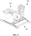
- FIG 9 shows the installation apparatus with a bracket bolting unit.
- the bracket bolting unit 860 is attached to the outer end of the support arm of the industry robot 810.
- the bracket bolting unit 860 is used to open and/or tighten the bracket bolts attaching the two parts in the support brackets 26.
- the opening of the bracket bolts between the two parts of the support bracket 26 makes it possible to move the two parts of the support bracket 26 in relation to each other. This makes it possible to align the guide rails 25.
- the tightening of the brackets bolts locks the two parts of the support bracket 26 in relation to each other.
- the bracket bolting unit 860 may comprise movable arms in order to be able to open and/or tighten the bracket bolts situated at the back farthermost from the bracket bolting unit 860.
- the position of the installation platform 500 in relation to the shaft 20 can be determined in various ways.
- a first possibility would be to install light sources e.g. laser transmitters on a bottom of the elevator shaft 20 and to install position sensitive detectors on the lower surface of the installation platform 500.
- the position of the installation platform 500 can be determined based on the hitting points of the light beams on the position sensitive sensors.
- a second possibility would be to install a robotic total station on the bottom of the elevator shaft 20 and to install reflectors on the lower surface of the installation platform 500.
- the position of the installation platform 500 can be determined with the robotic total station, which measures the position of the reflectors on the installation platform 500 and thereby the position of the installation platform.
- a third possibility would be to install light sources e.g. laser transmitters on the bottom of the elevator shaft 20 and to install digital imaging devices on the installation platform 500.
- the digital imaging devices could be provided with a reflective or transparent screen at a distance in front of the photosensitive sensor of the digital imaging device.
- the reflective or transparent screen could easily be made greater than the photosensitive sensor of the digital imaging device making the possible hitting area for the light beam greater.
- the digital imaging device can take electronic images of either the light beam hitting the photosensitive sensor of the digital imaging device or of a pattern created by the light beam on the reflective or transparent screen.
- the position of the installation platform 500 can be determined from the electronic images taken by the digital imaging device.
- the position of the installation platform 500 in relation to the elevator shaft 20 it is possible to determine the position of the guide apparatus 700 and the installation apparatus 800 positioned on the installation platform 500 in relation to the elevator shaft 20.
- the position of the guide apparatus 700 and the installation apparatus 800 must first be determined in relation to the installation platform 500.
- the guide apparatus 700 and/or the installation apparatus 800 is movably attached to the installation platform 500 sensors are needed on the installation platform 500 in order to determine the position of the guide apparatus 700 and/or the installation apparatus 800 on the installation platform 500.
- the guide apparatus 700 and/or the installation apparatus 800 is stationary attached to the installation platform 500, then the position of the guide apparatus 700 and/or the installation apparatus 800 in relation to the installation platform 500 is stationary.
- the position of the gripping means etc. in the guide apparatus 700 and the installation apparatus 800 is naturally known in relation to the attachment point of the apparatus all the time by the apparatus itself.
- the invention can be used in elevator installations where the hoisting height in the elevator shaft is over 30 m, preferably 30-80 meters, most preferably 40-80 meters.
- the invention can on the other hand also be used in elevator installations where the hoisting height in the elevator shaft is over 75 m, preferably over 100 meters, more preferably over 150 meters, most preferably over 250 meters.
- the use of the invention is not limited to the type of elevator disclosed in the figures.
- the invention can be used in any type of elevator e.g. in elevators with or without a machine room and/or with or without a counterweight.
- the counterweight is in the figures positioned on the back wall of the elevator shaft.
- the counterweight could be positioned on either side wall of the shaft or on both side walls of the elevator shaft.
- the lifting machinery is in the figures positioned at an upper end of the elevator shaft.
- the lifting machinery could be positioned anywhere in the shaft or in a separate machine room.
Landscapes
- Engineering & Computer Science (AREA)
- Architecture (AREA)
- Civil Engineering (AREA)
- Structural Engineering (AREA)
- Lift-Guide Devices, And Elevator Ropes And Cables (AREA)
Abstract
The method may comprise building a first lowermost section of the shaft (20) and installing guide rail elements (25) to the first section of the shaft. An installation platform (500) moving on guide rails transports and supports installation apparatuses. An outer wall (50A) and an inner wall (50B) of the shaft may then be raised upwards after which the space between the outer wall and the inner wall may be filled with concrete. When the wall construction has reached a height of a new section of guide rail elements, then a new section of guide rail elements may be installed to the wall construction.
Description
- The invention relates to a method for elevator shaft construction and guide rail installation.
- An elevator may comprise a car, a shaft, hoisting machinery, ropes, and a counterweight. A separate or an integrated car frame may surround the car.
- The hoisting machinery may be positioned in the shaft. The hoisting machinery may comprise a drive, an electric motor, a traction sheave, and a machinery brake. The hoisting machinery may move the car upwards and downwards in the shaft. The machinery brake may stop the rotation of the traction sheave and thereby the movement of the elevator car.
- The car frame may be connected by the ropes via the traction sheave to the counterweight. The car frame may further be supported with gliding means at guide rails extending in the vertical direction in the shaft. The guide rails may be attached with fastening brackets to the wall structures in the shaft. The gliding means keep the car in position in the horizontal plane when the car moves upwards and downwards in the shaft. The counterweight may be supported in a corresponding way on guide rails that are attached to the wall structure of the shaft.
- The car may transport people and/or goods between the landings in the building.
- The elevator may be controlled by a controller.
- An object of the present invention is to present a novel method for elevator shaft construction and guide rail installation.
- The method for elevator shaft construction and guide rail installation is defined in
claim 1. - The method for elevator shaft construction and guide rail installation comprises:
- building a first lowermost section of an elevator shaft comprising a wall construction formed of an outer wall and an inner wall,
- installing a first lowermost section of guide rail elements to the wall construction of the first lowermost section of the shaft,
- using an installation platform supported on guide rails for upwards and downwards movement in the shaft, at least a concrete printer apparatus being installed on the installation platform,
- raising the outer wall and the inner wall upwards by printing with the concrete printer apparatus,
- filling the space between the outer wall and the inner wall with concrete,
- if the wall construction has reached a height corresponding to the height of a new section of guide rail elements, then install a new section of guide rail elements to the wall construction, else return to the step of raising the outer wall and the inner wall.
- The method makes it possible to simultaneously construct the elevator shaft and to install the guide rails.
- A first lowermost section of the shaft may first be constructed manually or automatically to a height corresponding to the height of a first section of guide rails.
- A lowermost first section of guide rails may then be manually installed to the walls of the first lowermost section of the shaft.
- An installation platform and/or a lifting frame may then be installed on the first lowermost section of the guide rails.
- The further construction of the shaft and the installation of the guide rails may then be done with the help of the installation platform, and the apparatuses provided on the installation platform. Following sections of the shaft may first be constructed automatically with the concrete printer apparatus and the installation apparatus. Following sections of the guide rails may then be installed automatically with the apparatuses provided on the installation platform.
- The invention will in the following be described in greater detail by means of preferred embodiments with reference to the attached drawings, in which:
-
Figure 1 shows a side view of an elevator, -
Figure 2 shows a horizontal cross section of an elevator shaft, -
Figure 3 shows a flow diagram of a method for constructing an elevator shaft and installing guide rails, -
Figure 4 shows a side view of the shaft during an example of the process, -
Figure 5 shows an installation apparatus that can be used in the process, -
Figure 6 shows the installation apparatus with a drilling unit, -
Figure 7 shows the installation apparatus with a bracket installation unit, -
Figure 8 shows the installation apparatus with a rail joining unit, -
Figure 9 shows the installation apparatus with a bracket bolting unit. -
Fig. 1 shows a side view of an elevator. - The elevator may comprise a
car 10, anelevator shaft 20, hoistingmachinery 30, hoistingropes 42, and acounterweight 41. A separate or an integratedcar frame 11 may surround thecar 10. - The hoisting
machinery 30 may be positioned in theshaft 20. The hoisting machinery may comprise a drive 31, anelectric motor 32, atraction sheave 33, and amachinery brake 34. The hoistingmachinery 30 may move thecar 10 in a first vertical direction S1 upwards and downwards in the vertically extendingelevator shaft 20. Themachinery brake 34 may stop the rotation of thetraction sheave 33 and thereby the movement of theelevator car 10. - The
car frame 11 may be connected by theropes 42 via thetraction sheave 33 to thecounterweight 41. Thecar frame 11 may further be supported with gliding means 27 atguide rails 25 extending in the vertical direction in theshaft 20. The gliding means 27 may comprise rolls rolling on theguide rails 25 or gliding shoes gliding on theguide rails 25 when thecar 10 is moving upwards and downwards in theelevator shaft 20. Theguide rails 25 may be attached withfastening brackets 26 to theside wall structures 50 in theelevator shaft 20. The gliding means 27 keep thecar 10 in position in the horizontal plane when thecar 10 moves upwards and downwards in theelevator shaft 20. Thecounterweight 41 may be supported in a corresponding way on guide rails that are attached to thewall structure 50 of theshaft 20. - The
car 10 may transport people and/or goods between the landings in the building. - The elevator may be controlled by a
main control unit 80. -
Figure 2 shows a horizontal cross section of an elevator shaft. - The cross-section of the
shaft 20 is in this embodiment rectangular. The horizontal cross section could, however, be of any shape. Thewall construction 50 of theshaft 20 may comprise afront wall 51, anopposite back wall 52, and twoopposite side walls 53, 54. Theside walls 53, 54 connect the vertical side edges of thefront wall 51 and theback wall 52. Thewall construction 50 of theshaft 20 may be formed of anouter wall 50A and an inner wall 50B. Theouter wall 50A and the inner wall 50B may be positioned at a horizontal distance from each other. Theouter wall 50A comprises thus in a corresponding way an outerfront wall 51A, anouter back wall 52A and twoouter side walls front wall 51 B, aninner back wall 52B and twoinner side walls - The
wall construction 50 may further comprisereinforcement iron 60 in the space between theouter wall 50A and the inner wall 50B. Thereinforcement iron 60 may comprise horizontally runningreinforcement iron 61 and vertically runningreinforcement iron 62. The figure shows two horizontally runningreinforcement iron 61, but there could naturally be any number of horizontally runningreinforcement iron 61. Only a part of the vertically runningreinforcement iron 62 is shown in the figure. - Guide
rail anchor elements 28 may also be provided in thewall construction 50. Thefastening brackets 26 may extend between the guiderail anchor elements 28 and the guide rails 25. - The space between the
outer wall 50A and the inner wall 50B is in thefinal wall construction 50 filled with concrete so that thereinforcement irons 60 and the guiderail anchor elements 28 become embedded into concrete. - The figure shows also a second direction S2 i.e. the direction between guide rails (DBG) and a third direction S3 i.e. the direction between the
front wall 51 and theback wall 52 of theshaft 20. The second direction S2 is also the direction between theside walls 53, 54 of theshaft 20. -
Figure 3 shows a flow diagram of a method for constructing an elevator shaft and installing guide rails. - The construction of the
shaft 20 and the installation of the guide rails may comprise several consecutive steps. - In
step 910, a first lowermost section of theelevator shaft 20 comprising awall construction 50 formed of anouter wall 50A, an inner wall 50B is first built. Thewall construction 50 may comprisereinforcement iron 60. - In
step 911, a first lowermost section ofguide rail elements 25 is installed to thewalls 50 of the first section of theshaft 20. - In
step 912, aninstallation platform 500 is suspended on a second hoist H2 and supported on guide rails 25. At least aconcrete printer apparatus 750 may be installed on theinstallation platform 500. Aguide apparatus 700 and aninstallation apparatus 800 may further be installed on theinstallation platform 500. - In
step 913, the outer 50A and inner wall 50B of theshaft 20 is printed with theconcrete printer apparatus 750. - In
step 914, the space between theouter wall 50A and the inner wall 50B is filled with concrete. This may be done with theconcrete printer apparatus 750. - In
step 915, if thewall construction 50 has reached a height corresponding to the height of a new section ofguide rail elements 25, then a new section ofguide rail elements 25 is installed instep 916, else return to step 913. - In
step 917, theinstallation platform 500 is moved to the next guide rail section. - In
step 918, if theshaft 20 has reached the desired height, then stop printing, remove equipment fromshaft 20, and construct shaft ceiling instep 919, else return to step 913. - A
lifting frame 600 may further be suspended on a first hoist H1 and supported on guide rails 25. Thelifting frame 600 may be used to transport material in theshaft 20. Theinstallation platform 500 would then be used mainly for installation apparatuses. -
Reinforcement iron 60 may be installed into thewall construction 50 during the printing of theouter wall 50A and the inner wall 50B of thewall construction 50. Thereinforcement iron 60 may comprisehorizontal reinforcement iron 61 andvertical reinforcement iron 62. Thehorizontal reinforcement iron 61 may be installed on a top of thewall construction 50 with aninstallation apparatus 800. The horizontal layer ofreinforcement iron 61 may extend into theouter wall 50A and into the inner wall 50B. Theinner wall 50A and the outer wall 50B become thus attached to each other via thehorizontal reinforcement iron 61. - The
vertical reinforcement iron 62 may also be installed into thewall construction 50 with theinstallation apparatus 800. Thevertical reinforcement iron 62 may be positioned in the space between theouter wall 50A and the inner wall 50B. - The
horizontal reinforcement iron 61 and thevertical reinforcement iron 62 may be attached to each other with theinstallation apparatus 800. - The installation of
reinforcement iron 60 may as an alternative be done in one step. Thereinforcement iron 60 could comprise reinforcement elements comprising horizontal 61 and vertical 62 reinforcement iron attached to each other. The reinforcement elements would then be installed as one entity and the different reinforcement elements would be attached to each other. - It is also possible to install anchor elements into the
shaft 20 during the construction of theshaft 20. When the height of theshaft 20 is such that guide rail anchor elements should be installed, then anchor elements may be installed with aninstallation apparatus 800 into thewall construction 50 of theshaft 20. - An alternative solution would be to attach the
guide rail brackets 26 to thewall 50 by drilling holes into thewall 50 and installing anchor bolts into the holes. There would thus not be any need to install anchor elements into thewall 50 during the construction of thewall 50. - The concrete may also be left to dry after filling the space between the
outer wall 50A and the inner wall 50B of thewall construction 50 with concrete. The concrete may be left to dry for a predetermined time period. Another possibility is to measure the dryness of the concrete and to decide on the dryness based on the measurements. -
Figure 4 shows a side view of the shaft during an example of the process. - A
lifting frame 600 and aninstallation platform 500 have been installed for upward and downward movement on a first section ofguide rails 25 in theshaft 20. A storage area SA may also be arranged in connection with a first landing L1. The figure shows five landings L1-L5, but there could naturally be any number of landings in the building. - The
lifting frame 600 may be moved upwards and downwards in theshaft 20 with a first hoist H1. Thelifting frame 600 may be supported on oppositecounterweight guide rails 25 with suitable gliding means e.g. glide shoes or rolls gliding on the counterweight guide rails 25. Thelifting frame 600 may thus be kept laterally in position by the gliding means gliding on thecounterweight guide rails 25 during the upwards and downwards movement in theshaft 20. Thelifting frame 600 may be loaded withguide rail elements 25. Theguide rail elements 25 may be attached to thelifting frame 600 with snap locking means. A second part of the brackets may be attached to theguide rails elements 25 so that the second part of the bracket becomes into contact with the first part of the corresponding bracket when theguide rail 25 is lifted into position in theelevator shaft 20. - The
installation platform 500 may be moved upwards and downwards in theshaft 20 with a second hoist H2. Theinstallation platform 500 may be supported on oppositecar guide rails 25 with suitable gliding means e.g. glide shoes or rolls gliding on the car guide rails 25. Theinstallation platform 500 may thus be kept in position in the lateral direction by the gliding means gliding on thecar guide rails 25 during the upwards and downwards movement in theshaft 20. - The
installation platform 500 may be provided at least with aconcrete printer apparatus 750. The installation platform may further be provided with aguide apparatus 700 and aninstallation apparatus 800. Theconcrete printer apparatus 750, theguide apparatus 700 and theinstallation apparatus 800 may be installed stationary or movably on theinstallation platform 500. Theconcrete printer apparatus 750, theguide apparatus 700 and theinstallation apparatus 800 may be attached on a support frame that moves e.g. on rails on theinstallation platform 500. One or several electric motors could be used to move the support frame on the rails on theinstallation platform 500. There could further be brake means in order to be able to lock the support frame in any desired position on theinstallation platform 500. Theinstallation platform 500 may then be lifted upwards in theshaft 20 to a position near the prevailing upper end of theshaft 20 with the second hoist H2. - The
guide apparatus 700 could be an industry robot with a pivot arm and gripping means in order to be able to grip guide rails 25 and to lift guide rails into their position on the walls of theelevator shaft 20. The arm of theguide apparatus 700 can telescopic so that theguide apparatus 700 can reach upwards above the prevailing upper end of theshaft 20. The industry robot may be able to work in any direction. - The
installation apparatus 800 can be based on an industry robot with an arm. Theinstallation apparatus 800 may be provided with different working units that can be installed on the arm for performing all the tasks in the fixing steps. The arm of theinstallation apparatus 800 may be telescopic so that theinstallation apparatus 800 can reach upwards from the prevailing upper end of theshaft 20. The industry robot may be able to work in any direction. - The
concrete printer apparatus 750 can be based on an industry robot with an arm. Theconcrete printer apparatus 750 may be provided with a concrete supply pipe having an outlet end. The outlet end of the concrete pipe may be steered along thewall construction 50 in order to pour concrete layers on thewall construction 50. The arm of theconcrete printer apparatus 750 may be telescopic so that theconcrete printer apparatus 750 can reach upwards from the prevailing upper end of theshaft 20. The industry robot may be able to work in any direction. - A storage area SA may be arranged on the first landing L1. The storage area SA could naturally be arranged at any position below the working level of the
installation platform 500. The storage area SA could first be positioned on the first landing L1 and then later relocated to a higher landing as the installation advances. Theguide rail elements 25 may be stored on the storage area SA and loaded on thelifting frame 600 when thelifting frame 600 is empty. The loading ofguide rail elements 25 on thelifting frame 600 can be done manually when thelifting frame 600 is in a lower position near the storage area SA. - A third hoist H3 may further be provided in order to lift
guide rails 25 from thelifting frame 600 onto the walls 21 in theshaft 20. Anattachment device 70 may be provided on a lower end of the rope in the third hoist H3. Theattachment device 70 may be a hook or a gripping device or some other kind of attachment device suitable for the purpose. - The first hoists H1, the second hoist H2, and the third hoist H3 may be supported from a support point in the building positioned at a level of the top of the
shaft 20 to be built. - The building of the
wall construction 50 may be done in the following way:
Theouter wall 50A and the inner wall 50B may be printed with theconcrete printer apparatus 750. The space between theouter wall 50A and the inner wall 50B may be filled with concrete. This may be done with theconcrete printer 750 or with a concrete pumping apparatus. The concrete pumping apparatus may be positioned on theinstallation platform 500 or on the bottom of theshaft 20 or on a landing L1-L5.Reinforcement iron 60 may be installed into thewall construction 50 during the construction of thewall construction 50. - The installation of the car
guide rail elements 25 may be done in the following way:
A carguide rail element 25 may be lifted with the third hoist H3 and guided into place with theguide apparatus 700 end-on-end with a corresponding lower carguide rail element 25 in the first section on a first side wall 53 of theshaft 20. The lower end of the first carguide rail element 25 is joined to the upper end of the lower guide rail element with theinstallation apparatus 800. A fish plate joining the two consecutive guide rail elements may have been attached beforehand on the upper end of the lower guide rail element. Thesupport brackets 26 are positioned at suitable distances from each other along the height of the carguide rail element 25. Eachsupport bracket 26 may comprise two parts that are attached to each other with bracket bolts. A first wall part of thesupport bracket 26 may be attached to theanchor element 28 in thewall 50 of theelevator shaft 20 and a second guide rail part may be attached to theguide rail 25. The opening of the bracket bolts between the two parts of thesupport bracket 26 makes it possible to move the two parts of thesupport bracket 26 in relation to each other. The two parts of thesupport brackets 26 are secured to each other with brackets bolts passing through the two parts of thesupport brackets 26 when the two consecutiveguide rail elements 25 have been joined together. The first carguide rail element 25 becomes thus attached through thesupport brackets 26 to the wall of theelevator shaft 20. The bracket bolts may not be finally tightened at this stage so that the carguide rail element 25 can later be adjusted with the alignment tool 400. - The
gripping device 70 of the third hoist H3 is released from the firstcar guide rail 25. Thegripping device 70 of the third hoist H3 is then lowered and guided with theguide apparatus 700 to grip an upper end of a second carguide rail element 25 in thelifting frame 600. The second opposite carguide rail element 25 in the second section is then lifted with the third hoist H3 from thelifting frame 600 and guided with theguide apparatus 700 into place end-on-end with the corresponding lower carguide rail element 25 in the first section on theopposite side wall 54 of theshaft 20. The above described fixing process of thesupport brackets 26 for the firstcar guide rail 25 will now be repeated for the secondcar guide rail 25. Thegripping device 70 of the third hoist H3 is then released from the secondcar guide rail 25. - The counter weight
guide rail elements 25 in the second section can be installed in a corresponding way with theguide apparatus 700 and theinstallation apparatus 800 on theinstallation platform 500. The counter weight rails 25 need may be installed on theback wall 52 or on one of theside walls 53, 54 of theshaft 20. - When all the guide rails 25 in the second section have been installed, then the installation process starts from the beginning in order to install the guide rails in the third section.
- A
main control unit 80 may control the operation of the hoists H1, H2, H3, the guidingapparatus 700, theinstallation apparatus 800, and theconcrete printing apparatus 750. Themain control unit 80 receives measurement results from measurement equipment. -
Figure 5 shows an installation apparatus that can be used in the process. - The
installation apparatus 800 may comprise anindustry robot 810 attached to asupport frame 820 so that the industry robot can be moved in the second direction S2 and in the third direction S3 on theinstallation platform 500. Theindustry robot 810 may be provided with replaceable workingunits installation apparatus 800. The replaceable working units may comprise adrilling unit 830, abracket installing unit 840, arail joining unit 850 and abracket bolting unit 860. -
Figure 6 shows the installation apparatus with a drilling unit. Thedrilling unit 830 is attached to the outer end of the support arm of theindustry robot 810. Thedrilling unit 830 may be used to bore the holes into thewall construction 50 of theelevator shaft 20 for the anchor bolts. -
Figure 7 shows the installation apparatus with a bracket installation unit. Thebracket installation unit 840 is attached to the outer end of the support arm of theindustry robot 850. Thebracket installation unit 840 may comprise a magnet with which abracket 26 can be attached to thebracket installation unit 840. Thebracket 26 may be attached with anchor bolts into holes drilled with thedrilling unit 830 into thewall 50. Another possibility would be to use thebracket installation unit 840 to attach thebracket 26 onto ananchor element 28 on awall 50 of theelevator shaft 20. Theanchor element 28 would in such case have been installed into thewall 50 during the construction of thewall 50. Drilling of holes into thewall 50 would thus not be needed. -
Figure 8 shows the installation apparatus with a rail joining unit. Therail joining unit 850 is attached to the outer end of the support arm of theindustry robot 850. Therail joining unit 850 comprises gripping means which can grip theguide rail 25 after which theguide rail 25 can be guided into position with therobot 810 on theinstallation apparatus 800. The upper end of theguide rail 25 may be supported with the third hoist H3 i.e. most of the weight of theguide rail 25 is carried by the third hoist H3. Theindustry robot 810 does not have to carry the whole weight of theguide rail 25. Therail joining unit 850 comprises further a bolt driving apparatus with which the bolts in the joint between the twoconsecutive guide rails 25 can be tightened. The joint can be achieved with a fish plate that has been attached with bolts to the upper end of the lowerguide rail element 25 in advance. The fish plate is then attached with bolts to the upper guide rail element. -
Figure 9 shows the installation apparatus with a bracket bolting unit. Thebracket bolting unit 860 is attached to the outer end of the support arm of theindustry robot 810. Thebracket bolting unit 860 is used to open and/or tighten the bracket bolts attaching the two parts in thesupport brackets 26. The opening of the bracket bolts between the two parts of thesupport bracket 26 makes it possible to move the two parts of thesupport bracket 26 in relation to each other. This makes it possible to align the guide rails 25. The tightening of the brackets bolts locks the two parts of thesupport bracket 26 in relation to each other. Thebracket bolting unit 860 may comprise movable arms in order to be able to open and/or tighten the bracket bolts situated at the back farthermost from thebracket bolting unit 860. - The position of the
installation platform 500 in relation to theshaft 20 can be determined in various ways. - A first possibility would be to install light sources e.g. laser transmitters on a bottom of the
elevator shaft 20 and to install position sensitive detectors on the lower surface of theinstallation platform 500. The position of theinstallation platform 500 can be determined based on the hitting points of the light beams on the position sensitive sensors. - A second possibility would be to install a robotic total station on the bottom of the
elevator shaft 20 and to install reflectors on the lower surface of theinstallation platform 500. The position of theinstallation platform 500 can be determined with the robotic total station, which measures the position of the reflectors on theinstallation platform 500 and thereby the position of the installation platform. - A third possibility would be to install light sources e.g. laser transmitters on the bottom of the
elevator shaft 20 and to install digital imaging devices on theinstallation platform 500. The digital imaging devices could be provided with a reflective or transparent screen at a distance in front of the photosensitive sensor of the digital imaging device. The reflective or transparent screen could easily be made greater than the photosensitive sensor of the digital imaging device making the possible hitting area for the light beam greater. The digital imaging device can take electronic images of either the light beam hitting the photosensitive sensor of the digital imaging device or of a pattern created by the light beam on the reflective or transparent screen. The position of theinstallation platform 500 can be determined from the electronic images taken by the digital imaging device. - When the position of the
installation platform 500 in relation to theelevator shaft 20 is known it is possible to determine the position of theguide apparatus 700 and theinstallation apparatus 800 positioned on theinstallation platform 500 in relation to theelevator shaft 20. The position of theguide apparatus 700 and theinstallation apparatus 800 must first be determined in relation to theinstallation platform 500. In case theguide apparatus 700 and/or theinstallation apparatus 800 is movably attached to theinstallation platform 500 sensors are needed on theinstallation platform 500 in order to determine the position of theguide apparatus 700 and/or theinstallation apparatus 800 on theinstallation platform 500. In case theguide apparatus 700 and/or theinstallation apparatus 800 is stationary attached to theinstallation platform 500, then the position of theguide apparatus 700 and/or theinstallation apparatus 800 in relation to theinstallation platform 500 is stationary. The position of the gripping means etc. in theguide apparatus 700 and theinstallation apparatus 800 is naturally known in relation to the attachment point of the apparatus all the time by the apparatus itself. - The invention can be used in elevator installations where the hoisting height in the elevator shaft is over 30 m, preferably 30-80 meters, most preferably 40-80 meters.
- The invention can on the other hand also be used in elevator installations where the hoisting height in the elevator shaft is over 75 m, preferably over 100 meters, more preferably over 150 meters, most preferably over 250 meters.
- The use of the invention is not limited to the type of elevator disclosed in the figures. The invention can be used in any type of elevator e.g. in elevators with or without a machine room and/or with or without a counterweight. The counterweight is in the figures positioned on the back wall of the elevator shaft. The counterweight could be positioned on either side wall of the shaft or on both side walls of the elevator shaft. The lifting machinery is in the figures positioned at an upper end of the elevator shaft. The lifting machinery could be positioned anywhere in the shaft or in a separate machine room.
- It will be obvious to a person skilled in the art that, as the technology advances, the inventive concept can be implemented in various ways. The invention and its embodiments are not limited to the examples described above but may vary within the scope of the claims.
Claims (11)
- A method for elevator shaft construction and guide rail installation, said method comprising
building a first lowermost section of an elevator shaft (20) comprising a wall construction (50) formed of an outer wall (50A) and an inner wall (50B),
installing a first lowermost section of guide rail elements (25) to the wall construction (50) of the first lowermost section of the shaft (20),
using an installation platform (500) supported on guide rails (25) for upwards and downwards movement in the shaft (20), at least a concrete printer apparatus (750) being installed on the installation platform (500),
raising the outer wall (50A) and the inner wall (50B) upwards by printing with the concrete printer apparatus (750),
filling the space between the outer wall (50A) and the inner wall (50B) with concrete,
if the wall construction (50) has reached a height corresponding to the height of a new section of guide rail elements (25), then install a new section of guide rail elements (25) to the wall construction (50), else return to the step of raising the outer wall (50A) and the inner wall (50B). - The method according to claim 1, wherein
a lifting frame (600) supported on guide rails (25) is used to transport material in the shaft (20). - The method according to claim 1 or 2, wherein
a guide apparatus (700) and an installation apparatus (800) is further installed on the installation platform (500). - The method according to any one of claims 1 to 3, wherein
reinforcement iron (60) is installed into the wall construction (50) during the construction of the wall construction (50). - The method according to any one of claims 1 to 4, wherein anchor elements (28) for the attachment of the guide rail elements (25) are installed into the wall construction (50) during the construction of the wall construction (50).
- The method according to any one of claims 1 to 5, wherein support brackets (26) are installed into the walls (50) of the elevator shaft (20) with a bracket installation unit (830) provided on the installation apparatus (800).
- The method according to any one of claims 1 to 6, wherein two consecutive guide rail elements (25) are joined in the elevator shaft (20) with a rail joining unit (840) provided on the installation apparatus (800).
- The method according to any one of claims 1 to 7, wherein the support brackets (26) and thereby the guide rail element (25) are locked in the elevator shaft (20) with a bracket bolting unit (850) provided on the installation apparatus (800).
- An arrangement for elevator shaft construction and guide rail installation comprising
an installation platform (500) being suspended with a second hoist (H2) and supported on guide rails (25), at least a concrete printer apparatus (750) being installed on the installation platform (500), whereby:a first lowermost section of an elevator shaft (20) comprising a wall construction (50) formed of an outer wall (50A) and an inner wall (50B) is built,a first lowermost section of guide rail elements (25) is installed to the wall construction (50) of the first lowermost section of the shaft (20),the outer wall (50A) and the inner wall (50B) is raised upwards by printing with the concrete printer apparatus (750),the space between the outer wall (50A) and the inner wall (50B) is filled with concrete,if the wall construction (50) has reached a height corresponding to the height of a new section of guide rail elements (25), then install a new section of guide rail elements (25) to the wall construction (50), else return to the step of raising the outer wall (50A) and the inner wall (50B). - The arrangement according to claim 9, wherein
a lifting frame (600) is suspended with a first hoist (H1) and supported on guide rails (25), the lifting frame (600) being used to transport material in the shaft (20). - The arrangement according to claim 9 or 10, wherein
a guide apparatus (700) and an installation apparatus (800) is further installed on the installation platform (500).
Priority Applications (1)
| Application Number | Priority Date | Filing Date | Title |
|---|---|---|---|
| EP19167005.8A EP3718945A1 (en) | 2019-04-03 | 2019-04-03 | A method for elevator shaft construction and guide rail installation |
Applications Claiming Priority (1)
| Application Number | Priority Date | Filing Date | Title |
|---|---|---|---|
| EP19167005.8A EP3718945A1 (en) | 2019-04-03 | 2019-04-03 | A method for elevator shaft construction and guide rail installation |
Publications (1)
| Publication Number | Publication Date |
|---|---|
| EP3718945A1 true EP3718945A1 (en) | 2020-10-07 |
Family
ID=66092036
Family Applications (1)
| Application Number | Title | Priority Date | Filing Date |
|---|---|---|---|
| EP19167005.8A Withdrawn EP3718945A1 (en) | 2019-04-03 | 2019-04-03 | A method for elevator shaft construction and guide rail installation |
Country Status (1)
| Country | Link |
|---|---|
| EP (1) | EP3718945A1 (en) |
Cited By (1)
| Publication number | Priority date | Publication date | Assignee | Title |
|---|---|---|---|---|
| WO2023227823A1 (en) * | 2022-05-25 | 2023-11-30 | Kone Corporation | Drilling arrangement for drilling holes to a wall of an elevator shaft for fastening a guide rail to the wall, use of such drilling arrangement and method of drilling holes to a wall of an elevator shaft using such drilling arrangement |
Citations (3)
| Publication number | Priority date | Publication date | Assignee | Title |
|---|---|---|---|---|
| EP1321418A1 (en) * | 2001-12-21 | 2003-06-25 | Inventio Ag | Elevator shaft |
| US20120168263A1 (en) * | 2011-01-05 | 2012-07-05 | Alois Dominick J | Elevator liner apparatus and utilization method thereof |
| CN108824763A (en) * | 2018-06-04 | 2018-11-16 | 菱王电梯股份有限公司 | Pin-connected panel elevator pit |
-
2019
- 2019-04-03 EP EP19167005.8A patent/EP3718945A1/en not_active Withdrawn
Patent Citations (3)
| Publication number | Priority date | Publication date | Assignee | Title |
|---|---|---|---|---|
| EP1321418A1 (en) * | 2001-12-21 | 2003-06-25 | Inventio Ag | Elevator shaft |
| US20120168263A1 (en) * | 2011-01-05 | 2012-07-05 | Alois Dominick J | Elevator liner apparatus and utilization method thereof |
| CN108824763A (en) * | 2018-06-04 | 2018-11-16 | 菱王电梯股份有限公司 | Pin-connected panel elevator pit |
Cited By (1)
| Publication number | Priority date | Publication date | Assignee | Title |
|---|---|---|---|---|
| WO2023227823A1 (en) * | 2022-05-25 | 2023-11-30 | Kone Corporation | Drilling arrangement for drilling holes to a wall of an elevator shaft for fastening a guide rail to the wall, use of such drilling arrangement and method of drilling holes to a wall of an elevator shaft using such drilling arrangement |
Similar Documents
| Publication | Publication Date | Title |
|---|---|---|
| EP3085660B1 (en) | A method and an arrangement for installing elevator guide rails | |
| EP3766819B1 (en) | A method and an arrangement for installing elevator guide rails into an elevator shaft | |
| CN1102908C (en) | Method and device for installing a shaft installation of an elevator | |
| US7997000B2 (en) | Arrangement and method for positioning the alignment plumb lines of the guide rails of an elevator | |
| CN114585581A (en) | Self-climbing installation platform for installation of elevators during building construction | |
| EP4486678A1 (en) | An elevator construction arrangement and a method | |
| CN114829288A (en) | Elevator apparatus and method | |
| EP2043938B1 (en) | Elevators | |
| WO2020142001A1 (en) | A moveable platform | |
| US12103819B2 (en) | Construction arrangement of an elevator and method | |
| JP2878936B2 (en) | Elevator installation method | |
| JP3920527B2 (en) | Elevator for construction | |
| JP2001335255A (en) | Elevator installation method and elevator installation unit | |
| CN116710382A (en) | Method, device and transport device for transporting elevator guide rails in shafts | |
| US20250326607A1 (en) | Unlocking device and unlocking method of elevator landing door, and elevator system | |
| CN223620017U (en) | Counterweight leveling lifting device suitable for curtain wall lifting operation under cornice | |
| HK40038218A (en) | A method and an arrangement for installing elevator guide rails into an elevator shaft | |
| HK1230572A1 (en) | A method and an arrangement for installing elevator guide rails | |
| JPH08338136A (en) | Lifting equipment for construction | |
| JPH07243262A (en) | Installation of exterior curtain wall Measurement control device and control method for lifting platform | |
| HK40038218B (en) | A method and an arrangement for installing elevator guide rails into an elevator shaft | |
| CN118148380A (en) | Lifting and conveying device for large-span overweight steel corridor suspension platform and construction method | |
| HK1230572B (en) | A method and an arrangement for installing elevator guide rails | |
| JPH05278966A (en) | Temporary elevator device |
Legal Events
| Date | Code | Title | Description |
|---|---|---|---|
| PUAI | Public reference made under article 153(3) epc to a published international application that has entered the european phase |
Free format text: ORIGINAL CODE: 0009012 |
|
| STAA | Information on the status of an ep patent application or granted ep patent |
Free format text: STATUS: THE APPLICATION HAS BEEN PUBLISHED |
|
| AK | Designated contracting states |
Kind code of ref document: A1 Designated state(s): AL AT BE BG CH CY CZ DE DK EE ES FI FR GB GR HR HU IE IS IT LI LT LU LV MC MK MT NL NO PL PT RO RS SE SI SK SM TR |
|
| AX | Request for extension of the european patent |
Extension state: BA ME |
|
| STAA | Information on the status of an ep patent application or granted ep patent |
Free format text: STATUS: THE APPLICATION IS DEEMED TO BE WITHDRAWN |
|
| 18D | Application deemed to be withdrawn |
Effective date: 20210108 |