EP3718941A1 - Elevator control device, elevator, and elevator control method - Google Patents
Elevator control device, elevator, and elevator control method Download PDFInfo
- Publication number
- EP3718941A1 EP3718941A1 EP17933672.2A EP17933672A EP3718941A1 EP 3718941 A1 EP3718941 A1 EP 3718941A1 EP 17933672 A EP17933672 A EP 17933672A EP 3718941 A1 EP3718941 A1 EP 3718941A1
- Authority
- EP
- European Patent Office
- Prior art keywords
- elevator
- maintenance worker
- elevator car
- maintenance
- switch
- Prior art date
- Legal status (The legal status is an assumption and is not a legal conclusion. Google has not performed a legal analysis and makes no representation as to the accuracy of the status listed.)
- Granted
Links
Images


Classifications
-
- B—PERFORMING OPERATIONS; TRANSPORTING
- B66—HOISTING; LIFTING; HAULING
- B66B—ELEVATORS; ESCALATORS OR MOVING WALKWAYS
- B66B5/00—Applications of checking, fault-correcting, or safety devices in elevators
- B66B5/0043—Devices enhancing safety during maintenance
- B66B5/005—Safety of maintenance personnel
-
- B—PERFORMING OPERATIONS; TRANSPORTING
- B66—HOISTING; LIFTING; HAULING
- B66B—ELEVATORS; ESCALATORS OR MOVING WALKWAYS
- B66B5/00—Applications of checking, fault-correcting, or safety devices in elevators
-
- B—PERFORMING OPERATIONS; TRANSPORTING
- B66—HOISTING; LIFTING; HAULING
- B66B—ELEVATORS; ESCALATORS OR MOVING WALKWAYS
- B66B5/00—Applications of checking, fault-correcting, or safety devices in elevators
- B66B5/0043—Devices enhancing safety during maintenance
- B66B5/005—Safety of maintenance personnel
- B66B5/0081—Safety of maintenance personnel by preventing falling by means of safety fences or handrails, being operable or not, mounted on top of the elevator car
Definitions
- the pit maintenance operation device 15 has functions similar to the car top maintenance operation device 12 explained earlier and is installed in the pit.
- the pit maintenance operation device 15 has a pit side operation mode selector switch 15a, a pit side lift switch 15b, a pit side down switch 15c, a pit side travel switch 15d, and a pit side car stop switch 15e.
- the respective switches function similarly to the respective switches installed in the car top maintenance operation device 12.
- the elevator control device 100 is for controlling operation of the elevator 1 in a normal mode and a maintenance mode including drive of the hoisting machine 2 for lifting and lowering the elevator car 4 and open and close of the car door that is a door installed in the elevator car 4. Further, the elevator control device 100 judges whether or not the operation mode may be switched on the basis of signals from switches, detectors, and moreover the governor encoder 6.
- the site where the elevator control device 100 is installed is not limited and, as an example, the elevator control device 100 may be installed in any of the interior of the pit 1b, a machine room (not shown in the figure) at an upper part of the hoistway 1a, and the platform floors 1f.
- the elevator control device 100 includes a calculator such as a microcomputer.
- the calculator has a CPU (Central Processing Unit), a ROM (Read Only Memory), and a RAM (Random Access Memory). Further, the calculator has an input section including a buffer circuit.
- CPU Central Processing Unit
- ROM Read Only Memory
- RAM Random Access Memory
- the switch confirmation unit 103 is a unit to confirm the state of a judgment switch to judge whether or not the operation mode of an elevator 1 may be switched.
- the judgment switch is any of a car top stop switch 11, an operation mode selector switch 12a, a pit side operation mode selector switch 15a, and a handrail switch 13a. Further, although the figure is not shown here, a car stop switch 12e and a pit side car stop switch 15e are also captured by an input buffer identical to the contact point of the car top stop switch 11 and hence act as judgment switches.
- the switch confirmation unit 103 judges whether all of those judgment switches are on a normal mode side or on a maintenance mode side.
- a first elevator control method explained here is a method of mode switching process from a normal mode to a maintenance mode implemented by an elevator control device 100 when operation work of an elevator 1 starts.
- a second elevator control method is a method of return process from a maintenance mode to a normal mode implemented by an elevator control device 100 when operation work of an elevator 1 finishes.
- a maintenance worker implements the following operations when maintenance work of an elevator 1 starts. Firstly, the maintenance worker opens a platform door 14 (S1). This allows a platform door open/close detector 14a to detect an off state. Successively, the maintenance worker boards an upper part of an elevator car 4 (S2). This makes the elevator car 4 heavier and lower and a governor encoder 6 detects a minute change in the lowering of the elevator car 4. Further, the maintenance worker immediately presses a car top stop switch 11 (S3). This turns the car top stop switch 11 off. Successively, the maintenance worker assembles a handrail 13 and switches an operation mode selector switch 12a of a car top maintenance operation device 12 to a maintenance mode (S4). This makes a handrail switch 13a off and a maintenance mode side on and a normal mode side off in the operation mode selector switch 12a.
- the maintenance worker implements maintenance work of the elevator 1 by operation of an operation switch of the car top maintenance operation device 12 (S5).
- the operation switch includes a lift switch 12b, a down switch 12c, and a travel switch 12d.
- Figure 5 is a flowchart showing a first elevator control method according to an embodiment.
- the procedures shown in the figure are procedures of mode switching process from a normal mode to a maintenance mode implemented by an elevator control device 100 when maintenance work of an elevator 1 starts, and include the following steps.
- a platform door open/close judgment unit 102 judges whether or not a platform door 14 opens. On this occasion, the platform door open/close judgment unit 102 judges that the platform door 14 has opened (YES) from a close state because a platform door open/close detector 14a reverses from on to off and the process advances to the next Step S102. On other occasions, the platform door open/close judgment unit 102 judges that the platform door 14 does not open (NO) and Step S101 is repeated.
- Step S105 By judging at Step S105 that a maintenance worker boards an upper part of the elevator car 4 (YES), it can be judged that a maintenance worker M has opened a platform door 14 (operation S1 in Figure 4 ) and successively has boarded an upper part of the elevator car 4 (operation S2 in Figure 4 ). Further, by the judgment, it is confirmed that a maintenance worker M boards an upper part of the elevator car 4 in the state of judging that all the judgment switches have switched to a maintenance mode side (YES) at Step S103.
- safety can be improved in maintenance work of an elevator 1. Moreover, safety can be improved at a low cost without the need of installing specific equipment at each of platform floors 1f.
- the predetermined time in the above judgment may be any time as long as it is enough time for a maintenance worker having left an elevator car 4 to close a platform door 14, and is set at a time in about one to three minutes as an example.
Landscapes
- Maintenance And Inspection Apparatuses For Elevators (AREA)
Abstract
Description
- The present invention relates to an elevator control device, an elevator, and an elevator control method.
- There is a technology disclosed in Japanese Unexamined Patent Application Publication No.
2016-117558 elevator car 1 is braked undesirably and raising and lowering theelevator car 1 becomes impossible while the maintenance worker performs inspection work on theelevator car 1". - PTL 1: Japanese Unexamined Patent Application Publication No.
2016-117558 - By the technology described in
PTL 1, however, a maintenance worker on an elevator car is at risk if an elevator operation mode is wrongly restored to a normal mode even in a state where the maintenance worker is on the elevator car. - In view of the above situation, an object of the present invention is to provide an elevator control device, an elevator, and an elevator control method, which are capable of improving safety in maintenance work of an elevator.
- The configuration described in CLAIMS is adopted for example in order to solve the above problem. The present application includes a plurality of means for solving the above problem and an example of the means is as follows: an elevator control device having an operation control unit to control operation of an elevator in accordance with an operation mode selected by a selector switch installed at an upper part of an elevator car includes a maintenance worker boarding/leaving judgment unit to judge whether a maintenance worker boards or leaves the elevator car on the basis of a signal from a governor encoder for detecting a travel distance of the elevator car in a hoistway, and a switch operation permission unit to permit the operation control unit to operate in an operation mode selected by the selector switch on the basis of a state where the maintenance worker boards or leaves the elevator car judged at the maintenance worker boarding/leaving judgment unit.
- The present invention of the above configuration makes it possible to provide an elevator control device, an elevator, and an elevator control method, which are capable of improving safety of a maintenance worker in maintenance work of an elevator.
- Problems, configurations, and effects other than the above descriptions will be obvious from the explanations of the following embodiments.
-
-
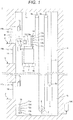
Figure 1 is a general configuration diagram of an elevator according to an embodiment. -
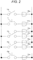
Figure 2 is a circuit diagram of switches and detectors involved in maintenance work of an elevator according to an embodiment. -
Figure 3 is a block diagram of an elevator control device according to an embodiment. -
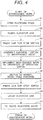
Figure 4 is a flowchart showing procedures of maintenance work of an elevator by a maintenance worker. -
Figure 5 is a flowchart showing a first elevator control method according to an embodiment. -
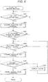
Figure 6 is a flowchart showing a second elevator control method according to an embodiment. -
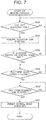
Figure 7 is a flowchart showing a modified example of the second elevator control method according to an embodiment. - Embodiments relating to an elevator control device, an elevator, and an elevator control method according to the present invention are hereunder explained in detail in reference to the drawings. Here, in the embodiments explained below, firstly a general configuration of an elevator is explained and successively an elevator control device installed in the elevator and an elevator control method implemented by the elevator control device are explained.
-
Figure 1 is a general configuration diagram showing an example of anelevator 1 to which an elevator control device and an elevator control method according to an embodiment are applied. As shown inFigure 1 , theelevator 1 has ahoistway 1a installed in the manner of vertically penetrating the interior of a building or the like. The lower part of thehoistway 1a constitutes apit 1b formed by being dug from the bottom floor of a building. - The
elevator 1 has a hoistingmachine 2, arope 3, anelevator car 4, acounterweight 5, agovernor encoder 6, and a PosiTector 7 in thehoistway 1a. A cartop stop switch 11, a car topmaintenance operation device 12, and a handrail 13 are installed at the upper part of theelevator car 4. Further, theelevator 1 hasplatform doors 14 at positions corresponding torespective platform floors 1f over a sidewall of thehoistway 1a, and a pitmaintenance operation device 15 in thepit 1b at the lower part of thehoistway 1a. Furthermore, theelevator 1 has anelevator control device 100 for controlling operation of theelevator car 4 and operation of switching an operation mode between a normal mode and a maintenance mode is implemented. Those components constituting theelevator 1 are explained hereunder. - The hoisting
machine 2 is fixed to the interior of thepit 1b of thehoistway 1a in the state of wrapping therope 3. The hoistingmachine 2 has a motor not shown in the figure and is configured so as to move therope 3 by the rotation of the hoistingmachine 2. - The
rope 3 is for hanging theelevator car 4 and thecounterweight 5. For example, both the ends of therope 3 are fixed to aceiling 1c of thehoistway 1a and therope 3 is wrapped at intermediate parts around twopulleys 3a fixed to theceiling 1c and is wrapped around the hoistingmachine 2 and thecounterweight 5 respectively between the twopulleys 3a and the fixed part. The rope 3 lifts and lowers theelevator car 4 and thecounterweight 5 freely in thehoistway 1a by the drive of the hoistingmachine 2. - The
elevator car 4 is for carrying people and luggage and is installed in the state of being hanged in thehoistway 1a by therope 3. For example, therope 3 is wrapped aroundcar pulleys 4a fixed to an upper part or a lower part of theelevator car 4, and theelevator car 4 rises or lowers vertically in thehoistway 1a in accordance with rotation of the hoistingmachine 2. Theelevator car 4 has a car door (not shown in the figure) that slides horizontally to open and close at a position facing theplatform doors 14 installed at thehoistway 1a. Further, an operation button (not shown in the figure) for controlling a designation of theelevator car 4 and opening and closing of the car door and contacting outside in the event of an emergency is installed at a position close to the car door. - The
counterweight 5 is for balancing theelevator car 4 and is installed in the state of being hung in thehoistway 1a by therope 3. Acounterweight pulley 5a is fixed to thecounterweight 5 and therope 3 is wrapped around thecounterweight pulley 5a. As a result, thecounterweight 5 rises and lowers in a vertical direction opposite to theelevator car 4 in thehoistway 1a in accordance with rotation of the hoistingmachine 2. - The
governor encoder 6 detects the number of revolutions of thehoisting machine 2 and is installed in the hoistingmachine 2 as a travel distance detection means for detecting a travel distance of theelevator car 4. Thegovernor encoder 6 is connected to theelevator control device 100 so that information on the detected number of revolutions of the hoistingmachine 2 may be transmitted to theelevator control device 100. In particular, thegovernor encoder 6 acts as one of detectors to judge whether or not the operation mode of theelevator 1 may be switched. - The PosiTector 7 outputs a signal to judge whether or not the
elevator car 4 is located at a position of allowing the car door installed in theelevator car 4 to be opened. For example, the PosiTector 7 includeslight shielding plates 7a formed in the manner of protruding from the inner wall of thehoistway 1a and anoptical sensor 7b formed in the manner of protruding from the outer wall of theelevator car 4 toward the inner wall of thehoistway 1a. Then whether or not theelevator car 4 is located at a platform floor is detected by the output of an on/off signal from the optical sensor. - The car
top stop switch 11 is a switch for stopping the travel of theelevator car 4 in thehoistway 1a. The cartop stop switch 11 is installed at a position close to aplatform door 14 at an upper part of theelevator car 4 and is arranged at a position where a maintenance worker M who has opened aplatform door 14 can press the switch immediately from aplatform floor 1f. The cartop stop switch 11 is connected to theelevator control device 100 and acts as one of judgment switches to judge whether or not the operation mode of theelevator 1 may be switched. - The car top
maintenance operation device 12 is a device for a maintenance worker M to operate the travel of theelevator car 4 for maintenance and inspection of theelevator 1. For example, the car topmaintenance operation device 12 has an operationmode selector switch 12a, alift switch 12b, adown switch 12c, atravel switch 12d, and acar stop switch 12e. - In the switches, the operation
mode selector switch 12a is a switch for selecting the operation mode of theelevator 1 between a normal mode and a maintenance mode. Thelift switch 12b, thedown switch 12c, and thetravel switch 12d are operation switches for the maintenance worker M to operate and move theelevator car 4 when the operation mode is switched to the maintenance mode. Further, thecar stop switch 12e is one of switches for stopping the travel of theelevator car 4 and functions similarly to the cartop stop switch 11. - The car top
maintenance operation device 12 having such respective switches is connected to theelevator control device 100. Then in particular, the operationmode selector switch 12a and thecar stop switch 12e are also judgment switches to judge whether or not the operation mode of theelevator 1 may be switched. - The handrail 13 is a freely assembled frame member installed at an upper part of the
elevator car 4. Ahandrail switch 13a that switches on or off by assembling the handrail 13 is installed in the handrail 13. Thehandrail switch 13a is connected to theelevator control device 100 and acts as one of switches to judge whether or not the operation mode of theelevator 1 may be switched. - The
platform doors 14 are installed at positions of the heights ofrespective platform floors 1f where theelevator car 4 stops over a wall surface of thehoistway 1a. Each of theplatform doors 14 slides to open and close in the horizontal direction, does not have a unique power, and opens and closes following a car door by engaging with the car door of theelevator car 4. Further, a platform door open/close detector 14a that is turned off by the opening of the door is installed in each of theplatform doors 14. Each of the platform door open/close detectors 14a is connected to theelevator control device 100 that will be explained later and acts as one of detectors to judge whether or not the operation mode of theelevator 1 may be switched. - The pit
maintenance operation device 15 has functions similar to the car topmaintenance operation device 12 explained earlier and is installed in the pit. For example, the pitmaintenance operation device 15 has a pit side operationmode selector switch 15a, a pitside lift switch 15b, a pit side downswitch 15c, a pitside travel switch 15d, and a pit sidecar stop switch 15e. The respective switches function similarly to the respective switches installed in the car topmaintenance operation device 12. - The pit
maintenance operation device 15 is connected to theelevator control device 100. Then the pit side operationmode selector switch 15a and the pit sidecar stop switch 15e act as judgment switches to judge whether or not the operation mode of theelevator 1 may be switched. - The
elevator control device 100 is for controlling operation of theelevator 1 in a normal mode and a maintenance mode including drive of the hoistingmachine 2 for lifting and lowering theelevator car 4 and open and close of the car door that is a door installed in theelevator car 4. Further, theelevator control device 100 judges whether or not the operation mode may be switched on the basis of signals from switches, detectors, and moreover thegovernor encoder 6. The site where theelevator control device 100 is installed is not limited and, as an example, theelevator control device 100 may be installed in any of the interior of thepit 1b, a machine room (not shown in the figure) at an upper part of thehoistway 1a, and theplatform floors 1f. - The
elevator control device 100 includes a calculator such as a microcomputer. The calculator has a CPU (Central Processing Unit), a ROM (Read Only Memory), and a RAM (Random Access Memory). Further, the calculator has an input section including a buffer circuit. -
Figure 2 is a circuit diagram of switches and detectors involved in maintenance work of an elevator according to an embodiment. As shown in the figure, in anelevator control device 100, a contact point of a platform door open/close detector 14a is captured by an input buffer 14bu. Here, for example, the platform door open/close detector 14a is a detector that is turned on in the state of closing aplatform door 14 and turned off in the state of opening aplatform door 14, the platform door open/close detectors 14a at respective floors are connected in series, and the input buffer 14bu is in an off state when one of the multiple platform door open/close detectors 14a is turned off. - Further, in the
elevator control device 100, a contact point of a cartop stop switch 11 is captured by an input buffer 11bu. Here, the cartop stop switch 11 is regarded as a switch to stop an elevator car in the state of off as an example. On this occasion, the cartop stop switch 11 is connected in series to acar stop switch 12e and a pit sidecar stop switch 15e, those having similar functions. Then by one of the switches being off, the input buffer 11bu is in the state of off. - Further, in the
elevator control device 100, the contact point on the normal mode side is captured by an input buffer 12bu and the contact point on the maintenance mode side is captured by an input buffer 12bu' in the contact points of an operationmode selector switch 12a of a car topmaintenance operation device 12. Likewise, the contact point on the normal mode side is captured by an input buffer 15bu and the contact point on the maintenance mode side is captured by an input buffer 15bu' in the contact points of a pit side operationmode selector switch 15a of a pitmaintenance operation device 15. Moreover, in theelevator control device 100, a contact point of ahandrail switch 13a is captured by an input buffer 13bu. -
Figure 3 is a block diagram of anelevator control device 100 according to an embodiment. As shown in the figure, theelevator control device 100 has, as respective parts for judging whether or not the operation mode of anelevator 1 should be switched, a maintenance worker boarding/leavingjudgment unit 101, a platform door open/close judgment unit 102, aswitch confirmation unit 103, a switchoperation permission unit 104, and anoperation control unit 105. Those respective units have the functions explained below. A CPU in theelevator control device 100 reads and runs programs stored in a ROM, and thus implements the functions. - The maintenance worker boarding/leaving
judgment unit 101 monitors a signal from agovernor encoder 6. Further, the maintenance worker boarding/leavingjudgment unit 101 acquires a position of anelevator car 4 on the basis of the signal from thegovernor encoder 6. Furthermore, the maintenance worker boarding/leavingjudgment unit 101 judges whether a maintenance worker boards or leaves theelevator car 4 on the basis of change of the monitored signal of thegovernor encoder 6 and the acquired position of the elevator car. - The platform door open/
close judgment unit 102 judges whether aplatform door 14 closes or opens on the basis of a signal from a platform door open/close detector 14a. Further, the platform door open/close judgment unit 102 judges whether aplatform door 14 has changed from an open state to a close state or from a close state to an open state on the basis of a signal from the platform door open/close detector 14a. - The
switch confirmation unit 103 is a unit to confirm the state of a judgment switch to judge whether or not the operation mode of anelevator 1 may be switched. The judgment switch is any of a cartop stop switch 11, an operationmode selector switch 12a, a pit side operationmode selector switch 15a, and ahandrail switch 13a. Further, although the figure is not shown here, acar stop switch 12e and a pit sidecar stop switch 15e are also captured by an input buffer identical to the contact point of the cartop stop switch 11 and hence act as judgment switches. - The
switch confirmation unit 103 judges whether all of those judgment switches are on a normal mode side or on a maintenance mode side. - The switch
operation permission unit 104 permits theoperation control unit 105 to operate in a switched operation mode when an operation mode is switched by the operationmode selector switch 12a of a car topmaintenance operation device 12. In particular, the switchoperation permission unit 104 is connected to the maintenance worker boarding/leavingjudgment unit 101, the platform door open/close judgment unit 102, and theswitch confirmation unit 103 and permits operation in an operation mode selected by switching the operationmode selector switch 12a on the basis of judgments at those units. - The
operation control unit 105 controls operation of theelevator 1 in an operation mode selected by switching the operationmode selector switch 12a of the car topmaintenance operation device 12 when the switchoperation permission unit 104 permits. - Meanwhile, functions included in the respective units constituting the aforementioned
elevator control device 100 are explained in more detail in the following elevator control method. - An elevator control method by an
elevator control device 100 explained in reference toFigures 2 and3 is explained hereunder. A first elevator control method explained here is a method of mode switching process from a normal mode to a maintenance mode implemented by anelevator control device 100 when operation work of anelevator 1 starts. Further, a second elevator control method is a method of return process from a maintenance mode to a normal mode implemented by anelevator control device 100 when operation work of anelevator 1 finishes. -
Figure 4 is a flowchart showing procedures of maintenance work of an elevator by a maintenance worker. A series of operations implemented by a maintenance worker are explained hereunder in reference toFigure 4 before the elevator control methods implemented by anelevator control device 100 are explained. Here, the states of switches operated in respective operations are explained together. - A maintenance worker implements the following operations when maintenance work of an
elevator 1 starts. Firstly, the maintenance worker opens a platform door 14 (S1). This allows a platform door open/close detector 14a to detect an off state. Successively, the maintenance worker boards an upper part of an elevator car 4 (S2). This makes theelevator car 4 heavier and lower and agovernor encoder 6 detects a minute change in the lowering of theelevator car 4. Further, the maintenance worker immediately presses a car top stop switch 11 (S3). This turns the cartop stop switch 11 off. Successively, the maintenance worker assembles a handrail 13 and switches an operationmode selector switch 12a of a car topmaintenance operation device 12 to a maintenance mode (S4). This makes ahandrail switch 13a off and a maintenance mode side on and a normal mode side off in the operationmode selector switch 12a. - After the operation
mode selector switch 12a is switched to the maintenance mode by implementing the above procedures, the maintenance worker implements maintenance work of theelevator 1 by operation of an operation switch of the car top maintenance operation device 12 (S5). Here, the operation switch includes alift switch 12b, adown switch 12c, and atravel switch 12d. - After the maintenance work finishes, the maintenance worker implements the following operations for finishing the maintenance work of the
elevator 1. Firstly, the maintenance worker switches the operationmode selector switch 12a of the car topmaintenance operation device 12 to the normal mode and folds the handrail 13 (S6). This makes the maintenance mode side off and the normal mode side on in the operationmode selector switch 12a. Further, thehandrail switch 13a is turned on. Successively, the maintenance worker presses the car top stop switch 11 (S7). This makes the cartop stop switch 11 on. Successively, the maintenance worker leaves the upper part of the elevator car 4 (S8). This makes theelevator car 4 lighter and rise and thegovernor encoder 6 detects a minute change in the rising of theelevator car 4. Finally, the maintenance worker closes the platform door 14 (S9). This makes the platform door open/close detector 14a detect an on state. - Elevator control methods implemented by an
elevator control device 100 when maintenance work of an elevator is implemented by a maintenance worker as explained above are explained hereunder on the basis of the flowcharts inFigures 5 to 7 in reference toFigure 3 . The processes shown in those flowcharts represent methods implemented by programs constituting respective units of theelevator control device 100. -
Figure 5 is a flowchart showing a first elevator control method according to an embodiment. The procedures shown in the figure are procedures of mode switching process from a normal mode to a maintenance mode implemented by anelevator control device 100 when maintenance work of anelevator 1 starts, and include the following steps. - At Step S101, a platform door open/
close judgment unit 102 judges whether or not aplatform door 14 opens. On this occasion, the platform door open/close judgment unit 102 judges that theplatform door 14 has opened (YES) from a close state because a platform door open/close detector 14a reverses from on to off and the process advances to the next Step S102. On other occasions, the platform door open/close judgment unit 102 judges that theplatform door 14 does not open (NO) and Step S101 is repeated. - By this judgment, it is detected that a maintenance worker M has opened a
closed platform door 14 for maintenance work (operation S1 inFigure 4 ). - At Step S102, a maintenance worker boarding/leaving
judgment unit 101 acquires and retains a position of anelevator car 4 on the basis of a signal from agovernor encoder 6. The position of theelevator car 4 acquired here is defined as the position of theelevator car 4 at the time when theplatform door 14 is judged to have opened (YES) at Step S101 before the maintenance worker boards theelevator car 4. - At Step S103, a
switch confirmation unit 103 judges whether or not all the judgment switches have switched to a maintenance mode side. On this occasion, theswitch confirmation unit 103 confirms, as judgment switches, whether or not a cartop stop switch 11 is off, ahandrail switch 13a is off, and a maintenance mode side is on and a normal mode side is off in an operationmode selector switch 12a. Further at the same time, theswitch confirmation unit 103 confirms that a normal mode side is on in contact points of a pit side operationmode selector switch 15a. - This makes the platform door open/
close judgment unit 102 judge that a maintenance worker has pressed the car top stop switch 11 (operation S3 inFigure 4 ), has assembled the handrail 13, and has switched the operationmode selector switch 12a of the car topmaintenance operation device 12 to a maintenance mode (operation S4 inFigure 4 ). - The process advances to the next Step S104 when the
switch confirmation unit 103 judges that all the judgment switches have switched to a maintenance mode side (YES) or repeats the confirmation of Step S103 until all the judgment switches are judged to have switched to a maintenance mode side (YES). - At Step S104, the maintenance worker boarding/leaving
judgment unit 101 acquires a position of theelevator car 4 on the basis of a signal from thegovernor encoder 6. The position of theelevator car 4 acquired here is the position of theelevator car 4 in the state where all the judgment switches are judged to have switched to a maintenance mode side (YES) at Step S103. - At Step S105, the maintenance worker boarding/leaving
judgment unit 101 judges whether or not a maintenance worker boards theelevator car 4. On this occasion, the maintenance worker boarding/leavingjudgment unit 101 judges that a maintenance worker boards an upper part of the elevator car 4 (YES) when the position of theelevator car 4 has shifted downward in comparing the position of theelevator car 4 retained at Step S102 with the position of theelevator car 4 detected at Step S104. - By judging at Step S105 that a maintenance worker boards an upper part of the elevator car 4 (YES), it can be judged that a maintenance worker M has opened a platform door 14 (operation S1 in
Figure 4 ) and successively has boarded an upper part of the elevator car 4 (operation S2 inFigure 4 ). Further, by the judgment, it is confirmed that a maintenance worker M boards an upper part of theelevator car 4 in the state of judging that all the judgment switches have switched to a maintenance mode side (YES) at Step S103. - Here, the process repeats Step S105 until it is judged that a maintenance worker boards an upper part of the elevator car 4 (YES) and the process advances to the next Step S106 when it is judged that a maintenance worker boards an upper part of the elevator car 4 (YES).
- At Step S106, a switch
operation permission unit 104 permits anoperation control unit 105 to operate for switching to a maintenance mode. - This makes the
operation control unit 105 control travel of theelevator car 4 on the basis of operation of an operation switch of the car top maintenance operation device 12 (operation S5 inFigure 4 ) by a maintenance worker M who has boarded theelevator car 4. - According to the above first elevator control method and an
elevator control device 100 to implement the method, operation of switching the operation mode from a normal mode to a maintenance mode is permitted on the basis of a state where a maintenance worker M boards or leaves anelevator car 4 judged at a maintenance worker boarding/leavingjudgment unit 101. It is therefore possible to prevent operation in a maintenance mode from being implemented and anelevator car 4 from traveling in a state where a maintenance worker M does not board theelevator car 4. Accordingly, it is possible to improve safety in maintenance work of anelevator 1. -
Figure 6 is a flowchart showing a second elevator control method according to an embodiment. The procedures shown in the figure are procedures of return process from a maintenance mode to a normal mode implemented by anelevator control device 100 when maintenance work of anelevator 1 finishes and include the following steps. - At Step S201, a maintenance worker boarding/leaving
judgment unit 101 judges whether or not a maintenance worker M has left anelevator car 4. On this occasion, the maintenance worker boarding/leavingjudgment unit 101 monitors a signal from agovernor encoder 6 and judges that the maintenance worker M has left the elevator car 4 (YES) when it is detected that the position of theelevator car 4 has shifted upward at Step S202 on the basis of the monitored signal. On this occasion, as an example, it is also possible to judge that the maintenance worker M has left the elevator car 4 (YES) when theelevator car 4 rises to the position retained at Step S102 of the mode switching process to a maintenance mode. - The process advances to the next Step S202 when the maintenance worker boarding/leaving
judgment unit 101 judges that a maintenance worker M has left the elevator car 4 (YES), or repeats judgment of Step S201 until it is judged that a maintenance worker M has left the elevator car 4 (YES). - At Step S202, the maintenance worker boarding/leaving
judgment unit 101 retains the position of theelevator car 4 when the maintenance worker boarding/leavingjudgment unit 101 judges that a maintenance worker M has left the elevator car 4 (YES) at Step S201. - At Step S203, a
switch confirmation unit 103 judges whether or not all the judgment switches have switched to a normal mode side. On this occasion, theswitch confirmation unit 103 confirms, as judgment switches, whether or not a maintenance mode side is off and a normal mode side is on in an operationmode selector switch 12a, ahandrail switch 13a is on, and a cartop stop switch 11 is on. Further, at the same time, theswitch confirmation unit 103 confirms that a normal mode side is on in contact points of a pit side operationmode selector switch 15a. - This makes a platform door open/
close judgment unit 102 judge that a maintenance worker has switched the operationmode selector switch 12a of a car topmaintenance operation device 12 to a normal mode, has folded a handrail 13 (operation S6 inFigure 4 ), and has pressed the car top stop switch 11 (operation S7 inFigure 4 ) . - The process advances to the next Step S204 when the
switch confirmation unit 103 judges that all the judgment switches have switched to an operation mode side (YES). - Otherwise, the process returns to Step S201 until the
switch confirmation unit 103 judges that the all the judgment switches have switched to an operation mode side (YES) and repeats Steps S201 to S203. - This prevents the return process from advancing to the next Step S204 in the state where a maintenance worker M still boards the
elevator car 4 when the maintenance worker M boards and leaves theelevator car 4 repeatedly in the middle of switch operation of the judgment switches. In other words, the return process advances to Step S204 only when all the judgment switches have switched to an operation mode side in the state where a maintenance worker M has left the elevator car 4 (operation S8 inFigure 4 ). - At Step S204, a platform door open/
close judgment unit 102 judges whether or not aplatform door 14 has closed. On this occasion, the platform door open/close judgment unit 102 judges that theplatform door 14 has closed from an open state (YES) because a platform door open/close detector 14a detects reversion from off to on, and the process advances to the next Step S205. On other occasions, the platform door open/close judgment unit 102 judges that theplatform door 14 does not close (NO) and Step S204 is repeated. - By this judgment, it is detected that a maintenance worker M has implemented the operation of closing the platform door 14 (operation S9 in
Figure 4 ) in order to finish the maintenance work. - At Step S205, the maintenance worker boarding/leaving
judgment unit 101 acquires the position of theelevator car 4 on the basis of a signal from thegovernor encoder 6. The position of theelevator car 4 acquired here is defined as the position of theelevator car 4 at the time when theplatform door 14 closes. - At Step S206, the maintenance worker boarding/leaving
judgment unit 101 judges whether or not a maintenance worker has left theelevator car 4. On this occasion, the maintenance worker boarding/leavingjudgment unit 101 judges that a maintenance worker M has left the elevator car 4 (YES) when the maintenance worker boarding/leavingjudgment unit 101 confirms that the position of theelevator car 4 does not change by comparing the position of theelevator car 4 retained at Step S202 with the position of theelevator car 4 detected at S205. Then when the maintenance worker boarding/leavingjudgment unit 101 judges that a maintenance worker has left the elevator car 4 (YES), the process advances to Step S207. In contrast, on other occasions, the maintenance worker boarding/leavingjudgment unit 101 judges that a maintenance worker does not leave the elevator car 4 (NO), and the process advances to Step S206'. - Meanwhile, at Step S206', the maintenance worker boarding/leaving
judgment unit 101 instructs anoperation control unit 105 to raise an alarm. As a result, theoperation control unit 105 judges that theplatform door 14 may possibly close while a maintenance worker M still remains at an upper part of theelevator car 4 for example, and makes displays installed in anelevator 1 and an external system for operating theelevator 1 display the alarm. Alternatively, an alarm may be sounded from a speaker. - Successively, the process returns to Step S204, and repeats the judgment whether or not the
platform door 14 has closed from an open state by the platform door open/close judgment unit 102 and subsequent steps. As a result, the return process can advance to the next Step S207 only when theplatform door 14 closes from an open state in a state where a maintenance worker M leaves theelevator car 4. - At Step S207, a switch
operation permission unit 104 permits theoperation control unit 105 to operate in the state of being switched to a normal mode. On this occasion, the switchoperation permission unit 104 judges that an operation mode is never implemented while a maintenance worker M remains at an upper part of theelevator car 4 because it is confirmed that a maintenance worker has left theelevator car 4 at Step S206, and permits operation in a normal mode. Then theoperation control unit 105 implements operation control of anelevator 1 in a normal mode. - According to the above second elevator control method and an
elevator control device 100 to implement the method, operation of switching the operation mode from a maintenance mode to a normal mode is permitted on the basis of a state where a maintenance worker M boards or leaves anelevator car 4 judged at a maintenance worker boarding/leavingjudgment unit 101. Then the configuration of permitting return to a normal mode only when it is confirmed that a maintenance worker M has surely left theelevator car 4 can be obtained. The operation mode therefore returns from a maintenance mode to a normal mode only after a maintenance worker M has left theelevator car 4 and has been evacuated from the interior of ahoistway 1a toward aplatform floor 1f, and it is possible to provide anelevator control device 100, anelevator 1, and an elevator control method, which allow safety of a maintenance worker M to be secured. - As a result, safety can be improved in maintenance work of an
elevator 1. Moreover, safety can be improved at a low cost without the need of installing specific equipment at each ofplatform floors 1f. - Further, the aforementioned switching to a normal mode is permitted only when a platform door open/
close judgment unit 102 judges that aplatform door 14 has changed to a close state in a state where a maintenance worker boarding/leavingjudgment unit 101 judges that a maintenance worker M has left anelevator car 4. This makes safety further improve in maintenance work of anelevator 1. -
Figure 7 is a flowchart showing a modified example of the second elevator control method according to an embodiment. A control method of the modified example shown in the figure is a method of implementing Step S205' in place of Steps S205 to S206' in the second elevator control method shown inFigure 6 . Step S205' is as follows. - At Step S205', a maintenance worker boarding/leaving
judgment unit 101 judges whether or not a predetermined time has elapsed after the maintenance worker boarding/leavingjudgment unit 101 judges that a maintenance worker M has left an elevator car 4 (YES) at Step S201. On this occasion, the maintenance worker boarding/leavingjudgment unit 101 judges whether or not a predetermined time has elapsed in a state where the position of theelevator car 4 retained at Step S202 is maintained on the basis of a signal from agovernor encoder 6. - Otherwise, the maintenance worker boarding/leaving
judgment unit 101 may also judge whether or not a predetermined time has elapsed after a platform door open/close judgment unit 102 judges that aplatform door 14 has closed (YES) at Step S204 if it is after the maintenance worker boarding/leavingjudgment unit 101 judges that a maintenance worker M has left an elevator car 4 (YES) at Step S201. - The predetermined time in the above judgment may be any time as long as it is enough time for a maintenance worker having left an
elevator car 4 to close aplatform door 14, and is set at a time in about one to three minutes as an example. - The process advances to Step S207 when it is judged that a predetermined time has elapsed (YES), or repeats Step S205' until it is judged that a predetermined time has elapsed (YES). By implementing this judgment too, it is judged that a maintenance worker M has surely left an
elevator car 4. Effects similar to the second elevator control method and anelevator control device 100 in which the second elevator control method is implemented therefore can be obtained. - Meanwhile, the present invention is not limited to the embodiments and modified examples stated above, and further includes various modified examples. For example, the above embodiments are explained in detail for the present invention to be comprehensible and the present invention is not necessarily limited to the case having all the explained configurations. Further, a part of a configuration in an embodiment can be replaced with a configuration of another embodiment or a configuration of an embodiment can be added to a configuration of another embodiment. Furthermore, a part of a configuration in an embodiment can be added to, deleted from, or replaced with another configuration.
-
- 1... elevator
- 1a... hoistway
- 4... elevator car
- 6... governor encoder
- 12a... operation mode selector switch
- 14... platform door
- 14a... platform door open/close detector
- 11... car top stop switch
- 13a... handrail switch
- 15a... pit side operation mode selector switch
- 100... elevator control device
- 101... maintenance worker boarding/leaving judgment unit
- 102... platform door open/close judgment unit
- 103... switch confirmation unit
- 104... switch operation permission unit
- 105... operation control unit
- M... maintenance worker
Claims (10)
- An elevator control device having an operation control unit to control operation of an elevator in accordance with an operation mode selected by a selector switch installed at an upper part of an elevator car, the elevator control device further comprising:a maintenance worker boarding/leaving judgment unit to judge whether a maintenance worker boards or leaves the elevator car on the basis of a signal from a governor encoder for detecting a travel distance of the elevator car in a hoistway; anda switch operation permission unit to permit the operation control unit to operate in an operation mode selected by the selector switch on the basis of a state where the maintenance worker boards or leaves the elevator car judged at the maintenance worker boarding/leaving judgment unit.
- The elevator control device according to Claim 1, wherein the switch operation permission unit permits the operation control unit to operate in a maintenance mode when the maintenance worker boarding/leaving judgment unit judges that a maintenance worker boards the elevator car in a state where the operation mode is switched from a normal mode to the maintenance mode by the selector switch.
- The elevator control device according to Claim 1, wherein the switch operation permission unit permits the operation control unit to operate in a normal mode when the operation mode is switched from a maintenance mode to the normal mode by the selector switch in a state where the maintenance worker boarding/leaving judgment unit judges that a maintenance worker has left the elevator car.
- The elevator control device according to Claim 3, comprising a platform door open/close judgment unit to judge an open or close state of a platform door on the basis of a signal from a platform door open/close detector installed at a platform door of the hoistway,
wherein the switch operation permission unit permits the operation control unit to operate in a normal mode when the platform door open/close judgment unit judges that the platform door has changed from an open state to a close state in a state where the maintenance worker boarding/leaving judgment unit judges that a maintenance worker has left the elevator car. - The elevator control device according to Claim 4, wherein the switch operation permission unit permits the operation control unit to operate in a normal mode when a predetermined time has elapsed after the maintenance worker boarding/leaving judgment unit judges that a maintenance worker has left the elevator car.
- The elevator control device according to any one of Claims 1 to 5, comprising a switch confirmation unit to confirm states of all judgment switches for judging whether or not the operation mode should be switched between a normal mode and a maintenance mode,
wherein the switch operation permission unit permits the operation control unit to operate in an operation mode switched by the selector switch when the switch confirmation unit confirms that the all judgment switches are on a maintenance mode side or a normal mode side. - An elevator comprising an elevator car, a governor encoder for detecting a travel distance of the elevator car in a hoistway, a selector switch of an operation mode installed at an upper part of the elevator car, and an elevator control device having an operation control unit to control operation of the elevator in accordance with an operation mode selected by the selector switch,
wherein the elevator control device has:a maintenance worker boarding/leaving judgment unit to judge whether a maintenance worker boards or leaves the elevator car on the basis of a signal from the governor encoder; anda switch operation permission unit to permit the operation control unit to operate in an operation mode selected by the selector switch on the basis of a state where the maintenance worker boards or leaves the elevator car judged at the maintenance worker boarding/leaving judgment unit. - An elevator control method by which an operation control unit controls operation of an elevator in accordance with an operation mode selected by a selector switch installed at an upper part of an elevator car,
wherein a maintenance worker boarding/leaving judgment unit judges whether a maintenance worker boards or leaves the elevator car on the basis of a signal from a governor encoder for detecting a travel distance of the elevator car in a hoistway; and
a switch operation permission unit permits the operation control unit to operate in an operation mode selected by the selector switch on the basis of a state where the maintenance worker boards or leaves the elevator car judged at the maintenance worker boarding/leaving judgment unit. - The elevator control method according to Claim 8, wherein the switch operation permission unit permits the operation control unit to operate in a maintenance mode when the maintenance worker boarding/leaving judgment unit judges that a maintenance worker boards the elevator car in a state where the operation mode is switched from a normal mode to the maintenance mode by the selector switch.
- The elevator control method according to Claim 8, wherein the switch operation permission unit permits the operation control unit to operate in a normal mode when the operation mode is switched from a maintenance mode to the normal mode by the selector switch in a state where the maintenance worker boarding/leaving judgment unit judges that a maintenance worker leaves the elevator car.
Applications Claiming Priority (1)
| Application Number | Priority Date | Filing Date | Title |
|---|---|---|---|
| PCT/JP2017/042973 WO2019106778A1 (en) | 2017-11-30 | 2017-11-30 | Elevator control device, elevator, and elevator control method |
Publications (3)
| Publication Number | Publication Date |
|---|---|
| EP3718941A1 true EP3718941A1 (en) | 2020-10-07 |
| EP3718941A4 EP3718941A4 (en) | 2021-07-14 |
| EP3718941B1 EP3718941B1 (en) | 2023-09-06 |
Family
ID=66665517
Family Applications (1)
| Application Number | Title | Priority Date | Filing Date |
|---|---|---|---|
| EP17933672.2A Active EP3718941B1 (en) | 2017-11-30 | 2017-11-30 | Elevator control device, elevator, and elevator control method |
Country Status (4)
| Country | Link |
|---|---|
| EP (1) | EP3718941B1 (en) |
| JP (1) | JP6776457B2 (en) |
| CN (1) | CN110785366B (en) |
| WO (1) | WO2019106778A1 (en) |
Families Citing this family (3)
| Publication number | Priority date | Publication date | Assignee | Title |
|---|---|---|---|---|
| EP3725722B1 (en) * | 2019-04-15 | 2024-07-17 | Otis Elevator Company | Elevator systems |
| US20240010464A1 (en) * | 2020-11-10 | 2024-01-11 | Inventio Ag | Method for operating an elevator for maintenance |
| JP7512483B1 (en) | 2023-06-21 | 2024-07-08 | 東芝エレベータ株式会社 | Elevator control device and elevator control method |
Family Cites Families (10)
| Publication number | Priority date | Publication date | Assignee | Title |
|---|---|---|---|---|
| JPH092798A (en) * | 1995-06-23 | 1997-01-07 | Maamesu Giken:Kk | Safety device for vehicular lift |
| JP2002003113A (en) * | 2000-06-15 | 2002-01-09 | Hitachi Building Systems Co Ltd | Maintenance operation device on elevator car |
| JP3824586B2 (en) * | 2003-01-24 | 2006-09-20 | 三菱電機ビルテクノサービス株式会社 | Elevator maintenance safety equipment |
| US7523809B2 (en) * | 2004-04-30 | 2009-04-28 | Otis Elevator Company | Elevator top of car safety |
| JP2011230920A (en) * | 2010-04-30 | 2011-11-17 | Toshiba Elevator Co Ltd | Elevator inspection work safety device |
| JP5875594B2 (en) * | 2011-10-24 | 2016-03-02 | 株式会社日立製作所 | Elevator with operation switching system |
| JP6322563B2 (en) | 2014-12-22 | 2018-05-09 | 株式会社日立製作所 | Elevator control device and elevator control method |
| JP6030170B2 (en) * | 2015-03-10 | 2016-11-24 | 東芝エレベータ株式会社 | Elevator maintenance work support device |
| JP2017019610A (en) * | 2015-07-09 | 2017-01-26 | 株式会社日立製作所 | Elevator control device |
| CN105016155A (en) * | 2015-07-28 | 2015-11-04 | 海安县申菱电器制造有限公司 | Lift running inspection button system |
-
2017
- 2017-11-30 JP JP2019556473A patent/JP6776457B2/en active Active
- 2017-11-30 EP EP17933672.2A patent/EP3718941B1/en active Active
- 2017-11-30 WO PCT/JP2017/042973 patent/WO2019106778A1/en not_active Ceased
- 2017-11-30 CN CN201780092475.XA patent/CN110785366B/en active Active
Also Published As
| Publication number | Publication date |
|---|---|
| WO2019106778A1 (en) | 2019-06-06 |
| JPWO2019106778A1 (en) | 2020-04-02 |
| EP3718941A4 (en) | 2021-07-14 |
| EP3718941B1 (en) | 2023-09-06 |
| CN110785366B (en) | 2021-04-27 |
| JP6776457B2 (en) | 2020-10-28 |
| CN110785366A (en) | 2020-02-11 |
Similar Documents
| Publication | Publication Date | Title |
|---|---|---|
| US20190389694A1 (en) | Elevator system | |
| WO2010100802A1 (en) | Elevator device and method of inspecting same | |
| SG193700A1 (en) | Elevator with operation switching system | |
| EP3718941B1 (en) | Elevator control device, elevator, and elevator control method | |
| JP2005206346A (en) | Method for maintaining and inspecting elevator device | |
| US10968075B2 (en) | Elevator car location zones in hoistway | |
| JP2015036340A (en) | Maintenance operation device for elevator | |
| JP2012171758A (en) | Elevator system | |
| US20200131005A1 (en) | Elevator system | |
| EP2727874B1 (en) | Elevator system | |
| JPWO2011061819A1 (en) | Elevator equipment | |
| JP2014114157A (en) | Elevator control device | |
| JP2010047401A (en) | Device for controlling elevator | |
| JP7147900B1 (en) | elevator | |
| EP2085348A1 (en) | Elevator controller | |
| JP7403393B2 (en) | Elevator control device and control method | |
| CN107207197A (en) | elevator control system | |
| JP6927105B2 (en) | Elevator device | |
| WO2024062534A1 (en) | Double deck elevator | |
| JP6537539B2 (en) | Control device and control method of elevator | |
| JP2016060549A (en) | Elevator door open / close monitoring device | |
| JP4795124B2 (en) | Elevator control device | |
| US20250145412A1 (en) | Elevator safety system | |
| JP2012180199A (en) | Evacuation elevator system | |
| JP2019038625A (en) | Double deck elevator apparatus and control method thereof |
Legal Events
| Date | Code | Title | Description |
|---|---|---|---|
| STAA | Information on the status of an ep patent application or granted ep patent |
Free format text: STATUS: THE INTERNATIONAL PUBLICATION HAS BEEN MADE |
|
| PUAI | Public reference made under article 153(3) epc to a published international application that has entered the european phase |
Free format text: ORIGINAL CODE: 0009012 |
|
| STAA | Information on the status of an ep patent application or granted ep patent |
Free format text: STATUS: REQUEST FOR EXAMINATION WAS MADE |
|
| 17P | Request for examination filed |
Effective date: 20200107 |
|
| AK | Designated contracting states |
Kind code of ref document: A1 Designated state(s): AL AT BE BG CH CY CZ DE DK EE ES FI FR GB GR HR HU IE IS IT LI LT LU LV MC MK MT NL NO PL PT RO RS SE SI SK SM TR |
|
| AX | Request for extension of the european patent |
Extension state: BA ME |
|
| DAV | Request for validation of the european patent (deleted) | ||
| DAX | Request for extension of the european patent (deleted) | ||
| A4 | Supplementary search report drawn up and despatched |
Effective date: 20210610 |
|
| RIC1 | Information provided on ipc code assigned before grant |
Ipc: B66B 5/00 20060101AFI20210604BHEP |
|
| GRAP | Despatch of communication of intention to grant a patent |
Free format text: ORIGINAL CODE: EPIDOSNIGR1 |
|
| STAA | Information on the status of an ep patent application or granted ep patent |
Free format text: STATUS: GRANT OF PATENT IS INTENDED |
|
| INTG | Intention to grant announced |
Effective date: 20230411 |
|
| GRAS | Grant fee paid |
Free format text: ORIGINAL CODE: EPIDOSNIGR3 |
|
| GRAA | (expected) grant |
Free format text: ORIGINAL CODE: 0009210 |
|
| STAA | Information on the status of an ep patent application or granted ep patent |
Free format text: STATUS: THE PATENT HAS BEEN GRANTED |
|
| AK | Designated contracting states |
Kind code of ref document: B1 Designated state(s): AL AT BE BG CH CY CZ DE DK EE ES FI FR GB GR HR HU IE IS IT LI LT LU LV MC MK MT NL NO PL PT RO RS SE SI SK SM TR |
|
| REG | Reference to a national code |
Ref country code: GB Ref legal event code: FG4D |
|
| REG | Reference to a national code |
Ref country code: CH Ref legal event code: EP |
|
| REG | Reference to a national code |
Ref country code: IE Ref legal event code: FG4D |
|
| REG | Reference to a national code |
Ref country code: DE Ref legal event code: R096 Ref document number: 602017074020 Country of ref document: DE |
|
| REG | Reference to a national code |
Ref country code: LT Ref legal event code: MG9D |
|
| REG | Reference to a national code |
Ref country code: NL Ref legal event code: MP Effective date: 20230906 |
|
| PG25 | Lapsed in a contracting state [announced via postgrant information from national office to epo] |
Ref country code: GR Free format text: LAPSE BECAUSE OF FAILURE TO SUBMIT A TRANSLATION OF THE DESCRIPTION OR TO PAY THE FEE WITHIN THE PRESCRIBED TIME-LIMIT Effective date: 20231207 |
|
| PG25 | Lapsed in a contracting state [announced via postgrant information from national office to epo] |
Ref country code: SE Free format text: LAPSE BECAUSE OF FAILURE TO SUBMIT A TRANSLATION OF THE DESCRIPTION OR TO PAY THE FEE WITHIN THE PRESCRIBED TIME-LIMIT Effective date: 20230906 Ref country code: RS Free format text: LAPSE BECAUSE OF FAILURE TO SUBMIT A TRANSLATION OF THE DESCRIPTION OR TO PAY THE FEE WITHIN THE PRESCRIBED TIME-LIMIT Effective date: 20230906 Ref country code: NO Free format text: LAPSE BECAUSE OF FAILURE TO SUBMIT A TRANSLATION OF THE DESCRIPTION OR TO PAY THE FEE WITHIN THE PRESCRIBED TIME-LIMIT Effective date: 20231206 Ref country code: LV Free format text: LAPSE BECAUSE OF FAILURE TO SUBMIT A TRANSLATION OF THE DESCRIPTION OR TO PAY THE FEE WITHIN THE PRESCRIBED TIME-LIMIT Effective date: 20230906 Ref country code: LT Free format text: LAPSE BECAUSE OF FAILURE TO SUBMIT A TRANSLATION OF THE DESCRIPTION OR TO PAY THE FEE WITHIN THE PRESCRIBED TIME-LIMIT Effective date: 20230906 Ref country code: HR Free format text: LAPSE BECAUSE OF FAILURE TO SUBMIT A TRANSLATION OF THE DESCRIPTION OR TO PAY THE FEE WITHIN THE PRESCRIBED TIME-LIMIT Effective date: 20230906 Ref country code: GR Free format text: LAPSE BECAUSE OF FAILURE TO SUBMIT A TRANSLATION OF THE DESCRIPTION OR TO PAY THE FEE WITHIN THE PRESCRIBED TIME-LIMIT Effective date: 20231207 Ref country code: FI Free format text: LAPSE BECAUSE OF FAILURE TO SUBMIT A TRANSLATION OF THE DESCRIPTION OR TO PAY THE FEE WITHIN THE PRESCRIBED TIME-LIMIT Effective date: 20230906 |
|
| REG | Reference to a national code |
Ref country code: AT Ref legal event code: MK05 Ref document number: 1608329 Country of ref document: AT Kind code of ref document: T Effective date: 20230906 |
|
| PG25 | Lapsed in a contracting state [announced via postgrant information from national office to epo] |
Ref country code: NL Free format text: LAPSE BECAUSE OF FAILURE TO SUBMIT A TRANSLATION OF THE DESCRIPTION OR TO PAY THE FEE WITHIN THE PRESCRIBED TIME-LIMIT Effective date: 20230906 |
|
| PG25 | Lapsed in a contracting state [announced via postgrant information from national office to epo] |
Ref country code: IS Free format text: LAPSE BECAUSE OF FAILURE TO SUBMIT A TRANSLATION OF THE DESCRIPTION OR TO PAY THE FEE WITHIN THE PRESCRIBED TIME-LIMIT Effective date: 20240106 |
|
| PG25 | Lapsed in a contracting state [announced via postgrant information from national office to epo] |
Ref country code: AT Free format text: LAPSE BECAUSE OF FAILURE TO SUBMIT A TRANSLATION OF THE DESCRIPTION OR TO PAY THE FEE WITHIN THE PRESCRIBED TIME-LIMIT Effective date: 20230906 |
|
| PG25 | Lapsed in a contracting state [announced via postgrant information from national office to epo] |
Ref country code: ES Free format text: LAPSE BECAUSE OF FAILURE TO SUBMIT A TRANSLATION OF THE DESCRIPTION OR TO PAY THE FEE WITHIN THE PRESCRIBED TIME-LIMIT Effective date: 20230906 |
|
| PG25 | Lapsed in a contracting state [announced via postgrant information from national office to epo] |
Ref country code: SM Free format text: LAPSE BECAUSE OF FAILURE TO SUBMIT A TRANSLATION OF THE DESCRIPTION OR TO PAY THE FEE WITHIN THE PRESCRIBED TIME-LIMIT Effective date: 20230906 Ref country code: RO Free format text: LAPSE BECAUSE OF FAILURE TO SUBMIT A TRANSLATION OF THE DESCRIPTION OR TO PAY THE FEE WITHIN THE PRESCRIBED TIME-LIMIT Effective date: 20230906 Ref country code: IS Free format text: LAPSE BECAUSE OF FAILURE TO SUBMIT A TRANSLATION OF THE DESCRIPTION OR TO PAY THE FEE WITHIN THE PRESCRIBED TIME-LIMIT Effective date: 20240106 Ref country code: ES Free format text: LAPSE BECAUSE OF FAILURE TO SUBMIT A TRANSLATION OF THE DESCRIPTION OR TO PAY THE FEE WITHIN THE PRESCRIBED TIME-LIMIT Effective date: 20230906 Ref country code: EE Free format text: LAPSE BECAUSE OF FAILURE TO SUBMIT A TRANSLATION OF THE DESCRIPTION OR TO PAY THE FEE WITHIN THE PRESCRIBED TIME-LIMIT Effective date: 20230906 Ref country code: CZ Free format text: LAPSE BECAUSE OF FAILURE TO SUBMIT A TRANSLATION OF THE DESCRIPTION OR TO PAY THE FEE WITHIN THE PRESCRIBED TIME-LIMIT Effective date: 20230906 Ref country code: AT Free format text: LAPSE BECAUSE OF FAILURE TO SUBMIT A TRANSLATION OF THE DESCRIPTION OR TO PAY THE FEE WITHIN THE PRESCRIBED TIME-LIMIT Effective date: 20230906 Ref country code: PT Free format text: LAPSE BECAUSE OF FAILURE TO SUBMIT A TRANSLATION OF THE DESCRIPTION OR TO PAY THE FEE WITHIN THE PRESCRIBED TIME-LIMIT Effective date: 20240108 Ref country code: SK Free format text: LAPSE BECAUSE OF FAILURE TO SUBMIT A TRANSLATION OF THE DESCRIPTION OR TO PAY THE FEE WITHIN THE PRESCRIBED TIME-LIMIT Effective date: 20230906 |
|
| PG25 | Lapsed in a contracting state [announced via postgrant information from national office to epo] |
Ref country code: PL Free format text: LAPSE BECAUSE OF FAILURE TO SUBMIT A TRANSLATION OF THE DESCRIPTION OR TO PAY THE FEE WITHIN THE PRESCRIBED TIME-LIMIT Effective date: 20230906 Ref country code: IT Free format text: LAPSE BECAUSE OF FAILURE TO SUBMIT A TRANSLATION OF THE DESCRIPTION OR TO PAY THE FEE WITHIN THE PRESCRIBED TIME-LIMIT Effective date: 20230906 |
|
| REG | Reference to a national code |
Ref country code: DE Ref legal event code: R097 Ref document number: 602017074020 Country of ref document: DE |
|
| REG | Reference to a national code |
Ref country code: CH Ref legal event code: PL |
|
| PG25 | Lapsed in a contracting state [announced via postgrant information from national office to epo] |
Ref country code: MC Free format text: LAPSE BECAUSE OF FAILURE TO SUBMIT A TRANSLATION OF THE DESCRIPTION OR TO PAY THE FEE WITHIN THE PRESCRIBED TIME-LIMIT Effective date: 20230906 |
|
| PG25 | Lapsed in a contracting state [announced via postgrant information from national office to epo] |
Ref country code: DK Free format text: LAPSE BECAUSE OF FAILURE TO SUBMIT A TRANSLATION OF THE DESCRIPTION OR TO PAY THE FEE WITHIN THE PRESCRIBED TIME-LIMIT Effective date: 20230906 |
|
| PLBE | No opposition filed within time limit |
Free format text: ORIGINAL CODE: 0009261 |
|
| STAA | Information on the status of an ep patent application or granted ep patent |
Free format text: STATUS: NO OPPOSITION FILED WITHIN TIME LIMIT |
|
| PG25 | Lapsed in a contracting state [announced via postgrant information from national office to epo] |
Ref country code: LU Free format text: LAPSE BECAUSE OF NON-PAYMENT OF DUE FEES Effective date: 20231130 |
|
| PG25 | Lapsed in a contracting state [announced via postgrant information from national office to epo] |
Ref country code: CH Free format text: LAPSE BECAUSE OF NON-PAYMENT OF DUE FEES Effective date: 20231130 |
|
| PG25 | Lapsed in a contracting state [announced via postgrant information from national office to epo] |
Ref country code: MC Free format text: LAPSE BECAUSE OF FAILURE TO SUBMIT A TRANSLATION OF THE DESCRIPTION OR TO PAY THE FEE WITHIN THE PRESCRIBED TIME-LIMIT Effective date: 20230906 Ref country code: LU Free format text: LAPSE BECAUSE OF NON-PAYMENT OF DUE FEES Effective date: 20231130 Ref country code: DK Free format text: LAPSE BECAUSE OF FAILURE TO SUBMIT A TRANSLATION OF THE DESCRIPTION OR TO PAY THE FEE WITHIN THE PRESCRIBED TIME-LIMIT Effective date: 20230906 Ref country code: CH Free format text: LAPSE BECAUSE OF NON-PAYMENT OF DUE FEES Effective date: 20231130 Ref country code: SI Free format text: LAPSE BECAUSE OF FAILURE TO SUBMIT A TRANSLATION OF THE DESCRIPTION OR TO PAY THE FEE WITHIN THE PRESCRIBED TIME-LIMIT Effective date: 20230906 |
|
| REG | Reference to a national code |
Ref country code: BE Ref legal event code: MM Effective date: 20231130 |
|
| 26N | No opposition filed |
Effective date: 20240607 |
|
| REG | Reference to a national code |
Ref country code: IE Ref legal event code: MM4A |
|
| PG25 | Lapsed in a contracting state [announced via postgrant information from national office to epo] |
Ref country code: IE Free format text: LAPSE BECAUSE OF NON-PAYMENT OF DUE FEES Effective date: 20231130 |
|
| PG25 | Lapsed in a contracting state [announced via postgrant information from national office to epo] |
Ref country code: BE Free format text: LAPSE BECAUSE OF NON-PAYMENT OF DUE FEES Effective date: 20231130 |
|
| PG25 | Lapsed in a contracting state [announced via postgrant information from national office to epo] |
Ref country code: IE Free format text: LAPSE BECAUSE OF NON-PAYMENT OF DUE FEES Effective date: 20231130 Ref country code: BE Free format text: LAPSE BECAUSE OF NON-PAYMENT OF DUE FEES Effective date: 20231130 |
|
| PG25 | Lapsed in a contracting state [announced via postgrant information from national office to epo] |
Ref country code: BG Free format text: LAPSE BECAUSE OF FAILURE TO SUBMIT A TRANSLATION OF THE DESCRIPTION OR TO PAY THE FEE WITHIN THE PRESCRIBED TIME-LIMIT Effective date: 20230906 |
|
| PG25 | Lapsed in a contracting state [announced via postgrant information from national office to epo] |
Ref country code: BG Free format text: LAPSE BECAUSE OF FAILURE TO SUBMIT A TRANSLATION OF THE DESCRIPTION OR TO PAY THE FEE WITHIN THE PRESCRIBED TIME-LIMIT Effective date: 20230906 |
|
| PG25 | Lapsed in a contracting state [announced via postgrant information from national office to epo] |
Ref country code: CY Free format text: LAPSE BECAUSE OF FAILURE TO SUBMIT A TRANSLATION OF THE DESCRIPTION OR TO PAY THE FEE WITHIN THE PRESCRIBED TIME-LIMIT; INVALID AB INITIO Effective date: 20171130 |
|
| PG25 | Lapsed in a contracting state [announced via postgrant information from national office to epo] |
Ref country code: HU Free format text: LAPSE BECAUSE OF FAILURE TO SUBMIT A TRANSLATION OF THE DESCRIPTION OR TO PAY THE FEE WITHIN THE PRESCRIBED TIME-LIMIT; INVALID AB INITIO Effective date: 20171130 |
|
| PG25 | Lapsed in a contracting state [announced via postgrant information from national office to epo] |
Ref country code: TR Free format text: LAPSE BECAUSE OF FAILURE TO SUBMIT A TRANSLATION OF THE DESCRIPTION OR TO PAY THE FEE WITHIN THE PRESCRIBED TIME-LIMIT Effective date: 20230906 |
|
| PGFP | Annual fee paid to national office [announced via postgrant information from national office to epo] |
Ref country code: DE Payment date: 20251022 Year of fee payment: 9 |
|
| PGFP | Annual fee paid to national office [announced via postgrant information from national office to epo] |
Ref country code: GB Payment date: 20251023 Year of fee payment: 9 |
|
| PGFP | Annual fee paid to national office [announced via postgrant information from national office to epo] |
Ref country code: FR Payment date: 20251022 Year of fee payment: 9 |