EP3718889A1 - Storage and retrieval system for rollable container in a vehicle and vehicle comprising such a system - Google Patents
Storage and retrieval system for rollable container in a vehicle and vehicle comprising such a system Download PDFInfo
- Publication number
- EP3718889A1 EP3718889A1 EP20167761.4A EP20167761A EP3718889A1 EP 3718889 A1 EP3718889 A1 EP 3718889A1 EP 20167761 A EP20167761 A EP 20167761A EP 3718889 A1 EP3718889 A1 EP 3718889A1
- Authority
- EP
- European Patent Office
- Prior art keywords
- transfer plate
- receiving space
- container
- removal
- area
- Prior art date
- Legal status (The legal status is an assumption and is not a legal conclusion. Google has not performed a legal analysis and makes no representation as to the accuracy of the status listed.)
- Granted
Links
- 238000012546 transfer Methods 0.000 claims abstract description 83
- 238000003780 insertion Methods 0.000 claims abstract description 17
- 230000037431 insertion Effects 0.000 claims abstract description 17
- 238000005096 rolling process Methods 0.000 description 3
- 238000009434 installation Methods 0.000 description 2
- 238000000034 method Methods 0.000 description 2
- 230000004308 accommodation Effects 0.000 description 1
- 238000013459 approach Methods 0.000 description 1
- 239000000306 component Substances 0.000 description 1
- 239000008358 core component Substances 0.000 description 1
- 230000001419 dependent effect Effects 0.000 description 1
- 238000013461 design Methods 0.000 description 1
- 238000011161 development Methods 0.000 description 1
- 230000018109 developmental process Effects 0.000 description 1
- 230000000694 effects Effects 0.000 description 1
- 230000010354 integration Effects 0.000 description 1
- 238000012549 training Methods 0.000 description 1
- 230000001960 triggered effect Effects 0.000 description 1
Images


Classifications
-
- B—PERFORMING OPERATIONS; TRANSPORTING
- B64—AIRCRAFT; AVIATION; COSMONAUTICS
- B64D—EQUIPMENT FOR FITTING IN OR TO AIRCRAFT; FLIGHT SUITS; PARACHUTES; ARRANGEMENTS OR MOUNTING OF POWER PLANTS OR PROPULSION TRANSMISSIONS IN AIRCRAFT
- B64D11/00—Passenger or crew accommodation; Flight-deck installations not otherwise provided for
- B64D11/04—Galleys
-
- B—PERFORMING OPERATIONS; TRANSPORTING
- B64—AIRCRAFT; AVIATION; COSMONAUTICS
- B64D—EQUIPMENT FOR FITTING IN OR TO AIRCRAFT; FLIGHT SUITS; PARACHUTES; ARRANGEMENTS OR MOUNTING OF POWER PLANTS OR PROPULSION TRANSMISSIONS IN AIRCRAFT
- B64D11/00—Passenger or crew accommodation; Flight-deck installations not otherwise provided for
- B64D11/0007—Devices specially adapted for food or beverage distribution services
-
- B—PERFORMING OPERATIONS; TRANSPORTING
- B64—AIRCRAFT; AVIATION; COSMONAUTICS
- B64D—EQUIPMENT FOR FITTING IN OR TO AIRCRAFT; FLIGHT SUITS; PARACHUTES; ARRANGEMENTS OR MOUNTING OF POWER PLANTS OR PROPULSION TRANSMISSIONS IN AIRCRAFT
- B64D11/00—Passenger or crew accommodation; Flight-deck installations not otherwise provided for
- B64D2011/0046—Modular or preassembled units for creating cabin interior structures
Definitions
- the invention relates to a stowage and removal system for rollable containers in a vehicle and to a vehicle with such a system.
- a handle located on an upper side is usually gripped by a user and pulled out of the parking space.
- the serving trolley is equipped with rollers for this purpose, which are provided for moving within the kitchen area as well as for the serving process within the aircraft cabin for moving the serving trolley in the longitudinal aisle of the aircraft from seat row to seat row.
- a removal device is necessarily provided for serving trolleys in the rear parking spaces. In particular, if a full-size trolley is parked in a rear parking space, the flight attendants may need more effort and accessibility to move the full-size trolley out of the rear parking space.
- Such removal devices for serving trolleys are from WO 2016 034 531 A1 or WO 2014 125 046 A1 known.
- a back and forth movement of the serving trolley in the storage space is provided via rods and engagement devices for the trolley body.
- a removal via cable systems from the rear parking space is also known for food containers in boxes.
- the operability and manageability of a serving trolley / box can be improved especially for parking spaces that are arranged one behind the other.
- One object of the invention is therefore to propose a device or a galley with which the catering containers arranged one behind the other in a receiving space can be easily handled by on-board personnel, so that in particular in a receiving space at the rear, catering containers can be reached as easily as possible.
- a stowage and removal system for food containers in a vehicle with the features of independent claim 1.
- Advantageous embodiments and developments can be found in the dependent claims and the following description.
- the use of such a stowage and removal system is not restricted to catering containers; containers for other purposes can also be moved with the stowage and removal system according to the invention.
- a stowage and removal system for containers in a vehicle which essentially has a rail system in the floor area and can move a supply container from a storage position to a removal position.
- the system has a rail system in the floor area of the receiving room.
- the floor can be, for example, a floor element of the receiving space or also a vehicle floor in which the receiving space is arranged.
- the rail system can be attached to the floor or integrated into the floor. The selection of the appropriate fastening on the floor or integration into the floor is made with the aim of minimizing the overall height of the rail system in order to reduce the the structural conditions of the reception room must be taken into account, which are adapted to the dimensions of the corresponding catering containers.
- a transfer plate which can be moved on the rail system and can assume a storage position as well as a removal position for the catering container.
- the storage position of the catering container with its rear wall is provided adjacent to the rear wall of the receiving space.
- the removal position is provided in the area of an insertion opening for inserting and removing a food container into the receiving space.
- This insertion opening is formed opposite to the rear wall of the receiving space.
- the rail system has guide rails, preferably linear systems or telescopic guide rails, which are arranged in the area of the storage position on the floor in the direction of movement of the transfer plate.
- the linear systems can be designed, for example, as guide rails which correspond to moving bodies such as rollers or to rail bodies made of ball bearings or rolling bodies. Moving bodies can also be used as sliding bodies. For example, linear guides with plastic plain bearings can be used. Such moving bodies are arranged on the transfer plate.
- the receiving space is designed to receive at least two food containers arranged one behind the other and the rear food container is positioned on the transfer plate.
- the receiving space can consequently be filled very conveniently with larger, rollable containers and, especially when used in a cabin of a commercial aircraft, allows serving trolleys to be placed one behind the other in a very space-saving, space-saving manner.
- Insertion opening is arranged, the rear container can be removed by using a removal and stowage system, which is arranged at a significant distance from the insertion opening in the interior of the receiving space.
- the storage and removal system according to the invention is preferably provided for supply containers, for example serving trolleys, which are arranged in the rear parking spaces of a galley in a vehicle. Especially when a full-size trolley is parked in a rear parking space, it is a great relief for the flight attendants to use the transfer plate to position the relatively heavy container in an easily accessible access area and to easily move it out of the rear parking space.
- the rear wall of the receiving space arranged opposite the insertion opening is a rear delimitation of a parking space in the receiving space, against which a rearmost container abuts or comes into abutment or is adjacent. This corresponds to the storage position of the supply container.
- the size and shape of the container can be selected depending on the requirements in the vehicle. If the vehicle is implemented as a commercial aircraft, the use of serving trolleys in accordance with relevant standards, such as the ATLAS standard, is recommended.
- the advantages according to the invention also become particularly clear when the rollable containers have a depth that is greater than 30 to 40 cm. In particular with a full-size trolley that is approximately 80 to 82 cm long.
- the transfer plate is equipped with at least one locking device which realizes the locking of the transfer plate for the entry and removal position. It can also be provided additionally or optionally, in the storage position, that is, the container adjacent to the rear wall by fixing the transfer plate in its fix there position.
- the locking device can have locking elements, preferably front and rear locking elements. These can be designed in any way that allows simple locking and easy release for removing the container in question.
- the locking can in particular be realized by a movable, form-fitting locking element which corresponds to a corresponding shape feature of the container or the transfer plate.
- the at least one locking device can preferably be actuated mechanically or electromechanically. Automatic locking and / or unlocking is also conceivable. For example, when the entry and removal position is reached, the transfer plate is automatically locked in this position and the transfer plate is actively unlocked for movement into the storage position.
- An operating element that is connected to the locking device can in particular be arranged on a side facing the user. This makes it very easy for a user to release the locking device or to gain knowledge of the current locking state.
- the specific design of the operating element can depend on the type of locking device. There are pulling, pushing and rotating elements which convey a desired axial, rotary or combined axial and rotary movement to the first locking device by means of a linkage or some other device.
- a foot pedal can be provided which controls the corresponding locking elements via cables.
- the locking device can be controlled and triggered via signal lines or wirelessly.
- a hand crank can engage in a corresponding lock element and trigger the actuation of the lock.
- a core component of the stowage and removal system is the transfer plate, which receives the catering container and can be moved between the storage position and the removal position.
- At least one positioning device is provided to enable safe storage of the catering container on the transfer plate. This is preferably designed as a stop in the rear area of the plate or as a locking element at a corresponding position in the receiving space.
- the stowage and removal system can have drive-on aids, which make it easier to drive up the rollable catering containers in order to overcome the height difference between the floor and the transfer plate.
- the drive-on aids can also be provided at a corresponding position on the floor, which then, in operative connection with the transfer plate positioned in the correct place, enables the rollable catering container to be driven up and down. This is possible as an alternative or in combination with the drive-up aids on the transfer plate.
- the drive-on aids are arranged on the front side of the guide rails at a corresponding position on the floor.
- the rail system also preferably has two guide rails which run parallel to the outer edges of the transfer plate and are provided below the transfer plate.
- the guide rails are thus covered by the transfer plate in the storage position.
- the guide rails can be positioned such that they each run approximately perpendicularly below the transport rollers and a cover element is provided as a running surface for the transport rollers in the area of the top of the guide rails, at least in the receiving space of the front parking space.
- the respective guide rail has two configured parallel longitudinal rails, with a bearing and running body acting as a cover element and as a running surface for the rollers between the longitudinal rails. This ensures that the front container with its transport rollers can be driven into the receiving space in the area of the guide rails.
- the guide rails are thus also not disruptive in the front area of the receiving space, preferably for the front storage space of the container, and the handling and moving in and out of the front container is possible despite the rails positioned there.
- the guide rails can be designed as linear guides that are each equipped with a rail element and a moving body, the rails being fixed on the floor of the receiving space or the aircraft floor and the respective moving element being arranged on the transfer plate.
- the movement of the transfer plate is only possible with little handling force due to the choice of smooth-running rail or guide systems.
- the movement of the transfer plate is controlled by means of actuators with motor assistance by an operating element.
- the operating element could be used to control the actuators for moving the transfer plate wirelessly and to display the status of the position of the transfer plate.
- manual movement of the transfer plate can also be considered if only low handling forces are required and the access area is sufficient for an operator.
- rods can also be provided that facilitate access to the transfer plate and, if necessary, continue to operate the locking device.
- the invention also relates to a vehicle with a cabin and one therein located cabin monument, which has a stowage and removal system as described above.
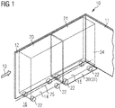
- Fig. 1 shows a receiving space 10 with two arranged one behind the other Supply containers 20 and 21 on two trolley parking spaces 14 and 15 arranged one behind the other.
- the vehicle in this exemplary embodiment is a commercial aircraft
- the rollable supply containers 20 and 21 are therefore designed as serving trolleys, so-called trolleys, according to the Atlas standard. These are so-called “full-size trolleys", i.e. serving trolleys with a full depth of approximately 80 cm.
- the receiving space 10 is usually fully closed and accessible via an insertion opening 13. It can be part of a galley, also known as a galley. To store the supply containers 20 and 21, they are pushed into the receiving space 10 via the insertion opening 13 (indicated by an arrow symbol).
- the rear trolley parking space 15 is provided in the receiving space 10 shown in such a way that the rear supply container 21 runs with its rear container wall 24 adjacent or adjacent to the rear wall 11 of the receiving space 10.
- the front trolley parking space 14 and the rear trolley parking space 15 are aligned along a common longitudinal axis 25.
- the front supply container 20 is thus positioned exactly in front of the rear supply container 21, so that the rear supply container 21 can only be removed from the storage position when the front supply container 20 has been removed and the front trolley parking space 14 is free. Access via the insertion opening 13 to the rear trolley parking space 14 is difficult or even impossible without aids due to the limited arm reach when handled by the flight attendants. Even if this arrangement of trolley parking spaces in a commercial aircraft is not preferred under the aspect of operability, structural constraints can, however, lead to an optimized use of space in the limited space of a commercial aircraft if such supply containers can also be arranged one behind the other.
- a stowage and Removal system 30 is provided for this parking space 15.
- This stowage and removal system 30 is installed in the floor area below the supply container 21.
- a transfer plate 31 is provided, which is designed to be pulled out and thus enables the supply container 21 to be loaded and removed in a position that is comfortable for the flight attendants.
- a detailed description of the stowage and removal system 30 is given below with reference to FIG Figures 2 to 5 .
- FIGs 2a and 2b In a perspective view of the supply container 21 on the trolley parking space 15, the stowage and removal system 30 according to the invention becomes somewhat clearer.
- the supply container 21 is shown in the storage position.
- the supply container 21 stands on a transfer plate 31 which is movably mounted on a rail system 32 and which can be moved in a removal direction 34.
- the rail system 32 is in the floor area of the receiving space 10 (see Fig. 1 ) fixed. In the case of training as a trolley parking space in a galley, this can be provided directly on the aircraft floor within the galley or also on the floor belonging to the receiving space 10.
- the transfer plate 31 has drive-on aids 33 in the front area, which enable the rollers 22 of the supply container 21 to be moved onto the transfer plate 31 or back down again.
- the rear rollers 22 of the supply container 21 can approach a stop 35 which defines the storage position and prevents the transfer plate 31 from rolling over.
- the Figure 2b shows the supply container 21 in the removal position.
- the transfer plate 31 is moved on the rail system 32 in the removal direction 34 up to the front end position and is at least partially positioned on the front trolley parking space 14.
- Front locking elements 37 shown in FIG Fig. 4
- front end stop 39 shown in FIG Fig. 4
- rear end stops 38 can be seen, which the transfer plate 31 in operative connection with rear locking elements 36 (shown later) in FIG Hold the storage position.
- the Figures 3a and 3b show the supply container 21 in a side view positioned on the transfer plate 31 in the storage position and the removal position.
- the rail system 32 is designed as a linear guide system, the guide rails of which are flat.
- the overall height of the rails is in a range from 5 to 20 mm. This ensures that the drive-on height onto the transfer plate 21 can be selected in such a way that the handling of normally fully loaded and thus heavy rollable supply containers via the drive-on aids 33 remains manageable.
- Fig. 3a the storage position is shown.
- the supply container 21 is positioned on the transfer plate 31 and the rear rollers 22 of the supply container 21 are attached to the rear stop 35 of the transfer plate 31 in order to ensure that the supply container 21 stands securely on the transfer plate 31.
- Figure 3b shows the supply container 21 in the removal position, ie the transfer plate 31 has been moved in the removal direction 34 by means of the rail system 32.
- rolling elements 41 are arranged in the front region of the transfer plate 31.
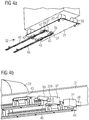
- FIGS Figures 4a and 4b Detailed views of the supply container 21 arranged on the stowage and removal system 30 in the removal position, as well as an advantageous embodiment of the rail system 32 and its mode of operation, are shown in FIGS Figures 4a and 4b shown.
- Figure 4a shows the rail system 32, which is arranged below the transfer plate 31, with a view from below.
- the moving bodies 42 running on guide rails 40 are fastened to the transfer plate 31.
- the guide rails 40 are preferably designed as linear guide rails, and telescopic rails can also be used.
- a lock can be attached to a front end stop 39, each attached to the corresponding guide rail 40 take place in the position of the transfer plate 31 in order to then safely allow a removal movement of the supply container 21 from the fixed transfer plate.
- FIG 4b the guide rails 40, the respective moving body elements 42 and the front lock 37 are shown in a detailed view.
- the front lock 37 for example provided with a snap lock 37A, is moved over the front end stop 39 in this extended position of the transfer plate 31 (entry and removal position of the supply container 21) and locks the transfer plate 31 for the loading and unloading process.
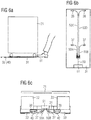
- FIG. 5 the rear stop 35 for the rollers 22 for positioning the supply container 21 is shown with a view of the rear of the supply container 21.
- the transfer plate 31 is in the foremost position of the rail system 32 on the guide rails 40. In this position, the transfer plate 31 can be moved, that is, from the shown extended position (removal position), the transport plate 31 can be supported by force, manually or supported by drives the supply container 21 are moved into the storage position.
- rear end stops 38 are provided, which interact with rear locks 36 of the transfer plate 31.
- FIGs 6a, 6b and 6c show the supply container 21 positioned on the transfer plate 31 in a side view, a view from below and in a view from the front in a detailed representation.
- the transfer plate 31 is equipped on the underside with an embodiment of front and rear locking devices 37 and 36, which are operated via at least one mechanical cable 50, preferably four cables 50A, 50B, 50C and 50D according to the embodiment shown.
- the cables 50 are preferably designed in the manner of Bowden cables and can be operated, for example, via a foot pedal 51 and thus the locks lock or unlock.
- An alternative actuation of the cables 50 can also be a lever element which can be operated by hand (not shown).
- Figures 7a and 7b show a second embodiment of an actuating and locking device.
- Figure 7a shows in a side view that the foot pedal 51 can be operated in order to release the lock.
- Figure 7b it is shown schematically that the foot pedal 51 can control the locking elements 37 'in the manner of an electromechanical actuation.
- Signal lines 52 can be used for this, but wireless controls can also take place.
- FIGS 8a and 8b show a third embodiment of a locking device with mechanical actuation in a schematic representation. It is provided here that a hand crank 53 engages in a lock element 54 and, by turning in the lock element 54, actuates the locking element 37 ′′ or several locking elements 37 ′′. With the use of the hand crank 53, after engaging or rotating in the lock element 54, a load / force can also be applied to the transfer plate 31 at the same time and the plate can thus also be moved.
- Fig. 9 shows another embodiment of a stowage and removal system.
- the receiving space 10 is shown with two trolley parking spaces 14 and 15 arranged one behind the other. These trolley parking spaces 14 and 15 are used to accommodate the rollable supply containers 20 and 21 (shown in FIG Figures 11A to 11C ).
- the receiving space 10 is usually fully closed and accessible via the insertion opening 13. To store the supply containers 20 and 21, they are pushed into the receiving space 10 via the insertion opening 13 (indicated by an arrow symbol).
- the rear trolley parking space 15 is provided in the receiving space 10 shown in such a way that the rear supply container 21 is positioned with its rear container wall 24 at a stop 18 adjacent or adjacent to the rear wall 11 of the receiving space 10.
- the front trolley parking space 14 and the rear trolley parking space 15 are aligned along a common longitudinal axis.
- the front supply container 20 is thus positioned exactly in front of the rear supply container 21, so that the rear supply container 21 can only be removed from the storage position when the front supply container 20 has been removed and the front trolley parking space 14 is free.
- a stowage and removal system 30A is provided for this parking space 15 according to the invention.
- This stowage and removal system 30A is arranged in the floor area. Essentially, a transfer plate 31A is provided, which can be moved on a rail system 32A.
- the transfer plate 31A can be moved on the rail system 32A as far as the insertion opening 13 and thus enable the supply container 21 to be loaded and removed at a position that is comfortable for the flight attendants.
- a detailed description of the stowage and removal system 30A is provided below with reference to FIG Figures 10 to 12 .
- FIG. 10a to 10c is the stowage and removal system 30A according to FIG Fig. 9 shown in different loading and parking positions.
- the transport rollers 22 of the supply containers 20 and 21 (not shown) are indicated in each case.
- the rail system 32A has guide rails 40A and 40B which are positioned in such a way that they each run approximately perpendicularly below the transport rollers 22.
- the term "approximately perpendicular" in this context means that they run in such a way that the guide rail 40A or 40B cannot be rolled over directly by the transport rollers 22, but they are arranged as close as possible to the load application points of the transport rollers 22.
- the transfer plate 31A or cover elements 45 serve as the running surface for the transport rollers 22 in the area of the upper side of the guide rails 40A or 40B.
- the respective guide rail 40A or 40B is preferably equipped as a guide rail 40 with two parallel longitudinal rails 40AA and 40AA 'and 40BB and 40BB', with a base body acting as a cover element 45 between the longitudinal rails 40AA and 40AA 'and 40BB and 40BB'.
- the transfer plate 31A is positioned in the area of the insertion opening.
- Drive-on aids 33 are fixed at the appropriate point in the floor area 16 in order to enable the supply container 21 to be driven onto the transfer plate 31A.
- the transfer plate 31A can now be moved to the rear parking space 15 with the supply container 21 positioned on it (see FIG Figure 10B ).
- the guide rails 40A and 40B which run into the area of the insertion opening 13 for moving the transfer plate 31A, are in this embodiment of the rail system in the area of the front parking space 14 with a cover 45 as a bearing and running body for the transport rollers 22 of the front supply container 20 provided.
- the cover element 45 is provided between the longitudinal rails 40AA and 40AA 'and 40BB and 40BB'.
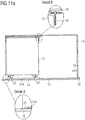
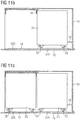
- FIGS 11a to 11c show the receiving space 10 according to Fig. 9 in different loading and parking positions of the two supply containers 20 and 21 arranged one behind the other.
- Figure 11A the entry and removal position of the supply container 21 can be seen.
- the supply container 21 is pushed onto the transfer plate 31A when it is retracted.
- the drive-on aid 33 is shown, which is necessary to overcome the height difference between the floor 16 and the transfer plate 31A.
- the drive-up aid can be designed beveled on one side or on both sides (as shown).
- Locking devices are provided for positioning and locking the transfer plate 31A. Such locking devices can be designed by way of example, as has already been described in detail for the first embodiment of the stowage and removal system (see FIG Figures 4 to 8 ) described.
- a locking element 19 is provided as a stop for moving the container 21 onto the transfer plate 31A.
- the locking element 19 is arranged in the ceiling area of the receiving space 10 and is rotated after the container 21 has been positioned in order to enable the transfer plate 31a to move to the rear parking space 15.
- the retraction of the container 21 on the rear wall of the receiving space 10 is limited by a stop 18.
- Figure 11B this position of the rear container 21 is shown.
- Figure 11C the receiving space 10 with the two containers 20 and 21 positioned one behind the other can be seen.
- the rear container 21 is mounted on the transfer plate 31A, the front container 20 stands with its rollers 22 on the bearing and running bodies 45.
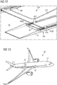
- Figure 12 is shown in a detailed view of the rail system 32A according to the second embodiment in the area of the front end of the guide rails 40A and 40B, which is designed for moving the containers 20 and 21 in and out.
- drive-on aids 33 are arranged at a corresponding position on the floor 16.
- Movement bodies 42A are provided on the transfer plate 31A, which are displaceable in the longitudinal rails are.
- the cover element or the flat body 46 is designed as an insert between the rails as a bearing and running body 46 for the transport rollers 22 of the front container 20.
- the height is adapted to the height of the running rails 40BB and 40BB '.
- a simple, yet very effective stowage and removal system can be implemented, which can significantly increase the compactness of a galley or other facilities, because a parking space with sufficient depth can be filled with several serving trolleys in a row without any restrictions that Due to the handling of a user of average height, having to be considerate.
- FIG. 13 an aircraft 60 with a fuselage 61 and a cabin 62 formed therein, in which a cabin monument 63 can be arranged, which has a receiving space 10 for supply containers and is equipped with a stowage and removal system 30 or 30A according to the invention.
Abstract
Es ist ein Verstau- und Entnahmesystem 30 für einen Aufnahmeraum 10 zur Lagerung für rollbare Behälter 20, 21 in einem Fahrzeug vorgesehen, Es weist vorzugsweise ein Schienensystem im Bodenbereich 16 des Aufnahmeraumes 10 auf, auf der eine Transferplatte 31 bewegbar ist und die eine Lagerposition sowie eine Einfahr- und Entnahmeposition für den Behälter 21 einnehmen kann. Die Lagerposition des Behälters 21 ist mit seiner Rückwand 23 im Bereich der Rückwand 11 des Aufnahmeraumes 10 vorgesehen. Die Einfahr- und Entnahmeposition ist im Bereich einer Einschuböffnung 13, gegenüberliegend zur Hinterwand 11, zum Einschieben und Entnehmen eines Behälters 21 in den Aufnahmeraum 10 vorgesehen. Insbesondere kann somit im Aufnahmeraum 10 einer Bordküche erreicht werden, dass hintereinander angeordnete Verpflegungsbehälter 20 und 21 in einem Aufnahmeraum 10 durch Bordpersonal leicht zu handhaben sind, so dass insbesondere der hinten angeordnete Verpflegungsbehälter 21 möglichst einfachA stowage and removal system 30 is provided for a receiving space 10 for storing rollable containers 20, 21 in a vehicle. It preferably has a rail system in the floor area 16 of the receiving space 10, on which a transfer plate 31 can be moved and which has a storage position as well can assume an entry and removal position for the container 21. The storage position of the container 21 is provided with its rear wall 23 in the area of the rear wall 11 of the receiving space 10. The entry and removal position is provided in the area of an insertion opening 13, opposite the rear wall 11, for inserting and removing a container 21 into the receiving space 10. In particular, it can thus be achieved in the receiving space 10 of an on-board kitchen that catering containers 20 and 21 arranged one behind the other in a receiving space 10 are easy to handle by on-board personnel, so that in particular the catering container 21 arranged at the rear is as simple as possible
Description
Die Erfindung betrifft ein Verstau- und Entnahmesystem für rollbare Behälter in einem Fahrzeug sowie ein Fahrzeug mit einem derartigen System.The invention relates to a stowage and removal system for rollable containers in a vehicle and to a vehicle with such a system.
Fahrzeuge, die dem Transport einer Vielzahl von Passagieren dienen, sind üblicherweise mit Kabinen mit Passagiersitzen, einer oder mehreren Bordtoiletten und optional einer oder mehreren Bordküchen ausgestattet. Insbesondere bei der Kompaktierung von Bordküchen in Verkehrsflugzeugen existieren Konzepte, bei denen Stellplätze für Servierwagen (Trolleys) genutzt werden, in denen mehrere Servierwagen hintereinander angeordnet werden. Üblicherweise bezieht sich dies auf die Verwendung von Servierwagen gemäß ATLAS-, ARINC- oder KSSU-Standards und die kombinierte Verwendung eines Servierwagens mit voller Bautiefe ("Full Size Trolley") und eines Servierwagens mit halber Bautiefe ("Half Size Trolley") oder zweier Servierwagen mit voller Bautiefe (zwei "Full Size Trolley"). Auch für Versorgungsbehälter, die als Boxen in der Bordküche gelagert werden müssen, kann aufgrund der Bautiefe für den Lagerraum eine Verstauung von zwei Boxen oder mehr hintereinander möglich sein.Vehicles that are used to transport a large number of passengers are usually equipped with cabins with passenger seats, one or more on-board toilets and optionally one or more on-board kitchens. Particularly when it comes to compacting galleys in commercial aircraft, there are concepts in which parking spaces for serving trolleys (trolleys) are used, in which several serving trolleys are arranged one behind the other. Usually this refers to the use of serving trolleys in accordance with ATLAS, ARINC or KSSU standards and the combined use of a serving trolley with full installation depth ("Full Size Trolley") and a serving trolley with half installation depth ("Half Size Trolley") or two full-depth serving trolleys (two "full size trolleys"). For supply containers that have to be stored as boxes in the galley, two or more boxes can be stowed one behind the other due to the depth of the storage space.
Zum Entnehmen von Servierwagen aus einem solchen Stellplatz wird üblicherweise ein an einer Oberseite befindlicher Griff durch einen Benutzer gegriffen und aus dem Stellplatz herausgezogen. Der Servierwagen ist dafür mit Rollen ausgestattet, die zum Verfahren innerhalb des Küchenbereichs sowie auch für den Servierprozess innerhalb der Flugzeugkabine zum Bewegen des Servierwagens im Flugzeuglängsgang von Sitzreihe zu Sitzreihe vorgesehen sind. Für Servierwagen auf den hinteren Stellplätzen ist notwendigerweise eine Entnahmevorrichtung vorgesehen. Insbesondere wenn ein Full-Size-Trolley in einem hinteren Stellplatz geparkt ist, ist es für die Flugbegleiter möglicherweise ein größerer Kraftaufwand und auch in der Zugänglichkeit erschwert, den Full-Size-Trolley aus dem hinteren Stellplatz heraus zu befördern.To remove serving trolleys from such a parking space, a handle located on an upper side is usually gripped by a user and pulled out of the parking space. The serving trolley is equipped with rollers for this purpose, which are provided for moving within the kitchen area as well as for the serving process within the aircraft cabin for moving the serving trolley in the longitudinal aisle of the aircraft from seat row to seat row. A removal device is necessarily provided for serving trolleys in the rear parking spaces. In particular, if a full-size trolley is parked in a rear parking space, the flight attendants may need more effort and accessibility to move the full-size trolley out of the rear parking space.
Derartige Entnahmeeinrichtungen für Servierwagen sind aus
Zur weiteren Kompaktierung von Bordküchen könnte es hilfreich sein,For further compacting on-board kitchens, it could be helpful
Verpflegungsbehälter, wie Servierwagen oder auch Boxen hintereinander in einem Aufnahmeraum anzuordnen. Dies ist jedoch in der Handhabbarkeit nicht optimal, denn ein hinterer Servierwagen oder eine hintere Box kann von Bordpersonal nur sehr schwer erreicht werden, da er sich in einem relativ großen Abstand von einer Einschuböffnung des Stellplatzes befindet.To arrange catering containers, such as serving trolleys or boxes, one behind the other in a receiving room. However, this is not optimal in terms of manageability, because a rear serving trolley or a rear box can only be reached with great difficulty by on-board personnel, since it is located at a relatively large distance from an insertion opening of the parking space.
Eine Aufgabe der Erfindung liegt folglich darin, eine Vorrichtung oder eine Bordküche vorzuschlagen, mit der hintereinander angeordneten Verpflegungsbehälter in einem Aufnahmeraum durch Bordpersonal leicht zu handhaben sind, so dass insbesondere in einem Aufnahmeraum hinten angeordnete Verpflegungsbehälter möglichst einfach erreichbar sind.One object of the invention is therefore to propose a device or a galley with which the catering containers arranged one behind the other in a receiving space can be easily handled by on-board personnel, so that in particular in a receiving space at the rear, catering containers can be reached as easily as possible.
Die Aufgabe wird gelöst durch ein Verstau- und Entnahmesystem für Verpflegungsbehälter in einem Fahrzeug mit den Merkmalen des unabhängigen Anspruchs 1. Vorteilhafte Ausführungsformen und Weiterbildungen sind den Unteransprüchen und der nachfolgenden Beschreibung zu entnehmen. Die Anwendung eines derartigen Verstau- und Entnahmesystems ist nicht auf Verpflegungsbehälter beschränkt, es können auch Behälter für andere Zwecke mit dem erfindungsgemäßen Verstau- und Entnahmesystem bewegt werden.The object is achieved by a stowage and removal system for food containers in a vehicle with the features of
Es wird ein Verstau- und Entnahmesystem für Behälter in einem Fahrzeug, vorgeschlagen, welches im Wesentlichen ein Schienensystem im Bodenbereich aufweist und einen Versorgungsbehälter von einer Lagerposition zu einer Entnahmeposition bewegen kann. Das System weist dafür ein Schienensystem im Bodenbereich des Aufnahmeraumes auf. Der Boden kann beispielsweise ein Bodenelement des Aufnahmeraumes sein oder aber auch ein Fahrzeugboden, in dem der Aufnahmeraum angeordnet ist. Das Schienensystem kann auf dem Boden befestigt sein oder auch im Fußboden integriert werden. Die Auswahl der entsprechenden Befestigung auf dem Boden oder Integration in den Boden erfolgt mit dem Ziel, die Gesamtaufbauhöhe des Schienensystems zu minimieren, um die baulichen Gegebenheiten des Aufnahmeraumes zu berücksichtigen, die auf die Abmessungen der entsprechenden Verpflegungsbehälter angepasst sind.A stowage and removal system for containers in a vehicle is proposed, which essentially has a rail system in the floor area and can move a supply container from a storage position to a removal position. For this purpose, the system has a rail system in the floor area of the receiving room. The floor can be, for example, a floor element of the receiving space or also a vehicle floor in which the receiving space is arranged. The rail system can be attached to the floor or integrated into the floor. The selection of the appropriate fastening on the floor or integration into the floor is made with the aim of minimizing the overall height of the rail system in order to reduce the the structural conditions of the reception room must be taken into account, which are adapted to the dimensions of the corresponding catering containers.
Weiterhin ist eine Transferplatte vorgesehen, die auf dem Schienensystem bewegbar ist und eine Lagerposition sowie eine Entnahmeposition für den Verpflegungsbehälter einnehmen kann. Die Lagerposition des Verpflegungsbehälters mit seiner Rückwand ist angrenzend an die Rückwand des Aufnahmeraumes vorgesehen. Die Entnahmeposition ist im Bereich einer Einschuböffnung zum Einschieben und Entnehmen eines Verpflegungsbehälters in den Aufnahmeraum vorgesehen. Diese Einschuböffnung ist gegenüberliegend zur Rückwand des Aufnahmeraumes ausgebildet.
Das Schienensystem weist Führungsschienen, vorzugsweise Linearsysteme oder auch Teleskopführungsschienen auf, die im Bereich der Lagerposition am Fußboden in Bewegungsrichtung der Transferplatte angeordnet sind. Die Linearsysteme können beispielsweise als Führungsschienen ausgebildet sein, die mit Bewegungskörpern wie Laufrollen oder mit Schienenkörpern aus Kugellagern oder Wälzkörpern korrespondieren. Auch Bewegungskörper als Gleitkörper sind einsetzbar. Beispielsweise sind Linerarführungen mit Kunststoffgleitlagern anwendbar. Derartige Bewegungskörper sind an der Transferplatte angeordnet.Furthermore, a transfer plate is provided which can be moved on the rail system and can assume a storage position as well as a removal position for the catering container. The storage position of the catering container with its rear wall is provided adjacent to the rear wall of the receiving space. The removal position is provided in the area of an insertion opening for inserting and removing a food container into the receiving space. This insertion opening is formed opposite to the rear wall of the receiving space.
The rail system has guide rails, preferably linear systems or telescopic guide rails, which are arranged in the area of the storage position on the floor in the direction of movement of the transfer plate. The linear systems can be designed, for example, as guide rails which correspond to moving bodies such as rollers or to rail bodies made of ball bearings or rolling bodies. Moving bodies can also be used as sliding bodies. For example, linear guides with plastic plain bearings can be used. Such moving bodies are arranged on the transfer plate.
In einer bevorzugten Ausführungsform ist der Aufnahmeraum zum Aufnehmen mindestens zwei hintereinander angeordneter Verpflegungsbehälter ausgebildet und der hintere Verpflegungsbehälter ist auf der Transferplatte positioniert.In a preferred embodiment, the receiving space is designed to receive at least two food containers arranged one behind the other and the rear food container is positioned on the transfer plate.
Der Aufnahmeraum ist folglich sehr bequem mit größeren, rollbaren Behältern befüllbar und erlaubt insbesondere bei der Verwendung in einer Kabine eines Verkehrsflugzeugs die sehr platzsparende, raumökonomische Unterbringung von Servierwagen hintereinander.The receiving space can consequently be filled very conveniently with larger, rollable containers and, especially when used in a cabin of a commercial aircraft, allows serving trolleys to be placed one behind the other in a very space-saving, space-saving manner.
Nach einer herkömmlichen Entnahme eines vorderen Behälters, der an derAfter a conventional removal of a front container attached to the
Einschuböffnung angeordnet ist, kann durch Verwendung eines Entnahme- und Verstausystems der hintere Behälter entnommen werden, der von der Einschuböffnung deutlich beabstandet im Innern des Aufnahmeraumes angeordnet ist.Insertion opening is arranged, the rear container can be removed by using a removal and stowage system, which is arranged at a significant distance from the insertion opening in the interior of the receiving space.
Für Versorgungsbehälter, beispielsweise Servierwagen, die auf den hinteren Stellplätzen einer Bordküche in einem Fahrzeug angeordnet sind, ist vorzugsweise das erfindungsgemäßes Verstau- und Entnahmesystem vorgesehen. Insbesondere wenn ein Full-Size-Trolley in einem hinteren Stellplatz geparkt ist, ist es für die Flugbegleiter eine große Erleichterung, den relativ schweren Behälter mittels der Transferplatte in einen gut erreichbaren Zugriffsbereich zu positionieren und in einfacher Weise aus dem hinteren Stellplatz heraus zu befördern.The storage and removal system according to the invention is preferably provided for supply containers, for example serving trolleys, which are arranged in the rear parking spaces of a galley in a vehicle. Especially when a full-size trolley is parked in a rear parking space, it is a great relief for the flight attendants to use the transfer plate to position the relatively heavy container in an easily accessible access area and to easily move it out of the rear parking space.
Die der Einschuböffnung gegenüberliegend angeordnete Rückwand des Aufnahmeraums ist eine hintere Begrenzung eines Stellplatzes in dem Aufnahmeraum, an die ein hinterster Behälter anstößt bzw. in Anschlag gerät bzw. angrenzt. Dies entspricht der Lagerposition des Versorgungsbehälters. Die Größe und Form des Behälters kann je nach Anforderung in dem Fahrzeug gewählt werden. Wird das Fahrzeug als ein Verkehrsflugzeug realisiert, bietet sich die Verwendung von Servierwagen nach einschlägigen Standards an, etwa nach dem ATLAS-Standard. Die erfindungsgemäßen Vorteile werden zudem dann besonders deutlich, wenn die rollbaren Behälter eine Tiefenerstreckung aufweisen, die größer als 30 bis 40 cm ist. Insbesondere bei einem Full-Size-Trolley, der ungefähr eine Länge von 80 bis 82 cm aufweist.The rear wall of the receiving space arranged opposite the insertion opening is a rear delimitation of a parking space in the receiving space, against which a rearmost container abuts or comes into abutment or is adjacent. This corresponds to the storage position of the supply container. The size and shape of the container can be selected depending on the requirements in the vehicle. If the vehicle is implemented as a commercial aircraft, the use of serving trolleys in accordance with relevant standards, such as the ATLAS standard, is recommended. The advantages according to the invention also become particularly clear when the rollable containers have a depth that is greater than 30 to 40 cm. In particular with a full-size trolley that is approximately 80 to 82 cm long.
Die Transferplatte ist mit mindestens eine Verriegelungsvorrichtung ausgestattet, die das Verriegeln der Transferplatte für die Einfahr- und Entnahmeposition realisiert. Es kann auch zusätzlich oder optional vorgesehen sein, in der Lagerposition, d,h, den an die Rückwand angrenzenden Behälter durch Fixierung der Transferplatte in seiner dortigen Stellung fixieren. Die Verriegelungsvorrichtung kann dafür Verriegelungselemente, vorzugsweise vordere und hintere Verriegelungselemente aufweisen. Diese können auf eine beliebige Weise ausgestaltet sein, die das einfache Verriegeln und das leichte Lösen zur Entnahme des betreffenden Behälters erlaubt. Das Verriegeln kann insbesondere durch ein bewegbares, formschlüssig wirkendes Riegelelement realisiert werden, das mit einem entsprechenden Formmerkmal des Behälters oder der Transferplatte korrespondiert.The transfer plate is equipped with at least one locking device which realizes the locking of the transfer plate for the entry and removal position. It can also be provided additionally or optionally, in the storage position, that is, the container adjacent to the rear wall by fixing the transfer plate in its fix there position. The locking device can have locking elements, preferably front and rear locking elements. These can be designed in any way that allows simple locking and easy release for removing the container in question. The locking can in particular be realized by a movable, form-fitting locking element which corresponds to a corresponding shape feature of the container or the transfer plate.
Die mindestens eine Verriegelungsvorrichtung kann vorzugsweise mechanisch oder elektromechanisch betätigbar sein. Auch eine selbsttätige Verriegelung und/oder Entriegelung ist denkbar. Beispielsweise bei Erreichen der Einfahr- und Entnahmeposition erfolgt eine selbsttätige Verriegelung der Transferplatte in dieser Position und für die Bewegung in die Lagerposition wird die Transferplatte aktiv entriegelt. Ein Bedienelement, welches mit der Verriegelungsvorrichtung verbunden ist, kann insbesondere an einer dem Benutzer zugewandten Seite angeordnet sein. Einem Benutzer wird hierdurch sehr leicht ermöglicht, die Verriegelungsvorrichtung zu lösen bzw. Kenntnis von dem momentanen Verriegelungszustand zu erlangen. Die konkrete Ausgestaltung des Bedienelements kann von der Art der Verriegelungsvorrichtung abhängen. Es bieten sich Zug-, Schub- und Drehelemente an, welche durch ein Gestänge oder eine andere Einrichtung eine gewünschte axiale, rotatorische oder kombinierte axiale und rotatorische Bewegung an die erste Verriegelungsvorrichtung weiterleiten.
Beispielsweise kann ein Fußpedal vorgesehen sein, welches über Seilzüge die entsprechenden Verriegelungselemente ansteuert. Alternativ kann über Signalleitungen oder auch drahtlos die Verriegelungsvorrichtung angesteuert und ausgelöst werden. In einer weiteren alternativen Ausführungsform kann eine Handkurbel in ein entsprechendes Schlosselement eingreifen und die Betätigung der Verriegelung auslösen. Zusätzlich ist es auch denkbar, mit der Kurbel die Transferplatte zu bewegen, indem Schub- oder Zugkraft auf die Transferplatte einwirkt.The at least one locking device can preferably be actuated mechanically or electromechanically. Automatic locking and / or unlocking is also conceivable. For example, when the entry and removal position is reached, the transfer plate is automatically locked in this position and the transfer plate is actively unlocked for movement into the storage position. An operating element that is connected to the locking device can in particular be arranged on a side facing the user. This makes it very easy for a user to release the locking device or to gain knowledge of the current locking state. The specific design of the operating element can depend on the type of locking device. There are pulling, pushing and rotating elements which convey a desired axial, rotary or combined axial and rotary movement to the first locking device by means of a linkage or some other device.
For example, a foot pedal can be provided which controls the corresponding locking elements via cables. Alternatively, the locking device can be controlled and triggered via signal lines or wirelessly. In a further alternative embodiment, a hand crank can engage in a corresponding lock element and trigger the actuation of the lock. In addition, it is also conceivable to move the transfer plate with the crank in that pushing or pulling force acts on the transfer plate.
Eine Kernkomponente des erfindungsgemäßen Verstau- und Entnahmesystems ist die Transferplatte, die den Verpflegungsbehälter aufnimmt und bewegt werden kann zwischen der Lagerposition und der Entnahmeposition. Um eine sichere Lagerung des Verpflegungsbehälters auf der Transferplatte zu ermöglichen, ist mindestens eine Positioniereinrichtung vorgesehen. Diese ist vorzugsweise als Anschlag im hinteren Bereich der Platte ausgebildet oder als Riegelelement an entsprechender Position im Aufnahmeraum.A core component of the stowage and removal system according to the invention is the transfer plate, which receives the catering container and can be moved between the storage position and the removal position. At least one positioning device is provided to enable safe storage of the catering container on the transfer plate. This is preferably designed as a stop in the rear area of the plate or as a locking element at a corresponding position in the receiving space.
Weiterhin kann das Verstau- und Entnahmesystem Auffahrhilfen aufweisen, die zur Überwindung des Höhenunterschieds zwischen Boden und der Transferplatte das Auffahren der rollbaren Verpflegungsbehälter erleichtert. Die Auffahrhilfen können auch an entsprechender Position am Fußboden vorgesehen sein, die dann in Wirkverbindung mit der an richtiger Stelle positionierten Transferplatte das Auffahren und Hinunterfahren der rollbaren Verpflegungsbehälters ermöglicht. Dies ist alternativ oder auch in Kombination zu den Auffahrhilfen an der Transferplatte möglich.
In einer vorteilhaften Ausgestaltung sind die Auffahrhilfen stirnseitig der Führungsschienen an entsprechender Position am Boden angeordnet.Furthermore, the stowage and removal system can have drive-on aids, which make it easier to drive up the rollable catering containers in order to overcome the height difference between the floor and the transfer plate. The drive-on aids can also be provided at a corresponding position on the floor, which then, in operative connection with the transfer plate positioned in the correct place, enables the rollable catering container to be driven up and down. This is possible as an alternative or in combination with the drive-up aids on the transfer plate.
In an advantageous embodiment, the drive-on aids are arranged on the front side of the guide rails at a corresponding position on the floor.
Das Schienensystem weist weiterhin vorzugsweise zwei parallel zu den Außenkanten der Transferplatte verlaufende Führungsschienen auf, die unterhalb der Transferplatte vorgesehen sind. Die Führungsschienen sind somit durch die Transferplatte in der Lagerposition abgedeckt.
Die Führungsschienen können derart positioniert sind, dass sie jeweils ungefähr lotrecht unterhalb der Transportrollen verlaufen und als Lauffläche für die Transportrollen im Bereich der Oberseite der Führungsschienen zumindest im Aufnahmeraum des vorderen Stellplatzes jeweils einem Abdeckelement vorgesehen ist.
In einer vorteilhaften Ausgestaltung ist die jeweilige Führungsschiene mit zwei parallel verlaufenden Längsschienen ausgestaltet, wobei zwischen den Längsschienen ein Lager-und Laufkörper als Abdeckelement und als Lauffläche für die Rollen wirkt. Damit ist ein Auffahren des vorderen Behälters mit seinen Transportrollen in den Aufnahmeraum im Bereich der Führungsschienen gewährleistet. Die Führungsschienen sind somit auch im vorderen Bereich des Aufnahmeraumes, vorzugsweise für den vorderen Stellplatz des Behälters, nicht störend und das Handhaben und Ein- und Ausfahren auch des vorderen Behälters ist trotz dort positionierter Schienen möglich.The rail system also preferably has two guide rails which run parallel to the outer edges of the transfer plate and are provided below the transfer plate. The guide rails are thus covered by the transfer plate in the storage position.
The guide rails can be positioned such that they each run approximately perpendicularly below the transport rollers and a cover element is provided as a running surface for the transport rollers in the area of the top of the guide rails, at least in the receiving space of the front parking space.
In an advantageous embodiment, the respective guide rail has two configured parallel longitudinal rails, with a bearing and running body acting as a cover element and as a running surface for the rollers between the longitudinal rails. This ensures that the front container with its transport rollers can be driven into the receiving space in the area of the guide rails. The guide rails are thus also not disruptive in the front area of the receiving space, preferably for the front storage space of the container, and the handling and moving in and out of the front container is possible despite the rails positioned there.
Mit anderen Worten können die Führungsschienen als Linearführungen ausgebildet sein, die jeweils mit einem Schienenelement und einem Bewegungskörper ausgestattet sind, wobei die Schienen auf dem Boden des Aufnahmeraumes oder dem Flugzeugboden fixiert sind und das jeweilige Bewegungselement an der Transferplatte angeordnet ist.In other words, the guide rails can be designed as linear guides that are each equipped with a rail element and a moving body, the rails being fixed on the floor of the receiving space or the aircraft floor and the respective moving element being arranged on the transfer plate.
Die Bewegung der Transferplatte ist aufgrund der Wahl von leichtlaufenden Schienen- bzw. Führungssystemen nur mit einer geringen Handhabungskraft möglich. Zur Bewegung der Transferplatte von der Entnahmeposition zur Lagerposition oder umgekehrt kann es somit ausreichen, dass durch ein Bedienelement das Bewegen der Transferplatte mittels Aktuatoren mit motorischer Unterstützung angesteuert wird. In einer möglichen Ausgestaltung könnte mit dem Bedienelement eine kabellose Ansteuerung der Aktuatoren zur Bewegung der Transferplatte sowie eine Statusanzeige über die Position der Transferplatte erfolgen. Ein manuelles Bewegen der Transferplatte kann alternativ ebenso in Erwägung gezogen werden, wenn nur geringe Handhabungskräfte notwendig sind und der Zugriffsbereich für eine Bedienperson ausreichend ist. Möglicherweise können auch Gestänge vorgesehen werden, die den Zugriff zur Transferplatte erleichtern und ggf. weiterhin die Betätigung der Verriegelungsvorrichtung vornehmen.The movement of the transfer plate is only possible with little handling force due to the choice of smooth-running rail or guide systems. In order to move the transfer plate from the removal position to the storage position or vice versa, it can thus be sufficient that the movement of the transfer plate is controlled by means of actuators with motor assistance by an operating element. In one possible embodiment, the operating element could be used to control the actuators for moving the transfer plate wirelessly and to display the status of the position of the transfer plate. Alternatively, manual movement of the transfer plate can also be considered if only low handling forces are required and the access area is sufficient for an operator. Possibly rods can also be provided that facilitate access to the transfer plate and, if necessary, continue to operate the locking device.
Die Erfindung betrifft ferner ein Fahrzeug mit einer Kabine und einem darin befindlichen Kabinenmonument, das ein Verstau- und Entnahmesystem gemäß der vorhergehenden Beschreibung aufweist.The invention also relates to a vehicle with a cabin and one therein located cabin monument, which has a stowage and removal system as described above.
Weitere Merkmale, Vorteile und Anwendungsmöglichkeiten der vorliegenden Erfindung ergeben sich aus der nachfolgenden Beschreibung der Ausführungsbeispiele und den Figuren. Dabei bilden alle beschriebenen und/oder bildlich dargestellten Merkmale für sich und in beliebiger Kombination den Gegenstand der Erfindung auch unabhängig von ihrer Zusammensetzung in den einzelnen Ansprüchen oder deren Rückbezügen. In den Figuren stehen weiterhin gleiche Bezugszeichen für gleiche oder ähnliche Objekte.
-
Fig. 1 zeigt eine räumliche Darstellung eines Aufnahmeraumes mit zwei hintereinander angeordneten Versorgungsbehältern auf zwei hintereinander angeordneten Trolleystellplätzen. -
Fig. 2a und Fig. 2b zeigen die Versorgungsbehälter auf dem Trolleystellplatz mit einem erfindungsgemäßen Verstau- und Entnahmesystem, -
Fig. 3a und 3b zeigen den Versorgungsbehälter auf einer Transferplatte in einer Ansicht von der Seite in Lagerposition und in Entnahmeposition. -
Fig. 4a und 4b zeigen in Detailansichten den Versorgungsbehälter angeordnet auf dem Verstau- und Entnahmesystem in Entnahmeposition. -
Fig. 5 zeigt den Versorgungsbehälter mit der hinteren Verriegelungsvorrichtung. -
Fig. 6a und 6b zeigen eine erste Ausführungsform einer Verriegelungsvorrichtung mit mechanischer Seilzugbetätigung. -
Fig. 7a und 7b zeigen eine zweite Ausführungsform einer Verriegelungsvorrichtung mit elektromechanischer Betätigung. -
Fig. 8a und 8b zeigen eine dritte Ausführungsform einer Verriegelungsvorrichtung mit mechanischer Betätigung. -
Fig. 9 zeigt den Aufnahmeraum mit einem erfindungsgemäßen Verstau- und Entnahmesystem in einer weiteren Ausführungsform. -
Fig. 10a bis 10c zeigen das Verstau-und Entnahmesystem gemäßFig. 9 in unterschiedlichen Belade- und Parkpositionen. -
Fig. 11a bis 11c zeigen den Aufnahmeraum gemäßFig. 9 in unterschiedlichen Belade- und Parkpositionen. -
Fig. 12 zeigt in einer Detailansicht das Schienensystem gemäß der zweiten Ausführungsform. -
Fig. 13 zeigt ein Flugzeug mit einer Kabine, in der eine Bordküche mit einem Aufnahmeraum angeordnet ist, ausgestattet mit einem erfindungsgemäßen Verstau-und Entnahmesystem.
-
Fig. 1 shows a three-dimensional representation of a receiving space with two supply containers arranged one behind the other on two trolley parking spaces arranged one behind the other. -
Figures 2a and 2b show the supply containers on the trolley parking space with a stowage and removal system according to the invention, -
Figures 3a and 3b show the supply container on a transfer plate in a view from the side in the storage position and in the removal position. -
Figures 4a and 4b show in detail views the supply container arranged on the stowage and removal system in the removal position. -
Fig. 5 shows the supply container with the rear locking device. -
Figures 6a and 6b show a first embodiment of a locking device with mechanical cable actuation. -
Figures 7a and 7b show a second embodiment of a locking device with electromechanical actuation. -
Figures 8a and 8b show a third embodiment of a locking device with mechanical actuation. -
Fig. 9 shows the receiving space with a stowage and removal system according to the invention in a further embodiment. -
Figures 10a to 10c show the stowage and removal system according to FIGFig. 9 in different loading and parking positions. -
Figures 11a to 11c show the recording space according toFig. 9 in different loading and parking positions. -
Fig. 12 shows the rail system according to the second embodiment in a detailed view. -
Fig. 13 shows an aircraft with a cabin in which a galley with an accommodation space is arranged, equipped with a stowage and removal system according to the invention.
Um die Entnahme oder auch das Abstellen des Versorgungsbehälters 21 auf dem hinteren Stellplatz 15 zu ermöglichen, ist erfindungsgemäß ein Verstau- und Entnahmesystem 30 für diesen Stellplatz 15 vorgesehen. Dieses Verstau- und Entnahmesystem 30 ist im Bodenbereich, unterhalb des Versorgungsbehälters 21 installiert. Im Wesentlichen ist eine Transferplatte 31 vorgesehen, die herausziehbar gestaltet ist und somit das Beladen und Entnehmen des Versorgungsbehälters 21 an einer für die Flugbegleiter komfortablen Position ermöglicht. Eine detaillierte Beschreibung des Verstau- und Entnahmesystems 30 erfolgt nachfolgend anhand der
In
Die
Detailansichten des Versorgungsbehälters 21 angeordnet auf dem Verstau- und Entnahmesystem 30 in Entnahmeposition sowie eine vorteilhafte Ausgestaltung des Schienensystems 32 und deren Funktionsweise sind in den
In
In
In
Um die Entnahme oder auch das Abstellen des Versorgungsbehälters 21 auf dem hinteren Stellplatz 15 zu ermöglichen, ist erfindungsgemäß ein Verstau- und Entnahmesystem 30A für diesen Stellplatz 15 vorgesehen. Dieses Verstau- und Entnahmesystem 30A ist im Bodenbereich angeordnet. Im Wesentlichen ist eine Transferplatte 31A vorgesehen, die auf einem Schienensystem 32A bewegbar ist. Die Transferplatte 31A kann auf dem Schienensystem 32A bis zur Einschuböffnung 13 bewegt werden und somit das Beladen und Entnehmen des Versorgungsbehälters 21 an einer für die Flugbegleiter komfortablen Position ermöglichen. Eine detaillierte Beschreibung des Verstau- und Entnahmesystems 30A erfolgt nachfolgend anhand der
In order to enable the
In den
Bevorzugt ist die jeweilige Führungsschiene 40A oder 40B als Führungsschiene 40 mit zwei parallel verlaufende Längs schienen 40AA und 40AA' und 40BB sowie 40BB' ausgestattet, wobei zwischen den Längsschienen 40AA und 40AA' und 40BB sowie 40BB' jeweils ein Basiskörper als Abdeckelement 45 wirkt. In
The
Die
In
Durch die gezeigten Komponenten kann folglich ein einfaches, dennoch sehr wirkungsvolles Verstau- und Entnahmesystem realisiert werden, das die Kompaktheit einer Bordküche oder anderen Einrichtungen deutlich vergrößern kann, denn ein Stellplatz mit ausreichender Tiefe kann mit mehreren Servierwagen hintereinander befüllt werden, ohne auf Beschränkungen, die sich durch die Handhabung eines Benutzers mit durchschnittlicher Körpergröße ergeben, Rücksicht nehmen zu müssen.With the components shown, a simple, yet very effective stowage and removal system can be implemented, which can significantly increase the compactness of a galley or other facilities, because a parking space with sufficient depth can be filled with several serving trolleys in a row without any restrictions that Due to the handling of a user of average height, having to be considerate.
Schließlich zeigt
Ergänzend sei darauf hingewiesen, dass "aufweisend" keine anderen Elemente oder Schritte ausschließt und "ein" oder "eine" keine Vielzahl ausschließt. Ferner sei darauf hingewiesen, dass Merkmale, die mit Verweis auf eines der obigen Ausführungsbeispiele beschrieben worden sind, auch in Kombination mit anderen Merkmalen anderer oben beschriebener Ausführungsbeispiele verwendet werden können. Bezugszeichen in den Ansprüchen sind nicht als Einschränkung anzusehen.In addition, it should be pointed out that “having” does not exclude any other elements or steps and “a” or “an” does not exclude a plurality. It should also be pointed out that features that have been described with reference to one of the above exemplary embodiments can also be used in combination with other features of other exemplary embodiments described above. Reference signs in the claims are not to be regarded as a restriction.
Claims (9)
wobei der Aufnahmeraum (10) zum Aufnehmen mindestens zwei hintereinander angeordneter Behälter (20, 21) mit einem vorderen Stellplatz (14) und einem hinteren Stellplatz (15) ausgebildet ist, wobei der hintere Behälter (21) auf der Transferplatte (31, 31A) positioniert ist.System (30) according to claim 1,
wherein the receiving space (10) is designed for receiving at least two containers (20, 21) arranged one behind the other with a front parking space (14) and a rear parking space (15), the rear container (21) on the transfer plate (31, 31A) is positioned.
wobei die Transferplatte (31) mindestens eine Verriegelungsvorrichtung (36, 37) zum lösbaren Verriegeln der Transferplatte (31) für die Entnahmeposition aufweist.System (30) according to one of Claims 1 to 3,
wherein the transfer plate (31) has at least one locking device (36, 37) for releasably locking the transfer plate (31) for the removal position.
ferner aufweisend mindestens eine Positioniereinrichtung (Anschlag 35, 19) des Behälters (21) auf der Transferplatte (31).System (30) according to one of claims 1 to 5,
furthermore having at least one positioning device (stop 35, 19) of the container (21) on the transfer plate (31).
wobei stirnseitig der Führungsschienen (40A, 40B) an entsprechender Position am Boden (16) Auffahrhilfen (33) auf die Transferplatte (31) oder den Abdeckelementen (45) für Behälter (21) angeordnet sind.System (30) according to one of Claims 1 to 6,
wherein at the end of the guide rails (40A, 40B) at a corresponding position on the floor (16), drive-on aids (33) are arranged on the transfer plate (31) or the cover elements (45) for containers (21).
wobei die Führungsschiene (40A, 40B) zwei parallel verlaufende Längsschienen (40AA, 40AA', 40BB, 40BB') aufweist, wobei zwischen den Längsschienen (40A, 40B) ein Lager-und Laufkörper (46) als Abdeckelement wirkt.System (30) according to one of Claims 1 to 7,
the guide rail (40A, 40B) having two parallel longitudinal rails (40AA, 40AA ', 40BB, 40BB'), a bearing and running body (46) acting as a cover element between the longitudinal rails (40A, 40B).
Applications Claiming Priority (1)
| Application Number | Priority Date | Filing Date | Title |
|---|---|---|---|
| DE102019108747.3A DE102019108747A1 (en) | 2019-04-03 | 2019-04-03 | Stowage and removal system for rollable containers in a vehicle and a vehicle with such a system |
Publications (2)
| Publication Number | Publication Date |
|---|---|
| EP3718889A1 true EP3718889A1 (en) | 2020-10-07 |
| EP3718889B1 EP3718889B1 (en) | 2022-09-07 |
Family
ID=70165850
Family Applications (1)
| Application Number | Title | Priority Date | Filing Date |
|---|---|---|---|
| EP20167761.4A Active EP3718889B1 (en) | 2019-04-03 | 2020-04-02 | Storage and retrieval system for rollable container in a vehicle and vehicle comprising such a system |
Country Status (3)
| Country | Link |
|---|---|
| US (1) | US11518518B2 (en) |
| EP (1) | EP3718889B1 (en) |
| DE (1) | DE102019108747A1 (en) |
Families Citing this family (1)
| Publication number | Priority date | Publication date | Assignee | Title |
|---|---|---|---|---|
| DE102019123107A1 (en) * | 2019-08-28 | 2021-03-04 | Airbus Operations Gmbh | Handling system for containers in a vehicle and a vehicle with such a system |
Citations (7)
| Publication number | Priority date | Publication date | Assignee | Title |
|---|---|---|---|---|
| US20080136299A1 (en) * | 2006-12-07 | 2008-06-12 | Be Aerospace, Inc. | Galley unit with cart lift for elevated cart storage |
| WO2008091287A2 (en) * | 2006-08-22 | 2008-07-31 | The Boeing Company | Cargo transport system and method |
| DE202008012692U1 (en) * | 2008-09-24 | 2009-03-19 | Bernhardi, Daniel | Device for preventing damage to man and material in aircraft by the in-flight trolley in case of turbulence |
| FR2954276A1 (en) * | 2009-12-17 | 2011-06-24 | Airbus | DEVICE FOR THE OPTIMIZED STORAGE OF TROLLEYS |
| WO2014125046A1 (en) | 2013-02-13 | 2014-08-21 | Sell Gmbh | Aircraft |
| DE102013006145A1 (en) * | 2013-04-10 | 2014-10-16 | Diehl Service Modules Gmbh | Cabin monument and aircraft cabin |
| WO2016034531A1 (en) | 2014-09-05 | 2016-03-10 | Sell Gmbh | Trolley arrangement of a galley of a vehicle, especially of an aircraft |
Family Cites Families (8)
| Publication number | Priority date | Publication date | Assignee | Title |
|---|---|---|---|---|
| US5322244A (en) * | 1992-03-17 | 1994-06-21 | Deutsche Aerospace Airbus Gmbh | Supply system for passenger aircraft |
| US5465660A (en) * | 1994-02-16 | 1995-11-14 | Aero-Design Technology | Aircraft trash collection and compacting apparatus |
| US6454208B1 (en) * | 2000-12-22 | 2002-09-24 | The Boeing Company | Automated galley-cart storage system |
| DE102006023047B4 (en) * | 2006-05-17 | 2010-01-14 | Airbus Deutschland Gmbh | Modular galley, especially for an aircraft |
| NL1034054C2 (en) * | 2007-06-28 | 2008-12-30 | Aerocat B V | Trolley. |
| FR2999546B1 (en) * | 2012-12-14 | 2016-10-14 | Airbus Operations Sas | FURNITURE FOR AIRCRAFT COMPRISING MEANS FOR DISPENSING A CARRIAGE BETWEEN TWO PARTS |
| DE102017128345A1 (en) * | 2017-11-29 | 2019-05-29 | Airbus Operations Gmbh | Aircraft galley |
| US20200339262A1 (en) * | 2019-04-29 | 2020-10-29 | B/E Aerospace, Inc. | Galley Cart Wheel Track |
-
2019
- 2019-04-03 DE DE102019108747.3A patent/DE102019108747A1/en active Pending
-
2020
- 2020-04-02 EP EP20167761.4A patent/EP3718889B1/en active Active
- 2020-04-02 US US16/838,325 patent/US11518518B2/en active Active
Patent Citations (7)
| Publication number | Priority date | Publication date | Assignee | Title |
|---|---|---|---|---|
| WO2008091287A2 (en) * | 2006-08-22 | 2008-07-31 | The Boeing Company | Cargo transport system and method |
| US20080136299A1 (en) * | 2006-12-07 | 2008-06-12 | Be Aerospace, Inc. | Galley unit with cart lift for elevated cart storage |
| DE202008012692U1 (en) * | 2008-09-24 | 2009-03-19 | Bernhardi, Daniel | Device for preventing damage to man and material in aircraft by the in-flight trolley in case of turbulence |
| FR2954276A1 (en) * | 2009-12-17 | 2011-06-24 | Airbus | DEVICE FOR THE OPTIMIZED STORAGE OF TROLLEYS |
| WO2014125046A1 (en) | 2013-02-13 | 2014-08-21 | Sell Gmbh | Aircraft |
| DE102013006145A1 (en) * | 2013-04-10 | 2014-10-16 | Diehl Service Modules Gmbh | Cabin monument and aircraft cabin |
| WO2016034531A1 (en) | 2014-09-05 | 2016-03-10 | Sell Gmbh | Trolley arrangement of a galley of a vehicle, especially of an aircraft |
Also Published As
| Publication number | Publication date |
|---|---|
| US11518518B2 (en) | 2022-12-06 |
| DE102019108747A1 (en) | 2020-10-08 |
| US20200317345A1 (en) | 2020-10-08 |
| EP3718889B1 (en) | 2022-09-07 |
Similar Documents
| Publication | Publication Date | Title |
|---|---|---|
| EP3718888B1 (en) | Receiving system for rollable containers in a vehicle and vehicle comprising such a system | |
| EP2440457B1 (en) | System and method for producing a vehicle cabin | |
| EP2358593B1 (en) | Device for fixing an object to a rail | |
| EP2416999B1 (en) | Transport cart that can be stored in a space-saving manner for equipping an aircraft galley | |
| EP2853446B1 (en) | Loading space cover | |
| DE202012013603U1 (en) | Modular cabin segment, cab for a vehicle and vehicle with a cab | |
| DE3245986A1 (en) | CATERING FACILITIES IN AN AIRPLANE WITH STORAGE CARS ARRANGED ON TWO DECKS | |
| DE2162042A1 (en) | Loading and unloading devices for aircraft | |
| DE102017117293A1 (en) | Stowage and removal system for rollable containers in a vehicle and a vehicle, in particular a commercial aircraft with such a system | |
| EP1396382B1 (en) | Load comparatment cover for vehicles, in particular for station wagons | |
| DE102021115039A1 (en) | MOTOR VEHICLE WITH TELESCOPIC REAR DOOR | |
| DE102018008316A1 (en) | Trolley for a passenger cabin | |
| EP3718889B1 (en) | Storage and retrieval system for rollable container in a vehicle and vehicle comprising such a system | |
| DE3127019C2 (en) | "Device for a reach mast-lift truck with a battery trolley held longitudinally movable in the direction of the vehicle" | |
| EP4021804B1 (en) | Handling system for containers in a vehicle and vehicle comprising such a system | |
| EP3718890B1 (en) | Storage and retrieval system for container in a vehicle and vehicle comprising such a system | |
| EP2370302A1 (en) | Transport cart for loading an aircraft galley | |
| DE102007009500B4 (en) | Mobile cladding for an aircraft roll container | |
| DE102019121933A1 (en) | Storage and removal system for containers in a vehicle and a vehicle with such a system | |
| DE102016103825A1 (en) | Arrangement in a vehicle cabin with a cabin monument with two access openings on two aisles forming a cut surface | |
| DE102015102025B4 (en) | tonneau cover | |
| AT16657U1 (en) | Trolley case | |
| DE102016109722A1 (en) | Arrangement for locking a serving trolley in a cabin of a means of transport on demand | |
| DE102015113450A1 (en) | Fillable storage container for placement in an aircraft | |
| DE102004036773B4 (en) | Device for fastening loading modules in a loading space |
Legal Events
| Date | Code | Title | Description |
|---|---|---|---|
| PUAI | Public reference made under article 153(3) epc to a published international application that has entered the european phase |
Free format text: ORIGINAL CODE: 0009012 |
|
| STAA | Information on the status of an ep patent application or granted ep patent |
Free format text: STATUS: THE APPLICATION HAS BEEN PUBLISHED |
|
| AK | Designated contracting states |
Kind code of ref document: A1 Designated state(s): AL AT BE BG CH CY CZ DE DK EE ES FI FR GB GR HR HU IE IS IT LI LT LU LV MC MK MT NL NO PL PT RO RS SE SI SK SM TR |
|
| AX | Request for extension of the european patent |
Extension state: BA ME |
|
| STAA | Information on the status of an ep patent application or granted ep patent |
Free format text: STATUS: REQUEST FOR EXAMINATION WAS MADE |
|
| 17P | Request for examination filed |
Effective date: 20210407 |
|
| RBV | Designated contracting states (corrected) |
Designated state(s): AL AT BE BG CH CY CZ DE DK EE ES FI FR GB GR HR HU IE IS IT LI LT LU LV MC MK MT NL NO PL PT RO RS SE SI SK SM TR |
|
| GRAP | Despatch of communication of intention to grant a patent |
Free format text: ORIGINAL CODE: EPIDOSNIGR1 |
|
| STAA | Information on the status of an ep patent application or granted ep patent |
Free format text: STATUS: GRANT OF PATENT IS INTENDED |
|
| INTG | Intention to grant announced |
Effective date: 20220407 |
|
| GRAS | Grant fee paid |
Free format text: ORIGINAL CODE: EPIDOSNIGR3 |
|
| GRAA | (expected) grant |
Free format text: ORIGINAL CODE: 0009210 |
|
| STAA | Information on the status of an ep patent application or granted ep patent |
Free format text: STATUS: THE PATENT HAS BEEN GRANTED |
|
| AK | Designated contracting states |
Kind code of ref document: B1 Designated state(s): AL AT BE BG CH CY CZ DE DK EE ES FI FR GB GR HR HU IE IS IT LI LT LU LV MC MK MT NL NO PL PT RO RS SE SI SK SM TR |
|
| REG | Reference to a national code |
Ref country code: GB Ref legal event code: FG4D Free format text: NOT ENGLISH |
|
| REG | Reference to a national code |
Ref country code: CH Ref legal event code: EP Ref country code: AT Ref legal event code: REF Ref document number: 1516864 Country of ref document: AT Kind code of ref document: T Effective date: 20220915 |
|
| REG | Reference to a national code |
Ref country code: DE Ref legal event code: R096 Ref document number: 502020001638 Country of ref document: DE |
|
| REG | Reference to a national code |
Ref country code: IE Ref legal event code: FG4D Free format text: LANGUAGE OF EP DOCUMENT: GERMAN |
|
| REG | Reference to a national code |
Ref country code: LT Ref legal event code: MG9D |
|
| REG | Reference to a national code |
Ref country code: NL Ref legal event code: MP Effective date: 20220907 |
|
| PG25 | Lapsed in a contracting state [announced via postgrant information from national office to epo] |
Ref country code: SE Free format text: LAPSE BECAUSE OF FAILURE TO SUBMIT A TRANSLATION OF THE DESCRIPTION OR TO PAY THE FEE WITHIN THE PRESCRIBED TIME-LIMIT Effective date: 20220907 Ref country code: RS Free format text: LAPSE BECAUSE OF FAILURE TO SUBMIT A TRANSLATION OF THE DESCRIPTION OR TO PAY THE FEE WITHIN THE PRESCRIBED TIME-LIMIT Effective date: 20220907 Ref country code: NO Free format text: LAPSE BECAUSE OF FAILURE TO SUBMIT A TRANSLATION OF THE DESCRIPTION OR TO PAY THE FEE WITHIN THE PRESCRIBED TIME-LIMIT Effective date: 20221207 Ref country code: LV Free format text: LAPSE BECAUSE OF FAILURE TO SUBMIT A TRANSLATION OF THE DESCRIPTION OR TO PAY THE FEE WITHIN THE PRESCRIBED TIME-LIMIT Effective date: 20220907 Ref country code: LT Free format text: LAPSE BECAUSE OF FAILURE TO SUBMIT A TRANSLATION OF THE DESCRIPTION OR TO PAY THE FEE WITHIN THE PRESCRIBED TIME-LIMIT Effective date: 20220907 Ref country code: FI Free format text: LAPSE BECAUSE OF FAILURE TO SUBMIT A TRANSLATION OF THE DESCRIPTION OR TO PAY THE FEE WITHIN THE PRESCRIBED TIME-LIMIT Effective date: 20220907 |
|
| PG25 | Lapsed in a contracting state [announced via postgrant information from national office to epo] |
Ref country code: HR Free format text: LAPSE BECAUSE OF FAILURE TO SUBMIT A TRANSLATION OF THE DESCRIPTION OR TO PAY THE FEE WITHIN THE PRESCRIBED TIME-LIMIT Effective date: 20220907 Ref country code: GR Free format text: LAPSE BECAUSE OF FAILURE TO SUBMIT A TRANSLATION OF THE DESCRIPTION OR TO PAY THE FEE WITHIN THE PRESCRIBED TIME-LIMIT Effective date: 20221208 |
|
| PG25 | Lapsed in a contracting state [announced via postgrant information from national office to epo] |
Ref country code: SM Free format text: LAPSE BECAUSE OF FAILURE TO SUBMIT A TRANSLATION OF THE DESCRIPTION OR TO PAY THE FEE WITHIN THE PRESCRIBED TIME-LIMIT Effective date: 20220907 Ref country code: RO Free format text: LAPSE BECAUSE OF FAILURE TO SUBMIT A TRANSLATION OF THE DESCRIPTION OR TO PAY THE FEE WITHIN THE PRESCRIBED TIME-LIMIT Effective date: 20220907 Ref country code: PT Free format text: LAPSE BECAUSE OF FAILURE TO SUBMIT A TRANSLATION OF THE DESCRIPTION OR TO PAY THE FEE WITHIN THE PRESCRIBED TIME-LIMIT Effective date: 20230109 Ref country code: ES Free format text: LAPSE BECAUSE OF FAILURE TO SUBMIT A TRANSLATION OF THE DESCRIPTION OR TO PAY THE FEE WITHIN THE PRESCRIBED TIME-LIMIT Effective date: 20220907 Ref country code: CZ Free format text: LAPSE BECAUSE OF FAILURE TO SUBMIT A TRANSLATION OF THE DESCRIPTION OR TO PAY THE FEE WITHIN THE PRESCRIBED TIME-LIMIT Effective date: 20220907 |
|
| PG25 | Lapsed in a contracting state [announced via postgrant information from national office to epo] |
Ref country code: SK Free format text: LAPSE BECAUSE OF FAILURE TO SUBMIT A TRANSLATION OF THE DESCRIPTION OR TO PAY THE FEE WITHIN THE PRESCRIBED TIME-LIMIT Effective date: 20220907 Ref country code: PL Free format text: LAPSE BECAUSE OF FAILURE TO SUBMIT A TRANSLATION OF THE DESCRIPTION OR TO PAY THE FEE WITHIN THE PRESCRIBED TIME-LIMIT Effective date: 20220907 Ref country code: IS Free format text: LAPSE BECAUSE OF FAILURE TO SUBMIT A TRANSLATION OF THE DESCRIPTION OR TO PAY THE FEE WITHIN THE PRESCRIBED TIME-LIMIT Effective date: 20230107 Ref country code: EE Free format text: LAPSE BECAUSE OF FAILURE TO SUBMIT A TRANSLATION OF THE DESCRIPTION OR TO PAY THE FEE WITHIN THE PRESCRIBED TIME-LIMIT Effective date: 20220907 |
|
| REG | Reference to a national code |
Ref country code: DE Ref legal event code: R097 Ref document number: 502020001638 Country of ref document: DE |
|
| PG25 | Lapsed in a contracting state [announced via postgrant information from national office to epo] |
Ref country code: NL Free format text: LAPSE BECAUSE OF FAILURE TO SUBMIT A TRANSLATION OF THE DESCRIPTION OR TO PAY THE FEE WITHIN THE PRESCRIBED TIME-LIMIT Effective date: 20220907 Ref country code: AL Free format text: LAPSE BECAUSE OF FAILURE TO SUBMIT A TRANSLATION OF THE DESCRIPTION OR TO PAY THE FEE WITHIN THE PRESCRIBED TIME-LIMIT Effective date: 20220907 |
|
| PLBE | No opposition filed within time limit |
Free format text: ORIGINAL CODE: 0009261 |
|
| STAA | Information on the status of an ep patent application or granted ep patent |
Free format text: STATUS: NO OPPOSITION FILED WITHIN TIME LIMIT |
|
| PG25 | Lapsed in a contracting state [announced via postgrant information from national office to epo] |
Ref country code: DK Free format text: LAPSE BECAUSE OF FAILURE TO SUBMIT A TRANSLATION OF THE DESCRIPTION OR TO PAY THE FEE WITHIN THE PRESCRIBED TIME-LIMIT Effective date: 20220907 |
|
| PGFP | Annual fee paid to national office [announced via postgrant information from national office to epo] |
Ref country code: FR Payment date: 20230424 Year of fee payment: 4 Ref country code: DE Payment date: 20230420 Year of fee payment: 4 |
|
| 26N | No opposition filed |
Effective date: 20230608 |
|
| PG25 | Lapsed in a contracting state [announced via postgrant information from national office to epo] |
Ref country code: SI Free format text: LAPSE BECAUSE OF FAILURE TO SUBMIT A TRANSLATION OF THE DESCRIPTION OR TO PAY THE FEE WITHIN THE PRESCRIBED TIME-LIMIT Effective date: 20220907 |
|
| REG | Reference to a national code |
Ref country code: CH Ref legal event code: PL |
|
| PG25 | Lapsed in a contracting state [announced via postgrant information from national office to epo] |
Ref country code: LU Free format text: LAPSE BECAUSE OF NON-PAYMENT OF DUE FEES Effective date: 20230402 |
|
| REG | Reference to a national code |
Ref country code: BE Ref legal event code: MM Effective date: 20230430 |
|
| PG25 | Lapsed in a contracting state [announced via postgrant information from national office to epo] |
Ref country code: MC Free format text: LAPSE BECAUSE OF FAILURE TO SUBMIT A TRANSLATION OF THE DESCRIPTION OR TO PAY THE FEE WITHIN THE PRESCRIBED TIME-LIMIT Effective date: 20220907 |
|
| PG25 | Lapsed in a contracting state [announced via postgrant information from national office to epo] |
Ref country code: MC Free format text: LAPSE BECAUSE OF FAILURE TO SUBMIT A TRANSLATION OF THE DESCRIPTION OR TO PAY THE FEE WITHIN THE PRESCRIBED TIME-LIMIT Effective date: 20220907 Ref country code: LI Free format text: LAPSE BECAUSE OF NON-PAYMENT OF DUE FEES Effective date: 20230430 Ref country code: CH Free format text: LAPSE BECAUSE OF NON-PAYMENT OF DUE FEES Effective date: 20230430 |
|
| REG | Reference to a national code |
Ref country code: IE Ref legal event code: MM4A |
|
| PG25 | Lapsed in a contracting state [announced via postgrant information from national office to epo] |
Ref country code: BE Free format text: LAPSE BECAUSE OF NON-PAYMENT OF DUE FEES Effective date: 20230430 |
|
| PG25 | Lapsed in a contracting state [announced via postgrant information from national office to epo] |
Ref country code: IE Free format text: LAPSE BECAUSE OF NON-PAYMENT OF DUE FEES Effective date: 20230402 |