EP3718877A1 - A joint for an aircraft assembly - Google Patents
A joint for an aircraft assembly Download PDFInfo
- Publication number
- EP3718877A1 EP3718877A1 EP20165734.3A EP20165734A EP3718877A1 EP 3718877 A1 EP3718877 A1 EP 3718877A1 EP 20165734 A EP20165734 A EP 20165734A EP 3718877 A1 EP3718877 A1 EP 3718877A1
- Authority
- EP
- European Patent Office
- Prior art keywords
- housing
- joint
- spigot
- interior
- floating socket
- Prior art date
- Legal status (The legal status is an assumption and is not a legal conclusion. Google has not performed a legal analysis and makes no representation as to the accuracy of the status listed.)
- Granted
Links
Images


Classifications
-
- F—MECHANICAL ENGINEERING; LIGHTING; HEATING; WEAPONS; BLASTING
- F16—ENGINEERING ELEMENTS AND UNITS; GENERAL MEASURES FOR PRODUCING AND MAINTAINING EFFECTIVE FUNCTIONING OF MACHINES OR INSTALLATIONS; THERMAL INSULATION IN GENERAL
- F16B—DEVICES FOR FASTENING OR SECURING CONSTRUCTIONAL ELEMENTS OR MACHINE PARTS TOGETHER, e.g. NAILS, BOLTS, CIRCLIPS, CLAMPS, CLIPS OR WEDGES; JOINTS OR JOINTING
- F16B5/00—Joining sheets or plates, e.g. panels, to one another or to strips or bars parallel to them
- F16B5/02—Joining sheets or plates, e.g. panels, to one another or to strips or bars parallel to them by means of fastening members using screw-thread
- F16B5/025—Joining sheets or plates, e.g. panels, to one another or to strips or bars parallel to them by means of fastening members using screw-thread specially designed to compensate for misalignement or to eliminate unwanted play
-
- F—MECHANICAL ENGINEERING; LIGHTING; HEATING; WEAPONS; BLASTING
- F16—ENGINEERING ELEMENTS AND UNITS; GENERAL MEASURES FOR PRODUCING AND MAINTAINING EFFECTIVE FUNCTIONING OF MACHINES OR INSTALLATIONS; THERMAL INSULATION IN GENERAL
- F16B—DEVICES FOR FASTENING OR SECURING CONSTRUCTIONAL ELEMENTS OR MACHINE PARTS TOGETHER, e.g. NAILS, BOLTS, CIRCLIPS, CLAMPS, CLIPS OR WEDGES; JOINTS OR JOINTING
- F16B11/00—Connecting constructional elements or machine parts by sticking or pressing them together, e.g. cold pressure welding
- F16B11/006—Connecting constructional elements or machine parts by sticking or pressing them together, e.g. cold pressure welding by gluing
-
- B—PERFORMING OPERATIONS; TRANSPORTING
- B64—AIRCRAFT; AVIATION; COSMONAUTICS
- B64C—AEROPLANES; HELICOPTERS
- B64C1/00—Fuselages; Constructional features common to fuselages, wings, stabilising surfaces or the like
-
- B—PERFORMING OPERATIONS; TRANSPORTING
- B64—AIRCRAFT; AVIATION; COSMONAUTICS
- B64C—AEROPLANES; HELICOPTERS
- B64C1/00—Fuselages; Constructional features common to fuselages, wings, stabilising surfaces or the like
- B64C1/06—Frames; Stringers; Longerons ; Fuselage sections
- B64C1/068—Fuselage sections
- B64C1/069—Joining arrangements therefor
-
- B—PERFORMING OPERATIONS; TRANSPORTING
- B64—AIRCRAFT; AVIATION; COSMONAUTICS
- B64C—AEROPLANES; HELICOPTERS
- B64C1/00—Fuselages; Constructional features common to fuselages, wings, stabilising surfaces or the like
- B64C1/26—Attaching the wing or tail units or stabilising surfaces
-
- F—MECHANICAL ENGINEERING; LIGHTING; HEATING; WEAPONS; BLASTING
- F16—ENGINEERING ELEMENTS AND UNITS; GENERAL MEASURES FOR PRODUCING AND MAINTAINING EFFECTIVE FUNCTIONING OF MACHINES OR INSTALLATIONS; THERMAL INSULATION IN GENERAL
- F16B—DEVICES FOR FASTENING OR SECURING CONSTRUCTIONAL ELEMENTS OR MACHINE PARTS TOGETHER, e.g. NAILS, BOLTS, CIRCLIPS, CLAMPS, CLIPS OR WEDGES; JOINTS OR JOINTING
- F16B11/00—Connecting constructional elements or machine parts by sticking or pressing them together, e.g. cold pressure welding
- F16B11/006—Connecting constructional elements or machine parts by sticking or pressing them together, e.g. cold pressure welding by gluing
- F16B11/008—Connecting constructional elements or machine parts by sticking or pressing them together, e.g. cold pressure welding by gluing of tubular elements or rods in coaxial engagement
-
- F—MECHANICAL ENGINEERING; LIGHTING; HEATING; WEAPONS; BLASTING
- F16—ENGINEERING ELEMENTS AND UNITS; GENERAL MEASURES FOR PRODUCING AND MAINTAINING EFFECTIVE FUNCTIONING OF MACHINES OR INSTALLATIONS; THERMAL INSULATION IN GENERAL
- F16B—DEVICES FOR FASTENING OR SECURING CONSTRUCTIONAL ELEMENTS OR MACHINE PARTS TOGETHER, e.g. NAILS, BOLTS, CIRCLIPS, CLAMPS, CLIPS OR WEDGES; JOINTS OR JOINTING
- F16B13/00—Dowels or other devices fastened in walls or the like by inserting them in holes made therein for that purpose
- F16B13/04—Dowels or other devices fastened in walls or the like by inserting them in holes made therein for that purpose with parts gripping in the hole or behind the reverse side of the wall after inserting from the front
- F16B13/08—Dowels or other devices fastened in walls or the like by inserting them in holes made therein for that purpose with parts gripping in the hole or behind the reverse side of the wall after inserting from the front with separate or non-separate gripping parts moved into their final position in relation to the body of the device without further manual operation
-
- F—MECHANICAL ENGINEERING; LIGHTING; HEATING; WEAPONS; BLASTING
- F16—ENGINEERING ELEMENTS AND UNITS; GENERAL MEASURES FOR PRODUCING AND MAINTAINING EFFECTIVE FUNCTIONING OF MACHINES OR INSTALLATIONS; THERMAL INSULATION IN GENERAL
- F16B—DEVICES FOR FASTENING OR SECURING CONSTRUCTIONAL ELEMENTS OR MACHINE PARTS TOGETHER, e.g. NAILS, BOLTS, CIRCLIPS, CLAMPS, CLIPS OR WEDGES; JOINTS OR JOINTING
- F16B3/00—Key-type connections; Keys
- F16B3/005—Key-type connections; Keys the key being formed by solidification of injected material
-
- F—MECHANICAL ENGINEERING; LIGHTING; HEATING; WEAPONS; BLASTING
- F16—ENGINEERING ELEMENTS AND UNITS; GENERAL MEASURES FOR PRODUCING AND MAINTAINING EFFECTIVE FUNCTIONING OF MACHINES OR INSTALLATIONS; THERMAL INSULATION IN GENERAL
- F16B—DEVICES FOR FASTENING OR SECURING CONSTRUCTIONAL ELEMENTS OR MACHINE PARTS TOGETHER, e.g. NAILS, BOLTS, CIRCLIPS, CLAMPS, CLIPS OR WEDGES; JOINTS OR JOINTING
- F16B37/00—Nuts or like thread-engaging members
- F16B37/04—Devices for fastening nuts to surfaces, e.g. sheets, plates
- F16B37/044—Nut cages
-
- F—MECHANICAL ENGINEERING; LIGHTING; HEATING; WEAPONS; BLASTING
- F16—ENGINEERING ELEMENTS AND UNITS; GENERAL MEASURES FOR PRODUCING AND MAINTAINING EFFECTIVE FUNCTIONING OF MACHINES OR INSTALLATIONS; THERMAL INSULATION IN GENERAL
- F16B—DEVICES FOR FASTENING OR SECURING CONSTRUCTIONAL ELEMENTS OR MACHINE PARTS TOGETHER, e.g. NAILS, BOLTS, CIRCLIPS, CLAMPS, CLIPS OR WEDGES; JOINTS OR JOINTING
- F16B39/00—Locking of screws, bolts or nuts
- F16B39/02—Locking of screws, bolts or nuts in which the locking takes place after screwing down
- F16B39/021—Locking of screws, bolts or nuts in which the locking takes place after screwing down by injecting a settable material after the screwing down
-
- F—MECHANICAL ENGINEERING; LIGHTING; HEATING; WEAPONS; BLASTING
- F16—ENGINEERING ELEMENTS AND UNITS; GENERAL MEASURES FOR PRODUCING AND MAINTAINING EFFECTIVE FUNCTIONING OF MACHINES OR INSTALLATIONS; THERMAL INSULATION IN GENERAL
- F16B—DEVICES FOR FASTENING OR SECURING CONSTRUCTIONAL ELEMENTS OR MACHINE PARTS TOGETHER, e.g. NAILS, BOLTS, CIRCLIPS, CLAMPS, CLIPS OR WEDGES; JOINTS OR JOINTING
- F16B5/00—Joining sheets or plates, e.g. panels, to one another or to strips or bars parallel to them
- F16B5/06—Joining sheets or plates, e.g. panels, to one another or to strips or bars parallel to them by means of clamps or clips
-
- F—MECHANICAL ENGINEERING; LIGHTING; HEATING; WEAPONS; BLASTING
- F16—ENGINEERING ELEMENTS AND UNITS; GENERAL MEASURES FOR PRODUCING AND MAINTAINING EFFECTIVE FUNCTIONING OF MACHINES OR INSTALLATIONS; THERMAL INSULATION IN GENERAL
- F16B—DEVICES FOR FASTENING OR SECURING CONSTRUCTIONAL ELEMENTS OR MACHINE PARTS TOGETHER, e.g. NAILS, BOLTS, CIRCLIPS, CLAMPS, CLIPS OR WEDGES; JOINTS OR JOINTING
- F16B5/00—Joining sheets or plates, e.g. panels, to one another or to strips or bars parallel to them
- F16B5/06—Joining sheets or plates, e.g. panels, to one another or to strips or bars parallel to them by means of clamps or clips
- F16B5/0607—Joining sheets or plates, e.g. panels, to one another or to strips or bars parallel to them by means of clamps or clips joining sheets or plates to each other
- F16B5/0621—Joining sheets or plates, e.g. panels, to one another or to strips or bars parallel to them by means of clamps or clips joining sheets or plates to each other in parallel relationship
- F16B5/0628—Joining sheets or plates, e.g. panels, to one another or to strips or bars parallel to them by means of clamps or clips joining sheets or plates to each other in parallel relationship allowing for adjustment parallel or perpendicular to the plane of the sheets or plates
Definitions
- the present invention relates to an assembly-ready joint for an aircraft assembly.
- the present invention also relates to a joint part for joining with another joint part to form a joint for an aircraft, a joint construction for an aircraft assembly, an aircraft assembly, an aircraft, and a method of forming a joint for an aircraft assembly.
- Aircraft assemblies such as wing assemblies are typically formed from a large number of components.
- the necessity to assemble large number of components leads to a complex structure.
- a complex structure leads to a build-up of manufacturing tolerances.
- Such a tolerance build-up can lead to a misalignment of components to be assembled. This can lower the rate of assembly and reduce manufacturing efficiency.
- a tolerance build-up can lead to a substantive misalignment of components at joints.
- One such area where a build-up of tolerances is known to have an effect on the final fit of components is the root joint of spars of a wingbox. It is therefore desirable to minimise the effect of the tolerance build-up at joints of the assembly, for example at the root joint of the spars.
- an assembly-ready joint for an aircraft assembly comprising: a first joint part comprising a spigot; a second joint part comprising a housing and a floating socket in an interior of the housing; wherein the second joint part is arranged to receive the spigot in the floating socket; and to receive a curable medium in the interior to contact between the housing and the floating socket.
- 'assembly-ready' is meant two or more components that are arranged to be assembled, or are at least partially assembled.
- the housing may comprise an inlet to the interior through which the curable medium is arranged to be received.
- the inlet may be an injection port in the housing.
- a curable medium may be straightforwardly received in the housing.
- the curable medium may be a curable resin, such as an epoxy sealant.
- the curable resin may be a curable shim material, a curable putty or a curable sealant.
- the floating socket may comprise a spigot-receiving bore.
- the spigot-receiving bore may comprise a chamfer.
- the chamfer assists alignment of the floating socket and spigot when the components are brought together.
- the floating socket may be a sleeve.
- the sleeve may be a ring.
- the floating socket Prior to the curable medium being cured in the interior, the floating socket may be movable in the interior of the housing in a direction at least substantially perpendicular to an axis of the bore.
- the floating socket Prior to the curable medium being cured in the interior, the floating socket may be movable in the interior of the housing in a direction at least substantially parallel to an axis of the bore.
- the interior of the housing may comprise a chamber receiving the floating socket.
- a dimension of the chamber may be greater than a dimension of the socket.
- the second joint part may be arranged to receive a curable medium in the interior to contact substantially around a periphery of the floating socket.
- the assembly-ready joint may comprise an opening in the housing through which the spigot is arranged to extend to be received in the floating socket.
- a dimension of the opening may be greater than a dimension of the spigot.
- the opening may define an outlet through which air in the interior is able to flow from the interior when sealant is injected into the interior.
- the assembly-ready joint may comprise a shoulder extending around the opening retaining the sleeve in the interior of the housing.
- the floating socket Prior to the curable medium being cured in the interior, the floating socket may be free to float at least 2mm in the housing.
- the housing may be configured to restrict movement of the floating socket in the housing.
- An axis of the bore may be arranged to be moved offset from an axis of the opening
- the assembly-ready joint may comprise protrusions extending in the interior arranged to restrict rotation of the floating socket in the interior of the housing.
- the protrusions may extend from the floating socket.
- the assembly-ready joint may comprise recesses in which the protrusions are received.
- An advantage of the above arrangement is that rotation of the floating socket about its axis is restricted.
- the spigot may be tapered.
- a joint construction for an aircraft assembly comprising: a first joint part comprising a spigot; a second joint part comprising a housing and a socket in an interior of the housing, with the spigot received in the floating socket; and a cured medium in the housing contacting between the housing and the socket.
- the cured medium may at least substantially surround a periphery of the socket.
- a joint part for joining with another joint part to form a joint for an aircraft comprising: a housing and a floating socket in an interior of the housing; wherein the joint part is arranged to receive a spigot of the another joint part in the floating socket; and arranged to receive a curable medium in the housing to contact between the housing and the floating socket.
- an aircraft assembly comprising the joint part as described above, and a spigot configured to be received by the joint part.
- an aircraft comprising a joint construction as described above.
- the joint construction may form part of a root joint.
- a method of forming a joint for an aircraft assembly comprising: aligning a first joint part comprising a spigot with a second joint part comprising a housing and a floating socket in an interior of the housing; inserting the spigot into the floating socket; and curing a curable medium in the interior of the housing to contact between the housing and the floating socket.
- the method may comprise, following inserting the spigot into the floating socket, injecting the curable medium in the interior of the housing.
- a joint for an aircraft assembly comprising: a housing on a first component, the housing having a floating socket; a spigot received by the floating socket, and a cured medium in the housing adhering between the housing and the floating socket.
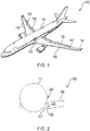
- the aircraft 10 includes a fuselage 11.
- a wing assembly including wings 12 extends from the fuselage 11.
- the wing assembly includes a wing box. It will be appreciated that the fuselage 11 and wings 12 may take a variety of different planform shapes and profiles depending on the particular application.
- Each wing 12 has a wing root at the fuselage 11, and a wing tip 14 at a distal end to the fuselage 11.
- the wing 12 has a leading edge 15 and a trailing edge 16.
- the fuselage 11 has a longitudinal axis.
- the longitudinal axis defines an "x-direction" as shown in Figure 1 .
- the "x-direction" of the aircraft 10 relates to a roll axis direction.
- a spanwise direction of the aircraft 10 is defined between the wing tips 14.
- the spanwise direction defines a "y-direction”.
- the spanwise direction relates to a pitch axis direction.
- a "z-direction" of the aircraft 10 extends perpendicular to the "x-direction" and "y-direction”.
- the "z-direction" relates to a yaw axis direction.
- the aerodynamic lift force which acts through the centre of pressure acts substantially in the z-direction.
- a centre wing box 17, and left and right wing sections 18 are assembled together. Root joints 19 connect the wing sections 18 to the centre wing box 17. Joints 20 form the root joint 19 between the centre wing box 17 and corresponding wing section 18. The joints 20 are typically connected between spars (not shown) to provide a structural interface.
- the joint 20 comprises a first joint part 30 and a second joint part 40.
- the first joint part 30 and the second joint part 40 are brought together to form an assembled joint.
- the first joint part 30 is mounted to a first component 31 and the second joint part 40 is mounted to a second component 41.
- the first and second components 31, 41 may be sub-assemblies of an aircraft assembly.
- the first and second joint parts 30, 40 may be integrally formed with the first and second components 31, 41 respectively.
- the first joint part 30 comprises a base 32. Fixings (not shown) mount the base 32 to the first component 31. Alternatively, the first component 31 forms the base 32.
- a spigot 33 upstands from the base 32.
- the spigot 33 is a pin.
- the spigot 33 is substantially cylindrical, although alternative shapes may be used.
- the spigot has a base end 34 and a free end 35. The free end 35 is distal from the base 32.
- the spigot 33 has a side surface 36.
- the spigot 33 is tapered.
- the taper of the spigot 33 is a small angle.
- the spigot 33 tapers from the base end 34 to the free end 35.
- the taper of the spigot 33 aids location of the spigot 33 in the second joint part 40.
- the first joint part 30 may be formed from any suitable material, for example titanium or aluminium.
- the second joint part 40 includes a housing 42 and a floating socket 50.
- the floating socket 50 is in an interior of the housing 42.
- the floating socket 50 is retained by the housing 42.
- the floating socket 50 is shown in an exploded view in Figures 5 and 6 , however it will be understood that the floating socket 50 is permanently retained in the housing 42.
- the housing 42 and floating socket 50 may be 3D printed, for example by additive layer manufacturing, or by another manufacturing process.
- the housing 42 is formed by two or more portions which may be permanently or releasably attached to each other to allow for insertion (and also possibly removal) of the floating socket 50 from the housing 42.
- the housing 42 comprises a body 43 and a mount 44.
- the mount 44 mounts the body 43 to the second component 41.
- the second component 41 may form the mount 44.
- Fixings (not shown) attach the mount 44 to the second component 41.
- Ribs 45 on the exterior of the body 43 provide structural strength to the body 43.
- the housing 42 has a joint face 46.
- the joint face 46 is distal from the mount 44.
- the joint face 46 is planar, although other arrangements are possible.
- the housing may be formed from any suitable material, for example titanium or aluminium.
- the housing 42 includes a chamber 47.
- the chamber 47 defines the interior of the housing 42.
- the chamber 47 is formed with a peripheral wall 47a and a base wall 47b.
- An end wall 47c of the chamber 47 opposes the base wall 47b.
- the end wall 47c defines the joint face 46.
- An opening 48 is formed in the housing 42.
- the opening 48 is in the end wall 47c.
- the opening 48 extends through the end wall 47c.
- the opening 48 extends from the joint face 46 to the chamber 47.
- the opening 48 provides access to the floating socket 50 in the chamber 47.
- the opening 48 has an opening axis.
- the end wall 47c defines a shoulder 49.
- the shoulder 49 defines the rim of the opening 48.
- the shoulder 49 retains the floating socket 50 in the chamber 47.
- the peripheral wall 47a of the chamber 47 has a generally circular profile.
- the peripheral wall 47a has an arcuate profile surface between the base wall 47b and end wall 47c, as shown in Figure 4 .
- the arcuate surface aids in restricting the floating socket 50 from jamming in the chamber 47.
- the chamber 47 has a diametric width. The diametric width is measured generally perpendicular to the axis of the opening 48.
- the chamber 47 has a depth.
- the chamber depth is between the base wall 47b and the end wall 47c.
- the chamber depth is at least substantially parallel to the axis of the opening 48.
- the opening 48 has a diametric width.
- the opening 48 is defined by the rim.
- the opening 48 is arranged to allow insertion of the spigot 33 into the chamber 47.
- An inlet 60 is provided to the chamber 47.
- the inlet 60 is configured to allow the insertion of a curable medium into the chamber 47.
- the inlet 60 comprises an injection port 61.
- the injection port 61 communicates between external of the housing 42 and the chamber 47.
- the injection port 61 is configured to receive an injection tool 70 as shown in Figure 8b .
- the injection tool 70 provides for the injection of a curable medium.
- the curable medium is an epoxy resin. Alternative curable mediums may be used.
- the floating socket 50 is retained in the chamber 47.
- the floating socket 50 is a ring.
- the floating socket 50 defines a sleeve with a spigot receiving bore 52.
- the spigot receiving bore 52 extends through the sleeve 51.
- the bore 52 extends partway into the sleeve 51.
- the sleeve 51 is substantially torus-shaped.
- the diameter of the bore 52 substantially corresponds the diameter of the spigot 33.
- the floating socket 50 acts as a bush.
- the sleeve 51 has a front side 53 and a rear side 54.
- the sleeve 51 has a peripheral surface 55.
- the peripheral surface 55 defines an outer circumference of the sleeve 51.
- the bore 52 defines a bore axis.
- the bore axis 52 is defined centrally in the floating socket 50.
- the overall dimensions of the floating socket 50 are smaller than the internal dimensions of the chamber 47.
- the diametric width of the chamber 47 is greater than the diametric width of the floating socket 50.
- the depth of the chamber 47 is greater than the thickness of the floating socket 50.
- the sleeve 51 is therefore free to float in the housing 42.
- the floating socket 50 is able to move in a radial direction, in an axial direction and to rotate about its axis.
- the floating socket 50 is formed as a one-piece component.
- the floating socket 50 is formed from a rigid material.
- the floating socket 50 may be bronze.
- the floating socket may be an alternative material, for example titanium or aluminium.
- a gap is formed between the floating socket 50 and the walls of the chamber 47. The diametric gap is shown in Figure 7 . It will be understood that the sleeve 51 is free to move in the chamber 47 to abut the walls 47a-c of the housing 42. The axis of the bore 52 may therefore be moved offset from the axis of the opening 48.
- the injection port 61 fluidly communicates with the chamber 47.
- the second joint part 40 may include an outlet which fluidly communicates the chamber with external to the housing 42.
- the opening 48 may act as the outlet.
- the joint 20 is initially arranged with the second joint part 40 spaced from the first joint part 30.
- the floating socket 50 is free to move in the housing 42.
- the housing 42 restrains movement of the floating socket 50.
- the first and second joint parts 30, 40 are brought together.
- the spigot 33 is aligned with the opening 48. It will be understood that the diameter of the opening 48 is greater than the diameter of the spigot 33.
- the first and second components 31, 41 are brought together with the spigot free end 35 of the spigot 33 being inserted into the housing 42. The free end 35 of the spigot 33 is inserted through the opening 48.
- the spigot 33 When the free end 35 of the spigot 33 is inserted into the housing 42, the spigot 33 is brought into contact with the floating socket 50. The free end 35 of the spigot 33 is inserted into the bore 52 of the floating socket 50.
- the spigot axis and opening axis may be misaligned.
- the bore axis and opening axis may be misaligned.
- the spigot 33 is received by the bore 52.
- the bore 52 is chamfered.
- the free end 35 of the spigot 33 contacts the chamfer to aid alignment of the floating socket 50 and spigot 33.
- the spigot 33 is therefore inserted into the sleeve 51 of the floating socket 50 to cause alignment of the sleeve 51 and the spigot 33.
- the taper of the spigot 33 aids to locate the spigot 33 in a close contact with the sleeve 51 when the first and second parts 30, 40 are brought fully together.
- the sleeve 51 acts as a bush of the spigot 33. When the first and second parts 30, 40 are brought together the spigot 33 may hold the floating socket 50 in an offset position in the housing 42.
- the length of the spigot 33 is less than the depth of the opening 48 and chamber 47. This helps to ensure that the free end 35 of the spigot 33 does not abut against the base wall 47b of the chamber 47.
- the injection tool 70 is brought into communication with the injection port 61.
- a curable medium such as an epoxy resin, is injected into the housing 42.
- the curable resin flows into the chamber 47.
- the curable medium 80 flows around the floating socket 50.
- the curable medium 80 contacts between the chamber walls 47a, 47b, 47c and the floating socket 50.
- the curable medium 80 fills the gap between the housing 42 and the sleeve 51.
- the curable medium 80 fills the chamber 47.
- the curable medium 80 flows through the opening 48, acting as an outlet.
- curable medium 80 covers the sleeve 51.
- the curable medium 80 at least substantially fills the gap between the floating socket 50 and the housing 42.
- the curable medium 80 is used to adhere the floating socket 50 with the housing 42.
- the curable medium 80 is then cured, as shown in Figure 8c .
- the curable medium 80 bonds the sleeve 51 in the housing 42.
- the position of the floating socket 50 in the housing 42 is fixed.
- the joint 20 is then formed in this assembled condition.
- the joint 20 is able to account for misalignment of the first and second joint parts 30, 40.
- the floating socket 50, and therefore the bore axis 52, is therefore fixed. It will be appreciated that the spigot 33 may be removed, and the position of the bore 52 in the housing 42 will be retained.
- the housing is formed in the above described in embodiment as a one-piece component, it will be understood that the housing may be two or more portions which are assembled together. In such an arrangement, the floating socket 50 may be insertable or removable from the housing. Such an arrangement is shown in Figures 9 and 10 . The arrangement of this embodiment is generally the same as that described above and so a detailed description will be omitted.
- the joint 90 comprises the first joint part 30 including the spigot 33, and the second joint part 40 including the housing 42 holding the floating socket 50.
- the housing 42 includes a first housing portion 91 and a second housing portion 92.
- the second housing portion 92 is received by the first housing portion 91.
- Attachment 94 on the first housing portion 91 is attached with attachments 95 on the second housing portion 92 to fix the first and second housing portions 91, 92 together.
- the housing 91 prevents removal of the floating socket 50 from the chamber 47.
- the second housing portion 92 is received on a rear side of the housing 42, that is distal from the joint face 46. As such, when the second joint part 40 is mounted to the second component 41 (not shown) the mounting of the second component 41 and the second joint part 40 acts as a failsafe against the second housing portion 92 becoming detached from the first housing portion 91.
- FIG. 11 to 13 An alternative arrangement is shown in Figures 11 to 13 .
- the arrangement in Figures 11 to 13 comprises a one-part housing or multiple part-housing as described above.
- the arrangement of this embodiment generally corresponds to the embodiments described above and so a detailed description will be omitted herein, and reference numerals for corresponding features will be retained.
- the floating socket 50 comprises a sleeve 100 with protrusions 101.
- the sleeve 100 comprises a bore 102.
- the bore 102 may protrude fully or part way through the sleeve 100.
- the bore 102 is substantially cylindrical and is configured to receive the spigot 33 of the first joint part 30.
- the floating socket is shown in Figures 11 and 12 in an exploded arrangement with the housing 42, however it will be understood that the floating socket 50 is retained in the housing 42.
- the protrusions 101 are teeth 105.
- the teeth 105 extend radially.
- the teeth 105 are formed on a peripheral side 106 of the sleeve 100.
- the teeth 105 are between the front and rear sides of the sleeve 100.
- the protrusions are formed by the teeth 105, it will be understood that alternative protrusion arrangements may be formed.
- the number of protrusions may vary.
- the teeth 105 are spaced around the periphery of the sleeve 100.
- the teeth 105 extend coaxially with the axis of the bore 102.
- the teeth 105, acting as protrusions are received in corresponding recesses 110 in the housing 42.
- the recesses 110 form the peripheral wall of the chamber 47.
- the recesses 110 are spaced around the chamber 47. Faces of the recesses 110 are spaced from the contact faces of the teeth 105. That is, the dimensions of the recesses 110 are greater than the dimensions of the protrusions 101. Such an arrangement is shown in Figure 13 .
- the dimensions of the chamber 47 are greater than the peripheral dimensions of the floating socket 50.
- the protrusions 101 are smaller than the recesses 110.
- the diametric width of the sleeve 100 between opposing tooth ends 107 is less than the diametric distance between the opposing recess spaces of the chamber 47.
- the sleeve 100 is able to float in the chamber 47.
- the protrusion arrangement restricts rotation of the sleeve 100 in the chamber 47. A limited amount of rotation is provided for, however the rotation of the sleeve 100 in the housing 42 is restricted.
- the uncured medium When the uncured medium is injected into the chamber 47, as described beforehand the uncured medium fills the gaps between the sleeve 100 and the chamber walls. The uncured medium flows in the recesses 110 and contacts between the recess walls 111 and the teeth 105, acting as protrusions. As such, when the uncured medium is cured then the position of the floating socket 50 with respect to the housing 42 is fixed. Relative movement of the sleeve and housing is prevented.
Landscapes
- Engineering & Computer Science (AREA)
- Mechanical Engineering (AREA)
- General Engineering & Computer Science (AREA)
- Aviation & Aerospace Engineering (AREA)
- Connection Of Plates (AREA)
Abstract
Description
- The present invention relates to an assembly-ready joint for an aircraft assembly. The present invention also relates to a joint part for joining with another joint part to form a joint for an aircraft, a joint construction for an aircraft assembly, an aircraft assembly, an aircraft, and a method of forming a joint for an aircraft assembly.
- Aircraft assemblies, such as wing assemblies are typically formed from a large number of components. The necessity to assemble large number of components leads to a complex structure. Typically, such a complex structure leads to a build-up of manufacturing tolerances. Such a tolerance build-up can lead to a misalignment of components to be assembled. This can lower the rate of assembly and reduce manufacturing efficiency.
- A tolerance build-up can lead to a substantive misalignment of components at joints. One such area where a build-up of tolerances is known to have an effect on the final fit of components is the root joint of spars of a wingbox. It is therefore desirable to minimise the effect of the tolerance build-up at joints of the assembly, for example at the root joint of the spars.
- According to an aspect of the invention, there is provided an assembly-ready joint for an aircraft assembly comprising: a first joint part comprising a spigot; a second joint part comprising a housing and a floating socket in an interior of the housing; wherein the second joint part is arranged to receive the spigot in the floating socket; and to receive a curable medium in the interior to contact between the housing and the floating socket.
- By 'assembly-ready' is meant two or more components that are arranged to be assembled, or are at least partially assembled.
- With the above arrangement, it is possible to absorb tolerance build-up by allowing the floating socket to be offset in the housing.
- The housing may comprise an inlet to the interior through which the curable medium is arranged to be received.
- The inlet may be an injection port in the housing. As such, a curable medium may be straightforwardly received in the housing.
- The curable medium may be a curable resin, such as an epoxy sealant. The curable resin may be a curable shim material, a curable putty or a curable sealant.
- The floating socket may comprise a spigot-receiving bore.
- The spigot-receiving bore may comprise a chamfer.
- The chamfer assists alignment of the floating socket and spigot when the components are brought together.
- The floating socket may be a sleeve. The sleeve may be a ring.
- Prior to the curable medium being cured in the interior, the floating socket may be movable in the interior of the housing in a direction at least substantially perpendicular to an axis of the bore.
- Prior to the curable medium being cured in the interior, the floating socket may be movable in the interior of the housing in a direction at least substantially parallel to an axis of the bore.
- The interior of the housing may comprise a chamber receiving the floating socket. A dimension of the chamber may be greater than a dimension of the socket.
- The second joint part may be arranged to receive a curable medium in the interior to contact substantially around a periphery of the floating socket.
- The assembly-ready joint may comprise an opening in the housing through which the spigot is arranged to extend to be received in the floating socket.
- A dimension of the opening may be greater than a dimension of the spigot.
- The opening may define an outlet through which air in the interior is able to flow from the interior when sealant is injected into the interior.
- The assembly-ready joint may comprise a shoulder extending around the opening retaining the sleeve in the interior of the housing.
- Prior to the curable medium being cured in the interior, the floating socket may be free to float at least 2mm in the housing.
- The housing may be configured to restrict movement of the floating socket in the housing.
- An axis of the bore may be arranged to be moved offset from an axis of the opening
- The assembly-ready joint may comprise protrusions extending in the interior arranged to restrict rotation of the floating socket in the interior of the housing.
- The protrusions may extend from the floating socket.
- The assembly-ready joint may comprise recesses in which the protrusions are received.
- An advantage of the above arrangement is that rotation of the floating socket about its axis is restricted.
- The spigot may be tapered.
- According to a further aspect of the invention, there is provided a joint construction for an aircraft assembly comprising: a first joint part comprising a spigot; a second joint part comprising a housing and a socket in an interior of the housing, with the spigot received in the floating socket; and a cured medium in the housing contacting between the housing and the socket.
- The cured medium may at least substantially surround a periphery of the socket.
- According to a further aspect of the invention, there is provided a joint part for joining with another joint part to form a joint for an aircraft, the joint part comprising: a housing and a floating socket in an interior of the housing; wherein the joint part is arranged to receive a spigot of the another joint part in the floating socket; and arranged to receive a curable medium in the housing to contact between the housing and the floating socket.
- According to a further aspect of the invention, there is provided an aircraft assembly comprising the joint part as described above, and a spigot configured to be received by the joint part.
- According to a further aspect of the invention, there is provided an aircraft comprising a joint construction as described above. The joint construction may form part of a root joint.
- According to a further aspect of the invention, there is provided a method of forming a joint for an aircraft assembly, the method comprising: aligning a first joint part comprising a spigot with a second joint part comprising a housing and a floating socket in an interior of the housing; inserting the spigot into the floating socket; and curing a curable medium in the interior of the housing to contact between the housing and the floating socket.
- The method may comprise, following inserting the spigot into the floating socket, injecting the curable medium in the interior of the housing.
- According to an aspect of the invention, there is provided a joint for an aircraft assembly comprising: a housing on a first component, the housing having a floating socket; a spigot received by the floating socket, and a cured medium in the housing adhering between the housing and the floating socket.
- Embodiments of the invention will now be described with reference to the accompanying drawings, in which:
-
Figure 1 is a perspective view of an aircraft; -
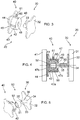
Figure 2 is a schematic view of a root joint of a wingbox of the aircraft shown inFigure 1 ; -
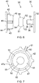
Figure 3 is a perspective view of an assembly ready joint prior to assembly of first and second joint parts for joining two components of the aircraft assembly; -
Figure 4 is a schematic cross-sectional view of the joint shown inFigure 3 ; -
Figure 5 is an exploded perspective view of the assembly ready joint shown inFigure 3 ; -
Figure 6 is an exploded side view of the assembly ready joint shown inFigure 3 . -
Figure 7 is a cross-sectional front view of the second part of the assembly ready joint shown inFigure 3 ; -
Figures 8a to 8c show a method of assembly of the joint shown inFigures 3 to 7 ; -
Figure 9 shows an exploded perspective view of another assembly-ready joint; -
Figure 10 shows an exploded side view of the assembly ready joint ofFigure 9 ; -
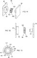
Figure 11 shows an exploded perspective view of another assembly-ready joint; -
Figure 12 shows an exploded side view of the assembly-ready joint ofFigure 11 ; and -
Figure 13 shows a cross-sectional front view of a second part of the assembly-ready joint ofFigure 11 . - An
aircraft 10 is shown inFigure 1 . Theaircraft 10 includes afuselage 11. A wingassembly including wings 12 extends from thefuselage 11. The wing assembly includes a wing box. It will be appreciated that thefuselage 11 andwings 12 may take a variety of different planform shapes and profiles depending on the particular application. Eachwing 12 has a wing root at thefuselage 11, and awing tip 14 at a distal end to thefuselage 11. Thewing 12 has aleading edge 15 and a trailingedge 16. - The
fuselage 11 has a longitudinal axis. The longitudinal axis defines an "x-direction" as shown inFigure 1 . The "x-direction" of theaircraft 10 relates to a roll axis direction. A spanwise direction of theaircraft 10 is defined between thewing tips 14. The spanwise direction defines a "y-direction". The spanwise direction relates to a pitch axis direction. A "z-direction" of theaircraft 10 extends perpendicular to the "x-direction" and "y-direction". The "z-direction" relates to a yaw axis direction. The aerodynamic lift force which acts through the centre of pressure acts substantially in the z-direction. - A
centre wing box 17, and left andright wing sections 18 are assembled together. Root joints 19 connect thewing sections 18 to thecentre wing box 17.Joints 20 form the root joint 19 between thecentre wing box 17 andcorresponding wing section 18. Thejoints 20 are typically connected between spars (not shown) to provide a structural interface. - Referring now to
Figures 3 to 6 , one of thejoints 20 for forming the root joint 19 will be described. Although the joint 20 is described with reference to the root joint 19, it will be understood that the joint 20 may be used in an alternative application, for example for joining two components in another part of the aircraft assembly, or in an alternative configuration. - The joint 20 comprises a first
joint part 30 and a secondjoint part 40. The firstjoint part 30 and the secondjoint part 40 are brought together to form an assembled joint. As shown inFigure 4 , the firstjoint part 30 is mounted to afirst component 31 and the secondjoint part 40 is mounted to asecond component 41. The first andsecond components joint parts second components - The first
joint part 30 comprises abase 32. Fixings (not shown) mount the base 32 to thefirst component 31. Alternatively, thefirst component 31 forms thebase 32. Aspigot 33 upstands from thebase 32. Thespigot 33 is a pin. Thespigot 33 is substantially cylindrical, although alternative shapes may be used. The spigot has abase end 34 and afree end 35. Thefree end 35 is distal from thebase 32. Thespigot 33 has aside surface 36. Thespigot 33 is tapered. The taper of thespigot 33 is a small angle. Thespigot 33 tapers from thebase end 34 to thefree end 35. The taper of thespigot 33 aids location of thespigot 33 in the secondjoint part 40. The firstjoint part 30 may be formed from any suitable material, for example titanium or aluminium. - The second
joint part 40 includes ahousing 42 and a floatingsocket 50. The floatingsocket 50 is in an interior of thehousing 42. The floatingsocket 50 is retained by thehousing 42. The floatingsocket 50 is shown in an exploded view inFigures 5 and6 , however it will be understood that the floatingsocket 50 is permanently retained in thehousing 42. For example, thehousing 42 and floatingsocket 50 may be 3D printed, for example by additive layer manufacturing, or by another manufacturing process. In another arrangement, thehousing 42 is formed by two or more portions which may be permanently or releasably attached to each other to allow for insertion (and also possibly removal) of the floatingsocket 50 from thehousing 42. - The
housing 42 comprises abody 43 and amount 44. Themount 44 mounts thebody 43 to thesecond component 41. Thesecond component 41 may form themount 44. Fixings (not shown) attach themount 44 to thesecond component 41.Ribs 45 on the exterior of thebody 43 provide structural strength to thebody 43. Thehousing 42 has ajoint face 46. Thejoint face 46 is distal from themount 44. Thejoint face 46 is planar, although other arrangements are possible. The housing may be formed from any suitable material, for example titanium or aluminium. - The
housing 42 includes achamber 47. Thechamber 47 defines the interior of thehousing 42. Thechamber 47 is formed with aperipheral wall 47a and abase wall 47b. Anend wall 47c of thechamber 47 opposes thebase wall 47b. Theend wall 47c defines thejoint face 46. Anopening 48 is formed in thehousing 42. Theopening 48 is in theend wall 47c. Theopening 48 extends through theend wall 47c. Theopening 48 extends from thejoint face 46 to thechamber 47. Theopening 48 provides access to the floatingsocket 50 in thechamber 47. Theopening 48 has an opening axis. Theend wall 47c defines a shoulder 49. The shoulder 49 defines the rim of theopening 48. The shoulder 49 retains the floatingsocket 50 in thechamber 47. - The
peripheral wall 47a of thechamber 47 has a generally circular profile. Theperipheral wall 47a has an arcuate profile surface between thebase wall 47b and endwall 47c, as shown inFigure 4 . The arcuate surface aids in restricting the floatingsocket 50 from jamming in thechamber 47. Thechamber 47 has a diametric width. The diametric width is measured generally perpendicular to the axis of theopening 48. Thechamber 47 has a depth. The chamber depth is between thebase wall 47b and theend wall 47c. The chamber depth is at least substantially parallel to the axis of theopening 48. - The
opening 48 has a diametric width. Theopening 48 is defined by the rim. Theopening 48 is arranged to allow insertion of thespigot 33 into thechamber 47. - An
inlet 60 is provided to thechamber 47. Theinlet 60 is configured to allow the insertion of a curable medium into thechamber 47. Theinlet 60 comprises aninjection port 61. Theinjection port 61 communicates between external of thehousing 42 and thechamber 47. Theinjection port 61 is configured to receive aninjection tool 70 as shown inFigure 8b . Theinjection tool 70 provides for the injection of a curable medium. The curable medium is an epoxy resin. Alternative curable mediums may be used. - The floating
socket 50 is retained in thechamber 47. The floatingsocket 50 is a ring. The floatingsocket 50 defines a sleeve with a spigot receiving bore 52. The spigot receiving bore 52 extends through thesleeve 51. In an alternative arrangement, thebore 52 extends partway into thesleeve 51. Thesleeve 51 is substantially torus-shaped. The diameter of thebore 52 substantially corresponds the diameter of thespigot 33. The floatingsocket 50 acts as a bush. Thesleeve 51 has afront side 53 and arear side 54. Thesleeve 51 has aperipheral surface 55. Theperipheral surface 55 defines an outer circumference of thesleeve 51. Thebore 52 defines a bore axis. Thebore axis 52 is defined centrally in the floatingsocket 50. - The overall dimensions of the floating
socket 50 are smaller than the internal dimensions of thechamber 47. The diametric width of thechamber 47 is greater than the diametric width of the floatingsocket 50. The depth of thechamber 47 is greater than the thickness of the floatingsocket 50. Thesleeve 51 is therefore free to float in thehousing 42. The floatingsocket 50 is able to move in a radial direction, in an axial direction and to rotate about its axis. - The floating
socket 50 is formed as a one-piece component. The floatingsocket 50 is formed from a rigid material. The floatingsocket 50 may be bronze. The floating socket may be an alternative material, for example titanium or aluminium. A gap is formed between the floatingsocket 50 and the walls of thechamber 47. The diametric gap is shown inFigure 7 . It will be understood that thesleeve 51 is free to move in thechamber 47 to abut thewalls 47a-c of thehousing 42. The axis of thebore 52 may therefore be moved offset from the axis of theopening 48. Theinjection port 61 fluidly communicates with thechamber 47. The secondjoint part 40 may include an outlet which fluidly communicates the chamber with external to thehousing 42. Theopening 48 may act as the outlet. - Referring now to
Figures 8a, 8b and 8c , assembly of the joint 20 will now be described. The joint 20 is initially arranged with the secondjoint part 40 spaced from the firstjoint part 30. At this stage, the floatingsocket 50 is free to move in thehousing 42. Thehousing 42 restrains movement of the floatingsocket 50. - The first and second
joint parts spigot 33 is aligned with theopening 48. It will be understood that the diameter of theopening 48 is greater than the diameter of thespigot 33. The first andsecond components free end 35 of thespigot 33 being inserted into thehousing 42. Thefree end 35 of thespigot 33 is inserted through theopening 48. - When the
free end 35 of thespigot 33 is inserted into thehousing 42, thespigot 33 is brought into contact with the floatingsocket 50. Thefree end 35 of thespigot 33 is inserted into thebore 52 of the floatingsocket 50. - The spigot axis and opening axis may be misaligned. Similarly, the bore axis and opening axis may be misaligned. The
spigot 33 is received by thebore 52. Thebore 52 is chamfered. As such, thefree end 35 of thespigot 33 contacts the chamfer to aid alignment of the floatingsocket 50 andspigot 33. Thespigot 33 is therefore inserted into thesleeve 51 of the floatingsocket 50 to cause alignment of thesleeve 51 and thespigot 33. The taper of thespigot 33 aids to locate thespigot 33 in a close contact with thesleeve 51 when the first andsecond parts sleeve 51 acts as a bush of thespigot 33. When the first andsecond parts spigot 33 may hold the floatingsocket 50 in an offset position in thehousing 42. - The length of the
spigot 33 is less than the depth of theopening 48 andchamber 47. This helps to ensure that thefree end 35 of thespigot 33 does not abut against thebase wall 47b of thechamber 47. - As shown in
Figure 8b , when thespigot 33 is received by thesleeve 51, a peripheral gap is formed around the floatingsocket 50, between the floatingsocket 50 and theperipheral wall 47a of thechamber 47. Thespigot 33 and floatingsocket 50 are offset from thehousing 42. - The
injection tool 70 is brought into communication with theinjection port 61. A curable medium, such as an epoxy resin, is injected into thehousing 42. The curable resin flows into thechamber 47. Thecurable medium 80 flows around the floatingsocket 50. The curable medium 80 contacts between thechamber walls socket 50. Thecurable medium 80 fills the gap between thehousing 42 and thesleeve 51. Thecurable medium 80 fills thechamber 47. Thecurable medium 80 flows through theopening 48, acting as an outlet. - Once a quantity of
curable medium 80 has been injected to fill thechamber 47 injection of the curable medium is stopped. Thecurable medium 80 covers thesleeve 51. Thecurable medium 80 at least substantially fills the gap between the floatingsocket 50 and thehousing 42. Thecurable medium 80 is used to adhere the floatingsocket 50 with thehousing 42. - The
curable medium 80 is then cured, as shown inFigure 8c . Thecurable medium 80 bonds thesleeve 51 in thehousing 42. As such, the position of the floatingsocket 50 in thehousing 42 is fixed. The joint 20 is then formed in this assembled condition. As such, the joint 20 is able to account for misalignment of the first and secondjoint parts socket 50, and therefore thebore axis 52, is therefore fixed. It will be appreciated that thespigot 33 may be removed, and the position of thebore 52 in thehousing 42 will be retained. - Although the housing is formed in the above described in embodiment as a one-piece component, it will be understood that the housing may be two or more portions which are assembled together. In such an arrangement, the floating
socket 50 may be insertable or removable from the housing. Such an arrangement is shown inFigures 9 and 10 . The arrangement of this embodiment is generally the same as that described above and so a detailed description will be omitted. - In this embodiment, the joint 90 comprises the first
joint part 30 including thespigot 33, and the secondjoint part 40 including thehousing 42 holding the floatingsocket 50. Thehousing 42 includes afirst housing portion 91 and asecond housing portion 92. Thesecond housing portion 92 is received by thefirst housing portion 91. When thesecond housing portion 92 is removed from thefirst housing portion 91, thechamber 47 is accessible to insert the floatingsocket 50 into thechamber 47.Attachment 94 on thefirst housing portion 91 is attached withattachments 95 on thesecond housing portion 92 to fix the first andsecond housing portions housing 91 prevents removal of the floatingsocket 50 from thechamber 47. - In this embodiment, the
second housing portion 92 is received on a rear side of thehousing 42, that is distal from thejoint face 46. As such, when the secondjoint part 40 is mounted to the second component 41 (not shown) the mounting of thesecond component 41 and the secondjoint part 40 acts as a failsafe against thesecond housing portion 92 becoming detached from thefirst housing portion 91. - An alternative arrangement is shown in
Figures 11 to 13 . The arrangement inFigures 11 to 13 comprises a one-part housing or multiple part-housing as described above. The arrangement of this embodiment generally corresponds to the embodiments described above and so a detailed description will be omitted herein, and reference numerals for corresponding features will be retained. - In the embodiment shown in
Figures 11 to 13 , the floatingsocket 50 comprises asleeve 100 withprotrusions 101. Thesleeve 100 comprises abore 102. Thebore 102 may protrude fully or part way through thesleeve 100. Thebore 102 is substantially cylindrical and is configured to receive thespigot 33 of the firstjoint part 30. The floating socket is shown inFigures 11 and 12 in an exploded arrangement with thehousing 42, however it will be understood that the floatingsocket 50 is retained in thehousing 42. - The
protrusions 101 are teeth 105. The teeth 105 extend radially. The teeth 105 are formed on aperipheral side 106 of thesleeve 100. The teeth 105 are between the front and rear sides of thesleeve 100. Although in the shown embodiment the protrusions are formed by the teeth 105, it will be understood that alternative protrusion arrangements may be formed. Furthermore, the number of protrusions may vary. The teeth 105 are spaced around the periphery of thesleeve 100. The teeth 105 extend coaxially with the axis of thebore 102. The teeth 105, acting as protrusions are received in corresponding recesses 110 in thehousing 42. The recesses 110 form the peripheral wall of thechamber 47. The recesses 110 are spaced around thechamber 47. Faces of the recesses 110 are spaced from the contact faces of the teeth 105. That is, the dimensions of the recesses 110 are greater than the dimensions of theprotrusions 101. Such an arrangement is shown inFigure 13 . - As described above, the dimensions of the
chamber 47 are greater than the peripheral dimensions of the floatingsocket 50. As such, theprotrusions 101 are smaller than the recesses 110. The diametric width of thesleeve 100 between opposing tooth ends 107 is less than the diametric distance between the opposing recess spaces of thechamber 47. As such, thesleeve 100 is able to float in thechamber 47. The protrusion arrangement restricts rotation of thesleeve 100 in thechamber 47. A limited amount of rotation is provided for, however the rotation of thesleeve 100 in thehousing 42 is restricted. - When the uncured medium is injected into the
chamber 47, as described beforehand the uncured medium fills the gaps between thesleeve 100 and the chamber walls. The uncured medium flows in the recesses 110 and contacts between therecess walls 111 and the teeth 105, acting as protrusions. As such, when the uncured medium is cured then the position of the floatingsocket 50 with respect to thehousing 42 is fixed. Relative movement of the sleeve and housing is prevented. - Although in the above described embodiments the joint is described with reference to an aircraft, it will be understood that the joint may be used with alternative assemblies.
- Where the word 'or' appears this is to be construed to mean 'and/or' such that items referred to are not necessarily mutually exclusive and may be used in any appropriate combination.
- Although the invention has been described above with reference to one or more preferred embodiments, it will be appreciated that various changes or modifications may be made without departing from the scope of the invention as defined in the appended claims.
Claims (15)
- An assembly-ready joint for an aircraft assembly comprising:a first joint part comprising a spigot;a second joint part comprising a housing and a floating socket in an interior of the housing;wherein the second joint part is arranged to receive the spigot in the floating socket; and to receive a curable medium in the interior of the housing to contact between the housing and the floating socket.
- The assembly-ready joint of claim 1, wherein the housing comprises an inlet to the interior through which the curable medium is arranged to be received, and preferably wherein the inlet is an injection port in the housing.
- The assembly-ready joint of any preceding claim wherein the floating socket comprises a spigot-receiving bore, and preferably wherein the spigot-receiving bore comprises a chamfer.
- The assembly-ready joint of claim 3, wherein, prior to the curable medium being cured in the interior, the floating socket is movable in the interior of the housing in a direction perpendicular or parallel to an axis of the spigot-receiving bore, and preferably wherein the interior of the housing comprises a chamber receiving the floating socket, and wherein a dimension of the chamber is greater than a dimension of the socket.
- The assembly-ready joint of any preceding claim, wherein the second joint part is arranged to receive a curable medium in the interior to contact substantially around a periphery of the floating socket.
- The assembly-ready joint of any preceding claim, comprising an opening in the housing through which the spigot is arranged to extend to be received in the floating socket, preferably wherein a dimension of the opening is greater than a dimension of the spigot, and preferably wherein the opening defines an outlet through which air in the interior is able to flow from the interior when sealant is injected into the interior, and preferably further comprising a shoulder extending around the opening retaining the sleeve in the interior of the housing.
- The assembly-ready joint of any preceding claim wherein, prior to the curable medium being cured in the interior, the floating socket is free to float at least 2mm in the housing, and/or wherein the housing is configured to restrict movement of the floating socket in the housing.
- The assembly-ready joint of any preceding claim when dependent on claim 3, wherein an axis of the bore is arranged to be moved offset from an axis of the opening
- The assembly-ready joint of any preceding claim, comprising protrusions extending in the interior of the housing arranged to restrict rotation of the floating socket in the interior of the housing, and preferably wherein the protrusions extend from the floating socket, and preferably further comprising recesses in which the protrusions are received.
- The assembly-ready joint of any preceding claim, wherein the spigot is tapered.
- A joint construction for an aircraft assembly comprising the assembly-ready joint of claim 1,wherein the spigot is received in the floating socket;and further comprising a cured medium in the housing contacting between the housing and the socket.
- A joint construction of claim 11, wherein the joint construction is part of an aircraft root joint.
- A joint part for joining with another joint part to form a joint of an aircraft, the joint part comprising:a housing; anda floating socket in an interior of the housing;wherein the joint part is arranged to receive a spigot of the another joint part in the floating socket; and arranged to receive a curable medium in the housing to contact between the housing and the floating socket.
- A method of forming a joint for an aircraft assembly, the method comprising:aligning a first joint part comprising a spigot with a second joint part comprising a housing and a floating socket in an interior of the housing;inserting the spigot into the floating socket; andcuring a curable medium in the interior of the housing to contact between the housing and the floating socket.
- The method of claim 14 comprising, following inserting the spigot into the floating socket, injecting the curable medium in the interior of the housing.
Applications Claiming Priority (1)
| Application Number | Priority Date | Filing Date | Title |
|---|---|---|---|
| GB1904353.8A GB2582631A (en) | 2019-03-28 | 2019-03-28 | A joint for an aircraft assembly |
Publications (2)
| Publication Number | Publication Date |
|---|---|
| EP3718877A1 true EP3718877A1 (en) | 2020-10-07 |
| EP3718877B1 EP3718877B1 (en) | 2024-07-17 |
Family
ID=66442836
Family Applications (1)
| Application Number | Title | Priority Date | Filing Date |
|---|---|---|---|
| EP20165734.3A Active EP3718877B1 (en) | 2019-03-28 | 2020-03-25 | A joint for an aircraft assembly |
Country Status (4)
| Country | Link |
|---|---|
| US (1) | US11703071B2 (en) |
| EP (1) | EP3718877B1 (en) |
| CN (1) | CN111749963B (en) |
| GB (1) | GB2582631A (en) |
Cited By (1)
| Publication number | Priority date | Publication date | Assignee | Title |
|---|---|---|---|---|
| EP4596899A1 (en) * | 2024-02-02 | 2025-08-06 | Airbus Operations GmbH | Connecting interface structure and method of connecting a cabin element to a primary structure |
Families Citing this family (3)
| Publication number | Priority date | Publication date | Assignee | Title |
|---|---|---|---|---|
| US12523244B2 (en) * | 2021-10-28 | 2026-01-13 | Honeywell International Inc. | Locking positioning systems |
| GB2641128A (en) * | 2024-05-17 | 2025-11-19 | Airbus Operations Ltd | Aircraft access door |
| GB2643516A (en) * | 2024-08-16 | 2026-02-25 | Airbus Operations Ltd | Joint assembly |
Citations (6)
| Publication number | Priority date | Publication date | Assignee | Title |
|---|---|---|---|---|
| US3621557A (en) * | 1969-06-06 | 1971-11-23 | Rex Chainbelt Inc | Insert for sandwich panels and method of installation |
| EP0415505A2 (en) * | 1989-08-31 | 1991-03-06 | Richard F. Gauron | Inset panel fastener with floating member |
| US8359715B2 (en) * | 2007-02-28 | 2013-01-29 | GM Global Technology Operations LLC | Trim clip |
| EP3059459A1 (en) * | 2015-02-19 | 2016-08-24 | Mitsubishi Aircraft Corporation | Penetrated floating nut |
| EP3069988A1 (en) * | 2015-03-17 | 2016-09-21 | Airbus Operations Limited | A connector between two aircraft components, such as a wing and wing tip device |
| EP3130534A1 (en) * | 2014-09-30 | 2017-02-15 | Commercial Aircraft Corporation Of China Ltd | Airplane wing assembly |
Family Cites Families (28)
| Publication number | Priority date | Publication date | Assignee | Title |
|---|---|---|---|---|
| US2820499A (en) * | 1954-12-17 | 1958-01-21 | Mcdonnell Aircraft Corp | Floating, swivelling anchor nut |
| US3016578A (en) * | 1957-12-11 | 1962-01-16 | Frederick W Rohe | Moldable insert panel and method of assembly |
| GB876106A (en) * | 1959-11-11 | 1961-08-30 | Frederick William Rohe | An improved nut fastener for use with sandwich-type panels |
| US3510916A (en) * | 1965-06-21 | 1970-05-12 | Shur Lok Corp | Device for installing molded-in inserts in sandwich panels |
| US3339609A (en) * | 1965-08-02 | 1967-09-05 | Delron Company Inc | Floating nut insert |
| US3504723A (en) * | 1968-05-27 | 1970-04-07 | Delron Fastener Division Rex C | Floating nut insert |
| US3884006A (en) * | 1973-01-05 | 1975-05-20 | Robert W Dietlein | Sandwich panel insert |
| DE3042432C2 (en) * | 1980-11-11 | 1984-11-15 | Messerschmitt-Bölkow-Blohm GmbH, 8000 München | Fastening device for a sandwich panel to hold fastening screws with an expansion dowel and threaded insert |
| US4812193A (en) * | 1986-12-22 | 1989-03-14 | Gauron Richard F | Inset panel fastener and method of using |
| JP2771869B2 (en) * | 1989-11-24 | 1998-07-02 | 日本電信電話株式会社 | Plug-in connector float structure |
| US5240543A (en) * | 1990-06-11 | 1993-08-31 | Atr International, Inc. | Apparatus for and method of seating a fastener insert in a honeycomb panel |
| US5378099A (en) * | 1993-07-01 | 1995-01-03 | Gauron; Richard F. | Inset panel fastener with shoulder-engaging floating member |
| US5632582A (en) * | 1996-07-10 | 1997-05-27 | Gauron; Richard F. | Inset panel fastener with two-part stem |
| US20070297869A1 (en) * | 2006-06-26 | 2007-12-27 | Kunda James J | Through insert with floating capability |
| CN101688549B (en) * | 2007-07-12 | 2011-11-30 | 百乐仕株式会社 | Latching device |
| CN101970887A (en) * | 2008-01-11 | 2011-02-09 | 赫尔曼米勒有限公司 | Connection components |
| EP2427285B1 (en) * | 2009-05-04 | 2017-08-23 | Gkn Sinter Metals, Llc | Adhesive joining for powder metal components |
| JP5313805B2 (en) * | 2009-08-07 | 2013-10-09 | スリーエム イノベイティブ プロパティズ カンパニー | Floating connector |
| US8579570B2 (en) * | 2011-08-11 | 2013-11-12 | GM Global Technology Operations LLC | Fastener attaching a component to a panel |
| JP5931458B2 (en) * | 2012-01-17 | 2016-06-08 | 三菱航空機株式会社 | How to install lightning-resistant fasteners and lightning-resistant fasteners |
| CN202616468U (en) * | 2012-06-06 | 2012-12-19 | 公牛集团有限公司 | Floating mechanism for electric shock preventing socket |
| EP2909004B1 (en) * | 2012-10-17 | 2019-01-23 | RUAG Schweiz AG | Method ans system for inserting an insert element in a panel |
| US9003662B2 (en) * | 2013-01-31 | 2015-04-14 | B/E Aerospace, Inc. | Insert and method for anchoring in a cored panel |
| US9829030B2 (en) * | 2013-04-19 | 2017-11-28 | Airbus Operations Limited | Injectable cap |
| WO2015073621A1 (en) * | 2013-11-13 | 2015-05-21 | C&D Zodiac, Inc. | Aircraft interior bracket |
| US9446488B2 (en) * | 2014-05-21 | 2016-09-20 | The Boeing Company | Self-locking molded-in blind inserts |
| EP3247914B1 (en) * | 2015-01-23 | 2023-08-16 | Barco N.V. | Connecting device for improved alignment |
| GB2535518A (en) * | 2015-02-20 | 2016-08-24 | Airbus Operations Ltd | Cap with injected sealant |
-
2019
- 2019-03-28 GB GB1904353.8A patent/GB2582631A/en not_active Withdrawn
-
2020
- 2020-03-25 EP EP20165734.3A patent/EP3718877B1/en active Active
- 2020-03-26 CN CN202010223281.2A patent/CN111749963B/en active Active
- 2020-03-27 US US16/832,249 patent/US11703071B2/en active Active
Patent Citations (6)
| Publication number | Priority date | Publication date | Assignee | Title |
|---|---|---|---|---|
| US3621557A (en) * | 1969-06-06 | 1971-11-23 | Rex Chainbelt Inc | Insert for sandwich panels and method of installation |
| EP0415505A2 (en) * | 1989-08-31 | 1991-03-06 | Richard F. Gauron | Inset panel fastener with floating member |
| US8359715B2 (en) * | 2007-02-28 | 2013-01-29 | GM Global Technology Operations LLC | Trim clip |
| EP3130534A1 (en) * | 2014-09-30 | 2017-02-15 | Commercial Aircraft Corporation Of China Ltd | Airplane wing assembly |
| EP3059459A1 (en) * | 2015-02-19 | 2016-08-24 | Mitsubishi Aircraft Corporation | Penetrated floating nut |
| EP3069988A1 (en) * | 2015-03-17 | 2016-09-21 | Airbus Operations Limited | A connector between two aircraft components, such as a wing and wing tip device |
Cited By (1)
| Publication number | Priority date | Publication date | Assignee | Title |
|---|---|---|---|---|
| EP4596899A1 (en) * | 2024-02-02 | 2025-08-06 | Airbus Operations GmbH | Connecting interface structure and method of connecting a cabin element to a primary structure |
Also Published As
| Publication number | Publication date |
|---|---|
| GB201904353D0 (en) | 2019-05-15 |
| CN111749963A (en) | 2020-10-09 |
| GB2582631A (en) | 2020-09-30 |
| EP3718877B1 (en) | 2024-07-17 |
| CN111749963B (en) | 2024-08-02 |
| US11703071B2 (en) | 2023-07-18 |
| US20200309174A1 (en) | 2020-10-01 |
Similar Documents
| Publication | Publication Date | Title |
|---|---|---|
| US11703071B2 (en) | Joint for an aircraft assembly | |
| US9562559B2 (en) | Connecting arrangement and also a method | |
| CN102369138B (en) | Coupling component, joint comprising the joint and method for preparing the joint | |
| EP3480107A1 (en) | Aircraft framework assembly, aircraft structural framework and aircraft with an aircraft structural framework | |
| MX2007001989A (en) | Gun-drill. | |
| EP3478985B1 (en) | Adapter for an isolation mount design | |
| WO2016050198A1 (en) | Airplane wing assembly | |
| US6254349B1 (en) | Device and method for detachably connecting an impeller to a pinion shaft in a high speed fluid compressor | |
| EP3931436B1 (en) | Jointed wind turbine rotor blade with chord-wise extending pin bushings designed to minimize chord-wise gap | |
| CN216951176U (en) | Quick-release lock | |
| CN110636937B (en) | Method for locking plastic plug connector for plugging steering box by using ultrasonic wave | |
| CN206981787U (en) | A kind of Expansion core tool | |
| CN116733922B (en) | Electronic expansion valve | |
| CN114810219B (en) | Aero-engine | |
| JP2006273039A (en) | Equipment mounting insert and its mounting method | |
| CN116066461A (en) | Connection element, first part, connection structure, manufacturing method and connection method | |
| CN110332311B (en) | Assembling method of B-shaped rubber sealing structure | |
| CN214930166U (en) | Wing piece quick assembly disassembly and replacement structure without damaging surface shape of wing piece | |
| EP4585519A1 (en) | Jig for spark containment caps | |
| CN216883723U (en) | Sunken stepped coaxial assembly tool | |
| CN114310791B (en) | Sunken stepped coaxial assembly fixture and use method thereof | |
| CN120621699B (en) | A fast docking and locking device and method for unmanned aerial vehicles based on open bushings | |
| CN215146128U (en) | Parking axle and sector plate welding position anchor clamps | |
| US9938857B2 (en) | Quick change insert | |
| CN212797057U (en) | Worm of automobile electric steering gear |
Legal Events
| Date | Code | Title | Description |
|---|---|---|---|
| PUAI | Public reference made under article 153(3) epc to a published international application that has entered the european phase |
Free format text: ORIGINAL CODE: 0009012 |
|
| STAA | Information on the status of an ep patent application or granted ep patent |
Free format text: STATUS: THE APPLICATION HAS BEEN PUBLISHED |
|
| AK | Designated contracting states |
Kind code of ref document: A1 Designated state(s): AL AT BE BG CH CY CZ DE DK EE ES FI FR GB GR HR HU IE IS IT LI LT LU LV MC MK MT NL NO PL PT RO RS SE SI SK SM TR |
|
| AX | Request for extension of the european patent |
Extension state: BA ME |
|
| STAA | Information on the status of an ep patent application or granted ep patent |
Free format text: STATUS: REQUEST FOR EXAMINATION WAS MADE |
|
| 17P | Request for examination filed |
Effective date: 20210324 |
|
| RBV | Designated contracting states (corrected) |
Designated state(s): AL AT BE BG CH CY CZ DE DK EE ES FI FR GB GR HR HU IE IS IT LI LT LU LV MC MK MT NL NO PL PT RO RS SE SI SK SM TR |
|
| STAA | Information on the status of an ep patent application or granted ep patent |
Free format text: STATUS: EXAMINATION IS IN PROGRESS |
|
| 17Q | First examination report despatched |
Effective date: 20211005 |
|
| GRAP | Despatch of communication of intention to grant a patent |
Free format text: ORIGINAL CODE: EPIDOSNIGR1 |
|
| STAA | Information on the status of an ep patent application or granted ep patent |
Free format text: STATUS: GRANT OF PATENT IS INTENDED |
|
| RIC1 | Information provided on ipc code assigned before grant |
Ipc: F16B 5/06 20060101ALN20240320BHEP Ipc: B64C 3/00 20060101ALN20240320BHEP Ipc: F16B 19/02 20060101ALI20240320BHEP Ipc: F16B 11/00 20060101ALI20240320BHEP Ipc: F16B 39/02 20060101ALI20240320BHEP Ipc: F16B 37/04 20060101ALI20240320BHEP Ipc: F16B 5/02 20060101ALI20240320BHEP Ipc: F16B 3/00 20060101ALI20240320BHEP Ipc: B64C 1/26 20060101AFI20240320BHEP |
|
| INTG | Intention to grant announced |
Effective date: 20240419 |
|
| GRAS | Grant fee paid |
Free format text: ORIGINAL CODE: EPIDOSNIGR3 |
|
| GRAA | (expected) grant |
Free format text: ORIGINAL CODE: 0009210 |
|
| STAA | Information on the status of an ep patent application or granted ep patent |
Free format text: STATUS: THE PATENT HAS BEEN GRANTED |
|
| AK | Designated contracting states |
Kind code of ref document: B1 Designated state(s): AL AT BE BG CH CY CZ DE DK EE ES FI FR GB GR HR HU IE IS IT LI LT LU LV MC MK MT NL NO PL PT RO RS SE SI SK SM TR |
|
| REG | Reference to a national code |
Ref country code: CH Ref legal event code: EP |
|
| REG | Reference to a national code |
Ref country code: DE Ref legal event code: R096 Ref document number: 602020033969 Country of ref document: DE |
|
| REG | Reference to a national code |
Ref country code: IE Ref legal event code: FG4D |
|
| REG | Reference to a national code |
Ref country code: LT Ref legal event code: MG9D |
|
| REG | Reference to a national code |
Ref country code: NL Ref legal event code: MP Effective date: 20240717 |
|
| PG25 | Lapsed in a contracting state [announced via postgrant information from national office to epo] |
Ref country code: PT Free format text: LAPSE BECAUSE OF FAILURE TO SUBMIT A TRANSLATION OF THE DESCRIPTION OR TO PAY THE FEE WITHIN THE PRESCRIBED TIME-LIMIT Effective date: 20241118 |
|
| REG | Reference to a national code |
Ref country code: AT Ref legal event code: MK05 Ref document number: 1703882 Country of ref document: AT Kind code of ref document: T Effective date: 20240717 |
|
| PG25 | Lapsed in a contracting state [announced via postgrant information from national office to epo] |
Ref country code: NL Free format text: LAPSE BECAUSE OF FAILURE TO SUBMIT A TRANSLATION OF THE DESCRIPTION OR TO PAY THE FEE WITHIN THE PRESCRIBED TIME-LIMIT Effective date: 20240717 |
|
| PG25 | Lapsed in a contracting state [announced via postgrant information from national office to epo] |
Ref country code: PT Free format text: LAPSE BECAUSE OF FAILURE TO SUBMIT A TRANSLATION OF THE DESCRIPTION OR TO PAY THE FEE WITHIN THE PRESCRIBED TIME-LIMIT Effective date: 20241118 Ref country code: NL Free format text: LAPSE BECAUSE OF FAILURE TO SUBMIT A TRANSLATION OF THE DESCRIPTION OR TO PAY THE FEE WITHIN THE PRESCRIBED TIME-LIMIT Effective date: 20240717 |
|
| PG25 | Lapsed in a contracting state [announced via postgrant information from national office to epo] |
Ref country code: NO Free format text: LAPSE BECAUSE OF FAILURE TO SUBMIT A TRANSLATION OF THE DESCRIPTION OR TO PAY THE FEE WITHIN THE PRESCRIBED TIME-LIMIT Effective date: 20241017 |
|
| PG25 | Lapsed in a contracting state [announced via postgrant information from national office to epo] |
Ref country code: PL Free format text: LAPSE BECAUSE OF FAILURE TO SUBMIT A TRANSLATION OF THE DESCRIPTION OR TO PAY THE FEE WITHIN THE PRESCRIBED TIME-LIMIT Effective date: 20240717 Ref country code: GR Free format text: LAPSE BECAUSE OF FAILURE TO SUBMIT A TRANSLATION OF THE DESCRIPTION OR TO PAY THE FEE WITHIN THE PRESCRIBED TIME-LIMIT Effective date: 20241018 Ref country code: FI Free format text: LAPSE BECAUSE OF FAILURE TO SUBMIT A TRANSLATION OF THE DESCRIPTION OR TO PAY THE FEE WITHIN THE PRESCRIBED TIME-LIMIT Effective date: 20240717 |
|
| PG25 | Lapsed in a contracting state [announced via postgrant information from national office to epo] |
Ref country code: BG Free format text: LAPSE BECAUSE OF FAILURE TO SUBMIT A TRANSLATION OF THE DESCRIPTION OR TO PAY THE FEE WITHIN THE PRESCRIBED TIME-LIMIT Effective date: 20240717 |
|
| PG25 | Lapsed in a contracting state [announced via postgrant information from national office to epo] |
Ref country code: LV Free format text: LAPSE BECAUSE OF FAILURE TO SUBMIT A TRANSLATION OF THE DESCRIPTION OR TO PAY THE FEE WITHIN THE PRESCRIBED TIME-LIMIT Effective date: 20240717 |
|
| PG25 | Lapsed in a contracting state [announced via postgrant information from national office to epo] |
Ref country code: IS Free format text: LAPSE BECAUSE OF FAILURE TO SUBMIT A TRANSLATION OF THE DESCRIPTION OR TO PAY THE FEE WITHIN THE PRESCRIBED TIME-LIMIT Effective date: 20241117 Ref country code: AT Free format text: LAPSE BECAUSE OF FAILURE TO SUBMIT A TRANSLATION OF THE DESCRIPTION OR TO PAY THE FEE WITHIN THE PRESCRIBED TIME-LIMIT Effective date: 20240717 |
|
| PG25 | Lapsed in a contracting state [announced via postgrant information from national office to epo] |
Ref country code: HR Free format text: LAPSE BECAUSE OF FAILURE TO SUBMIT A TRANSLATION OF THE DESCRIPTION OR TO PAY THE FEE WITHIN THE PRESCRIBED TIME-LIMIT Effective date: 20240717 |
|
| PG25 | Lapsed in a contracting state [announced via postgrant information from national office to epo] |
Ref country code: RS Free format text: LAPSE BECAUSE OF FAILURE TO SUBMIT A TRANSLATION OF THE DESCRIPTION OR TO PAY THE FEE WITHIN THE PRESCRIBED TIME-LIMIT Effective date: 20241017 Ref country code: ES Free format text: LAPSE BECAUSE OF FAILURE TO SUBMIT A TRANSLATION OF THE DESCRIPTION OR TO PAY THE FEE WITHIN THE PRESCRIBED TIME-LIMIT Effective date: 20240717 |
|
| PG25 | Lapsed in a contracting state [announced via postgrant information from national office to epo] |
Ref country code: RS Free format text: LAPSE BECAUSE OF FAILURE TO SUBMIT A TRANSLATION OF THE DESCRIPTION OR TO PAY THE FEE WITHIN THE PRESCRIBED TIME-LIMIT Effective date: 20241017 Ref country code: PL Free format text: LAPSE BECAUSE OF FAILURE TO SUBMIT A TRANSLATION OF THE DESCRIPTION OR TO PAY THE FEE WITHIN THE PRESCRIBED TIME-LIMIT Effective date: 20240717 Ref country code: NO Free format text: LAPSE BECAUSE OF FAILURE TO SUBMIT A TRANSLATION OF THE DESCRIPTION OR TO PAY THE FEE WITHIN THE PRESCRIBED TIME-LIMIT Effective date: 20241017 Ref country code: LV Free format text: LAPSE BECAUSE OF FAILURE TO SUBMIT A TRANSLATION OF THE DESCRIPTION OR TO PAY THE FEE WITHIN THE PRESCRIBED TIME-LIMIT Effective date: 20240717 Ref country code: IS Free format text: LAPSE BECAUSE OF FAILURE TO SUBMIT A TRANSLATION OF THE DESCRIPTION OR TO PAY THE FEE WITHIN THE PRESCRIBED TIME-LIMIT Effective date: 20241117 Ref country code: HR Free format text: LAPSE BECAUSE OF FAILURE TO SUBMIT A TRANSLATION OF THE DESCRIPTION OR TO PAY THE FEE WITHIN THE PRESCRIBED TIME-LIMIT Effective date: 20240717 Ref country code: GR Free format text: LAPSE BECAUSE OF FAILURE TO SUBMIT A TRANSLATION OF THE DESCRIPTION OR TO PAY THE FEE WITHIN THE PRESCRIBED TIME-LIMIT Effective date: 20241018 Ref country code: FI Free format text: LAPSE BECAUSE OF FAILURE TO SUBMIT A TRANSLATION OF THE DESCRIPTION OR TO PAY THE FEE WITHIN THE PRESCRIBED TIME-LIMIT Effective date: 20240717 Ref country code: ES Free format text: LAPSE BECAUSE OF FAILURE TO SUBMIT A TRANSLATION OF THE DESCRIPTION OR TO PAY THE FEE WITHIN THE PRESCRIBED TIME-LIMIT Effective date: 20240717 Ref country code: BG Free format text: LAPSE BECAUSE OF FAILURE TO SUBMIT A TRANSLATION OF THE DESCRIPTION OR TO PAY THE FEE WITHIN THE PRESCRIBED TIME-LIMIT Effective date: 20240717 Ref country code: AT Free format text: LAPSE BECAUSE OF FAILURE TO SUBMIT A TRANSLATION OF THE DESCRIPTION OR TO PAY THE FEE WITHIN THE PRESCRIBED TIME-LIMIT Effective date: 20240717 |
|
| PG25 | Lapsed in a contracting state [announced via postgrant information from national office to epo] |
Ref country code: DK Free format text: LAPSE BECAUSE OF FAILURE TO SUBMIT A TRANSLATION OF THE DESCRIPTION OR TO PAY THE FEE WITHIN THE PRESCRIBED TIME-LIMIT Effective date: 20240717 Ref country code: RO Free format text: LAPSE BECAUSE OF FAILURE TO SUBMIT A TRANSLATION OF THE DESCRIPTION OR TO PAY THE FEE WITHIN THE PRESCRIBED TIME-LIMIT Effective date: 20240717 Ref country code: SM Free format text: LAPSE BECAUSE OF FAILURE TO SUBMIT A TRANSLATION OF THE DESCRIPTION OR TO PAY THE FEE WITHIN THE PRESCRIBED TIME-LIMIT Effective date: 20240717 |
|
| REG | Reference to a national code |
Ref country code: DE Ref legal event code: R097 Ref document number: 602020033969 Country of ref document: DE |
|
| PG25 | Lapsed in a contracting state [announced via postgrant information from national office to epo] |
Ref country code: EE Free format text: LAPSE BECAUSE OF FAILURE TO SUBMIT A TRANSLATION OF THE DESCRIPTION OR TO PAY THE FEE WITHIN THE PRESCRIBED TIME-LIMIT Effective date: 20240717 |
|
| PG25 | Lapsed in a contracting state [announced via postgrant information from national office to epo] |
Ref country code: CZ Free format text: LAPSE BECAUSE OF FAILURE TO SUBMIT A TRANSLATION OF THE DESCRIPTION OR TO PAY THE FEE WITHIN THE PRESCRIBED TIME-LIMIT Effective date: 20240717 |
|
| PG25 | Lapsed in a contracting state [announced via postgrant information from national office to epo] |
Ref country code: SK Free format text: LAPSE BECAUSE OF FAILURE TO SUBMIT A TRANSLATION OF THE DESCRIPTION OR TO PAY THE FEE WITHIN THE PRESCRIBED TIME-LIMIT Effective date: 20240717 |
|
| PLBE | No opposition filed within time limit |
Free format text: ORIGINAL CODE: 0009261 |
|
| STAA | Information on the status of an ep patent application or granted ep patent |
Free format text: STATUS: NO OPPOSITION FILED WITHIN TIME LIMIT |
|
| 26N | No opposition filed |
Effective date: 20250422 |
|
| PG25 | Lapsed in a contracting state [announced via postgrant information from national office to epo] |
Ref country code: SE Free format text: LAPSE BECAUSE OF FAILURE TO SUBMIT A TRANSLATION OF THE DESCRIPTION OR TO PAY THE FEE WITHIN THE PRESCRIBED TIME-LIMIT Effective date: 20240717 |
|
| PG25 | Lapsed in a contracting state [announced via postgrant information from national office to epo] |
Ref country code: MC Free format text: LAPSE BECAUSE OF FAILURE TO SUBMIT A TRANSLATION OF THE DESCRIPTION OR TO PAY THE FEE WITHIN THE PRESCRIBED TIME-LIMIT Effective date: 20240717 |
|
| REG | Reference to a national code |
Ref country code: CH Ref legal event code: H13 Free format text: ST27 STATUS EVENT CODE: U-0-0-H10-H13 (AS PROVIDED BY THE NATIONAL OFFICE) Effective date: 20251023 |
|
| PG25 | Lapsed in a contracting state [announced via postgrant information from national office to epo] |
Ref country code: LU Free format text: LAPSE BECAUSE OF NON-PAYMENT OF DUE FEES Effective date: 20250325 |
|
| PG25 | Lapsed in a contracting state [announced via postgrant information from national office to epo] |
Ref country code: FR Free format text: LAPSE BECAUSE OF NON-PAYMENT OF DUE FEES Effective date: 20250331 |
|
| PG25 | Lapsed in a contracting state [announced via postgrant information from national office to epo] |
Ref country code: CH Free format text: LAPSE BECAUSE OF NON-PAYMENT OF DUE FEES Effective date: 20250331 |
|
| PG25 | Lapsed in a contracting state [announced via postgrant information from national office to epo] |
Ref country code: IE Free format text: LAPSE BECAUSE OF NON-PAYMENT OF DUE FEES Effective date: 20250325 |
|
| PG25 | Lapsed in a contracting state [announced via postgrant information from national office to epo] |
Ref country code: IT Free format text: LAPSE BECAUSE OF FAILURE TO SUBMIT A TRANSLATION OF THE DESCRIPTION OR TO PAY THE FEE WITHIN THE PRESCRIBED TIME-LIMIT Effective date: 20240717 |
|
| PGFP | Annual fee paid to national office [announced via postgrant information from national office to epo] |
Ref country code: GB Payment date: 20260324 Year of fee payment: 7 |
|
| PGFP | Annual fee paid to national office [announced via postgrant information from national office to epo] |
Ref country code: DE Payment date: 20260319 Year of fee payment: 7 |
|
| PGFP | Annual fee paid to national office [announced via postgrant information from national office to epo] |
Ref country code: BE Payment date: 20260319 Year of fee payment: 7 |