EP3718809B1 - Head-up display device - Google Patents
Head-up display device Download PDFInfo
- Publication number
- EP3718809B1 EP3718809B1 EP18882674.7A EP18882674A EP3718809B1 EP 3718809 B1 EP3718809 B1 EP 3718809B1 EP 18882674 A EP18882674 A EP 18882674A EP 3718809 B1 EP3718809 B1 EP 3718809B1
- Authority
- EP
- European Patent Office
- Prior art keywords
- image
- display
- distance
- traffic light
- lamp color
- Prior art date
- Legal status (The legal status is an assumption and is not a legal conclusion. Google has not performed a legal analysis and makes no representation as to the accuracy of the status listed.)
- Active
Links
Images



Classifications
-
- B—PERFORMING OPERATIONS; TRANSPORTING
- B60—VEHICLES IN GENERAL
- B60W—CONJOINT CONTROL OF VEHICLE SUB-UNITS OF DIFFERENT TYPE OR DIFFERENT FUNCTION; CONTROL SYSTEMS SPECIALLY ADAPTED FOR HYBRID VEHICLES; ROAD VEHICLE DRIVE CONTROL SYSTEMS FOR PURPOSES NOT RELATED TO THE CONTROL OF A PARTICULAR SUB-UNIT
- B60W40/00—Estimation or calculation of non-directly measurable driving parameters for road vehicle drive control systems not related to the control of a particular sub unit, e.g. by using mathematical models
- B60W40/02—Estimation or calculation of non-directly measurable driving parameters for road vehicle drive control systems not related to the control of a particular sub unit, e.g. by using mathematical models related to ambient conditions
- B60W40/04—Traffic conditions
-
- B—PERFORMING OPERATIONS; TRANSPORTING
- B60—VEHICLES IN GENERAL
- B60K—ARRANGEMENT OR MOUNTING OF PROPULSION UNITS OR OF TRANSMISSIONS IN VEHICLES; ARRANGEMENT OR MOUNTING OF PLURAL DIVERSE PRIME-MOVERS IN VEHICLES; AUXILIARY DRIVES FOR VEHICLES; INSTRUMENTATION OR DASHBOARDS FOR VEHICLES; ARRANGEMENTS IN CONNECTION WITH COOLING, AIR INTAKE, GAS EXHAUST OR FUEL SUPPLY OF PROPULSION UNITS IN VEHICLES
- B60K35/00—Instruments specially adapted for vehicles; Arrangement of instruments in or on vehicles
- B60K35/20—Output arrangements, i.e. from vehicle to user, associated with vehicle functions or specially adapted therefor
- B60K35/21—Output arrangements, i.e. from vehicle to user, associated with vehicle functions or specially adapted therefor using visual output, e.g. blinking lights or matrix displays
- B60K35/23—Head-up displays [HUD]
- B60K35/232—Head-up displays [HUD] controlling the projection distance of virtual images depending on the condition of the vehicle or the driver
-
- B—PERFORMING OPERATIONS; TRANSPORTING
- B60—VEHICLES IN GENERAL
- B60K—ARRANGEMENT OR MOUNTING OF PROPULSION UNITS OR OF TRANSMISSIONS IN VEHICLES; ARRANGEMENT OR MOUNTING OF PLURAL DIVERSE PRIME-MOVERS IN VEHICLES; AUXILIARY DRIVES FOR VEHICLES; INSTRUMENTATION OR DASHBOARDS FOR VEHICLES; ARRANGEMENTS IN CONNECTION WITH COOLING, AIR INTAKE, GAS EXHAUST OR FUEL SUPPLY OF PROPULSION UNITS IN VEHICLES
- B60K35/00—Instruments specially adapted for vehicles; Arrangement of instruments in or on vehicles
- B60K35/20—Output arrangements, i.e. from vehicle to user, associated with vehicle functions or specially adapted therefor
- B60K35/28—Output arrangements, i.e. from vehicle to user, associated with vehicle functions or specially adapted therefor characterised by the type of the output information, e.g. video entertainment or vehicle dynamics information; characterised by the purpose of the output information, e.g. for attracting the attention of the driver
-
- B—PERFORMING OPERATIONS; TRANSPORTING
- B60—VEHICLES IN GENERAL
- B60K—ARRANGEMENT OR MOUNTING OF PROPULSION UNITS OR OF TRANSMISSIONS IN VEHICLES; ARRANGEMENT OR MOUNTING OF PLURAL DIVERSE PRIME-MOVERS IN VEHICLES; AUXILIARY DRIVES FOR VEHICLES; INSTRUMENTATION OR DASHBOARDS FOR VEHICLES; ARRANGEMENTS IN CONNECTION WITH COOLING, AIR INTAKE, GAS EXHAUST OR FUEL SUPPLY OF PROPULSION UNITS IN VEHICLES
- B60K35/00—Instruments specially adapted for vehicles; Arrangement of instruments in or on vehicles
- B60K35/85—Arrangements for transferring vehicle- or driver-related data
-
- B—PERFORMING OPERATIONS; TRANSPORTING
- B60—VEHICLES IN GENERAL
- B60W—CONJOINT CONTROL OF VEHICLE SUB-UNITS OF DIFFERENT TYPE OR DIFFERENT FUNCTION; CONTROL SYSTEMS SPECIALLY ADAPTED FOR HYBRID VEHICLES; ROAD VEHICLE DRIVE CONTROL SYSTEMS FOR PURPOSES NOT RELATED TO THE CONTROL OF A PARTICULAR SUB-UNIT
- B60W50/00—Details of control systems for road vehicle drive control not related to the control of a particular sub-unit, e.g. process diagnostic or vehicle driver interfaces
- B60W50/08—Interaction between the driver and the control system
- B60W50/14—Means for informing the driver, warning the driver or prompting a driver intervention
-
- G—PHYSICS
- G02—OPTICS
- G02B—OPTICAL ELEMENTS, SYSTEMS OR APPARATUS
- G02B27/00—Optical systems or apparatus not provided for by any of the groups G02B1/00 - G02B26/00, G02B30/00
- G02B27/01—Head-up displays
- G02B27/0101—Head-up displays characterised by optical features
-
- G—PHYSICS
- G06—COMPUTING OR CALCULATING; COUNTING
- G06V—IMAGE OR VIDEO RECOGNITION OR UNDERSTANDING
- G06V10/00—Arrangements for image or video recognition or understanding
- G06V10/40—Extraction of image or video features
- G06V10/56—Extraction of image or video features relating to colour
-
- G—PHYSICS
- G06—COMPUTING OR CALCULATING; COUNTING
- G06V—IMAGE OR VIDEO RECOGNITION OR UNDERSTANDING
- G06V20/00—Scenes; Scene-specific elements
- G06V20/50—Context or environment of the image
- G06V20/56—Context or environment of the image exterior to a vehicle by using sensors mounted on the vehicle
- G06V20/58—Recognition of moving objects or obstacles, e.g. vehicles or pedestrians; Recognition of traffic objects, e.g. traffic signs, traffic lights or roads
- G06V20/584—Recognition of moving objects or obstacles, e.g. vehicles or pedestrians; Recognition of traffic objects, e.g. traffic signs, traffic lights or roads of vehicle lights or traffic lights
-
- G—PHYSICS
- G08—SIGNALLING
- G08G—TRAFFIC CONTROL SYSTEMS
- G08G1/00—Traffic control systems for road vehicles
- G08G1/09—Arrangements for giving variable traffic instructions
-
- G—PHYSICS
- G09—EDUCATION; CRYPTOGRAPHY; DISPLAY; ADVERTISING; SEALS
- G09G—ARRANGEMENTS OR CIRCUITS FOR CONTROL OF INDICATING DEVICES USING STATIC MEANS TO PRESENT VARIABLE INFORMATION
- G09G5/00—Control arrangements or circuits for visual indicators common to cathode-ray tube indicators and other visual indicators
-
- G—PHYSICS
- G09—EDUCATION; CRYPTOGRAPHY; DISPLAY; ADVERTISING; SEALS
- G09G—ARRANGEMENTS OR CIRCUITS FOR CONTROL OF INDICATING DEVICES USING STATIC MEANS TO PRESENT VARIABLE INFORMATION
- G09G5/00—Control arrangements or circuits for visual indicators common to cathode-ray tube indicators and other visual indicators
- G09G5/36—Control arrangements or circuits for visual indicators common to cathode-ray tube indicators and other visual indicators characterised by the display of a graphic pattern, e.g. using an all-points-addressable [APA] memory
- G09G5/38—Control arrangements or circuits for visual indicators common to cathode-ray tube indicators and other visual indicators characterised by the display of a graphic pattern, e.g. using an all-points-addressable [APA] memory with means for controlling the display position
-
- B—PERFORMING OPERATIONS; TRANSPORTING
- B60—VEHICLES IN GENERAL
- B60K—ARRANGEMENT OR MOUNTING OF PROPULSION UNITS OR OF TRANSMISSIONS IN VEHICLES; ARRANGEMENT OR MOUNTING OF PLURAL DIVERSE PRIME-MOVERS IN VEHICLES; AUXILIARY DRIVES FOR VEHICLES; INSTRUMENTATION OR DASHBOARDS FOR VEHICLES; ARRANGEMENTS IN CONNECTION WITH COOLING, AIR INTAKE, GAS EXHAUST OR FUEL SUPPLY OF PROPULSION UNITS IN VEHICLES
- B60K2360/00—Indexing scheme associated with groups B60K35/00 or B60K37/00 relating to details of instruments or dashboards
- B60K2360/16—Type of output information
- B60K2360/166—Navigation
-
- B—PERFORMING OPERATIONS; TRANSPORTING
- B60—VEHICLES IN GENERAL
- B60K—ARRANGEMENT OR MOUNTING OF PROPULSION UNITS OR OF TRANSMISSIONS IN VEHICLES; ARRANGEMENT OR MOUNTING OF PLURAL DIVERSE PRIME-MOVERS IN VEHICLES; AUXILIARY DRIVES FOR VEHICLES; INSTRUMENTATION OR DASHBOARDS FOR VEHICLES; ARRANGEMENTS IN CONNECTION WITH COOLING, AIR INTAKE, GAS EXHAUST OR FUEL SUPPLY OF PROPULSION UNITS IN VEHICLES
- B60K2360/00—Indexing scheme associated with groups B60K35/00 or B60K37/00 relating to details of instruments or dashboards
- B60K2360/16—Type of output information
- B60K2360/179—Distances to obstacles or vehicles
-
- B—PERFORMING OPERATIONS; TRANSPORTING
- B60—VEHICLES IN GENERAL
- B60K—ARRANGEMENT OR MOUNTING OF PROPULSION UNITS OR OF TRANSMISSIONS IN VEHICLES; ARRANGEMENT OR MOUNTING OF PLURAL DIVERSE PRIME-MOVERS IN VEHICLES; AUXILIARY DRIVES FOR VEHICLES; INSTRUMENTATION OR DASHBOARDS FOR VEHICLES; ARRANGEMENTS IN CONNECTION WITH COOLING, AIR INTAKE, GAS EXHAUST OR FUEL SUPPLY OF PROPULSION UNITS IN VEHICLES
- B60K2360/00—Indexing scheme associated with groups B60K35/00 or B60K37/00 relating to details of instruments or dashboards
- B60K2360/18—Information management
- B60K2360/186—Displaying information according to relevancy
-
- B—PERFORMING OPERATIONS; TRANSPORTING
- B60—VEHICLES IN GENERAL
- B60K—ARRANGEMENT OR MOUNTING OF PROPULSION UNITS OR OF TRANSMISSIONS IN VEHICLES; ARRANGEMENT OR MOUNTING OF PLURAL DIVERSE PRIME-MOVERS IN VEHICLES; AUXILIARY DRIVES FOR VEHICLES; INSTRUMENTATION OR DASHBOARDS FOR VEHICLES; ARRANGEMENTS IN CONNECTION WITH COOLING, AIR INTAKE, GAS EXHAUST OR FUEL SUPPLY OF PROPULSION UNITS IN VEHICLES
- B60K2360/00—Indexing scheme associated with groups B60K35/00 or B60K37/00 relating to details of instruments or dashboards
- B60K2360/20—Optical features of instruments
- B60K2360/21—Optical features of instruments using cameras
-
- B—PERFORMING OPERATIONS; TRANSPORTING
- B60—VEHICLES IN GENERAL
- B60K—ARRANGEMENT OR MOUNTING OF PROPULSION UNITS OR OF TRANSMISSIONS IN VEHICLES; ARRANGEMENT OR MOUNTING OF PLURAL DIVERSE PRIME-MOVERS IN VEHICLES; AUXILIARY DRIVES FOR VEHICLES; INSTRUMENTATION OR DASHBOARDS FOR VEHICLES; ARRANGEMENTS IN CONNECTION WITH COOLING, AIR INTAKE, GAS EXHAUST OR FUEL SUPPLY OF PROPULSION UNITS IN VEHICLES
- B60K2360/00—Indexing scheme associated with groups B60K35/00 or B60K37/00 relating to details of instruments or dashboards
- B60K2360/20—Optical features of instruments
- B60K2360/33—Illumination features
- B60K2360/334—Projection means
-
- B—PERFORMING OPERATIONS; TRANSPORTING
- B60—VEHICLES IN GENERAL
- B60K—ARRANGEMENT OR MOUNTING OF PROPULSION UNITS OR OF TRANSMISSIONS IN VEHICLES; ARRANGEMENT OR MOUNTING OF PLURAL DIVERSE PRIME-MOVERS IN VEHICLES; AUXILIARY DRIVES FOR VEHICLES; INSTRUMENTATION OR DASHBOARDS FOR VEHICLES; ARRANGEMENTS IN CONNECTION WITH COOLING, AIR INTAKE, GAS EXHAUST OR FUEL SUPPLY OF PROPULSION UNITS IN VEHICLES
- B60K2360/00—Indexing scheme associated with groups B60K35/00 or B60K37/00 relating to details of instruments or dashboards
- B60K2360/589—Wireless data transfers
- B60K2360/5915—Inter vehicle communication
-
- B—PERFORMING OPERATIONS; TRANSPORTING
- B60—VEHICLES IN GENERAL
- B60K—ARRANGEMENT OR MOUNTING OF PROPULSION UNITS OR OF TRANSMISSIONS IN VEHICLES; ARRANGEMENT OR MOUNTING OF PLURAL DIVERSE PRIME-MOVERS IN VEHICLES; AUXILIARY DRIVES FOR VEHICLES; INSTRUMENTATION OR DASHBOARDS FOR VEHICLES; ARRANGEMENTS IN CONNECTION WITH COOLING, AIR INTAKE, GAS EXHAUST OR FUEL SUPPLY OF PROPULSION UNITS IN VEHICLES
- B60K35/00—Instruments specially adapted for vehicles; Arrangement of instruments in or on vehicles
- B60K35/10—Input arrangements, i.e. from user to vehicle, associated with vehicle functions or specially adapted therefor
-
- B—PERFORMING OPERATIONS; TRANSPORTING
- B60—VEHICLES IN GENERAL
- B60K—ARRANGEMENT OR MOUNTING OF PROPULSION UNITS OR OF TRANSMISSIONS IN VEHICLES; ARRANGEMENT OR MOUNTING OF PLURAL DIVERSE PRIME-MOVERS IN VEHICLES; AUXILIARY DRIVES FOR VEHICLES; INSTRUMENTATION OR DASHBOARDS FOR VEHICLES; ARRANGEMENTS IN CONNECTION WITH COOLING, AIR INTAKE, GAS EXHAUST OR FUEL SUPPLY OF PROPULSION UNITS IN VEHICLES
- B60K35/00—Instruments specially adapted for vehicles; Arrangement of instruments in or on vehicles
- B60K35/20—Output arrangements, i.e. from vehicle to user, associated with vehicle functions or specially adapted therefor
- B60K35/29—Instruments characterised by the way in which information is handled, e.g. showing information on plural displays or prioritising information according to driving conditions
-
- B—PERFORMING OPERATIONS; TRANSPORTING
- B60—VEHICLES IN GENERAL
- B60W—CONJOINT CONTROL OF VEHICLE SUB-UNITS OF DIFFERENT TYPE OR DIFFERENT FUNCTION; CONTROL SYSTEMS SPECIALLY ADAPTED FOR HYBRID VEHICLES; ROAD VEHICLE DRIVE CONTROL SYSTEMS FOR PURPOSES NOT RELATED TO THE CONTROL OF A PARTICULAR SUB-UNIT
- B60W50/00—Details of control systems for road vehicle drive control not related to the control of a particular sub-unit, e.g. process diagnostic or vehicle driver interfaces
- B60W50/08—Interaction between the driver and the control system
- B60W50/14—Means for informing the driver, warning the driver or prompting a driver intervention
- B60W2050/146—Display means
-
- G—PHYSICS
- G02—OPTICS
- G02B—OPTICAL ELEMENTS, SYSTEMS OR APPARATUS
- G02B27/00—Optical systems or apparatus not provided for by any of the groups G02B1/00 - G02B26/00, G02B30/00
- G02B27/01—Head-up displays
- G02B27/0179—Display position adjusting means not related to the information to be displayed
- G02B2027/0185—Displaying image at variable distance
Definitions
- the present invention relates to a head-up display (HUD) device to be mounted on a vehicle.
- HUD head-up display
- HUD devices enable a viewer (typically, a driver of a vehicle) to visually recognize an image superimposed on a foreground of the vehicle.
- the HUD devices display an image which is to present, to the viewer, information superimposed on the foreground, so that the viewer can recognize the information indicated by the image without largely shifting a line of sight from the foreground, and therefore, the HUD devices can reduce a burden due to a movement of the line of sight by the viewer and contribute to safe driving.
- an HUD device disclosed in Patent Document 1 receives a lamp color state of a traffic light which a vehicle is scheduled to pass, and displays an image indicating the lamp color state of the traffic light, and thus, a user can easily recognize the lamp color state of the traffic light.
- Patent Document 2 discloses a vehicle driving assistance device equipped with a view field interception determining unit to determine whether a front view field of the driver of the vehicle is intercepted by another forward vehicle, an image acquiring unit to acquire an image including a frontal image of the vehicle ahead when the front view field is determined to be intercepted by the forward vehicle, a specific object recognition unit to recognize out of the acquired image the specific object which is not visible to the driver because of interception by the forward vehicle and which nevertheless the driver should recognize visually, an image reading unit to read a simplified image obtained by the simplification of the recognized specific object, and a head-up display indicating unit to indicate only the simplified image which is read out.
- One object of the present invention is to provide a head-up display device allowing for recognition of a lamp color state of a traffic light instead of or in addition to simply displaying a color image of the lamp color state of the traffic light.
- the present invention employs the following means.
- a head-up display device is capable of adjusting a display distance which is a distance to an image recognized by a viewer, , and its gist is to cause a lamp color state of a traffic light recognized from difference in the display distance by changing the display distance based on the lamp color state.
- a head-up display device includes: a projection unit (40) configured to project, towards a projected portion, display light (L) displaying an image (70) at a variable display distance (100) from a viewer; a lamp color information acquisition unit (21) configured to acquire a lamp color state (210, 220) of a traffic light which a vehicle is scheduled to pass; and a display distance adjustment unit (31) configured to change the display distance (100) of the image (70), based on the lamp color state acquired by the information acquisition unit (20); a distance information acquisition unit (22) configured to acquire a distance (130) to the traffic light of which the lamp color state is acquired by the lamp color information acquisition unit (21), and the display distance adjustment unit (31) refers to the distance (130) to the traffic light acquired by the distance information acquisition unit (22), and if the lamp color state acquired by the lamp color information acquisition unit (21) is a first lamp color state (210), the display distance adjustment unit (31) displays at least a part of the image (70) to be visually
- a display position (display distance) in a depth direction of the image to be visually recognized by the viewer can be adjusted to be near the viewer or far away from the viewer in accordance with the lamp color state of the traffic light.
- the image includes an image indicating the lamp color state of the traffic light
- the image does not include an image indicating the lamp color state of the traffic light, it is possible for the viewer to recognize the lamp color state of the traffic light more reliably or more emphatically, based on different processes for change in lamp color of the traffic light being a real object existing in the real scene or for change in display distance of the image.
- the first aspect it is possible to switch the display position of the image between in front of and behind the traffic light in accordance with the lamp color state of the traffic light. Therefore, it is possible to guess the lamp color state of the traffic light depending on whether the image is displayed in front of or behind the traffic light, and thus, it is easier to clearly determine the lamp color state than in a case where the large display distance and the short display distance of the image are simply switched. It is noted that the distance between a near side and a far side of the display position of the image is preferably 5 [m] or more.
- the first lamp color state (210) is red
- the second lamp color state (220) is green
- the traffic light is red
- an image is displayed in front of the traffic light, and thus, if the eye is focused on the image, the red traffic light is located farther away from a position on which the eye is focused.
- the visibility on the far side from a position on which the eye is focused is high, so that even if an image is visually recognized, attention can be easily directed to the red traffic light.
- the traffic light is green
- the image is displayed behind the traffic light, and thus, if the eye is focused on the image, the green traffic light is located closer than a position on which the eye is focused.
- the visibility on the near side from the focused position is low, so that if an image is visually recognized, it is less likely that attention is directed to a green traffic light that requires little attention, and visual attention is less likely to be distracted.
- the display distance adjustment unit (31) displays at least a part of the image (70) to be visually recognized in front of the traffic light, the display distance adjustment unit (31) gradually reduces the display distance (100) as the distance to the traffic light acquired by the distance information acquisition unit (22) decreases.
- the display distance is gradually reduced.
- the display distance of the image follows the position of the traffic light. Therefore, even if the traffic light gradually approaches, the distance between the traffic light and the image is constant or hardly changes, so that a focusing movement between the traffic light and the image can be facilitated.
- the image is arranged in front of the traffic light, as described in the third aspect, even if the image is visually recognized, it is likely that attention is directed to the traffic light behind the image, and it is possible to smoothly move the focus from the image to the traffic light behind the image.
- the display distance adjustment unit (31) displays at least a part of the image to be visually recognized behind the traffic light
- the display distance adjustment unit (31) maintains the display distance (100) constant even if the distance to the traffic light acquired by the distance information acquisition unit (22) decreases.
- the display distance is maintained constant regardless of the distance to the traffic light.
- the display distance of the image does not follow the position of the traffic light. Therefore, even if the traffic light gradually approaches, the distance between the vehicle and the image is constant, so that a focusing movement to the image can be facilitated, regardless of the position of the traffic light.
- the image when the image is arranged behind the traffic light, as described in the third aspect, if the image is visually recognized, it is less likely that attention is directed to the traffic light in front of the image, however, since an interval between the position of the traffic light and the display distance of the image increases in accordance with the position of the traffic light, it is difficult to smoothly move the focus between the image and the traffic light in front of the image, so that it is even less likely that visual attention is directed to the traffic light.
- Fig. 1 is a diagram for explaining a configuration corresponding to each of first to third embodiments of a head-up display (hereinafter, also referred to as HUD) device 10 according to the present invention and an image 70 displayed by the HUD device 10.
- a front-rear direction of a vehicle 1 is regarded as a Z direction (the front direction thereof is a positive Z direction)
- a direction along a left-right direction of the vehicle 1 is regarded as an X direction (the left direction thereof is a positive X direction)
- an up-down direction is regarded as a Y direction (the upward direction thereof is a positive Y direction).
- the HUD device 10 is communicably connected to a communication interface 5.
- the communication interface 5 may include a wired communication function such as a USB port, a serial port, a parallel port, an OBD II, and/or any other suitable wired communication port.
- a data cable from the vehicle 1 is connected to an information acquisition unit 20 of the HUD device 10 via the communication interface 5 to transmit information to the HUD device 10.
- the communication interface 5 may include a wireless communication interface using, for example, a Bluetooth (registered trademark) communication protocol, an IEEE 802.11 protocol, an IEEE 1002.11 protocol, an IEEE 1002.16 protocol, a Dedicated Short Range Communications (DSRC) protocol, a shared wireless access protocol, a wireless USB protocol, and/or any other suitable wireless technology.
- DSRC Dedicated Short Range Communications
- the HUD device 10 can adjust, in the X direction, in the Y direction, and in the Z direction, positions at which images 71, 72, and 73 are displayed. That is, the HUD device 10 can adjust a display distance 100 being a distance in the depth direction Z, particularly from the eye box 4 to where the images 71, 72 and 73 are formed, and can arrange (display) the images 71, 72, and 73 within an image display area 80 being a three-dimensional space.
- the display control unit 30 includes a display distance determination unit 31 and a display data generation unit 32.
- the display control unit 30 generates display data, based on the information acquired from the information acquisition unit 20, and displays the image 70 by driving the projection unit 40, based on the display data.
- the display distance determination unit 31 determines the display distances 100 of the image 70, and can determine the display distances 100 of the image 70 (specifically, of each of the images 71, 72, and 73 within the image display area 80) in accordance with the information acquired by the information acquisition unit 20. Details will be described later.
- the display data generation unit 32 generates display data, and the projection unit 40 is driven based on the display data.
- the display data includes display distance data for driving the projection unit 40 to display the image 70 at the display distance 100 determined by the display distance determination unit 31.
- the image 70 displayed by the HUD device 10 includes, for example, the first 2D image 71 and the second 2D image 72 which are represented in a planar manner, and the 3D image 73 represented in a three-dimensional manner.
- the first 2D image 71 is formed on an XY plane at a display distance 101 in Fig. 1 in a planar manner, and does not enable the driver to feel a sense of perspective.
- the whole display of the first 2D image 71 thus formed can be clearly recognized, substantially without adjusting the focus of the eyes.
- the second 2D image 72 has one end on the XY plane at a display distance 103 of Fig.
- Fig. 2 is a diagram illustrating an example of a configuration of the projection unit 40 in Fig. 1 .
- the projection unit 40 includes a stereoscopic image display unit 41 and relay optical units 42, and the stereoscopic image display unit 41 forms a first 3D real image 43, the relay optical units 42 magnify the first 3D real image 43 to form a second 3D real image 44 and project the display light L of the second 3D real image 44 toward the projected portion 2 outside.
- the stereoscopic image display unit 41 in Fig. 2 generates the first 3D real image 43 formed in three dimensions, and includes an image projection unit 45 and a vibrating screen 46.
- the relay optical units 42 include, for example, a first relay optical unit 47 including a group of lenses configured to receive the light of the first 3D real image 43 generated by the stereoscopic image display unit 41, a second relay optical unit 48 configured to reflect the light passing through the first relay optical unit 47 and cooperate with an optical power of the first relay optical unit 47 to form the second 3D real image 44 obtained by magnifying the first 3D real image 43, and a third relay optical unit 49 configured to reflect the display light L being light of the second 3D real image 44, toward the projected portion 2.
- a first relay optical unit 47 including a group of lenses configured to receive the light of the first 3D real image 43 generated by the stereoscopic image display unit 41
- a second relay optical unit 48 configured to reflect the light passing through the first relay optical unit 47 and cooperate with an optical power of the first relay optical unit 47 to form the second 3D real image 44 obtained by magnifying the first 3D real image 43
- a third relay optical unit 49 configured to reflect the display light L being light of the second 3D real image 44,
- the first relay optical unit 47 has a function of magnifying a video formed at each of vibration positions of the vibrating screen 46 in the first 3D real image 43, with a different magnification, and although a single lens is illustrated in Fig. 2 for simplicity, the first relay optical unit 47 is actually configured of a composition lens obtained by combining a plurality of thin film lenses not illustrated.
- the third relay optical unit 49 is a concave mirror configured to reflect the display light L of the second 3D real image 44 toward the projected portion 2, and has a function of correcting an image distortion caused by a curved shape of the projected portion 2 and a function of magnifying the second 3D real image 44.
- the projection unit 40 may employ known 3D display schemes, such as a parallax division scheme including a parallax barrier scheme and a lenticular lens scheme, a space reproduction scheme including a light field scheme and a hologram scheme, a transmittance adjustment screen scheme in which a plurality of screens having a light control layer whose transmittance can be adjusted are arranged in a stack in a thickness direction, a projector projects projection images, which are switched at high speed, toward the plurality of screens, and a 3D real image is displayed inside as a result of the plurality of screens appropriately adjusting respective dimming rates in response to the high-speed switching of the projection image, as disclosed in Japanese Patent Application Publication No.
- 3D display schemes such as a parallax division scheme including a parallax barrier scheme and a lenticular lens scheme, a space reproduction scheme including a light field scheme and a hologram scheme, a transmittance adjustment screen scheme in which a plurality of screens having a light control layer whose
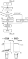
- Fig. 3 is a flowchart illustrating a main operation procedure of an example HUD device 10
- Fig. 4(a) and Fig. 4(b) are diagrams illustrating a display example of an image 75 corresponding to the flowchart of Fig. 3.
- Fig. 4(a) illustrates a display example of the image 75 in which step S13 in Fig. 3 is executed if a traffic light 200 is in a first lamp color state 210
- Fig. 4(b) illustrates a display example of the image 75 in which step S14 in Fig. 3 is executed if the traffic light 200 is in a second lamp color state 220.
- step S12 the display distance determination unit 31 determines whether the lamp color state acquired by the lamp color information acquisition unit 21 in step S11 is the first lamp color state 210 (red in the present example) or the second lamp color state 220 (green in the present example).
- step S13 the display distance determination unit 31 sets the display distance 100 of the image 75 to a first display distance 110, as illustrated in Fig. 4(a) , so that the projection unit 40 (stereoscopic image display unit 41) updates the display (step S15).
- step S14 the display distance determination unit 31 sets the display distance 100 of the image 75 to a second display distance 120, as illustrated in Fig. 4(b) , so that the projection unit 40 (stereoscopic image display unit 41) updates the display (step S15).
- the first display distance 110 is shorter than the second display distance 120.
- the image 75 displayed at the first display distance 110 is visually recognized closer to the vehicle 1 (the driver of the vehicle 1) than the image 75 displayed at the second display distance 120. Therefore, according to the HUD device 10, the display distance 100 of the image 75 is shorter (first display distance 110) or longer (second display distance 120) in accordance with the acquired lamp color state of the traffic light 200.
- the driver needs to adjust the focal distance of the eye 3 to visually recognize the image 75, and can guess the lamp color state of the traffic light 200 from the difference in the display distance 100 of the image 70 recognized by the movement of the focal distance of the eye 3.
- the image 70 includes an image indicating the lamp color state of the traffic light 200
- the image 70 does not include an image indicating the lamp color state of the traffic light 200
- Fig. 5 is a flowchart illustrating a main operation procedure of the HUD device 10 in a first embodiment
- Fig. 6(a) and Fig. 6(b) are diagrams illustrating a display example of the image 75 corresponding to the flowchart of Fig. 5.
- Fig. 6(a) illustrates a display example of the image 75 in which step S24 in Fig. 5 is executed if the traffic light 200 is in the first lamp color state 210
- Fig. 6(b) illustrates a display example of the image 75 in which step S25 in Fig. 5 is executed if the traffic light 200 is in the second lamp color state 220.
- the first embodiment differs from the above example in that: the first display distance 110 is visually recognized at a position closer than the traffic light 200 with the vehicle 1 as reference, and the second display distance 120 is visually recognized at a position farther than the traffic light 200 with the vehicle 1 as reference.
- step S21 of Fig. 5 the display control unit 30 continuously and/or intermittently acquires, via a distance information acquisition unit 22, a distance 130 between the vehicle 1 and the traffic light 200 which the vehicle is scheduled to pass.
- step S22 the display control unit 30 continuously and/or intermittently acquires, via the lamp color information acquisition unit 21, the lamp color state of the traffic light 200 which the vehicle is scheduled to pass.
- step S23 the display distance determination unit 31 determines whether the lamp color state acquired by the lamp color information acquisition unit 21 in step S11 is the first lamp color state 210 (red in the present embodiment) or the second lamp color state 220 (green in the present embodiment).
- the processing proceeds to step S25, and the display distance 100 of the image 75 is set to the second display distance 120, as illustrated in Fig. 6(b) , so that the projection unit 40 (stereoscopic image display unit 41) updates the display (step S26).
- the display distance determination unit 31 refers to the distance 130 between the traffic light 200 and the vehicle 1 acquired by the distance information acquisition unit 22 in step S21, and sets a predetermined distance longer than the distance 130 between the traffic light 200 and the vehicle 1 as the second display distance 120.
- the display distance determination unit 31 sets, as the second display distance 120 of the image 75, a distance in an area separated more from the vehicle 1 than the traffic light 200 in the real space coordinates and separated from the vehicle 1 by a predetermined distance, or a distance separated from the vehicle 1 by a predetermined distance with the traffic light 200 as reference in the real space coordinates.
- the driver needs to adjust the focal distance of the eyes to visually recognize the image 75, and the lamp color state of the traffic light 200 can be guessed from the difference in the display distance 100 of the image 70 recognized by the movement of the focal distance of the eyes.
- the image 70 includes an image indicating the lamp color state of the traffic light 200, it is possible for the driver to recognize the lamp color state of the traffic light 200 more reliably or more emphatically, based on different processes for change in color of the image or for change in the display distance 100 of the image 70.
- the display distance determination unit 31 refers to the distance between the traffic light 200 and the vehicle 1 acquired by the distance information acquisition unit 22 in step S21, and sets, as the first display distance 110 at which the image 70 is displayed, a position closer to the vehicle 1 by a predetermined distance D1 with the distance 130 of the traffic light 200 as a reference in the real space coordinates.
- the display distance determination unit 31 maintains setting of a first display distance 112 of the image 75 at a position closer to the vehicle 1 by the predetermined distance D1 with the distance 132 of the traffic light 200 as a reference. That is, if the traffic light 200 approaches, the image 75 is visually recognized so that the distance from the traffic light 200 is maintained constant in the real space coordinates.
- the lamp color information acquisition unit 21 acquires the first lamp color state 210 and the second lamp color state 220 of the traffic light 200.
- the lamp color information acquisition unit 21 may acquire only either one of the first lamp color state 210 and the second lamp color state 220. It is possible that the lamp color information acquisition unit 21 acquires only either one of the first lamp color state 210 and the second lamp color state 220 of the traffic light 200, and if the predetermined lamp color state cannot be acquired, the lamp color state can be determined to be the other lamp color state.
- the lamp color information acquisition unit 21 acquires the lamp color state of the traffic light 200 at the actual time.
- the lamp color information acquisition unit 21 may acquire the remaining time (modification example of the lamp color state) until the first lamp color state 210 or the second lamp color state 220 is reached, and the display distance determination unit 31 may determine the display distance 100 of the image 70 based on the remaining time (the lamp color state) until the first lamp color state 210 or the second lamp color state 220 is reached.
- the lamp color information acquisition unit 21 may acquire the time elapsed (modification example of the lamp color state) since the first lamp color state 210 or the second lamp color state 220 is reached, and the display distance determination unit 31 may determine the display distance 100 of the image 70 based on the time elapsed (the lamp color state) since the first lamp color state 210 or the second lamp color state 220 is reached.
Landscapes
- Engineering & Computer Science (AREA)
- Physics & Mathematics (AREA)
- General Physics & Mathematics (AREA)
- Mechanical Engineering (AREA)
- Transportation (AREA)
- Chemical & Material Sciences (AREA)
- Combustion & Propulsion (AREA)
- Theoretical Computer Science (AREA)
- Multimedia (AREA)
- Automation & Control Theory (AREA)
- Computer Hardware Design (AREA)
- Mathematical Physics (AREA)
- Human Computer Interaction (AREA)
- Optics & Photonics (AREA)
- Instrument Panels (AREA)
Description
- The present invention relates to a head-up display (HUD) device to be mounted on a vehicle.
- HUD devices enable a viewer (typically, a driver of a vehicle) to visually recognize an image superimposed on a foreground of the vehicle. As described above, the HUD devices display an image which is to present, to the viewer, information superimposed on the foreground, so that the viewer can recognize the information indicated by the image without largely shifting a line of sight from the foreground, and therefore, the HUD devices can reduce a burden due to a movement of the line of sight by the viewer and contribute to safe driving.
- In particular, an HUD device disclosed in
Patent Document 1 receives a lamp color state of a traffic light which a vehicle is scheduled to pass, and displays an image indicating the lamp color state of the traffic light, and thus, a user can easily recognize the lamp color state of the traffic light. -
Patent Document 2 discloses a vehicle driving assistance device equipped with a view field interception determining unit to determine whether a front view field of the driver of the vehicle is intercepted by another forward vehicle, an image acquiring unit to acquire an image including a frontal image of the vehicle ahead when the front view field is determined to be intercepted by the forward vehicle, a specific object recognition unit to recognize out of the acquired image the specific object which is not visible to the driver because of interception by the forward vehicle and which nevertheless the driver should recognize visually, an image reading unit to read a simplified image obtained by the simplification of the recognized specific object, and a head-up display indicating unit to indicate only the simplified image which is read out. -
- Patent Document 1:
Japanese Unexamined Patent Application Publication No. 2016-112984 - Patent Document 2:
Japanese Unexamined Patent Application Publication No. 2998-149786 - However, if the lamp color state is simply displayed as an image, an action performed by the user is eventually the same between an action of recognizing the lamp color state of a traffic light in a real scene and an action of recognizing the lamp color state in the image, and thus, the same burden is imposed on the driver for determining the lamp color state of the traffic light.
- One object of the present invention is to provide a head-up display device allowing for recognition of a lamp color state of a traffic light instead of or in addition to simply displaying a color image of the lamp color state of the traffic light.
- To solve the above-described problems, the present invention employs the following means.
- A head-up display device according to the present invention is capable of adjusting a display distance which is a distance to an image recognized by a viewer, , and its gist is to cause a lamp color state of a traffic light recognized from difference in the display distance by changing the display distance based on the lamp color state.
- A head-up display device according to a first aspect of the present invention includes: a projection unit (40) configured to project, towards a projected portion, display light (L) displaying an image (70) at a variable display distance (100) from a viewer; a lamp color information acquisition unit (21) configured to acquire a lamp color state (210, 220) of a traffic light which a vehicle is scheduled to pass; and a display distance adjustment unit (31) configured to change the display distance (100) of the image (70), based on the lamp color state acquired by the information acquisition unit (20); a distance information acquisition unit (22) configured to acquire a distance (130) to the traffic light of which the lamp color state is acquired by the lamp color information acquisition unit (21), and the display distance adjustment unit (31) refers to the distance (130) to the traffic light acquired by the distance information acquisition unit (22), and if the lamp color state acquired by the lamp color information acquisition unit (21) is a first lamp color state (210), the display distance adjustment unit (31) displays at least a part of the image (70) to be visually recognized in front of the traffic light, and if the lamp color state acquired by the lamp color information acquisition unit (21) is a second lamp color state (220), the display distance adjustment unit (31) displays at least a part of the image (70) to be visually recognized behind the traffic light.
- According to the first aspect, a display position (display distance) in a depth direction of the image to be visually recognized by the viewer can be adjusted to be near the viewer or far away from the viewer in accordance with the lamp color state of the traffic light. Thus, if the image includes an image indicating the lamp color state of the traffic light, it is possible for the viewer to recognize the lamp color state of the traffic light more reliably or more emphatically, based on different processes for change in color of the image indicating the lamp color state or for change in display distance of the image. Further, if the image does not include an image indicating the lamp color state of the traffic light, it is possible for the viewer to recognize the lamp color state of the traffic light more reliably or more emphatically, based on different processes for change in lamp color of the traffic light being a real object existing in the real scene or for change in display distance of the image.
- According to the first aspect, it is possible to switch the display position of the image between in front of and behind the traffic light in accordance with the lamp color state of the traffic light. Therefore, it is possible to guess the lamp color state of the traffic light depending on whether the image is displayed in front of or behind the traffic light, and thus, it is easier to clearly determine the lamp color state than in a case where the large display distance and the short display distance of the image are simply switched. It is noted that the distance between a near side and a far side of the display position of the image is preferably 5 [m] or more.
- Further, in the head-up display device according to a second aspect dependent on the first aspect, the first lamp color state (210) is red, and the second lamp color state (220) is green.
- In the second aspect, if the traffic light is red, an image is displayed in front of the traffic light, and thus, if the eye is focused on the image, the red traffic light is located farther away from a position on which the eye is focused. In general, the visibility on the far side from a position on which the eye is focused (focused position) is high, so that even if an image is visually recognized, attention can be easily directed to the red traffic light. Further, if the traffic light is green, the image is displayed behind the traffic light, and thus, if the eye is focused on the image, the green traffic light is located closer than a position on which the eye is focused. The visibility on the near side from the focused position is low, so that if an image is visually recognized, it is less likely that attention is directed to a green traffic light that requires little attention, and visual attention is less likely to be distracted.
- Further, in the head-up display device according to a third aspect dependent on the first or second aspect, if the display distance adjustment unit (31) displays at least a part of the image (70) to be visually recognized in front of the traffic light, the display distance adjustment unit (31) gradually reduces the display distance (100) as the distance to the traffic light acquired by the distance information acquisition unit (22) decreases.
- In the third aspect, as the distance to the traffic light decreases, the display distance is gradually reduced. In other words, the display distance of the image follows the position of the traffic light. Therefore, even if the traffic light gradually approaches, the distance between the traffic light and the image is constant or hardly changes, so that a focusing movement between the traffic light and the image can be facilitated. Further, when the image is arranged in front of the traffic light, as described in the third aspect, even if the image is visually recognized, it is likely that attention is directed to the traffic light behind the image, and it is possible to smoothly move the focus from the image to the traffic light behind the image.
- Further, in the head-up display device according to a fourth aspect dependent on the first to third aspects, if the display distance adjustment unit (31) displays at least a part of the image to be visually recognized behind the traffic light, the display distance adjustment unit (31) maintains the display distance (100) constant even if the distance to the traffic light acquired by the distance information acquisition unit (22) decreases.
- In the fourth aspect, the display distance is maintained constant regardless of the distance to the traffic light. In other words, the display distance of the image does not follow the position of the traffic light. Therefore, even if the traffic light gradually approaches, the distance between the vehicle and the image is constant, so that a focusing movement to the image can be facilitated, regardless of the position of the traffic light. Further, when the image is arranged behind the traffic light, as described in the third aspect, if the image is visually recognized, it is less likely that attention is directed to the traffic light in front of the image, however, since an interval between the position of the traffic light and the display distance of the image increases in accordance with the position of the traffic light, it is difficult to smoothly move the focus between the image and the traffic light in front of the image, so that it is even less likely that visual attention is directed to the traffic light.
-
-
Fig. 1 is a diagram for explaining a configuration of an HUD device and an image displayed by the HUD device. -
Fig. 2 is a diagram illustrating a configuration of a projection unit in the HUD device. -
Fig. 3 is a flowchart illustrating a main operation procedure of an example HUD device. -
Fig. 4(a) and Fig. 4(b) are diagrams each illustrating a display example of an image displayed by the example HUD device. -
Fig. 5 is a flowchart illustrating a main operation procedure of the HUD device in a first embodiment of the present invention. -
Fig. 6(a) and Fig. 6(b) are diagrams each illustrating a display example of an image displayed by an HUD device according to the first embodiment. -
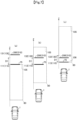
Fig. 7(a) to Fig. 7(c) are diagrams each illustrating a display example of an image displayed by an HUD device according to a second embodiment of the present invention. -
Fig. 8(a) to Fig. 8(c) are diagrams each illustrating a display example of an image displayed by an HUD device according to the third embodiment of the present invention. - Embodiments described below are employed to facilitate understanding of the present invention and those skilled in the art should note that the present invention is not limited by the embodiments described below, but rather by the appended claims.
-
Fig. 1 is a diagram for explaining a configuration corresponding to each of first to third embodiments of a head-up display (hereinafter, also referred to as HUD) device 10 according to the present invention and animage 70 displayed by the HUD device 10. It is noted that inFig. 1 , a front-rear direction of avehicle 1 is regarded as a Z direction (the front direction thereof is a positive Z direction), a direction along a left-right direction of the vehicle 1 (a width direction of the vehicle 1) is regarded as an X direction (the left direction thereof is a positive X direction), and an up-down direction is regarded as a Y direction (the upward direction thereof is a positive Y direction). - In
Fig. 1 , the HUD device 10 is communicably connected to acommunication interface 5. Thecommunication interface 5 may include a wired communication function such as a USB port, a serial port, a parallel port, an OBD II, and/or any other suitable wired communication port. A data cable from thevehicle 1 is connected to aninformation acquisition unit 20 of the HUD device 10 via thecommunication interface 5 to transmit information to the HUD device 10. Alternatively, thecommunication interface 5 may include a wireless communication interface using, for example, a Bluetooth (registered trademark) communication protocol, an IEEE 802.11 protocol, an IEEE 1002.11 protocol, an IEEE 1002.16 protocol, a Dedicated Short Range Communications (DSRC) protocol, a shared wireless access protocol, a wireless USB protocol, and/or any other suitable wireless technology. - The HUD device 10 includes the
information acquisition unit 20 being an input interface configured to acquire various types of information from thecommunication interface 5, a display control unit 30, and aprojection unit 40 configured to project display light L. For example, thecommunication interface 5 is connected with a vehicle ECU, a vehicle-mounted camera, and a sensor provided in thevehicle 1, another vehicle-mounted device in the vehicle, a portable device in the vehicle, another vehicle (vehicle-to-vehicle communication V2V), communication infrastructure on a road (road-to-vehicle communication V2I), a pedestrian portable device (communication V2X between a vehicle and a pedestrian), and the like, so that information can be received, and the HUD device 10 receives various types of information from theinformation acquisition unit 20 connected to thecommunication interface 5 and reflects the information on theimage 70 to be displayed. - The HUD device 10 projects the display light L toward a projected
portion 2 provided inside thevehicle 1 and configured to transmit a part of the light and reflect a part of the light. The projectedportion 2 may be configured as a part of a front windshield of thevehicle 1 or may be a dedicated part such as a combiner. Aneye box 4 is formed by the display light L reflected by the projectedportion 2 in an area where aneye 3 of a viewer (driver of the vehicle 1) is assumed to be placed. The driver can visually recognize theentire image 70 displayed by the HUD device 10 if theeye 3 is placed in theeye box 4, and the driver cannot visually recognize (cannot easily visually recognize) a part of theimage 70 if theeye 3 is out of theeye box 4. The HUD device 10 can adjust, in the X direction, in the Y direction, and in the Z direction, positions at whichimages display distance 100 being a distance in the depth direction Z, particularly from theeye box 4 to where theimages images image display area 80 being a three-dimensional space. - The display control unit 30 includes a display
distance determination unit 31 and a displaydata generation unit 32. The display control unit 30 generates display data, based on the information acquired from theinformation acquisition unit 20, and displays theimage 70 by driving theprojection unit 40, based on the display data. - The display
distance determination unit 31 determines the display distances 100 of theimage 70, and can determine the display distances 100 of the image 70 (specifically, of each of theimages information acquisition unit 20. Details will be described later. - The display
data generation unit 32 generates display data, and theprojection unit 40 is driven based on the display data. The display data includes display distance data for driving theprojection unit 40 to display theimage 70 at thedisplay distance 100 determined by the displaydistance determination unit 31. - An example of the
image 70 displayed by the HUD device 10 will be described with respect to a left-side part ofFig. 1 . Theimage 70 includes, for example, thefirst 2D image 71 and thesecond 2D image 72 which are represented in a planar manner, and the3D image 73 represented in a three-dimensional manner. Thefirst 2D image 71 is formed on an XY plane at adisplay distance 101 inFig. 1 in a planar manner, and does not enable the driver to feel a sense of perspective. The whole display of thefirst 2D image 71 thus formed can be clearly recognized, substantially without adjusting the focus of the eyes. Thesecond 2D image 72 has one end on the XY plane at adisplay distance 103 ofFig. 1 and the other end on the XY plane at adisplay distance 104 farther apart from the driver relative to thedisplay distance 103, and is formed in a planer manner and enables the driver to feel a sense of perspective. Thesecond 2D image 72 thus formed can give a three-dimensional impression because the whole display is clearly recognized if the focus of the eyes of the driver is adjusted. In an example of the3D image 73, the3D image 73 has one end on the XY plane at adisplay distance 102 inFig. 1 and the other end on the XY plane at thedisplay distance 103 farther apart from the driver relative to thedisplay distance 102, and is formed as a three-dimensional object having a volume and enables the driver to feel a three-dimensional effect. If lengthening thedisplay distance 100 is expressed in other words, it indicates forming theimage 70 at a position farther apart from theeye box 4, and for example, this means that thefirst 2D image 71 displayed at thedisplay distance 101 and the3D image 73 displayed between thedisplay distance 102 and thedisplay distance 103 are brought close to thedisplay distance 104 farther away from theeye box 4. On the other hand, if shortening thedisplay distance 100 is expressed in other words, it indicates forming theimage 70 at a position closer to theeye box 4, and for example, this means that thefirst 2D image 71 displayed at thedisplay distance 104 and the3D image 73 displayed between thedisplay distance 102 and thedisplay distance 103 are brought close to thedisplay distance 101 nearer theeye box 4. - Next, the description proceeds with reference to
Fig. 2. Fig. 2 is a diagram illustrating an example of a configuration of theprojection unit 40 inFig. 1 . Theprojection unit 40 includes a stereoscopicimage display unit 41 and relayoptical units 42, and the stereoscopicimage display unit 41 forms a first 3Dreal image 43, the relayoptical units 42 magnify the first 3Dreal image 43 to form a second 3Dreal image 44 and project the display light L of the second 3Dreal image 44 toward the projectedportion 2 outside. - The stereoscopic
image display unit 41 inFig. 2 generates the first 3Dreal image 43 formed in three dimensions, and includes animage projection unit 45 and a vibratingscreen 46. - The
image projection unit 45 is a projector configured to emit video light (not illustrated) representing a video included in display data, based on the display data input from the display control unit 30, adjusts a timing for displaying the video in accordance with display distance data included in the display data, and switches the video at high speed to project the video in synchronization with a vibration position of the vibratingscreen 46. In other words, based on the display distance data, theimage projection unit 45 projects the video suitable for the vibration position of the vibratingscreen 46, onto the vibratingscreen 46. - The vibrating
screen 46 is, for example, a diffusion film made of polycarbonate for diffusing video from theimage projection unit 45 into a certain angle range, receives the video light from theimage projection unit 45 to form a real image, and reciprocates along an optical axis of the video light emitted from theimage projection unit 45. The vibratingscreen 46 can continuously or intermittently transmit a signal indicating a vibration position to theimage projection unit 45, and theimage projection unit 45 may adjust the timing for displaying the video, based on the signal indicating the vibration position, so that theimage 70 is visually recognized at a position in accordance with the display distance data included in the display data. - The display control unit 30 adjusts a length in the depth direction Z of the
image 70 while maintaining constant an amplitude of the vibratingscreen 46 in a screen vibration direction. That is, the display control unit 30 does not emit the display light L in a period during which the vibratingscreen 46 is in a first range of the amplitude, and emits the display light L in a period during which the vibratingscreen 46 is in a second range of the amplitude. If a position and a ratio of the first range and the second range are adjusted, a position and a length in the depth direction Z of theimage 70 are adjusted. Specifically, the vibratingscreen 46 vibrates at a frequency of 60 [Hz] or more, and if theimage projection unit 45 projects different videos having a plurality of frames within theperiod 1/60 [sec], the different videos (real images) having a plurality of frames are formed at each of vibration positions. That is, if real images having a plurality of frames overlap in the vibration direction of the vibratingscreen 46, the first 3Dreal image 43 is generated. It is noted that the display control unit 30 may adjust the length of theimage 70 in the depth direction Z by changing the amplitude of the vibratingscreen 46. - The relay
optical units 42 inFig. 2 receive light of the first 3Dreal image 43 generated by the stereoscopicimage display unit 41, form the second 3Dreal image 44 obtained by magnifying the first 3Dreal image 43, between the relayoptical units 42, and then, project the display light L being light of the second 3Dreal image 44 toward the projectedportion 2. The relayoptical units 42 include, for example, a first relayoptical unit 47 including a group of lenses configured to receive the light of the first 3Dreal image 43 generated by the stereoscopicimage display unit 41, a second relayoptical unit 48 configured to reflect the light passing through the first relayoptical unit 47 and cooperate with an optical power of the first relayoptical unit 47 to form the second 3Dreal image 44 obtained by magnifying the first 3Dreal image 43, and a third relayoptical unit 49 configured to reflect the display light L being light of the second 3Dreal image 44, toward the projectedportion 2. - The first relay
optical unit 47 has a function of magnifying a video formed at each of vibration positions of the vibratingscreen 46 in the first 3Dreal image 43, with a different magnification, and although a single lens is illustrated inFig. 2 for simplicity, the first relayoptical unit 47 is actually configured of a composition lens obtained by combining a plurality of thin film lenses not illustrated. - The second relay
optical unit 48 includes, for example, a mirror having a concave reflection surface having a positive optical power, and receives the light of the first 3Dreal image 43 from the first relayoptical unit 47, reflects the received light toward the third relayoptical unit 49, and cooperates with the optical power of the first relayoptical unit 47 to form the second 3Dreal image 44 obtained by magnifying the first 3Dreal image 43 between the second relayoptical unit 48 and the third relayoptical unit 49. If the first relayoptical unit 47 has an optical function provided by the second relayoptical unit 48, the second relayoptical unit 48 may be omitted. - The third relay
optical unit 49 is a concave mirror configured to reflect the display light L of the second 3Dreal image 44 toward the projectedportion 2, and has a function of correcting an image distortion caused by a curved shape of the projectedportion 2 and a function of magnifying the second 3Dreal image 44. - Thus, the configuration of the
projection unit 40 configured to ensure that the3D image 70 is visually recognized is described, but the above is not limiting. Alternatives of theprojection unit 40 is described below. - In another embodiment causing a viewer visually recognized an image of which the display distance from the viewer is variable, the
projection unit 40 may employ known 3D display schemes, such as a parallax division scheme including a parallax barrier scheme and a lenticular lens scheme, a space reproduction scheme including a light field scheme and a hologram scheme, a transmittance adjustment screen scheme in which a plurality of screens having a light control layer whose transmittance can be adjusted are arranged in a stack in a thickness direction, a projector projects projection images, which are switched at high speed, toward the plurality of screens, and a 3D real image is displayed inside as a result of the plurality of screens appropriately adjusting respective dimming rates in response to the high-speed switching of the projection image, as disclosed inJapanese Patent Application Publication No. 2016-212318 Japanese Patent Application Publication No. 2004-168230 - The first to third embodiments will be described below in detail with reference to
Fig. 5 to Fig. 8 . - First, the description proceeds with reference to
Fig. 3, Fig. 4(a), and Fig. 4(b). Fig. 3 is a flowchart illustrating a main operation procedure of an example HUD device 10, andFig. 4(a) and Fig. 4(b) are diagrams illustrating a display example of animage 75 corresponding to the flowchart ofFig. 3. Fig. 4(a) illustrates a display example of theimage 75 in which step S13 inFig. 3 is executed if atraffic light 200 is in a firstlamp color state 210, andFig. 4(b) illustrates a display example of theimage 75 in which step S14 inFig. 3 is executed if thetraffic light 200 is in a secondlamp color state 220. - In step S11 of
Fig. 3 , the display control unit 30 continuously and/or intermittently acquires, via a lamp colorinformation acquisition unit 21, a lamp color state of a traffic light which the vehicle is scheduled to pass. - Subsequently, in step S12, the display
distance determination unit 31 determines whether the lamp color state acquired by the lamp colorinformation acquisition unit 21 in step S11 is the first lamp color state 210 (red in the present example) or the second lamp color state 220 (green in the present example). - If the
traffic light 200 is red (in the first lamp color state 210), the processing proceeds to step S13, and the displaydistance determination unit 31 sets thedisplay distance 100 of theimage 75 to afirst display distance 110, as illustrated inFig. 4(a) , so that the projection unit 40 (stereoscopic image display unit 41) updates the display (step S15). Further, if thetraffic light 200 is green (in the second lamp color state 220), the processing proceeds to step S14, and the displaydistance determination unit 31 sets thedisplay distance 100 of theimage 75 to asecond display distance 120, as illustrated inFig. 4(b) , so that the projection unit 40 (stereoscopic image display unit 41) updates the display (step S15). - In this case, the
first display distance 110 is shorter than thesecond display distance 120. In other words, theimage 75 displayed at thefirst display distance 110 is visually recognized closer to the vehicle 1 (the driver of the vehicle 1) than theimage 75 displayed at thesecond display distance 120. Therefore, according to the HUD device 10, thedisplay distance 100 of theimage 75 is shorter (first display distance 110) or longer (second display distance 120) in accordance with the acquired lamp color state of thetraffic light 200. The driver needs to adjust the focal distance of theeye 3 to visually recognize theimage 75, and can guess the lamp color state of thetraffic light 200 from the difference in thedisplay distance 100 of theimage 70 recognized by the movement of the focal distance of theeye 3. Thus, if theimage 70 includes an image indicating the lamp color state of thetraffic light 200, it is possible for the driver to recognize a lamp color state of thetraffic light 200 more reliably or more emphatically, based on different processes for change in color of the image or for change in thedisplay distance 100 of theimage 70. Further, if theimage 70 does not include an image indicating the lamp color state of thetraffic light 200, it is possible for the driver to recognize a lamp color state of thetraffic light 200 more reliably or more emphatically, based on different processes for change in lamp color of thetraffic light 200 being a real object existing in the real scene or for change in thedisplay distance 100 of theimage 70. - Next, the description proceeds with reference to
Fig. 5, Fig. 6(a), and Fig. 6(b). Fig. 5 is a flowchart illustrating a main operation procedure of the HUD device 10 in a first embodiment, andFig. 6(a) and Fig. 6(b) are diagrams illustrating a display example of theimage 75 corresponding to the flowchart ofFig. 5. Fig. 6(a) illustrates a display example of theimage 75 in which step S24 inFig. 5 is executed if thetraffic light 200 is in the firstlamp color state 210, andFig. 6(b) illustrates a display example of theimage 75 in which step S25 inFig. 5 is executed if thetraffic light 200 is in the secondlamp color state 220. The first embodiment differs from the above example in that: thefirst display distance 110 is visually recognized at a position closer than thetraffic light 200 with thevehicle 1 as reference, and thesecond display distance 120 is visually recognized at a position farther than thetraffic light 200 with thevehicle 1 as reference. - In step S21 of
Fig. 5 , the display control unit 30 continuously and/or intermittently acquires, via a distanceinformation acquisition unit 22, adistance 130 between thevehicle 1 and thetraffic light 200 which the vehicle is scheduled to pass. - Subsequently, in step S22, the display control unit 30 continuously and/or intermittently acquires, via the lamp color
information acquisition unit 21, the lamp color state of thetraffic light 200 which the vehicle is scheduled to pass. - Subsequently, in step S23, the display
distance determination unit 31 determines whether the lamp color state acquired by the lamp colorinformation acquisition unit 21 in step S11 is the first lamp color state 210 (red in the present embodiment) or the second lamp color state 220 (green in the present embodiment). - If the
traffic light 200 is red (in the first lamp color state 210), the processing proceeds to step S24, and the displaydistance determination unit 31 sets thedisplay distance 100 of theimage 75 to thefirst display distance 110, as illustrated inFig. 6(a) , so that the projection unit 40 (stereoscopic image display unit 41) updates the display (step S26). In the determination of thefirst display distance 110, the displaydistance determination unit 31 refers to thedistance 130 between thetraffic light 200 and thevehicle 1 acquired by the distanceinformation acquisition unit 22 in step S21, and sets a predetermined distance within thedistance 130 between thetraffic light 200 and thevehicle 1 as thefirst display distance 110 of theimage 70. Specifically, for example, the displaydistance determination unit 31 sets, as thefirst display distance 110 of theimage 75, the same distance as thedistance 130 between thetraffic light 200 and thevehicle 1, or a distance within an area closer to thevehicle 1 than thetraffic light 200 in real space coordinates and separated from thevehicle 1 by a predetermined distance, or a distance closer to thevehicle 1 by a predetermined distance with thetraffic light 200 as reference in the real space coordinates. - Further, if the
traffic light 200 is green (in the second lamp color state 220), the processing proceeds to step S25, and thedisplay distance 100 of theimage 75 is set to thesecond display distance 120, as illustrated inFig. 6(b) , so that the projection unit 40 (stereoscopic image display unit 41) updates the display (step S26). In the determination of thesecond display distance 120, the displaydistance determination unit 31 refers to thedistance 130 between thetraffic light 200 and thevehicle 1 acquired by the distanceinformation acquisition unit 22 in step S21, and sets a predetermined distance longer than thedistance 130 between thetraffic light 200 and thevehicle 1 as thesecond display distance 120. Specifically, for example, the displaydistance determination unit 31 sets, as thesecond display distance 120 of theimage 75, a distance in an area separated more from thevehicle 1 than thetraffic light 200 in the real space coordinates and separated from thevehicle 1 by a predetermined distance, or a distance separated from thevehicle 1 by a predetermined distance with thetraffic light 200 as reference in the real space coordinates. - In this case, the
first display distance 110 is shorter than thedistance 130 between thetraffic light 200 and thevehicle 1, and thesecond display distance 120 is longer than thedistance 130 between thetraffic light 200 and thevehicle 1. In other words, theimage 75 displayed at thefirst display distance 110 is visually recognized at the same distance as thetraffic light 200 or closer to thevehicle 1 than thetraffic light 200, and theimage 75 displayed at thesecond display distance 120 is visually recognized farther away from thevehicle 1 than thetraffic light 200. Therefore, according to the HUD device 10 of the present embodiment, thedisplay distance 100 of theimage 75 is closer than the traffic light 200 (first display distance 110) or farther than the traffic light 200 (second display distance 120) in accordance with the acquired lamp color state of thetraffic light 200. The driver needs to adjust the focal distance of the eyes to visually recognize theimage 75, and the lamp color state of thetraffic light 200 can be guessed from the difference in thedisplay distance 100 of theimage 70 recognized by the movement of the focal distance of the eyes. Thus, if theimage 70 includes an image indicating the lamp color state of thetraffic light 200, it is possible for the driver to recognize the lamp color state of thetraffic light 200 more reliably or more emphatically, based on different processes for change in color of the image or for change in thedisplay distance 100 of theimage 70. On the other hand, if theimage 70 does not include an image indicating the lamp color state of thetraffic light 200, it is possible for the driver to recognize the lamp color state of thetraffic light 200 more reliably or more emphatically, based on different processes for change in lamp color of thetraffic light 200 being a real object existing in the real scene or for change in thedisplay distance 100 of theimage 70. It is easier to clearly determine the lamp color state than in the above example where the displaydistance determination unit 31 simply switches between thelarge display distance 100 and thesmall display distance 100 of the image. The distance between the near side (first display distance 110) and the far side (second display distance 120) of thedisplay distance 100 of theimage 70 is preferably 5 [m] or more. - Next, the description proceeds with reference to
Fig. 7(a) to Fig. 7(c). Fig. 7(a) to Fig. 7(c) are diagrams each illustrating a display example of theimage 75 in which the process of step S24 inFig. 5 is executed, and illustrate a transition of the display of theimage 75 as thevehicle 1 gradually approaches thetraffic light 200. The displaydistance determination unit 31 according to the second embodiment sets thefirst display distance 110 at which theimage 75 is displayed so that theimage 75 is visually recognized at a position separated by a constant distance with thetraffic light 200 as reference in the real space coordinates. - In step S24 of
Fig. 5 , the displaydistance determination unit 31 according to the second embodiment refers to the distance between thetraffic light 200 and thevehicle 1 acquired by the distanceinformation acquisition unit 22 in step S21, and sets, as thefirst display distance 110 at which theimage 70 is displayed, a position closer to thevehicle 1 by a predetermined distance D1 with thedistance 130 of thetraffic light 200 as a reference in the real space coordinates. - Specifically, as illustrated in
Fig. 7(a) , if adistance 131 from thevehicle 1 to thetraffic light 200 is separated by the predetermined distance D1 or more from afirst distance 105 predetermined within theimage display area 80, the displaydistance determination unit 31 maintains the setting of afirst display distance 111 of theimage 75 as thefirst distance 105. That is, theimage 75 is displayed at the constantfirst distance 105 regardless of the position of thetraffic light 200. For example, as illustrated inFig. 7(a) , thefirst distance 105 is set at a position (end) farthest from thevehicle 1 in theimage display area 80, but is not limited thereto. Thefirst distance 105 may be set at a predetermined position within theimage display area 80. - Subsequently, as illustrated in
Fig. 7(b) , if the distance between adistance 132 from thevehicle 1 to thetraffic light 200 and thefirst distance 105 predetermined within theimage display area 80 is within the predetermined distance D1, or if thetraffic light 200 is closer than thefirst distance 105, the displaydistance determination unit 31 maintains setting of afirst display distance 112 of theimage 75 at a position closer to thevehicle 1 by the predetermined distance D1 with thedistance 132 of thetraffic light 200 as a reference. That is, if thetraffic light 200 approaches, theimage 75 is visually recognized so that the distance from thetraffic light 200 is maintained constant in the real space coordinates. - Subsequently, as illustrated in
Fig. 7(c) , if adistance 133 from thevehicle 1 to thetraffic light 200 is less than the predetermined distance D1 from asecond distance 106 predetermined within theimage display area 80, the displaydistance determination unit 31 maintains the setting of afirst display distance 113 of theimage 75 to thesecond distance 106. That is, theimage 75 is displayed at the constantsecond distance 106 regardless of the position of thetraffic light 200. For example, as illustrated inFig. 7(c) , thesecond distance 106 is set at a position (end) of theimage display area 80 closest to thevehicle 1, but is not limited thereto. Thesecond distance 106 may be set at a predetermined position within theimage display area 80. - To summarize the processing of the second embodiment illustrated in
Fig. 7(a) to Fig. 7(c) , (1) if thedistance 131 from thevehicle 1 to thetraffic light 200 is large (separated from the predeterminedfirst distance 105 by the distance D1 or more), the displaydistance determination unit 31 displays theimage 75 at the constantfirst distance 105 regardless of the position of thetraffic light 200. (2) If thedistance 133 from thevehicle 1 to thetraffic light 200 is short (less than the distance D1 from the predetermined second distance 106), the displaydistance determination unit 31 displays theimage 75 at the constantsecond distance 106 regardless of the position of thetraffic light 200. (3) If thedistance 132 from thevehicle 1 to thetraffic light 200 is within a predetermined range (the range less than the sum of thefirst distance 105 and the distance D1, and equal to or more than the sum of thesecond distance 106 and the distance D1), the displaydistance determination unit 31 displays theimage 75 in accordance with the position of thetraffic light 200, so that the distance from thetraffic light 200 is maintained constant in the real space coordinates. Thus, the distance between thetraffic light 200 and theimage 75 can be maintained constant during the display, and visual attention can be easily directed both to the display content of theimage 75 and thetraffic light 200. Further, theimage 75 changes in accordance with the position of thetraffic light 200, and thus, the approaching of thetraffic light 200 can be recognized by visually recognizing theimage 75. - Next, the description proceeds with reference to
Fig. 8(a) to Fig. 8(c). Fig. 8(a) to Fig. 8(c) are diagrams each illustrating a display example of theimage 75 in which the process of step S25 inFig. 5 is executed, and illustrate a transition of the display of theimage 75 as thevehicle 1 gradually approaches thetraffic light 200. The displaydistance determination unit 31 according to the third embodiment maintains the setting of theimage 75 to the predeterminedsecond display distance 120 regardless of the position of thetraffic light 200. - In step S25 of
Fig. 5 , the displaydistance determination unit 31 of the third embodiment displays theimage 70 at a predeterminedsecond display distance 121 regardless of thedistances traffic light 200. It is noted that thesecond display distance 120 is set to a position farther from thevehicle 1 than thedistance 130 of thetraffic light 200, however, if thetraffic light 200 is located at a position farther separated from the image display area 80 (for example, as illustrated inFig. 8(a) ), thesecond display distance 120 at which theimage 70 is displayed may be exceptionally set at a position closer to thevehicle 1 than thedistance 130 of thetraffic light 200. - Accordingly, if the lamp color state of the
traffic light 200 is the secondlamp color state 220, thesecond display distance 121 at which theimage 75 is displayed is maintained constant during the display, regardless of the position of thetraffic light 200, so that the display content of theimage 75 can be easily recognized, and it is possible to make it less likely that visual attention is directed to thetraffic light 200 from theimage 75. - It is noted that the present invention is not limited to the above embodiments and drawings, but is defined by the claims.
- In the embodiments described above, the lamp color
information acquisition unit 21 acquires the firstlamp color state 210 and the secondlamp color state 220 of thetraffic light 200. However, the lamp colorinformation acquisition unit 21 may acquire only either one of the firstlamp color state 210 and the secondlamp color state 220. It is possible that the lamp colorinformation acquisition unit 21 acquires only either one of the firstlamp color state 210 and the secondlamp color state 220 of thetraffic light 200, and if the predetermined lamp color state cannot be acquired, the lamp color state can be determined to be the other lamp color state. - Further, in the embodiments described above, the lamp color
information acquisition unit 21 acquires the lamp color state of thetraffic light 200 at the actual time. However, the lamp colorinformation acquisition unit 21 may acquire the remaining time (modification example of the lamp color state) until the firstlamp color state 210 or the secondlamp color state 220 is reached, and the displaydistance determination unit 31 may determine thedisplay distance 100 of theimage 70 based on the remaining time (the lamp color state) until the firstlamp color state 210 or the secondlamp color state 220 is reached. Further, the lamp colorinformation acquisition unit 21 may acquire the time elapsed (modification example of the lamp color state) since the firstlamp color state 210 or the secondlamp color state 220 is reached, and the displaydistance determination unit 31 may determine thedisplay distance 100 of theimage 70 based on the time elapsed (the lamp color state) since the firstlamp color state 210 or the secondlamp color state 220 is reached. -
- 1
- Vehicle
- 2
- Projected portion
- 3
- Eye
- 4
- Eye box
- 5
- Communication interface
- 10
- HUD device (head-up display device)
- 20
- Information acquisition unit
- 21
- lamp color information acquisition unit
- 22
- Distance information acquisition unit
- 30
- Display control unit
- 31
- Display distance determination unit
- 32
- Display data generation unit
- 40
- Projection unit
- 70
- Image
- 71
- First 2D image
- 72
- Second 2D image
- 73
- 3D image
- 75
- Image
- 80
- Image display area
- 200
- Traffic light
- 210
- First lamp color state
- 220
- Second lamp color state
- D1
- Distance
- L
- Display light
Claims (4)
- A head-up display device, comprising:a projection unit (40) configured to project, towards a projected portion, display light (L) displaying an image (70) at a variable display distance (100) from a viewer;a lamp color information acquisition unit (21) configured to acquire a lamp color state (210, 220) of a traffic light which a vehicle is scheduled to pass; anda display distance adjustment unit (31) configured to change the display distance (100) of the image (70), based on the lamp color state acquired by the information acquisition unit (20);a distance information acquisition unit (22) configured to acquire a distance (130) to the traffic light of which the lamp color state is acquired by the lamp color information acquisition unit (21), whereinthe display distance adjustment unit (31) refers to the distance (130) to the traffic light acquired by the distance information acquisition unit (22), and if the lamp color state acquired by the lamp color information acquisition unit (21) is a first lamp color state (210), the display distance adjustment unit (31) displays at least a part of the image (70) to be visually recognized in front of the traffic light, and if the lamp color state acquired by the lamp color information acquisition unit (21) is a second lamp color state (220), the display distance adjustment unit (31) displays at least a part of the image (70) to be visually recognized behind the traffic light.
- The head-up display device according to claim 1, wherein the first lamp color state (210) is red, and the second lamp color state (220) is green.
- The head-up display device according to claim 1 or 2, wherein if the display distance adjustment unit (31) displays at least a part of the image (70) to be visually recognized in front of the traffic light, the display distance adjustment unit (31) gradually reduces the display distance (100) as the distance to the traffic light acquired by the distance information acquisition unit (22) decreases.
- The head-up display device according to any one of claims 1 to 3, wherein if the display distance adjustment unit (31) displays at least a part of the image to be visually recognized behind the traffic light, the display distance adjustment unit (31) maintains the display distance (100) constant even if the distance to the traffic light acquired by the distance information acquisition unit (22) decreases.
Applications Claiming Priority (2)
| Application Number | Priority Date | Filing Date | Title |
|---|---|---|---|
| JP2017231176 | 2017-11-30 | ||
| PCT/JP2018/043319 WO2019107295A1 (en) | 2017-11-30 | 2018-11-26 | Head-up display device |
Publications (3)
| Publication Number | Publication Date |
|---|---|
| EP3718809A1 EP3718809A1 (en) | 2020-10-07 |
| EP3718809A4 EP3718809A4 (en) | 2021-08-25 |
| EP3718809B1 true EP3718809B1 (en) | 2023-12-27 |
Family
ID=66665094
Family Applications (1)
| Application Number | Title | Priority Date | Filing Date |
|---|---|---|---|
| EP18882674.7A Active EP3718809B1 (en) | 2017-11-30 | 2018-11-26 | Head-up display device |
Country Status (4)
| Country | Link |
|---|---|
| US (1) | US11538334B2 (en) |
| EP (1) | EP3718809B1 (en) |
| JP (1) | JP7173042B2 (en) |
| WO (1) | WO2019107295A1 (en) |
Families Citing this family (5)
| Publication number | Priority date | Publication date | Assignee | Title |
|---|---|---|---|---|
| JP7344635B2 (en) * | 2018-09-05 | 2023-09-14 | マクセル株式会社 | heads up display device |
| JP7268497B2 (en) * | 2019-06-24 | 2023-05-08 | トヨタ自動車株式会社 | signal recognition system |
| CN113759564B (en) * | 2020-06-04 | 2025-10-10 | 浙江棱镜全息科技有限公司 | Air imaging device for automobiles and human-computer interaction vehicle assistance system |
| US11610485B2 (en) * | 2021-01-26 | 2023-03-21 | GM Global Technology Operations LLC | Traffic signal change visualization systems and methods |
| CN112977469A (en) * | 2021-03-12 | 2021-06-18 | 乐视致新信息技术(武汉)有限公司 | Navigation device based on vehicle-mounted holographic projection and control method thereof |
Family Cites Families (10)
| Publication number | Priority date | Publication date | Assignee | Title |
|---|---|---|---|---|
| JP2004168230A (en) | 2002-11-21 | 2004-06-17 | Nissan Motor Co Ltd | Display device for vehicles |
| JP4807263B2 (en) * | 2006-09-14 | 2011-11-02 | トヨタ自動車株式会社 | Vehicle display device |
| JP2008149786A (en) * | 2006-12-14 | 2008-07-03 | Mazda Motor Corp | Vehicle driving support device and vehicle driving support system |
| EP1975675B1 (en) | 2007-03-29 | 2016-04-27 | GM Global Technology Operations LLC | Holographic information display |
| WO2009157108A1 (en) * | 2008-06-25 | 2009-12-30 | トヨタ自動車株式会社 | Driving support apparatus |
| JP2014235550A (en) * | 2013-05-31 | 2014-12-15 | 日本精機株式会社 | On-vehicle device |
| JP6184515B2 (en) * | 2013-11-18 | 2017-08-23 | 三菱電機株式会社 | Driving support device and driving support method |
| JP2016112984A (en) | 2014-12-12 | 2016-06-23 | 日本精機株式会社 | Virtual image display system for vehicle, and head up display |
| JP2016212318A (en) | 2015-05-12 | 2016-12-15 | カルソニックカンセイ株式会社 | Display and head-up display device |
| KR102102761B1 (en) * | 2017-01-17 | 2020-04-21 | 엘지전자 주식회사 | User interface apparatus for vehicle and Vehicle |
-
2018
- 2018-11-26 JP JP2019557209A patent/JP7173042B2/en active Active
- 2018-11-26 EP EP18882674.7A patent/EP3718809B1/en active Active
- 2018-11-26 US US16/762,060 patent/US11538334B2/en active Active
- 2018-11-26 WO PCT/JP2018/043319 patent/WO2019107295A1/en not_active Ceased
Also Published As
| Publication number | Publication date |
|---|---|
| US20200269692A1 (en) | 2020-08-27 |
| JP7173042B2 (en) | 2022-11-16 |
| JPWO2019107295A1 (en) | 2020-12-24 |
| WO2019107295A1 (en) | 2019-06-06 |
| EP3718809A1 (en) | 2020-10-07 |
| US11538334B2 (en) | 2022-12-27 |
| EP3718809A4 (en) | 2021-08-25 |
Similar Documents
| Publication | Publication Date | Title |
|---|---|---|
| EP3718809B1 (en) | Head-up display device | |
| EP3015904B1 (en) | Head-up display device | |
| EP3245550B1 (en) | Dual head-up display apparatus | |
| EP3015905B1 (en) | Head-up display device | |
| US9678341B2 (en) | Head-up display apparatus | |
| EP3026483A1 (en) | Head-up display device | |
| JP2010072455A (en) | In-vehicle display and display method | |
| EP3961353B1 (en) | Method and apparatus for controlling head-up display based on eye tracking status | |
| JP7033252B2 (en) | Head-up display | |
| JP6102628B2 (en) | Head-up display device | |
| JP2019127065A (en) | Display control device, and head-up display device | |
| JP2018193016A (en) | Head-up display device | |
| JP2018197008A (en) | Head-up display device | |
| JP2018202927A (en) | Head-up display device | |
| WO2018216552A1 (en) | Head-up display device | |
| US11187910B2 (en) | Head-up display device for adjusting display distances of virtual images | |
| JP2018207207A (en) | Head-up display device | |
| JP6829820B2 (en) | Head-up display device | |
| KR20220025625A (en) | Method and apparatus for controlling hud considering eye tracking status | |
| JP2019081478A (en) | Head-up display device | |
| JP2020106590A (en) | Display control device and head-up display device | |
| JP2018205401A (en) | Head-up display device | |
| JP2019055676A (en) | Display device for vehicle |
Legal Events
| Date | Code | Title | Description |
|---|---|---|---|
| STAA | Information on the status of an ep patent application or granted ep patent |
Free format text: STATUS: THE INTERNATIONAL PUBLICATION HAS BEEN MADE |
|
| PUAI | Public reference made under article 153(3) epc to a published international application that has entered the european phase |
Free format text: ORIGINAL CODE: 0009012 |
|
| STAA | Information on the status of an ep patent application or granted ep patent |
Free format text: STATUS: REQUEST FOR EXAMINATION WAS MADE |
|
| 17P | Request for examination filed |
Effective date: 20200427 |
|
| AK | Designated contracting states |
Kind code of ref document: A1 Designated state(s): AL AT BE BG CH CY CZ DE DK EE ES FI FR GB GR HR HU IE IS IT LI LT LU LV MC MK MT NL NO PL PT RO RS SE SI SK SM TR |
|
| AX | Request for extension of the european patent |
Extension state: BA ME |
|
| DAV | Request for validation of the european patent (deleted) | ||
| DAX | Request for extension of the european patent (deleted) | ||
| A4 | Supplementary search report drawn up and despatched |
Effective date: 20210722 |
|
| RIC1 | Information provided on ipc code assigned before grant |
Ipc: B60K 35/00 20060101AFI20210716BHEP Ipc: G02B 27/01 20060101ALI20210716BHEP Ipc: G08G 1/09 20060101ALI20210716BHEP Ipc: G09G 5/00 20060101ALI20210716BHEP Ipc: G09G 5/38 20060101ALI20210716BHEP |
|
| RIC1 | Information provided on ipc code assigned before grant |
Ipc: G09G 5/38 20060101ALI20230810BHEP Ipc: G09G 5/00 20060101ALI20230810BHEP Ipc: G08G 1/09 20060101ALI20230810BHEP Ipc: G02B 27/01 20060101ALI20230810BHEP Ipc: B60K 35/00 20060101AFI20230810BHEP |
|
| GRAP | Despatch of communication of intention to grant a patent |
Free format text: ORIGINAL CODE: EPIDOSNIGR1 |
|
| STAA | Information on the status of an ep patent application or granted ep patent |
Free format text: STATUS: GRANT OF PATENT IS INTENDED |
|
| INTG | Intention to grant announced |
Effective date: 20230927 |
|
| GRAS | Grant fee paid |
Free format text: ORIGINAL CODE: EPIDOSNIGR3 |
|
| GRAA | (expected) grant |
Free format text: ORIGINAL CODE: 0009210 |
|
| STAA | Information on the status of an ep patent application or granted ep patent |
Free format text: STATUS: THE PATENT HAS BEEN GRANTED |
|
| AK | Designated contracting states |
Kind code of ref document: B1 Designated state(s): AL AT BE BG CH CY CZ DE DK EE ES FI FR GB GR HR HU IE IS IT LI LT LU LV MC MK MT NL NO PL PT RO RS SE SI SK SM TR |
|
| REG | Reference to a national code |
Ref country code: GB Ref legal event code: FG4D |
|
| REG | Reference to a national code |
Ref country code: CH Ref legal event code: EP |
|
| REG | Reference to a national code |
Ref country code: DE Ref legal event code: R096 Ref document number: 602018063417 Country of ref document: DE |
|
| REG | Reference to a national code |
Ref country code: IE Ref legal event code: FG4D |
|
| PG25 | Lapsed in a contracting state [announced via postgrant information from national office to epo] |
Ref country code: GR Free format text: LAPSE BECAUSE OF FAILURE TO SUBMIT A TRANSLATION OF THE DESCRIPTION OR TO PAY THE FEE WITHIN THE PRESCRIBED TIME-LIMIT Effective date: 20240328 |
|
| REG | Reference to a national code |
Ref country code: LT Ref legal event code: MG9D |
|
| PG25 | Lapsed in a contracting state [announced via postgrant information from national office to epo] |
Ref country code: LT Free format text: LAPSE BECAUSE OF FAILURE TO SUBMIT A TRANSLATION OF THE DESCRIPTION OR TO PAY THE FEE WITHIN THE PRESCRIBED TIME-LIMIT Effective date: 20231227 |
|
| PG25 | Lapsed in a contracting state [announced via postgrant information from national office to epo] |
Ref country code: ES Free format text: LAPSE BECAUSE OF FAILURE TO SUBMIT A TRANSLATION OF THE DESCRIPTION OR TO PAY THE FEE WITHIN THE PRESCRIBED TIME-LIMIT Effective date: 20231227 |
|
| PG25 | Lapsed in a contracting state [announced via postgrant information from national office to epo] |
Ref country code: LT Free format text: LAPSE BECAUSE OF FAILURE TO SUBMIT A TRANSLATION OF THE DESCRIPTION OR TO PAY THE FEE WITHIN THE PRESCRIBED TIME-LIMIT Effective date: 20231227 Ref country code: GR Free format text: LAPSE BECAUSE OF FAILURE TO SUBMIT A TRANSLATION OF THE DESCRIPTION OR TO PAY THE FEE WITHIN THE PRESCRIBED TIME-LIMIT Effective date: 20240328 Ref country code: FI Free format text: LAPSE BECAUSE OF FAILURE TO SUBMIT A TRANSLATION OF THE DESCRIPTION OR TO PAY THE FEE WITHIN THE PRESCRIBED TIME-LIMIT Effective date: 20231227 Ref country code: ES Free format text: LAPSE BECAUSE OF FAILURE TO SUBMIT A TRANSLATION OF THE DESCRIPTION OR TO PAY THE FEE WITHIN THE PRESCRIBED TIME-LIMIT Effective date: 20231227 Ref country code: BG Free format text: LAPSE BECAUSE OF FAILURE TO SUBMIT A TRANSLATION OF THE DESCRIPTION OR TO PAY THE FEE WITHIN THE PRESCRIBED TIME-LIMIT Effective date: 20240327 |
|
| REG | Reference to a national code |
Ref country code: NL Ref legal event code: MP Effective date: 20231227 |
|
| REG | Reference to a national code |
Ref country code: AT Ref legal event code: MK05 Ref document number: 1644214 Country of ref document: AT Kind code of ref document: T Effective date: 20231227 |
|
| PG25 | Lapsed in a contracting state [announced via postgrant information from national office to epo] |
Ref country code: NL Free format text: LAPSE BECAUSE OF FAILURE TO SUBMIT A TRANSLATION OF THE DESCRIPTION OR TO PAY THE FEE WITHIN THE PRESCRIBED TIME-LIMIT Effective date: 20231227 |
|
| PG25 | Lapsed in a contracting state [announced via postgrant information from national office to epo] |
Ref country code: SE Free format text: LAPSE BECAUSE OF FAILURE TO SUBMIT A TRANSLATION OF THE DESCRIPTION OR TO PAY THE FEE WITHIN THE PRESCRIBED TIME-LIMIT Effective date: 20231227 Ref country code: RS Free format text: LAPSE BECAUSE OF FAILURE TO SUBMIT A TRANSLATION OF THE DESCRIPTION OR TO PAY THE FEE WITHIN THE PRESCRIBED TIME-LIMIT Effective date: 20231227 Ref country code: NO Free format text: LAPSE BECAUSE OF FAILURE TO SUBMIT A TRANSLATION OF THE DESCRIPTION OR TO PAY THE FEE WITHIN THE PRESCRIBED TIME-LIMIT Effective date: 20240327 Ref country code: NL Free format text: LAPSE BECAUSE OF FAILURE TO SUBMIT A TRANSLATION OF THE DESCRIPTION OR TO PAY THE FEE WITHIN THE PRESCRIBED TIME-LIMIT Effective date: 20231227 Ref country code: LV Free format text: LAPSE BECAUSE OF FAILURE TO SUBMIT A TRANSLATION OF THE DESCRIPTION OR TO PAY THE FEE WITHIN THE PRESCRIBED TIME-LIMIT Effective date: 20231227 Ref country code: HR Free format text: LAPSE BECAUSE OF FAILURE TO SUBMIT A TRANSLATION OF THE DESCRIPTION OR TO PAY THE FEE WITHIN THE PRESCRIBED TIME-LIMIT Effective date: 20231227 |
|
| PG25 | Lapsed in a contracting state [announced via postgrant information from national office to epo] |
Ref country code: IS Free format text: LAPSE BECAUSE OF FAILURE TO SUBMIT A TRANSLATION OF THE DESCRIPTION OR TO PAY THE FEE WITHIN THE PRESCRIBED TIME-LIMIT Effective date: 20240427 |
|
| PG25 | Lapsed in a contracting state [announced via postgrant information from national office to epo] |
Ref country code: AT Free format text: LAPSE BECAUSE OF FAILURE TO SUBMIT A TRANSLATION OF THE DESCRIPTION OR TO PAY THE FEE WITHIN THE PRESCRIBED TIME-LIMIT Effective date: 20231227 Ref country code: CZ Free format text: LAPSE BECAUSE OF FAILURE TO SUBMIT A TRANSLATION OF THE DESCRIPTION OR TO PAY THE FEE WITHIN THE PRESCRIBED TIME-LIMIT Effective date: 20231227 |
|
| PG25 | Lapsed in a contracting state [announced via postgrant information from national office to epo] |
Ref country code: SK Free format text: LAPSE BECAUSE OF FAILURE TO SUBMIT A TRANSLATION OF THE DESCRIPTION OR TO PAY THE FEE WITHIN THE PRESCRIBED TIME-LIMIT Effective date: 20231227 |
|
| PG25 | Lapsed in a contracting state [announced via postgrant information from national office to epo] |
Ref country code: SM Free format text: LAPSE BECAUSE OF FAILURE TO SUBMIT A TRANSLATION OF THE DESCRIPTION OR TO PAY THE FEE WITHIN THE PRESCRIBED TIME-LIMIT Effective date: 20231227 Ref country code: SK Free format text: LAPSE BECAUSE OF FAILURE TO SUBMIT A TRANSLATION OF THE DESCRIPTION OR TO PAY THE FEE WITHIN THE PRESCRIBED TIME-LIMIT Effective date: 20231227 Ref country code: RO Free format text: LAPSE BECAUSE OF FAILURE TO SUBMIT A TRANSLATION OF THE DESCRIPTION OR TO PAY THE FEE WITHIN THE PRESCRIBED TIME-LIMIT Effective date: 20231227 Ref country code: IT Free format text: LAPSE BECAUSE OF FAILURE TO SUBMIT A TRANSLATION OF THE DESCRIPTION OR TO PAY THE FEE WITHIN THE PRESCRIBED TIME-LIMIT Effective date: 20231227 Ref country code: IS Free format text: LAPSE BECAUSE OF FAILURE TO SUBMIT A TRANSLATION OF THE DESCRIPTION OR TO PAY THE FEE WITHIN THE PRESCRIBED TIME-LIMIT Effective date: 20240427 Ref country code: EE Free format text: LAPSE BECAUSE OF FAILURE TO SUBMIT A TRANSLATION OF THE DESCRIPTION OR TO PAY THE FEE WITHIN THE PRESCRIBED TIME-LIMIT Effective date: 20231227 Ref country code: CZ Free format text: LAPSE BECAUSE OF FAILURE TO SUBMIT A TRANSLATION OF THE DESCRIPTION OR TO PAY THE FEE WITHIN THE PRESCRIBED TIME-LIMIT Effective date: 20231227 Ref country code: AT Free format text: LAPSE BECAUSE OF FAILURE TO SUBMIT A TRANSLATION OF THE DESCRIPTION OR TO PAY THE FEE WITHIN THE PRESCRIBED TIME-LIMIT Effective date: 20231227 |
|
| PG25 | Lapsed in a contracting state [announced via postgrant information from national office to epo] |
Ref country code: PL Free format text: LAPSE BECAUSE OF FAILURE TO SUBMIT A TRANSLATION OF THE DESCRIPTION OR TO PAY THE FEE WITHIN THE PRESCRIBED TIME-LIMIT Effective date: 20231227 Ref country code: PT Free format text: LAPSE BECAUSE OF FAILURE TO SUBMIT A TRANSLATION OF THE DESCRIPTION OR TO PAY THE FEE WITHIN THE PRESCRIBED TIME-LIMIT Effective date: 20240429 |
|
| PG25 | Lapsed in a contracting state [announced via postgrant information from national office to epo] |
Ref country code: PT Free format text: LAPSE BECAUSE OF FAILURE TO SUBMIT A TRANSLATION OF THE DESCRIPTION OR TO PAY THE FEE WITHIN THE PRESCRIBED TIME-LIMIT Effective date: 20240429 Ref country code: PL Free format text: LAPSE BECAUSE OF FAILURE TO SUBMIT A TRANSLATION OF THE DESCRIPTION OR TO PAY THE FEE WITHIN THE PRESCRIBED TIME-LIMIT Effective date: 20231227 |
|
| REG | Reference to a national code |
Ref country code: DE Ref legal event code: R097 Ref document number: 602018063417 Country of ref document: DE |
|
| PG25 | Lapsed in a contracting state [announced via postgrant information from national office to epo] |
Ref country code: DK Free format text: LAPSE BECAUSE OF FAILURE TO SUBMIT A TRANSLATION OF THE DESCRIPTION OR TO PAY THE FEE WITHIN THE PRESCRIBED TIME-LIMIT Effective date: 20231227 |
|
| PG25 | Lapsed in a contracting state [announced via postgrant information from national office to epo] |
Ref country code: DK Free format text: LAPSE BECAUSE OF FAILURE TO SUBMIT A TRANSLATION OF THE DESCRIPTION OR TO PAY THE FEE WITHIN THE PRESCRIBED TIME-LIMIT Effective date: 20231227 |
|
| PLBE | No opposition filed within time limit |
Free format text: ORIGINAL CODE: 0009261 |
|
| STAA | Information on the status of an ep patent application or granted ep patent |
Free format text: STATUS: NO OPPOSITION FILED WITHIN TIME LIMIT |
|
| 26N | No opposition filed |
Effective date: 20240930 |
|
| PG25 | Lapsed in a contracting state [announced via postgrant information from national office to epo] |
Ref country code: SI Free format text: LAPSE BECAUSE OF FAILURE TO SUBMIT A TRANSLATION OF THE DESCRIPTION OR TO PAY THE FEE WITHIN THE PRESCRIBED TIME-LIMIT Effective date: 20231227 |
|
| REG | Reference to a national code |
Ref country code: CH Ref legal event code: PL |
|
| PG25 | Lapsed in a contracting state [announced via postgrant information from national office to epo] |
Ref country code: MC Free format text: LAPSE BECAUSE OF FAILURE TO SUBMIT A TRANSLATION OF THE DESCRIPTION OR TO PAY THE FEE WITHIN THE PRESCRIBED TIME-LIMIT Effective date: 20231227 |
|
| PG25 | Lapsed in a contracting state [announced via postgrant information from national office to epo] |
Ref country code: LU Free format text: LAPSE BECAUSE OF NON-PAYMENT OF DUE FEES Effective date: 20241126 |
|
| REG | Reference to a national code |
Ref country code: CH Ref legal event code: PL |
|
| GBPC | Gb: european patent ceased through non-payment of renewal fee |
Effective date: 20241126 |
|
| PG25 | Lapsed in a contracting state [announced via postgrant information from national office to epo] |
Ref country code: CH Free format text: LAPSE BECAUSE OF NON-PAYMENT OF DUE FEES Effective date: 20241130 |
|
| REG | Reference to a national code |
Ref country code: BE Ref legal event code: MM Effective date: 20241130 |
|
| PG25 | Lapsed in a contracting state [announced via postgrant information from national office to epo] |
Ref country code: GB Free format text: LAPSE BECAUSE OF NON-PAYMENT OF DUE FEES Effective date: 20241126 Ref country code: BE Free format text: LAPSE BECAUSE OF NON-PAYMENT OF DUE FEES Effective date: 20241130 |
|
| PG25 | Lapsed in a contracting state [announced via postgrant information from national office to epo] |
Ref country code: FR Free format text: LAPSE BECAUSE OF NON-PAYMENT OF DUE FEES Effective date: 20241130 |
|
| PG25 | Lapsed in a contracting state [announced via postgrant information from national office to epo] |
Ref country code: IE Free format text: LAPSE BECAUSE OF NON-PAYMENT OF DUE FEES Effective date: 20241126 |
|
| PGFP | Annual fee paid to national office [announced via postgrant information from national office to epo] |
Ref country code: DE Payment date: 20250930 Year of fee payment: 8 |
|
| PG25 | Lapsed in a contracting state [announced via postgrant information from national office to epo] |
Ref country code: HU Free format text: LAPSE BECAUSE OF FAILURE TO SUBMIT A TRANSLATION OF THE DESCRIPTION OR TO PAY THE FEE WITHIN THE PRESCRIBED TIME-LIMIT; INVALID AB INITIO Effective date: 20181126 |
|
| PG25 | Lapsed in a contracting state [announced via postgrant information from national office to epo] |
Ref country code: CY Free format text: LAPSE BECAUSE OF FAILURE TO SUBMIT A TRANSLATION OF THE DESCRIPTION OR TO PAY THE FEE WITHIN THE PRESCRIBED TIME-LIMIT; INVALID AB INITIO Effective date: 20181126 |