EP3718803A1 - Electric vehicle - Google Patents
Electric vehicle Download PDFInfo
- Publication number
- EP3718803A1 EP3718803A1 EP20165153.6A EP20165153A EP3718803A1 EP 3718803 A1 EP3718803 A1 EP 3718803A1 EP 20165153 A EP20165153 A EP 20165153A EP 3718803 A1 EP3718803 A1 EP 3718803A1
- Authority
- EP
- European Patent Office
- Prior art keywords
- brake
- vehicle
- storage chamber
- fluid pressure
- unit
- Prior art date
- Legal status (The legal status is an assumption and is not a legal conclusion. Google has not performed a legal analysis and makes no representation as to the accuracy of the status listed.)
- Granted
Links
- 239000012530 fluid Substances 0.000 claims abstract description 149
- 238000004378 air conditioning Methods 0.000 claims abstract description 22
- 108010066278 cabin-4 Proteins 0.000 description 37
- 230000007257 malfunction Effects 0.000 description 9
- 238000012423 maintenance Methods 0.000 description 8
- 230000005540 biological transmission Effects 0.000 description 2
- 238000004891 communication Methods 0.000 description 2
- 239000000470 constituent Substances 0.000 description 2
- 238000005192 partition Methods 0.000 description 2
- 230000002159 abnormal effect Effects 0.000 description 1
- 230000004075 alteration Effects 0.000 description 1
- 230000003542 behavioural effect Effects 0.000 description 1
- 238000012986 modification Methods 0.000 description 1
- 230000004048 modification Effects 0.000 description 1
- 238000012544 monitoring process Methods 0.000 description 1
- 239000000725 suspension Substances 0.000 description 1
- 230000002195 synergetic effect Effects 0.000 description 1
- 238000011144 upstream manufacturing Methods 0.000 description 1
Images


Classifications
-
- B—PERFORMING OPERATIONS; TRANSPORTING
- B60—VEHICLES IN GENERAL
- B60K—ARRANGEMENT OR MOUNTING OF PROPULSION UNITS OR OF TRANSMISSIONS IN VEHICLES; ARRANGEMENT OR MOUNTING OF PLURAL DIVERSE PRIME-MOVERS IN VEHICLES; AUXILIARY DRIVES FOR VEHICLES; INSTRUMENTATION OR DASHBOARDS FOR VEHICLES; ARRANGEMENTS IN CONNECTION WITH COOLING, AIR INTAKE, GAS EXHAUST OR FUEL SUPPLY OF PROPULSION UNITS IN VEHICLES
- B60K1/00—Arrangement or mounting of electrical propulsion units
-
- B—PERFORMING OPERATIONS; TRANSPORTING
- B60—VEHICLES IN GENERAL
- B60H—ARRANGEMENTS OF HEATING, COOLING, VENTILATING OR OTHER AIR-TREATING DEVICES SPECIALLY ADAPTED FOR PASSENGER OR GOODS SPACES OF VEHICLES
- B60H1/00—Heating, cooling or ventilating [HVAC] devices
- B60H1/00007—Combined heating, ventilating, or cooling devices
- B60H1/00021—Air flow details of HVAC devices
- B60H1/00028—Constructional lay-out of the devices in the vehicle
-
- B—PERFORMING OPERATIONS; TRANSPORTING
- B60—VEHICLES IN GENERAL
- B60H—ARRANGEMENTS OF HEATING, COOLING, VENTILATING OR OTHER AIR-TREATING DEVICES SPECIALLY ADAPTED FOR PASSENGER OR GOODS SPACES OF VEHICLES
- B60H1/00—Heating, cooling or ventilating [HVAC] devices
- B60H1/32—Cooling devices
-
- B—PERFORMING OPERATIONS; TRANSPORTING
- B60—VEHICLES IN GENERAL
- B60L—PROPULSION OF ELECTRICALLY-PROPELLED VEHICLES; SUPPLYING ELECTRIC POWER FOR AUXILIARY EQUIPMENT OF ELECTRICALLY-PROPELLED VEHICLES; ELECTRODYNAMIC BRAKE SYSTEMS FOR VEHICLES IN GENERAL; MAGNETIC SUSPENSION OR LEVITATION FOR VEHICLES; MONITORING OPERATING VARIABLES OF ELECTRICALLY-PROPELLED VEHICLES; ELECTRIC SAFETY DEVICES FOR ELECTRICALLY-PROPELLED VEHICLES
- B60L50/00—Electric propulsion with power supplied within the vehicle
- B60L50/50—Electric propulsion with power supplied within the vehicle using propulsion power supplied by batteries or fuel cells
- B60L50/60—Electric propulsion with power supplied within the vehicle using propulsion power supplied by batteries or fuel cells using power supplied by batteries
-
- B—PERFORMING OPERATIONS; TRANSPORTING
- B60—VEHICLES IN GENERAL
- B60N—SEATS SPECIALLY ADAPTED FOR VEHICLES; VEHICLE PASSENGER ACCOMMODATION NOT OTHERWISE PROVIDED FOR
- B60N2/00—Seats specially adapted for vehicles; Arrangement or mounting of seats in vehicles
- B60N2/005—Arrangement or mounting of seats in vehicles, e.g. dismountable auxiliary seats
-
- B—PERFORMING OPERATIONS; TRANSPORTING
- B60—VEHICLES IN GENERAL
- B60T—VEHICLE BRAKE CONTROL SYSTEMS OR PARTS THEREOF; BRAKE CONTROL SYSTEMS OR PARTS THEREOF, IN GENERAL; ARRANGEMENT OF BRAKING ELEMENTS ON VEHICLES IN GENERAL; PORTABLE DEVICES FOR PREVENTING UNWANTED MOVEMENT OF VEHICLES; VEHICLE MODIFICATIONS TO FACILITATE COOLING OF BRAKES
- B60T13/00—Transmitting braking action from initiating means to ultimate brake actuator with power assistance or drive; Brake systems incorporating such transmitting means, e.g. air-pressure brake systems
- B60T13/10—Transmitting braking action from initiating means to ultimate brake actuator with power assistance or drive; Brake systems incorporating such transmitting means, e.g. air-pressure brake systems with fluid assistance, drive, or release
- B60T13/12—Transmitting braking action from initiating means to ultimate brake actuator with power assistance or drive; Brake systems incorporating such transmitting means, e.g. air-pressure brake systems with fluid assistance, drive, or release the fluid being liquid
- B60T13/14—Transmitting braking action from initiating means to ultimate brake actuator with power assistance or drive; Brake systems incorporating such transmitting means, e.g. air-pressure brake systems with fluid assistance, drive, or release the fluid being liquid using accumulators or reservoirs fed by pumps
-
- B—PERFORMING OPERATIONS; TRANSPORTING
- B60—VEHICLES IN GENERAL
- B60T—VEHICLE BRAKE CONTROL SYSTEMS OR PARTS THEREOF; BRAKE CONTROL SYSTEMS OR PARTS THEREOF, IN GENERAL; ARRANGEMENT OF BRAKING ELEMENTS ON VEHICLES IN GENERAL; PORTABLE DEVICES FOR PREVENTING UNWANTED MOVEMENT OF VEHICLES; VEHICLE MODIFICATIONS TO FACILITATE COOLING OF BRAKES
- B60T13/00—Transmitting braking action from initiating means to ultimate brake actuator with power assistance or drive; Brake systems incorporating such transmitting means, e.g. air-pressure brake systems
- B60T13/10—Transmitting braking action from initiating means to ultimate brake actuator with power assistance or drive; Brake systems incorporating such transmitting means, e.g. air-pressure brake systems with fluid assistance, drive, or release
- B60T13/24—Transmitting braking action from initiating means to ultimate brake actuator with power assistance or drive; Brake systems incorporating such transmitting means, e.g. air-pressure brake systems with fluid assistance, drive, or release the fluid being gaseous
- B60T13/26—Compressed-air systems
-
- B—PERFORMING OPERATIONS; TRANSPORTING
- B60—VEHICLES IN GENERAL
- B60T—VEHICLE BRAKE CONTROL SYSTEMS OR PARTS THEREOF; BRAKE CONTROL SYSTEMS OR PARTS THEREOF, IN GENERAL; ARRANGEMENT OF BRAKING ELEMENTS ON VEHICLES IN GENERAL; PORTABLE DEVICES FOR PREVENTING UNWANTED MOVEMENT OF VEHICLES; VEHICLE MODIFICATIONS TO FACILITATE COOLING OF BRAKES
- B60T13/00—Transmitting braking action from initiating means to ultimate brake actuator with power assistance or drive; Brake systems incorporating such transmitting means, e.g. air-pressure brake systems
- B60T13/10—Transmitting braking action from initiating means to ultimate brake actuator with power assistance or drive; Brake systems incorporating such transmitting means, e.g. air-pressure brake systems with fluid assistance, drive, or release
- B60T13/66—Electrical control in fluid-pressure brake systems
- B60T13/68—Electrical control in fluid-pressure brake systems by electrically-controlled valves
- B60T13/686—Electrical control in fluid-pressure brake systems by electrically-controlled valves in hydraulic systems or parts thereof
-
- B—PERFORMING OPERATIONS; TRANSPORTING
- B60—VEHICLES IN GENERAL
- B60T—VEHICLE BRAKE CONTROL SYSTEMS OR PARTS THEREOF; BRAKE CONTROL SYSTEMS OR PARTS THEREOF, IN GENERAL; ARRANGEMENT OF BRAKING ELEMENTS ON VEHICLES IN GENERAL; PORTABLE DEVICES FOR PREVENTING UNWANTED MOVEMENT OF VEHICLES; VEHICLE MODIFICATIONS TO FACILITATE COOLING OF BRAKES
- B60T13/00—Transmitting braking action from initiating means to ultimate brake actuator with power assistance or drive; Brake systems incorporating such transmitting means, e.g. air-pressure brake systems
- B60T13/74—Transmitting braking action from initiating means to ultimate brake actuator with power assistance or drive; Brake systems incorporating such transmitting means, e.g. air-pressure brake systems with electrical assistance or drive
- B60T13/741—Transmitting braking action from initiating means to ultimate brake actuator with power assistance or drive; Brake systems incorporating such transmitting means, e.g. air-pressure brake systems with electrical assistance or drive acting on an ultimate actuator
-
- B—PERFORMING OPERATIONS; TRANSPORTING
- B60—VEHICLES IN GENERAL
- B60T—VEHICLE BRAKE CONTROL SYSTEMS OR PARTS THEREOF; BRAKE CONTROL SYSTEMS OR PARTS THEREOF, IN GENERAL; ARRANGEMENT OF BRAKING ELEMENTS ON VEHICLES IN GENERAL; PORTABLE DEVICES FOR PREVENTING UNWANTED MOVEMENT OF VEHICLES; VEHICLE MODIFICATIONS TO FACILITATE COOLING OF BRAKES
- B60T13/00—Transmitting braking action from initiating means to ultimate brake actuator with power assistance or drive; Brake systems incorporating such transmitting means, e.g. air-pressure brake systems
- B60T13/74—Transmitting braking action from initiating means to ultimate brake actuator with power assistance or drive; Brake systems incorporating such transmitting means, e.g. air-pressure brake systems with electrical assistance or drive
- B60T13/745—Transmitting braking action from initiating means to ultimate brake actuator with power assistance or drive; Brake systems incorporating such transmitting means, e.g. air-pressure brake systems with electrical assistance or drive acting on a hydraulic system, e.g. a master cylinder
-
- B—PERFORMING OPERATIONS; TRANSPORTING
- B60—VEHICLES IN GENERAL
- B60T—VEHICLE BRAKE CONTROL SYSTEMS OR PARTS THEREOF; BRAKE CONTROL SYSTEMS OR PARTS THEREOF, IN GENERAL; ARRANGEMENT OF BRAKING ELEMENTS ON VEHICLES IN GENERAL; PORTABLE DEVICES FOR PREVENTING UNWANTED MOVEMENT OF VEHICLES; VEHICLE MODIFICATIONS TO FACILITATE COOLING OF BRAKES
- B60T7/00—Brake-action initiating means
- B60T7/02—Brake-action initiating means for personal initiation
- B60T7/04—Brake-action initiating means for personal initiation foot actuated
- B60T7/06—Disposition of pedal
-
- B—PERFORMING OPERATIONS; TRANSPORTING
- B60—VEHICLES IN GENERAL
- B60W—CONJOINT CONTROL OF VEHICLE SUB-UNITS OF DIFFERENT TYPE OR DIFFERENT FUNCTION; CONTROL SYSTEMS SPECIALLY ADAPTED FOR HYBRID VEHICLES; ROAD VEHICLE DRIVE CONTROL SYSTEMS FOR PURPOSES NOT RELATED TO THE CONTROL OF A PARTICULAR SUB-UNIT
- B60W60/00—Drive control systems specially adapted for autonomous road vehicles
- B60W60/001—Planning or execution of driving tasks
-
- B—PERFORMING OPERATIONS; TRANSPORTING
- B62—LAND VEHICLES FOR TRAVELLING OTHERWISE THAN ON RAILS
- B62D—MOTOR VEHICLES; TRAILERS
- B62D1/00—Steering controls, i.e. means for initiating a change of direction of the vehicle
- B62D1/24—Steering controls, i.e. means for initiating a change of direction of the vehicle not vehicle-mounted
- B62D1/26—Steering controls, i.e. means for initiating a change of direction of the vehicle not vehicle-mounted mechanical, e.g. by a non-load-bearing guide
- B62D1/265—Steering controls, i.e. means for initiating a change of direction of the vehicle not vehicle-mounted mechanical, e.g. by a non-load-bearing guide especially adapted for guiding road vehicles carrying loads or passengers, e.g. in urban networks for public transportation
-
- B—PERFORMING OPERATIONS; TRANSPORTING
- B62—LAND VEHICLES FOR TRAVELLING OTHERWISE THAN ON RAILS
- B62D—MOTOR VEHICLES; TRAILERS
- B62D31/00—Superstructures for passenger vehicles
- B62D31/02—Superstructures for passenger vehicles for carrying large numbers of passengers, e.g. omnibus
-
- B—PERFORMING OPERATIONS; TRANSPORTING
- B62—LAND VEHICLES FOR TRAVELLING OTHERWISE THAN ON RAILS
- B62D—MOTOR VEHICLES; TRAILERS
- B62D47/00—Motor vehicles or trailers predominantly for carrying passengers
-
- G—PHYSICS
- G05—CONTROLLING; REGULATING
- G05D—SYSTEMS FOR CONTROLLING OR REGULATING NON-ELECTRIC VARIABLES
- G05D1/00—Control of position, course or altitude of land, water, air, or space vehicles, e.g. automatic pilot
- G05D1/0088—Control of position, course or altitude of land, water, air, or space vehicles, e.g. automatic pilot characterized by the autonomous decision making process, e.g. artificial intelligence, predefined behaviours
-
- B—PERFORMING OPERATIONS; TRANSPORTING
- B60—VEHICLES IN GENERAL
- B60K—ARRANGEMENT OR MOUNTING OF PROPULSION UNITS OR OF TRANSMISSIONS IN VEHICLES; ARRANGEMENT OR MOUNTING OF PLURAL DIVERSE PRIME-MOVERS IN VEHICLES; AUXILIARY DRIVES FOR VEHICLES; INSTRUMENTATION OR DASHBOARDS FOR VEHICLES; ARRANGEMENTS IN CONNECTION WITH COOLING, AIR INTAKE, GAS EXHAUST OR FUEL SUPPLY OF PROPULSION UNITS IN VEHICLES
- B60K1/00—Arrangement or mounting of electrical propulsion units
- B60K1/04—Arrangement or mounting of electrical propulsion units of the electric storage means for propulsion
- B60K2001/0405—Arrangement or mounting of electrical propulsion units of the electric storage means for propulsion characterised by their position
- B60K2001/0438—Arrangement under the floor
-
- B—PERFORMING OPERATIONS; TRANSPORTING
- B60—VEHICLES IN GENERAL
- B60L—PROPULSION OF ELECTRICALLY-PROPELLED VEHICLES; SUPPLYING ELECTRIC POWER FOR AUXILIARY EQUIPMENT OF ELECTRICALLY-PROPELLED VEHICLES; ELECTRODYNAMIC BRAKE SYSTEMS FOR VEHICLES IN GENERAL; MAGNETIC SUSPENSION OR LEVITATION FOR VEHICLES; MONITORING OPERATING VARIABLES OF ELECTRICALLY-PROPELLED VEHICLES; ELECTRIC SAFETY DEVICES FOR ELECTRICALLY-PROPELLED VEHICLES
- B60L2200/00—Type of vehicles
- B60L2200/18—Buses
-
- B—PERFORMING OPERATIONS; TRANSPORTING
- B60—VEHICLES IN GENERAL
- B60L—PROPULSION OF ELECTRICALLY-PROPELLED VEHICLES; SUPPLYING ELECTRIC POWER FOR AUXILIARY EQUIPMENT OF ELECTRICALLY-PROPELLED VEHICLES; ELECTRODYNAMIC BRAKE SYSTEMS FOR VEHICLES IN GENERAL; MAGNETIC SUSPENSION OR LEVITATION FOR VEHICLES; MONITORING OPERATING VARIABLES OF ELECTRICALLY-PROPELLED VEHICLES; ELECTRIC SAFETY DEVICES FOR ELECTRICALLY-PROPELLED VEHICLES
- B60L2260/00—Operating Modes
- B60L2260/20—Drive modes; Transition between modes
- B60L2260/32—Auto pilot mode
-
- B—PERFORMING OPERATIONS; TRANSPORTING
- B60—VEHICLES IN GENERAL
- B60Y—INDEXING SCHEME RELATING TO ASPECTS CROSS-CUTTING VEHICLE TECHNOLOGY
- B60Y2200/00—Type of vehicle
- B60Y2200/10—Road Vehicles
- B60Y2200/11—Passenger cars; Automobiles
- B60Y2200/112—City movers, small sized city motor vehicles
-
- B—PERFORMING OPERATIONS; TRANSPORTING
- B60—VEHICLES IN GENERAL
- B60Y—INDEXING SCHEME RELATING TO ASPECTS CROSS-CUTTING VEHICLE TECHNOLOGY
- B60Y2200/00—Type of vehicle
- B60Y2200/90—Vehicles comprising electric prime movers
- B60Y2200/91—Electric vehicles
-
- Y—GENERAL TAGGING OF NEW TECHNOLOGICAL DEVELOPMENTS; GENERAL TAGGING OF CROSS-SECTIONAL TECHNOLOGIES SPANNING OVER SEVERAL SECTIONS OF THE IPC; TECHNICAL SUBJECTS COVERED BY FORMER USPC CROSS-REFERENCE ART COLLECTIONS [XRACs] AND DIGESTS
- Y02—TECHNOLOGIES OR APPLICATIONS FOR MITIGATION OR ADAPTATION AGAINST CLIMATE CHANGE
- Y02T—CLIMATE CHANGE MITIGATION TECHNOLOGIES RELATED TO TRANSPORTATION
- Y02T10/00—Road transport of goods or passengers
- Y02T10/60—Other road transportation technologies with climate change mitigation effect
- Y02T10/70—Energy storage systems for electromobility, e.g. batteries
-
- Y—GENERAL TAGGING OF NEW TECHNOLOGICAL DEVELOPMENTS; GENERAL TAGGING OF CROSS-SECTIONAL TECHNOLOGIES SPANNING OVER SEVERAL SECTIONS OF THE IPC; TECHNICAL SUBJECTS COVERED BY FORMER USPC CROSS-REFERENCE ART COLLECTIONS [XRACs] AND DIGESTS
- Y02—TECHNOLOGIES OR APPLICATIONS FOR MITIGATION OR ADAPTATION AGAINST CLIMATE CHANGE
- Y02T—CLIMATE CHANGE MITIGATION TECHNOLOGIES RELATED TO TRANSPORTATION
- Y02T10/00—Road transport of goods or passengers
- Y02T10/60—Other road transportation technologies with climate change mitigation effect
- Y02T10/72—Electric energy management in electromobility
Definitions
- the present invention relates to an electric vehicle that can transport a passenger by automated driving.
- FIGS. 12 and 13 in Japanese Unexamined Patent Application Publication No. 2002-355143 describe a traffic system in which automated driving is performed.
- an in-vehicle component (electrical component) is stored in an inner space of a trestle frame constituting a seat for a plurality of people.
- JP 2002-355143 A in terms of the layout of a vehicle in which automated driving is enabled, it can be said that the layout of a manual driving vehicle provided with a conventional driver seat is employed.
- the manual driving vehicle indicates a vehicle including a driver seat that allows a user to operate a steering wheel, an accelerator pedal, and a brake pedal in a state where the user sits on the driver seat. From this point, it is considered that, in terms of a vehicle in which automated driving is enabled, a point that a space for a vehicle cabin is increased as large as possible and load distribution to the front side and the rear side in the vehicle is set appropriately has not been examined sufficiently.
- the present invention is to provide an electric vehicle that can transport a passenger by automated driving, the electric vehicle being configured such that a vehicle cabin space is increased as large as possible and a load distribution to the front side and the rear side in the vehicle can be set appropriately.
- An electric vehicle includes a motor, a braking device for wheel braking, an air-conditioning device, and a battery.
- the motor is configured to generate driving force for traveling.
- the braking device includes a brake fluid pressure generation device.
- the battery is provided as a power source for the motor.
- the vehicle is not provided with a driver seat that allows a user to operate a steering wheel, an accelerator pedal, and a brake pedal in a state where the user sits on the driver seat.
- the vehicle is configured to perform automated driving.
- a first storage chamber and a second storage chamber are provided in a first end portion and a second end portion of the vehicle in the vehicle front-rear direction, respectively, such that the first storage chamber and the second storage chamber partially overlap a vehicle cabin in the vehicle front-rear direction.
- a third storage chamber is provided under a floor of the vehicle cabin.
- An occupant seat is provided in either one of first and second end portions inside the vehicle cabin in the vehicle front-rear direction such that the occupant seat faces the other one of the first and second end portions.
- the motor is stored in either one of the first storage chamber and the second storage chamber.
- the brake fluid pressure generation device and the air-conditioning device are stored in the other one of the first storage chamber and the second storage chamber.
- the battery is stored in the third storage chamber.
- the end portion does not indicate an edge in the vehicle front-rear direction.
- the end portion indicates a part having a predetermined width in the vehicle front-rear direction.
- the first storage chamber and the second storage chamber are arranged to partially overlap the vehicle cabin in the vehicle front-rear direction, and then, the motor, the brake fluid pressure generation device, and the air-conditioning device are stored in the first storage chamber and the second storage chamber in a divided manner. Accordingly, while respective spaces of the first storage chamber and the second storage chamber are used effectively, load distribution to the front side and the rear side of the vehicle can be set appropriately.
- the electric vehicle in which automated driving is enabled includes an electric vehicle configured to perform fully-automated driving that does not need any operation by an occupant at all and also includes an electric vehicle configured to perform semi-automated driving in which the occupant performs auxiliary operations. That is, the configuration of the electric vehicle according to the present invention is clearly different from a configuration of a manual driving vehicle including a conventional and general driver seat, for example.
- either one of the first and second end portions inside the vehicle cabin in the vehicle front-rear direction may not be provided with a steering wheel and a foot brake mechanically connected to wheels.
- the electric vehicle according to the present invention is more clearly different from the manual driving vehicle including a conventional and general driver seat.
- the occupant seat may be a first occupant seat, and a second occupant seat may be provided in the other one of the first and second end portions inside the vehicle cabin in the vehicle front-rear direction such that the second occupant seat faces the one of the first and second end portions.
- a plurality of passengers can be seated inside the vehicle cabin so as to face each other in the vehicle front-rear direction.
- the first storage chamber and the second storage chamber may extend upward from the third storage chamber.
- the brake fluid pressure generation device and the air-conditioning device may be arranged so as to overlap each other in the vehicle front-rear direction.
- the storage chamber in which the brake fluid pressure generation device and the air-conditioning device are stored can be reduced in size in the vehicle front-rear direction. This is advantageous to increase a space for the vehicle cabin as large as possible.
- the brake fluid pressure generation device may include a reservoir tank in which hydraulic fluid is stored, an actuator body portion configured to supply brake fluid pressure to a wheel brake unit, and an electric motor configured to pressurize the hydraulic fluid in the reservoir tank and supply the hydraulic fluid to the actuator body portion as the brake fluid pressure.
- Elements constituting the brake fluid pressure generation device may be arrayed in the vehicle width direction.
- the brake fluid pressure generation device may be arranged above the air-conditioning device.
- a space for a vehicle cabin can be increased as large as possible, and load distribution to the front side and the rear side of the vehicle can be set appropriately.
- FIGS. 1 to 8 One embodiment of the present invention is illustrated in FIGS. 1 to 8 .
- an electric vehicle 1 described in the present embodiment has an external appearance that is greatly different from a manual driving vehicle including a conventional and general driver seat in that the electric vehicle 1 has a vehicle body that is almost symmetrical in an advancing direction (see an arrow in FIG. 1 ), wheels 2, 3 are arranged extremely close to both ends of the electric vehicle 1, respectively, there is no hood or the like covering an engine compartment (a motor room), and an almost entire surface of a vehicle side face 1c is configured as a doorway.
- the electric vehicle 1 can advance to both sides in the advancing direction in generally the same mode, there is no concept of a front side and a rear side in the electric vehicle 1.
- the left side in FIG. 1 is described as a front end portion 1a in the vehicle front-rear direction
- the right side in FIG. 1 is described as a rear end portion 1b in the vehicle front-rear direction.
- an arrow Fr indicates the front side in the vehicle front-rear direction
- an arrow Rh indicates the right side in the vehicle width direction
- an arrow Up indicates the upper side.
- the manual driving vehicle indicates a vehicle including a driver seat that allows a user to operate a steering wheel, an accelerator pedal, and a brake pedal in a state where the user sits on the driver seat.
- the electric vehicle 1 is a vehicle in which so-called “automated driving” is enabled, and because of this, not only the external appearance but also the inside of the electric vehicle 1 is greatly different from that of the manual driving vehicle including a conventional and general driver seat, as illustrated in FIG. 2 .
- the "automated driving” is a concept that includes not only fully-automated driving that does not need any operation by an occupant at all, but also semi-automated driving in which the occupant performs auxiliary operations.
- the electric vehicle 1 performs automated driving such that an ECU 50 (see FIG. 4 ) as a control device actuates an electric drive motor 51 (see FIG. 3 ), a steering actuator (not shown), a brake actuator 20 (see FIG. 3 ), and so on based on information from a camera, a sensor, a radar, a GPS antenna, and so on (not shown), commands transmitted from an external server through a network, and so on.
- an ECU 50 see FIG. 4
- a control device actuates an electric drive motor 51 (see FIG. 3 ), a steering actuator (not shown), a brake actuator 20 (see FIG. 3 ), and so on based on information from a camera, a sensor, a radar, a GPS antenna, and so on (not shown), commands transmitted from an external server through a network, and so on.
- a driver seat configured such that a user operates a steering wheel, an accelerator pedal, and a brake pedal in a state where the user sits on the driver seat is not provided in a vehicle cabin 4.
- occupant seats 4a, 4b are provided in a front end portion and a rear end portion of the vehicle cabin 4 in the vehicle front-rear direction such that the occupant seats 4a, 4b face each other in the vehicle front-rear direction.
- the occupant seats 4a, 4b are each configured such that a plurality of occupants can be seated side by side.
- operation parts to be operated by a driver e.g., a steering wheel and a brake pedal mechanically connected to the wheels 2 or the wheels 3, are not permanently provided in the vehicle cabin 4. Because of this, a proportion of the vehicle cabin 4 in the entire electric vehicle 1 is very large. Note that the state where "the operation part is not permanently provided in the vehicle cabin 4" includes not only a case where the operation part is not provided at all in the electric vehicle 1 itself, but also a case where the operation part that is normally hidden in a first storage chamber 5, a second storage chamber 7, or a third storage chamber 6 appears in the vehicle cabin 4 as a result of a button operation and so on, for example, when an unexpected situation occurs.
- the electric vehicle 1 is configured to perform the fully-automated driving by the ECU 50 and so on and also perform the semi-automated driving in which an auxiliary operation is performed by an operator as a monitoring person who is in the vehicle cabin 4.
- a system of the electric vehicle 1 is configured such that the operator monitors situations around the electric vehicle 1 when a surrounding image captured by a camera is projected on a tablet PC (not shown) owned by the operator, and the operator actuates an emergency stop brake or the like by pressing a button icon on an image on the tablet PC.
- the presence of the operator in the vehicle cabin 4 is also not essential, and for example, an operator and so on in an external management center may play a role of the operator inside the vehicle cabin 4, or an external server may play a similar role.
- the first storage chamber 5 and the second storage chamber 7 are provided in the front end portion 1a and the rear end portion 1b of the electric vehicle 1, respectively, such that the first storage chamber 5 and the second storage chamber 7 partially overlap the vehicle cabin 4 in the vehicle front-rear direction, as illustrated in FIG. 2 .
- driving system apparatuses and electric system apparatuses such as the ECU 50, the electric drive motor 51, the steering actuator, and the brake actuator 20 are stored.
- first storage chamber 5 placed on the front side in the vehicle front-rear direction and the second storage chamber 7 placed on the rear side in the vehicle front-rear direction are separated from the vehicle cabin 4 by frame members such as front side members 65 (see FIG. 6 ) and a crossmember 63 (see FIG. 6 ) to be described later, and panel members of a cabin constituting the vehicle cabin 4 (hereinafter also referred to as a frame member 8 or the like).
- frame members such as front side members 65 (see FIG. 6 ) and a crossmember 63 (see FIG. 6 ) to be described later
- panel members of a cabin constituting the vehicle cabin 4 hereinafter also referred to as a frame member 8 or the like.
- the electric vehicle 1 in the present embodiment employs a drive system in which the electric drive motor 51 inputs driving force into the rear wheels 3.
- the electric drive motor 51 uses a battery 52 as a power source.
- the battery 52 is arranged in the third storage chamber 6 provided under a floor of the vehicle cabin 4 of the electric vehicle 1.
- the electric vehicle 1 of the present embodiment that is greatly different from a manual driving vehicle including a conventional and general driver seat is achieved as a vehicle in which the proportion of the vehicle cabin 4 in the entire electric vehicle 1 is very large (proportions of the first storage chamber 5, the second storage chamber 7, and so on where the onboard equipment is stored are very low), as described above.
- the braking device 10 is used to brake the wheels 2, 3. As illustrated in FIG. 3 , the braking device 10 includes the brake actuator 20 as a primary brake fluid pressure generation device, the brake unit 30 as a secondary brake fluid pressure generation device, the brake pedal unit 40 as an emergency brake fluid pressure generation device, a wheel brake unit (its reference numeral is omitted) to be described below, and so on.
- the brake actuator 20 and the brake unit 30 are electrically actuated devices configured to generate brake fluid pressure in electric motors 26, 36 (see FIG. 5 ), respectively.
- the brake pedal unit 40 is a pneumatically actuated device configured to operate by compressed air filled in an air tank 48 arranged in the third storage chamber 6.
- the electric motors 26, 36 employ the battery 52 as a power source, the battery 52 being arranged in the third storage chamber 6.
- the wheel brake unit is configured to brake (decelerate or stop) the wheels 2, 3 by the brake fluid pressure generated by the brake actuator 20, the brake unit 30, and the brake pedal unit 40.
- the wheel brake unit includes first to fourth brake pipes 11, 12, 13, 14, first to fourth brake calipers 11a, 12a, 13a, 14a, first to fourth brake discs 11b, 12b, 13b, 14b, and so on.
- the first brake caliper 11a and the first brake disc 11b are provided in a part supporting a right front wheel (indicated by a reference numeral 2a in FIGS. 3 and 4 ).
- the first brake caliper 11a is connected to a first port 23a (see FIG. 4 ) of the brake actuator 20 via the first brake pipe 11 extending to the right side in the vehicle width direction inside the first storage chamber 5.
- the second brake caliper 12a and the second brake disc 12b are provided in a part supporting a left front wheel (indicated by a reference numeral 2b in FIGS. 3 and 4 ).
- the second brake caliper 12a is connected to a second port 23b (see FIG. 4 ) of the brake actuator 20 via the second brake pipe 12 extending to the left side in the vehicle width direction inside the first storage chamber 5.
- the third brake caliper 13a and the third brake disc 13b are provided in a part supporting a right rear wheel (indicated by a reference numeral 3a in FIGS. 3 and 4 ).
- the third brake caliper 13a is connected to a third port 24a (see FIG. 4 ) of the brake actuator 20 via the third brake pipe 13.
- the third brake pipe 13 first extends to the left side in the vehicle width direction inside the first storage chamber 5 and then extends rearward in the vehicle front-rear direction inside the third storage chamber 6 so as to reach the second storage chamber 7. Then, the third brake pipe 13 extends to the right side in the vehicle width direction inside the second storage chamber 7.
- the fourth brake caliper 14a and the fourth brake disc 14b are provided in a part supporting a left rear wheel (indicated by a reference numeral 3b in FIGS. 3 and 4 ).
- the fourth brake caliper 14a is connected to a fourth port 24b (see FIG. 4 ) of the brake actuator 20 via the fourth brake pipe 14.
- the fourth brake pipe 14 is configured such that, after the fourth brake pipe 14 reaches the second storage chamber 7 similarly to the third brake pipe 13, the fourth brake pipe 14 extends to the left side in the vehicle width direction inside the second storage chamber 7.
- the brake unit 30 and the brake pedal unit 40 are placed on the most upstream side, and the brake actuator 20 is placed on the downstream side from the brake unit 30 and the brake pedal unit 40, so that brake fluid pressure is supplied from the brake actuator 20 to the first to fourth brake calipers 11a, 12a, 13a, 14a.
- the brake actuator 20 includes a brake ECU 21, an actuator body portion 22, a reservoir tank 25, the electric motor 26, and so on.
- the brake ECU 21 is connected to the ECU 50 via a communication line and is configured to actuate the electric motor 26 based on a braking force request calculated by the ECU 50 based on information (a vehicle speed, a distance to a stop line and an obstacle, and so on) from the sensor, the camera, and so on so that the electric motor 26 pumps up hydraulic fluid from the reservoir tank 25 and pressurizes the hydraulic fluid. That is, the brake actuator 20 is configured to generate brake fluid pressure as much as necessary (to an extent requested by the ECU 50) when necessary (when the ECU 50 makes a request).
- the actuator body portion 22 is divided into a first fluid chamber 23 and a second fluid chamber 24, as illustrated in FIG. 4 .
- the first and second ports 23a, 23b are provided in the first fluid chamber 23, and the hydraulic fluid pressurized by the electric motor 26 based on a command from the brake ECU 21 is supplied from the first and second ports 23a, 23b to the first and second brake calipers 11a, 12a, respectively.
- the third and fourth ports 24a, 24b are provided in the second fluid chamber 24, and the hydraulic fluid pressurized by the electric motor 26 based on the command from the brake ECU 21 is supplied from the third and fourth ports 24a, 24b to the third and fourth brake calipers 13a, 14a, respectively.
- the actuator body portion 22 is divided into two fluid chambers, i.e., the first fluid chamber 23 and the second fluid chamber 24, as such, even if one of the fluid chambers is broken or the like, it is possible to supply the brake fluid pressure to the wheels 2, 3 from the other one of the fluid chambers without losing the brake fluid pressure.
- the brake actuator 20 since the brake actuator 20 is placed on the downstream side from the brake unit 30, even when the brake unit 30 has a malfunction, the brake actuator 20 can independently supply the brake fluid pressure to the first to fourth brake calipers 11a, 12a, 13a, 14a.
- the brake unit 30 is configured such that, even in a case where the brake actuator 20 operates normally, when relatively large braking force is required, the brake unit 30 generates brake fluid pressure so as to assist the brake actuator 20. In the meantime, the brake unit 30 is configured to generate brake fluid pressure instead of the brake actuator 20 when the brake actuator 20 has a malfunction.
- the brake unit 30 includes a brake ECU 31, a master cylinder 32, a reservoir tank 35, the electric motor 36, an accumulator 37, a first electromagnetic valve 38, a second electromagnetic valve 39, and so on.
- the master cylinder 32 is configured to generate brake fluid pressure in accordance with strokes of first and second pistons 34a, 34b sliding inside a cylinder housing 33.
- First to fifth fluid chambers R1, R2, R3, R4, R5 are defined by the cylinder housing 33 of the master cylinder 32, the first and second pistons 34a, 34b, and an input piston 41.
- the first fluid chamber R1 is connected to the reservoir tank 35 and the first fluid chamber 23 of the brake actuator 20, and hydraulic fluid inside the first fluid chamber R1 is pressurized by the first piston 34a.
- the second fluid chamber R2 is provided between the first piston 34a and the second piston 34b and is connected to the reservoir tank 35 and the second fluid chamber 24 of the brake actuator 20. Hydraulic fluid inside the second fluid chamber R2 is pressurized by the second piston 34b.
- a rib portion 34c is provided in the second piston 34b such that the fourth fluid chamber R4 is provided on a first side of the rib portion 34c (a side close to the first and second fluid chambers R1, R2), and the fifth fluid chamber R5 is provided on a second side of the rib portion 34c (a side close to the third fluid chamber R3).
- the third fluid chamber R3 is connected to the reservoir tank 35 and the fourth fluid chamber R4, and hydraulic fluid inside the third fluid chamber R3 is pressurized by the input piston 41. Note that the third fluid chamber R3 and the fourth fluid chamber R4 are connected to each other via the first electromagnetic valve 38 that opens in an energized state.
- the electric motor 36 is configured to pressurize hydraulic fluid pumped up from the reservoir tank 35 and accumulate the hydraulic fluid thus pressurized in the accumulator 37.
- the accumulator 37 is connected to the fifth fluid chamber R5 via the second electromagnetic valve 39 that opens in the energized state.
- the brake ECU 31 is connected to the ECU 50 via a communication line, and based on a braking force request calculated by the ECU 50, the brake ECU 31 opens the second electromagnetic valve 39 so as to release the high-pressure hydraulic fluid so that the first and second pistons 34a, 34b are slid inside the cylinder housing 33 by the high-pressure hydraulic fluid.
- the brake ECU 31 is configured to maintain the first electromagnetic valve 38 in the energized state (a valve open state) except when the brake ECU 31 actuates the brake pedal unit 40 and also maintain the second electromagnetic valve 39 in a non-energized state (a valve close state) except when the brake ECU 31 actuates the brake unit 30.
- the brake fluid pressure thus generated in accordance with the strokes of the first and second pistons 34a, 34b is supplied from the first and second ports 32a, 32b of the master cylinder 32 to the first to fourth brake calipers 11a, 12a, 13a, 14a via the first and second fluid chambers 23, 24 of the brake actuator 20, as illustrated in FIG. 4 .
- the brake unit 30 generates the brake fluid pressure independently from the brake actuator 20. Accordingly, even in a case where an electric system of the brake actuator 20 has a malfunction, when at least either one of the first and second fluid chambers 23, 24 is not damaged, it is possible to supply the brake fluid pressure to the wheels 2, 3.
- the brake pedal unit 40 functions as an emergency brake fluid pressure generation device mainly at the time when the brake actuator 20 and the brake unit 30 are inoperative.
- the brake pedal unit 40 is configured to generate brake fluid pressure instead of the brake actuator 20 and the brake unit 30 when the electric vehicle 1 has power outage or the like.
- the brake pedal unit 40 includes the input piston 41, a rod 42, a brake pedal 43, an air cylinder 44, a solenoid BOX 45, a hose 46, a hose 47, the air tank 48, and so on.
- the input piston 41 is inserted into the cylinder housing 33 of the brake unit 30 in a slidable manner.
- the rod 42 connects the input piston 41 to the brake pedal 43.
- the brake pedal 43 is biased by a spring (not shown) to an opposite direction from a direction where the input piston 41 is pushed toward a pressurizing side, and when a valve inside the solenoid BOX 45 closes, the brake pedal 43 returns to its original position.
- the air cylinder 44 is connected to the air tank 48 via the solenoid BOX 45 configured such that the valve inside the solenoid BOX 45 closes in the energized state.
- the air cylinder 44 is configured to rotate the brake pedal 43 when the air cylinder 44 is actuated by the compressed air filled in the air tank 48 as the valve (not shown) inside the solenoid BOX 45 opens at the time when a given condition such as power outage of the electric vehicle 1 is satisfied.
- the solenoid BOX 45 is energized so as to be maintained in a state where the valve (not shown) inside the solenoid BOX 45 is closed except when the ECU 50 actuates the brake pedal unit 40.
- the air cylinder 44 communicates with the solenoid BOX 45 via the hose 46, and the solenoid BOX 45 communicates with the air tank 48 via the hose 47.
- the input piston 41, the rod 42, and the brake pedal 43 constitute a pushing member configured to push the first and second pistons 34a, 34b, and the air cylinder 44, the solenoid BOX 45, and the hoses 46, 47 constitute a pneumatic pressure supply unit configured to supply pneumatic pressure as driving force to rotate the brake pedal 43.
- the brake pedal 43 is rotated by the air cylinder 44 so as to push the input piston 41 (see FIG. 5 ) toward the pressurizing side.
- the first and second pistons 34a, 34b of the master cylinder 32 are caused to stroke and generate brake fluid pressure.
- the brake fluid pressure thus generated by the master cylinder 32 is supplied from the first and second ports 32a, 32b to the first to fourth brake calipers 11a, 12a, 13a, 14a via the first and second fluid chambers 23, 24 of the brake actuator 20.
- the brake pedal unit 40 also generates the brake fluid pressure by use of the master cylinder 32. That is, in the present embodiment, both the brake unit 30 and the brake pedal unit 40 use the single master cylinder 32.
- the brake pedal unit 40 generates the brake fluid pressure independently from the brake actuator 20 and the brake unit 30. Accordingly, even in a case where the electric systems of the brake actuator 20 and the brake unit 30 have malfunctions, for example, when the given condition is satisfied, the brake pedal unit 40 can supply the brake fluid pressure to the wheels 2, 3.
- the brake actuator 20 supplies the brake fluid pressure as the primary brake fluid pressure generation device.
- brake fluid pressure of the emergency stop brake operated by the operator may be generated by any of the brake actuator 20, the brake unit 30, and the brake pedal unit 40.
- the first to fourth brake calipers 11a, 12a, 13a, 14a each have a generally well-known configuration including a wheel cylinder and a brake pad.
- the brake fluid pressure is supplied to the wheel cylinders from the first to fourth ports 23a, 23b, 24a, 24b, the brake pads are pressed against the first to fourth brake discs 11b, 12b, 13b, 14b, respectively, so as to generate frictional braking force, so that the electric vehicle 1 is decelerated or stopped.
- the brake ECU 31 closes the second electromagnetic valve 39 (the non-energized state), and the brake ECU 21 of the brake actuator 20 actuates the electric motor 26 so that the electric motor 26 pumps up the hydraulic fluid from the reservoir tank 25 and pressurizes the hydraulic fluid.
- the electric vehicle 1 is decelerated or stopped by the brake fluid pressure from the brake actuator 20 only.
- the air cylinder 44 is actuated by the compressed air filled in the air tank 48 so as to rotate the brake pedal 43, thereby resulting in that the input piston 41 is pushed toward the pressurizing side, and the fluid pressure in the third fluid chamber R3 increases.
- the fluid pressure in the third fluid chamber R3 does not cancel the fluid pressure in the fourth fluid chamber R4 that faces the third fluid chamber R3, so that the second piston 34b operates only with the fluid pressure in the third fluid chamber R3.
- the electric vehicle 1 is decelerated or stopped by the brake fluid pressure from the brake pedal unit 40 only.
- the electric vehicle 1 of the present embodiment can be decelerated or stopped by the power of the battery 52, and when the electric vehicle 1 has power outage or the like, the electric vehicle 1 can be decelerated or stopped by the compressed air in the air tank 48 without a need of stepping force or the like applied by the driver. Accordingly, it is possible to employ the layout in which the brake pedal is not permanently provided in the vehicle cabin 4 as described above.
- the brake actuator 20, the brake unit 30, the brake pedal unit 40, and an air conditioner unit 53 as an air-conditioning device are stored in the first storage chamber 5, and the electric drive motor 51 as a driving source of the electric vehicle 1 is stored inside the second storage chamber 7 provided on the opposite side from the first storage chamber 5.
- the electric drive motor 51, the brake fluid pressure generation devices (20, 30, 40), and the air conditioner unit 53 are arranged in the first storage chamber 5 and the second storage chamber 7 in a divided manner.
- load distribution to the front side and the rear side of the electric vehicle 1 can be set appropriately.
- the brake actuator 20, the brake unit 30, and the brake pedal unit 40 are stored at a position facing an opening 8b provided in a partition wall 8a that separates the vehicle cabin 4 from the first storage chamber 5.
- a cover 9 configured to open and close the opening 8b is provided in the opening 8b.
- the partition wall 8a is provided in the frame member 8.
- the cover 9 can be constituted by a part of trim components (e.g., a shelf, a trim panel, the occupant seat 4a, and so on) of the vehicle cabin 4.
- the maintenance is performable from the vehicle cabin 4 side through the opening 8b.
- the workability of the maintenance is improved in comparison with a case where the brake actuator 20, the brake unit 30, and the brake pedal unit 40 are stored at a position where they are not observable from the opening 8b or a position far from the opening 8b, for example.
- a pair of right and left side rails 61 is provided in a location corresponding to the third storage chamber 6 in FIG. 2 such that the right and left side rails 61 are placed on both end sides of the third storage chamber 6 in the vehicle width direction and extend in the vehicle front-rear direction.
- the side rails 61 are connected to each other via a crossmember 62 extending in the vehicle width direction. Front end portions of the side rails 61 are connected to a lower crossmember 64 out of two crossmembers 63, 64 arrayed in the up-down direction as illustrated in FIG. 8 .
- the first storage chamber 5 is provided in front of the crossmembers 63, 64 in the vehicle front-rear direction.
- a pair of right and left front side members 65 is provided such that the right and left front side members 65 extend forward in the vehicle front-rear direction from both end portions, in the vehicle width direction, of the upper crossmember 63, and front end portions of the right and left front side members 65 are connected to each other via a crossmember 66.
- a pair of front and rear crossmembers 67, 68 (see FIG. 8 ) is provided so as to stretch over between the right and left front side members 65 such that the front and rear crossmembers 67, 68 extend in the vehicle width direction at a position below the front side members 65 and the crossmembers 63, 66.
- each of the crossmembers 67, 68 extends in the vehicle width direction such that both end portions thereof extend to be inclined upwardly toward outer sides in the vehicle width direction and are attached to respective lower parts of the front side member 65.
- a reference numeral 69 in FIGS. 6 and 7 indicates a suspension tower.
- the right and left sides of the first storage chamber 5 are defined by the right and left front side members 65
- the front and rear sides of the first storage chamber 5 are defined by the crossmembers 63, 66
- the lower side of the first storage chamber 5 is defined by the crossmembers 67, 68.
- the reservoir tank 35 extending in the same direction as the cylinder housing 33 is provided above the cylinder housing 33 extending in a longitudinal direction of the master cylinder 32, that is, in a sliding direction of the first and second pistons 34a, 34b.
- a length of the brake unit 30 in an extending direction (a longitudinal direction) of the cylinder housing 33 is longer than a length of the brake unit 30 in a direction (a direction perpendicular to the longitudinal direction) orthogonal to the extending direction of the cylinder housing 33 and a length of the brake unit 30 in the up-down direction.
- the brake ECU 31 is provided on a side face of the cylinder housing 33.
- the brake unit 30 with the longitudinal direction being along the extending direction of the cylinder housing 33 (the sliding direction of the first and second pistons 34a, 34b) is arranged in the first storage chamber 5 such that the longitudinal direction of the brake unit 30 is parallel to the vehicle width direction.
- a support bracket 67a extending in the vehicle front-rear direction is provided so as to stretch over between the two crossmembers 67, 68 arrayed in the front-rear direction.
- the brake unit 30 is arranged such that its longitudinal direction is along the vehicle width direction.
- the brake pedal unit 40 that shares the master cylinder 32 with the brake unit 30 is arranged in the first storage chamber 5 so as to be arrayed with the brake unit 30 in the vehicle width direction.
- the rod 42 extends in the vehicle width direction, the rod 42 being connected to the input piston 41 inserted in the cylinder housing 33 extending in the vehicle width direction. Therefore, the brake pedal 43 rotatably attached to a distal end portion of the rod 42 is also arrayed with the brake unit 30 in the vehicle width direction.
- the air cylinder 44 configured to rotate the brake pedal 43 is fixed to a bracket 65a extending in the vehicle width direction from the front side member 65 such that the air cylinder 44 is arrayed with the brake unit 30 and the brake pedal 43 in the vehicle width direction.
- the air tank 48 configured to supply the compressed air to the air cylinder 44 is arranged above the crossmember 62 provided below the vehicle cabin 4 and behind the first storage chamber 5.
- the brake unit 30 and the brake pedal unit 40 extending in the vehicle width direction are arrayed generally linearly in the vehicle width direction.
- the brake ECU 21, the actuator body portion 22 (including the reservoir tank 25), and a motor housing 27 in which the electric motor 26 is housed are provided so as to be arrayed in this order. Therefore, as the brake actuator 20 as a whole, a length of the brake actuator 20 in an array direction (also referred to as an arrangement direction) where those members are arrayed is longer than a length of the brake actuator 20 in a direction orthogonal to the arrangement direction and a length of the brake actuator 20 in the up-down direction.
- the brake actuator 20 provided so as to be long in the arrangement direction is arranged behind the brake pedal 43 in the vehicle front-rear direction (near the brake unit 30 and behind the brake unit 30 in the vehicle front-rear direction) in the first storage chamber 5 such that the longitudinal direction (the arrangement direction) of the brake actuator 20 is parallel to the vehicle width direction.
- an L-shaped second bracket 80 is attached to the upper crossmember 63.
- the second bracket 80 is configured such that, after the second bracket 80 extends forward in the vehicle front-rear direction from a front end of the crossmember 63, the second bracket 80 is bent at a right angle and extends to the right side in the vehicle width direction.
- a distal end portion of the second bracket 80 and the upper end portion of the first bracket 70 are connected to an actuator bracket 90 via respective bolts 101, 102, and hereby, the first and second brackets 70, 80 are integrated with the actuator bracket 90.
- the brake actuator 20 is fastened to the actuator bracket 90 by bolts as illustrated in FIG. 7 , and thus, the brake actuator 20 is arranged behind the brake pedal 43 in the vehicle front-rear direction such that the brake actuator 20 is parallel to the vehicle width direction as illustrated in FIG. 6 .
- the brake actuator 20, the brake unit 30, and the brake pedal unit 40 are arranged at generally the same height in the first storage chamber 5. Further, generally, it is assumed that the brake pedal 43 is rotated by stepping force applied by a driver, and therefore, the brake pedal 43 is rotated below the rod 42. However, in the present embodiment, the brake pedal 43 is rotated by the air cylinder 44, so that the brake pedal 43 is rotated above the rod 42 as illustrated in FIGS. 7 and 8 .
- the air conditioner unit (the air-conditioning device) 53 is arranged in the space as illustrated in FIGS. 7 and 8 .
- the vehicle cabin 4 partially overlaps the first storage chamber 5 and the second storage chamber 7 in the vehicle front-rear direction, and then, the electric drive motor 51, the brake fluid pressure generation devices (20, 30, 40), and the air conditioner unit 53 are stored in the first storage chamber 5 and the second storage chamber 7 in a divided manner. Accordingly, while respective spaces of the first storage chamber 5 and the second storage chamber 7 are used effectively, load distribution to the front side and the rear side of the vehicle can be set appropriately.
- the battery 52 is arranged in the third storage chamber 6 under the floor of the vehicle cabin 4, that is, in the middle of the electric vehicle 1 in the vehicle front-rear direction. This is advantageous to appropriately set load distribution to the front side and the rear side of the electric vehicle 1.
- the brake fluid pressure generation devices (20, 30, 40) as constituents that require regular maintenance are stored in the first storage chamber 5 separated from the vehicle cabin 4 such that the brake fluid pressure generation devices face the opening 8b.
- the maintenance is performable while the brake actuator 20 and the brake unit 30 are observed from the vehicle cabin 4 side through the opening 8b.
- the workability of the maintenance is improved in comparison with a case where the brake actuator 20 and the brake unit 30 are stored at a position where the brake actuator 20 and the brake unit 30 are not observable from the opening 8b or at a position far from the opening 8b, for example.
- the degree of freedom of the layout in the vehicle cabin 4 is improved.
- the brake fluid pressure generation devices (20, 30, 40) and the air-conditioning device (the air conditioner unit 53) are arranged so as to overlap each other in the vehicle front-rear direction. Accordingly, in comparison with a case where the brake fluid pressure generation devices (20, 30, 40) and the air-conditioning device (the air conditioner unit 53) are arranged so as not to overlap each other, the first storage chamber 5 in which the brake fluid pressure generation devices (20, 30, 40) and the air-conditioning device (the air conditioner unit 53) are stored can be reduced in size in the vehicle front-rear direction. This is accordingly advantageous to increase the space for the vehicle cabin 4 as large as possible.
- the brake unit 30 is arranged such that the longitudinal direction of the master cylinder 32, that is, the sliding direction of the first and second pistons 34a, 34b is parallel to the vehicle width direction.
- the first storage chamber 5 can be reduced in size in the vehicle front-rear direction. This is accordingly advantageous to increase the space for the vehicle cabin 4 as large as possible.
- the first storage chamber 5 is provided to extend rearward in the vehicle front-rear direction from a part above axles (not shown) of the front wheels 2.
- heavy goods including the brake actuator 20, the brake unit 30, the brake pedal unit 40, and the air conditioner unit 53 are stored in the first storage chamber 5.
- the heavy goods are arranged above the axels (not shown) of the front wheels 2 or in a region including a part above the axles of the front wheels 2 and a part further behind the axles in the vehicle front-rear direction. This makes it possible to increase behavioral stability of the electric vehicle 1.
- the brake fluid pressure can be generated by the brake pedal unit 40 as an emergency brake fluid pressure generation device by causing the first and second pistons 34a, 34b of the master cylinder 32 to stroke. Therefore, it is possible to achieve fail safe.
- the brake pedal unit 40 is arranged to be arrayed with the brake unit 30 in the vehicle width direction, it is possible to reduce the size of the first storage chamber 5.
- the brake pedal unit 40 as the emergency brake fluid pressure generation device is stored in the first storage chamber 5 such that the brake pedal unit 40 faces the opening 8b. This makes it possible to improve the workability of maintenance on the brake pedal unit 40.
- the brake pedal unit 40 is pneumatically actuated. Accordingly, even when the electric vehicle 1 has power outage, the electric vehicle 1 can be surely decelerated or stopped without requesting operations by a driver. Thus, it is not necessary to provide a brake pedal and its equivalent in the vehicle cabin 4, thereby making it possible to further increase the space for the vehicle cabin 4.
- the brake actuator 20 is arranged behind (inwardly from) the brake unit 30 in the vehicle front-rear direction. Accordingly, even when the brake unit 30 thus arranged in front of (outwardly from) the brake actuator 20 in the vehicle front-rear direction is damaged at the time of a vehicle collision, it is possible to lower the possibility of breakage of the brake actuator 20.
- the brake actuator 20 is arranged near the brake unit 30 in the first storage chamber 5, it is possible to shorten the first to fourth brake pipes 11, 12, 13, 14 and to maintain the first storage chamber 5 to be compact.
- the brake actuator 20, the brake unit 30, and the brake pedal unit 40 are arranged at generally the same height in the first storage chamber 5, and the air conditioner unit (air-conditioning device) 53 is arranged in the space formed below the braking device 10.
- the brake fluid pressure generation devices (20, 30, 40) are arranged so as to be vertically arrayed with the air conditioner unit 53 in the vehicle up-down direction. Accordingly, it is possible to further reduce the size of the first storage chamber 5.
- the brake pedal unit 40 employs a configuration in which the brake fluid pressure is generated such that the brake pedal 43 causes the first and second pistons 34a, 34b of the master cylinder 32 to stroke, except that pneumatic pressure is used instead of stepping force applied by a driver.
- a master cylinder, a brake pedal, and so on to be used in a conventional and general manual driving vehicle can be used just as they are, for example. This is advantageous to restrain an increase in cost.
- the present invention can be used appropriately for an electric vehicle that can transport a passenger by automated driving.
Abstract

Description
- The present invention relates to an electric vehicle that can transport a passenger by automated driving.
- FIGS. 12 and 13 in Japanese Unexamined Patent Application Publication No.
2002-355143 JP 2002-355143 A - In
JP 2002-355143 A - In consideration of the above circumstance, the present invention is to provide an electric vehicle that can transport a passenger by automated driving, the electric vehicle being configured such that a vehicle cabin space is increased as large as possible and a load distribution to the front side and the rear side in the vehicle can be set appropriately.
- An electric vehicle according to one aspect of the present invention includes a motor, a braking device for wheel braking, an air-conditioning device, and a battery. The motor is configured to generate driving force for traveling. The braking device includes a brake fluid pressure generation device. The battery is provided as a power source for the motor. The vehicle is not provided with a driver seat that allows a user to operate a steering wheel, an accelerator pedal, and a brake pedal in a state where the user sits on the driver seat. The vehicle is configured to perform automated driving. A first storage chamber and a second storage chamber are provided in a first end portion and a second end portion of the vehicle in the vehicle front-rear direction, respectively, such that the first storage chamber and the second storage chamber partially overlap a vehicle cabin in the vehicle front-rear direction. A third storage chamber is provided under a floor of the vehicle cabin. An occupant seat is provided in either one of first and second end portions inside the vehicle cabin in the vehicle front-rear direction such that the occupant seat faces the other one of the first and second end portions. The motor is stored in either one of the first storage chamber and the second storage chamber. The brake fluid pressure generation device and the air-conditioning device are stored in the other one of the first storage chamber and the second storage chamber. The battery is stored in the third storage chamber.
- Note that, in the above aspect, the end portion does not indicate an edge in the vehicle front-rear direction. The end portion indicates a part having a predetermined width in the vehicle front-rear direction.
- In the above aspect, the first storage chamber and the second storage chamber are arranged to partially overlap the vehicle cabin in the vehicle front-rear direction, and then, the motor, the brake fluid pressure generation device, and the air-conditioning device are stored in the first storage chamber and the second storage chamber in a divided manner. Accordingly, while respective spaces of the first storage chamber and the second storage chamber are used effectively, load distribution to the front side and the rear side of the vehicle can be set appropriately.
- Note that, in the above aspect, it should be understood that the electric vehicle in which automated driving is enabled includes an electric vehicle configured to perform fully-automated driving that does not need any operation by an occupant at all and also includes an electric vehicle configured to perform semi-automated driving in which the occupant performs auxiliary operations. That is, the configuration of the electric vehicle according to the present invention is clearly different from a configuration of a manual driving vehicle including a conventional and general driver seat, for example.
- In the above aspect, either one of the first and second end portions inside the vehicle cabin in the vehicle front-rear direction may not be provided with a steering wheel and a foot brake mechanically connected to wheels. With the above configuration, the electric vehicle according to the present invention is more clearly different from the manual driving vehicle including a conventional and general driver seat.
- Further, in the above aspect, the occupant seat may be a first occupant seat, and a second occupant seat may be provided in the other one of the first and second end portions inside the vehicle cabin in the vehicle front-rear direction such that the second occupant seat faces the one of the first and second end portions. With the configuration, a plurality of passengers can be seated inside the vehicle cabin so as to face each other in the vehicle front-rear direction.
- Further, in the above aspect, the first storage chamber and the second storage chamber may extend upward from the third storage chamber.
- Further, in the above aspect, the brake fluid pressure generation device and the air-conditioning device may be arranged so as to overlap each other in the vehicle front-rear direction.
- With the above configuration, in comparison with a case where the brake fluid pressure generation device and the air-conditioning device are arranged so as not to overlap each other in the vehicle front-rear direction, the storage chamber in which the brake fluid pressure generation device and the air-conditioning device are stored can be reduced in size in the vehicle front-rear direction. This is advantageous to increase a space for the vehicle cabin as large as possible.
- Further, in the above aspect, the brake fluid pressure generation device may include a reservoir tank in which hydraulic fluid is stored, an actuator body portion configured to supply brake fluid pressure to a wheel brake unit, and an electric motor configured to pressurize the hydraulic fluid in the reservoir tank and supply the hydraulic fluid to the actuator body portion as the brake fluid pressure. Elements constituting the brake fluid pressure generation device may be arrayed in the vehicle width direction. The brake fluid pressure generation device may be arranged above the air-conditioning device.
- In the above configuration, in comparison with a case where, for example, a brake master cylinder is arranged such that a longitudinal direction of the master cylinder is along the vehicle front-rear direction like a manual driving vehicle including a conventional and general driver seat, it is possible to reduce the size, in the vehicle front-rear direction, of the storage chamber in which the brake fluid pressure generation device and the air-conditioning device are stored. This is advantageous to increase the space for the vehicle cabin as large as possible.
- With the present invention, in an electric vehicle that can transport a passenger by automated driving, a space for a vehicle cabin can be increased as large as possible, and load distribution to the front side and the rear side of the vehicle can be set appropriately.
- Features, advantages, and technical and industrial significance of exemplary embodiments of the invention will be described below with reference to the accompanying drawings, in which like numerals denote like elements, and wherein:
-
FIG. 1 is a perspective view schematically illustrating an external appearance of an electric vehicle according to an embodiment of the present invention; -
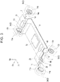
FIG. 2 is a vertical sectional view schematically illustrating the inside of the electric vehicle ofFIG. 1 ; -
FIG. 3 is a perspective view schematically illustrating a braking device; -
FIG. 4 is a view illustrating a schematic configuration of the braking device; -
FIG. 5 is a view schematically illustrating brake fluid pressure generation devices inFIG. 4 (a brake actuator, a brake unit, and a brake pedal unit); -
FIG. 6 is a plan view schematically illustrating a state where the brake fluid pressure generation devices inFIG. 5 are mounted on the vehicle; -
FIG. 7 is a view of the brake fluid pressure generation devices inFIG. 6 when the brake fluid pressure generation devices are viewed from a predetermined position behind them; and -
FIG. 8 is a view of the brake fluid pressure generation devices inFIG. 6 when the brake fluid pressure generation devices are viewed from their left side faces. - The following describes the best mode for carrying out the invention in detail with reference to the attached drawings.
- One embodiment of the present invention is illustrated in
FIGS. 1 to 8 . As illustrated inFIG. 1 , anelectric vehicle 1 described in the present embodiment has an external appearance that is greatly different from a manual driving vehicle including a conventional and general driver seat in that theelectric vehicle 1 has a vehicle body that is almost symmetrical in an advancing direction (see an arrow inFIG. 1 ),wheels electric vehicle 1, respectively, there is no hood or the like covering an engine compartment (a motor room), and an almost entire surface of avehicle side face 1c is configured as a doorway. - Note that, since the
electric vehicle 1 can advance to both sides in the advancing direction in generally the same mode, there is no concept of a front side and a rear side in theelectric vehicle 1. However, for convenience, the left side inFIG. 1 is described as afront end portion 1a in the vehicle front-rear direction, and the right side inFIG. 1 is described as arear end portion 1b in the vehicle front-rear direction. Further, in each of the drawings, an arrow Fr indicates the front side in the vehicle front-rear direction, an arrow Rh indicates the right side in the vehicle width direction, and an arrow Up indicates the upper side. Further, the manual driving vehicle indicates a vehicle including a driver seat that allows a user to operate a steering wheel, an accelerator pedal, and a brake pedal in a state where the user sits on the driver seat. - Note that the
electric vehicle 1 is a vehicle in which so-called "automated driving" is enabled, and because of this, not only the external appearance but also the inside of theelectric vehicle 1 is greatly different from that of the manual driving vehicle including a conventional and general driver seat, as illustrated inFIG. 2 . Note that the "automated driving" is a concept that includes not only fully-automated driving that does not need any operation by an occupant at all, but also semi-automated driving in which the occupant performs auxiliary operations. - For example, the
electric vehicle 1 performs automated driving such that an ECU 50 (seeFIG. 4 ) as a control device actuates an electric drive motor 51 (seeFIG. 3 ), a steering actuator (not shown), a brake actuator 20 (seeFIG. 3 ), and so on based on information from a camera, a sensor, a radar, a GPS antenna, and so on (not shown), commands transmitted from an external server through a network, and so on. - Therefore, in the
electric vehicle 1, the presence of a so-called "driver" is not essential. As illustrated inFIG. 2 , a driver seat configured such that a user operates a steering wheel, an accelerator pedal, and a brake pedal in a state where the user sits on the driver seat is not provided in avehicle cabin 4. For example, in thevehicle cabin 4,occupant seats vehicle cabin 4 in the vehicle front-rear direction such that theoccupant seats wheels 2 or thewheels 3, are not permanently provided in thevehicle cabin 4. Because of this, a proportion of thevehicle cabin 4 in the entireelectric vehicle 1 is very large. Note that the state where "the operation part is not permanently provided in thevehicle cabin 4" includes not only a case where the operation part is not provided at all in theelectric vehicle 1 itself, but also a case where the operation part that is normally hidden in afirst storage chamber 5, asecond storage chamber 7, or a third storage chamber 6 appears in thevehicle cabin 4 as a result of a button operation and so on, for example, when an unexpected situation occurs. - As a matter of course, the
electric vehicle 1 is configured to perform the fully-automated driving by theECU 50 and so on and also perform the semi-automated driving in which an auxiliary operation is performed by an operator as a monitoring person who is in thevehicle cabin 4. - For example, a system of the
electric vehicle 1 is configured such that the operator monitors situations around theelectric vehicle 1 when a surrounding image captured by a camera is projected on a tablet PC (not shown) owned by the operator, and the operator actuates an emergency stop brake or the like by pressing a button icon on an image on the tablet PC. - Note that the presence of the operator in the
vehicle cabin 4 is also not essential, and for example, an operator and so on in an external management center may play a role of the operator inside thevehicle cabin 4, or an external server may play a similar role. - Further, in the
electric vehicle 1, thefirst storage chamber 5 and thesecond storage chamber 7 are provided in thefront end portion 1a and therear end portion 1b of theelectric vehicle 1, respectively, such that thefirst storage chamber 5 and thesecond storage chamber 7 partially overlap thevehicle cabin 4 in the vehicle front-rear direction, as illustrated inFIG. 2 . In thefirst storage chamber 5 and thesecond storage chamber 7, driving system apparatuses and electric system apparatuses such as theECU 50, theelectric drive motor 51, the steering actuator, and thebrake actuator 20 are stored. - More specifically, the
first storage chamber 5 placed on the front side in the vehicle front-rear direction and thesecond storage chamber 7 placed on the rear side in the vehicle front-rear direction are separated from thevehicle cabin 4 by frame members such as front side members 65 (seeFIG. 6 ) and a crossmember 63 (seeFIG. 6 ) to be described later, and panel members of a cabin constituting the vehicle cabin 4 (hereinafter also referred to as aframe member 8 or the like). Thus, in theelectric vehicle 1, spaces above thefirst storage chamber 5 and thesecond storage chamber 7 can be used as thevehicle cabin 4. - Note that the
electric vehicle 1 in the present embodiment employs a drive system in which theelectric drive motor 51 inputs driving force into therear wheels 3. Theelectric drive motor 51 uses abattery 52 as a power source. Thebattery 52 is arranged in the third storage chamber 6 provided under a floor of thevehicle cabin 4 of theelectric vehicle 1. - As such, by elaborating configurations, structures, and arrangement of various pieces of onboard equipment, the
electric vehicle 1 of the present embodiment that is greatly different from a manual driving vehicle including a conventional and general driver seat is achieved as a vehicle in which the proportion of thevehicle cabin 4 in the entireelectric vehicle 1 is very large (proportions of thefirst storage chamber 5, thesecond storage chamber 7, and so on where the onboard equipment is stored are very low), as described above. - The following describes details of a functional configuration, a structure, arrangement, and so on of a
braking device 10 as a part of factors that achieve such a relativelywide vehicle cabin 4. - The
braking device 10 is used to brake thewheels FIG. 3 , thebraking device 10 includes thebrake actuator 20 as a primary brake fluid pressure generation device, thebrake unit 30 as a secondary brake fluid pressure generation device, thebrake pedal unit 40 as an emergency brake fluid pressure generation device, a wheel brake unit (its reference numeral is omitted) to be described below, and so on. - Details of configurations of the
brake actuator 20, thebrake unit 30, and thebrake pedal unit 40 will be described later, but thebrake actuator 20 and thebrake unit 30 are electrically actuated devices configured to generate brake fluid pressure inelectric motors 26, 36 (seeFIG. 5 ), respectively. Thebrake pedal unit 40 is a pneumatically actuated device configured to operate by compressed air filled in anair tank 48 arranged in the third storage chamber 6. Theelectric motors battery 52 as a power source, thebattery 52 being arranged in the third storage chamber 6. - Further, the wheel brake unit is configured to brake (decelerate or stop) the
wheels brake actuator 20, thebrake unit 30, and thebrake pedal unit 40. The wheel brake unit includes first tofourth brake pipes fourth brake calipers fourth brake discs - The
first brake caliper 11a and thefirst brake disc 11b are provided in a part supporting a right front wheel (indicated by areference numeral 2a inFIGS. 3 and4 ). Thefirst brake caliper 11a is connected to afirst port 23a (seeFIG. 4 ) of thebrake actuator 20 via thefirst brake pipe 11 extending to the right side in the vehicle width direction inside thefirst storage chamber 5. - The
second brake caliper 12a and thesecond brake disc 12b are provided in a part supporting a left front wheel (indicated by areference numeral 2b inFIGS. 3 and4 ). Thesecond brake caliper 12a is connected to asecond port 23b (seeFIG. 4 ) of thebrake actuator 20 via thesecond brake pipe 12 extending to the left side in the vehicle width direction inside thefirst storage chamber 5. - The
third brake caliper 13a and thethird brake disc 13b are provided in a part supporting a right rear wheel (indicated by areference numeral 3a inFIGS. 3 and4 ). Thethird brake caliper 13a is connected to athird port 24a (seeFIG. 4 ) of thebrake actuator 20 via thethird brake pipe 13. Thethird brake pipe 13 first extends to the left side in the vehicle width direction inside thefirst storage chamber 5 and then extends rearward in the vehicle front-rear direction inside the third storage chamber 6 so as to reach thesecond storage chamber 7. Then, thethird brake pipe 13 extends to the right side in the vehicle width direction inside thesecond storage chamber 7. - The
fourth brake caliper 14a and thefourth brake disc 14b are provided in a part supporting a left rear wheel (indicated by areference numeral 3b inFIGS. 3 and4 ). Thefourth brake caliper 14a is connected to afourth port 24b (seeFIG. 4 ) of thebrake actuator 20 via thefourth brake pipe 14. Thefourth brake pipe 14 is configured such that, after thefourth brake pipe 14 reaches thesecond storage chamber 7 similarly to thethird brake pipe 13, thefourth brake pipe 14 extends to the left side in the vehicle width direction inside thesecond storage chamber 7. - As illustrated in
FIG. 4 , as a brake fluid pressure transmission route in thebraking device 10, thebrake unit 30 and thebrake pedal unit 40 are placed on the most upstream side, and thebrake actuator 20 is placed on the downstream side from thebrake unit 30 and thebrake pedal unit 40, so that brake fluid pressure is supplied from thebrake actuator 20 to the first tofourth brake calipers - The
brake actuator 20 includes abrake ECU 21, anactuator body portion 22, areservoir tank 25, theelectric motor 26, and so on. - The
brake ECU 21 is connected to theECU 50 via a communication line and is configured to actuate theelectric motor 26 based on a braking force request calculated by theECU 50 based on information (a vehicle speed, a distance to a stop line and an obstacle, and so on) from the sensor, the camera, and so on so that theelectric motor 26 pumps up hydraulic fluid from thereservoir tank 25 and pressurizes the hydraulic fluid.
That is, thebrake actuator 20 is configured to generate brake fluid pressure as much as necessary (to an extent requested by the ECU 50) when necessary (when theECU 50 makes a request). - The
actuator body portion 22 is divided into afirst fluid chamber 23 and asecond fluid chamber 24, as illustrated inFIG. 4 . - The first and
second ports first fluid chamber 23, and the hydraulic fluid pressurized by theelectric motor 26 based on a command from thebrake ECU 21 is supplied from the first andsecond ports second brake calipers - The third and
fourth ports second fluid chamber 24, and the hydraulic fluid pressurized by theelectric motor 26 based on the command from thebrake ECU 21 is supplied from the third andfourth ports fourth brake calipers - Since the
actuator body portion 22 is divided into two fluid chambers, i.e., thefirst fluid chamber 23 and thesecond fluid chamber 24, as such, even if one of the fluid chambers is broken or the like, it is possible to supply the brake fluid pressure to thewheels - Further, since the
brake actuator 20 is placed on the downstream side from thebrake unit 30, even when thebrake unit 30 has a malfunction, thebrake actuator 20 can independently supply the brake fluid pressure to the first tofourth brake calipers - The
brake unit 30 is configured such that, even in a case where thebrake actuator 20 operates normally, when relatively large braking force is required, thebrake unit 30 generates brake fluid pressure so as to assist thebrake actuator 20. In the meantime, thebrake unit 30 is configured to generate brake fluid pressure instead of thebrake actuator 20 when thebrake actuator 20 has a malfunction. - The
brake unit 30 includes abrake ECU 31, amaster cylinder 32, areservoir tank 35, theelectric motor 36, anaccumulator 37, a firstelectromagnetic valve 38, a secondelectromagnetic valve 39, and so on. - As illustrated in
FIG. 5 , themaster cylinder 32 is configured to generate brake fluid pressure in accordance with strokes of first andsecond pistons cylinder housing 33. - First to fifth fluid chambers R1, R2, R3, R4, R5 are defined by the
cylinder housing 33 of themaster cylinder 32, the first andsecond pistons input piston 41. - The first fluid chamber R1 is connected to the
reservoir tank 35 and thefirst fluid chamber 23 of thebrake actuator 20, and hydraulic fluid inside the first fluid chamber R1 is pressurized by thefirst piston 34a. - The second fluid chamber R2 is provided between the
first piston 34a and thesecond piston 34b and is connected to thereservoir tank 35 and thesecond fluid chamber 24 of thebrake actuator 20. Hydraulic fluid inside the second fluid chamber R2 is pressurized by thesecond piston 34b. - A
rib portion 34c is provided in thesecond piston 34b such that the fourth fluid chamber R4 is provided on a first side of therib portion 34c (a side close to the first and second fluid chambers R1, R2), and the fifth fluid chamber R5 is provided on a second side of therib portion 34c (a side close to the third fluid chamber R3). - The third fluid chamber R3 is connected to the
reservoir tank 35 and the fourth fluid chamber R4, and hydraulic fluid inside the third fluid chamber R3 is pressurized by theinput piston 41. Note that the third fluid chamber R3 and the fourth fluid chamber R4 are connected to each other via the firstelectromagnetic valve 38 that opens in an energized state. - The
electric motor 36 is configured to pressurize hydraulic fluid pumped up from thereservoir tank 35 and accumulate the hydraulic fluid thus pressurized in theaccumulator 37. Theaccumulator 37 is connected to the fifth fluid chamber R5 via the secondelectromagnetic valve 39 that opens in the energized state. - The
brake ECU 31 is connected to theECU 50 via a communication line, and based on a braking force request calculated by theECU 50, thebrake ECU 31 opens the secondelectromagnetic valve 39 so as to release the high-pressure hydraulic fluid so that the first andsecond pistons cylinder housing 33 by the high-pressure hydraulic fluid. - Note that the
brake ECU 31 is configured to maintain the firstelectromagnetic valve 38 in the energized state (a valve open state) except when thebrake ECU 31 actuates thebrake pedal unit 40 and also maintain the secondelectromagnetic valve 39 in a non-energized state (a valve close state) except when thebrake ECU 31 actuates thebrake unit 30. - The brake fluid pressure thus generated in accordance with the strokes of the first and
second pistons second ports master cylinder 32 to the first tofourth brake calipers fluid chambers brake actuator 20, as illustrated inFIG. 4 . - As such, the
brake unit 30 generates the brake fluid pressure independently from thebrake actuator 20. Accordingly, even in a case where an electric system of thebrake actuator 20 has a malfunction, when at least either one of the first and secondfluid chambers wheels - The
brake pedal unit 40 functions as an emergency brake fluid pressure generation device mainly at the time when thebrake actuator 20 and thebrake unit 30 are inoperative. - For example, the
brake pedal unit 40 is configured to generate brake fluid pressure instead of thebrake actuator 20 and thebrake unit 30 when theelectric vehicle 1 has power outage or the like. - As illustrated in
FIGS. 4 and5 , thebrake pedal unit 40 includes theinput piston 41, arod 42, abrake pedal 43, anair cylinder 44, asolenoid BOX 45, ahose 46, ahose 47, theair tank 48, and so on. - The
input piston 41 is inserted into thecylinder housing 33 of thebrake unit 30 in a slidable manner. Therod 42 connects theinput piston 41 to thebrake pedal 43. - The
brake pedal 43 is biased by a spring (not shown) to an opposite direction from a direction where theinput piston 41 is pushed toward a pressurizing side, and when a valve inside thesolenoid BOX 45 closes, thebrake pedal 43 returns to its original position. - The
air cylinder 44 is connected to theair tank 48 via thesolenoid BOX 45 configured such that the valve inside thesolenoid BOX 45 closes in the energized state. Theair cylinder 44 is configured to rotate thebrake pedal 43 when theair cylinder 44 is actuated by the compressed air filled in theair tank 48 as the valve (not shown) inside thesolenoid BOX 45 opens at the time when a given condition such as power outage of theelectric vehicle 1 is satisfied. Note that thesolenoid BOX 45 is energized so as to be maintained in a state where the valve (not shown) inside thesolenoid BOX 45 is closed except when theECU 50 actuates thebrake pedal unit 40. - The
air cylinder 44 communicates with thesolenoid BOX 45 via thehose 46, and thesolenoid BOX 45 communicates with theair tank 48 via thehose 47. - Note that the
input piston 41, therod 42, and thebrake pedal 43 constitute a pushing member configured to push the first andsecond pistons air cylinder 44, thesolenoid BOX 45, and thehoses brake pedal 43. - In such a
brake pedal unit 40, thebrake pedal 43 is rotated by theair cylinder 44 so as to push the input piston 41 (seeFIG. 5 ) toward the pressurizing side. Hereby, the first andsecond pistons master cylinder 32 are caused to stroke and generate brake fluid pressure. - The brake fluid pressure thus generated by the
master cylinder 32 is supplied from the first andsecond ports fourth brake calipers fluid chambers brake actuator 20. - Thus, the
brake pedal unit 40 also generates the brake fluid pressure by use of themaster cylinder 32. That is, in the present embodiment, both thebrake unit 30 and thebrake pedal unit 40 use thesingle master cylinder 32. - As such, the
brake pedal unit 40 generates the brake fluid pressure independently from thebrake actuator 20 and thebrake unit 30. Accordingly, even in a case where the electric systems of thebrake actuator 20 and thebrake unit 30 have malfunctions, for example, when the given condition is satisfied, thebrake pedal unit 40 can supply the brake fluid pressure to thewheels - As described above, in the present embodiment, (A) at normal time when the electric system does not have any malfunction or the like, the
brake actuator 20 supplies the brake fluid pressure as the primary brake fluid pressure generation device. - In the meantime, (B) at abnormal time when the electric system and so on have a malfunction, (B - 1) in a case where the
brake actuator 20 has a malfunction, thebrake unit 30 supplies the brake fluid pressure, and (B - 2) in a case where thebrake actuator 20 and thebrake unit 30 have malfunctions due to power outage or the like, thebrake pedal unit 40 supplies the brake fluid pressure. - Note that the brake fluid pressure of the emergency stop brake operated by the operator may be generated by any of the
brake actuator 20, thebrake unit 30, and thebrake pedal unit 40. - Although not illustrated herein, the first to
fourth brake calipers fourth ports fourth brake discs electric vehicle 1 is decelerated or stopped. - Next will be briefly described an example of a device configuration in which only the
brake actuator 20 is actuated in the case of (A), thebrake unit 30 is actuated in the case of (B - 1), and thebrake pedal unit 40 is actuated in the case of (B - 2). - Here, in the case of (A), the
brake ECU 31 closes the second electromagnetic valve 39 (the non-energized state), and thebrake ECU 21 of thebrake actuator 20 actuates theelectric motor 26 so that theelectric motor 26 pumps up the hydraulic fluid from thereservoir tank 25 and pressurizes the hydraulic fluid. Hereby, theelectric vehicle 1 is decelerated or stopped by the brake fluid pressure from thebrake actuator 20 only. - In the meantime, in the case of (B - 1), the
brake ECU 31 brings the secondelectromagnetic valve 39 into the energized state so that the secondelectromagnetic valve 39 opens, and thebrake ECU 31 supplies hydraulic fluid stored in theaccumulator 37 in a pressurized state to the fifth fluid chamber R5. Here, since the firstelectromagnetic valve 38 is in the energized state (in the valve open state), fluid pressure in the third fluid chamber R3 and fluid pressure in the fourth fluid chamber R4 that faces the third fluid chamber R3 cancel each other, so that thesecond piston 34b operates only with fluid pressure in the fifth fluid chamber R5. Thus, in the case of (B - 1), theelectric vehicle 1 is decelerated or stopped by the brake fluid pressure from thebrake unit 30 only. - Further, in the case of (B - 2), the first
electromagnetic valve 38 closes and the valve inside thesolenoid BOX 45 opens due to power outage, for example. - As a result, the
air cylinder 44 is actuated by the compressed air filled in theair tank 48 so as to rotate thebrake pedal 43, thereby resulting in that theinput piston 41 is pushed toward the pressurizing side, and the fluid pressure in the third fluid chamber R3 increases. - Here, when the first
electromagnetic valve 38 is closed, the fluid pressure in the third fluid chamber R3 does not cancel the fluid pressure in the fourth fluid chamber R4 that faces the third fluid chamber R3, so that thesecond piston 34b operates only with the fluid pressure in the third fluid chamber R3. Hereby, theelectric vehicle 1 is decelerated or stopped by the brake fluid pressure from thebrake pedal unit 40 only. - As described above, at normal time, the
electric vehicle 1 of the present embodiment can be decelerated or stopped by the power of thebattery 52, and when theelectric vehicle 1 has power outage or the like, theelectric vehicle 1 can be decelerated or stopped by the compressed air in theair tank 48 without a need of stepping force or the like applied by the driver. Accordingly, it is possible to employ the layout in which the brake pedal is not permanently provided in thevehicle cabin 4 as described above. - As illustrated in
FIG. 3 , thebrake actuator 20, thebrake unit 30, thebrake pedal unit 40, and anair conditioner unit 53 as an air-conditioning device are stored in thefirst storage chamber 5, and theelectric drive motor 51 as a driving source of theelectric vehicle 1 is stored inside thesecond storage chamber 7 provided on the opposite side from thefirst storage chamber 5. - As such, in the
electric vehicle 1 in which thevehicle cabin 4 partially overlaps thefirst storage chamber 5 and thesecond storage chamber 7 in the vehicle front-rear direction, theelectric drive motor 51, the brake fluid pressure generation devices (20, 30, 40), and theair conditioner unit 53 are arranged in thefirst storage chamber 5 and thesecond storage chamber 7 in a divided manner. Hereby, while respective spaces of thefirst storage chamber 5 and thesecond storage chamber 7 are used effectively, load distribution to the front side and the rear side of theelectric vehicle 1 can be set appropriately. - As illustrated in
FIG. 8 , thebrake actuator 20, thebrake unit 30, and thebrake pedal unit 40 are stored at a position facing anopening 8b provided in apartition wall 8a that separates thevehicle cabin 4 from thefirst storage chamber 5. A cover 9 configured to open and close theopening 8b is provided in theopening 8b. - Note that the
partition wall 8a is provided in theframe member 8. Although not illustrated herein, for example, the cover 9 can be constituted by a part of trim components (e.g., a shelf, a trim panel, theoccupant seat 4a, and so on) of thevehicle cabin 4. - Hereby, when the
opening 8b is closed by the cover 9, thebrake actuator 20, thebrake unit 30, and thebrake pedal unit 40 are not exposed to thevehicle cabin 4 side. In the meantime, when the cover 9 is removed to open theopening 8b, thebrake actuator 20, thebrake unit 30, and thebrake pedal unit 40 are exposed to thevehicle cabin 4 side. - Consequently, at the time of performing maintenance on the
brake actuator 20, thebrake unit 30, and thebrake pedal unit 40, the maintenance is performable from thevehicle cabin 4 side through theopening 8b. Thus, the workability of the maintenance is improved in comparison with a case where thebrake actuator 20, thebrake unit 30, and thebrake pedal unit 40 are stored at a position where they are not observable from theopening 8b or a position far from theopening 8b, for example. - Next will be described the arrangement of the
brake actuator 20, thebrake unit 30, and thebrake pedal unit 40 in thefirst storage chamber 5. - First briefly described is the
first storage chamber 5. As illustrated inFIG. 6 , a pair of right and left side rails 61 is provided in a location corresponding to the third storage chamber 6 inFIG. 2 such that the right and left side rails 61 are placed on both end sides of the third storage chamber 6 in the vehicle width direction and extend in the vehicle front-rear direction. - The side rails 61 are connected to each other via a
crossmember 62 extending in the vehicle width direction. Front end portions of the side rails 61 are connected to alower crossmember 64 out of twocrossmembers FIG. 8 . Thefirst storage chamber 5 is provided in front of thecrossmembers - More specifically, as illustrated in
FIG. 6 , a pair of right and leftfront side members 65 is provided such that the right and leftfront side members 65 extend forward in the vehicle front-rear direction from both end portions, in the vehicle width direction, of theupper crossmember 63, and front end portions of the right and leftfront side members 65 are connected to each other via acrossmember 66. - Further, a pair of front and
rear crossmembers 67, 68 (seeFIG. 8 ) is provided so as to stretch over between the right and leftfront side members 65 such that the front andrear crossmembers front side members 65 and thecrossmembers - As illustrated in
FIG. 7 , each of thecrossmembers front side member 65. Note that areference numeral 69 inFIGS. 6 and7 indicates a suspension tower. - With such a configuration, the right and left sides of the
first storage chamber 5 are defined by the right and leftfront side members 65, the front and rear sides of thefirst storage chamber 5 are defined by thecrossmembers first storage chamber 5 is defined by thecrossmembers - As illustrated in
FIGS. 4 ,6 , and7 , in thebrake unit 30, thereservoir tank 35 extending in the same direction as thecylinder housing 33 is provided above thecylinder housing 33 extending in a longitudinal direction of themaster cylinder 32, that is, in a sliding direction of the first andsecond pistons - Therefore, as the
brake unit 30 as a whole, a length of thebrake unit 30 in an extending direction (a longitudinal direction) of thecylinder housing 33 is longer than a length of thebrake unit 30 in a direction (a direction perpendicular to the longitudinal direction) orthogonal to the extending direction of thecylinder housing 33 and a length of thebrake unit 30 in the up-down direction. Note that thebrake ECU 31 is provided on a side face of thecylinder housing 33. - As such, as illustrated in
FIGS. 6 and7 , thebrake unit 30 with the longitudinal direction being along the extending direction of the cylinder housing 33 (the sliding direction of the first andsecond pistons first storage chamber 5 such that the longitudinal direction of thebrake unit 30 is parallel to the vehicle width direction. - More specifically, as illustrated in
FIG. 8 , asupport bracket 67a extending in the vehicle front-rear direction is provided so as to stretch over between the twocrossmembers - As illustrated in
FIG. 6 , as aflange portion 32c of thecylinder housing 33 is fastened bybolts 103 to an upper end portion of afirst bracket 70 extending upward from thesupport bracket 67a, thebrake unit 30 is arranged such that its longitudinal direction is along the vehicle width direction. - Further, as illustrated in
FIG. 6 , thebrake pedal unit 40 that shares themaster cylinder 32 with thebrake unit 30 is arranged in thefirst storage chamber 5 so as to be arrayed with thebrake unit 30 in the vehicle width direction. - More specifically, the
rod 42 extends in the vehicle width direction, therod 42 being connected to theinput piston 41 inserted in thecylinder housing 33 extending in the vehicle width direction. Therefore, thebrake pedal 43 rotatably attached to a distal end portion of therod 42 is also arrayed with thebrake unit 30 in the vehicle width direction. - Further, the
air cylinder 44 configured to rotate thebrake pedal 43 is fixed to abracket 65a extending in the vehicle width direction from thefront side member 65 such that theair cylinder 44 is arrayed with thebrake unit 30 and thebrake pedal 43 in the vehicle width direction. - Note that the
air tank 48 configured to supply the compressed air to theair cylinder 44 is arranged above thecrossmember 62 provided below thevehicle cabin 4 and behind thefirst storage chamber 5. - Hereby, in the present embodiment, as illustrated in
FIG. 6 , thebrake unit 30 and thebrake pedal unit 40 extending in the vehicle width direction are arrayed generally linearly in the vehicle width direction. - In the
brake actuator 20, as illustrated inFIGS. 6 and7 , thebrake ECU 21, the actuator body portion 22 (including the reservoir tank 25), and amotor housing 27 in which theelectric motor 26 is housed are provided so as to be arrayed in this order. Therefore, as thebrake actuator 20 as a whole, a length of thebrake actuator 20 in an array direction (also referred to as an arrangement direction) where those members are arrayed is longer than a length of thebrake actuator 20 in a direction orthogonal to the arrangement direction and a length of thebrake actuator 20 in the up-down direction. - As such, as illustrated in
FIGS. 6 and7 , thebrake actuator 20 provided so as to be long in the arrangement direction is arranged behind thebrake pedal 43 in the vehicle front-rear direction (near thebrake unit 30 and behind thebrake unit 30 in the vehicle front-rear direction) in thefirst storage chamber 5 such that the longitudinal direction (the arrangement direction) of thebrake actuator 20 is parallel to the vehicle width direction. - More specifically, as illustrated in
FIGS. 6 and8 , an L-shapedsecond bracket 80 is attached to theupper crossmember 63. Thesecond bracket 80 is configured such that, after thesecond bracket 80 extends forward in the vehicle front-rear direction from a front end of thecrossmember 63, thesecond bracket 80 is bent at a right angle and extends to the right side in the vehicle width direction. - A distal end portion of the
second bracket 80 and the upper end portion of thefirst bracket 70 are connected to anactuator bracket 90 viarespective bolts second brackets actuator bracket 90. - The
brake actuator 20 is fastened to theactuator bracket 90 by bolts as illustrated inFIG. 7 , and thus, thebrake actuator 20 is arranged behind thebrake pedal 43 in the vehicle front-rear direction such that thebrake actuator 20 is parallel to the vehicle width direction as illustrated inFIG. 6 . - Here, as illustrated in
FIGS. 7 and8 , thebrake actuator 20, thebrake unit 30, and thebrake pedal unit 40 are arranged at generally the same height in thefirst storage chamber 5. Further, generally, it is assumed that thebrake pedal 43 is rotated by stepping force applied by a driver, and therefore, thebrake pedal 43 is rotated below therod 42. However, in the present embodiment, thebrake pedal 43 is rotated by theair cylinder 44, so that thebrake pedal 43 is rotated above therod 42 as illustrated inFIGS. 7 and8 . - Hereby, as illustrated in
FIG. 8 , a relatively large space is formed below thebrake actuator 20 and thebrake pedal unit 40 in thefirst storage chamber 5. On this account, in the present embodiment, the air conditioner unit (the air-conditioning device) 53 is arranged in the space as illustrated inFIGS. 7 and8 . - As described above, in the embodiment to which the present invention is applied, the
vehicle cabin 4 partially overlaps thefirst storage chamber 5 and thesecond storage chamber 7 in the vehicle front-rear direction, and then, theelectric drive motor 51, the brake fluid pressure generation devices (20, 30, 40), and theair conditioner unit 53 are stored in thefirst storage chamber 5 and thesecond storage chamber 7 in a divided manner. Accordingly, while respective spaces of thefirst storage chamber 5 and thesecond storage chamber 7 are used effectively, load distribution to the front side and the rear side of the vehicle can be set appropriately. - Besides, in the above embodiment, the
battery 52 is arranged in the third storage chamber 6 under the floor of thevehicle cabin 4, that is, in the middle of theelectric vehicle 1 in the vehicle front-rear direction. This is advantageous to appropriately set load distribution to the front side and the rear side of theelectric vehicle 1. - Further, the brake fluid pressure generation devices (20, 30, 40) as constituents that require regular maintenance are stored in the
first storage chamber 5 separated from thevehicle cabin 4 such that the brake fluid pressure generation devices face theopening 8b. - Consequently, at the time of performing maintenance on the
brake actuator 20 and thebrake unit 30, the maintenance is performable while thebrake actuator 20 and thebrake unit 30 are observed from thevehicle cabin 4 side through theopening 8b. Thus, the workability of the maintenance is improved in comparison with a case where thebrake actuator 20 and thebrake unit 30 are stored at a position where thebrake actuator 20 and thebrake unit 30 are not observable from theopening 8b or at a position far from theopening 8b, for example. In addition, the degree of freedom of the layout in thevehicle cabin 4 is improved. - Further, in the present embodiment, the brake fluid pressure generation devices (20, 30, 40) and the air-conditioning device (the air conditioner unit 53) are arranged so as to overlap each other in the vehicle front-rear direction. Accordingly, in comparison with a case where the brake fluid pressure generation devices (20, 30, 40) and the air-conditioning device (the air conditioner unit 53) are arranged so as not to overlap each other, the
first storage chamber 5 in which the brake fluid pressure generation devices (20, 30, 40) and the air-conditioning device (the air conditioner unit 53) are stored can be reduced in size in the vehicle front-rear direction. This is accordingly advantageous to increase the space for thevehicle cabin 4 as large as possible. - Further, in the present embodiment, the
brake unit 30 is arranged such that the longitudinal direction of themaster cylinder 32, that is, the sliding direction of the first andsecond pistons - This allows an axle (not shown), the
crossmembers brake unit 30 inside thefirst storage chamber 5. - On this account, in comparison with a case where the
brake unit 30 is arranged, for example, in parallel to the vehicle front-rear direction like a manual driving vehicle including a conventional and general driver seat, in other words, a case where many devices and members extending in the vehicle width direction are provided together with thebrake unit 30 arranged in parallel to the vehicle front-rear direction, thefirst storage chamber 5 can be reduced in size in the vehicle front-rear direction. This is accordingly advantageous to increase the space for thevehicle cabin 4 as large as possible. - Further, as illustrated in
FIG. 2 , thefirst storage chamber 5 is provided to extend rearward in the vehicle front-rear direction from a part above axles (not shown) of thefront wheels 2. In addition, as illustrated inFIG. 3 , heavy goods including thebrake actuator 20, thebrake unit 30, thebrake pedal unit 40, and theair conditioner unit 53 are stored in thefirst storage chamber 5. Hereby, the heavy goods are arranged above the axels (not shown) of thefront wheels 2 or in a region including a part above the axles of thefront wheels 2 and a part further behind the axles in the vehicle front-rear direction. This makes it possible to increase behavioral stability of theelectric vehicle 1. - Further, when the
brake actuator 20 and thebrake unit 30 are inoperable, the brake fluid pressure can be generated by thebrake pedal unit 40 as an emergency brake fluid pressure generation device by causing the first andsecond pistons master cylinder 32 to stroke. Therefore, it is possible to achieve fail safe. In addition, since thebrake pedal unit 40 is arranged to be arrayed with thebrake unit 30 in the vehicle width direction, it is possible to reduce the size of thefirst storage chamber 5. - Besides, the
brake pedal unit 40 as the emergency brake fluid pressure generation device is stored in thefirst storage chamber 5 such that thebrake pedal unit 40 faces theopening 8b. This makes it possible to improve the workability of maintenance on thebrake pedal unit 40. - Besides, the
brake pedal unit 40 is pneumatically actuated. Accordingly, even when theelectric vehicle 1 has power outage, theelectric vehicle 1 can be surely decelerated or stopped without requesting operations by a driver. Thus, it is not necessary to provide a brake pedal and its equivalent in thevehicle cabin 4, thereby making it possible to further increase the space for thevehicle cabin 4. - Further, the
brake actuator 20 is arranged behind (inwardly from) thebrake unit 30 in the vehicle front-rear direction. Accordingly, even when thebrake unit 30 thus arranged in front of (outwardly from) thebrake actuator 20 in the vehicle front-rear direction is damaged at the time of a vehicle collision, it is possible to lower the possibility of breakage of thebrake actuator 20. - Even when the
brake unit 30 is damaged, it is possible to avoid malfunctions of thewhole braking device 10 because thebrake actuator 20 is provided on the downstream side from thebrake unit 30 in the fluid pressure transmission route and generates the brake fluid pressure independently from thebrake unit 30. - Further, since the
brake actuator 20 is arranged near thebrake unit 30 in thefirst storage chamber 5, it is possible to shorten the first tofourth brake pipes first storage chamber 5 to be compact. - Further, the
brake actuator 20, thebrake unit 30, and thebrake pedal unit 40 are arranged at generally the same height in thefirst storage chamber 5, and the air conditioner unit (air-conditioning device) 53 is arranged in the space formed below thebraking device 10. In other words, the brake fluid pressure generation devices (20, 30, 40) are arranged so as to be vertically arrayed with theair conditioner unit 53 in the vehicle up-down direction. Accordingly, it is possible to further reduce the size of thefirst storage chamber 5. - Due to the synergistic effect obtained by the compactification of the
first storage chamber 5 and the forming of thefirst storage chamber 5 and thesecond storage chamber 7 such that thefirst storage chamber 5 and thesecond storage chamber 7 partially overlap thevehicle cabin 4 in the vehicle front-rear direction, it is possible to more surely increase the space for thevehicle cabin 4. - In addition, the
brake pedal unit 40 employs a configuration in which the brake fluid pressure is generated such that thebrake pedal 43 causes the first andsecond pistons master cylinder 32 to stroke, except that pneumatic pressure is used instead of stepping force applied by a driver. On this account, a master cylinder, a brake pedal, and so on to be used in a conventional and general manual driving vehicle can be used just as they are, for example. This is advantageous to restrain an increase in cost. - The present invention is not limited to the above embodiment and can be modified appropriately within the scope of claims and within a scope equivalent thereto.
- (1) The above embodiment deals with an example in which the brake fluid pressure generation devices (the
brake actuator 20, thebrake unit 30, and the brake pedal unit 40) are provided in thebraking device 10. However, the present invention is not limited to this.
For example, one brake fluid pressure generation device may be used, provided that the brake fluid pressure generation device generates brake fluid pressure in accordance with strokes of pistons sliding in a cylinder housing, and the brake fluid pressure generation device is arranged in a storage chamber such that a sliding direction of the pistons is parallel to the vehicle width direction. - (2) The above embodiment deals with an example in which the
brake pedal unit 40 as the emergency brake fluid pressure generation device is pneumatically actuated. However, the present invention is not limited to this.
For example, thebrake pedal unit 40 may be hydraulically actuated or electrically actuated, provided that the brake fluid pressure can be generated by causing the first andsecond pistons brake unit 30 is inoperable, for example. - (3) The above embodiment deals with an example in which the
brake unit 30 and thebrake pedal unit 40 are arrayed in the vehicle width direction, and thebrake actuator 20 is arranged behind thebrake unit 30 and thebrake pedal unit 40 in the vehicle front-rear direction. However, the present invention is not limited to this. For example, thebrake actuator 20, thebrake unit 30, and thebrake pedal unit 40 may be arrayed in the vehicle width direction. - (4) The above embodiment deals with (B - 2) as a case where the
brake pedal unit 40 is actuated. However, the present invention is not limited to this. For example, when theelectric vehicle 1 is parked, thebrake pedal unit 40 may be actuated as a parking brake. - (5) The above embodiment deals with an example in which the
brake actuator 20, thebrake unit 30, and thebrake pedal unit 40 are stored in thefirst storage chamber 5. However, the present invention is not limited to this.
For example, although not illustrated herein, any two brake fluid pressure generation devices (20, 30), (20, 40), or (30, 40) out of thebrake actuator 20, thebrake unit 30, and thebrake pedal unit 40 can be stored in thefirst storage chamber 5. - (6) The above embodiment deals with an example in which both the
brake unit 30 and thebrake pedal unit 40 use themaster cylinder 32 in common. However, the present invention is not limited to this.
For example, although not illustrated herein, thebrake unit 30 and thebrake pedal unit 40 may be configured to includerespective master cylinders 32. - (7) The above embodiment deals with an example in which the
brake actuator 20, thebrake unit 30, thebrake pedal unit 40, and the air conditioner unit 53 (the air-conditioning device) are stored in thefirst storage chamber 5, and theelectric drive motor 51 is stored in thesecond storage chamber 7. However, the present invention is not limited to this.
For example, although not illustrated herein, in a reverse manner to the above, theelectric drive motor 51 can be stored in thefirst storage chamber 5, and thebrake actuator 20, thebrake unit 30, thebrake pedal unit 40, and the air conditioner unit 53 (the air-conditioning device) can be stored in thesecond storage chamber 7. - (8) The above embodiment deals with an example in which the
electric vehicle 1 employs a drive system in which theelectric drive motor 51 inputs driving force into therear wheels 3. However, the present invention is not limited to this.
For example, although not illustrated herein, in a case where such a configuration is employed that theelectric drive motor 51 is stored in thefirst storage chamber 5, and thebrake actuator 20, thebrake unit 30, thebrake pedal unit 40, and the air conditioner unit 53 (the air-conditioning device) are stored in thesecond storage chamber 7, thevehicle 1 may employ a drive system in which theelectric drive motor 51 inputs driving force into thefront wheels 2. - (9) In the above embodiment, it is not necessary to completely separate the
first storage chamber 5 from the third storage chamber 6 and to completely separate thesecond storage chamber 7 from the third storage chamber 6. Thefirst storage chamber 5 may communicate with the third storage chamber 6, and thesecond storage chamber 7 may communicate with the third storage chamber 6. - (10) In the above embodiment, an auxiliary seat for an operator can be provided in the
vehicle cabin 4. - Thus, the above embodiment is just an example in every respect and must not be interpreted restrictively. Further, modifications and alterations belonging to an equivalent range of claims are all included in the present invention.
- The present invention can be used appropriately for an electric vehicle that can transport a passenger by automated driving.
Claims (6)
- An electric vehicle comprising:a motor configured to generate driving force for traveling;a braking device (10) for wheel braking, the braking device (10) including a brake fluid pressure generation device;an air-conditioning device; anda battery as a power source for the motor, wherein:the vehicle is not provided with a driver seat that allows a user to operate a steering wheel, an accelerator pedal, and a brake pedal in a state where the user sits on the driver seat;the vehicle is configured to perform automated driving;a first storage chamber (5) and a second storage chamber (7) are provided in a first end portion and a second end portion of the vehicle in a vehicle front-rear direction, respectively, such that the first storage chamber (5) and the second storage chamber (7) partially overlap a vehicle cabin (4) in the vehicle front-rear direction;a third storage chamber (6) is provided under a floor of the vehicle cabin (4);an occupant seat is provided in either one of first and second end portions inside the vehicle cabin (4) in the vehicle front-rear direction such that the occupant seat faces the other one of the first and second end portions;the motor is stored in either one of the first storage chamber (5) and the second storage chamber (7);the brake fluid pressure generation device and the air-conditioning device are stored in the other one of the first storage chamber (5) and the second storage chamber (7); andthe battery (52) is stored in the third storage chamber (6).
- The electric vehicle according to claim 1, wherein either one of the first and second end portions inside the vehicle cabin (4) in the vehicle front-rear direction is not provided with a steering wheel and a foot brake mechanically connected to wheels.
- The electric vehicle according to claim 1 or 2, wherein the occupant seat is a first occupant seat, and a second occupant seat is provided in the other one of the first and second end portions inside the vehicle cabin (4) in the vehicle front-rear direction such that the second occupant seat faces the one of the first and second end portions.
- The electric vehicle according to any one of claims 1 to 3, wherein the first storage chamber (5) and the second storage chamber (7) extend upward from the third storage chamber (6).
- The electric vehicle according to any one of claims 1 to 4, wherein the brake fluid pressure generation device and the air-conditioning device are arranged so as to overlap each other in the vehicle front-rear direction.
- The electric vehicle according to any one of claims 1 to 5, wherein:the brake fluid pressure generation device includes a reservoir tank in which hydraulic fluid is stored, an actuator body portion configured to supply brake fluid pressure to a wheel brake unit, and an electric motor configured to pressurize the hydraulic fluid in the reservoir tank and supply the hydraulic fluid to the actuator body portion as the brake fluid pressure;elements constituting the brake fluid pressure generation device are arrayed in a vehicle width direction; andthe brake fluid pressure generation device is arranged above the air-conditioning device.
Applications Claiming Priority (1)
| Application Number | Priority Date | Filing Date | Title |
|---|---|---|---|
| JP2019071278A JP7310234B2 (en) | 2019-04-03 | 2019-04-03 | electric vehicle |
Publications (2)
| Publication Number | Publication Date |
|---|---|
| EP3718803A1 true EP3718803A1 (en) | 2020-10-07 |
| EP3718803B1 EP3718803B1 (en) | 2022-12-14 |
Family
ID=69960368
Family Applications (1)
| Application Number | Title | Priority Date | Filing Date |
|---|---|---|---|
| EP20165153.6A Active EP3718803B1 (en) | 2019-04-03 | 2020-03-24 | Electric vehicle |
Country Status (5)
| Country | Link |
|---|---|
| US (1) | US11299193B2 (en) |
| EP (1) | EP3718803B1 (en) |
| JP (1) | JP7310234B2 (en) |
| KR (2) | KR102335844B1 (en) |
| CN (1) | CN111791857B (en) |
Cited By (1)
| Publication number | Priority date | Publication date | Assignee | Title |
|---|---|---|---|---|
| US11299193B2 (en) * | 2019-04-03 | 2022-04-12 | Toyota Jidosha Kabushiki Kaisha | Electric vehicle |
Families Citing this family (1)
| Publication number | Priority date | Publication date | Assignee | Title |
|---|---|---|---|---|
| USD960802S1 (en) * | 2018-06-29 | 2022-08-16 | Zoox, Inc. | Vehicle fascia |
Citations (5)
| Publication number | Priority date | Publication date | Assignee | Title |
|---|---|---|---|---|
| JP2002355143A (en) | 2001-05-31 | 2002-12-10 | Mitsubishi Heavy Ind Ltd | Chair and vehicle |
| US20040262940A1 (en) * | 2003-01-10 | 2004-12-30 | Johnson Robert E. | Small driverless passenger vehicles and systems, and methods for using such vehicles |
| US20170124781A1 (en) * | 2015-11-04 | 2017-05-04 | Zoox, Inc. | Calibration for autonomous vehicle operation |
| US20180265136A1 (en) * | 2017-03-14 | 2018-09-20 | Ford Global Technologies, Llc | Vehicle structure including reinforcement extending between rockers |
| US20180345971A1 (en) * | 2017-05-31 | 2018-12-06 | Zoox, Inc. | Vehicle operation with interchangeable drive modules |
Family Cites Families (25)
| Publication number | Priority date | Publication date | Assignee | Title |
|---|---|---|---|---|
| JPH07245811A (en) * | 1994-03-04 | 1995-09-19 | Honda Motor Co Ltd | Controller for electric car |
| JP2003191757A (en) * | 2001-12-28 | 2003-07-09 | Yamaha Motor Co Ltd | Power-assisted moving car |
| CN1261319C (en) * | 2004-11-11 | 2006-06-28 | 北京电巴科技有限公司 | Electric public transport system |
| CN103209873B (en) * | 2010-11-17 | 2015-08-26 | 本田技研工业株式会社 | The vehicle body mounting configuration of electric brake actuator |
| KR101220768B1 (en) * | 2010-12-28 | 2013-01-21 | 주식회사 포스코 | Uuder Body for Electric Vehicle |
| US9517767B1 (en) | 2015-11-04 | 2016-12-13 | Zoox, Inc. | Internal safety systems for robotic vehicles |
| US9802661B1 (en) * | 2015-11-04 | 2017-10-31 | Zoox, Inc. | Quadrant configuration of robotic vehicles |
| US9701239B2 (en) * | 2015-11-04 | 2017-07-11 | Zoox, Inc. | System of configuring active lighting to indicate directionality of an autonomous vehicle |
| JP6943867B2 (en) | 2015-11-04 | 2021-10-06 | ズークス インコーポレイテッド | Quadrant configuration of robot type vehicle |
| FR3046395B1 (en) * | 2015-12-30 | 2018-05-04 | Faar Ind | AUTONOMOUS VEHICLE WITH COMPARTMENTS |
| CN108173297A (en) * | 2016-12-07 | 2018-06-15 | 中国科学院大连化学物理研究所 | A kind of autonomous/semi-autonomous fuel cell movement electric power system |
| WO2018222375A1 (en) | 2017-05-31 | 2018-12-06 | Zoox, Inc. | Vehicle with interchangeable drive module and drive module |
| CN110719865B (en) | 2017-06-13 | 2023-02-24 | 松下知识产权经营株式会社 | Driving support method, driving support program, and vehicle control device |
| CN107610448A (en) * | 2017-08-21 | 2018-01-19 | 深圳市海梁科技有限公司 | A kind of automatic driving vehicle and its dispatching method and scheduling system |
| JP6477856B1 (en) * | 2017-12-26 | 2019-03-06 | トヨタ自動車株式会社 | Automobile |
| JP6992550B2 (en) * | 2018-01-31 | 2022-01-13 | トヨタ自動車株式会社 | Delivery vehicle and mobile sales system |
| JP7092085B2 (en) * | 2019-04-03 | 2022-06-28 | トヨタ自動車株式会社 | Vehicle braking device |
| JP7078008B2 (en) * | 2019-04-03 | 2022-05-31 | トヨタ自動車株式会社 | Support structure of brake fluid pressure generator |
| JP2020168933A (en) * | 2019-04-03 | 2020-10-15 | トヨタ自動車株式会社 | vehicle |
| JP7143806B2 (en) * | 2019-04-03 | 2022-09-29 | トヨタ自動車株式会社 | vehicle |
| JP7310234B2 (en) * | 2019-04-03 | 2023-07-19 | トヨタ自動車株式会社 | electric vehicle |
| KR102336407B1 (en) * | 2019-04-30 | 2021-12-08 | 현대자동차주식회사 | Vehicle with expandable space |
| JP7275923B2 (en) * | 2019-06-28 | 2023-05-18 | トヨタ自動車株式会社 | In-vehicle braking system |
| JP7200852B2 (en) * | 2019-06-28 | 2023-01-10 | トヨタ自動車株式会社 | electric vehicle |
| US11167798B1 (en) * | 2019-12-27 | 2021-11-09 | Zoox, Inc. | Vehicle energy absorbing structure and techniques |
-
2019
- 2019-04-03 JP JP2019071278A patent/JP7310234B2/en active Active
-
2020
- 2020-03-24 EP EP20165153.6A patent/EP3718803B1/en active Active
- 2020-03-24 KR KR1020200035773A patent/KR102335844B1/en active IP Right Grant
- 2020-03-26 CN CN202010222266.6A patent/CN111791857B/en active Active
- 2020-03-30 US US16/834,580 patent/US11299193B2/en active Active
-
2021
- 2021-10-14 KR KR1020210136659A patent/KR20210127684A/en active Application Filing
Patent Citations (5)
| Publication number | Priority date | Publication date | Assignee | Title |
|---|---|---|---|---|
| JP2002355143A (en) | 2001-05-31 | 2002-12-10 | Mitsubishi Heavy Ind Ltd | Chair and vehicle |
| US20040262940A1 (en) * | 2003-01-10 | 2004-12-30 | Johnson Robert E. | Small driverless passenger vehicles and systems, and methods for using such vehicles |
| US20170124781A1 (en) * | 2015-11-04 | 2017-05-04 | Zoox, Inc. | Calibration for autonomous vehicle operation |
| US20180265136A1 (en) * | 2017-03-14 | 2018-09-20 | Ford Global Technologies, Llc | Vehicle structure including reinforcement extending between rockers |
| US20180345971A1 (en) * | 2017-05-31 | 2018-12-06 | Zoox, Inc. | Vehicle operation with interchangeable drive modules |
Cited By (1)
| Publication number | Priority date | Publication date | Assignee | Title |
|---|---|---|---|---|
| US11299193B2 (en) * | 2019-04-03 | 2022-04-12 | Toyota Jidosha Kabushiki Kaisha | Electric vehicle |
Also Published As
| Publication number | Publication date |
|---|---|
| US11299193B2 (en) | 2022-04-12 |
| JP2020171128A (en) | 2020-10-15 |
| EP3718803B1 (en) | 2022-12-14 |
| JP7310234B2 (en) | 2023-07-19 |
| KR20200117862A (en) | 2020-10-14 |
| US20200317255A1 (en) | 2020-10-08 |
| CN111791857A (en) | 2020-10-20 |
| CN111791857B (en) | 2023-04-07 |
| KR102335844B1 (en) | 2021-12-07 |
| KR20210127684A (en) | 2021-10-22 |
Similar Documents
| Publication | Publication Date | Title |
|---|---|---|
| EP3718803A1 (en) | Electric vehicle | |
| EP3718842B1 (en) | Vehicle braking device | |
| CN111791851B (en) | Brake system | |
| JP7275923B2 (en) | In-vehicle braking system | |
| EP3718843B1 (en) | Vehicle | |
| US11479229B2 (en) | Support structure for brake fluid pressure generation device | |
| JP2020168933A (en) | vehicle | |
| US11104320B2 (en) | Brake bleeding device |
Legal Events
| Date | Code | Title | Description |
|---|---|---|---|
| PUAI | Public reference made under article 153(3) epc to a published international application that has entered the european phase |
Free format text: ORIGINAL CODE: 0009012 |
|
| STAA | Information on the status of an ep patent application or granted ep patent |
Free format text: STATUS: REQUEST FOR EXAMINATION WAS MADE |
|
| 17P | Request for examination filed |
Effective date: 20200324 |
|
| AK | Designated contracting states |
Kind code of ref document: A1 Designated state(s): AL AT BE BG CH CY CZ DE DK EE ES FI FR GB GR HR HU IE IS IT LI LT LU LV MC MK MT NL NO PL PT RO RS SE SI SK SM TR |
|
| AX | Request for extension of the european patent |
Extension state: BA ME |
|
| STAA | Information on the status of an ep patent application or granted ep patent |
Free format text: STATUS: EXAMINATION IS IN PROGRESS |
|
| 17Q | First examination report despatched |
Effective date: 20210917 |
|
| GRAP | Despatch of communication of intention to grant a patent |
Free format text: ORIGINAL CODE: EPIDOSNIGR1 |
|
| STAA | Information on the status of an ep patent application or granted ep patent |
Free format text: STATUS: GRANT OF PATENT IS INTENDED |
|
| INTG | Intention to grant announced |
Effective date: 20220705 |
|
| GRAS | Grant fee paid |
Free format text: ORIGINAL CODE: EPIDOSNIGR3 |
|
| GRAA | (expected) grant |
Free format text: ORIGINAL CODE: 0009210 |
|
| STAA | Information on the status of an ep patent application or granted ep patent |
Free format text: STATUS: THE PATENT HAS BEEN GRANTED |
|
| AK | Designated contracting states |
Kind code of ref document: B1 Designated state(s): AL AT BE BG CH CY CZ DE DK EE ES FI FR GB GR HR HU IE IS IT LI LT LU LV MC MK MT NL NO PL PT RO RS SE SI SK SM TR |
|
| REG | Reference to a national code |
Ref country code: GB Ref legal event code: FG4D |
|
| REG | Reference to a national code |
Ref country code: CH Ref legal event code: EP |
|
| REG | Reference to a national code |
Ref country code: DE Ref legal event code: R096 Ref document number: 602020006853 Country of ref document: DE |
|
| REG | Reference to a national code |
Ref country code: IE Ref legal event code: FG4D |
|
| REG | Reference to a national code |
Ref country code: AT Ref legal event code: REF Ref document number: 1537470 Country of ref document: AT Kind code of ref document: T Effective date: 20230115 |
|
| REG | Reference to a national code |
Ref country code: LT Ref legal event code: MG9D |
|
| REG | Reference to a national code |
Ref country code: NL Ref legal event code: MP Effective date: 20221214 |
|
| PG25 | Lapsed in a contracting state [announced via postgrant information from national office to epo] |
Ref country code: SE Free format text: LAPSE BECAUSE OF FAILURE TO SUBMIT A TRANSLATION OF THE DESCRIPTION OR TO PAY THE FEE WITHIN THE PRESCRIBED TIME-LIMIT Effective date: 20221214 Ref country code: NO Free format text: LAPSE BECAUSE OF FAILURE TO SUBMIT A TRANSLATION OF THE DESCRIPTION OR TO PAY THE FEE WITHIN THE PRESCRIBED TIME-LIMIT Effective date: 20230314 Ref country code: LT Free format text: LAPSE BECAUSE OF FAILURE TO SUBMIT A TRANSLATION OF THE DESCRIPTION OR TO PAY THE FEE WITHIN THE PRESCRIBED TIME-LIMIT Effective date: 20221214 Ref country code: FI Free format text: LAPSE BECAUSE OF FAILURE TO SUBMIT A TRANSLATION OF THE DESCRIPTION OR TO PAY THE FEE WITHIN THE PRESCRIBED TIME-LIMIT Effective date: 20221214 |
|
| PGFP | Annual fee paid to national office [announced via postgrant information from national office to epo] |
Ref country code: FR Payment date: 20230221 Year of fee payment: 4 |
|
| REG | Reference to a national code |
Ref country code: AT Ref legal event code: MK05 Ref document number: 1537470 Country of ref document: AT Kind code of ref document: T Effective date: 20221214 |
|
| PG25 | Lapsed in a contracting state [announced via postgrant information from national office to epo] |
Ref country code: RS Free format text: LAPSE BECAUSE OF FAILURE TO SUBMIT A TRANSLATION OF THE DESCRIPTION OR TO PAY THE FEE WITHIN THE PRESCRIBED TIME-LIMIT Effective date: 20221214 Ref country code: LV Free format text: LAPSE BECAUSE OF FAILURE TO SUBMIT A TRANSLATION OF THE DESCRIPTION OR TO PAY THE FEE WITHIN THE PRESCRIBED TIME-LIMIT Effective date: 20221214 Ref country code: HR Free format text: LAPSE BECAUSE OF FAILURE TO SUBMIT A TRANSLATION OF THE DESCRIPTION OR TO PAY THE FEE WITHIN THE PRESCRIBED TIME-LIMIT Effective date: 20221214 Ref country code: GR Free format text: LAPSE BECAUSE OF FAILURE TO SUBMIT A TRANSLATION OF THE DESCRIPTION OR TO PAY THE FEE WITHIN THE PRESCRIBED TIME-LIMIT Effective date: 20230315 |
|
| PGFP | Annual fee paid to national office [announced via postgrant information from national office to epo] |
Ref country code: DE Payment date: 20230222 Year of fee payment: 4 |
|
| REG | Reference to a national code |
Ref country code: DE Ref legal event code: R084 Ref document number: 602020006853 Country of ref document: DE |
|
| PG25 | Lapsed in a contracting state [announced via postgrant information from national office to epo] |
Ref country code: NL Free format text: LAPSE BECAUSE OF FAILURE TO SUBMIT A TRANSLATION OF THE DESCRIPTION OR TO PAY THE FEE WITHIN THE PRESCRIBED TIME-LIMIT Effective date: 20221214 |
|
| PG25 | Lapsed in a contracting state [announced via postgrant information from national office to epo] |
Ref country code: SM Free format text: LAPSE BECAUSE OF FAILURE TO SUBMIT A TRANSLATION OF THE DESCRIPTION OR TO PAY THE FEE WITHIN THE PRESCRIBED TIME-LIMIT Effective date: 20221214 Ref country code: RO Free format text: LAPSE BECAUSE OF FAILURE TO SUBMIT A TRANSLATION OF THE DESCRIPTION OR TO PAY THE FEE WITHIN THE PRESCRIBED TIME-LIMIT Effective date: 20221214 Ref country code: PT Free format text: LAPSE BECAUSE OF FAILURE TO SUBMIT A TRANSLATION OF THE DESCRIPTION OR TO PAY THE FEE WITHIN THE PRESCRIBED TIME-LIMIT Effective date: 20230414 Ref country code: ES Free format text: LAPSE BECAUSE OF FAILURE TO SUBMIT A TRANSLATION OF THE DESCRIPTION OR TO PAY THE FEE WITHIN THE PRESCRIBED TIME-LIMIT Effective date: 20221214 Ref country code: EE Free format text: LAPSE BECAUSE OF FAILURE TO SUBMIT A TRANSLATION OF THE DESCRIPTION OR TO PAY THE FEE WITHIN THE PRESCRIBED TIME-LIMIT Effective date: 20221214 Ref country code: CZ Free format text: LAPSE BECAUSE OF FAILURE TO SUBMIT A TRANSLATION OF THE DESCRIPTION OR TO PAY THE FEE WITHIN THE PRESCRIBED TIME-LIMIT Effective date: 20221214 Ref country code: AT Free format text: LAPSE BECAUSE OF FAILURE TO SUBMIT A TRANSLATION OF THE DESCRIPTION OR TO PAY THE FEE WITHIN THE PRESCRIBED TIME-LIMIT Effective date: 20221214 |
|
| REG | Reference to a national code |
Ref country code: GB Ref legal event code: 746 Effective date: 20230731 |
|
| PG25 | Lapsed in a contracting state [announced via postgrant information from national office to epo] |
Ref country code: SK Free format text: LAPSE BECAUSE OF FAILURE TO SUBMIT A TRANSLATION OF THE DESCRIPTION OR TO PAY THE FEE WITHIN THE PRESCRIBED TIME-LIMIT Effective date: 20221214 Ref country code: PL Free format text: LAPSE BECAUSE OF FAILURE TO SUBMIT A TRANSLATION OF THE DESCRIPTION OR TO PAY THE FEE WITHIN THE PRESCRIBED TIME-LIMIT Effective date: 20221214 Ref country code: IS Free format text: LAPSE BECAUSE OF FAILURE TO SUBMIT A TRANSLATION OF THE DESCRIPTION OR TO PAY THE FEE WITHIN THE PRESCRIBED TIME-LIMIT Effective date: 20230414 Ref country code: AL Free format text: LAPSE BECAUSE OF FAILURE TO SUBMIT A TRANSLATION OF THE DESCRIPTION OR TO PAY THE FEE WITHIN THE PRESCRIBED TIME-LIMIT Effective date: 20221214 |
|
| REG | Reference to a national code |
Ref country code: DE Ref legal event code: R097 Ref document number: 602020006853 Country of ref document: DE |
|
| PLBE | No opposition filed within time limit |
Free format text: ORIGINAL CODE: 0009261 |
|
| STAA | Information on the status of an ep patent application or granted ep patent |
Free format text: STATUS: NO OPPOSITION FILED WITHIN TIME LIMIT |
|
| PG25 | Lapsed in a contracting state [announced via postgrant information from national office to epo] |
Ref country code: MC Free format text: LAPSE BECAUSE OF FAILURE TO SUBMIT A TRANSLATION OF THE DESCRIPTION OR TO PAY THE FEE WITHIN THE PRESCRIBED TIME-LIMIT Effective date: 20221214 Ref country code: DK Free format text: LAPSE BECAUSE OF FAILURE TO SUBMIT A TRANSLATION OF THE DESCRIPTION OR TO PAY THE FEE WITHIN THE PRESCRIBED TIME-LIMIT Effective date: 20221214 |
|
| REG | Reference to a national code |
Ref country code: CH Ref legal event code: PL |
|
| 26N | No opposition filed |
Effective date: 20230915 |
|
| P01 | Opt-out of the competence of the unified patent court (upc) registered |
Effective date: 20231024 |
|
| PG25 | Lapsed in a contracting state [announced via postgrant information from national office to epo] |
Ref country code: SI Free format text: LAPSE BECAUSE OF FAILURE TO SUBMIT A TRANSLATION OF THE DESCRIPTION OR TO PAY THE FEE WITHIN THE PRESCRIBED TIME-LIMIT Effective date: 20221214 |
|
| REG | Reference to a national code |
Ref country code: BE Ref legal event code: MM Effective date: 20230331 |
|
| PG25 | Lapsed in a contracting state [announced via postgrant information from national office to epo] |
Ref country code: LU Free format text: LAPSE BECAUSE OF NON-PAYMENT OF DUE FEES Effective date: 20230324 |
|
| REG | Reference to a national code |
Ref country code: IE Ref legal event code: MM4A |
|
| PG25 | Lapsed in a contracting state [announced via postgrant information from national office to epo] |
Ref country code: LI Free format text: LAPSE BECAUSE OF NON-PAYMENT OF DUE FEES Effective date: 20230331 Ref country code: IE Free format text: LAPSE BECAUSE OF NON-PAYMENT OF DUE FEES Effective date: 20230324 Ref country code: CH Free format text: LAPSE BECAUSE OF NON-PAYMENT OF DUE FEES Effective date: 20230331 |
|
| PG25 | Lapsed in a contracting state [announced via postgrant information from national office to epo] |
Ref country code: BE Free format text: LAPSE BECAUSE OF NON-PAYMENT OF DUE FEES Effective date: 20230331 |