EP3718799B1 - Blower device for air-conditioning of vehicle - Google Patents
Blower device for air-conditioning of vehicle Download PDFInfo
- Publication number
- EP3718799B1 EP3718799B1 EP19774357.8A EP19774357A EP3718799B1 EP 3718799 B1 EP3718799 B1 EP 3718799B1 EP 19774357 A EP19774357 A EP 19774357A EP 3718799 B1 EP3718799 B1 EP 3718799B1
- Authority
- EP
- European Patent Office
- Prior art keywords
- air
- rotation shaft
- casing
- outside
- outside air
- Prior art date
- Legal status (The legal status is an assumption and is not a legal conclusion. Google has not performed a legal analysis and makes no representation as to the accuracy of the status listed.)
- Active
Links
Images







Classifications
-
- B—PERFORMING OPERATIONS; TRANSPORTING
- B60—VEHICLES IN GENERAL
- B60H—ARRANGEMENTS OF HEATING, COOLING, VENTILATING OR OTHER AIR-TREATING DEVICES SPECIALLY ADAPTED FOR PASSENGER OR GOODS SPACES OF VEHICLES
- B60H1/00—Heating, cooling or ventilating devices
- B60H1/32—Cooling devices
- B60H1/3233—Cooling devices characterised by condensed liquid drainage means
-
- B—PERFORMING OPERATIONS; TRANSPORTING
- B60—VEHICLES IN GENERAL
- B60H—ARRANGEMENTS OF HEATING, COOLING, VENTILATING OR OTHER AIR-TREATING DEVICES SPECIALLY ADAPTED FOR PASSENGER OR GOODS SPACES OF VEHICLES
- B60H1/00—Heating, cooling or ventilating devices
- B60H1/00457—Ventilation unit, e.g. combined with a radiator
- B60H1/00471—The ventilator being of the radial type, i.e. with radial expulsion of the air
-
- F—MECHANICAL ENGINEERING; LIGHTING; HEATING; WEAPONS; BLASTING
- F04—POSITIVE - DISPLACEMENT MACHINES FOR LIQUIDS; PUMPS FOR LIQUIDS OR ELASTIC FLUIDS
- F04D—NON-POSITIVE-DISPLACEMENT PUMPS
- F04D29/00—Details, component parts, or accessories
- F04D29/26—Rotors specially for elastic fluids
- F04D29/28—Rotors specially for elastic fluids for centrifugal or helico-centrifugal pumps for radial-flow or helico-centrifugal pumps
- F04D29/281—Rotors specially for elastic fluids for centrifugal or helico-centrifugal pumps for radial-flow or helico-centrifugal pumps for fans or blowers
- F04D29/282—Rotors specially for elastic fluids for centrifugal or helico-centrifugal pumps for radial-flow or helico-centrifugal pumps for fans or blowers the leading edge of each vane being substantially parallel to the rotation axis
-
- F—MECHANICAL ENGINEERING; LIGHTING; HEATING; WEAPONS; BLASTING
- F04—POSITIVE - DISPLACEMENT MACHINES FOR LIQUIDS; PUMPS FOR LIQUIDS OR ELASTIC FLUIDS
- F04D—NON-POSITIVE-DISPLACEMENT PUMPS
- F04D29/00—Details, component parts, or accessories
- F04D29/40—Casings; Connections of working fluid
- F04D29/42—Casings; Connections of working fluid for radial or helico-centrifugal pumps
- F04D29/4206—Casings; Connections of working fluid for radial or helico-centrifugal pumps especially adapted for elastic fluid pumps
- F04D29/4226—Fan casings
- F04D29/424—Double entry casings
-
- F—MECHANICAL ENGINEERING; LIGHTING; HEATING; WEAPONS; BLASTING
- F05—INDEXING SCHEMES RELATING TO ENGINES OR PUMPS IN VARIOUS SUBCLASSES OF CLASSES F01-F04
- F05D—INDEXING SCHEME FOR ASPECTS RELATING TO NON-POSITIVE-DISPLACEMENT MACHINES OR ENGINES, GAS-TURBINES OR JET-PROPULSION PLANTS
- F05D2250/00—Geometry
- F05D2250/30—Arrangement of components
- F05D2250/31—Arrangement of components according to the direction of their main axis or their axis of rotation
- F05D2250/315—Arrangement of components according to the direction of their main axis or their axis of rotation the main axis being substantially vertical
-
- F—MECHANICAL ENGINEERING; LIGHTING; HEATING; WEAPONS; BLASTING
- F05—INDEXING SCHEMES RELATING TO ENGINES OR PUMPS IN VARIOUS SUBCLASSES OF CLASSES F01-F04
- F05D—INDEXING SCHEME FOR ASPECTS RELATING TO NON-POSITIVE-DISPLACEMENT MACHINES OR ENGINES, GAS-TURBINES OR JET-PROPULSION PLANTS
- F05D2260/00—Function
- F05D2260/60—Fluid transfer
- F05D2260/602—Drainage
-
- Y—GENERAL TAGGING OF NEW TECHNOLOGICAL DEVELOPMENTS; GENERAL TAGGING OF CROSS-SECTIONAL TECHNOLOGIES SPANNING OVER SEVERAL SECTIONS OF THE IPC; TECHNICAL SUBJECTS COVERED BY FORMER USPC CROSS-REFERENCE ART COLLECTIONS [XRACs] AND DIGESTS
- Y02—TECHNOLOGIES OR APPLICATIONS FOR MITIGATION OR ADAPTATION AGAINST CLIMATE CHANGE
- Y02T—CLIMATE CHANGE MITIGATION TECHNOLOGIES RELATED TO TRANSPORTATION
- Y02T10/00—Road transport of goods or passengers
- Y02T10/80—Technologies aiming to reduce greenhouse gasses emissions common to all road transportation technologies
- Y02T10/88—Optimized components or subsystems, e.g. lighting, actively controlled glasses
Definitions
- the present invention relates to vehicle air-conditioning air blowers each mounted on an automobile, for example, to blow air-conditioning air, and more particularly relates to a structure that drives a blower fan through a motor disposed below the blower fan.
- an air conditioner mounted on a vehicle selects either air inside a cabin (inside air) or air outside the cabin (outside air) to blow the selected air as air-conditioning air, and the blown air has its temperature controlled by a cooling heat exchanger and a heating heat exchanger, and is then fed to areas inside the cabin.
- a casing of a vehicle air-conditioning air blower has an inside air inlet, an outside air inlet, an upper air passage, and a lower air passage.
- the upper and lower air passages each include therein a blower fan.
- the casing is provided with inside/outside air switching dampers for opening and closing the inside air inlet and the outside air inlet.
- the inside/outside air switching dampers allow switching to be made among the inside-air circulation mode in which only the inside air inlet is opened, the outside-air introduction mode in which only the outside air inlet is opened, and the inside-outside air double flow mode in which the inside air inlet and the outside air inlet are both opened. If the two blower fans are rotated, and the inside-air circulation mode is selected, the inside air introduced through the inside air inlet flows through the upper and lower air passages.
- the outside-air introduction mode if the outside-air introduction mode is selected, the outside air introduced through the outside air inlet flows through the upper and lower air passages. Still alternatively, if the inside-outside air double flow mode is selected, the outside air introduced through the outside air inlet flows through the upper air passage, and the inside air introduced through the inside air inlet flows through the lower air passage.
- a vehicle air-conditioning air blower of JP2015-67260 includes a scroll casing housing a blower fan.
- the scroll casing includes an upper scroll casing and a lower scroll casing.
- An upper portion of the lower scroll casing is fitted into a lower portion of the lower scroll casing, thereby integrating the upper and lower scroll casings together.
- the scroll casing includes therein a partition plate extending horizontally through a vertically intermediate portion of the scroll casing.
- the partition plate partitions the interior of the scroll casing into upper and lower air passages.
- a peripheral portion of the partition plate is vertically sandwiched between the lower portion of the upper scroll casing and the upper portion of the lower scroll casing.
- WO 2017/163631 discloses a blower device for air-conditioning of vehicle comprising drainage holes on a peripheral wall surrounding the output shaft of the motor.
- EP 2381110 and JP 2015-183578 disclose blower devices wherein drainage holes are provided on the main plate of the single-blade fans.
- the blower fan has a fixed portion to be fixed to a rotation shaft of the motor, and a portion called a cone portion extending from the fixed portion to its surrounding blades.
- the cone portion may be recessed downward.
- the motor having a long rotation shaft is less likely to be reliably stable while rotating.
- the fixed portion of the blower fan needs to be positioned at a lower position.
- the positions of the blades are determined by the position of the scroll casing.
- a central portion of the cone portion needs to be positioned below an outer peripheral portion of the cone portion.
- the lowest portion of a cone portion has a drainage hole. This allows water accumulated on an upper surface of the cone portion to be drained downward of the cone portion.
- the invention is defined by claim 1. and is directed to a vehicle air-conditioning air blower.
- the vehicle air-conditioning air blower includes: a casing having an inside air inlet through which air in a cabin is introduced into the casing, and an outside air inlet through which air outside the cabin is introduced into the casing, the casing housing an inside/outside air switching damper that opens and closes the inside air inlet and the outside air inlet; a blower fan disposed in the casing; and a motor including a rotation shaft extending in a top-to-bottom direction.
- the blower fan is disposed above the motor.
- the blower fan includes a fixed portion fixed to the rotation shaft, a cone portion extending from the fixed portion in a radial direction of the rotation shaft, and at least one blade fixed to a radially outer surface of the cone portion.
- the cone portion is recessed downward.
- a lowest portion of the cone portion has a drainage hole through which water on an upper surface of the cone portion is drained downward of the cone portion.
- This configuration allows rainwater or car-washing water, for example, entering the interior of the casing through the outside air inlet to reach the upper surface of the cone portion, which has the drainage hole, to be drained downward of the cone portion through the drainage hole.
- the water accumulated on the upper surface of the cone portion is less likely to remain.
- the water that has reached the upper surface of the cone portion flows toward the lowest portion of the cone portion.
- the lowest portion of the cone portion has the drainage hole, the water on the upper surface of the cone portion is easily drained.
- a cone portion has the lowest portion having a drainage hole through which water on an upper surface of the cone portion is drained downward of the cone portion. This makes it difficult for water accumulated on the upper surface of the cone portion to remain, and can thus reduce malfunctions
- the cone portion is inclined downward toward a lower edge portion of the drainage hole.
- This configuration allows water on the upper surface of the cone portion to flow toward the lower edge portion of the drainage hole.
- the water on the upper surface of the cone portion can flow toward the drainage hole.
- the casing has therein first and second air passages each communicating with both of the inside air inlet and the outside air inlet, the blower fan includes the at least one blade including a first blade disposed in the first air passage, and a second blade disposed in the second air passage, the first blade being used to send air in the first air passage as air-conditioning air, the second blade being used to send air in the second air passage as air-conditioning air, and the first and second blades are coupled to the cone portion.
- the vehicle air-conditioning air blower operates in the inside-air circulation mode in which inside air is introduced through the inside air inlet thereinto.
- the blower fan rotating allows the inside air introduced through the inside air inlet to flow through the first and second air passages and to be then sent as air-conditioning air.
- the vehicle air-conditioning air blower operates in the outside-air introduction mode in which outside air is introduced through the outside air inlet thereinto.
- the blower fan rotating allows the outside air introduced through the outside air inlet to flow through the first and second air passages and to be then sent as air-conditioning air.
- any of an outside-air introduction mode, an inside-air circulation mode, and an inside-outside air double flow mode can be selected, to send air in the selected mode.
- a lower surface of the cone portion may have at least one projection projecting downward from an inner end of the drainage hole in the radial direction of the rotation shaft (not part of the claimed invention).
- This configuration makes it easy for water flowing downward from the drainage hole to flow along the projection. Since the projection projects from the inner end of the drainage hole in the radial direction of the rotation shaft, water is less likely to flow in a direction that allows the water to be closer to the rotation shaft. This reduces water entering the motor.
- the lower surface of the cone portion is provided with at least one projection that projects downward from the inner end of the drainage hole in a radial direction of a rotation shaft.
- the at least one projection may extend in a circumferential direction of the rotation shaft (not part of the claimed invention).
- the projection extends in a circumferential direction of the rotation shaft. This can substantially prevent the water flowing downward from the drainage hole from flowing in the direction that allows the water to be closer to the rotation shaft.
- the at least one projection may include a plurality of projections arranged at regular intervals in the circumferential direction of the rotation shaft (not part of the claimed invention).
- This configuration makes it possible for the blower fan to be highly balanced while rotating.
- the projection includes a plurality of projections arranged at regular intervals in the circumferential direction of the rotation shaft.
- the blower fan can be highly balanced while rotating.
- a lower end surface of the at least one projection may have a width of 1.0 mm or less (not part of the claimed invention).
- This configuration makes it possible for water that has reached the lower end surface of the projection to easily drop directly downward.
- the width of a lower end surface of the one projection is 1.0 mm or less. This makes it easy for water that has reached the lower end surface of the projection to drop directly downward. This can substantially prevent the water flowing downward from the drainage hole from flowing in the direction that allows the water to be closer to the rotation shaft.
- a lower portion of the at least one projection may be pointed downward (not part of the claimed invention).
- This configuration makes it possible for water that has reached the lower portion of the projection to easily drop directly downward.
- a lower portion of the projection is pointed downward. This makes it easy for water that has reached the lower portion of the projection to drop directly downward. This can substantially prevent the water flowing downward from the drainage hole from flowing in the direction that allows the water to be closer to the rotation shaft.
- the at least one projection may extend like an arc concentric with the rotation shaft (not part of the claimed invention).
- the projection extends like an arc concentric with the rotation shaft.
- the projection can function as an arc-shaped rib. This can increase the rigidity of the cone portion.
- the motor may include a body, and a cover that covers the body from above, the rotation shaft may pass through the cover to protrude upward from an upper end of the body, the cover may have a cylindrical portion surrounding the rotation shaft, and the drainage hole may be apart upward from an upper end of the cylindrical portion, and may be positioned radially outward of the cylindrical portion.
- the drainage hole is located radially outward of the cylindrical portion of the cover.
- water dropped from the drainage hole flows outside the cylindrical portion. This reduces water entering the body.
- water dropped from the drainage hole can be substantially prevented from entering a body of the motor.
- the cone portion may be provided with a rib extending in the radial direction of the rotation shaft, and the rib may cross the drainage hole.
- This configuration reduces the degree to which the rigidity of the cone portion having the drainage hole decreases.
- the degree to which the rigidity of the cone portion having the drainage hole decreases can be reduced.
- the vehicle air-conditioning air blower operates in the inside-outside air double flow mode to rotate the blower fan. With the rotation, the outside air introduced through the outside air inlet flows through one of the first and second air passages, and the inside air introduced through the inside air inlet flows through the other air passage. Thus, a combination of the outside air and the inside air is sent as air-conditioning air.
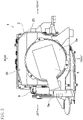
- FIG. 1 illustrates a vehicle air-conditioning air blower 1 according to an embodiment of the present invention, as viewed from the rear side of a vehicle.
- FIG. 2 illustrates the vehicle air-conditioning air blower 1, as viewed from the left side of the vehicle.
- FIG. 3 illustrates the vehicle air-conditioning air blower 1, as viewed from the lower side of the vehicle.
- This vehicle air-conditioning air blower 1 is disposed in, for example, a cabin of an automobile to blow air-conditioning air, and forms a vehicle air conditioner together with an air conditioning unit (not shown) and a refrigeration cycle system.
- the air conditioning unit includes, for example, a cooling heat exchanger serving as an evaporator of a refrigeration cycle, a heating heat exchanger serving as a heater core, an air mixing damper, a blowing direction switching damper, and an air-conditioning casing housing these components.
- Air-conditioning air blown from the vehicle air-conditioning air blower 1 is introduced into the air-conditioning casing, and passes through the cooling heat exchanger and the heating heat exchanger to generate air-conditioned wind having an intended temperature. Then, the air-conditioned wind is fed to areas inside the cabin in accordance with a blowout mode selected by the blowing direction switching damper.
- the temperature of the air-conditioned wind is adjusted by the amount of air which passes through the heating heat exchanger which is determined by the air mixing damper.
- front, rear, left, and right sides of the vehicle will be simply referred to as the "front,” “rear,” “left,” and “right,” respectively.
- the vehicle air-conditioning air blower 1 is housed in an instrument panel (not shown) arranged in a front end portion of the cabin of the vehicle together with the air conditioning unit.
- the air conditioning unit is disposed in a substantially laterally central portion of the interior of the instrument panel, while the vehicle air-conditioning air blower 1 is disposed inside the instrument panel on the passenger's side of the air conditioning unit (on the left side of the air conditioning unit in the case of a right-hand drive vehicle, or on the right side thereof in the case of a left-hand drive vehicle).
- This embodiment illustrates a situation where the vehicle air-conditioning air blower 1 is disposed in a right portion of the vehicle.
- this vehicle air-conditioning air blower 1 has a structure bilaterally symmetrical to that of the vehicle air-conditioning air blower 1 according to this embodiment. Thus, this situation will not be described in detail.
- the vehicle including the vehicle air-conditioning air blower 1 includes a dashboard (a partition member) for separating an engine compartment and the cabin from each other.
- the engine compartment is formed in a front portion of the vehicle, and includes an engine, a transmission, and other components.
- the dashboard extends in a substantially top-to-bottom direction.
- a cowl extending in a lateral direction is disposed on an upper portion of the dashboard.
- the cowl has a communication port communicating with the outside of the cabin.
- the cowl is disposed outside the cabin,. Thus, rainwater, car-washing water, snow, and any other substances may enter the cowl.
- the vehicle air-conditioning air blower 1 includes a blowing casing 2, a blower fan 3, a motor 5 for rotationally driving the blower fan 3, a first inside/outside air switching damper 6, a second inside/outside air switching damper 7, an air filter 8, and an inside/outside air switching actuator 9 (illustrated in FIGS. 1 and 2 ).
- the blower fan 3, the first and second inside/outside air switching dampers 6 and 7, and the air filter 8 are housed in the blowing casing 2.
- An upper portion of the blowing casing 2 has front and rear inside air inlets 2a and 2b illustrated in FIG. 2 and other figures, and an outside air inlet 2c illustrated in FIG. 4 .
- the front inside air inlet 2a is formed through a portion of the upper portion of the blowing casing 2 closer to the front end of the blowing casing 2 than a central portion thereof in the front-to-rear direction, and opens to the interior of the cabin.
- the rear inside air inlet 2b is formed through a portion of the upper portion of the blowing casing 2 closer to the rear end of the blowing casing 2 than the central portion thereof in the front-to-rear direction, and opens to the interior of the cabin.
- Air in the cabin can be introduced into the blowing casing 2 through the front and rear inside air inlets 2a and 2b.
- the upper portion of the blowing casing 2 has an outside air inlet duct portion 2d integrated with the blowing casing 2 to bulge upward from a portion of the blowing casing 2 between the front and rear inside air inlets 2a and 2b.
- An upper portion of the outside air inlet duct portion 2d extends forward.
- the outside air inlet 2c opens through a front end of the outside air inlet duct portion 2d.
- the outside air inlet duct portion 2d is connected to the cowl.
- the outside air inlet 2c communicates with the outside of the cabin through the cowl. Air outside the cabin (outside air) can be introduced into the blowing casing 2 through the outside air inlet 2c.
- the filter 8 is housed in a portion of the interior of the blowing casing 2 below the front and rear inside air inlets 2a and 2b and the outside air inlet 2c.
- the filter 8 is formed in the shape of a plate, and extends horizontally.
- a peripheral portion of the filter 8 is supported by filter support portions 2e provided inside the blowing casing 2.
- a rear wall portion of the blowing casing 2 has a filter insertion hole 2f through which the filter 8 is to be inserted into the blowing casing 2.
- the filter insertion hole 2f is closed by a lid portion 8a provided for a rear end portion of the filter 8.
- the filter 8 may be made of, for example, a commonly-used nonwoven fabric.
- a partition wall portion 2g is provided above the filter 8 inside the blowing casing 2.
- the partition wall portion 2g extends in the top-to-bottom direction, and is slightly inclined rearward toward its lower end portion.
- An upper portion of the interior of the blowing casing 2 has a first air passage R1 in front of the partition wall portion 2g, and a second air passage R2 behind the partition wall portion 2g.
- the width of the first air passage R1 in the front-to-rear direction is set to be greater than that of the second air passage R2 in the front-to-rear direction, and the cross-sectional area of the first air passage R1 is larger than that of the second air passage R2.
- An upstream end portion (upper end portion) of the first air passage R1 communicates with the front inside air inlet 2a and the outside air inlet 2c.
- An upstream end portion (upper end portion) of the second air passage R2 communicates with the rear inside air inlet 2b and the outside air inlet 2c.
- the first and second air passages R1 and R2 communicate with the common outside air inlet 2c, while communicating with the separate inside air inlets 2a and 2b, respectively. This allows inside air and outside air to be introduced into both of the first and second air passages R1 and R2.
- the first inside/outside air switching damper 6 is disposed in front of the partition wall portion 2g inside the blowing casing 2, and includes a closing plate portion 6a, a shaft portion 6b, and end plate portions 6c.
- the closing plate portion 6a extends in the lateral direction.
- the shaft portion 6b also extends in the lateral direction, and is pivotably supported by both lateral side wall portions of the blowing casing 2.
- the end plate portions 6c are respectively provided near both lateral ends of the shaft portion 6b.
- the end plate portions 6c extend radially from the shaft portion 6b, and are respectively arranged adjacent to the lateral end portions of the closing plate portion 6a.
- the closing plate portion 6a, the shaft portion 6b, and the end plate portions 6c are integrated together.
- the first inside/outside air switching damper 6 turns around the center line of the shaft portion 6b. This allows switching to be made between the state where the first inside/outside air switching damper 6 has turned forward as illustrated in FIG. 4 and the state where the first inside/outside air switching damper 6 has turned rearward although not shown. If the first inside/outside air switching damper 6 has turned forward, the front inside air inlet 2a is closed, and the outside air inlet 2c is opened. This prevents the inside air from flowing into the blowing casing 2, and allows the outside air to be introduced into the upstream end portion of the first air passage R1.
- the front inside air inlet 2a is opened, and the outside air inlet 2c is closed. This prevents the outside air from flowing into the blowing casing 2, and allows the inside air to be introduced into the upstream end portion of the first air passage R1.
- the second inside/outside air switching damper 7 is disposed behind the partition wall portion 2g inside the blowing casing 2, and includes a closing plate portion 7a, a shaft portion 7b, and end plate portions 7c, just like the first inside/outside air switching damper 6.
- the second inside/outside air switching damper 7 turns around the center line of the shaft portion 7b. This allows switching to be made between the state where the second inside/outside air switching damper 7 has turned rearward as illustrated in FIG. 4 and the state where the second inside/outside air switching damper 7 has turned forward although not shown. If the second inside/outside air switching damper 7 has turned rearward, the rear inside air inlet 2b is closed, and the outside air inlet 2c is opened.
- the first and second inside/outside air switching dampers 6 and 7 are driven by the inside/outside air switching actuator 9 illustrated in FIGS. 1 , 2 , and other figures.
- the inside/outside air switching actuator 9 is controlled by an air-conditioning control apparatus.
- a link member 9a engages with the shaft portion 6b of the first inside/outside air switching damper 6 and the shaft portion 7b of the second inside/outside air switching damper 7, and is turned by the inside/outside air switching actuator 9 to allow the first and second inside/outside air switching dampers 6 and 7 to work together. Since a well-known technique can be used for the structure in which the first and second inside/outside air switching dampers 6 and 7 work together using the link member 9a, the structure will not be described in detail. Further, the first and second inside/outside air switching dampers 6 and 7 may be separately driven without using the link member 9a.
- the first and second inside/outside air switching dampers 6 and 7 are driven as follows. Specifically, as illustrated in FIG. 4 , an optional one of three modes, i.e., an outside-air introduction mode, an inside-air circulation mode, and an inside-outside air double flow mode, can be selected.
- an optional one of three modes i.e., an outside-air introduction mode, an inside-air circulation mode, and an inside-outside air double flow mode.
- the outside-air introduction mode the first inside/outside air switching damper 6 is turned forward, and the second inside/outside air switching damper 7 is turned rearward.
- the inside-air circulation mode the first inside/outside air switching damper 6 is turned rearward, and the second inside/outside air switching damper 7 is turned forward.
- the inside/outside-air double flow mode the first inside/outside air switching damper 6 is turned forward, and the second inside/outside air switching damper 7 is turned forward.
- the outside-air introduction mode since the first inside/outside air switching damper 6 turns forward, and the second inside/outside air switching damper 7 turns rearward, only outside air is introduced into the first and second air passages R1 and R2.
- the inside-air circulation mode since the first inside/outside air switching damper 6 turns rearward, and the second inside/outside air switching damper 7 turns forward, only inside air is introduced into the first and second air passages R1 and R2.
- the inside-outside air double flow mode since the first inside/outside air switching damper 6 turns forward, and the second inside/outside air switching damper 7 turns forward, outside air is introduced into the first air passage R1, and inside air is introduced into the second air passage R2.
- the inside-outside air double flow mode is used during heating.
- Switching is made among the inside-air circulation mode, the outside-air introduction mode, and the inside-outside air double flow mode by a well-known automatic air-conditioning control technique. Selecting the inside-outside air double flow mode allows outside air, which is relatively dry in winter, to be fed to a defrost outlet to successfully defog a windshield glass, and allows relatively warm inside air to be fed to a heat outlet to improve heating efficiency.
- a scroll casing 20 housing the blower fan 3 is provided below the inside air inlets 2a and 2b and the outside air inlet 2c of the blowing casing 2.
- the scroll casing 20 is divided into an upper scroll casing 21 in which a portion of the blower fan 3 provided with upper blades (first blades) 30 is housed, and a lower scroll casing 22 in which a portion of the blower fan 3 provided with lower blades (second blades) 31 is housed.
- a lower portion of the upper scroll casing 21 and an upper portion of the lower scroll casing 22 are fitted to each other, thereby integrating the upper and lower scroll casings 21 and 22 together.
- the upper and lower blades 30 and 31 may also be referred to as "blades.”
- a bottom wall member 23 is provided for a lower portion of the scroll casing 20.
- the bottom wall member 23 is a component of the scroll casing 20.
- the upper scroll casing 21, the lower scroll casing 22, and the bottom wall member 23 form the scroll casing 20.
- a partition plate 24 that partitions the interior of the scroll casing 20 into upper and lower spaces is disposed inside the scroll casing 20, and is also a component of the scroll casing 20.
- the partition plate 24 has a through hole 24a.
- An upper wall portion of the upper scroll casing 21 has a substantially circular first bell mouth orifice 21a that opens to the interior of the blowing casing 2.
- the first bell mouth orifice 21a faces a lower surface of the filter 8, and communicates with the first air passage R1.
- the upper wall portion of the upper scroll casing 21 is provided with a protruding wall portion 21b protruding upward.
- the protruding wall portion 21b is positioned behind the edge of the first bell mouth orifice 21a, and extends in the lateral direction.
- An upper end of the protruding wall portion 21b reaches an area near the lower end portion of the partition wall portion 2g.
- the protruding wall portion 21b and the partition wall portion 2g partition a portion of the interior of the blowing casing 2 above the upper scroll casing 21 into front and rear spaces.
- the first air passage R1 is formed in front of the protruding wall portion 21b and the partition wall portion 2g
- the second air passage R2 is formed behind the protruding wall portion 21b and the partition wall portion 2g.
- the first air passage R1 communicates with the interior of the upper scroll casing 21 through the first bell mouth orifice 21a.
- the interior of the upper scroll casing 21 serves as a portion of the first air passage R1.
- a portion of the blowing casing 2 above the partition plate 24 is defined as the first air passage R1.
- a portion of the blower fan 3 provided with the upper blades 30 is disposed in the first air passage R1 inside the upper scroll casing 21.
- the blower fan 3 rotating inside the upper scroll casing 21 allows the portion of the blower fan 3 provided with the upper blades 30 to send air in the first air passage R1 as air-conditioning air.
- the portion of the blower fan 3 provided with the upper blades 30 is a portion of the blower fan 3 that forms an upper one of air flows.
- a front portion of a left side wall portion of the upper scroll casing 21 has an upper air outlet 21c connected to the air conditioning unit.
- a downstream end of the first air passage R1 communicates with the upper air outlet 21c, and air in the first air passage R1 is blown out of the upper air outlet 21c to the outside of the upper scroll casing 21.
- the second air passage R2 extends downward through a rear portion of the interior of the upper scroll casing 21, and a lower end portion of the second air passage R2 reaches the bottom wall member 23.
- a lower wall portion of the lower scroll casing 22 is spaced apart upward from the bottom wall member 23, and the lower end portion of the second air passage R2 is located between the lower wall portion of the lower scroll casing 22 and the bottom wall member 23.
- the lower wall portion of the lower scroll casing 22 is provided with a bell mouth component 22b having a substantially circular second bell mouth orifice 22a.
- the second bell mouth orifice 22a faces the bottom wall member 23, and communicates with the lower end portion of the second air passage R2.
- the second bell mouth orifice 22a is positioned concentrically with the first bell mouth orifice 21a.
- the bell mouth component 22b is fitted into a peripheral portion of an opening 22c of the lower wall portion of the lower scroll casing 22.
- the lower end portion of the second air passage R2 communicates with the interior of the lower scroll casing 22 through the second bell mouth orifice 22a.
- the interior of the lower scroll casing 22 serves as a portion of the second air passage R2.
- a portion of the lower scroll casing 22 below the partition plate 24 is defined as a portion of the second air passage R2.
- a portion of the blower fan 3 provided with the lower blades 31 is disposed in the second air passage R2 inside the lower scroll casing 22.
- the blower fan 3 rotating allows the portion of the blower fan 3 provided with the lower blades 31 to send air in the second air passage R2 as air-conditioning air.
- the portion of the blower fan 3 provided with the lower blades 31 is a portion of the blower fan 3 that forms a lower one of the air flows.
- a front portion of a left side wall portion of the lower scroll casing 22 has a lower air outlet 22c connected to the air conditioning unit.
- the lower air outlet 22c is located directly below the upper air outlet 21c.
- a downstream end of the second air passage R2 communicates with the lower air outlet 22c, and air in the second air passage R2 is blown out of the lower air outlet 22c to the outside of the lower scroll casing 22.
- the bottom wall member 23 covers a lower end portion of the lower scroll casing 22, and is a cover-like member that covers the lower end portion.
- a peripheral portion of the bottom wall member 23 is formed to be fitted to a peripheral portion of the lower end portion of the lower scroll casing 22 to prevent air from leaking from the gap between the peripheral portion of the bottom wall member 23 and the peripheral portion of the lower end portion of the lower scroll casing 22.
- a motor 5 is attached to the bottom wall member 23 via a motor attachment member 5a.
- the blower fan 3 is disposed above the motor 5.
- the motor attachment member 5a is fixed to the bottom wall member 23.
- the motor 5 is attached to the motor attachment member 5a.
- the motor 5 includes a body 5b including a rotor and other components, a rotation shaft 5c extending in the top-to-bottom direction, and a cover 5d covering the body 5b from above.
- the rotation shaft 5c protrudes upward from an upper end of the body 5b, passes through the cover 5d, and further protrudes upward beyond the cover 5d.
- the rotation shaft 5c is disposed concentrically with the first and second bell mouth orifices 21a and 22a. An upper end portion of the rotation shaft 5c is located above the second bell mouth orifice 22a.
- the cover 5d has a cylindrical portion 5e surrounding the rotation shaft 5c.
- the cylindrical portion 5e may be circular cylindrical, and is disposed concentrically with the rotation shaft 5c. Instead of the cylindrical portion 5e, a plurality of arc-shaped wall portions may be provided.
- the rotation shaft 5c protrudes upward beyond an upper end of the cylindrical portion 5e.
- the blower fan 3 is fixed to the rotation shaft 5c, and rotates together with the rotation shaft 5c.
- a voltage applied to the body 5b of the motor 5 brings a turning force of the rotation shaft 5c to be transferred to the blower fan 3.
- the body 5b of the motor 5 is connected to an air-conditioning control apparatus (not shown), which applies a voltage to the body 5b so that the motor 5 rotates at an intended rotational speed.
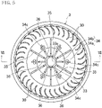
- the blower fan 3 includes a fixed portion 33 fixed to the rotation shaft 5c of the motor 5, a cone portion 34 extending from the fixed portion 33 in a radial direction of the rotation shaft 5c, and many upper blades 30 and many lower blades 31 fixed to a radially outer portion of the cone portion 34.
- the fixed portion 33, the cone portion 34, and the upper and lower blades 30 and 31 may be an integrally molded product made of a resin material. However, they may be separate members combined together.
- the blower fan 3 is a centrifugal fan.
- the fixed portion 33 is formed in the shape of a cylinder having an insertion hole 33a into which the rotation shaft 5c of the motor 5 is inserted.
- An upper portion of the fixed portion 33 protrudes upward from an upper surface of an inner peripheral portion 34b of the cone portion 34, and is thus positioned to protrude toward the inside of the cone portion 34.
- the insertion hole 33a of the fixed portion 33 extends in the top-to-bottom direction, and has upper and lower ends both opened.
- the rotation shaft 5c of the motor 5 is fixed while being inserted into the insertion hole 33a.
- a means to fix the fixed portion 33 to the rotation shaft 5c of the motor 5 has been known in the art. Thus, the means will not be described in detail.
- the cone portion 34 is recessed downward.
- the cone portion 34 has an outer peripheral portion 34a and the inner peripheral portion 34b, which are integrated together.
- the inner peripheral portion 34b extends radially outward from a vertically intermediate portion of the outer peripheral surface of the fixed portion 33, and is inclined or curved downward toward the radially outer end of the inner peripheral portion 34b.
- the outer peripheral portion 34a extends upward from the radially outer end of the inner peripheral portion 34b, and is inclined or curved radially outward toward the upper end of the outer peripheral portion 34a.
- the shapes of the outer and inner peripheral portions 34a and 34b are merely examples.
- the outer and inner peripheral portions 34a and 34b may be smoothly continuous, or may be continuous such that the boundary between the outer and inner peripheral portions 34a and 34b is clearly visible.
- the outer and inner peripheral portions 34a and 34b form the cone portion 34 recessed downward.
- the cone portion 34 forms a shape that can also be referred to as a "bowl” shape or a "concave” shape, for example.
- An upper end portion of the outer peripheral portion 34a of the cone portion 34 extends radially outward. This extending portion extends in a direction substantially orthogonal to the rotation shaft 5c of the motor 5. Further, the lower end of the outer peripheral portion 34a is the lowest portion of the cone portion 34.
- Lower end portions of the upper blades 30 are coupled to an upper surface of the extending portion of the outer peripheral portion 34a of the cone portion 34, and extend upward from the upper surface.
- Upper end portions of the lower blades 31 are coupled to a lower surface of the extending portion of the outer peripheral portion 34a of the cone portion 34, and extend downward from the lower surface.
- Rotation of the blower fan 3 allows air to be sucked from above the upper blades 30 to be blown radially out of the gap between each circumferentially adjacent pair of the upper blades 30, and allows air to be sucked from below the lower blades 31 to be blown radially out of the gap between each circumferentially adjacent pair of the lower blades 31.
- the cone portion 34 has a plurality of drainage holes 34c through which water on an upper surface of the cone portion 34 is drained downward of the cone portion 34.
- the drainage holes 34c are formed at the lower end of the outer peripheral portion 34a of the cone portion 34, i.e., through the lowest portion of the cone portion 34, and are spaced apart from one another in the circumferential direction of the rotation shaft 5c.
- the inner peripheral portion 34b can be inclined downward toward the radially outer end of the inner peripheral portion 34b, and is thus shaped to be inclined downward toward lower edge portions of the drainage holes 34c. This makes it easy for water on the upper surface of the inner peripheral portion 34b to flow toward the drainage holes 34c.
- drainage holes 34c can be arranged at regular intervals.
- the drainage holes 34c are apart upward from the upper end of the cylindrical portion 5e of the cover 5d, and are positioned radially outward of the cylindrical portion 5e. Thus, the drainage holes 34c are located outside the cylindrical portion 5e in a plan view.
- first and second ribs 35 and 36 that extend in the radial direction of the rotation shaft 5c are provided on the upper surface of the cone portion 34.
- the first and second ribs 35 and 36 are connected to the outer peripheral surface of the fixed portion 33, and also connected to the outer peripheral portion 34a of the cone portion 34.
- the first and second ribs 35 and 36 are reinforcing ribs that extend radially from the outer peripheral surface of the fixed portion 33 to the outer peripheral portion 34a of the cone portion 34, and can also be referred to as "coupling ribs" that couple the fixed portion 33 and the outer peripheral portion 34a together.
- the first ribs 35 are above the second ribs 36, and the radial dimension of each of the first ribs 35 is set to be greater than that of each of the second ribs 36.
- the first and second ribs 35 and 36 may have the same thickness, or may have different thicknesses.
- the first and second ribs 35 and 36 are alternately arranged in the circumferential direction of the rotation shaft 5c.
- the lower ends of the first and second ribs 35 and 36 are connected to the inner peripheral portion 34b of the cone portion 34.
- the fixed portion 33, the inner peripheral portion 34b of the cone portion 34, and the outer peripheral portion 34a of the cone portion 34 are coupled together through the first and second ribs 35 and 36 to be integrated together.
- the second ribs 36 are respectively disposed to cross the drainage holes 34c.
- the second ribs 36 each pass through a central portion of an opening of an associated one of the drainage holes 34c in the width direction of the opening.
- each second rib 36 is disposed astride the associated drainage hole 34c, which is separated into two portions by the central portion of the opening of the associated drainage hole 34c in the width direction of the opening.
- Arranging the second ribs 36 as described above allows the openings of the associated drainage holes 34c to be positioned to be unclosed.
- the first ribs 35 are each spaced apart from the opening of an associated one of the drainage holes 34c.
- the first ribs 35 are also positioned to allow the openings of the associated drainage holes 34c to be unclosed. Note that both or either of the first ribs 35 or the second ribs 36 may be omitted.
- the upper ends of the first and second ribs 35 and 36 are positioned below the lower ends of the upper blades 30. This makes it difficult for the first and second ribs 35 and 36 to hinder the air flows. Thus, a sufficient volume of air is allowed to flow.
- the first ribs 35 are arranged at regular intervals in the circumferential direction of the rotation shaft 5c.
- the second ribs 36 are also arranged at regular intervals in the circumferential direction of the rotation shaft 5c.
- the intervals between adjacent ones of the first and second ribs 35 and 36 in the circumferential direction of the rotation shaft 5c are all set to be equal.
- the blower fan 3 is highly balanced while rotating.
- the vehicle air-conditioning air blower 1 of this embodiment when the inside air inlets 2a and 2b are opened, and the outside air inlet 2c is closed by operations of the inside/outside air switching dampers 6 and 7, the vehicle air-conditioning air blower 1 operates in the inside-air circulation mode in which inside air is introduced through the inside air inlets 2a and 2b thereinto.
- the blower fan 3 rotating allows the inside air introduced through the inside air inlets 2a and 2b to flow through the first and second air passages R1 and R2 and to be then sent as air-conditioning air.
- the vehicle air-conditioning air blower 1 When the inside air inlets 2a and 2b are closed, and the outside air inlet 2c is opened by operations of the inside/outside air switching dampers 6 and 7, the vehicle air-conditioning air blower 1 operates in the outside-air introduction mode in which outside air is introduced through the outside air inlet 2c thereinto. In the outside-air introduction mode, the blower fan 3 rotating allows the outside air introduced through the outside air inlet 2c to flow through the first and second air passages R1 and R2 and to be then sent as air-conditioning air.
- the vehicle air-conditioning air blower 1 operates in the inside-outside air double flow mode.
- the blower fan 3 rotating allows the outside air introduced through the outside air inlet 2c to flow through the first air passage R1, and allows the inside air introduced through the inside air inlets 2a and 2b to flow through the second air passage R2.
- a combination of the outside air and the inside air is sent as air-conditioning air.
- the vehicle air-conditioning air blower 1 according to this embodiment can select an optional one of the outside-air introduction mode, the inside-air circulation mode, and the inside-outside air double flow mode, to send air in the selected mode.
- rainwater or car-washing water may enter the interior of the scroll casing 20 through the outside air inlet 2c. If water enters the interior of the scroll casing 20, the water may reach the upper surface of the cone portion 34 of the blower fan 3. If the water reaches the upper surface of the cone portion 34, which has the drainage holes 34c, the water is drained downward of the cone portion 34 through the drainage holes 34c. Thus, the water is less likely to remain accumulated on the upper surface of the cone portion 34. At this time, the water that has reached the upper surface of the cone portion 34 flows toward the lowest portion of the cone portion 34. However, since the lowest portion of the cone portion 34 has the drainage holes 34c, the water becomes much less likely to remain accumulated on the upper surface of the cone portion 34.
- a lower surface of a cone portion 34 may have a plurality of projections 34d each projecting downward from inner ends of associated ones of drainage holes 34c in a radial direction of the rotation shaft 5c. This makes it easy for water flowing downward from the drainage holes 34c to flow along the projections 34d. Since the projections 34d project from the inner ends of the associated drainage holes 34c in the radial direction of the rotation shaft 5c, water is less likely to flow in a direction that allows the water to be closer to the rotation shaft 5c. This reduces water entering the motor 5.
- the projections 34d extend in the circumferential direction of the rotation shaft 5c.
- the projections 34d can be arranged at regular intervals in the circumferential direction of the rotation shaft 5c.
- the projections 34d can also extend like an arc concentric with the rotation shaft 5c.
- the projections 34d are each located directly below associated ones of the first and second ribs 35 and 36. Since the projections 34d extend circumferentially, each of the projections 34d is located at the same position as a portion of the cone portion 34 where an associated one of the first ribs 35 is formed and a portion of the cone portion 34 where an associated one of the second ribs 36 is formed. Further, each projection 34d overlaps with the associated first and second ribs 35 and 36 in the thickness direction (vertical direction) of the cone portion 34. This further improves the rigidity of the cone portion 34.
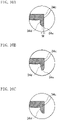
- the width W of a lower end surface 34e of each projection 34d can be 1.0 mm or less. This facilitates dropping water that has flowed along the projection 34d to the lower end surface 34e.
- a lower end surface 34e of each of projections 34d may be curved.
- each of projections 34d may be pointed downward.
- the second and third variations also facilitate dropping water that has flowed along the projections 34d.
- projections 34d may have ends each having a protruding portion 34f protruding radially outward. This can reduce water flowing radially inwardly from a space between each circumferentially adjacent pair of the projections 34d.
- a ring-shaped projection 34d continuous in a circumferential direction of the rotation shaft 5c may be provided.
- an outer peripheral portion 34a of a cone portion 34 of a blower fan 3 may have a vertical plate portion 37 and a horizontal plate portion 38.
- the vertical plate portion 37 extends downward from a lower surface of the outer peripheral portion 34a of the cone portion 34, and has a ring shape.
- the horizontal plate portion 38 extends radially outward from the lower end of the vertical plate portion 37. The upper ends of lower blades 31 are coupled to a lower surface of the horizontal plate portion 38.
- a vehicle air-conditioning air blower may be used, for example, as an air blower unit for a vehicle air conditioner.
Landscapes
- Engineering & Computer Science (AREA)
- Mechanical Engineering (AREA)
- General Engineering & Computer Science (AREA)
- Physics & Mathematics (AREA)
- Thermal Sciences (AREA)
- Air-Conditioning For Vehicles (AREA)
- Structures Of Non-Positive Displacement Pumps (AREA)
Description
- The present invention relates to vehicle air-conditioning air blowers each mounted on an automobile, for example, to blow air-conditioning air, and more particularly relates to a structure that drives a blower fan through a motor disposed below the blower fan.
- Typically, an air conditioner mounted on a vehicle selects either air inside a cabin (inside air) or air outside the cabin (outside air) to blow the selected air as air-conditioning air, and the blown air has its temperature controlled by a cooling heat exchanger and a heating heat exchanger, and is then fed to areas inside the cabin.
- Recently commercialized vehicle air-conditioning air blowers for blowing air-conditioning air include a device that is switchable among not only an inside-air circulation mode in which only the inside air is blown, and an outside-air introduction mode in which only the outside air is blown, but also an inside-outside air double flow mode in which both inside air and outside air are blown. That is to say, as disclosed in
JP2000-296710 JP2001-206044 JP2011-201501 JP2015-67260 - A vehicle air-conditioning air blower of
JP2015-67260 - The scroll casing includes therein a partition plate extending horizontally through a vertically intermediate portion of the scroll casing. The partition plate partitions the interior of the scroll casing into upper and lower air passages. A peripheral portion of the partition plate is vertically sandwiched between the lower portion of the upper scroll casing and the upper portion of the lower scroll casing.
-
WO 2017/163631 discloses a blower device for air-conditioning of vehicle comprising drainage holes on a peripheral wall surrounding the output shaft of the motor.EP 2381110 andJP 2015-183578 - The blower fan has a fixed portion to be fixed to a rotation shaft of the motor, and a portion called a cone portion extending from the fixed portion to its surrounding blades. The cone portion may be recessed downward. Specifically, the motor having a long rotation shaft is less likely to be reliably stable while rotating. Thus, there is a need to shorten the rotation shaft. To shorten the rotation shaft, the fixed portion of the blower fan needs to be positioned at a lower position. On the other hand, the positions of the blades are determined by the position of the scroll casing. Thus, to shorten the rotation shaft of the motor, a central portion of the cone portion needs to be positioned below an outer peripheral portion of the cone portion. Thus, a need arises to position the fixed portion at a lower position.
- However, if the cone portion is recessed downward as described above, rainwater or car-washing water entering the scroll casing through the outside air inlet, for example, may be accumulated on a recessed upper surface of the cone portion. This water may cause a malfunction.
- In view of the foregoing background, it is therefore an object of the present invention to eliminate or reduce water accumulated on a cone portion to reduce malfunctions.
- In order to achieve the foregoing object, in the present invention, the lowest portion of a cone portion has a drainage hole. This allows water accumulated on an upper surface of the cone portion to be drained downward of the cone portion.
- The invention is defined by
claim 1. and is directed to a vehicle air-conditioning air blower. The vehicle air-conditioning air blower includes: a casing having an inside air inlet through which air in a cabin is introduced into the casing, and an outside air inlet through which air outside the cabin is introduced into the casing, the casing housing an inside/outside air switching damper that opens and closes the inside air inlet and the outside air inlet; a blower fan disposed in the casing; and a motor including a rotation shaft extending in a top-to-bottom direction. The blower fan is disposed above the motor. The blower fan includes a fixed portion fixed to the rotation shaft, a cone portion extending from the fixed portion in a radial direction of the rotation shaft, and at least one blade fixed to a radially outer surface of the cone portion. The cone portion is recessed downward. A lowest portion of the cone portion has a drainage hole through which water on an upper surface of the cone portion is drained downward of the cone portion. - This configuration allows rainwater or car-washing water, for example, entering the interior of the casing through the outside air inlet to reach the upper surface of the cone portion, which has the drainage hole, to be drained downward of the cone portion through the drainage hole. Thus, the water accumulated on the upper surface of the cone portion is less likely to remain. Specifically, the water that has reached the upper surface of the cone portion flows toward the lowest portion of the cone portion. However, since the lowest portion of the cone portion has the drainage hole, the water on the upper surface of the cone portion is easily drained.
- Accordingly, a cone portion has the lowest portion having a drainage hole through which water on an upper surface of the cone portion is drained downward of the cone portion. This makes it difficult for water accumulated on the upper surface of the cone portion to remain, and can thus reduce malfunctions
- The cone portion is inclined downward toward a lower edge portion of the drainage hole.
- This configuration allows water on the upper surface of the cone portion to flow toward the lower edge portion of the drainage hole.
- Accordingly, the water on the upper surface of the cone portion can flow toward the drainage hole.
- The casing has therein first and second air passages each communicating with both of the inside air inlet and the outside air inlet, the blower fan includes the at least one blade including a first blade disposed in the first air passage, and a second blade disposed in the second air passage, the first blade being used to send air in the first air passage as air-conditioning air, the second blade being used to send air in the second air passage as air-conditioning air, and the first and second blades are coupled to the cone portion.
- With this configuration, if an operation of the inside/outside air switching damper allows the inside air inlet to open, and allows the outside air inlet to close, the vehicle air-conditioning air blower operates in the inside-air circulation mode in which inside air is introduced through the inside air inlet thereinto. In the inside-air circulation mode, the blower fan rotating allows the inside air introduced through the inside air inlet to flow through the first and second air passages and to be then sent as air-conditioning air. If an operation of the inside/outside air switching damper allows the inside air inlet to close, and allows the outside air inlet to open, the vehicle air-conditioning air blower operates in the outside-air introduction mode in which outside air is introduced through the outside air inlet thereinto. In the outside-air introduction mode, the blower fan rotating allows the outside air introduced through the outside air inlet to flow through the first and second air passages and to be then sent as air-conditioning air.
- Accordingly, any of an outside-air introduction mode, an inside-air circulation mode, and an inside-outside air double flow mode can be selected, to send air in the selected mode.
- A lower surface of the cone portion may have at least one projection projecting downward from an inner end of the drainage hole in the radial direction of the rotation shaft (not part of the claimed invention).
- This configuration makes it easy for water flowing downward from the drainage hole to flow along the projection. Since the projection projects from the inner end of the drainage hole in the radial direction of the rotation shaft, water is less likely to flow in a direction that allows the water to be closer to the rotation shaft. This reduces water entering the motor.
- Accordingly, the lower surface of the cone portion is provided with at least one projection that projects downward from the inner end of the drainage hole in a radial direction of a rotation shaft. Thus, water flowing downward from the drainage hole is less likely to flow in a direction that allows the water to be closer to the rotation shaft. This can reduce water entering a motor.
- The at least one projection may extend in a circumferential direction of the rotation shaft (not part of the claimed invention).
- This configuration makes it difficult for water flowing downward from the drainage hole to flow in the direction that allows the water to be closer to the rotation shaft.
- Accordingly, the projection extends in a circumferential direction of the rotation shaft. This can substantially prevent the water flowing downward from the drainage hole from flowing in the direction that allows the water to be closer to the rotation shaft.
- The at least one projection may include a plurality of projections arranged at regular intervals in the circumferential direction of the rotation shaft (not part of the claimed invention).
- This configuration makes it possible for the blower fan to be highly balanced while rotating.
- Accordingly, the projection includes a plurality of projections arranged at regular intervals in the circumferential direction of the rotation shaft. Thus, the blower fan can be highly balanced while rotating.
- A lower end surface of the at least one projection may have a width of 1.0 mm or less (not part of the claimed invention).
- This configuration makes it possible for water that has reached the lower end surface of the projection to easily drop directly downward.
- Accordingly, the width of a lower end surface of the one projection is 1.0 mm or less. This makes it easy for water that has reached the lower end surface of the projection to drop directly downward. This can substantially prevent the water flowing downward from the drainage hole from flowing in the direction that allows the water to be closer to the rotation shaft.
- A lower portion of the at least one projection may be pointed downward (not part of the claimed invention).
- This configuration makes it possible for water that has reached the lower portion of the projection to easily drop directly downward.
- Accordingly, a lower portion of the projection is pointed downward. This makes it easy for water that has reached the lower portion of the projection to drop directly downward. This can substantially prevent the water flowing downward from the drainage hole from flowing in the direction that allows the water to be closer to the rotation shaft.
- The at least one projection may extend like an arc concentric with the rotation shaft (not part of the claimed invention).
- Accordingly, the projection extends like an arc concentric with the rotation shaft. Thus, the projection can function as an arc-shaped rib. This can increase the rigidity of the cone portion.
- The motor may include a body, and a cover that covers the body from above, the rotation shaft may pass through the cover to protrude upward from an upper end of the body, the cover may have a cylindrical portion surrounding the rotation shaft, and the drainage hole may be apart upward from an upper end of the cylindrical portion, and may be positioned radially outward of the cylindrical portion.
- With this configuration, if the body of the motor is covered with the cover, the drainage hole is located radially outward of the cylindrical portion of the cover. Thus, water dropped from the drainage hole flows outside the cylindrical portion. This reduces water entering the body.
- Accordingly, water dropped from the drainage hole can be substantially prevented from entering a body of the motor.
- The cone portion may be provided with a rib extending in the radial direction of the rotation shaft, and the rib may cross the drainage hole.
- This configuration reduces the degree to which the rigidity of the cone portion having the drainage hole decreases.
- Accordingly, the degree to which the rigidity of the cone portion having the drainage hole decreases can be reduced.
- Further, if the inside air inlet and the outside air inlet are opened by an operation of the inside/outside air switching damper, the vehicle air-conditioning air blower operates in the inside-outside air double flow mode to rotate the blower fan. With the rotation, the outside air introduced through the outside air inlet flows through one of the first and second air passages, and the inside air introduced through the inside air inlet flows through the other air passage. Thus, a combination of the outside air and the inside air is sent as air-conditioning air.
-
- [
FIG. 1] FIG. 1 is a back view of a vehicle air-conditioning air blower according to an embodiment of the present invention. - [
FIG. 2] FIG. 2 is a left side view of the vehicle air-conditioning air blower. - [
FIG. 3] FIG. 3 is a bottom view of the vehicle air-conditioning air blower. - [
FIG. 4] FIG. 4 is a cross-sectional view taken along line IV-IV shown inFIG. 1 . - [
FIG. 5] FIG. 5 is a plan view of a blower fan. - [
FIG. 6] FIG. 6 is a cross-sectional view taken along line VI-VI shown inFIG. 5 . - [
FIG. 7] FIG. 7 is a bottom view of the blower fan. - [
FIG. 8] FIG. 8 is a view corresponding toFIG. 6 , illustrating a first variation of the embodiment (not part of the claimed invention). - [
FIG. 9] FIG. 9 is a view corresponding toFIG. 7 , illustrating the first variation of the embodiment (not part of the claimed invention). - [
FIG. 10] FIG. 10A is an enlarged view of a portion A ofFIG. 8 ,FIG. 10B is a view corresponding toFIG. 10A , illustrating a second variation, andFIG. 10C is a view corresponding toFIG. 10A , illustrating a third variation (not part of the claimed invention). - [
FIG. 11] FIG. 11 is a view corresponding toFIG. 7 , illustrating a fourth variation of the embodiment (not part of the claimed invention). - [
FIG. 12] FIG. 12 is a view corresponding toFIG. 7 , illustrating a fifth variation of the embodiment (not part of the claimed invention). - [
FIG. 13] FIG. 13 is a view corresponding toFIG. 6 , illustrating a sixth variation of the embodiment (not part of the claimed invention). - Embodiments of the present invention will now be described in detail with reference to the drawings. The following description of preferred embodiments is only an example in nature, and is not intended to limit the scope, applications, or use of the present invention.
-
FIG. 1 illustrates a vehicle air-conditioning air blower 1 according to an embodiment of the present invention, as viewed from the rear side of a vehicle.FIG. 2 illustrates the vehicle air-conditioning air blower 1, as viewed from the left side of the vehicle.FIG. 3 illustrates the vehicle air-conditioning air blower 1, as viewed from the lower side of the vehicle. This vehicle air-conditioning air blower 1 is disposed in, for example, a cabin of an automobile to blow air-conditioning air, and forms a vehicle air conditioner together with an air conditioning unit (not shown) and a refrigeration cycle system. - The air conditioning unit includes, for example, a cooling heat exchanger serving as an evaporator of a refrigeration cycle, a heating heat exchanger serving as a heater core, an air mixing damper, a blowing direction switching damper, and an air-conditioning casing housing these components. Air-conditioning air blown from the vehicle air-
conditioning air blower 1 is introduced into the air-conditioning casing, and passes through the cooling heat exchanger and the heating heat exchanger to generate air-conditioned wind having an intended temperature. Then, the air-conditioned wind is fed to areas inside the cabin in accordance with a blowout mode selected by the blowing direction switching damper. The temperature of the air-conditioned wind is adjusted by the amount of air which passes through the heating heat exchanger which is determined by the air mixing damper. - In the following description of this embodiment, the front, rear, left, and right sides of the vehicle will be simply referred to as the "front," "rear," "left," and "right," respectively. These definitions are merely prepared for easy understanding, and do not limit how the vehicle air-conditioning air blower is actually used, how the vehicle air-conditioning air blower is actually installed, and how the vehicle air-conditioning air blower is actually assembled.
- The vehicle air-
conditioning air blower 1 is housed in an instrument panel (not shown) arranged in a front end portion of the cabin of the vehicle together with the air conditioning unit. The air conditioning unit is disposed in a substantially laterally central portion of the interior of the instrument panel, while the vehicle air-conditioning air blower 1 is disposed inside the instrument panel on the passenger's side of the air conditioning unit (on the left side of the air conditioning unit in the case of a right-hand drive vehicle, or on the right side thereof in the case of a left-hand drive vehicle). This embodiment illustrates a situation where the vehicle air-conditioning air blower 1 is disposed in a right portion of the vehicle. However, if a vehicle air-conditioning air blower 1 is disposed in a left portion of the vehicle, this vehicle air-conditioning air blower 1 has a structure bilaterally symmetrical to that of the vehicle air-conditioning air blower 1 according to this embodiment. Thus, this situation will not be described in detail. - Although not shown, the vehicle including the vehicle air-
conditioning air blower 1 includes a dashboard (a partition member) for separating an engine compartment and the cabin from each other. The engine compartment is formed in a front portion of the vehicle, and includes an engine, a transmission, and other components. The dashboard extends in a substantially top-to-bottom direction. A cowl extending in a lateral direction is disposed on an upper portion of the dashboard. The cowl has a communication port communicating with the outside of the cabin. The cowl is disposed outside the cabin,. Thus, rainwater, car-washing water, snow, and any other substances may enter the cowl. - As shown also in
FIG. 4 , the vehicle air-conditioning air blower 1 includes a blowingcasing 2, ablower fan 3, amotor 5 for rotationally driving theblower fan 3, a first inside/outsideair switching damper 6, a second inside/outsideair switching damper 7, anair filter 8, and an inside/outside air switching actuator 9 (illustrated inFIGS. 1 and2 ). Theblower fan 3, the first and second inside/outsideair switching dampers air filter 8 are housed in the blowingcasing 2. - An upper portion of the blowing
casing 2 has front and rearinside air inlets FIG. 2 and other figures, and anoutside air inlet 2c illustrated inFIG. 4 . As illustrated inFIG. 2 , the front insideair inlet 2a is formed through a portion of the upper portion of the blowingcasing 2 closer to the front end of the blowingcasing 2 than a central portion thereof in the front-to-rear direction, and opens to the interior of the cabin. The rear insideair inlet 2b is formed through a portion of the upper portion of the blowingcasing 2 closer to the rear end of the blowingcasing 2 than the central portion thereof in the front-to-rear direction, and opens to the interior of the cabin. Air in the cabin (inside air) can be introduced into the blowingcasing 2 through the front and rearinside air inlets - As illustrated in
FIG. 4 , the upper portion of the blowingcasing 2 has an outside airinlet duct portion 2d integrated with the blowingcasing 2 to bulge upward from a portion of the blowingcasing 2 between the front and rearinside air inlets inlet duct portion 2d extends forward. Theoutside air inlet 2c opens through a front end of the outside airinlet duct portion 2d. The outside airinlet duct portion 2d is connected to the cowl. Theoutside air inlet 2c communicates with the outside of the cabin through the cowl. Air outside the cabin (outside air) can be introduced into the blowingcasing 2 through theoutside air inlet 2c. - As illustrated in
FIG. 4 , thefilter 8 is housed in a portion of the interior of the blowingcasing 2 below the front and rearinside air inlets outside air inlet 2c. Thefilter 8 is formed in the shape of a plate, and extends horizontally. A peripheral portion of thefilter 8 is supported byfilter support portions 2e provided inside the blowingcasing 2. A rear wall portion of the blowingcasing 2 has afilter insertion hole 2f through which thefilter 8 is to be inserted into the blowingcasing 2. Thefilter insertion hole 2f is closed by alid portion 8a provided for a rear end portion of thefilter 8. Note that thefilter 8 may be made of, for example, a commonly-used nonwoven fabric. - A
partition wall portion 2g is provided above thefilter 8 inside the blowingcasing 2. Thepartition wall portion 2g extends in the top-to-bottom direction, and is slightly inclined rearward toward its lower end portion. An upper portion of the interior of the blowingcasing 2 has a first air passage R1 in front of thepartition wall portion 2g, and a second air passage R2 behind thepartition wall portion 2g. The width of the first air passage R1 in the front-to-rear direction is set to be greater than that of the second air passage R2 in the front-to-rear direction, and the cross-sectional area of the first air passage R1 is larger than that of the second air passage R2. - An upstream end portion (upper end portion) of the first air passage R1 communicates with the front inside
air inlet 2a and theoutside air inlet 2c. An upstream end portion (upper end portion) of the second air passage R2 communicates with the rear insideair inlet 2b and theoutside air inlet 2c. The first and second air passages R1 and R2 communicate with the commonoutside air inlet 2c, while communicating with the separateinside air inlets - The first inside/outside
air switching damper 6 is disposed in front of thepartition wall portion 2g inside the blowingcasing 2, and includes aclosing plate portion 6a, ashaft portion 6b, andend plate portions 6c. Theclosing plate portion 6a extends in the lateral direction. Theshaft portion 6b also extends in the lateral direction, and is pivotably supported by both lateral side wall portions of the blowingcasing 2. Theend plate portions 6c are respectively provided near both lateral ends of theshaft portion 6b. Theend plate portions 6c extend radially from theshaft portion 6b, and are respectively arranged adjacent to the lateral end portions of theclosing plate portion 6a. Theclosing plate portion 6a, theshaft portion 6b, and theend plate portions 6c are integrated together. The first inside/outsideair switching damper 6 turns around the center line of theshaft portion 6b. This allows switching to be made between the state where the first inside/outsideair switching damper 6 has turned forward as illustrated inFIG. 4 and the state where the first inside/outsideair switching damper 6 has turned rearward although not shown. If the first inside/outsideair switching damper 6 has turned forward, the front insideair inlet 2a is closed, and theoutside air inlet 2c is opened. This prevents the inside air from flowing into the blowingcasing 2, and allows the outside air to be introduced into the upstream end portion of the first air passage R1. On the other hand, if the first inside/outsideair switching damper 6 has turned rearward, the front insideair inlet 2a is opened, and theoutside air inlet 2c is closed. This prevents the outside air from flowing into the blowingcasing 2, and allows the inside air to be introduced into the upstream end portion of the first air passage R1. - The second inside/outside
air switching damper 7 is disposed behind thepartition wall portion 2g inside the blowingcasing 2, and includes aclosing plate portion 7a, ashaft portion 7b, andend plate portions 7c, just like the first inside/outsideair switching damper 6. The second inside/outsideair switching damper 7 turns around the center line of theshaft portion 7b. This allows switching to be made between the state where the second inside/outsideair switching damper 7 has turned rearward as illustrated inFIG. 4 and the state where the second inside/outsideair switching damper 7 has turned forward although not shown. If the second inside/outsideair switching damper 7 has turned rearward, the rear insideair inlet 2b is closed, and theoutside air inlet 2c is opened. This prevents the inside air from flowing into the blowingcasing 2, and allows the outside air to be introduced into the upstream end portion of the second air passage R2. On the other hand, if the second inside/outsideair switching damper 7 has turned forward, the rear insideair inlet 2b is opened, and theoutside air inlet 2c is closed. This prevents the outside air from flowing into the blowingcasing 2, and allows the inside air to be introduced into the upstream end portion of the second air passage R2. - The first and second inside/outside
air switching dampers air switching actuator 9 illustrated inFIGS. 1 ,2 , and other figures. Although not shown, the inside/outsideair switching actuator 9 is controlled by an air-conditioning control apparatus. Alink member 9a engages with theshaft portion 6b of the first inside/outsideair switching damper 6 and theshaft portion 7b of the second inside/outsideair switching damper 7, and is turned by the inside/outsideair switching actuator 9 to allow the first and second inside/outsideair switching dampers air switching dampers link member 9a, the structure will not be described in detail. Further, the first and second inside/outsideair switching dampers link member 9a. - In this embodiment, the first and second inside/outside
air switching dampers FIG. 4 , an optional one of three modes, i.e., an outside-air introduction mode, an inside-air circulation mode, and an inside-outside air double flow mode, can be selected. In the outside-air introduction mode, the first inside/outsideair switching damper 6 is turned forward, and the second inside/outsideair switching damper 7 is turned rearward. In the inside-air circulation mode, the first inside/outsideair switching damper 6 is turned rearward, and the second inside/outsideair switching damper 7 is turned forward. In the inside/outside-air double flow mode, the first inside/outsideair switching damper 6 is turned forward, and the second inside/outsideair switching damper 7 is turned forward. - In the outside-air introduction mode, since the first inside/outside
air switching damper 6 turns forward, and the second inside/outsideair switching damper 7 turns rearward, only outside air is introduced into the first and second air passages R1 and R2. In the inside-air circulation mode, since the first inside/outsideair switching damper 6 turns rearward, and the second inside/outsideair switching damper 7 turns forward, only inside air is introduced into the first and second air passages R1 and R2. In the inside-outside air double flow mode, since the first inside/outsideair switching damper 6 turns forward, and the second inside/outsideair switching damper 7 turns forward, outside air is introduced into the first air passage R1, and inside air is introduced into the second air passage R2. The inside-outside air double flow mode is used during heating. - Switching is made among the inside-air circulation mode, the outside-air introduction mode, and the inside-outside air double flow mode by a well-known automatic air-conditioning control technique. Selecting the inside-outside air double flow mode allows outside air, which is relatively dry in winter, to be fed to a defrost outlet to successfully defog a windshield glass, and allows relatively warm inside air to be fed to a heat outlet to improve heating efficiency.
- A
scroll casing 20 housing theblower fan 3 is provided below theinside air inlets outside air inlet 2c of the blowingcasing 2. As illustrated inFIGS. 1 and2 , thescroll casing 20 is divided into anupper scroll casing 21 in which a portion of theblower fan 3 provided with upper blades (first blades) 30 is housed, and alower scroll casing 22 in which a portion of theblower fan 3 provided with lower blades (second blades) 31 is housed. A lower portion of theupper scroll casing 21 and an upper portion of thelower scroll casing 22 are fitted to each other, thereby integrating the upper andlower scroll casings lower blades - A
bottom wall member 23 is provided for a lower portion of thescroll casing 20. Thebottom wall member 23 is a component of thescroll casing 20. Theupper scroll casing 21, thelower scroll casing 22, and thebottom wall member 23 form thescroll casing 20. Further, apartition plate 24 that partitions the interior of thescroll casing 20 into upper and lower spaces is disposed inside thescroll casing 20, and is also a component of thescroll casing 20. Thepartition plate 24 has a throughhole 24a. - An upper wall portion of the
upper scroll casing 21 has a substantially circular firstbell mouth orifice 21a that opens to the interior of the blowingcasing 2. The firstbell mouth orifice 21a faces a lower surface of thefilter 8, and communicates with the first air passage R1. Further, the upper wall portion of theupper scroll casing 21 is provided with a protrudingwall portion 21b protruding upward. The protrudingwall portion 21b is positioned behind the edge of the firstbell mouth orifice 21a, and extends in the lateral direction. An upper end of the protrudingwall portion 21b reaches an area near the lower end portion of thepartition wall portion 2g. The protrudingwall portion 21b and thepartition wall portion 2g partition a portion of the interior of the blowingcasing 2 above theupper scroll casing 21 into front and rear spaces. As a result, the first air passage R1 is formed in front of the protrudingwall portion 21b and thepartition wall portion 2g, and the second air passage R2 is formed behind the protrudingwall portion 21b and thepartition wall portion 2g. - The first air passage R1 communicates with the interior of the
upper scroll casing 21 through the firstbell mouth orifice 21a. The interior of theupper scroll casing 21 serves as a portion of the first air passage R1. A portion of the blowingcasing 2 above thepartition plate 24 is defined as the first air passage R1. A portion of theblower fan 3 provided with theupper blades 30 is disposed in the first air passage R1 inside theupper scroll casing 21. Theblower fan 3 rotating inside theupper scroll casing 21 allows the portion of theblower fan 3 provided with theupper blades 30 to send air in the first air passage R1 as air-conditioning air. In other words, the portion of theblower fan 3 provided with theupper blades 30 is a portion of theblower fan 3 that forms an upper one of air flows. - As illustrated in
FIG. 2 , a front portion of a left side wall portion of theupper scroll casing 21 has anupper air outlet 21c connected to the air conditioning unit. A downstream end of the first air passage R1 communicates with theupper air outlet 21c, and air in the first air passage R1 is blown out of theupper air outlet 21c to the outside of theupper scroll casing 21. - As illustrated in
FIG. 4 , the second air passage R2 extends downward through a rear portion of the interior of theupper scroll casing 21, and a lower end portion of the second air passage R2 reaches thebottom wall member 23. A lower wall portion of thelower scroll casing 22 is spaced apart upward from thebottom wall member 23, and the lower end portion of the second air passage R2 is located between the lower wall portion of thelower scroll casing 22 and thebottom wall member 23. The lower wall portion of thelower scroll casing 22 is provided with abell mouth component 22b having a substantially circular secondbell mouth orifice 22a. The secondbell mouth orifice 22a faces thebottom wall member 23, and communicates with the lower end portion of the second air passage R2. The secondbell mouth orifice 22a is positioned concentrically with the firstbell mouth orifice 21a. Thebell mouth component 22b is fitted into a peripheral portion of anopening 22c of the lower wall portion of thelower scroll casing 22. - The lower end portion of the second air passage R2 communicates with the interior of the
lower scroll casing 22 through the secondbell mouth orifice 22a. The interior of thelower scroll casing 22 serves as a portion of the second air passage R2. A portion of thelower scroll casing 22 below thepartition plate 24 is defined as a portion of the second air passage R2. A portion of theblower fan 3 provided with thelower blades 31 is disposed in the second air passage R2 inside thelower scroll casing 22. Theblower fan 3 rotating allows the portion of theblower fan 3 provided with thelower blades 31 to send air in the second air passage R2 as air-conditioning air. In other words, the portion of theblower fan 3 provided with thelower blades 31 is a portion of theblower fan 3 that forms a lower one of the air flows. - As illustrated in
FIG. 2 , a front portion of a left side wall portion of thelower scroll casing 22 has alower air outlet 22c connected to the air conditioning unit. Thelower air outlet 22c is located directly below theupper air outlet 21c. A downstream end of the second air passage R2 communicates with thelower air outlet 22c, and air in the second air passage R2 is blown out of thelower air outlet 22c to the outside of thelower scroll casing 22. - The
bottom wall member 23 covers a lower end portion of thelower scroll casing 22, and is a cover-like member that covers the lower end portion. A peripheral portion of thebottom wall member 23 is formed to be fitted to a peripheral portion of the lower end portion of thelower scroll casing 22 to prevent air from leaking from the gap between the peripheral portion of thebottom wall member 23 and the peripheral portion of the lower end portion of thelower scroll casing 22. - A
motor 5 is attached to thebottom wall member 23 via amotor attachment member 5a. Theblower fan 3 is disposed above themotor 5. Themotor attachment member 5a is fixed to thebottom wall member 23. Themotor 5 is attached to themotor attachment member 5a. Themotor 5 includes abody 5b including a rotor and other components, arotation shaft 5c extending in the top-to-bottom direction, and acover 5d covering thebody 5b from above. Therotation shaft 5c protrudes upward from an upper end of thebody 5b, passes through thecover 5d, and further protrudes upward beyond thecover 5d. Therotation shaft 5c is disposed concentrically with the first and secondbell mouth orifices rotation shaft 5c is located above the secondbell mouth orifice 22a. - The
cover 5d has acylindrical portion 5e surrounding therotation shaft 5c. Thecylindrical portion 5e may be circular cylindrical, and is disposed concentrically with therotation shaft 5c. Instead of thecylindrical portion 5e, a plurality of arc-shaped wall portions may be provided. Therotation shaft 5c protrudes upward beyond an upper end of thecylindrical portion 5e. - The
blower fan 3 is fixed to therotation shaft 5c, and rotates together with therotation shaft 5c. Thus, a voltage applied to thebody 5b of themotor 5 brings a turning force of therotation shaft 5c to be transferred to theblower fan 3. This allows the portion of theblower fan 3 provided with theupper blades 30 to rotate inside the first air passage R1, and allows the portion of theblower fan 3 provided with thelower blades 31 to rotate inside the second air passage R2. Thebody 5b of themotor 5 is connected to an air-conditioning control apparatus (not shown), which applies a voltage to thebody 5b so that themotor 5 rotates at an intended rotational speed. - As illustrated in
FIGS. 5 to 7 , theblower fan 3 includes a fixedportion 33 fixed to therotation shaft 5c of themotor 5, acone portion 34 extending from the fixedportion 33 in a radial direction of therotation shaft 5c, and manyupper blades 30 and manylower blades 31 fixed to a radially outer portion of thecone portion 34. The fixedportion 33, thecone portion 34, and the upper andlower blades blower fan 3 is a centrifugal fan. - The fixed
portion 33 is formed in the shape of a cylinder having aninsertion hole 33a into which therotation shaft 5c of themotor 5 is inserted. An upper portion of the fixedportion 33 protrudes upward from an upper surface of an innerperipheral portion 34b of thecone portion 34, and is thus positioned to protrude toward the inside of thecone portion 34. Theinsertion hole 33a of the fixedportion 33 extends in the top-to-bottom direction, and has upper and lower ends both opened. Therotation shaft 5c of themotor 5 is fixed while being inserted into theinsertion hole 33a. A means to fix the fixedportion 33 to therotation shaft 5c of themotor 5 has been known in the art. Thus, the means will not be described in detail. - The
cone portion 34 is recessed downward. Specifically, thecone portion 34 has an outerperipheral portion 34a and the innerperipheral portion 34b, which are integrated together. The innerperipheral portion 34b extends radially outward from a vertically intermediate portion of the outer peripheral surface of the fixedportion 33, and is inclined or curved downward toward the radially outer end of the innerperipheral portion 34b. The outerperipheral portion 34a extends upward from the radially outer end of the innerperipheral portion 34b, and is inclined or curved radially outward toward the upper end of the outerperipheral portion 34a. The shapes of the outer and innerperipheral portions peripheral portions peripheral portions - The outer and inner
peripheral portions cone portion 34 recessed downward. Thecone portion 34 forms a shape that can also be referred to as a "bowl" shape or a "concave" shape, for example. An upper end portion of the outerperipheral portion 34a of thecone portion 34 extends radially outward. This extending portion extends in a direction substantially orthogonal to therotation shaft 5c of themotor 5. Further, the lower end of the outerperipheral portion 34a is the lowest portion of thecone portion 34. - Lower end portions of the
upper blades 30 are coupled to an upper surface of the extending portion of the outerperipheral portion 34a of thecone portion 34, and extend upward from the upper surface. Upper end portions of thelower blades 31 are coupled to a lower surface of the extending portion of the outerperipheral portion 34a of thecone portion 34, and extend downward from the lower surface. Rotation of theblower fan 3 allows air to be sucked from above theupper blades 30 to be blown radially out of the gap between each circumferentially adjacent pair of theupper blades 30, and allows air to be sucked from below thelower blades 31 to be blown radially out of the gap between each circumferentially adjacent pair of thelower blades 31. - The
cone portion 34 has a plurality ofdrainage holes 34c through which water on an upper surface of thecone portion 34 is drained downward of thecone portion 34. The drainage holes 34c are formed at the lower end of the outerperipheral portion 34a of thecone portion 34, i.e., through the lowest portion of thecone portion 34, and are spaced apart from one another in the circumferential direction of therotation shaft 5c. Further, the innerperipheral portion 34b can be inclined downward toward the radially outer end of the innerperipheral portion 34b, and is thus shaped to be inclined downward toward lower edge portions of thedrainage holes 34c. This makes it easy for water on the upper surface of the innerperipheral portion 34b to flow toward thedrainage holes 34c. - These
drainage holes 34c can be arranged at regular intervals. The drainage holes 34c are apart upward from the upper end of thecylindrical portion 5e of thecover 5d, and are positioned radially outward of thecylindrical portion 5e. Thus, the drainage holes 34c are located outside thecylindrical portion 5e in a plan view. - As illustrated in
FIG. 5 , a plurality offirst ribs 35 and a plurality ofsecond ribs 36 that extend in the radial direction of therotation shaft 5c are provided on the upper surface of thecone portion 34. The first andsecond ribs portion 33, and also connected to the outerperipheral portion 34a of thecone portion 34. In other words, the first andsecond ribs portion 33 to the outerperipheral portion 34a of thecone portion 34, and can also be referred to as "coupling ribs" that couple the fixedportion 33 and the outerperipheral portion 34a together. Thefirst ribs 35 are above thesecond ribs 36, and the radial dimension of each of thefirst ribs 35 is set to be greater than that of each of thesecond ribs 36. The first andsecond ribs second ribs rotation shaft 5c. The lower ends of the first andsecond ribs peripheral portion 34b of thecone portion 34. Thus, the fixedportion 33, the innerperipheral portion 34b of thecone portion 34, and the outerperipheral portion 34a of thecone portion 34 are coupled together through the first andsecond ribs - The
second ribs 36 are respectively disposed to cross thedrainage holes 34c. In a plan view, thesecond ribs 36 each pass through a central portion of an opening of an associated one of the drainage holes 34c in the width direction of the opening. As a result, eachsecond rib 36 is disposed astride the associateddrainage hole 34c, which is separated into two portions by the central portion of the opening of the associateddrainage hole 34c in the width direction of the opening. Arranging thesecond ribs 36 as described above allows the openings of the associateddrainage holes 34c to be positioned to be unclosed. Thefirst ribs 35 are each spaced apart from the opening of an associated one of thedrainage holes 34c. Thus, thefirst ribs 35 are also positioned to allow the openings of the associateddrainage holes 34c to be unclosed. Note that both or either of thefirst ribs 35 or thesecond ribs 36 may be omitted. - The upper ends of the first and
second ribs upper blades 30. This makes it difficult for the first andsecond ribs - The
first ribs 35 are arranged at regular intervals in the circumferential direction of therotation shaft 5c. Thesecond ribs 36 are also arranged at regular intervals in the circumferential direction of therotation shaft 5c. The intervals between adjacent ones of the first andsecond ribs rotation shaft 5c are all set to be equal. Thus, theblower fan 3 is highly balanced while rotating. - As can be seen from the foregoing description, according to the vehicle air-
conditioning air blower 1 of this embodiment, when theinside air inlets outside air inlet 2c is closed by operations of the inside/outsideair switching dampers conditioning air blower 1 operates in the inside-air circulation mode in which inside air is introduced through theinside air inlets blower fan 3 rotating allows the inside air introduced through theinside air inlets - When the
inside air inlets outside air inlet 2c is opened by operations of the inside/outsideair switching dampers conditioning air blower 1 operates in the outside-air introduction mode in which outside air is introduced through theoutside air inlet 2c thereinto. In the outside-air introduction mode, theblower fan 3 rotating allows the outside air introduced through theoutside air inlet 2c to flow through the first and second air passages R1 and R2 and to be then sent as air-conditioning air. - Further, if the
inside air inlets outside air inlet 2c are operated by operations of the inside/outsideair switching dampers conditioning air blower 1 operates in the inside-outside air double flow mode. Theblower fan 3 rotating allows the outside air introduced through theoutside air inlet 2c to flow through the first air passage R1, and allows the inside air introduced through theinside air inlets conditioning air blower 1 according to this embodiment can select an optional one of the outside-air introduction mode, the inside-air circulation mode, and the inside-outside air double flow mode, to send air in the selected mode. - For example, rainwater or car-washing water may enter the interior of the
scroll casing 20 through theoutside air inlet 2c. If water enters the interior of thescroll casing 20, the water may reach the upper surface of thecone portion 34 of theblower fan 3. If the water reaches the upper surface of thecone portion 34, which has thedrainage holes 34c, the water is drained downward of thecone portion 34 through thedrainage holes 34c. Thus, the water is less likely to remain accumulated on the upper surface of thecone portion 34. At this time, the water that has reached the upper surface of thecone portion 34 flows toward the lowest portion of thecone portion 34. However, since the lowest portion of thecone portion 34 has thedrainage holes 34c, the water becomes much less likely to remain accumulated on the upper surface of thecone portion 34. - At this time, since the drainage holes 34c are located radially outward of the
cylindrical portion 5e of thecover 5d, water dropped from the drainage holes 34c flows outside thecylindrical portion 5e. This reduces water entering thebody 5b of themotor 5. - The embodiments described above are mere examples in every respect, and shall not be interpreted in a limited manner.
- As in a first variation of the embodiment illustrated in
FIGS. 8 ,9 , and10A , a lower surface of acone portion 34 may have a plurality ofprojections 34d each projecting downward from inner ends of associated ones ofdrainage holes 34c in a radial direction of therotation shaft 5c. This makes it easy for water flowing downward from the drainage holes 34c to flow along theprojections 34d. Since theprojections 34d project from the inner ends of the associateddrainage holes 34c in the radial direction of therotation shaft 5c, water is less likely to flow in a direction that allows the water to be closer to therotation shaft 5c. This reduces water entering themotor 5. Theprojections 34d extend in the circumferential direction of therotation shaft 5c. Theprojections 34d can be arranged at regular intervals in the circumferential direction of therotation shaft 5c. Theprojections 34d can also extend like an arc concentric with therotation shaft 5c. - The
projections 34d are each located directly below associated ones of the first andsecond ribs projections 34d extend circumferentially, each of theprojections 34d is located at the same position as a portion of thecone portion 34 where an associated one of thefirst ribs 35 is formed and a portion of thecone portion 34 where an associated one of thesecond ribs 36 is formed. Further, eachprojection 34d overlaps with the associated first andsecond ribs cone portion 34. This further improves the rigidity of thecone portion 34. - As illustrated in
FIG. 10A , the width W of alower end surface 34e of eachprojection 34d can be 1.0 mm or less. This facilitates dropping water that has flowed along theprojection 34d to thelower end surface 34e. - As in a second variation of the embodiment illustrated in
FIG. 10B , alower end surface 34e of each ofprojections 34d may be curved. - As in a third variation of the embodiment illustrated in
FIG. 10C , a lower portion of each ofprojections 34d may be pointed downward. The second and third variations also facilitate dropping water that has flowed along theprojections 34d. - As in a fourth variation of the embodiment shown in
FIG. 11 ,projections 34d may have ends each having a protrudingportion 34f protruding radially outward. This can reduce water flowing radially inwardly from a space between each circumferentially adjacent pair of theprojections 34d. - As in a fifth variation of the embodiment illustrated in
FIG. 12 , a ring-shapedprojection 34d continuous in a circumferential direction of therotation shaft 5c may be provided. - As in a sixth variation of the embodiment illustrated in
FIG. 13 , an outerperipheral portion 34a of acone portion 34 of ablower fan 3 may have avertical plate portion 37 and ahorizontal plate portion 38. Thevertical plate portion 37 extends downward from a lower surface of the outerperipheral portion 34a of thecone portion 34, and has a ring shape. Thehorizontal plate portion 38 extends radially outward from the lower end of thevertical plate portion 37. The upper ends oflower blades 31 are coupled to a lower surface of thehorizontal plate portion 38. - As can be seen from the foregoing description, a vehicle air-conditioning air blower according to the present invention may be used, for example, as an air blower unit for a vehicle air conditioner.
-
- 1
- Vehicle Air-Conditioning Air Blower
- 2
- Blowing Casing
- 2a, 2b
- Inside Air Inlet
- 2c
- Outside Air Inlet
- 3
- Blower Fan
- 5
- Motor
- 5b
- Body
- 5c
- Rotation Shaft
- 5d
- Cover
- 5e
- Cylindrical Portion
- 20
- Scroll Casing
- 30
- Upper Blade (First Blade)
- 31
- Lower Blade (Second Blade)
- 33
- Fixed Portion
- 34
- Cone Portion
- 34c
- Drainage Hole
- 34d
- Projection
- R1
- First Air Passage
- R2
- Second Air Passage
Claims (3)
- An air-conditioning air blower (1) configured to be mounted in a vehicle comprising:a casing (2) having an inside air inlet (2a, 2b) through which air in a cabin is introduced into the casing (2), and an outside air inlet (2c) through which air outside the cabin is introduced into the casing (2), the casing (2) housing an inside/outside air switching damper that opens and closes the inside air inlet (2a, 2b) and the outside air inlet (2c);a blower fan (3) disposed in the casing (2); anda motor (5) including a rotation shaft (5c) extending in a top-to-bottom direction,the casing (2) having therein a first air passage (R1) and a second air passage (R2) each communicating with both of the inside air inlet (2a, 2b) and the outside air inlet (2c),the blower fan (3) being disposed above the motor (5),the blower fan (3) including a first blade (30) disposed in the first air passage (R1), and a second blade (31) disposed in the second air passage (R2), the first blade (30) being used to send air in the first air passage (R1) as air-conditioning air, the second blade (31) being used to send air in the second air passage (R2) as air-conditioning air,the blower fan (3) including a fixed portion (33) fixed to the rotation shaft (5c), a cone portion (34) extending from the fixed portion (33) in a radial direction of the rotation shaft (5c), and the first blade (30) and the second blade (31) are fixed to a radially outer surface of the cone portion (34),the cone portion (34) having an inner peripheral portion (34b) and an outer peripheral portion (34a), the inner peripheral portion (34b) extending radially outward from a vertically intermediate portion of the fixed portion (33), and being inclined or curved downward toward a radially outer end of the inner peripheral portion (34b), the outer peripheral portion (34a) extending upward from the radially outer end of the inner peripheral portion (34b), and being inclined or curved radially outward toward an upper end of the outer peripheral portion (34a), the inner peripheral portion (34b) and the outer peripheral portion (34a) forming the cone portion (34) recessed downward,the lowest portion of the cone portion (34) having a drainage hole (34c) through which water on an upper surface of the cone portion (34) is drained downward of the cone portion (34), andthe cone portion (34) being inclined downward toward a lower edge portion of the drainage hole (34c).
- The air-conditioning air blower (1) of claim 1, whereinthe motor (5) includes a body (5b), and a cover (5d) that covers the body (5b) from above,the rotation shaft (5c) passes through the cover (5d) to protrude upward from an upper end of the body (5b),the cover (5d) has a cylindrical portion (5e) surrounding the rotation shaft (5c), andthe drainage hole (34c) is apart upward from an upper end of the cylindrical portion (5e), and is positioned radially outward of the cylindrical portion (5e).
- The air-conditioning air blower (1) of claim 1 or 2, whereinthe cone portion (34) is provided with a rib (36) extending in the radial direction of the rotation shaft (5c), andthe rib (36) crosses the drainage hole (34c).
Applications Claiming Priority (2)
| Application Number | Priority Date | Filing Date | Title |
|---|---|---|---|
| JP2018060362A JP7036644B2 (en) | 2018-03-27 | 2018-03-27 | Blower for vehicle air conditioning |
| PCT/JP2019/010653 WO2019188363A1 (en) | 2018-03-27 | 2019-03-14 | Blower device for air-conditioning of vehicle |
Publications (3)
| Publication Number | Publication Date |
|---|---|
| EP3718799A1 EP3718799A1 (en) | 2020-10-07 |
| EP3718799A4 EP3718799A4 (en) | 2021-03-10 |
| EP3718799B1 true EP3718799B1 (en) | 2022-06-22 |
Family
ID=68059947
Family Applications (1)
| Application Number | Title | Priority Date | Filing Date |
|---|---|---|---|
| EP19774357.8A Active EP3718799B1 (en) | 2018-03-27 | 2019-03-14 | Blower device for air-conditioning of vehicle |
Country Status (4)
| Country | Link |
|---|---|
| EP (1) | EP3718799B1 (en) |
| JP (1) | JP7036644B2 (en) |
| CN (1) | CN111788079B (en) |
| WO (1) | WO2019188363A1 (en) |
Families Citing this family (2)
| Publication number | Priority date | Publication date | Assignee | Title |
|---|---|---|---|---|
| CN115335607A (en) * | 2020-03-19 | 2022-11-11 | 三菱电机株式会社 | Impeller, multi-wing blower and air conditioner |
| CN116428219A (en) * | 2023-05-30 | 2023-07-14 | 上海松芝酷能汽车技术有限公司 | A double-layer flow blower and automobile air conditioner |
Family Cites Families (15)
| Publication number | Priority date | Publication date | Assignee | Title |
|---|---|---|---|---|
| JPH0565623U (en) * | 1992-02-17 | 1993-08-31 | 株式会社ゼクセル | Fan device |
| JP3282623B2 (en) | 1996-06-26 | 2002-05-20 | 株式会社デンソー | Blower unit |
| JP2000296710A (en) | 1999-04-15 | 2000-10-24 | Mitsubishi Heavy Ind Ltd | Air conditioning unit and air-conditioning apparatus for vehicle |
| US8235649B2 (en) * | 2007-04-12 | 2012-08-07 | Halla Climate Control Corporation | Blower for vehicles |
| JP4488075B2 (en) * | 2008-02-15 | 2010-06-23 | 株式会社デンソー | Electric blower |
| JP2011201501A (en) | 2010-03-26 | 2011-10-13 | Denso Corp | Inside/outside air switching device |
| EP2381110B1 (en) * | 2010-04-22 | 2018-03-28 | MAHLE Behr GmbH & Co. KG | Motor vehicle air conditioning |
| JP5556689B2 (en) * | 2011-02-14 | 2014-07-23 | 株式会社デンソー | Blower unit |
| JP2015067260A (en) | 2013-10-01 | 2015-04-13 | 株式会社デンソー | Air conditioner for vehicles |
| JP6340225B2 (en) * | 2014-03-24 | 2018-06-06 | 株式会社日本クライメイトシステムズ | Centrifugal fan |
| JP2015199488A (en) * | 2014-04-01 | 2015-11-12 | 株式会社デンソー | Air conditioner for vehicles |
| JP2017144757A (en) * | 2016-02-15 | 2017-08-24 | 株式会社日本クライメイトシステムズ | Vehicle blower |
| JP6727860B2 (en) * | 2016-03-10 | 2020-07-22 | 株式会社日本クライメイトシステムズ | Ventilation device for vehicle air conditioning |
| JP6722013B2 (en) * | 2016-03-22 | 2020-07-15 | 株式会社日本クライメイトシステムズ | Ventilation device for vehicle air conditioning |
| JP6979911B2 (en) * | 2018-03-27 | 2021-12-15 | 株式会社日本クライメイトシステムズ | Blower for vehicle air conditioning |
-
2018
- 2018-03-27 JP JP2018060362A patent/JP7036644B2/en active Active
-
2019
- 2019-03-14 EP EP19774357.8A patent/EP3718799B1/en active Active
- 2019-03-14 WO PCT/JP2019/010653 patent/WO2019188363A1/en not_active Ceased
- 2019-03-14 CN CN201980008286.9A patent/CN111788079B/en active Active
Also Published As
| Publication number | Publication date |
|---|---|
| CN111788079A (en) | 2020-10-16 |
| CN111788079B (en) | 2023-08-11 |
| JP7036644B2 (en) | 2022-03-15 |
| EP3718799A4 (en) | 2021-03-10 |
| WO2019188363A1 (en) | 2019-10-03 |
| JP2019171972A (en) | 2019-10-10 |
| EP3718799A1 (en) | 2020-10-07 |
Similar Documents
| Publication | Publication Date | Title |
|---|---|---|
| US10792973B2 (en) | Blower device for air-conditioning of vehicle | |
| EP3744542B1 (en) | Blowing device for vehicle air conditioning | |
| EP3718799B1 (en) | Blower device for air-conditioning of vehicle | |
| JP3772495B2 (en) | Ventilation unit for vehicle air conditioner | |
| EP3581410B1 (en) | Air-blowing device for vehicle air conditioning | |
| EP3744541B1 (en) | Blowing device for vehicle air conditioning | |
| JP6979911B2 (en) | Blower for vehicle air conditioning | |
| EP3718798B1 (en) | Air blowing device for vehicle air-conditioning | |
| JP7195061B2 (en) | Air blower for vehicle air conditioning | |
| JP7036645B2 (en) | Blower for vehicle air conditioning | |
| JP4032474B2 (en) | Ventilation unit for vehicle air conditioner | |
| JP6837844B2 (en) | Blower for vehicle air conditioner | |
| WO2020110581A1 (en) | Blower device for vehicle air conditioning |
Legal Events
| Date | Code | Title | Description |
|---|---|---|---|
| STAA | Information on the status of an ep patent application or granted ep patent |
Free format text: STATUS: THE INTERNATIONAL PUBLICATION HAS BEEN MADE |
|
| PUAI | Public reference made under article 153(3) epc to a published international application that has entered the european phase |
Free format text: ORIGINAL CODE: 0009012 |
|
| STAA | Information on the status of an ep patent application or granted ep patent |
Free format text: STATUS: REQUEST FOR EXAMINATION WAS MADE |
|
| 17P | Request for examination filed |
Effective date: 20200703 |
|
| AK | Designated contracting states |
Kind code of ref document: A1 Designated state(s): AL AT BE BG CH CY CZ DE DK EE ES FI FR GB GR HR HU IE IS IT LI LT LU LV MC MK MT NL NO PL PT RO RS SE SI SK SM TR |
|
| AX | Request for extension of the european patent |
Extension state: BA ME |
|
| A4 | Supplementary search report drawn up and despatched |
Effective date: 20210209 |
|
| RIC1 | Information provided on ipc code assigned before grant |
Ipc: B60H 1/00 20060101AFI20210203BHEP Ipc: F04D 29/22 20060101ALI20210203BHEP Ipc: F04D 29/70 20060101ALI20210203BHEP Ipc: B60H 1/32 20060101ALI20210203BHEP Ipc: F04D 29/42 20060101ALI20210203BHEP Ipc: F04D 29/28 20060101ALI20210203BHEP Ipc: F04D 29/26 20060101ALI20210203BHEP |
|
| DAV | Request for validation of the european patent (deleted) | ||
| DAX | Request for extension of the european patent (deleted) | ||
| STAA | Information on the status of an ep patent application or granted ep patent |
Free format text: STATUS: EXAMINATION IS IN PROGRESS |
|
| 17Q | First examination report despatched |
Effective date: 20210928 |
|
| GRAP | Despatch of communication of intention to grant a patent |
Free format text: ORIGINAL CODE: EPIDOSNIGR1 |
|
| STAA | Information on the status of an ep patent application or granted ep patent |
Free format text: STATUS: GRANT OF PATENT IS INTENDED |
|
| GRAS | Grant fee paid |
Free format text: ORIGINAL CODE: EPIDOSNIGR3 |
|
| INTG | Intention to grant announced |
Effective date: 20220413 |
|
| GRAA | (expected) grant |
Free format text: ORIGINAL CODE: 0009210 |
|
| STAA | Information on the status of an ep patent application or granted ep patent |
Free format text: STATUS: THE PATENT HAS BEEN GRANTED |
|
| AK | Designated contracting states |
Kind code of ref document: B1 Designated state(s): AL AT BE BG CH CY CZ DE DK EE ES FI FR GB GR HR HU IE IS IT LI LT LU LV MC MK MT NL NO PL PT RO RS SE SI SK SM TR |
|
| REG | Reference to a national code |
Ref country code: GB Ref legal event code: FG4D |
|
| REG | Reference to a national code |
Ref country code: CH Ref legal event code: EP |
|
| REG | Reference to a national code |
Ref country code: DE Ref legal event code: R096 Ref document number: 602019016242 Country of ref document: DE |
|
| REG | Reference to a national code |
Ref country code: AT Ref legal event code: REF Ref document number: 1499560 Country of ref document: AT Kind code of ref document: T Effective date: 20220715 |
|
| REG | Reference to a national code |
Ref country code: IE Ref legal event code: FG4D |
|
| REG | Reference to a national code |
Ref country code: LT Ref legal event code: MG9D |
|
| REG | Reference to a national code |
Ref country code: NL Ref legal event code: MP Effective date: 20220622 |
|
| PG25 | Lapsed in a contracting state [announced via postgrant information from national office to epo] |
Ref country code: SE Free format text: LAPSE BECAUSE OF FAILURE TO SUBMIT A TRANSLATION OF THE DESCRIPTION OR TO PAY THE FEE WITHIN THE PRESCRIBED TIME-LIMIT Effective date: 20220622 Ref country code: NO Free format text: LAPSE BECAUSE OF FAILURE TO SUBMIT A TRANSLATION OF THE DESCRIPTION OR TO PAY THE FEE WITHIN THE PRESCRIBED TIME-LIMIT Effective date: 20220922 Ref country code: LT Free format text: LAPSE BECAUSE OF FAILURE TO SUBMIT A TRANSLATION OF THE DESCRIPTION OR TO PAY THE FEE WITHIN THE PRESCRIBED TIME-LIMIT Effective date: 20220622 Ref country code: HR Free format text: LAPSE BECAUSE OF FAILURE TO SUBMIT A TRANSLATION OF THE DESCRIPTION OR TO PAY THE FEE WITHIN THE PRESCRIBED TIME-LIMIT Effective date: 20220622 Ref country code: GR Free format text: LAPSE BECAUSE OF FAILURE TO SUBMIT A TRANSLATION OF THE DESCRIPTION OR TO PAY THE FEE WITHIN THE PRESCRIBED TIME-LIMIT Effective date: 20220923 Ref country code: FI Free format text: LAPSE BECAUSE OF FAILURE TO SUBMIT A TRANSLATION OF THE DESCRIPTION OR TO PAY THE FEE WITHIN THE PRESCRIBED TIME-LIMIT Effective date: 20220622 Ref country code: BG Free format text: LAPSE BECAUSE OF FAILURE TO SUBMIT A TRANSLATION OF THE DESCRIPTION OR TO PAY THE FEE WITHIN THE PRESCRIBED TIME-LIMIT Effective date: 20220922 |
|
| REG | Reference to a national code |
Ref country code: AT Ref legal event code: MK05 Ref document number: 1499560 Country of ref document: AT Kind code of ref document: T Effective date: 20220622 |
|
| PG25 | Lapsed in a contracting state [announced via postgrant information from national office to epo] |
Ref country code: RS Free format text: LAPSE BECAUSE OF FAILURE TO SUBMIT A TRANSLATION OF THE DESCRIPTION OR TO PAY THE FEE WITHIN THE PRESCRIBED TIME-LIMIT Effective date: 20220622 Ref country code: LV Free format text: LAPSE BECAUSE OF FAILURE TO SUBMIT A TRANSLATION OF THE DESCRIPTION OR TO PAY THE FEE WITHIN THE PRESCRIBED TIME-LIMIT Effective date: 20220622 |
|
| PG25 | Lapsed in a contracting state [announced via postgrant information from national office to epo] |
Ref country code: NL Free format text: LAPSE BECAUSE OF FAILURE TO SUBMIT A TRANSLATION OF THE DESCRIPTION OR TO PAY THE FEE WITHIN THE PRESCRIBED TIME-LIMIT Effective date: 20220622 |
|
| PG25 | Lapsed in a contracting state [announced via postgrant information from national office to epo] |
Ref country code: SM Free format text: LAPSE BECAUSE OF FAILURE TO SUBMIT A TRANSLATION OF THE DESCRIPTION OR TO PAY THE FEE WITHIN THE PRESCRIBED TIME-LIMIT Effective date: 20220622 Ref country code: SK Free format text: LAPSE BECAUSE OF FAILURE TO SUBMIT A TRANSLATION OF THE DESCRIPTION OR TO PAY THE FEE WITHIN THE PRESCRIBED TIME-LIMIT Effective date: 20220622 Ref country code: RO Free format text: LAPSE BECAUSE OF FAILURE TO SUBMIT A TRANSLATION OF THE DESCRIPTION OR TO PAY THE FEE WITHIN THE PRESCRIBED TIME-LIMIT Effective date: 20220622 Ref country code: PT Free format text: LAPSE BECAUSE OF FAILURE TO SUBMIT A TRANSLATION OF THE DESCRIPTION OR TO PAY THE FEE WITHIN THE PRESCRIBED TIME-LIMIT Effective date: 20221024 Ref country code: ES Free format text: LAPSE BECAUSE OF FAILURE TO SUBMIT A TRANSLATION OF THE DESCRIPTION OR TO PAY THE FEE WITHIN THE PRESCRIBED TIME-LIMIT Effective date: 20220622 Ref country code: EE Free format text: LAPSE BECAUSE OF FAILURE TO SUBMIT A TRANSLATION OF THE DESCRIPTION OR TO PAY THE FEE WITHIN THE PRESCRIBED TIME-LIMIT Effective date: 20220622 Ref country code: CZ Free format text: LAPSE BECAUSE OF FAILURE TO SUBMIT A TRANSLATION OF THE DESCRIPTION OR TO PAY THE FEE WITHIN THE PRESCRIBED TIME-LIMIT Effective date: 20220622 Ref country code: AT Free format text: LAPSE BECAUSE OF FAILURE TO SUBMIT A TRANSLATION OF THE DESCRIPTION OR TO PAY THE FEE WITHIN THE PRESCRIBED TIME-LIMIT Effective date: 20220622 |
|
| PG25 | Lapsed in a contracting state [announced via postgrant information from national office to epo] |
Ref country code: PL Free format text: LAPSE BECAUSE OF FAILURE TO SUBMIT A TRANSLATION OF THE DESCRIPTION OR TO PAY THE FEE WITHIN THE PRESCRIBED TIME-LIMIT Effective date: 20220622 Ref country code: IS Free format text: LAPSE BECAUSE OF FAILURE TO SUBMIT A TRANSLATION OF THE DESCRIPTION OR TO PAY THE FEE WITHIN THE PRESCRIBED TIME-LIMIT Effective date: 20221022 |
|
| REG | Reference to a national code |
Ref country code: DE Ref legal event code: R097 Ref document number: 602019016242 Country of ref document: DE |
|
| PG25 | Lapsed in a contracting state [announced via postgrant information from national office to epo] |
Ref country code: AL Free format text: LAPSE BECAUSE OF FAILURE TO SUBMIT A TRANSLATION OF THE DESCRIPTION OR TO PAY THE FEE WITHIN THE PRESCRIBED TIME-LIMIT Effective date: 20220622 |
|
| PG25 | Lapsed in a contracting state [announced via postgrant information from national office to epo] |
Ref country code: DK Free format text: LAPSE BECAUSE OF FAILURE TO SUBMIT A TRANSLATION OF THE DESCRIPTION OR TO PAY THE FEE WITHIN THE PRESCRIBED TIME-LIMIT Effective date: 20220622 |
|
| PLBE | No opposition filed within time limit |
Free format text: ORIGINAL CODE: 0009261 |
|
| STAA | Information on the status of an ep patent application or granted ep patent |
Free format text: STATUS: NO OPPOSITION FILED WITHIN TIME LIMIT |
|
| 26N | No opposition filed |
Effective date: 20230323 |
|
| PG25 | Lapsed in a contracting state [announced via postgrant information from national office to epo] |
Ref country code: SI Free format text: LAPSE BECAUSE OF FAILURE TO SUBMIT A TRANSLATION OF THE DESCRIPTION OR TO PAY THE FEE WITHIN THE PRESCRIBED TIME-LIMIT Effective date: 20220622 |
|
| PG25 | Lapsed in a contracting state [announced via postgrant information from national office to epo] |
Ref country code: MC Free format text: LAPSE BECAUSE OF FAILURE TO SUBMIT A TRANSLATION OF THE DESCRIPTION OR TO PAY THE FEE WITHIN THE PRESCRIBED TIME-LIMIT Effective date: 20220622 |
|
| REG | Reference to a national code |
Ref country code: CH Ref legal event code: PL |
|
| GBPC | Gb: european patent ceased through non-payment of renewal fee |
Effective date: 20230314 |
|
| REG | Reference to a national code |
Ref country code: BE Ref legal event code: MM Effective date: 20230331 |
|
| PG25 | Lapsed in a contracting state [announced via postgrant information from national office to epo] |
Ref country code: LU Free format text: LAPSE BECAUSE OF NON-PAYMENT OF DUE FEES Effective date: 20230314 |
|
| REG | Reference to a national code |
Ref country code: IE Ref legal event code: MM4A |
|
| PG25 | Lapsed in a contracting state [announced via postgrant information from national office to epo] |
Ref country code: GB Free format text: LAPSE BECAUSE OF NON-PAYMENT OF DUE FEES Effective date: 20230314 |
|
| PG25 | Lapsed in a contracting state [announced via postgrant information from national office to epo] |
Ref country code: LI Free format text: LAPSE BECAUSE OF NON-PAYMENT OF DUE FEES Effective date: 20230331 Ref country code: IT Free format text: LAPSE BECAUSE OF FAILURE TO SUBMIT A TRANSLATION OF THE DESCRIPTION OR TO PAY THE FEE WITHIN THE PRESCRIBED TIME-LIMIT Effective date: 20220622 Ref country code: IE Free format text: LAPSE BECAUSE OF NON-PAYMENT OF DUE FEES Effective date: 20230314 Ref country code: GB Free format text: LAPSE BECAUSE OF NON-PAYMENT OF DUE FEES Effective date: 20230314 Ref country code: CH Free format text: LAPSE BECAUSE OF NON-PAYMENT OF DUE FEES Effective date: 20230331 |
|
| PG25 | Lapsed in a contracting state [announced via postgrant information from national office to epo] |
Ref country code: BE Free format text: LAPSE BECAUSE OF NON-PAYMENT OF DUE FEES Effective date: 20230331 |
|
| PG25 | Lapsed in a contracting state [announced via postgrant information from national office to epo] |
Ref country code: BG Free format text: LAPSE BECAUSE OF FAILURE TO SUBMIT A TRANSLATION OF THE DESCRIPTION OR TO PAY THE FEE WITHIN THE PRESCRIBED TIME-LIMIT Effective date: 20220622 |
|
| PG25 | Lapsed in a contracting state [announced via postgrant information from national office to epo] |
Ref country code: BG Free format text: LAPSE BECAUSE OF FAILURE TO SUBMIT A TRANSLATION OF THE DESCRIPTION OR TO PAY THE FEE WITHIN THE PRESCRIBED TIME-LIMIT Effective date: 20220622 |
|
| PG25 | Lapsed in a contracting state [announced via postgrant information from national office to epo] |
Ref country code: CY Free format text: LAPSE BECAUSE OF FAILURE TO SUBMIT A TRANSLATION OF THE DESCRIPTION OR TO PAY THE FEE WITHIN THE PRESCRIBED TIME-LIMIT; INVALID AB INITIO Effective date: 20190314 |
|
| PG25 | Lapsed in a contracting state [announced via postgrant information from national office to epo] |
Ref country code: HU Free format text: LAPSE BECAUSE OF FAILURE TO SUBMIT A TRANSLATION OF THE DESCRIPTION OR TO PAY THE FEE WITHIN THE PRESCRIBED TIME-LIMIT; INVALID AB INITIO Effective date: 20190314 |
|
| PG25 | Lapsed in a contracting state [announced via postgrant information from national office to epo] |
Ref country code: TR Free format text: LAPSE BECAUSE OF FAILURE TO SUBMIT A TRANSLATION OF THE DESCRIPTION OR TO PAY THE FEE WITHIN THE PRESCRIBED TIME-LIMIT Effective date: 20220622 |
|
| PGFP | Annual fee paid to national office [announced via postgrant information from national office to epo] |
Ref country code: DE Payment date: 20260319 Year of fee payment: 8 |
|
| PGFP | Annual fee paid to national office [announced via postgrant information from national office to epo] |
Ref country code: FR Payment date: 20260320 Year of fee payment: 8 |