EP3718713A1 - Gripper, grasping device, and industrial robot - Google Patents
Gripper, grasping device, and industrial robot Download PDFInfo
- Publication number
- EP3718713A1 EP3718713A1 EP18880934.7A EP18880934A EP3718713A1 EP 3718713 A1 EP3718713 A1 EP 3718713A1 EP 18880934 A EP18880934 A EP 18880934A EP 3718713 A1 EP3718713 A1 EP 3718713A1
- Authority
- EP
- European Patent Office
- Prior art keywords
- palm portion
- gripper
- palm
- strength
- finger portions
- Prior art date
- Legal status (The legal status is an assumption and is not a legal conclusion. Google has not performed a legal analysis and makes no representation as to the accuracy of the status listed.)
- Granted
Links
Images




Classifications
-
- B—PERFORMING OPERATIONS; TRANSPORTING
- B25—HAND TOOLS; PORTABLE POWER-DRIVEN TOOLS; MANIPULATORS
- B25J—MANIPULATORS; CHAMBERS PROVIDED WITH MANIPULATION DEVICES
- B25J15/00—Gripping heads and other end effectors
- B25J15/08—Gripping heads and other end effectors having finger members
-
- B—PERFORMING OPERATIONS; TRANSPORTING
- B25—HAND TOOLS; PORTABLE POWER-DRIVEN TOOLS; MANIPULATORS
- B25J—MANIPULATORS; CHAMBERS PROVIDED WITH MANIPULATION DEVICES
- B25J15/00—Gripping heads and other end effectors
- B25J15/0023—Gripper surfaces directly activated by a fluid
-
- B—PERFORMING OPERATIONS; TRANSPORTING
- B25—HAND TOOLS; PORTABLE POWER-DRIVEN TOOLS; MANIPULATORS
- B25J—MANIPULATORS; CHAMBERS PROVIDED WITH MANIPULATION DEVICES
- B25J15/00—Gripping heads and other end effectors
- B25J15/0028—Gripping heads and other end effectors with movable, e.g. pivoting gripping jaw surfaces
-
- B—PERFORMING OPERATIONS; TRANSPORTING
- B25—HAND TOOLS; PORTABLE POWER-DRIVEN TOOLS; MANIPULATORS
- B25J—MANIPULATORS; CHAMBERS PROVIDED WITH MANIPULATION DEVICES
- B25J15/00—Gripping heads and other end effectors
- B25J15/06—Gripping heads and other end effectors with vacuum or magnetic holding means
- B25J15/0616—Gripping heads and other end effectors with vacuum or magnetic holding means with vacuum
- B25J15/0625—Gripping heads and other end effectors with vacuum or magnetic holding means with vacuum provided with a valve
-
- B—PERFORMING OPERATIONS; TRANSPORTING
- B25—HAND TOOLS; PORTABLE POWER-DRIVEN TOOLS; MANIPULATORS
- B25J—MANIPULATORS; CHAMBERS PROVIDED WITH MANIPULATION DEVICES
- B25J15/00—Gripping heads and other end effectors
- B25J15/08—Gripping heads and other end effectors having finger members
- B25J15/12—Gripping heads and other end effectors having finger members with flexible finger members
-
- B—PERFORMING OPERATIONS; TRANSPORTING
- B25—HAND TOOLS; PORTABLE POWER-DRIVEN TOOLS; MANIPULATORS
- B25J—MANIPULATORS; CHAMBERS PROVIDED WITH MANIPULATION DEVICES
- B25J11/00—Manipulators not otherwise provided for
- B25J11/0045—Manipulators used in the food industry
Definitions
- the present invention relates to a gripper, a gripping device, and an industrial robot.
- a gripping device for gripping a workpiece, includes a bag-shaped gripping body including a palm portion, a plurality of finger portions protruding from a periphery of the palm portion and configured to fall toward the palm portion by deforming the palm portion in a thickness direction, and a granular material held in the gripping body (Patent Literature 1).
- the gripping device reduces pressure in the gripping body to deform the palm portion in the thickness direction and elastically deform the finger portions to fall toward the palm portion. Since including the plurality of finger portions, the gripping device can versatilely grip workpieces of different sizes or shapes.
- the gripping device can grip a workpiece merely by reducing pressure in the gripping body and thus can be simply controlled. Also, there is no need to press the gripping body hard against a workpiece, and thus a soft workpiece such as food can be gripped without being damaged.
- Patent Literature 1 Japanese Patent Laid-Open No. 2017-185553
- An object of the present invention is to provide a gripper, a gripping device, and an industrial robot that can more reliably grip a workpiece without using a granular material.
- a gripper includes integrally: a palm portion; a plurality of finger portions protruding from a periphery of the palm portion and configured to fall toward the palm portion by deforming the palm portion in a thickness direction; a connecting portion formed in a position surrounding an outer edge of the palm portion on a side opposite to a side formed with the finger portions, the connecting portion connected to a case; and a high-strength portion provided between the palm portion and the connecting portion, the high-strength portion having a predetermined length from the outer edge of the palm portion in the thickness direction of the palm portion, and the high-strength portion being less likely to be deformed than the palm portion.
- a gripping device includes: the gripper, and the case connected to the connecting portion.
- An industrial robot according to the present invention includes the gripping device.
- the high-strength portion prevents contraction of an outer periphery of the palm portion, and thus the palm portion is deformed in the thickness direction to deform the finger portions toward the palm portion, thereby gripping a workpiece.
- the workpiece can be more reliably gripped without using a granular material.
- the high-strength portion is integrated with the palm portion and the finger portions, and thus the finger portions are continuously and gently deformed.
- the gripping device can softly grip the workpiece.
- a gripper includes integrally: a palm portion; a plurality of finger portions protruding from a periphery of the palm portion and configured to fall toward the palm portion by deforming the palm portion in a thickness direction; a connecting portion formed in a position surrounding an outer edge of the palm portion on a side opposite to a side formed with the finger portions, the connecting portion connected to a case; and a high-strength portion provided between the palm portion and the connecting portion, the high-strength portion having a predetermined length from the outer edge of the palm portion in the thickness direction of the palm portion, and the high-strength portion being less likely to be deformed than the palm portion.
- the high-strength portion is less likely to be deformed than the palm portion, and thus when pressure in the palm portion is reduced, the palm portion is deformed in the thickness direction without its outer periphery contracting.
- the finger portions of the gripper are elastically deformed to fall toward the palm portion, and thus the gripper can more reliably grip the workpiece without using a granular material.
- the high-strength portion is a certain region between the connecting portion and the palm portion.
- the high-strength portion is formed to have higher mechanical strength than the palm portion.
- the high-strength portion may be uniformly or partially provided around the palm portion. Specifically, the high-strength portion may be thicker than the palm portion. In this case, the high-strength portion may be uniformly or partially thick. When being partially thick, the high-strength portion may be partially thick in a circumferential direction of the palm portion or in a direction parallel to the thickness direction of the palm portion.
- the high-strength portion may be made of a material having higher mechanical strength than a material of the palm portion.
- the material having high mechanical strength may include a material of the same nature as the material of the palm portion but having higher hardness, a material different from the material of the palm portion, a material containing an additive such as a filler, or a composite thereof.
- a base end of the high-strength portion comes into contact with a part of the case.
- the base end of the high-strength portion may come into surface contact or line contact with the case.
- the base end preferably has a contact surface coming into contact with the case.
- the high-strength portion is a certain region from the base end to a distal end connected to the palm portion.
- the distal end is a boundary between the high-strength portion and the palm portion, but cannot be always clearly visually recognized.
- the distal end preferably serves as a fulcrum when the palm portion is deformed in the thickness direction.
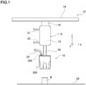
- FIG. 1 shows a configuration of an industrial robot 12 to which a gripping device 10 according to the embodiment is applied.
- the industrial robot 12 is an orthogonal robot and includes a rail 14, a moving body 16 that moves along the rail 14, and an air cylinder 18 secured to the moving body 16.
- the rail 14 is provided movably in a Y-axis direction in FIG. 1 .
- the air cylinder 18 includes a cylinder tube 19 and a piston rod 20 provided to be advanced from and retracted into the cylinder tube 19.
- the cylinder tube 19 includes pipes 21, 22. Air is supplied and exhausted through the pipes 21, 22 to allow the piston rod 20 to be advanced from and retracted into the cylinder tube 19.
- a gripping device 10 is provided at a distal end of the piston rod 20.
- the industrial robot 12 can grip a workpiece W placed on a horizontal base 26 with the gripping device 10 and move the workpiece W in X-axis, Y-axis, and Z-axis directions.
- the gripping device 10 includes a case 36A coupled to the piston rod 20 and a gripper 28A secured to the case 36A.
- a pipe 24 is coupled to the case 36A.
- the gripper 28A can be made of an airtight and elastic material, for example, natural rubber, synthetic rubber, or the like. Hardness of the gripper 28A measured according to JIS K6253: durometer hardness test (type A) is preferably about 60 to 90.
- the gripper 28A includes a palm portion 30 and a plurality of finger portions 32 provided to protrude from a periphery of the palm portion 30.
- the palm portion 30 has a substantially disk shape.
- Five finger portions 32 are radially provided and integrated with the palm portion 30 so as to surround the palm portion 30.
- a predetermined interval is formed between the finger portions 32.
- Inner surfaces of the finger portions 32 are integrated with the palm portion 30.
- Each of the finger portions 32 may have any outer shape, for example, a cylindrical shape, a conical shape, a truncated conical shape, a triangular prism shape, a square prism shape, a triangular pyramid shape, a square pyramid shape, a truncated square pyramid shape, a rectangular parallelepiped shape, or the like.
- the finger portions 32 have the same shape.
- the plurality of finger portions 32 need not all have the same shape but may have different shapes.
- Each of the finger portions 32 has a truncated square pyramid shape, and each of the inner surfaces is formed to be inclined outward from a base end continuous with the palm portion 30 toward a distal end.
- the gripper 28A includes integrally a connecting portion 38 in a position surrounding an outer edge of the palm portion 30 on a side opposite to a side formed with the finger portions 32.
- the connecting portion 38 has a cylindrical shape, and has a circular opening at an upper end in FIG. 3 .
- the finger portions 32 are solid.
- a material of the finger portions 32 may be the same as or different from a material of other portions (palm portion 30 or connecting portion 38). Further, the material of the finger portions 32 needs not be always uniform but may be a composite of different materials or may contain an additive such as a filler.
- the opening of the gripper 28A is sealed by the case 36A.
- the case 36A is preferably made of metal such as stainless, or rigid resin such as plastics, and includes a lower case 51 and an upper case 54.
- the lower case 51 includes a bottom 57 having a through hole 56 at a center, and a cylindrical portion 52 integrated with an outer edge of the bottom 57.
- An outer edge R of a bottom surface 55 as a distal end surface of the lower case 51 is chamfered.
- the outer edge of the bottom surface 55 may be cut into a corner surface or a rounded surface. Smaller chamfering is preferable to prevent local deformation of the connecting portion 38 in the thickness direction.
- the upper case 54 is a disk-like member, and has a joint 58 extending therethrough in the thickness direction.
- An end of the pipe 24 is connected to the joint 58 ( FIG. 3 ).
- the other end of the pipe 24 is connected to a vacuum pump, for example, via a three-way valve although not shown.
- the three-way valve includes a vacuum port, a supply and exhaust port, and an atmospheric release port.
- the vacuum port is connected to the vacuum pump, the supply and exhaust port is connected to the gripping device 10, and the atmospheric release port is connected to an outside.
- the lower case 51 and the upper case 54 are integrated via an O-ring 53 as a sealant at an upper end of the cylindrical portion 52. Between the bottom surface of the lower case 51 and an inner surface of the palm portion 30, a guide space 40 is formed that receives the palm portion 30 deformed in the thickness direction.
- the gripper 28A includes, between the connecting portion 38 and the palm portion 30, a high-strength portion 42 that is less likely to be deformed in the thickness direction than the palm portion 30.
- the high-strength portion 42 is integrated with the palm portion 30 and the connecting portion 38.
- the high-strength portion 42 includes a base end 44 coming into contact with the lower case 51, and a distal end 43 apart from the base end 44 toward the finger portions 32 and connected to the palm portion 30.
- the high-strength portion 42 is less likely to be deformed than the palm portion 30, but is not a complete rigid body.
- the high-strength portion 42 is microscopically deformed at the base end 44 as a fulcrum toward a center of the palm portion 30.
- the base end 44 is located apart from the outer edge of the palm portion 30 in the thickness direction of the palm portion 30, that is, in a position apart from the palm portion 30 toward the upper opening of the connecting portion 38.
- the base end 44 has a contact surface 45 coming into contact with an outer peripheral portion of the bottom surface 55 of the case 36A.
- the high-strength portion 42 has an inner peripheral surface 46 in contact with the guide space 40 on a center side of the palm portion 30 continuous with the contact surface 45.
- the palm portion 30 has, on its inner side, a substantially flat inner surface 48 and a curved surface 50 provided around the inner surface 48 and protruding outward.
- the inner peripheral surface 46 and the inner surface 48 of the palm portion 30 are connected by the curved surface 50.
- the distal end 43 of the high-strength portion 42 is located between the inner peripheral surface 46 and the curved surface 50.
- the distal end 43 serves as a fulcrum when the palm portion 30 is deformed in the thickness direction.
- the high-strength portion 42 is formed to surround the palm portion 30 according to the shape of the connecting portion 38.
- the high-strength portion 42 has an annular shape.
- the contact surface 45 is an upper surface of the high-strength portion 42.
- An entire outer peripheral portion of the bottom surface 55 of the case 36A comes into contact with the contact surface 45 of the high-strength portion 42.
- a slight part of the outer peripheral portion may not come into contact with the contact surface 45.
- the piston rod 20 is retracted in the cylinder tube 19, and the air cylinder 18 is contracted.
- pressure in the gripper 28A is atmospheric pressure in an initial state. Specifically, the three-way valve is in such a state that the vacuum port is blocked and the supply and exhaust port is connected to the atmospheric release port.
- the moving body 16 is moved along the rail 14 to position the gripping device 10 vertically above the workpiece W placed on the base 26 ( FIG. 1 ). Then, in the industrial robot 12, the piston rod 20 is advanced from the cylinder tube 19 to extend the air cylinder 18 until the finger portions 32 reach a side surface of the workpiece W.
- the three-way valve is switched to a state where the atmospheric release port is blocked and the supply and exhaust port is connected to the vacuum port.
- the gripping device 10 sucks air in the gripper 28A through the pipe 24, and reduces the pressure in the gripper 28A to -0.03 MPa or lower.
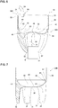
- the high-strength portion 42 of the gripper 28A keeps holding the shape. Then, the palm portion 30 is deformed in the thickness direction so as to be sucked into the guide space 40 ( FIG. 6 ). As the palm portion 30 is deformed in the thickness direction, the inner surfaces of the finger portions 32 are pulled toward the center of the palm portion 30. Then, the finger portions 32 are elastically deformed to fall toward the palm portion 30. Thus, the finger portions 32, mainly, the inner surfaces 31 come into contact with surfaces of the workpiece W.
- the high-strength portion 42 is microscopically elastically deformed at the base end 44 as a fulcrum according to the deformation of the palm portion 30.
- the finger portions 32 come into contact with the side surfaces of the workpiece W.
- the gripping device 10 reduces the pressure in the gripper 28A to grip the workpiece W.
- the gripping device 10 exerts a gripping force according to the pressure in the gripper 28A. Specifically, the gripping force of the gripping device 10 increases with decreasing pressure in the gripper 28A.
- the piston rod 20 is retracted into the cylinder tube 19 to contract the air cylinder 18, thereby allowing the workpiece W to be lifted from the base 26.
- the moving body 16 is moved along the rail 14 or the rail 14 is moved in the Y-axis direction, thereby allowing the workpiece W to be freely moved in a horizontal direction.
- the piston rod 20 is advanced from the cylinder tube 19 to extend the air cylinder 18 until the workpiece W comes into contact with the base 26. Then, the three-way valve is switched to the state where the vacuum port is blocked and the supply and exhaust port is connected to the atmospheric release port. Then, air flows from the atmospheric release port through the pipe 24 into the gripper 28A. As the pressure in the gripper 28A returns to atmospheric pressure, the palm portion 30 is pressed out of the guide space and returns to its original state. As the palm portion 30 returns to its original state, the finger portions 32 are opened to release the workpiece W.
- the piston rod 20 is retracted into the cylinder tube 19 to contract the air cylinder 18 to separate the gripping device 10 from the workpiece W.
- the industrial robot 12 can grip the workpiece W placed on the base 26 with the gripping device 10 to move the workpiece W to a desired position.
- the high-strength portion 42 prevents contraction of an outer periphery of the palm portion 30, and thus the palm portion 30 is deformed in the thickness direction to deform the finger portions 32 toward the palm portion 30.
- the gripping device 10 can more reliably grip the workpiece W without using a granular material. Since the gripping device 10 does not use a granular material, the workpiece W is not contaminated even if the gripper 28A bursts.
- the gripper 28A does not use a granular material, and thus can grip the workpiece W even if the distal ends of the finger portions 32 are directed downward, sideways, or upward.
- the gripping device 10 can lift the workpiece W on the base 26 and also can grip the workpiece W suspended from a vertical wall surface or a ceiling.
- the finger portions 32 have higher rigidity than a granular material after jamming transition, thereby allowing the workpiece W to be more reliably gripped.
- the gripping device 10 reduces the pressure in the gripper 28A to reliably deform the palm portion 30 in the thickness direction, thereby gripping the workpiece W. Thus, there is no need to press the gripper 28A against the workpiece W. Thus, the gripping device 10 can grip a soft workpiece W such as food without crushing the workpiece W, thereby preventing damage to the workpiece W.
- the gripper 28A can change an amount of deformation of the finger portions 32 and a gripping force according to a degree of reduction in pressure in the gripper 28A.
- the gripping device 10 can change the gripping force according to a size or hardness of the workpiece W, thereby improving versatility.
- the palm portion 30 is deformed in the thickness direction so as to be sucked into the guide space 40, and thus the finger portions 32 are deformed at a sharper angle toward the palm portion 30. This allows the gripping device 10 to grip a smaller workpiece W.
- the high-strength portion 42 is integrated with the palm portion 30 and the finger portions 32, and is microscopically deformed according to the deformation of the palm portion 30 in the thickness direction.
- the finger portions 32 are continuously and gently deformed according to the deformation of the palm portion 30.
- the gripping device 10 can softly grip the workpiece W.
- finger portions 32 are deformed to be buckled.
- the gripper 28A includes integrally the palm portion 30, the finger portions 32, the high-strength portion 42, and the connecting portion 38, thereby reducing the number of components and the number of manufacturing steps.
- the palm portion 30, to which a heavy load is applied when the pressure is reduced, and the high-strength portion 42 are integrated, thereby preventing damage to the gripper 28A and improving durability.
- a gripper 28B in FIG. 7 is different from the gripper of the embodiment in that a curved surface protruding outward is provided between a contact surface 62 of a high-strength portion 60 and an inner surface of the connecting portion 38.
- Providing the curved surface protruding outward between the contact surface 62 and the inner surface of the connecting portion 38 increases mechanical strength of the connecting portion 38 in a position corresponding to the distal end of the case 36A, thereby preventing local deformation of the connecting portion 38 in the thickness direction.
- Preventing the local deformation of the connecting portion 38 allows uniform deformation of the finger portions 32, and thus the gripper 28B can more reliably grip the workpiece W.
- the local deformation of the connecting portion 38 in the position corresponding to the distal end of the case 36A causes deviation of the gripper from the case 36A when the pressure is reduced, which makes it difficult for the finger portions 32 to be uniformly deformed.
- a high-strength portion 69 of a gripper 28C in FIGS. 8 and 9 includes a plurality of strips 64 provided in positions corresponding to the finger portions 32.
- the number of the strips 64 is five like the finger portions 32.
- the strips 64 are arranged at regular intervals at base ends of the finger portions 32 around the palm portion 30.
- Each of the strips 64 has a contact surface 63 as an upper surface and an inner peripheral surface 65 as an inner surface on a side of the palm portion 30.
- a distal end 49 of the high-strength portion 69 is located between the inner peripheral surface 65 and the curved surface 50. The distal end 49 serves as a fulcrum when the palm portion 30 is deformed in the thickness direction.
- the outer peripheral portion of the bottom surface 55 of the case 36A partially comes into contact with the contact surface 63 of the high-strength portion 69.
- the gripper 28C in FIGS. 8 and 9 includes the high-strength portion 69, and thus may have the same advantage as in the embodiment.
- the high-strength portion 69 in this modified example can reduce an amount of material between the strips 64 as compared to an annular high-strength portion, thereby reducing weight.
- a high-strength portion 66 of a gripper 28D in FIGS. 10A and 10B includes a plurality of annular protrusions 67.
- the annular protrusions 67 are arranged at predetermined intervals in parallel with the thickness direction of the palm portion 30.
- An upper surface of one of the protrusions 67 located farthest from the palm portion 30 is a contact surface 68.
- An inner surface of each of the protrusions 67 on the side of the palm portion 30 is an inner peripheral surface 70.
- a flat surface is formed between the inner peripheral surface 70 and the inner surface 48 of the palm portion 30.
- the entire outer peripheral portion of the bottom surface 55 of the case 36A comes into contact with the contact surface 68 of the high-strength portion 66.
- the gripper 28D in FIGS. 10A and 10B includes the high-strength portion 66, and thus may have the same advantage as in the embodiment.
- a high-strength portion 74 of a gripper 28E in FIGS. 11A and 11B includes a plurality of ribs 79 whose longitudinal direction is the thickness direction of the palm portion 30.
- the ribs 79 are arranged at predetermined intervals around the palm portion 30.
- An upper surface of each of the ribs 79 is a contact surface 76
- an inner surface of each of the ribs 79 on the side of the palm portion 30 is an inner peripheral surface 78.
- a flat surface is formed between the inner peripheral surface 78 and the inner surface 48 of the palm portion 30.
- the outer peripheral portion of the bottom surface 55 of the case 36A partially comes into contact with the contact surface 76 of the high-strength portion 74.
- the gripper 28E in FIGS. 11A and 11B includes the high-strength portion 74, and thus may have the same advantage as in the embodiment.
- a high-strength portion 82 of a gripper 28F in FIG. 12 is made of a material having higher mechanical strength than a material of the palm portion 30.
- a base end of the high-strength portion 82 is a portion 84 coming into contact with the distal end of the case 36A.
- a distal end 86 of the high-strength portion 82 as an interface with the palm portion 30 serves as a fulcrum when the palm portion 30 is deformed in the thickness direction.
- An inner peripheral surface 87 of the high-strength portion 82 on the side of the palm portion 30 is gently continuous with the curved surface 50.
- the gripper 28F in FIG. 12 can be manufactured by insert molding as shown in FIG. 13 .
- a mold is used constituted by a lower mold 88 having a recess 91 in the shape of each finger portion 32, and an upper mold 89 having a protrusion in the shape of the guide space 40.
- the high-strength portion 82 which is previously made of a predetermined material, for example, a resin material having higher hardness than a material for making the palm portion 30 and the finger portions 32, is placed in a predetermined position, and the upper mold 89 is fitted to the lower mold 88.
- a resin material for making the palm portion 30 and the finger portions 32 is charged into a space surrounded by the lower mold 88 and the upper mold 89.
- the mold is removed to obtain the gripper 28F including integrally the high-strength portion 82, the finger portions 32, and the palm portion 30.
- the gripper 28F in FIG. 12 includes the high-strength portion 82, and thus may have the same advantage as in the embodiment.
- a lower case 51 having the bottom 57 has been described, but the present invention is not limited to this.
- a lower case 51 has a cylindrical shape without a bottom.
- a lower end 61 as a distal end of the lower case 51 comes into contact with the base end of the high-strength portion 42.
- a case 36C in FIG. 15 includes a disk-like upper case 93 and an annular lower case 95.
- a gripper 28G includes a flange-like connecting portion 94 integrated with a peripheral edge of an opening. The connecting portion 94 is held and fixed between the upper case 93 and the lower case 95 to seal the opening of the gripper 28G.
- a high-strength portion 92 of the gripper 28G is thicker than the palm portion 30, and is less likely to be deformed in the thickness direction than the palm portion 30.
- a base end 96 of the high-strength portion 92 comes into contact with a lower surface of the upper case 93.
- the gripper 28G in FIG. 15 includes the high-strength portion 92, and thus may have the same advantage as in the embodiment.
- the palm portion 30 having the substantially disk shape, the connecting portion 38 having the cylindrical shape, and the upper opening of the gripper 28A having the circular shape have been described, but the present invention is not limited to them.
- the palm portion 30, the connecting portion 38, and the upper opening may each have an elliptical shape, an oval shape, or a rectangular shape in a plan view.
- two sets of finger portions 32 (each set including, for example, two finger portions) along long sides of the palm portion 30 may be provided on opposite sides of the palm portion 30.
- a gripping device including such a gripper can easily grip a long member such as of a cylindrical shape or a prism shape.
- the orthogonal robot is exemplified as the industrial robot 12.
- the present invention is not limited to this, but may be applied to a SCARA robot, an articulated robot, or the like.
- the gripping device 10 can grip the workpiece W and keep the gripping state even if rotated around X, Y, and Z axes by the industrial robot 12.
- the gripper 28A may be made of one material or may be formed of a stack of films of a plurality of different materials.
- the gripper 28A may be partially made of a different material.
- the gripper 28A needs not have a fixed thickness, but may partially have a thick or thin portion.
- the gripping device 10 may have a claw portion on the finger portion 32.
- the claw portion may be made of a plate-like member, a conical member, or a sack-like member of synthetic resin.
- the gripping device 10 may include a camera for taking an image of the workpiece W, a gravimeter for measuring a weight of the gripped workpiece W, a proximity sensor for measuring a distance between the workpiece W and the gripper 28A, or the like.
- An appearance configuration of the gripper 28A is not limited to one shown in FIG. 2 .
- a length of each finger portion 32 and the number of finger portions 32 may be selected as appropriate.
Landscapes
- Engineering & Computer Science (AREA)
- Robotics (AREA)
- Mechanical Engineering (AREA)
- Manipulator (AREA)
- Load-Engaging Elements For Cranes (AREA)
Abstract
Description
- The present invention relates to a gripper, a gripping device, and an industrial robot.
- As a gripping device for gripping a workpiece, a gripping device is disclosed that includes a bag-shaped gripping body including a palm portion, a plurality of finger portions protruding from a periphery of the palm portion and configured to fall toward the palm portion by deforming the palm portion in a thickness direction, and a granular material held in the gripping body (Patent Literature 1). The gripping device reduces pressure in the gripping body to deform the palm portion in the thickness direction and elastically deform the finger portions to fall toward the palm portion. Since including the plurality of finger portions, the gripping device can versatilely grip workpieces of different sizes or shapes. The gripping device can grip a workpiece merely by reducing pressure in the gripping body and thus can be simply controlled. Also, there is no need to press the gripping body hard against a workpiece, and thus a soft workpiece such as food can be gripped without being damaged.
- Patent Literature 1: Japanese Patent Laid-Open No.
2017-185553 - However, if the gripping body of the gripping device in Patent Literature 1 bursts due to deterioration, breakage, or the like, the granular material filling the gripping body scatters and contaminates the workpiece. This is a problem. The granular material is deteriorated by density changes due to jamming transition, and cannot be stably used. This is a problem.
- An object of the present invention is to provide a gripper, a gripping device, and an industrial robot that can more reliably grip a workpiece without using a granular material.
- A gripper according to the present invention includes integrally: a palm portion; a plurality of finger portions protruding from a periphery of the palm portion and configured to fall toward the palm portion by deforming the palm portion in a thickness direction; a connecting portion formed in a position surrounding an outer edge of the palm portion on a side opposite to a side formed with the finger portions, the connecting portion connected to a case; and a high-strength portion provided between the palm portion and the connecting portion, the high-strength portion having a predetermined length from the outer edge of the palm portion in the thickness direction of the palm portion, and the high-strength portion being less likely to be deformed than the palm portion.
- A gripping device according to the present invention includes: the gripper, and the case connected to the connecting portion.
- An industrial robot according to the present invention includes the gripping device.
- According to the present invention, the high-strength portion prevents contraction of an outer periphery of the palm portion, and thus the palm portion is deformed in the thickness direction to deform the finger portions toward the palm portion, thereby gripping a workpiece. Thus, the workpiece can be more reliably gripped without using a granular material. The high-strength portion is integrated with the palm portion and the finger portions, and thus the finger portions are continuously and gently deformed. Thus, the gripping device can softly grip the workpiece.
-
-
FIG. 1 is a schematic view of an example of an industrial robot to which a gripping device according to the embodiment is applied; -
FIG. 2 is a perspective view of a configuration of the gripping device according to the embodiment; -
FIG. 3 is a vertical sectional view of the configuration of the gripping device according to the embodiment; -
FIG. 4 is a vertical sectional view of a configuration of a case according to the embodiment; -
FIG. 5 is a perspective view of a configuration of a gripper according to the embodiment; -
FIG. 6 is a vertical sectional view of a use state of the gripping device according to the embodiment; -
FIG. 7 is a vertical sectional view of a configuration of a gripper according to Modified example (1) ; -
FIG. 8 is a vertical sectional view of a configuration of a gripper according to Modified example (2) ; -
FIG. 9 is a perspective view of the configuration of the gripper according to Modified example (2); - Each of
FIGs. 10A and 10B shows a gripper according to Modified example (3),FIG. 10A is a partial end view, andFIG. 10B is a perspective view; - Each of
FIGs. 11A and 11B shows a gripper according to Modified example (4),FIG. 11A is a vertical sectional view, andFIG. 11B is a perspective view; -
FIG. 12 is a partial vertical sectional view of a gripper according to Modified example (5); -
FIG. 13 is a partial vertical sectional view illustrating a method for manufacturing the gripper according to Modified example (5); -
FIG. 14 is a vertical sectional view of a configuration of a case according to a modified example; and -
FIG. 15 is a partial vertical sectional view of a configuration of a gripping device according to a modified example. - A gripper according to the present invention includes integrally: a palm portion; a plurality of finger portions protruding from a periphery of the palm portion and configured to fall toward the palm portion by deforming the palm portion in a thickness direction; a connecting portion formed in a position surrounding an outer edge of the palm portion on a side opposite to a side formed with the finger portions, the connecting portion connected to a case; and a high-strength portion provided between the palm portion and the connecting portion, the high-strength portion having a predetermined length from the outer edge of the palm portion in the thickness direction of the palm portion, and the high-strength portion being less likely to be deformed than the palm portion.
- The high-strength portion is less likely to be deformed than the palm portion, and thus when pressure in the palm portion is reduced, the palm portion is deformed in the thickness direction without its outer periphery contracting. Thus, the finger portions of the gripper are elastically deformed to fall toward the palm portion, and thus the gripper can more reliably grip the workpiece without using a granular material.
- The high-strength portion is a certain region between the connecting portion and the palm portion. The high-strength portion is formed to have higher mechanical strength than the palm portion. The high-strength portion may be uniformly or partially provided around the palm portion. Specifically, the high-strength portion may be thicker than the palm portion. In this case, the high-strength portion may be uniformly or partially thick. When being partially thick, the high-strength portion may be partially thick in a circumferential direction of the palm portion or in a direction parallel to the thickness direction of the palm portion. The high-strength portion may be made of a material having higher mechanical strength than a material of the palm portion. The material having high mechanical strength may include a material of the same nature as the material of the palm portion but having higher hardness, a material different from the material of the palm portion, a material containing an additive such as a filler, or a composite thereof.
- A base end of the high-strength portion comes into contact with a part of the case. The base end of the high-strength portion may come into surface contact or line contact with the case. The base end preferably has a contact surface coming into contact with the case. When the case includes an upper case and a lower case, the upper case may come into contact with the contact surface or the lower case may come into contact with the contact surface.
- The high-strength portion is a certain region from the base end to a distal end connected to the palm portion. The distal end is a boundary between the high-strength portion and the palm portion, but cannot be always clearly visually recognized. The distal end preferably serves as a fulcrum when the palm portion is deformed in the thickness direction.
- Now, with reference to drawings, embodiments of the present invention will be described in detail.
-
FIG. 1 shows a configuration of anindustrial robot 12 to which agripping device 10 according to the embodiment is applied. Theindustrial robot 12 is an orthogonal robot and includes arail 14, a movingbody 16 that moves along therail 14, and anair cylinder 18 secured to the movingbody 16. Therail 14 is provided movably in a Y-axis direction inFIG. 1 . - The
air cylinder 18 includes acylinder tube 19 and apiston rod 20 provided to be advanced from and retracted into thecylinder tube 19. Thecylinder tube 19 includespipes pipes piston rod 20 to be advanced from and retracted into thecylinder tube 19. Agripping device 10 is provided at a distal end of thepiston rod 20. - The
industrial robot 12 can grip a workpiece W placed on ahorizontal base 26 with thegripping device 10 and move the workpiece W in X-axis, Y-axis, and Z-axis directions. - The
gripping device 10 includes acase 36A coupled to thepiston rod 20 and agripper 28A secured to thecase 36A. Apipe 24 is coupled to thecase 36A. Thegripper 28A can be made of an airtight and elastic material, for example, natural rubber, synthetic rubber, or the like. Hardness of thegripper 28A measured according to JIS K6253: durometer hardness test (type A) is preferably about 60 to 90. - As shown in
FIG. 2 , thegripper 28A includes apalm portion 30 and a plurality offinger portions 32 provided to protrude from a periphery of thepalm portion 30. Thepalm portion 30 has a substantially disk shape. Fivefinger portions 32 are radially provided and integrated with thepalm portion 30 so as to surround thepalm portion 30. A predetermined interval is formed between thefinger portions 32. Inner surfaces of thefinger portions 32 are integrated with thepalm portion 30. Each of thefinger portions 32 may have any outer shape, for example, a cylindrical shape, a conical shape, a truncated conical shape, a triangular prism shape, a square prism shape, a triangular pyramid shape, a square pyramid shape, a truncated square pyramid shape, a rectangular parallelepiped shape, or the like. In the embodiment, thefinger portions 32 have the same shape. The plurality offinger portions 32 need not all have the same shape but may have different shapes. Each of thefinger portions 32 has a truncated square pyramid shape, and each of the inner surfaces is formed to be inclined outward from a base end continuous with thepalm portion 30 toward a distal end. - As shown in
FIG. 3 , thegripper 28A includes integrally a connectingportion 38 in a position surrounding an outer edge of thepalm portion 30 on a side opposite to a side formed with thefinger portions 32. The connectingportion 38 has a cylindrical shape, and has a circular opening at an upper end inFIG. 3 . Thefinger portions 32 are solid. A material of thefinger portions 32 may be the same as or different from a material of other portions (palm portion 30 or connecting portion 38). Further, the material of thefinger portions 32 needs not be always uniform but may be a composite of different materials or may contain an additive such as a filler. The opening of thegripper 28A is sealed by thecase 36A. - As shown in
FIG. 4 , thecase 36A is preferably made of metal such as stainless, or rigid resin such as plastics, and includes alower case 51 and anupper case 54. Thelower case 51 includes a bottom 57 having a throughhole 56 at a center, and acylindrical portion 52 integrated with an outer edge of the bottom 57. An outer edge R of abottom surface 55 as a distal end surface of thelower case 51 is chamfered. For chamfering, the outer edge of thebottom surface 55 may be cut into a corner surface or a rounded surface. Smaller chamfering is preferable to prevent local deformation of the connectingportion 38 in the thickness direction. - The
upper case 54 is a disk-like member, and has a joint 58 extending therethrough in the thickness direction. An end of thepipe 24 is connected to the joint 58 (FIG. 3 ). The other end of thepipe 24 is connected to a vacuum pump, for example, via a three-way valve although not shown. The three-way valve includes a vacuum port, a supply and exhaust port, and an atmospheric release port. The vacuum port is connected to the vacuum pump, the supply and exhaust port is connected to thegripping device 10, and the atmospheric release port is connected to an outside. Through thepipe 24, air flows from inside to outside thegripper 28A and from outside to inside thegripper 28A. - The
lower case 51 and theupper case 54 are integrated via an O-ring 53 as a sealant at an upper end of thecylindrical portion 52. Between the bottom surface of thelower case 51 and an inner surface of thepalm portion 30, aguide space 40 is formed that receives thepalm portion 30 deformed in the thickness direction. - The
gripper 28A includes, between the connectingportion 38 and thepalm portion 30, a high-strength portion 42 that is less likely to be deformed in the thickness direction than thepalm portion 30. The high-strength portion 42 is integrated with thepalm portion 30 and the connectingportion 38. The high-strength portion 42 includes abase end 44 coming into contact with thelower case 51, and adistal end 43 apart from thebase end 44 toward thefinger portions 32 and connected to thepalm portion 30. The high-strength portion 42 is less likely to be deformed than thepalm portion 30, but is not a complete rigid body. The high-strength portion 42 is microscopically deformed at thebase end 44 as a fulcrum toward a center of thepalm portion 30. - The
base end 44 is located apart from the outer edge of thepalm portion 30 in the thickness direction of thepalm portion 30, that is, in a position apart from thepalm portion 30 toward the upper opening of the connectingportion 38. In the embodiment, thebase end 44 has acontact surface 45 coming into contact with an outer peripheral portion of thebottom surface 55 of thecase 36A. The high-strength portion 42 has an innerperipheral surface 46 in contact with theguide space 40 on a center side of thepalm portion 30 continuous with thecontact surface 45. Thepalm portion 30 has, on its inner side, a substantially flatinner surface 48 and acurved surface 50 provided around theinner surface 48 and protruding outward. The innerperipheral surface 46 and theinner surface 48 of thepalm portion 30 are connected by thecurved surface 50. - The
distal end 43 of the high-strength portion 42 is located between the innerperipheral surface 46 and thecurved surface 50. Thedistal end 43 serves as a fulcrum when thepalm portion 30 is deformed in the thickness direction. - As shown in
FIG. 5 , the high-strength portion 42 is formed to surround thepalm portion 30 according to the shape of the connectingportion 38. InFIG. 5 , the high-strength portion 42 has an annular shape. Thecontact surface 45 is an upper surface of the high-strength portion 42. An entire outer peripheral portion of thebottom surface 55 of thecase 36A comes into contact with thecontact surface 45 of the high-strength portion 42. Although the entire outer peripheral portion is mentioned, a slight part of the outer peripheral portion may not come into contact with thecontact surface 45. - Operation and effect of the
industrial robot 12 including thegripping device 10 configured as described above will be described. At a starting point of theindustrial robot 12, thepiston rod 20 is retracted in thecylinder tube 19, and theair cylinder 18 is contracted. In thegripping device 10, pressure in thegripper 28A is atmospheric pressure in an initial state. Specifically, the three-way valve is in such a state that the vacuum port is blocked and the supply and exhaust port is connected to the atmospheric release port. - In the
industrial robot 12, the movingbody 16 is moved along therail 14 to position thegripping device 10 vertically above the workpiece W placed on the base 26 (FIG. 1 ). Then, in theindustrial robot 12, thepiston rod 20 is advanced from thecylinder tube 19 to extend theair cylinder 18 until thefinger portions 32 reach a side surface of the workpiece W. - Then, the three-way valve is switched to a state where the atmospheric release port is blocked and the supply and exhaust port is connected to the vacuum port. Thus, the gripping
device 10 sucks air in thegripper 28A through thepipe 24, and reduces the pressure in thegripper 28A to -0.03 MPa or lower. - The high-
strength portion 42 of thegripper 28A keeps holding the shape. Then, thepalm portion 30 is deformed in the thickness direction so as to be sucked into the guide space 40 (FIG. 6 ). As thepalm portion 30 is deformed in the thickness direction, the inner surfaces of thefinger portions 32 are pulled toward the center of thepalm portion 30. Then, thefinger portions 32 are elastically deformed to fall toward thepalm portion 30. Thus, thefinger portions 32, mainly, theinner surfaces 31 come into contact with surfaces of the workpiece W. The high-strength portion 42 is microscopically elastically deformed at thebase end 44 as a fulcrum according to the deformation of thepalm portion 30. - For the cubic workpiece W in
FIG. 6 , thefinger portions 32 come into contact with the side surfaces of the workpiece W. As described above, the grippingdevice 10 reduces the pressure in thegripper 28A to grip the workpiece W. Thegripping device 10 exerts a gripping force according to the pressure in thegripper 28A. Specifically, the gripping force of thegripping device 10 increases with decreasing pressure in thegripper 28A. - Then, in the
industrial robot 12, thepiston rod 20 is retracted into thecylinder tube 19 to contract theair cylinder 18, thereby allowing the workpiece W to be lifted from thebase 26. Further, in theindustrial robot 12, the movingbody 16 is moved along therail 14 or therail 14 is moved in the Y-axis direction, thereby allowing the workpiece W to be freely moved in a horizontal direction. - After the workpiece W is moved to a desired position, in the
industrial robot 12, thepiston rod 20 is advanced from thecylinder tube 19 to extend theair cylinder 18 until the workpiece W comes into contact with thebase 26. Then, the three-way valve is switched to the state where the vacuum port is blocked and the supply and exhaust port is connected to the atmospheric release port. Then, air flows from the atmospheric release port through thepipe 24 into thegripper 28A. As the pressure in thegripper 28A returns to atmospheric pressure, thepalm portion 30 is pressed out of the guide space and returns to its original state. As thepalm portion 30 returns to its original state, thefinger portions 32 are opened to release the workpiece W. - Then, in the
industrial robot 12, thepiston rod 20 is retracted into thecylinder tube 19 to contract theair cylinder 18 to separate thegripping device 10 from the workpiece W. In this manner, theindustrial robot 12 can grip the workpiece W placed on the base 26 with thegripping device 10 to move the workpiece W to a desired position. - The high-
strength portion 42 prevents contraction of an outer periphery of thepalm portion 30, and thus thepalm portion 30 is deformed in the thickness direction to deform thefinger portions 32 toward thepalm portion 30. Thus, the grippingdevice 10 can more reliably grip the workpiece W without using a granular material. Since thegripping device 10 does not use a granular material, the workpiece W is not contaminated even if thegripper 28A bursts. - The
gripper 28A does not use a granular material, and thus can grip the workpiece W even if the distal ends of thefinger portions 32 are directed downward, sideways, or upward. Thus, the grippingdevice 10 can lift the workpiece W on thebase 26 and also can grip the workpiece W suspended from a vertical wall surface or a ceiling. Thefinger portions 32 have higher rigidity than a granular material after jamming transition, thereby allowing the workpiece W to be more reliably gripped. - The
gripping device 10 reduces the pressure in thegripper 28A to reliably deform thepalm portion 30 in the thickness direction, thereby gripping the workpiece W. Thus, there is no need to press thegripper 28A against the workpiece W. Thus, the grippingdevice 10 can grip a soft workpiece W such as food without crushing the workpiece W, thereby preventing damage to the workpiece W. - The
gripper 28A can change an amount of deformation of thefinger portions 32 and a gripping force according to a degree of reduction in pressure in thegripper 28A. Thus, the grippingdevice 10 can change the gripping force according to a size or hardness of the workpiece W, thereby improving versatility. Thepalm portion 30 is deformed in the thickness direction so as to be sucked into theguide space 40, and thus thefinger portions 32 are deformed at a sharper angle toward thepalm portion 30. This allows thegripping device 10 to grip a smaller workpiece W. - The high-
strength portion 42 is integrated with thepalm portion 30 and thefinger portions 32, and is microscopically deformed according to the deformation of thepalm portion 30 in the thickness direction. Thus, thefinger portions 32 are continuously and gently deformed according to the deformation of thepalm portion 30. Thus, the grippingdevice 10 can softly grip the workpiece W. In agripper 28A without a high-strength portion 42,finger portions 32 are deformed to be buckled. - The
gripper 28A includes integrally thepalm portion 30, thefinger portions 32, the high-strength portion 42, and the connectingportion 38, thereby reducing the number of components and the number of manufacturing steps. Thepalm portion 30, to which a heavy load is applied when the pressure is reduced, and the high-strength portion 42 are integrated, thereby preventing damage to thegripper 28A and improving durability. - The present invention is not limited to the above embodiment, but may be changed as appropriate within the scope of the present invention.
- For example, a
gripper 28B inFIG. 7 is different from the gripper of the embodiment in that a curved surface protruding outward is provided between acontact surface 62 of a high-strength portion 60 and an inner surface of the connectingportion 38. Providing the curved surface protruding outward between thecontact surface 62 and the inner surface of the connectingportion 38 increases mechanical strength of the connectingportion 38 in a position corresponding to the distal end of thecase 36A, thereby preventing local deformation of the connectingportion 38 in the thickness direction. Preventing the local deformation of the connectingportion 38 allows uniform deformation of thefinger portions 32, and thus thegripper 28B can more reliably grip the workpiece W. The local deformation of the connectingportion 38 in the position corresponding to the distal end of thecase 36A causes deviation of the gripper from thecase 36A when the pressure is reduced, which makes it difficult for thefinger portions 32 to be uniformly deformed. - A high-
strength portion 69 of a gripper 28C inFIGS. 8 and 9 includes a plurality ofstrips 64 provided in positions corresponding to thefinger portions 32. InFIGS. 8 and 9 , the number of thestrips 64 is five like thefinger portions 32. Thestrips 64 are arranged at regular intervals at base ends of thefinger portions 32 around thepalm portion 30. Each of thestrips 64 has acontact surface 63 as an upper surface and an innerperipheral surface 65 as an inner surface on a side of thepalm portion 30. Adistal end 49 of the high-strength portion 69 is located between the innerperipheral surface 65 and thecurved surface 50. Thedistal end 49 serves as a fulcrum when thepalm portion 30 is deformed in the thickness direction. The outer peripheral portion of thebottom surface 55 of thecase 36A partially comes into contact with thecontact surface 63 of the high-strength portion 69. The gripper 28C inFIGS. 8 and 9 includes the high-strength portion 69, and thus may have the same advantage as in the embodiment. The high-strength portion 69 in this modified example can reduce an amount of material between thestrips 64 as compared to an annular high-strength portion, thereby reducing weight. - A high-
strength portion 66 of agripper 28D inFIGS. 10A and 10B includes a plurality ofannular protrusions 67. Theannular protrusions 67 are arranged at predetermined intervals in parallel with the thickness direction of thepalm portion 30. An upper surface of one of theprotrusions 67 located farthest from thepalm portion 30 is acontact surface 68. An inner surface of each of theprotrusions 67 on the side of thepalm portion 30 is an innerperipheral surface 70. A flat surface is formed between the innerperipheral surface 70 and theinner surface 48 of thepalm portion 30. The entire outer peripheral portion of thebottom surface 55 of thecase 36A comes into contact with thecontact surface 68 of the high-strength portion 66. Thegripper 28D inFIGS. 10A and 10B includes the high-strength portion 66, and thus may have the same advantage as in the embodiment. - A high-
strength portion 74 of agripper 28E inFIGS. 11A and 11B includes a plurality ofribs 79 whose longitudinal direction is the thickness direction of thepalm portion 30. Theribs 79 are arranged at predetermined intervals around thepalm portion 30. An upper surface of each of theribs 79 is acontact surface 76, and an inner surface of each of theribs 79 on the side of thepalm portion 30 is an innerperipheral surface 78. A flat surface is formed between the innerperipheral surface 78 and theinner surface 48 of thepalm portion 30. The outer peripheral portion of thebottom surface 55 of thecase 36A partially comes into contact with thecontact surface 76 of the high-strength portion 74. Thegripper 28E inFIGS. 11A and 11B includes the high-strength portion 74, and thus may have the same advantage as in the embodiment. - A high-
strength portion 82 of agripper 28F inFIG. 12 is made of a material having higher mechanical strength than a material of thepalm portion 30. InFIG. 12 , a base end of the high-strength portion 82 is aportion 84 coming into contact with the distal end of thecase 36A. Adistal end 86 of the high-strength portion 82 as an interface with thepalm portion 30 serves as a fulcrum when thepalm portion 30 is deformed in the thickness direction. An innerperipheral surface 87 of the high-strength portion 82 on the side of thepalm portion 30 is gently continuous with thecurved surface 50. Thegripper 28F inFIG. 12 can be manufactured by insert molding as shown inFIG. 13 . To manufacture thegripper 28F, a mold is used constituted by alower mold 88 having arecess 91 in the shape of eachfinger portion 32, and anupper mold 89 having a protrusion in the shape of theguide space 40. The high-strength portion 82, which is previously made of a predetermined material, for example, a resin material having higher hardness than a material for making thepalm portion 30 and thefinger portions 32, is placed in a predetermined position, and theupper mold 89 is fitted to thelower mold 88. Through aninjection hole 90 provided in theupper mold 89, a resin material for making thepalm portion 30 and thefinger portions 32 is charged into a space surrounded by thelower mold 88 and theupper mold 89. When the resin hardens, the mold is removed to obtain thegripper 28F including integrally the high-strength portion 82, thefinger portions 32, and thepalm portion 30. Thegripper 28F inFIG. 12 includes the high-strength portion 82, and thus may have the same advantage as in the embodiment. - In the embodiment, the
lower case 51 having the bottom 57 has been described, but the present invention is not limited to this. For example, in acase 36B inFIG. 14 , alower case 51 has a cylindrical shape without a bottom. Alower end 61 as a distal end of thelower case 51 comes into contact with the base end of the high-strength portion 42. - A
case 36C inFIG. 15 includes a disk-likeupper case 93 and an annularlower case 95. Agripper 28G includes a flange-like connectingportion 94 integrated with a peripheral edge of an opening. The connectingportion 94 is held and fixed between theupper case 93 and thelower case 95 to seal the opening of thegripper 28G. A high-strength portion 92 of thegripper 28G is thicker than thepalm portion 30, and is less likely to be deformed in the thickness direction than thepalm portion 30. Abase end 96 of the high-strength portion 92 comes into contact with a lower surface of theupper case 93. Thegripper 28G inFIG. 15 includes the high-strength portion 92, and thus may have the same advantage as in the embodiment. - In the embodiment, the
palm portion 30 having the substantially disk shape, the connectingportion 38 having the cylindrical shape, and the upper opening of thegripper 28A having the circular shape have been described, but the present invention is not limited to them. Thepalm portion 30, the connectingportion 38, and the upper opening may each have an elliptical shape, an oval shape, or a rectangular shape in a plan view. For example, when these potions each have a rectangular shape, two sets of finger portions 32 (each set including, for example, two finger portions) along long sides of thepalm portion 30 may be provided on opposite sides of thepalm portion 30. A gripping device including such a gripper can easily grip a long member such as of a cylindrical shape or a prism shape. - In the embodiment, the orthogonal robot is exemplified as the
industrial robot 12. However, the present invention is not limited to this, but may be applied to a SCARA robot, an articulated robot, or the like. Specifically, the grippingdevice 10 can grip the workpiece W and keep the gripping state even if rotated around X, Y, and Z axes by theindustrial robot 12. - The
gripper 28A may be made of one material or may be formed of a stack of films of a plurality of different materials. Thegripper 28A may be partially made of a different material. Thegripper 28A needs not have a fixed thickness, but may partially have a thick or thin portion. - The
gripping device 10 may have a claw portion on thefinger portion 32. The claw portion may be made of a plate-like member, a conical member, or a sack-like member of synthetic resin. - The
gripping device 10 may include a camera for taking an image of the workpiece W, a gravimeter for measuring a weight of the gripped workpiece W, a proximity sensor for measuring a distance between the workpiece W and thegripper 28A, or the like. - An appearance configuration of the
gripper 28A is not limited to one shown inFIG. 2 . For example, a length of eachfinger portion 32 and the number offinger portions 32 may be selected as appropriate. -
- 10
- gripping device
- 12
- industrial robot
- 28A to 28G
- gripper
- 30
- palm portion
- 32
- finger portion
- 36A to 36C
- case
- 42, 60, 66, 69, 74, 82, 92
- high-strength portion
- 43
- distal end
- 44
- base end
- 45, 62, 63, 68, 76
- contact surface
Claims (7)
- A gripper comprising integrally:a palm portion;a plurality of finger portions protruding from a periphery of the palm portion and configured to fall toward the palm portion by deforming the palm portion in a thickness direction;a connecting portion formed in a position surrounding an outer edge of the palm portion on a side opposite to a side formed with the finger portions, the connecting portion connected to a case; anda high-strength portion provided between the palm portion and the connecting portion, the high-strength portion having a predetermined length from the outer edge of the palm portion in the thickness direction of the palm portion, and the high-strength portion being less likely to be deformed than the palm portion.
- The gripper according to claim 1, wherein a base end of the high-strength portion comes into contact with a part of the case.
- The gripper according to claim 1 or 2, wherein the base end of the high-strength portion has a contact surface coming into contact with the case.
- The gripper according to claim 1 or 2, wherein the high-strength portion is thicker than the palm portion.
- The gripper according to claim 1 or 2, wherein the high-strength portion is made of a material having higher mechanical strength than a material of the palm portion.
- A gripping device comprising:the gripper according to any one of claims 1 to 5; andthe case connected to the connecting portion.
- An industrial robot comprising the gripping device according to claim 6.
Applications Claiming Priority (2)
| Application Number | Priority Date | Filing Date | Title |
|---|---|---|---|
| JP2017227234A JP6784659B2 (en) | 2017-11-27 | 2017-11-27 | Grippers, grippers and industrial robots |
| PCT/JP2018/041512 WO2019102862A1 (en) | 2017-11-27 | 2018-11-08 | Gripper, grasping device, and industrial robot |
Publications (3)
| Publication Number | Publication Date |
|---|---|
| EP3718713A1 true EP3718713A1 (en) | 2020-10-07 |
| EP3718713A4 EP3718713A4 (en) | 2021-09-29 |
| EP3718713B1 EP3718713B1 (en) | 2026-01-07 |
Family
ID=66631897
Family Applications (1)
| Application Number | Title | Priority Date | Filing Date |
|---|---|---|---|
| EP18880934.7A Active EP3718713B1 (en) | 2017-11-27 | 2018-11-08 | Gripper, grasping device, and industrial robot |
Country Status (7)
| Country | Link |
|---|---|
| US (1) | US11298833B2 (en) |
| EP (1) | EP3718713B1 (en) |
| JP (1) | JP6784659B2 (en) |
| KR (1) | KR102509292B1 (en) |
| CN (1) | CN111405968B (en) |
| TW (1) | TWI768151B (en) |
| WO (1) | WO2019102862A1 (en) |
Families Citing this family (12)
| Publication number | Priority date | Publication date | Assignee | Title |
|---|---|---|---|---|
| EP4219093B1 (en) | 2015-08-26 | 2025-04-02 | Berkshire Grey Operating Company, Inc. | Systems and methods for providing contact detection in an articulated arm |
| EP4046761B1 (en) | 2016-01-08 | 2025-03-26 | Berkshire Grey Operating Company, Inc. | Systems and methods for acquiring and moving objects |
| JP6784659B2 (en) * | 2017-11-27 | 2020-11-11 | ニッタ株式会社 | Grippers, grippers and industrial robots |
| CN110960090B (en) * | 2019-12-31 | 2025-02-11 | 北京猎户星空科技有限公司 | Brewing device and control method thereof, intelligent food preparation system, controller and computer storage medium |
| CA3189565A1 (en) | 2020-07-22 | 2022-01-27 | Berkshire Grey Operating Company, Inc. | Systems and methods for object processing using a passively collapsing vacuum gripper |
| CA3189612A1 (en) | 2020-07-22 | 2022-01-27 | Berkshire Grey Operating Company, Inc. | Systems and methods for object processing using a vacuum gripper that provides object retention by evacuation |
| JP7513563B2 (en) * | 2021-04-12 | 2024-07-09 | ニッタ株式会社 | Grip device and industrial robot |
| KR102535215B1 (en) * | 2021-10-08 | 2023-05-26 | 한국기계연구원 | Gripper capable of side gripping |
| US20240066721A1 (en) * | 2022-08-29 | 2024-02-29 | Hong Kong Centre For Logistics Robotics Limited | Robotic end effectors and soft grippers thereof |
| WO2024118269A2 (en) * | 2022-10-11 | 2024-06-06 | The Trustees Of The University Of Pennsylvania | Mechanical metacaps for fast-responsive, tunable and multifunctional soft robots |
| KR102790435B1 (en) * | 2022-11-10 | 2025-04-04 | 울산과학기술원 | soft gripper |
| CN118901405B (en) * | 2024-08-12 | 2025-03-04 | 北京市农林科学院智能装备技术研究中心 | Soft and hard integrated broken fruit and vegetable picking manipulator and picking robot |
Family Cites Families (29)
| Publication number | Priority date | Publication date | Assignee | Title |
|---|---|---|---|---|
| IT1211462B (en) * | 1986-04-21 | 1989-11-03 | Silvestrini Jesus Antonio E Ba | PISTOL HEAD OF FRUITS SUCH AS PEACHES |
| US4699414A (en) * | 1986-04-21 | 1987-10-13 | The United States Of America As Represented By The Secretary Of The Air Force | Multi use gripper for industrial robot |
| US4671553A (en) * | 1986-05-15 | 1987-06-09 | Millo Bertini | Gripper device |
| DE9002618U1 (en) | 1990-01-26 | 1990-05-10 | Kronseder, Hermann, 8404 Wörth | Gripping tulip for bottles or similar. |
| JPH0755463B2 (en) * | 1990-01-26 | 1995-06-14 | ヘルマン クローンセーダー | Grip bell for bottles or similar |
| DK0532774T3 (en) * | 1991-09-16 | 1996-03-18 | Sig Schweiz Industrieges | Grabs a manipulator |
| DE4240814A1 (en) * | 1992-12-04 | 1994-06-09 | Bosch Gmbh Robert | Pneumatic operated robotic hand for handling items for electrolytic treatment - has improved resistance to contamination by liquids and solids, and has a simple construction |
| US5458388A (en) * | 1994-08-03 | 1995-10-17 | Universal Instruments Incorporated | Replaceable nozzle tip with vacuum actuated mechanical gripping fingers |
| DE4432253A1 (en) * | 1994-09-10 | 1996-03-14 | Gerhard Prof Dr Ing Boegelsack | Motion and power transmission mechanism esp. for miniaturisation |
| TW566423U (en) | 2003-04-23 | 2003-12-11 | Ind Tech Res Inst | Structure for miniature gripping clip |
| JP2009255191A (en) * | 2008-04-14 | 2009-11-05 | Canon Inc | Robot manipulator |
| JP2009279707A (en) * | 2008-05-22 | 2009-12-03 | Opto Device Corporation Co Ltd | Gripping device and carrying apparatus |
| DE102009015975B4 (en) * | 2009-03-26 | 2012-01-05 | Festo Ag & Co. Kg | Fluid technical device, in particular gripper device |
| KR100928674B1 (en) * | 2009-04-07 | 2009-11-27 | 삼성코닝정밀유리 주식회사 | Non-contact suction gripping device and non-contact suction gripping frame |
| JP5402697B2 (en) | 2009-10-26 | 2014-01-29 | 株式会社安川電機 | Robot apparatus, work picking system and work picking method |
| DE102010038931B4 (en) * | 2010-08-04 | 2013-11-28 | Deutsches Institut Für Lebensmitteltechnik E.V. | Suction pads for food |
| CN102092046B (en) * | 2010-12-09 | 2013-08-28 | 江南大学 | Pneumatic single tow rope multi-joint flexible manipulator with damping |
| DE102012001326A1 (en) | 2012-01-25 | 2013-07-25 | Weber Maschinenbau Gmbh Breidenbach | Receiving device for use in robot for receiving e.g. pastry, has adjustment device changing shape of flexible supports such that retaining fingers are movable relative to each other and carry out retaining movement |
| DE102012100916A1 (en) * | 2012-02-03 | 2013-08-08 | Asm Assembly Systems Gmbh & Co. Kg | Single-piece objects gripper device for use in mounting machine for mounting electronic components on printed circuit board, has gripper element actively connected with pliers element for gripping objects during actuation of membrane |
| JP6066585B2 (en) * | 2012-05-18 | 2017-01-25 | 株式会社キーレックス | Hand device |
| EP2961576B1 (en) * | 2013-02-27 | 2020-10-14 | Materialise N.V. | Gripping apparatus and method of manufacturing a gripping apparatus |
| CN203665546U (en) * | 2014-01-18 | 2014-06-25 | 黑龙江工程学院 | Passive general manipulator based on vacuum state conversion of small particulate matter |
| WO2016049301A1 (en) * | 2014-09-26 | 2016-03-31 | Teradyne, Inc. | Grasping gripper |
| CN104772768B (en) * | 2015-02-11 | 2017-03-01 | 江南大学 | A kind of Bionic flexible wrist handss |
| EP3405326A4 (en) * | 2016-01-19 | 2019-12-25 | President and Fellows of Harvard College | INTELLIGENT ROBOTIC CLAMPS AND ACTUATORS |
| JP2017185553A (en) | 2016-04-01 | 2017-10-12 | ニッタ株式会社 | Gripping device and industrial robot |
| CN105856185A (en) * | 2016-05-19 | 2016-08-17 | 清华大学 | Piston-drive magnetic flow flexible robot hand device |
| CN106863333A (en) * | 2016-11-30 | 2017-06-20 | 合肥瑞硕科技有限公司 | A kind of flexible pneumatic mechanical gripper |
| JP6784659B2 (en) * | 2017-11-27 | 2020-11-11 | ニッタ株式会社 | Grippers, grippers and industrial robots |
-
2017
- 2017-11-27 JP JP2017227234A patent/JP6784659B2/en active Active
-
2018
- 2018-11-08 WO PCT/JP2018/041512 patent/WO2019102862A1/en not_active Ceased
- 2018-11-08 US US16/765,439 patent/US11298833B2/en active Active
- 2018-11-08 EP EP18880934.7A patent/EP3718713B1/en active Active
- 2018-11-08 KR KR1020207018245A patent/KR102509292B1/en active Active
- 2018-11-08 CN CN201880076618.2A patent/CN111405968B/en active Active
- 2018-11-13 TW TW107140168A patent/TWI768151B/en active
Also Published As
| Publication number | Publication date |
|---|---|
| EP3718713A4 (en) | 2021-09-29 |
| US11298833B2 (en) | 2022-04-12 |
| WO2019102862A1 (en) | 2019-05-31 |
| JP6784659B2 (en) | 2020-11-11 |
| CN111405968B (en) | 2023-03-28 |
| KR102509292B1 (en) | 2023-03-14 |
| EP3718713B1 (en) | 2026-01-07 |
| CN111405968A (en) | 2020-07-10 |
| JP2019093530A (en) | 2019-06-20 |
| TWI768151B (en) | 2022-06-21 |
| KR20200089733A (en) | 2020-07-27 |
| TW201924883A (en) | 2019-07-01 |
| US20200324420A1 (en) | 2020-10-15 |
Similar Documents
| Publication | Publication Date | Title |
|---|---|---|
| EP3718713B1 (en) | Gripper, grasping device, and industrial robot | |
| EP3527337B1 (en) | Gripping device and industrial robot | |
| US11207787B2 (en) | Gripping device and industrial robot | |
| US11458640B2 (en) | Gripping device and industrial robot | |
| WO2019167652A1 (en) | Gripping device and industrial robot | |
| JP7049429B2 (en) | Grippers, grippers and industrial robots | |
| JP6353152B2 (en) | Gripping device and industrial robot | |
| JP7081973B2 (en) | Gripping devices and industrial robots | |
| WO2018092914A1 (en) | Gripping device and industrial robot |
Legal Events
| Date | Code | Title | Description |
|---|---|---|---|
| STAA | Information on the status of an ep patent application or granted ep patent |
Free format text: STATUS: THE INTERNATIONAL PUBLICATION HAS BEEN MADE |
|
| PUAI | Public reference made under article 153(3) epc to a published international application that has entered the european phase |
Free format text: ORIGINAL CODE: 0009012 |
|
| STAA | Information on the status of an ep patent application or granted ep patent |
Free format text: STATUS: REQUEST FOR EXAMINATION WAS MADE |
|
| 17P | Request for examination filed |
Effective date: 20200629 |
|
| AK | Designated contracting states |
Kind code of ref document: A1 Designated state(s): AL AT BE BG CH CY CZ DE DK EE ES FI FR GB GR HR HU IE IS IT LI LT LU LV MC MK MT NL NO PL PT RO RS SE SI SK SM TR |
|
| AX | Request for extension of the european patent |
Extension state: BA ME |
|
| DAV | Request for validation of the european patent (deleted) | ||
| DAX | Request for extension of the european patent (deleted) | ||
| A4 | Supplementary search report drawn up and despatched |
Effective date: 20210827 |
|
| RIC1 | Information provided on ipc code assigned before grant |
Ipc: B25J 15/12 20060101ALI20210823BHEP Ipc: B25J 15/00 20060101ALI20210823BHEP Ipc: B25J 15/08 20060101AFI20210823BHEP |
|
| GRAP | Despatch of communication of intention to grant a patent |
Free format text: ORIGINAL CODE: EPIDOSNIGR1 |
|
| STAA | Information on the status of an ep patent application or granted ep patent |
Free format text: STATUS: GRANT OF PATENT IS INTENDED |
|
| GRAS | Grant fee paid |
Free format text: ORIGINAL CODE: EPIDOSNIGR3 |
|
| INTG | Intention to grant announced |
Effective date: 20250908 |
|
| P01 | Opt-out of the competence of the unified patent court (upc) registered |
Free format text: CASE NUMBER: UPC_APP_0010823_3718713/2025 Effective date: 20251023 |
|
| GRAA | (expected) grant |
Free format text: ORIGINAL CODE: 0009210 |
|
| STAA | Information on the status of an ep patent application or granted ep patent |
Free format text: STATUS: THE PATENT HAS BEEN GRANTED |
|
| AK | Designated contracting states |
Kind code of ref document: B1 Designated state(s): AL AT BE BG CH CY CZ DE DK EE ES FI FR GB GR HR HU IE IS IT LI LT LU LV MC MK MT NL NO PL PT RO RS SE SI SK SM TR |
|
| REG | Reference to a national code |
Ref country code: CH Ref legal event code: F10 Free format text: ST27 STATUS EVENT CODE: U-0-0-F10-F00 (AS PROVIDED BY THE NATIONAL OFFICE) Effective date: 20260107 Ref country code: GB Ref legal event code: FG4D |
|
| REG | Reference to a national code |
Ref country code: DE Ref legal event code: R096 Ref document number: 602018088507 Country of ref document: DE |
|
| REG | Reference to a national code |
Ref country code: IE Ref legal event code: FG4D |