EP3718686A1 - Controlling spring back of a sheet of material following machining operations - Google Patents
Controlling spring back of a sheet of material following machining operations Download PDFInfo
- Publication number
- EP3718686A1 EP3718686A1 EP20160452.7A EP20160452A EP3718686A1 EP 3718686 A1 EP3718686 A1 EP 3718686A1 EP 20160452 A EP20160452 A EP 20160452A EP 3718686 A1 EP3718686 A1 EP 3718686A1
- Authority
- EP
- European Patent Office
- Prior art keywords
- force
- sheet
- machining
- spring back
- generators
- Prior art date
- Legal status (The legal status is an assumption and is not a legal conclusion. Google has not performed a legal analysis and makes no representation as to the accuracy of the status listed.)
- Pending
Links
- 238000003754 machining Methods 0.000 title claims abstract description 452
- 239000000463 material Substances 0.000 title claims abstract description 70
- 238000000034 method Methods 0.000 claims abstract description 60
- 230000006835 compression Effects 0.000 claims description 119
- 238000007906 compression Methods 0.000 claims description 119
- 238000004519 manufacturing process Methods 0.000 description 26
- 239000012636 effector Substances 0.000 description 24
- 239000000853 adhesive Substances 0.000 description 9
- 230000001070 adhesive effect Effects 0.000 description 9
- 238000010586 diagram Methods 0.000 description 7
- 238000005553 drilling Methods 0.000 description 7
- 238000012423 maintenance Methods 0.000 description 4
- 239000002131 composite material Substances 0.000 description 3
- 230000005489 elastic deformation Effects 0.000 description 3
- 230000000977 initiatory effect Effects 0.000 description 3
- 238000003801 milling Methods 0.000 description 3
- 238000012986 modification Methods 0.000 description 3
- 230000004048 modification Effects 0.000 description 3
- 238000007796 conventional method Methods 0.000 description 2
- 238000005520 cutting process Methods 0.000 description 2
- 230000010354 integration Effects 0.000 description 2
- 230000000452 restraining effect Effects 0.000 description 2
- 238000013461 design Methods 0.000 description 1
- 230000007613 environmental effect Effects 0.000 description 1
- 238000005304 joining Methods 0.000 description 1
- 239000002184 metal Substances 0.000 description 1
- 230000008520 organization Effects 0.000 description 1
- 230000000149 penetrating effect Effects 0.000 description 1
- 230000036316 preload Effects 0.000 description 1
- 238000012545 processing Methods 0.000 description 1
- 238000009419 refurbishment Methods 0.000 description 1
- 238000012546 transfer Methods 0.000 description 1
- 238000003466 welding Methods 0.000 description 1
Images






Classifications
-
- B—PERFORMING OPERATIONS; TRANSPORTING
- B23—MACHINE TOOLS; METAL-WORKING NOT OTHERWISE PROVIDED FOR
- B23Q—DETAILS, COMPONENTS, OR ACCESSORIES FOR MACHINE TOOLS, e.g. ARRANGEMENTS FOR COPYING OR CONTROLLING; MACHINE TOOLS IN GENERAL CHARACTERISED BY THE CONSTRUCTION OF PARTICULAR DETAILS OR COMPONENTS; COMBINATIONS OR ASSOCIATIONS OF METAL-WORKING MACHINES, NOT DIRECTED TO A PARTICULAR RESULT
- B23Q3/00—Devices holding, supporting, or positioning work or tools, of a kind normally removable from the machine
- B23Q3/002—Means to press a workpiece against a guide
-
- B—PERFORMING OPERATIONS; TRANSPORTING
- B23—MACHINE TOOLS; METAL-WORKING NOT OTHERWISE PROVIDED FOR
- B23B—TURNING; BORING
- B23B39/00—General-purpose boring or drilling machines or devices; Sets of boring and/or drilling machines
- B23B39/28—Associations of only boring or drilling machines directed to a particular metal-working result
-
- B—PERFORMING OPERATIONS; TRANSPORTING
- B23—MACHINE TOOLS; METAL-WORKING NOT OTHERWISE PROVIDED FOR
- B23B—TURNING; BORING
- B23B47/00—Constructional features of components specially designed for boring or drilling machines; Accessories therefor
-
- B—PERFORMING OPERATIONS; TRANSPORTING
- B23—MACHINE TOOLS; METAL-WORKING NOT OTHERWISE PROVIDED FOR
- B23B—TURNING; BORING
- B23B35/00—Methods for boring or drilling, or for working essentially requiring the use of boring or drilling machines; Use of auxiliary equipment in connection with such methods
-
- B—PERFORMING OPERATIONS; TRANSPORTING
- B23—MACHINE TOOLS; METAL-WORKING NOT OTHERWISE PROVIDED FOR
- B23Q—DETAILS, COMPONENTS, OR ACCESSORIES FOR MACHINE TOOLS, e.g. ARRANGEMENTS FOR COPYING OR CONTROLLING; MACHINE TOOLS IN GENERAL CHARACTERISED BY THE CONSTRUCTION OF PARTICULAR DETAILS OR COMPONENTS; COMBINATIONS OR ASSOCIATIONS OF METAL-WORKING MACHINES, NOT DIRECTED TO A PARTICULAR RESULT
- B23Q3/00—Devices holding, supporting, or positioning work or tools, of a kind normally removable from the machine
- B23Q3/02—Devices holding, supporting, or positioning work or tools, of a kind normally removable from the machine for mounting on a work-table, tool-slide, or analogous part
- B23Q3/06—Work-clamping means
-
- B—PERFORMING OPERATIONS; TRANSPORTING
- B23—MACHINE TOOLS; METAL-WORKING NOT OTHERWISE PROVIDED FOR
- B23Q—DETAILS, COMPONENTS, OR ACCESSORIES FOR MACHINE TOOLS, e.g. ARRANGEMENTS FOR COPYING OR CONTROLLING; MACHINE TOOLS IN GENERAL CHARACTERISED BY THE CONSTRUCTION OF PARTICULAR DETAILS OR COMPONENTS; COMBINATIONS OR ASSOCIATIONS OF METAL-WORKING MACHINES, NOT DIRECTED TO A PARTICULAR RESULT
- B23Q3/00—Devices holding, supporting, or positioning work or tools, of a kind normally removable from the machine
- B23Q3/02—Devices holding, supporting, or positioning work or tools, of a kind normally removable from the machine for mounting on a work-table, tool-slide, or analogous part
- B23Q3/06—Work-clamping means
- B23Q3/062—Work-clamping means adapted for holding workpieces having a special form or being made from a special material
- B23Q3/065—Work-clamping means adapted for holding workpieces having a special form or being made from a special material for holding workpieces being specially deformable, e.g. made from thin-walled or elastic material
-
- B—PERFORMING OPERATIONS; TRANSPORTING
- B23—MACHINE TOOLS; METAL-WORKING NOT OTHERWISE PROVIDED FOR
- B23Q—DETAILS, COMPONENTS, OR ACCESSORIES FOR MACHINE TOOLS, e.g. ARRANGEMENTS FOR COPYING OR CONTROLLING; MACHINE TOOLS IN GENERAL CHARACTERISED BY THE CONSTRUCTION OF PARTICULAR DETAILS OR COMPONENTS; COMBINATIONS OR ASSOCIATIONS OF METAL-WORKING MACHINES, NOT DIRECTED TO A PARTICULAR RESULT
- B23Q3/00—Devices holding, supporting, or positioning work or tools, of a kind normally removable from the machine
- B23Q3/02—Devices holding, supporting, or positioning work or tools, of a kind normally removable from the machine for mounting on a work-table, tool-slide, or analogous part
- B23Q3/06—Work-clamping means
- B23Q3/069—Work-clamping means for pressing workpieces against a work-table
-
- B—PERFORMING OPERATIONS; TRANSPORTING
- B23—MACHINE TOOLS; METAL-WORKING NOT OTHERWISE PROVIDED FOR
- B23B—TURNING; BORING
- B23B2215/00—Details of workpieces
- B23B2215/04—Aircraft components
-
- B—PERFORMING OPERATIONS; TRANSPORTING
- B23—MACHINE TOOLS; METAL-WORKING NOT OTHERWISE PROVIDED FOR
- B23B—TURNING; BORING
- B23B2250/00—Compensating adverse effects during turning, boring or drilling
-
- B—PERFORMING OPERATIONS; TRANSPORTING
- B23—MACHINE TOOLS; METAL-WORKING NOT OTHERWISE PROVIDED FOR
- B23B—TURNING; BORING
- B23B2270/00—Details of turning, boring or drilling machines, processes or tools not otherwise provided for
- B23B2270/08—Clamping mechanisms; Provisions for clamping
-
- Y—GENERAL TAGGING OF NEW TECHNOLOGICAL DEVELOPMENTS; GENERAL TAGGING OF CROSS-SECTIONAL TECHNOLOGIES SPANNING OVER SEVERAL SECTIONS OF THE IPC; TECHNICAL SUBJECTS COVERED BY FORMER USPC CROSS-REFERENCE ART COLLECTIONS [XRACs] AND DIGESTS
- Y10—TECHNICAL SUBJECTS COVERED BY FORMER USPC
- Y10T—TECHNICAL SUBJECTS COVERED BY FORMER US CLASSIFICATION
- Y10T408/00—Cutting by use of rotating axially moving tool
- Y10T408/55—Cutting by use of rotating axially moving tool with work-engaging structure other than Tool or tool-support
- Y10T408/561—Having tool-opposing, work-engaging surface
- Y10T408/5623—Having tool-opposing, work-engaging surface with presser foot
Definitions
- the present disclosure relates generally to machining operations on sheets, and more specifically to controlling spring back of a sheet of material following machining operations.
- machining operations such as drilling, milling, countersinking, or any other desirable machining operation may be performed on a sheet of material.
- the initial machining force from the drill bit on an unsupported portion of a sheet and the resulting spring back of the sheet may result in less than desired hole quality.
- the initial machining force from the drill bit and the resulting spring back of the sheet can undesirably affect the drill bit, including potentially breaking the drill bit.
- An illustrative embodiment of the present disclosure provides a method of controlling spring back of a sheet of material following machining operation using a machining system.
- a surface of the sheet is contacted with a number of force loaded members.
- a compression force is applied to the sheet using a number of force generators coupled to the number of force loaded members to form a region of applied compressive force.
- a machining operation is performed through the region of the surface of the sheet using a machining tool while the compression force is applied to the sheet.
- the machining system comprises a machining tool, and a spring back control system comprising a number of force generators and a number of force loaded members coupled to the number of force generators.
- Each force loaded member of the number of force loaded members comprises a material contact surface.
- a further illustrative embodiment of the present disclosure provides a machining system configured to reduce spring back following a machining operation.
- the machining system comprises a number of linear force generators, a number of force loaded members coupled to the number of linear force generators, and a machining tool independently moveable relative to the number of linear force generators.
- the number of force loaded members are configured to apply compression force to form a region of applied compressive force.
- the machining tool is positioned to perform a machining operation within the region.
- a yet further illustrative embodiment of the present disclosure provides a method of reducing spring back of a thin sheet following a machining operation.
- the thin sheet is deflected towards a support tool with an end effector.
- the machining operation is performed on the thin sheet while deflected.
- the illustrative embodiments recognize and take into account one or more different considerations.
- the illustrative embodiments recognize and take into account that prior to machining the sheet, the sheet is restrained against a backing plate style support tool. Often, the sheet is restrained at the periphery, leaving the remainder of the sheet unrestrained such that the restraint does not inhibit processing. While the periphery of sheet is restrained, the remainder of the sheet may bend such that portions of the sheet are not in contact with the support surface of the support tool. The portions of the sheet not in contact with the support surface are unsupported. While the periphery of the sheet is restrained against the support tool, a machining operation is performed on a portion of the sheet. The portion of the sheet to be machined may not be contacting the support tool and may be unsupported.
- the illustrative embodiments recognize and take into account that performing machining operations on an unsupported portion of the sheet results in spring back.
- the drill bit initially makes contact with the unsupported surface of the sheet and applies pressure to the sheet.
- the pressure, or machining force, applied from the drill bit initially causes the sheet to compress against the support tool prior to penetrating through the sheet. Once the sheet is completely penetrated, the elastic energy causes the sheet to rapidly spring back to its free state. This spring back of the sheet is uncontrolled.
- the sheet is pushed by the machining force of the drill bit in the direction of the support tool during the machining operation. After the drill bit passes through the sheet, the sheet is no longer subjected to the pushing machining force of the drill bit, and the sheet springs back to its original location.
- the illustrative embodiments recognize and take into account that a support tool desirably mirrors the shape of the sheet.
- a support tool may not precisely mirror the shape of the sheet over the entirety of the support tool.
- the support surface of the support tool may be non-planar to support the sheet.
- restraining a sheet on a support tool may result in a gap between the support surface and the sheet.
- the support surface of the support tool may be non-planar to support the sheet.
- the non-planar support tool surface may be concave.
- restraining the periphery of sheet causes the remainder of the sheet to bend such that portions of the sheet are not in contact with the support surface of the support tool.
- the illustrative embodiments recognize and take into account that a combination of the shape of the sheet and the shape of the support tool may cause gaps between the sheet and the support tool.
- a gap may occur even when potential spring back energy is present in the sheet.
- the illustrative embodiments recognize and take into account that performing machining operations on an unsupported portion of the sheet may result in undesirable locations for the machining operations.
- the illustrative embodiments recognize and take into account that it may be desirable for the sheet to contact the support surface for desirable positioning of features created during the machining operations.
- the illustrative embodiments also recognize and take into account that to reduce spring back following a machining operation, a sheet of material may be tacked to a support tool using a temporary adhesive.
- adhesive residue may transfer to machining tools, such as drill bits.
- Adhesive residue on machining tools may undesirably affect at least one of the life of the machining tools, or the quality of the manufactured component.
- adhesive residue may undesirably affect the quality of drilled holes in a manufactured component.
- the illustrative embodiments recognize and take into account that applying an adhesive adds time and cost to the manufacturing process.
- an adhesive used to hold a sheet of material to a support tool would be qualified for contact use with the type of material of the sheet as well as the material of the support tool. It would be undesirable to use an adhesive that would damage either the material of the sheet or the material of the support tool. Depending upon the material of the sheet, there may be a limited quantity of qualified adhesives.
- vacuum is applied to a sheet to hold the sheet against a support tool.
- conventional vacuum plates having vacuum channels around the periphery do not apply vacuum to the center of the sheet where machining operations are performed. Machining operations, such as perforating processes, would diminish the effectiveness of conventional vacuum plates with vacuum channels in the region of machining operations.
- conventional methods of attempting to reduce spring back include methods of holding the sheet against the support tool.
- Conventional methods of attempting to reduce spring back include methods of increasing the supported surface of the sheet around the periphery of the sheet.
- the illustrative embodiments recognize and take into account that uncontrolled spring back occurs when a sheet is placed into tension by a machining force and the tension is uncontrollably released after a machining tool passes through the sheet and the machining force is no longer applied to the sheet.
- the illustrative embodiments recognize and take into account that if the release of tension in the sheet were to be controlled, the spring back would be controlled.
- the illustrative embodiments provide machining systems and methods for reducing spring back in machining operations.
- the illustrative embodiments apply a compression force to the surface of the sheet as the machining operation is performed on the surface of the sheet. By applying the compression force, spring back of the sheet following the machining operation is reduced or eliminated.
- a number of biasing devices apply a load to the sheet to deflect the sheet prior to a machining operation such that spring back following the machining operation is reduced to within desirable limits. After removing the compression force, the sheet experiences a controlled spring back to its original shape. At least one of the rate of spring back or the initiation of spring back relative to the machining operation is controlled.
- FIG. 1 an illustration of a block diagram of a manufacturing environment in which a machining system configured to reduce spring back following a machining operation is utilized is depicted in accordance with an illustrative embodiment.
- Machining system 100 in manufacturing environment 102 is configured to reduce spring back following a machining operation.
- Machining system 100 comprises machining tool 104 and spring back control system 106.
- Spring back control system 106 comprises number of force generators 108 and number of force loaded members 110 coupled to number of force generators 108.
- Each force loaded member of number of force loaded members 110 comprises a material contact surface.
- force loaded member 111 comprises material contact surface 113.
- a "number of' items means one or more items.
- a number of force loaded members means one or more force loaded members.
- Material contact surface 113 is formed of any desirable material. Material contact surface 113 is configured to not undesirably affect surface 122 of sheet 120. In one example, the shape of material contact surface 113 is selected to not undesirably mar, bend, or mark surface 122 of sheet 120. As another example, the material of material contact surface 113 is selected to not undesirably mar, bend, or mark surface 122 of sheet 120. In another illustrative example, the material of material contact surface 113 is selected to slip relative to surface 122. In another illustrative example, the material of material contact surface 113 is selected to grip and maintain the position of material contact surface 113 relative to surface 122.
- Machining tool 104 comprises any desirable type of tool.
- machining tool 104 comprises a cutting tool.
- machining tool 104 comprises drill bit 112.
- machining tool 104 may be selected from a blade, a punch, a mill, or any other desirable cutting tool.
- machining tool 104 may be selected from a joining tool, a welding tool, or any other desirable type of tool.
- machining tool 104 is independently moveable relative to spring back control system 106. In some illustrative examples, machining tool 104 is independently moveable relative to number of force generators 108. In one illustrative example, machining tool 104 is independently moveable relative to spring back control system 106 in first direction 114. First direction 114 is parallel to application of compression force 116. Compression force 116 applied by spring back control system 106 to sheet 120 is parallel to first direction 114 and application of force to sheet 120 by machining tool 104. In another illustrative examples, machining tool 104 is independently moveable relative to spring back control system 106 in second direction 118 perpendicular to first direction 114.
- machining tool 104 When machining tool 104 is independently moveable relative to spring back control system 106, machining tool 104 may be used to perform machining operations such as slotting or countersinking that may involve movement of machining tool 104 in second direction 118. When machining tool 104 is independently moveable relative to spring back control system 106, machining tool 104 may be used to perform multiple machining operation instances without moving spring back control system 106 relative to sheet 120.
- Spring back control system 106 provides compression force 116 against sheet 120.
- Spring back control system 106 provides compression force 116 to surface 122 of sheet 120 to form region 124 of applied compressive force. Machining operations, such as machining operation 126, are performed in region 124. Machining operations take any desirable form including drilling, milling, countersinking, or any other desirable machining operation.
- Sheet 120 is formed of material 128.
- Material 128 takes the form of any desirable material that has elastic deformation 130.
- force applied by machining tool 104 placing sheet 120 in tension until machining tool 104 penetrates sheet 120.
- material 128 is one of metal 132 or composite material 134.
- composite material 134 is cured or partially cured.
- sheet 120 is referred to as thin sheet 136.
- Sheet 120 may be referred to as thin sheet 136, as sheet 120 is thin enough to deflect when machining force of machining operation 126 is applied to sheet 120 without compression force 116 applied.
- Sheet 120 is restrained against support tool 138.
- gap 140 is present between portions of sheet 120 and support surface 142 of support tool 138.
- gap 140 is present due to concave curvature 144 of support surface 142.
- Gap 140 is not present behind the entirety of sheet 120, but is present behind at least some of the locations where machining operation 126 will be performed.
- spring back 146 following machining operation 126 may have an undesirable force. If machining operation 126 were performed on surface 122 without compression force 116 from spring back control system 106, spring back 146 is uncontrolled. By applying compression force 116 to surface 122 as machining operation 126 is performed, spring back 146 following machining operation 126 is reduced. Spring back control system 106 reduces spring back 146 following machining operation 126 to at or below a desired threshold. Specifically, spring back 146 from machining operation 126 when compression force 116 is applied is less than the spring back experienced when compression force 116 is not applied during machining operation 126. In some illustrative examples, spring back 146 following machining operation 126 is eliminated when compression force 116 is applied during machining operation 126.
- Compression force 116 applied to surface 122 is sufficient to desirably reduce spring back 146 of sheet 120 following machining operation 126. Compression force 116 is not high enough to cause permanent deformation to sheet 120. In some illustrative examples, compression force 116 is configured to be sufficient to cause sheet 120 to contact support surface 142 of support tool 138 in region 124 of compressive force. Number of force generators 108 are selected to apply a desired amount of compression force 116. In some illustrative examples, number of force generators 108 are removable and interchangeable so that force generators of a desired strength can be introduced to spring back control system 106.
- sheet 120 when compression force 116 is applied to surface 122 of sheet 120, sheet 120 deflects towards support surface 142 of support tool 138. When sheet 120 deflects towards support surface 142, gap 140 is reduced. By maintaining compression force 116 following machining operation 126, sheet 120 returns to its original shape in a controlled fashion.
- machining force 126 deflects sheet 120 towards support surface 142 less than the deflection by compression force 116. Machining operation 126 is performed on sheet 120 while compression force 116 is applied to sheet 120. After machining tool 104 extends through sheet 120, the machining force is no longer applied to sheet 120 and any deflection of sheet 120 from machining operation 126 results in spring back 146. Spring back 146 is less when compression force 116 is applied. Compression force 116 is removed after machining operation 126 is complete. When compression force 116 is removed, sheet 120 returns to its shape due to elastic deformation 130.
- spring back 147 of sheet 120 occurs as sheet 120 returns to its original shape.
- Spring back 147 may also be referred to as a "controlled spring back.” At least one of the rate of spring back 147 or the initiation of spring back 147 relative to machining operation 126 is controlled.
- spring back 147 occurs locally as compression force 116 is removed locally, but compression force 116 is maintained against sheet 120 as compression force 116 moves across sheet 120.
- spring back 147 occurs for all of sheet 120 as compression force 116 is removed from sheet 120.
- Number of force generators 108 of spring back control system 106 provide force to number of force loaded members 110 coupled to number of force generators 108.
- Number of force generators 108 takes any desirable form.
- number of force generators 108 is number of linear force generators 148.
- Number of linear force generators 148 is a number of force generators configured to apply a force in a linear direction.
- Number of linear force generators 148 need not be linear in shape.
- number of linear force generators 148 comprises at least one of a number of springs or a number of pneumatic cylinders.
- number of force generators 108 is referred to as number of biasing devices 149.
- Number of biasing devices 149 provides compression force 116 applied to sheet 120 to reduce spring back 146 occurring from machining operation 126.
- tension on sheet 120 introduced by machining operation 126 is reduced.
- compression force 116 sheet 120 moves towards support tool 138.
- compression force 116 is maintained on sheet 120 as multiple instances of machining operation 126 are performed on sheet 120.
- compression force 116 is removed from sheet 120 after each instance of machining operation 126.
- Each force loaded member of number of force loaded members 110 is associated with a respective force generator of number of force generators 108.
- multiple force generators of number of force generators 108 are coupled to a single force loaded member of number of force loaded members 110.
- each force generator of number of force generators 108 is coupled to a single respective force loaded member of number of force loaded members 110.
- Number of force loaded members 110 comprises at least one of a number of rollers or a number of pads.
- Each force loaded member of number of force loaded members 110 comprises a respective material contact surface, material contact surface 113.
- Each material contact surface 113 is one of roller 150 or pad 152.
- roller 150 when material contact surface 113 is roller 150, roller 150 may remain in contact with surface 122 of sheet 120 as machining system 100 moves in second direction 118. In some illustrative examples, when material contact surface 113 is roller 150, roller 150 may remain in contact with surface 122 of sheet 120 as machining operation 126 is performed at multiple locations of sheet 120.
- pad 152 when material contact surface 113 is pad 152, pad 152 is removed from surface 122 of sheet 120 prior to movement of machining system 100 in second direction 118. In some illustrative examples, when material contact surface 113 is pad 152, machining tool 104 moves relative to pad 152 while machining tool 104 performs machining operation 126. In some illustrative examples, machining tool 104 moves in second direction 118 relative to pad 152 while machining tool 104 performs countersinking, routing, slotting, or any other desirable machining operation.
- number of force loaded members 110 and machining tool 104 move in first direction 114 towards surface 122 simultaneously to perform machining operation 126.
- machining tool 104 moves in first direction 114 to perform machining operation 126 after number of force loaded members 110 contact surface 122 and apply compression force 116.
- number of force loaded members 110 includes a plurality of force loaded members. In some of these illustrative examples, number of force loaded members 110 comprises a plurality of pads configured to apply compression force 116 to surface 122 of sheet 120 to form region 124 of applied compressive force. In these illustrative examples, region 124 is substantially between number of force loaded members 110. In these illustrative examples, number of force loaded members 110 are removed from surface 122 prior to moving machining system 100 in second direction 118. In these illustrative examples, number of force loaded members 110 are removed from contact with sheet 120 after dampening spring back 146 from machining operation 126.
- number of force loaded members 110 includes a single force loaded member. In some of these illustrative examples, number of force loaded members 110 comprises a single pad, pad 152. In these illustrative examples, number of force loaded members 110 comprises pad 152 configured to form working envelope 153 for machining tool 104. When number of force loaded members 110 comprises pad 152 with working envelope 153, machining tool 104 performs machining operation 126 through working envelope 153. In one illustrative example, machining tool 104 is drill bit 112, and drill bit 112 extends through working envelope 153 to perform machining operation 126 on sheet 120. In some illustrative examples, machining tool 104 may perform machining operation 126 in multiple locations on sheet 120 without moving pad 152.
- each of number of force loaded members 110 further comprises linear bearing 154 and carriage 156.
- linear bearing 154 and carriage 156 restricts movement of number of force loaded members 110 to first direction 114.
- linear bearing 154 and carriage 156 restricts movement of number of force loaded members 110 in second direction 118.
- linear bearing 154 and carriage 156 restrict application of compression force 116 to first direction 114.
- machining system 100 comprises number of linear force generators 148, number of force loaded members 110 coupled to number of linear force generators 148 and configured to apply compression force 116 to form region 124 of applied compressive force, and machining tool 104 independently moveable relative to number of linear force generators 148 in first direction 114 parallel to number of linear force generators 148. Machining tool 104 is positioned to perform machining operation 126 within region 124.
- number of force loaded members 110 is each equidistant from machining tool 104.
- number of force loaded members 110 may be three force loaded members arranged in a triangle.
- machining tool 104 may be centered within the triangle formed by number of force loaded members 110.
- number of force loaded members 110 may be two force loaded members.
- machining tool 104 may be positioned between force loaded members 110.
- number of force loaded members 110 may be four force loaded members positioned in a rectangular or square pattern. In this illustrative example, machining tool 104 is centered within the rectangle or square formed by the four force loaded members.
- number of force loaded members 110 comprises pad 152 configured to form working envelope 153 for machining tool 104.
- pad 152 may also be referred to as a "foot”.
- pad 152 may be connected to multiple force generators of number of force generators 108.
- machining tool 104 is independently moveable in second direction 118 perpendicular to number of linear force generators 148. When machining tool 104 is independently moveable in second direction 118, machining tool 104 is independently moveable along surface 122 of sheet 120. In some illustrative examples, machining tool 104 is moved in second direction 118 while number of force loaded members 110 contact surface 122 and apply compression force 116. In these illustrative examples, machining tool 104 may be used to form a slot, a channel, a hole larger than the machining tool 104, or any other desirable feature. In some illustrative examples, machining tool 104 comprises drill bit 112 having axis 158 parallel to number of linear force generators 148. In some illustrative examples, machining tool 104 comprises drill bit 112 having axis 158 parallel to first direction 114.
- machining system 100 takes the form of end effector 160.
- end effector 160 is connected to any desirable robotic device, such as a robotic arm.
- Component 162 is a component of any desirable platform.
- the platform may be, for example, a vehicle, a mobile platform, a stationary platform, a land-based structure, an aquatic-based structure, or a space-based structure. More specifically, a platform may be a surface ship, a tank, a personnel carrier, a train, a spacecraft, a space station, a satellite, a submarine, an automobile, a power plant, a bridge, a dam, a house, a manufacturing facility, a building, or other suitable platforms. In some illustrative examples, the platform takes the form of an aircraft. In these illustrative examples, component 162 is aircraft component 164.
- Component 162 has at least one feature formed by machining tool 104 in machining operation 126.
- component 162 may have a plurality of slots, a plurality of channels, a plurality of holes, or any other desired feature.
- component 162 is a perforated component.
- component 162 takes the form of dampener 166. Dampener 166 may be an acoustic dampener, a pressure dampener, or any other type of dampener.
- component 162 is a face sheet of a sandwich panel structure.
- manufacturing environment 102 and machining system 100 in Figure 1 is not meant to imply physical or architectural limitations to the manner in which an illustrative embodiment may be implemented.
- Other components in addition to or in place of the ones illustrated may be used. Some components may be unnecessary.
- the blocks are presented to illustrate some functional components. One or more of these blocks may be combined, divided, or combined and divided into different blocks when implemented in an illustrative embodiment.
- number of force loaded members 110 has any desirable quantity of force loaded members.
- number of force loaded members 110 may include two, three, four, or more than four force loaded members.
- Each force loaded member of number of force loaded members 110 comprises a pad or a roller.
- machining system 100 may be present in machining system 100.
- a debris removal system may be present to remove any debris generated by machining operation 126.
- utility connections and other components may be present to support machining system 100.
- material 128 may be another type of material having elastic deformation 130, such as a polymeric material.
- spring back control system 106 may further comprise force adjusters configured to adjust an amount of compression force 116 applied.
- the force adjusters could be manual or automated.
- machining system 100 includes more than one end effector.
- spring back control system 106 is part of a first end effector while machining tool 104 is a component of a second end effector.
- Machining system 200 is a physical implementation of machining system 100 of Figure 1 . Machining system 200 is configured to reduce spring back following a machining operation. Machining system 200 reduces spring back from a machining operation by applying a compression force to a sheet until the machining operation is completed. When the machining force of the machining operation is removed, spring back following the machining operation is at or below a desired threshold. Controlled spring back of the sheet occurs when the compression force is removed from the sheet.
- Machining system 200 comprises number of linear force generators 202, number of force loaded members 204 coupled to number of linear force generators 202, and machining tool 206 independently moveable relative to number of linear force generators 202 in first direction 208 parallel to number of linear force generators 202.
- Number of force loaded members 204 is configured to apply compression force to form a region of applied compressive force.
- Machining tool 206 is positioned to perform a machining operation within the region.
- number of force loaded members 204 is each equidistant from machining tool 206.
- number of force loaded members 204 comprises pad 210 configured to form working envelope 212 for machining tool 206.
- Number of linear force generators 202 takes any desirable form. In some illustrative examples, number of linear force generators 202 comprises at least one of a number of springs or a number of pneumatic cylinders.
- Machining tool 206 is independently moveable in second direction 214 perpendicular to number of linear force generators 202. As depicted, machining tool 206 comprises drill bit 216 having axis 218 parallel to number of linear force generators 202.
- machining system 200 takes the form of end effector 220.
- End effector 220 is configured to reduce spring back following a machining operation.
- Machining system 200 comprises machining tool 206 and spring back control system 222.
- Spring back control system 222 comprises number of force generators 224 and number of force loaded members 204 coupled to number of force generators 224.
- Each force loaded member of number of force loaded members 204 comprises a material contact surface.
- pad 210 of number of force loaded members 204 has material contact surface 226.
- end effector 220 multiple force generators of number of force generators 224 are coupled to a single force loaded member of number of force loaded members 204.
- each of number of force generators 224 is coupled to a single force loaded member comprising pad 210.
- FIG. 3 an illustration of a bottom view of a machining system configured to reduce spring back following a machining operation is depicted in accordance with an illustrative embodiment.
- working envelope 212 of pad 210 is visible.
- machining tool 206 will move in first direction 208 of Figure 2 to extend through working envelope 212 to perform a machining operation on a workpiece.
- first direction 208 of Figure 2 moves into and out of the page.
- pad 210 is placed in contact with the surface of a workpiece.
- a compression force is applied to the workpiece using number of force generators 224 to form a region of applied compressive force.
- a machining operation will be performed in the region using machining tool 206 while the compression force is applied to the sheet.
- Machining system 400 is a physical implementation of machining system 100 of Figure 1 . Machining system 400 is a second non-limiting example of machining system 100 of Figure 1 . Machining system 400 is configured to reduce spring back following a machining operation.
- Machining system 400 comprises machining tool 402 and spring back control system 404.
- Spring back control system 404 comprises number of force generators 406 and number of force loaded members 408 coupled to number of force generators 406.
- Each force loaded member of number of force loaded members 408 comprises a material contact surface.
- force loaded member 410 of number of force loaded members 408 comprises material contact surface 412.
- Each material contact surface is one of a roller or a pad.
- Material contact surface 412 takes the form of roller 414.
- each of number of force loaded members 408 of machining system 400 comprises a linear bearing and a carriage.
- force loaded member 410 comprises linear bearing 416 and carriage 418.
- Linear bearing 416 and carriage 418 restrict movement of force loaded member 410 to first direction 420.
- Machining system 400 comprises number of linear force generators 422, number of force loaded members 408 coupled to number of linear force generators 422 and configured to apply a compression force to form a region of applied compressive force, and machining tool 402 independently moveable relative to the number of linear force generators 422 in first direction 420 parallel to the number of linear force generators, machining tool 402 is positioned to perform a machining operation within the region.
- machining tool 402 is independently moveable in a second direction perpendicular to number of linear force generators 422.
- View 500 is a front view of machining system 400 of Figure 4 .
- force loaded member 502 is visible.
- Force loaded member 502 of number of force loaded members 408 comprises material contact surface 504.
- Material contact surface 504 takes the form of roller 506.
- each force loaded member of number of force loaded members 408 is associated with a respective force generator of number of force generators 406.
- force generator 508 is associated with force loaded member 410
- force generator 510 is associated with force loaded member 502.
- Each of force generator 508 and force generator 510 provides a desirable amount of force to control spring back of a sheet of material following a machining operation.
- Each of force generator 508 and force generator 510 may be selected based on a desired amount of force.
- number of force generators 406 further comprises force adjuster 518 and force adjuster 520.
- force adjuster 518 and force adjuster 520 may be loosened or tightened to adjust the pre-load for number of force generators 406.
- machining tool 402 comprises drill bit 512.
- drill bit 512 has axis 514.
- number of force generators 406 takes the form of number of linear force generators 422.
- axis 514 is parallel to number of linear force generators 422.
- machining tool 402 is positioned between roller 414 and roller 506.
- number of force loaded members 408 is each equidistant from machining tool 402. In some illustrative examples, number of force loaded members 408 is not equidistant from machining tool 402.
- machining tool 402 comprises drill bit 512 having an axis 514 parallel to number of linear force generators 422.
- machining tool 402 is independently moveable relative to spring back control system 404.
- number of linear force generators 422 comprises at least one of a number of springs or a number of pneumatic cylinders. As depicted, number of linear force generators 422 comprises number of springs 516.
- Machining system 600 is a physical implementation of machining system 100 of Figure 1 . Machining system 600 may be the same as machining system 400 of Figures 4-5 .
- machining system 600 is positioned above workpiece 604 in manufacturing environment 605.
- Workpiece 604 takes the form of sheet 606.
- Sheet 606 is associated with support tool 608.
- Sheet 606 is associated with support tool 608 by being restrained relative to support tool 608.
- Sheet 606 is restrained relative to support tool 608 by securing the periphery (not depicted) of sheet 606 relative to support tool 608.
- View 602 is of a portion of sheet 606 that will receive a machining operation.
- the periphery of sheet 606 will not receive a machining operation.
- the description of securing periphery is only illustrative, any desirable amount of sheet 606 is restrained against support tool 608. Portion 610 of sheet 606 is not in contact with support tool 608. Portion 610 of sheet 606 is unsupported.
- Machining system 600 takes the form of end effector 612. End effector 612 is configured to reduce spring back following a machining operation. Machining system 600 comprises machining tool 614 and spring back control system 616.
- Spring back control system 616 comprises number of force generators 618 and number of force loaded members 620 coupled to number of force generators 618.
- Each force loaded member of number of force loaded members 620 comprises a material contact surface. As depicted, each material contact surface is a roller.
- force loaded member 624 comprises roller 625.
- force loaded member 628 comprises roller 627.
- machining tool 614 comprises drill bit 622.
- Each force loaded member of number of force loaded members 620 is associated with a respective force generator of number of force generators 618.
- force loaded member 624 of number of force loaded members 620 is associated with force generator 626 of number of force generators 618.
- force loaded member 628 of number of force loaded members 620 is associated with force generator 630 of number of force generators 618.
- a compression force Prior to performing a machining operation on sheet 606 using drill bit 622, a compression force will be applied to sheet 606 by spring back control system 616.
- a compression force applied by spring back control system 616 will reduce the spring back of sheet 606 caused by a machining operation on sheet 606. The compression force is applied in anticipation of a spring back of sheet 606.
- FIG. 7 an illustration of a front view of force loaded members of a machining system in contact with a sheet is depicted in accordance with an illustrative embodiment.
- roller 625 and roller 627 are in contact with surface 702 of sheet 606.
- Machining tool 614 is not in contact with surface 702.
- gap 704 is present between sheet 606 and support tool 608.
- a compression force is not yet allowed to surface 702.
- roller 625 and roller 627 are in contact with surface 702 but do not yet apply a force to sheet 606.
- FIG. 8 an illustration of a front view of force loaded members of a machining system applying a compression force to a sheet is depicted in accordance with an illustrative embodiment.
- compression force 802 is applied to sheet 606 using number of force generators 618 coupled to number of force loaded members 620 to form region 803 of applied compressive force.
- compression force 802 deflects sheet 606 towards support tool 608.
- sheet 606 By deflecting sheet 606 towards support tool 608, sheet 606 is placed into tension.
- gap 704 between sheet 606 and support tool 608 is reduced between view 700 of Figure 7 and view 800.
- no visible gap is present between sheet 606 and support tool 608.
- view 800 is not meant to imply physical or architectural limitations to the manner in which an illustrative embodiment may be implemented.
- a small gap may still be present after application of compression force 802.
- support tool 608 may have any desirable contour.
- compression force 802 may not be applied to sheet 606 prior to beginning a machining operation.
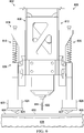
- FIG. 9 an illustration of a cross-sectional view of a machining system performing a machining operation on the sheet is depicted in accordance with an illustrative embodiment.
- machining tool 614 is performing a machining operation on sheet 606.
- machining tool 614 is drill bit 622 performing a drilling operation on sheet 606.
- Compression force 802 is applied to sheet 606 as the drilling operation is performed on sheet 606.
- Compression force 802 is applied to sheet 606 to form region 803 of applied compressive force. Machining tool 614 performs drilling in region 803.
- Machining tool 614 is independently moveable relative to spring back control system 616. More specifically, machining tool 614 is independently moveable relative to number of force generators 618 in first direction 902 parallel to number of force generators 618. Between view 800 and view 900, machining tool 614 has been moved in first direction 902 towards sheet 606.
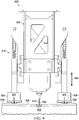
- FIG. 10 an illustration of a cross-sectional view of a machining system performing a machining operation on the sheet is depicted in accordance with an illustrative embodiment.
- drill bit 622 has completely perforated sheet 606.
- drill bit 622 is extending through sheet 606.
- compression force 802 is applied to sheet 606.
- Compression force 802 is applied in region 803 of sheet 606. Due to compression force 802 still being applied to sheet 606, sheet 606 is still in tension. Due to compression force 802, spring back of sheet 606 following the machining operation is reduced. Spring back of sheet 606 following the machining operation under compression force 802 is less than spring back of sheet 606 after a drilling operation without compression force 802.
- the spring back of sheet 606 after drill bit 622 perforates sheet 606 is not visible. In other illustrative examples, the spring back of sheet 606 after drill bit 622 perforates sheet 606 may be visible.
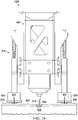
- FIG. 11 an illustration of a cross-sectional view of a machining system performing a machining operation on the sheet is depicted in accordance with an illustrative embodiment.
- drill bit 622 has been retracted in first direction 902 from sheet 606.
- Hole 1102 extends through sheet 606.
- compression force 802 is maintained on sheet 606.
- tension will be removed from sheet 606.
- spring back will occur in a controlled fashion. For example, at least one of the rate of the spring back or the initiation of spring back relative to machining operation is controlled.
- compression force 802 may be maintained on sheet 606 as roller 625 and roller 627 are rolled across surface 702 of sheet 606. In these illustrative examples, compression force 802 is maintained as end effector 612 is moved relative to sheet 606. In some of these illustrative examples, compression force 802 may be maintained as drill bit 622 performs machining operations on several locations of sheet 606.
- compression force 802 is removed prior to moving end effector 612 relative to sheet 606. In some of these illustrative examples, compression force 802 is applied prior to each instance of a machining operation and removed after each instance of the machining operation.
- Machining system 1200 is a physical implementation of machining system 100 of Figure 1 . Machining system 1200 is configured to reduce spring back following a machining operation. Machining system 1200 comprises number of linear force generators 1202, number of force loaded members 1204 coupled to number of linear force generators 1202, and machining tool 1206 independently moveable relative to number of linear force generators 1202 in a first direction parallel to number of linear force generators 1202. Number of force loaded members 1204 is configured to apply compression force to form a region of applied compressive force. Machining tool 1206 is positioned to perform a machining operation within the region.
- number of force loaded members 1204 is each equidistant from machining tool 1206. As depicted, number of force loaded members 1204 comprises pad 1208, pad 1210, and pad 1212. Number of linear force generators 1202 takes any desirable form. In some illustrative examples, number of linear force generators 1202 comprises at least one of a number of springs or a number of pneumatic cylinders.
- Machining tool 1206 is independently moveable in a second direction perpendicular to number of linear force generators 1202. As depicted, machining tool 1206 comprises drill bit 1214 having axis 1216 parallel to number of linear force generators 1202.
- machining system 1200 takes the form of end effector 1218.
- End effector 1218 is configured to reduce spring back following a machining operation.
- Machining system 1200 comprises machining tool 1206 and spring back control system 1220.
- Spring back control system 1220 comprises number of force generators 1222 and number of force loaded members 1204 coupled to number of force generators 1222.
- Each force loaded member of number of force loaded members 1204 comprises a material contact surface.
- pad 1208 of number of force loaded members 1204 has material contact surface 1224.
- Pad 1210 has material contact surface 1226 and pad 1212 has material contact surface 1228.
- each force generator of number of force generators 1222 is coupled to a different force loaded member of number of force loaded members 1204.
- each of number of force generators 1222 is coupled to a respective single force loaded member of pad 1208, pad 1210, or pad 1212.
- pad 1208, pad 1210, and pad 1212 form a triangle.
- machining tool 1206 will perform a machining operation on a workpiece within a triangular region of compressive force formed by pad 1208, pad 1210, and pad 1212. As can be seen in this illustrative example, machining tool 1206 will be positioned between pad 1208, pad 1210, and pad 1212.
- pad 1208, pad 1210, and pad 1212 are placed in contact with the surface of a workpiece.
- a compression force is applied to the workpiece using number of force generators 1222 to form a region of applied compressive force.
- a machining operation will be performed in the region using machining tool 1206 while the compression force is applied to the sheet.
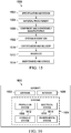
- Method 1300 may be implemented in manufacturing environment 102 of Figure 1 using machining system 100.
- Method 1300 may be implemented using machining system 200 of Figures 2 and 3 .
- Method 1300 may be implemented using machining system 400 of Figures 4-5 .
- Method 1300 may be implemented in manufacturing environment 605 using machining system 600 of Figures 6-11 .
- Method 1300 may be implemented using machining system 1200 of Figure 12 .
- Method 1300 applies a compression force to the sheet using a number of force generators coupled to a number of force loaded members in contact with the sheet to form a region of applied compressive force (operation 1302 ).
- Each of the force loaded members comprises a respective material contact surface.
- the material contact surface takes the form of one of a moveable surface or a stationary surface. When the material contact surface takes the form of a moveable surface, material contact surface may be part of a roller. When the material contact surface takes the form of a stationary surface, the material contact surface may be part of a pad.
- the number of force generators take any desirable form.
- the number of force generators are a number of linear force generators.
- Method 1300 completes a machining operation through the region of the surface of the sheet using a machining tool while the compression force is applied to the sheet (operation 1304 ).
- the machining operation may be drilling, milling, countersinking, or any other desirable form of machining operation. Afterwards, method 1300 terminates.
- the compression force is applied to the region of the sheet prior to performing the machining operation. In some illustrative examples, the compression force deflects the sheet such that the machining operation is performed on a desired location.
- applying the compression force to the region of the sheet comprises moving the number of force generators towards the surface of the sheet while the number of force loaded members is in contact with the surface of the sheet to compress the number of force generators (operation 1306 ).
- method 1300 moves the machining tool relative to the surface of the sheet while maintaining contact of the number of force loaded members with the surface of the sheet (operation 1308 ).
- moving the machining tool relative to the surface of the sheet while maintaining contact of the number of force loaded members with the surface of the sheet is performed to apply a machining operation to a second location within the region.
- moving the machining tool relative to the surface of the sheet while maintaining contact of the number of force loaded members with the surface of the sheet is performed when the machining operation is a countersinking operation.
- moving the machining tool relative to the surface of the sheet comprises moving the machining tool relative to the surface while performing the machining operation (operation 1310 ).
- method 1300 removes the machining tool from the sheet (operation 1312 ).
- the compression force is removed from the sheet (operation 1314 ) .
- the machining tool and force loaded members are moved relative to the surface of the sheet after removing the machining tool and the compression force from the sheet (operation 1316 ).
- a compression force is applied to a second portion of the sheet using the number of force generators coupled to the number of force loaded members to form a second region of applied compressive force (operation 1318 ) .
- the machining operation is performed through the second region of the surface of the sheet using the machining tool while the compression force is applied to the second portion of the sheet (operation 1320 ).
- Method 1400 may be implemented in manufacturing environment 102 of Figure 1 using machining system 100.
- Method 1400 may be implemented using machining system 200 of Figures 2 and 3 .
- Method 1400 may be implemented using machining system 400 of Figures 4- 5.
- Method 1400 may be implemented in manufacturing environment 605 using machining system 600 of Figures 6-11 .
- Method 1400 may be implemented using machining system 1200 of Figure 12 .
- Method 1400 deflects the thin sheet towards a support tool with an end effector (operation 1402 ). Method 1400 performs the machining operation on the thin sheet while deflected (operation 1404 ). Afterwards the method terminates.
- deflecting is performed by a number of biasing devices attached to a same end effector performing the machining operation (operation 1406 ) .
- the number of biasing devices is part of a spring back control system of the end effector.
- deflecting the thin sheet comprises deflecting the thin sheet a distance as a function of a compression force applied to the thin sheet by a number of force loaded members (operation 1408 ).
- the compression force applied is sufficient to temporarily deflect the thin sheet and lower than a force to permanently deflect the thin sheet.
- performing the machining operation comprises further deflecting the thin sheet by a machining force of the machining operation, wherein deflection from the machining force is less than deflection from the compression force applied by the number of force loaded members (operation 1410 ).
- the machining operation perforates the thin sheet and the machining force is no longer applied to the thin sheet, the spring back of the thin sheet is less because the thin sheet is still deflected by the compression force.
- the phrase "at least one of,” when used with a list of items, means different combinations of one or more of the listed items may be used, and only one of each item in the list may be needed. In other words, "at least one of' means any combination of items and number of items may be used from the list, but not all of the items in the list are required.
- the item may be a particular object, a thing, or a category.
- “at least one of item A, item B, or item C” may include, without limitation, item A, item A and item B, or item B. This example also may include item A, item B, and item C, or item B and item C. Of course, any combination of these items may be present. In other examples, "at least one of' may be, for example, without limitation, two of item A, one of item B, and ten of item C; four of item B and seven of item C; or other suitable combinations.
- each block in the flowcharts or block diagrams may represent a module, a segment, a function, and/or a portion of an operation or step.
- the function or functions noted in the blocks may occur out of the order noted in the figures. For example, in some cases, two blocks shown in succession may be executed substantially concurrently, or the blocks may sometimes be performed in the reverse order, depending upon the functionality involved. Also, other blocks may be added, in addition to the illustrated blocks, in a flowchart or block diagram. Some blocks may be optional. For example, in method 1300, operations 1308 through 1322 may be optional. As another example, in method 1400, operations 1406 through 1410 may be optional.
- aircraft manufacturing and service method 1500 may be described in the context of aircraft manufacturing and service method 1500 as shown in Figure 15 and aircraft 1600 as shown in Figure 16 .
- Figure 15 an illustration of an aircraft manufacturing and service method is depicted in accordance with an illustrative embodiment.
- aircraft manufacturing and service method 1500 may include specification and design 1502 of aircraft 1600 in Figure 16 and material procurement 1504.
- aircraft 1600 During production, component and subassembly manufacturing 1506 and system integration 1508 of aircraft 1600 takes place. Thereafter, aircraft 1600 may go through certification and delivery 1510 in order to be placed in service 1512. While in service 1512 by a customer, aircraft 1600 is scheduled for routine maintenance and service 1514, which may include modification, reconfiguration, refurbishment, or other maintenance and service.
- Each of the processes of aircraft manufacturing and service method 1500 may be performed or carried out by a system integrator, a third party, and/or an operator.
- the operator may be a customer.
- a system integrator may include, without limitation, any number of aircraft manufacturers and major-system subcontractors
- a third party may include, without limitation, any number of vendors, subcontractors, and suppliers
- an operator may be an airline, a leasing company, a military entity, a service organization, and so on.
- aircraft 1600 is produced by aircraft manufacturing and service method 1500 of Figure 15 and may include airframe 1602 with plurality of systems 1604 and interior 1606.
- systems 1604 include one or more of propulsion system 1608, electrical system 1610, hydraulic system 1612, and environmental system 1614. Any number of other systems may be included.
- propulsion system 1608 electrical system 1610, hydraulic system 1612, and environmental system 1614. Any number of other systems may be included.
- an aerospace example is shown, different illustrative embodiments may be applied to other industries, such as the automotive industry.
- Apparatuses and methods embodied herein may be employed during at least one of the stages of aircraft manufacturing and service method 1500.
- One or more illustrative embodiments may be used during at least one of component and subassembly manufacturing 1506, system integration 1508, or maintenance and service 1514 of Figure 15 .
- machining system 100 with spring back control system 106 may be used during component and subassembly manufacturing 1506 to form component 162.
- machining system 100 with spring back control system 106 may be used to form a replacement component for use in maintenance and service 1514.
- Machining system 100 may be used to manufacture portions of aircraft 1600 such as airframe 1602 or portions of interior 1606.
- the illustrative examples present machining systems and methods configured to reduce spring back following a machining operation.
- the illustrative examples provide a spring back control system configured to apply a compression force to a sheet. By applying the compression force to the sheet, a region of compressive force is formed. By performing a machining operation in the region of compressive force, spring back following completion of a machining operation is reduced or eliminated. By reducing or eliminating spring back, the quality of machined areas, such as holes or slots, is improved. By reducing or eliminating spring back, a risk to the machining tool is reduced.
- the spring back control system By incorporating the spring back control system into the machining system, at least one of the complexity, the time, or the cost of securing of the sheet to the support tool may be reduced. For example, by applying a compression force to the sheet using the spring back control system, adhesive may not be used to secure the sheet to the support tool. As another example, by applying a compression force to the sheet using the spring back control system, additional mechanical or vacuum attachments to the support tool may not be used.
- a number of biasing devices apply a load to a thin sheet.
- the thin sheet may reversibly deflect towards a support tool.
- a machining operation is completed on the thin sheet.
- the load is applied to the thin sheet prior to performing the machining operation.
- the location of a resulting feature created by the machining operation is desirably located. Deflecting the thin sheet prior to completing the machining operation reduces the spring back of the machining operation.
- Clause 2 The method of Clause 1 further comprising: moving the machining tool relative to the surface of the sheet while maintaining contact of the number of force loaded members with the surface of the sheet.
- Clause 3 The method of Clause 2, wherein moving the machining tool relative to the surface of the sheet comprises moving the machining tool relative to the surface while performing the machining operation.
- Clause 4 The method of any one of Clauses 1 to 3 further comprising: removing the machining tool from the sheet; removing the compression force from the sheet; moving the machining tool and force loaded members relative to the surface of the sheet after removing the machining tool and the compression force from the sheet; applying a compression force to a second portion of the sheet using the number of force generators coupled to the number of force loaded members to form a second region of applied compressive force; and completing the machining operation through the second region of the surface of the sheet using the machining tool while the compression force is applied to the second portion of the sheet.
- Clause 5 The method of any one of Clauses 1 to 4, wherein applying the compression force to the region of the sheet comprises moving the number of force generators towards the surface of the sheet while the number of force loaded members is in contact with the surface of the sheet to compress the number of force generators.
- a machining system configured to reduce spring back following a machining operation, the machining system comprising: a machining tool; and a spring back control system comprising a number of force generators and a number of force loaded members coupled to the number of force generators, each force loaded member of the number of force loaded members comprising a material contact surface.
- Clause 8 The machining system of Clause 6, wherein multiple force generators of the number of force generators are coupled to a single force loaded member of the number of force loaded members.
- each of the number of force loaded members further comprises a linear bearing and a carriage.
- Clause 11 The machining system of any one of Clauses 6 to 10, wherein each material contact surface is one of a roller or a pad.
- Clause 12 The machining system of any one of Clauses 6 to 11, wherein the machining tool comprises a drill bit.
- the number of force generators comprises a number of linear force generators
- the number of force loaded members is coupled to the number of linear force generators and configured to apply compression force to form a region of applied compressive force
- the machining tool is independently moveable relative to the number of linear force generators.
- a machining system configured to reduce spring back following a machining operation, the machining system comprising: a number of linear force generators; a number of force loaded members coupled to the number of linear force generators and configured to apply compression force to form a region of applied compressive force; and a machining tool independently moveable relative to the number of linear force generators.
- Clause 15 The machining system of Clause 13 or 14, wherein the machining tool is independently moveable relative to the number of linear force generators in a first direction parallel to the number of linear force generators, the machining tool positioned to perform a machining operation within the region.
- Clause 16 The machining system of any one of Clauses 13 to 15, wherein the number of force loaded members is each equidistant from the machining tool.
- Clause 17 The machining system of any one of Clauses 13 to 16, wherein the number of force loaded members comprises a pad configured to form a working envelope for the machining tool.
- Clause 18 The machining system of any one of Clauses 13 to 17, wherein the number of force loaded members comprises at least one of a number of rollers or a number of pads.
- Clause 19 The machining system of any one of Clauses 13 to 18, wherein the number of linear force generators comprises at least one of a number of springs or a number of pneumatic cylinders.
- Clause 20 The machining system of any one of Clauses 13 to 19, wherein the machining tool is independently moveable in a second direction perpendicular to the number of linear force generators.
- a method of reducing spring back of a thin sheet during a machining operation comprising: deflecting the thin sheet towards a support tool with an end effector; and performing the machining operation on the thin sheet while deflected.
- Clause 23 The method of Clause 22, wherein deflecting is performed by a number of biasing devices attached to a same end effector performing the machining operation.
- Clause 24 The method of Clause 22 or 23, wherein deflecting the thin sheet comprises deflecting the thin sheet a distance as a function of a compression force applied to the thin sheet by a number of force loaded members.
- Clause 25 The method of any one of Clauses 22 to 24, wherein deflecting is performed by a number of biasing devices, and wherein performing the machining operation comprises further deflecting the thin sheet by a machining force of the machining operation, wherein deflection from the machining force is less than deflection from a compression force applied by the number of biasing devices.
Landscapes
- Engineering & Computer Science (AREA)
- Mechanical Engineering (AREA)
- Perforating, Stamping-Out Or Severing By Means Other Than Cutting (AREA)
- Drilling And Boring (AREA)
- Jigs For Machine Tools (AREA)
- Control Of Cutting Processes (AREA)
Abstract
Description
- The present disclosure relates generally to machining operations on sheets, and more specifically to controlling spring back of a sheet of material following machining operations.
- During manufacturing of sheet components, machining operations, such as drilling, milling, countersinking, or any other desirable machining operation may be performed on a sheet of material. The initial machining force from the drill bit on an unsupported portion of a sheet and the resulting spring back of the sheet may result in less than desired hole quality. The initial machining force from the drill bit and the resulting spring back of the sheet can undesirably affect the drill bit, including potentially breaking the drill bit.
- Therefore, it would be desirable to have a method and apparatus that takes into account at least some of the issues discussed above, as well as other possible issues.
- An illustrative embodiment of the present disclosure provides a method of controlling spring back of a sheet of material following machining operation using a machining system. A surface of the sheet is contacted with a number of force loaded members. A compression force is applied to the sheet using a number of force generators coupled to the number of force loaded members to form a region of applied compressive force. A machining operation is performed through the region of the surface of the sheet using a machining tool while the compression force is applied to the sheet.
- Another illustrative embodiment of the present disclosure provides a machining system configured to reduce spring back following machining operation. The machining system comprises a machining tool, and a spring back control system comprising a number of force generators and a number of force loaded members coupled to the number of force generators. Each force loaded member of the number of force loaded members comprises a material contact surface.
- A further illustrative embodiment of the present disclosure provides a machining system configured to reduce spring back following a machining operation. The machining system comprises a number of linear force generators, a number of force loaded members coupled to the number of linear force generators, and a machining tool independently moveable relative to the number of linear force generators. The number of force loaded members are configured to apply compression force to form a region of applied compressive force. The machining tool is positioned to perform a machining operation within the region.
- A yet further illustrative embodiment of the present disclosure provides a method of reducing spring back of a thin sheet following a machining operation. The thin sheet is deflected towards a support tool with an end effector. The machining operation is performed on the thin sheet while deflected.
- The features and functions can be achieved independently in various embodiments of the present disclosure or may be combined in yet other embodiments in which further details can be seen with reference to the following description and drawings.
- The novel features believed characteristic of the illustrative embodiments are set forth in the appended claims. The illustrative embodiments, however, as well as a preferred mode of use, further objectives and features thereof, will best be understood by reference to the following detailed description of an illustrative embodiment of the present disclosure when read in conjunction with the accompanying drawings, wherein:
-
Figure 1 is an illustration of a block diagram of a manufacturing environment in which a machining system configured to reduce spring back following a machining operation is utilized in accordance with an illustrative embodiment; -
Figure 2 is an illustration of a perspective view of a machining system configured to reduce spring back following a machining operation in accordance with an illustrative embodiment; -
Figure 3 is an illustration of a bottom view of a machining system configured to reduce spring back following a machining operation in accordance with an illustrative embodiment; -
Figure 4 is an illustration of a side view of a machining system configured to reduce spring back following a machining operation in accordance with an illustrative embodiment; -
Figure 5 is an illustration of a front view of a machining system configured to reduce spring back following a machining operation in accordance with an illustrative embodiment; -
Figure 6 is an illustration of a front view of a machining system above a sheet in accordance with an illustrative embodiment; -
Figure 7 is an illustration of a front view of force loaded members of a machining system in contact with a sheet in accordance with an illustrative embodiment; -
Figure 8 is an illustration of a front view of force loaded members of a machining system applying a compression force to a sheet in accordance with an illustrative embodiment; -
Figure 9 is an illustration of a cross-sectional view of a machining system performing a machining operation on the sheet in accordance with an illustrative embodiment; -
Figure 10 is an illustration of a cross-sectional view of a machining system performing a machining operation on the sheet in accordance with an illustrative embodiment; -
Figure 11 is an illustration of a cross-sectional view of a machining system performing a machining operation on the sheet in accordance with an illustrative embodiment; -
Figure 12 is an illustration of a perspective view of a machining system configured to reduce spring back following a machining operation in accordance with an illustrative embodiment; -
Figure 13 is an illustration of a flowchart of a method for controlling spring back of a sheet of material following a machining operation using a machining system in accordance with an illustrative embodiment; -
Figure 14 is an illustration of a flowchart of a method of reducing spring back of a thin sheet during a machining operation in accordance with an illustrative embodiment; -
Figure 15 is an illustration of an aircraft manufacturing and service method in a form of a block diagram in accordance with an illustrative embodiment; and -
Figure 16 is an illustration of an aircraft in a form of a block diagram in which an illustrative embodiment may be implemented. - The illustrative embodiments recognize and take into account one or more different considerations. The illustrative embodiments recognize and take into account that prior to machining the sheet, the sheet is restrained against a backing plate style support tool. Often, the sheet is restrained at the periphery, leaving the remainder of the sheet unrestrained such that the restraint does not inhibit processing. While the periphery of sheet is restrained, the remainder of the sheet may bend such that portions of the sheet are not in contact with the support surface of the support tool. The portions of the sheet not in contact with the support surface are unsupported. While the periphery of the sheet is restrained against the support tool, a machining operation is performed on a portion of the sheet. The portion of the sheet to be machined may not be contacting the support tool and may be unsupported.
- The illustrative embodiments recognize and take into account that performing machining operations on an unsupported portion of the sheet results in spring back. For example, when using a conventional drill system to drill holes, the drill bit initially makes contact with the unsupported surface of the sheet and applies pressure to the sheet. The pressure, or machining force, applied from the drill bit initially causes the sheet to compress against the support tool prior to penetrating through the sheet. Once the sheet is completely penetrated, the elastic energy causes the sheet to rapidly spring back to its free state. This spring back of the sheet is uncontrolled.
- The sheet is pushed by the machining force of the drill bit in the direction of the support tool during the machining operation. After the drill bit passes through the sheet, the sheet is no longer subjected to the pushing machining force of the drill bit, and the sheet springs back to its original location.
- The illustrative embodiments recognize and take into account that a support tool desirably mirrors the shape of the sheet. The illustrative embodiments recognize and take into account that a support tool may not precisely mirror the shape of the sheet over the entirety of the support tool. The illustrative embodiments recognize and take into account that the support surface of the support tool may be non-planar to support the sheet. The illustrative embodiments recognize and take into account that restraining a sheet on a support tool may result in a gap between the support surface and the sheet.
- The illustrative embodiments recognize and take into account that in some examples the support surface of the support tool may be non-planar to support the sheet. In some illustrative examples, the non-planar support tool surface may be concave. When the support surface is non-planar, restraining the periphery of sheet causes the remainder of the sheet to bend such that portions of the sheet are not in contact with the support surface of the support tool. The illustrative embodiments recognize and take into account that a combination of the shape of the sheet and the shape of the support tool may cause gaps between the sheet and the support tool. The illustrative embodiments recognize and take into account that a gap may occur even when potential spring back energy is present in the sheet.
- The illustrative embodiments recognize and take into account that performing machining operations on an unsupported portion of the sheet may result in undesirable locations for the machining operations. The illustrative embodiments recognize and take into account that it may be desirable for the sheet to contact the support surface for desirable positioning of features created during the machining operations.
- The illustrative embodiments also recognize and take into account that to reduce spring back following a machining operation, a sheet of material may be tacked to a support tool using a temporary adhesive. However, adhesive residue may transfer to machining tools, such as drill bits. Adhesive residue on machining tools may undesirably affect at least one of the life of the machining tools, or the quality of the manufactured component. For example, adhesive residue may undesirably affect the quality of drilled holes in a manufactured component. The illustrative embodiments recognize and take into account that applying an adhesive adds time and cost to the manufacturing process.
- Additionally, an adhesive used to hold a sheet of material to a support tool would be qualified for contact use with the type of material of the sheet as well as the material of the support tool. It would be undesirable to use an adhesive that would damage either the material of the sheet or the material of the support tool. Depending upon the material of the sheet, there may be a limited quantity of qualified adhesives.
- In some manufacturing operations, vacuum is applied to a sheet to hold the sheet against a support tool. However, conventional vacuum plates having vacuum channels around the periphery do not apply vacuum to the center of the sheet where machining operations are performed. Machining operations, such as perforating processes, would diminish the effectiveness of conventional vacuum plates with vacuum channels in the region of machining operations.
- The illustrative embodiments recognize and take into account that conventional methods of attempting to reduce spring back include methods of holding the sheet against the support tool. Conventional methods of attempting to reduce spring back include methods of increasing the supported surface of the sheet around the periphery of the sheet.
- The illustrative embodiments recognize and take into account that uncontrolled spring back occurs when a sheet is placed into tension by a machining force and the tension is uncontrollably released after a machining tool passes through the sheet and the machining force is no longer applied to the sheet. The illustrative embodiments recognize and take into account that if the release of tension in the sheet were to be controlled, the spring back would be controlled.
- The illustrative embodiments provide machining systems and methods for reducing spring back in machining operations. The illustrative embodiments apply a compression force to the surface of the sheet as the machining operation is performed on the surface of the sheet. By applying the compression force, spring back of the sheet following the machining operation is reduced or eliminated. In some illustrative embodiments, a number of biasing devices apply a load to the sheet to deflect the sheet prior to a machining operation such that spring back following the machining operation is reduced to within desirable limits. After removing the compression force, the sheet experiences a controlled spring back to its original shape. At least one of the rate of spring back or the initiation of spring back relative to the machining operation is controlled.
- Turning now to
Figure 1 , an illustration of a block diagram of a manufacturing environment in which a machining system configured to reduce spring back following a machining operation is utilized is depicted in accordance with an illustrative embodiment.Machining system 100 inmanufacturing environment 102 is configured to reduce spring back following a machining operation. -
Machining system 100 comprisesmachining tool 104 and spring backcontrol system 106. Spring backcontrol system 106 comprises number offorce generators 108 and number of force loadedmembers 110 coupled to number offorce generators 108. Each force loaded member of number of force loadedmembers 110 comprises a material contact surface. For example, force loadedmember 111 comprisesmaterial contact surface 113. - As used herein, a "number of' items means one or more items. For example, a number of force loaded members means one or more force loaded members.
-
Material contact surface 113 is formed of any desirable material.Material contact surface 113 is configured to not undesirably affectsurface 122 ofsheet 120. In one example, the shape ofmaterial contact surface 113 is selected to not undesirably mar, bend, ormark surface 122 ofsheet 120. As another example, the material ofmaterial contact surface 113 is selected to not undesirably mar, bend, ormark surface 122 ofsheet 120. In another illustrative example, the material ofmaterial contact surface 113 is selected to slip relative tosurface 122. In another illustrative example, the material ofmaterial contact surface 113 is selected to grip and maintain the position ofmaterial contact surface 113 relative to surface 122. -
Machining tool 104 comprises any desirable type of tool. In some illustrative examples,machining tool 104 comprises a cutting tool. In one illustrative example,machining tool 104 comprisesdrill bit 112. In other illustrative examples,machining tool 104 may be selected from a blade, a punch, a mill, or any other desirable cutting tool. In other illustrative examples,machining tool 104 may be selected from a joining tool, a welding tool, or any other desirable type of tool. - In some illustrative examples,
machining tool 104 is independently moveable relative to spring backcontrol system 106. In some illustrative examples,machining tool 104 is independently moveable relative to number offorce generators 108. In one illustrative example,machining tool 104 is independently moveable relative to spring backcontrol system 106 infirst direction 114.First direction 114 is parallel to application ofcompression force 116.Compression force 116 applied by spring backcontrol system 106 tosheet 120 is parallel tofirst direction 114 and application of force tosheet 120 by machiningtool 104. In another illustrative examples,machining tool 104 is independently moveable relative to spring backcontrol system 106 insecond direction 118 perpendicular tofirst direction 114. - When machining
tool 104 is independently moveable relative to spring backcontrol system 106,machining tool 104 may be used to perform machining operations such as slotting or countersinking that may involve movement ofmachining tool 104 insecond direction 118. When machiningtool 104 is independently moveable relative to spring backcontrol system 106,machining tool 104 may be used to perform multiple machining operation instances without moving spring backcontrol system 106 relative tosheet 120. - Spring back
control system 106 providescompression force 116 againstsheet 120. Spring backcontrol system 106 providescompression force 116 to surface 122 ofsheet 120 to formregion 124 of applied compressive force. Machining operations, such asmachining operation 126, are performed inregion 124. Machining operations take any desirable form including drilling, milling, countersinking, or any other desirable machining operation. -
Sheet 120 is formed ofmaterial 128.Material 128 takes the form of any desirable material that haselastic deformation 130. During machiningoperation 126, force applied by machiningtool 104placing sheet 120 in tension until machiningtool 104 penetratessheet 120. In some illustrative examples,material 128 is one ofmetal 132 orcomposite material 134. Whenmaterial 128 iscomposite material 134,composite material 134 is cured or partially cured. - In some illustrative examples,
sheet 120 is referred to asthin sheet 136.Sheet 120 may be referred to asthin sheet 136, assheet 120 is thin enough to deflect when machining force ofmachining operation 126 is applied tosheet 120 withoutcompression force 116 applied. -
Sheet 120 is restrained againstsupport tool 138. In some illustrative examples, whensheet 120 is restrained againstsupport tool 138,gap 140 is present between portions ofsheet 120 andsupport surface 142 ofsupport tool 138. In some illustrative examples,gap 140 is present due toconcave curvature 144 ofsupport surface 142.Gap 140 is not present behind the entirety ofsheet 120, but is present behind at least some of the locations wheremachining operation 126 will be performed. - If
machining operation 126 were performed onsurface 122 withoutcompression force 116 from spring backcontrol system 106, spring back 146 followingmachining operation 126 may have an undesirable force. Ifmachining operation 126 were performed onsurface 122 withoutcompression force 116 from spring backcontrol system 106, spring back 146 is uncontrolled. By applyingcompression force 116 to surface 122 asmachining operation 126 is performed, spring back 146 followingmachining operation 126 is reduced. Spring backcontrol system 106 reduces spring back 146 followingmachining operation 126 to at or below a desired threshold. Specifically, spring back 146 from machiningoperation 126 whencompression force 116 is applied is less than the spring back experienced whencompression force 116 is not applied duringmachining operation 126. In some illustrative examples, spring back 146 followingmachining operation 126 is eliminated whencompression force 116 is applied duringmachining operation 126. -
Compression force 116 applied to surface 122 is sufficient to desirably reduce spring back 146 ofsheet 120 followingmachining operation 126.Compression force 116 is not high enough to cause permanent deformation tosheet 120. In some illustrative examples,compression force 116 is configured to be sufficient to causesheet 120 to contactsupport surface 142 ofsupport tool 138 inregion 124 of compressive force. Number offorce generators 108 are selected to apply a desired amount ofcompression force 116. In some illustrative examples, number offorce generators 108 are removable and interchangeable so that force generators of a desired strength can be introduced to spring backcontrol system 106. - In some illustrative examples, when
compression force 116 is applied to surface 122 ofsheet 120,sheet 120 deflects towardssupport surface 142 ofsupport tool 138. Whensheet 120 deflects towardssupport surface 142,gap 140 is reduced. By maintainingcompression force 116 followingmachining operation 126,sheet 120 returns to its original shape in a controlled fashion. - When
compression force 116 deflectssheet 120 towardssupport surface 142, a machining force ofmachining operation 126 deflectssheet 120 towardssupport surface 142 less than the deflection bycompression force 116.Machining operation 126 is performed onsheet 120 whilecompression force 116 is applied tosheet 120. After machiningtool 104 extends throughsheet 120, the machining force is no longer applied tosheet 120 and any deflection ofsheet 120 from machiningoperation 126 results in spring back 146. Spring back 146 is less whencompression force 116 is applied.Compression force 116 is removed after machiningoperation 126 is complete. Whencompression force 116 is removed,sheet 120 returns to its shape due toelastic deformation 130. - When
compression force 116 is removed, spring back 147 ofsheet 120 occurs assheet 120 returns to its original shape. Spring back 147 may also be referred to as a "controlled spring back." At least one of the rate of spring back 147 or the initiation of spring back 147 relative tomachining operation 126 is controlled. In some illustrative examples, spring back 147 occurs locally ascompression force 116 is removed locally, butcompression force 116 is maintained againstsheet 120 ascompression force 116 moves acrosssheet 120. In some illustrative examples, spring back 147 occurs for all ofsheet 120 ascompression force 116 is removed fromsheet 120. - Spring back
control system 106 appliescompression force 116. Number offorce generators 108 of spring backcontrol system 106 provide force to number of force loadedmembers 110 coupled to number offorce generators 108. Number offorce generators 108 takes any desirable form. In some illustrative examples, number offorce generators 108 is number oflinear force generators 148. Number oflinear force generators 148 is a number of force generators configured to apply a force in a linear direction. Number oflinear force generators 148 need not be linear in shape. In some illustrative examples, number oflinear force generators 148 comprises at least one of a number of springs or a number of pneumatic cylinders. In some illustrative examples, number offorce generators 108 is referred to as number of biasingdevices 149. Number of biasingdevices 149 providescompression force 116 applied tosheet 120 to reduce spring back 146 occurring from machiningoperation 126. By applyingcompression force 116, tension onsheet 120 introduced by machiningoperation 126 is reduced. By applyingcompression force 116,sheet 120 moves towardssupport tool 138. In some illustrative examples,compression force 116 is maintained onsheet 120 as multiple instances ofmachining operation 126 are performed onsheet 120. In some illustrative examples,compression force 116 is removed fromsheet 120 after each instance ofmachining operation 126. - Each force loaded member of number of force loaded
members 110 is associated with a respective force generator of number offorce generators 108. In some illustrative examples, multiple force generators of number offorce generators 108 are coupled to a single force loaded member of number of force loadedmembers 110. In some illustrative examples, each force generator of number offorce generators 108 is coupled to a single respective force loaded member of number of force loadedmembers 110. - Number of force loaded
members 110 comprises at least one of a number of rollers or a number of pads. Each force loaded member of number of force loadedmembers 110 comprises a respective material contact surface,material contact surface 113. Eachmaterial contact surface 113 is one ofroller 150 orpad 152. - In some illustrative examples, when
material contact surface 113 isroller 150,roller 150 may remain in contact withsurface 122 ofsheet 120 asmachining system 100 moves insecond direction 118. In some illustrative examples, whenmaterial contact surface 113 isroller 150,roller 150 may remain in contact withsurface 122 ofsheet 120 asmachining operation 126 is performed at multiple locations ofsheet 120. - In some illustrative examples, when
material contact surface 113 ispad 152,pad 152 is removed fromsurface 122 ofsheet 120 prior to movement ofmachining system 100 insecond direction 118. In some illustrative examples, whenmaterial contact surface 113 ispad 152,machining tool 104 moves relative to pad 152 while machiningtool 104 performs machiningoperation 126. In some illustrative examples,machining tool 104 moves insecond direction 118 relative to pad 152 while machiningtool 104 performs countersinking, routing, slotting, or any other desirable machining operation. - In some illustrative examples, number of force loaded
members 110 andmachining tool 104 move infirst direction 114 towardssurface 122 simultaneously to performmachining operation 126. In some illustrative examples,machining tool 104 moves infirst direction 114 to performmachining operation 126 after number of force loadedmembers 110contact surface 122 and applycompression force 116. - In some illustrative examples, number of force loaded
members 110 includes a plurality of force loaded members. In some of these illustrative examples, number of force loadedmembers 110 comprises a plurality of pads configured to applycompression force 116 to surface 122 ofsheet 120 to formregion 124 of applied compressive force. In these illustrative examples,region 124 is substantially between number of force loadedmembers 110. In these illustrative examples, number of force loadedmembers 110 are removed fromsurface 122 prior to movingmachining system 100 insecond direction 118. In these illustrative examples, number of force loadedmembers 110 are removed from contact withsheet 120 after dampening spring back 146 from machiningoperation 126. - In some illustrative examples, number of force loaded
members 110 includes a single force loaded member. In some of these illustrative examples, number of force loadedmembers 110 comprises a single pad,pad 152. In these illustrative examples, number of force loadedmembers 110 comprisespad 152 configured to form workingenvelope 153 formachining tool 104. When number of force loadedmembers 110 comprisespad 152 with workingenvelope 153,machining tool 104 performs machiningoperation 126 through workingenvelope 153. In one illustrative example,machining tool 104 isdrill bit 112, anddrill bit 112 extends through workingenvelope 153 to performmachining operation 126 onsheet 120. In some illustrative examples,machining tool 104 may performmachining operation 126 in multiple locations onsheet 120 without movingpad 152. - In some illustrative examples, each of number of force loaded
members 110 further compriseslinear bearing 154 andcarriage 156. In some illustrative examples, when present,linear bearing 154 andcarriage 156 restricts movement of number of force loadedmembers 110 tofirst direction 114. In some illustrative examples, when present,linear bearing 154 andcarriage 156 restricts movement of number of force loadedmembers 110 insecond direction 118. When present,linear bearing 154 andcarriage 156 restrict application ofcompression force 116 tofirst direction 114. - In some illustrative examples,
machining system 100 comprises number oflinear force generators 148, number of force loadedmembers 110 coupled to number oflinear force generators 148 and configured to applycompression force 116 to formregion 124 of applied compressive force, andmachining tool 104 independently moveable relative to number oflinear force generators 148 infirst direction 114 parallel to number oflinear force generators 148.Machining tool 104 is positioned to performmachining operation 126 withinregion 124. - In some illustrative examples, number of force loaded
members 110 is each equidistant frommachining tool 104. In one illustrative example, number of force loadedmembers 110 may be three force loaded members arranged in a triangle. In this illustrative example,machining tool 104 may be centered within the triangle formed by number of force loadedmembers 110. In another illustrative example, number of force loadedmembers 110 may be two force loaded members. In this illustrative example,machining tool 104 may be positioned between force loadedmembers 110. In yet another illustrative example, number of force loadedmembers 110 may be four force loaded members positioned in a rectangular or square pattern. In this illustrative example,machining tool 104 is centered within the rectangle or square formed by the four force loaded members. - In some illustrative examples, number of force loaded
members 110 comprisespad 152 configured to form workingenvelope 153 formachining tool 104. In these illustrative examples,pad 152 may also be referred to as a "foot". In these illustrative examples,pad 152 may be connected to multiple force generators of number offorce generators 108. - In some illustrative examples,
machining tool 104 is independently moveable insecond direction 118 perpendicular to number oflinear force generators 148. When machiningtool 104 is independently moveable insecond direction 118,machining tool 104 is independently moveable alongsurface 122 ofsheet 120. In some illustrative examples,machining tool 104 is moved insecond direction 118 while number of force loadedmembers 110contact surface 122 and applycompression force 116. In these illustrative examples,machining tool 104 may be used to form a slot, a channel, a hole larger than themachining tool 104, or any other desirable feature. In some illustrative examples,machining tool 104 comprisesdrill bit 112 havingaxis 158 parallel to number oflinear force generators 148. In some illustrative examples,machining tool 104 comprisesdrill bit 112 havingaxis 158 parallel tofirst direction 114. - In some illustrative examples,
machining system 100 takes the form ofend effector 160. In some illustrative examples,end effector 160 is connected to any desirable robotic device, such as a robotic arm. -
Machining system 100 performs machiningoperation 126 onsheet 120 to formcomponent 162.Component 162 is a component of any desirable platform. The platform may be, for example, a vehicle, a mobile platform, a stationary platform, a land-based structure, an aquatic-based structure, or a space-based structure. More specifically, a platform may be a surface ship, a tank, a personnel carrier, a train, a spacecraft, a space station, a satellite, a submarine, an automobile, a power plant, a bridge, a dam, a house, a manufacturing facility, a building, or other suitable platforms. In some illustrative examples, the platform takes the form of an aircraft. In these illustrative examples,component 162 isaircraft component 164. -
Component 162 has at least one feature formed by machiningtool 104 inmachining operation 126. For example,component 162 may have a plurality of slots, a plurality of channels, a plurality of holes, or any other desired feature. In some illustrative examples,component 162 is a perforated component. In some illustrative examples,component 162 takes the form ofdampener 166.Dampener 166 may be an acoustic dampener, a pressure dampener, or any other type of dampener. In some illustrative examples,component 162 is a face sheet of a sandwich panel structure. The illustration ofmanufacturing environment 102 andmachining system 100 inFigure 1 is not meant to imply physical or architectural limitations to the manner in which an illustrative embodiment may be implemented. Other components in addition to or in place of the ones illustrated may be used. Some components may be unnecessary. Also, the blocks are presented to illustrate some functional components. One or more of these blocks may be combined, divided, or combined and divided into different blocks when implemented in an illustrative embodiment. - For example, although only force loaded
member 111 is depicted within number of force loadedmembers 110, number of force loadedmembers 110 has any desirable quantity of force loaded members. For example, number of force loadedmembers 110 may include two, three, four, or more than four force loaded members. Each force loaded member of number of force loadedmembers 110 comprises a pad or a roller. - As another example, other non-depicted components or systems of
machining system 100 may be present inmachining system 100. For example, a debris removal system may be present to remove any debris generated by machiningoperation 126. As another example, utility connections and other components may be present to supportmachining system 100. As yet another example,material 128 may be another type of material havingelastic deformation 130, such as a polymeric material. - Although not depicted, in some illustrative examples, spring back
control system 106 may further comprise force adjusters configured to adjust an amount ofcompression force 116 applied. The force adjusters could be manual or automated. - Additionally, although
only end effector 160 is depicted, in some illustrative examples,machining system 100 includes more than one end effector. In some illustrative examples, spring backcontrol system 106 is part of a first end effector while machiningtool 104 is a component of a second end effector. - Turning now to
Figure 2 , an illustration of a perspective view of a machining system configured to reduce spring back following a machining operation is depicted in accordance with an illustrative embodiment.Machining system 200 is a physical implementation ofmachining system 100 ofFigure 1 .Machining system 200 is configured to reduce spring back following a machining operation.Machining system 200 reduces spring back from a machining operation by applying a compression force to a sheet until the machining operation is completed. When the machining force of the machining operation is removed, spring back following the machining operation is at or below a desired threshold. Controlled spring back of the sheet occurs when the compression force is removed from the sheet. -
Machining system 200 comprises number oflinear force generators 202, number of force loadedmembers 204 coupled to number oflinear force generators 202, andmachining tool 206 independently moveable relative to number oflinear force generators 202 infirst direction 208 parallel to number oflinear force generators 202. Number of force loadedmembers 204 is configured to apply compression force to form a region of applied compressive force.Machining tool 206 is positioned to perform a machining operation within the region. - As depicted, number of force loaded
members 204 is each equidistant frommachining tool 206. As depicted, number of force loadedmembers 204 comprisespad 210 configured to form workingenvelope 212 formachining tool 206. Number oflinear force generators 202 takes any desirable form. In some illustrative examples, number oflinear force generators 202 comprises at least one of a number of springs or a number of pneumatic cylinders. -
Machining tool 206 is independently moveable insecond direction 214 perpendicular to number oflinear force generators 202. As depicted,machining tool 206 comprisesdrill bit 216 havingaxis 218 parallel to number oflinear force generators 202. - As depicted,
machining system 200 takes the form ofend effector 220.End effector 220 is configured to reduce spring back following a machining operation. -
Machining system 200 comprisesmachining tool 206 and spring backcontrol system 222. Spring backcontrol system 222 comprises number offorce generators 224 and number of force loadedmembers 204 coupled to number offorce generators 224. Each force loaded member of number of force loadedmembers 204 comprises a material contact surface. As depicted,pad 210 of number of force loadedmembers 204 has material contact surface 226. - In
end effector 220, multiple force generators of number offorce generators 224 are coupled to a single force loaded member of number of force loadedmembers 204. Inend effector 220, each of number offorce generators 224 is coupled to a single force loadedmember comprising pad 210. - Turning now to
Figure 3 , an illustration of a bottom view of a machining system configured to reduce spring back following a machining operation is depicted in accordance with an illustrative embodiment. Inview 300, workingenvelope 212 ofpad 210 is visible. As can be seen inview 300,machining tool 206 will move infirst direction 208 ofFigure 2 to extend through workingenvelope 212 to perform a machining operation on a workpiece. Inview 300,first direction 208 ofFigure 2 moves into and out of the page. - To reduce spring back following a machining operation using
machining tool 206,pad 210 is placed in contact with the surface of a workpiece. A compression force is applied to the workpiece using number offorce generators 224 to form a region of applied compressive force. A machining operation will be performed in the region usingmachining tool 206 while the compression force is applied to the sheet. - Turning now to
Figure 4 , an illustration of a side view of a machining system configured to reduce spring back following a machining operation is depicted in accordance with an illustrative embodiment.Machining system 400 is a physical implementation ofmachining system 100 ofFigure 1 .Machining system 400 is a second non-limiting example ofmachining system 100 ofFigure 1 .Machining system 400 is configured to reduce spring back following a machining operation. -
Machining system 400 comprisesmachining tool 402 and spring backcontrol system 404. Spring backcontrol system 404 comprises number offorce generators 406 and number of force loadedmembers 408 coupled to number offorce generators 406. Each force loaded member of number of force loadedmembers 408 comprises a material contact surface. - For example, force loaded
member 410 of number of force loadedmembers 408 comprisesmaterial contact surface 412. Each material contact surface is one of a roller or a pad.Material contact surface 412 takes the form ofroller 414. - As depicted, each of number of force loaded
members 408 ofmachining system 400 comprises a linear bearing and a carriage. For example, force loadedmember 410 compriseslinear bearing 416 andcarriage 418. Linear bearing 416 andcarriage 418 restrict movement of force loadedmember 410 tofirst direction 420. -
Machining system 400 comprises number oflinear force generators 422, number of force loadedmembers 408 coupled to number oflinear force generators 422 and configured to apply a compression force to form a region of applied compressive force, andmachining tool 402 independently moveable relative to the number oflinear force generators 422 infirst direction 420 parallel to the number of linear force generators,machining tool 402 is positioned to perform a machining operation within the region. In some illustrative examples,machining tool 402 is independently moveable in a second direction perpendicular to number oflinear force generators 422. - Turning now to
Figure 5 , an illustration of a front view of a machining system configured to reduce spring back following a machining operation is depicted in accordance with an illustrative embodiment. View 500 is a front view ofmachining system 400 ofFigure 4 . - In view 500, force loaded
member 502 is visible. Force loadedmember 502 of number of force loadedmembers 408 comprisesmaterial contact surface 504.Material contact surface 504 takes the form ofroller 506. - In this illustrative example, each force loaded member of number of force loaded
members 408 is associated with a respective force generator of number offorce generators 406. For example,force generator 508 is associated with force loadedmember 410 andforce generator 510 is associated with force loadedmember 502. - Each of
force generator 508 andforce generator 510 provides a desirable amount of force to control spring back of a sheet of material following a machining operation. Each offorce generator 508 andforce generator 510 may be selected based on a desired amount of force. As depicted, number offorce generators 406 further comprisesforce adjuster 518 andforce adjuster 520. As depicted,force adjuster 518 andforce adjuster 520 may be loosened or tightened to adjust the pre-load for number offorce generators 406. - As depicted,
machining tool 402 comprisesdrill bit 512. As depicted,drill bit 512 hasaxis 514. As depicted, number offorce generators 406 takes the form of number oflinear force generators 422. As depicted,axis 514 is parallel to number oflinear force generators 422. As depicted,machining tool 402 is positioned betweenroller 414 androller 506. As depicted, number of force loadedmembers 408 is each equidistant frommachining tool 402. In some illustrative examples, number of force loadedmembers 408 is not equidistant frommachining tool 402. - As depicted,
machining tool 402 comprisesdrill bit 512 having anaxis 514 parallel to number oflinear force generators 422. In some illustrative examples,machining tool 402 is independently moveable relative to spring backcontrol system 404. - As depicted, number of
linear force generators 422 comprises at least one of a number of springs or a number of pneumatic cylinders. As depicted, number oflinear force generators 422 comprises number ofsprings 516. - Turning now to
Figure 6 , an illustration of a front view of a machining system above a sheet is depicted in accordance with an illustrative embodiment.Machining system 600 is a physical implementation ofmachining system 100 ofFigure 1 .Machining system 600 may be the same asmachining system 400 ofFigures 4-5 . - In
view 602,machining system 600 is positioned aboveworkpiece 604 inmanufacturing environment 605.Workpiece 604 takes the form ofsheet 606.Sheet 606 is associated withsupport tool 608.Sheet 606 is associated withsupport tool 608 by being restrained relative to supporttool 608.Sheet 606 is restrained relative to supporttool 608 by securing the periphery (not depicted) ofsheet 606 relative to supporttool 608. View 602 is of a portion ofsheet 606 that will receive a machining operation. - The periphery of
sheet 606 will not receive a machining operation. The description of securing periphery is only illustrative, any desirable amount ofsheet 606 is restrained againstsupport tool 608.Portion 610 ofsheet 606 is not in contact withsupport tool 608.Portion 610 ofsheet 606 is unsupported. -
Machining system 600 takes the form ofend effector 612.End effector 612 is configured to reduce spring back following a machining operation.Machining system 600 comprisesmachining tool 614 and spring backcontrol system 616. Spring backcontrol system 616 comprises number offorce generators 618 and number of force loadedmembers 620 coupled to number offorce generators 618. Each force loaded member of number of force loadedmembers 620 comprises a material contact surface. As depicted, each material contact surface is a roller. For example, force loadedmember 624 comprisesroller 625. As another example, force loadedmember 628 comprisesroller 627. - As depicted,
machining tool 614 comprisesdrill bit 622. Each force loaded member of number of force loadedmembers 620 is associated with a respective force generator of number offorce generators 618. For example, force loadedmember 624 of number of force loadedmembers 620 is associated withforce generator 626 of number offorce generators 618. As another example, force loadedmember 628 of number of force loadedmembers 620 is associated withforce generator 630 of number offorce generators 618. - Prior to performing a machining operation on
sheet 606 usingdrill bit 622, a compression force will be applied tosheet 606 by spring backcontrol system 616. A compression force applied by spring backcontrol system 616 will reduce the spring back ofsheet 606 caused by a machining operation onsheet 606. The compression force is applied in anticipation of a spring back ofsheet 606. - Turning now to
Figure 7 , an illustration of a front view of force loaded members of a machining system in contact with a sheet is depicted in accordance with an illustrative embodiment. Inview 700,roller 625 androller 627 are in contact withsurface 702 ofsheet 606.Machining tool 614 is not in contact withsurface 702. Inview 700,gap 704 is present betweensheet 606 andsupport tool 608. - In
view 700, a compression force is not yet allowed to surface 702. Inview 700,roller 625 androller 627 are in contact withsurface 702 but do not yet apply a force tosheet 606. - Turning now to
Figure 8 , an illustration of a front view of force loaded members of a machining system applying a compression force to a sheet is depicted in accordance with an illustrative embodiment. Inview 800,compression force 802 is applied tosheet 606 using number offorce generators 618 coupled to number of force loadedmembers 620 to formregion 803 of applied compressive force. - In
view 800,compression force 802 deflectssheet 606 towardssupport tool 608. By deflectingsheet 606 towardssupport tool 608,sheet 606 is placed into tension. By deflectingsheet 606 towardssupport tool 608,gap 704 betweensheet 606 andsupport tool 608 is reduced betweenview 700 ofFigure 7 andview 800. Inview 800, no visible gap is present betweensheet 606 andsupport tool 608. However,view 800 is not meant to imply physical or architectural limitations to the manner in which an illustrative embodiment may be implemented. In other illustrative examples, a small gap may still be present after application ofcompression force 802. Further,support tool 608 may have any desirable contour. Yet further, in some illustrative examples,compression force 802 may not be applied tosheet 606 prior to beginning a machining operation. - Turning now to
Figure 9 , an illustration of a cross-sectional view of a machining system performing a machining operation on the sheet is depicted in accordance with an illustrative embodiment. Inview 900,machining tool 614 is performing a machining operation onsheet 606. As depicted,machining tool 614 isdrill bit 622 performing a drilling operation onsheet 606.Compression force 802 is applied tosheet 606 as the drilling operation is performed onsheet 606. -
Compression force 802 is applied tosheet 606 to formregion 803 of applied compressive force.Machining tool 614 performs drilling inregion 803. -
Machining tool 614 is independently moveable relative to spring backcontrol system 616. More specifically,machining tool 614 is independently moveable relative to number offorce generators 618 infirst direction 902 parallel to number offorce generators 618. Betweenview 800 andview 900,machining tool 614 has been moved infirst direction 902 towardssheet 606. - Turning now to
Figure 10 , an illustration of a cross-sectional view of a machining system performing a machining operation on the sheet is depicted in accordance with an illustrative embodiment. Inview 1000,drill bit 622 has completely perforatedsheet 606. Inview 1000,drill bit 622 is extending throughsheet 606. - In
view 1000,compression force 802 is applied tosheet 606.Compression force 802 is applied inregion 803 ofsheet 606. Due tocompression force 802 still being applied tosheet 606,sheet 606 is still in tension. Due tocompression force 802, spring back ofsheet 606 following the machining operation is reduced. Spring back ofsheet 606 following the machining operation undercompression force 802 is less than spring back ofsheet 606 after a drilling operation withoutcompression force 802. Inview 1000, the spring back ofsheet 606 afterdrill bit 622 perforatessheet 606 is not visible. In other illustrative examples, the spring back ofsheet 606 afterdrill bit 622 perforatessheet 606 may be visible. - Turning now to
Figure 11 , an illustration of a cross-sectional view of a machining system performing a machining operation on the sheet is depicted in accordance with an illustrative embodiment. Inview 1100,drill bit 622 has been retracted infirst direction 902 fromsheet 606.Hole 1102 extends throughsheet 606. Inview 1100,compression force 802 is maintained onsheet 606. Ascompression force 802 is removed fromsheet 606, tension will be removed fromsheet 606. Ascompression force 802 is removed fromsheet 606, spring back will occur in a controlled fashion. For example, at least one of the rate of the spring back or the initiation of spring back relative to machining operation is controlled. - In some illustrative examples,
compression force 802 may be maintained onsheet 606 asroller 625 androller 627 are rolled acrosssurface 702 ofsheet 606. In these illustrative examples,compression force 802 is maintained asend effector 612 is moved relative tosheet 606. In some of these illustrative examples,compression force 802 may be maintained asdrill bit 622 performs machining operations on several locations ofsheet 606. - In other illustrative examples,
compression force 802 is removed prior to movingend effector 612 relative tosheet 606. In some of these illustrative examples,compression force 802 is applied prior to each instance of a machining operation and removed after each instance of the machining operation. - Turning now to
Figure 12 , an illustration of a perspective view of a machining system configured to reduce spring back following a machining operation is depicted in accordance with an illustrative embodiment.Machining system 1200 is a physical implementation ofmachining system 100 ofFigure 1 .Machining system 1200 is configured to reduce spring back following a machining operation.Machining system 1200 comprises number oflinear force generators 1202, number of force loadedmembers 1204 coupled to number oflinear force generators 1202, andmachining tool 1206 independently moveable relative to number oflinear force generators 1202 in a first direction parallel to number oflinear force generators 1202. Number of force loadedmembers 1204 is configured to apply compression force to form a region of applied compressive force.Machining tool 1206 is positioned to perform a machining operation within the region. - As depicted, number of force loaded
members 1204 is each equidistant frommachining tool 1206. As depicted, number of force loadedmembers 1204 comprisespad 1208,pad 1210, andpad 1212. Number oflinear force generators 1202 takes any desirable form. In some illustrative examples, number oflinear force generators 1202 comprises at least one of a number of springs or a number of pneumatic cylinders. -
Machining tool 1206 is independently moveable in a second direction perpendicular to number oflinear force generators 1202. As depicted,machining tool 1206 comprisesdrill bit 1214 havingaxis 1216 parallel to number oflinear force generators 1202. - As depicted,
machining system 1200 takes the form ofend effector 1218.End effector 1218 is configured to reduce spring back following a machining operation. -
Machining system 1200 comprisesmachining tool 1206 and spring backcontrol system 1220. Spring backcontrol system 1220 comprises number offorce generators 1222 and number of force loadedmembers 1204 coupled to number offorce generators 1222. Each force loaded member of number of force loadedmembers 1204 comprises a material contact surface. As depicted,pad 1208 of number of force loadedmembers 1204 hasmaterial contact surface 1224.Pad 1210 hasmaterial contact surface 1226 andpad 1212 hasmaterial contact surface 1228. - In
end effector 1218, each force generator of number offorce generators 1222 is coupled to a different force loaded member of number of force loadedmembers 1204. Inend effector 1218, each of number offorce generators 1222 is coupled to a respective single force loaded member ofpad 1208,pad 1210, orpad 1212. - In this illustrative example,
pad 1208,pad 1210, andpad 1212 form a triangle. As can be seen in this illustrative example,machining tool 1206 will perform a machining operation on a workpiece within a triangular region of compressive force formed bypad 1208,pad 1210, andpad 1212. As can be seen in this illustrative example,machining tool 1206 will be positioned betweenpad 1208,pad 1210, andpad 1212. - To reduce spring back following a machining operation using
machining tool 1206,pad 1208,pad 1210, andpad 1212 are placed in contact with the surface of a workpiece. A compression force is applied to the workpiece using number offorce generators 1222 to form a region of applied compressive force. A machining operation will be performed in the region usingmachining tool 1206 while the compression force is applied to the sheet. - Turning now to
Figure 13 , an illustration of a flowchart of a method for controlling spring back of a sheet of material following a machining operation using a machining system is depicted in accordance with an illustrative embodiment.Method 1300 may be implemented inmanufacturing environment 102 ofFigure 1 usingmachining system 100.Method 1300 may be implemented usingmachining system 200 ofFigures 2 and3 .Method 1300 may be implemented usingmachining system 400 ofFigures 4-5 .Method 1300 may be implemented inmanufacturing environment 605 usingmachining system 600 ofFigures 6-11 .Method 1300 may be implemented usingmachining system 1200 ofFigure 12 . -
Method 1300 applies a compression force to the sheet using a number of force generators coupled to a number of force loaded members in contact with the sheet to form a region of applied compressive force (operation 1302). Each of the force loaded members comprises a respective material contact surface. The material contact surface takes the form of one of a moveable surface or a stationary surface. When the material contact surface takes the form of a moveable surface, material contact surface may be part of a roller. When the material contact surface takes the form of a stationary surface, the material contact surface may be part of a pad. - The number of force generators take any desirable form. In some illustrative examples, the number of force generators are a number of linear force generators.
-
Method 1300 completes a machining operation through the region of the surface of the sheet using a machining tool while the compression force is applied to the sheet (operation 1304). The machining operation may be drilling, milling, countersinking, or any other desirable form of machining operation. Afterwards,method 1300 terminates. - By completing a machining operation while the compression force is applied, spring back following the machining operation is reduced or eliminated. Controlled spring back of the sheet occurs as compression force is removed from the sheet. By controlling at least one of the rate of the spring back or the timing of the spring back relative to the machining operation, at least one of the quality of the machining features or the life of the machining tool may be increased.
- In some illustrative examples, the compression force is applied to the region of the sheet prior to performing the machining operation. In some illustrative examples, the compression force deflects the sheet such that the machining operation is performed on a desired location.
- In some illustrative examples, applying the compression force to the region of the sheet comprises moving the number of force generators towards the surface of the sheet while the number of force loaded members is in contact with the surface of the sheet to compress the number of force generators (operation 1306). In some illustrative examples,
method 1300 moves the machining tool relative to the surface of the sheet while maintaining contact of the number of force loaded members with the surface of the sheet (operation 1308). In some illustrative examples, moving the machining tool relative to the surface of the sheet while maintaining contact of the number of force loaded members with the surface of the sheet is performed to apply a machining operation to a second location within the region. In some illustrative examples, moving the machining tool relative to the surface of the sheet while maintaining contact of the number of force loaded members with the surface of the sheet is performed when the machining operation is a countersinking operation. - In some illustrative examples, moving the machining tool relative to the surface of the sheet comprises moving the machining tool relative to the surface while performing the machining operation (operation 1310).
- In some illustrative examples,
method 1300 removes the machining tool from the sheet (operation 1312). The compression force is removed from the sheet (operation 1314). The machining tool and force loaded members are moved relative to the surface of the sheet after removing the machining tool and the compression force from the sheet (operation 1316). A compression force is applied to a second portion of the sheet using the number of force generators coupled to the number of force loaded members to form a second region of applied compressive force (operation 1318). The machining operation is performed through the second region of the surface of the sheet using the machining tool while the compression force is applied to the second portion of the sheet (operation 1320). - Turning now to
Figure 14 , an illustration of a flowchart of a method of reducing spring back of a thin sheet during a machining operation is depicted in accordance with an illustrative embodiment.Method 1400 may be implemented inmanufacturing environment 102 ofFigure 1 usingmachining system 100.Method 1400 may be implemented usingmachining system 200 ofFigures 2 and3 .Method 1400 may be implemented usingmachining system 400 ofFigures 4- 5.Method 1400 may be implemented inmanufacturing environment 605 usingmachining system 600 ofFigures 6-11 .Method 1400 may be implemented usingmachining system 1200 ofFigure 12 . -
Method 1400 deflects the thin sheet towards a support tool with an end effector (operation 1402).Method 1400 performs the machining operation on the thin sheet while deflected (operation 1404). Afterwards the method terminates. - In some illustrative examples, deflecting is performed by a number of biasing devices attached to a same end effector performing the machining operation (operation 1406). In some illustrative examples, the number of biasing devices is part of a spring back control system of the end effector.
- In some illustrative examples, deflecting the thin sheet comprises deflecting the thin sheet a distance as a function of a compression force applied to the thin sheet by a number of force loaded members (operation 1408). The compression force applied is sufficient to temporarily deflect the thin sheet and lower than a force to permanently deflect the thin sheet.
- In some illustrative examples, performing the machining operation comprises further deflecting the thin sheet by a machining force of the machining operation, wherein deflection from the machining force is less than deflection from the compression force applied by the number of force loaded members (operation 1410). When the machining operation perforates the thin sheet and the machining force is no longer applied to the thin sheet, the spring back of the thin sheet is less because the thin sheet is still deflected by the compression force.
- As used herein, the phrase "at least one of," when used with a list of items, means different combinations of one or more of the listed items may be used, and only one of each item in the list may be needed. In other words, "at least one of' means any combination of items and number of items may be used from the list, but not all of the items in the list are required. The item may be a particular object, a thing, or a category.
- For example, "at least one of item A, item B, or item C" may include, without limitation, item A, item A and item B, or item B. This example also may include item A, item B, and item C, or item B and item C. Of course, any combination of these items may be present. In other examples, "at least one of' may be, for example, without limitation, two of item A, one of item B, and ten of item C; four of item B and seven of item C; or other suitable combinations.
- The flowcharts and block diagrams in the different depicted embodiments illustrate the architecture, functionality, and operation of some possible implementations of apparatus and methods in an illustrative embodiment. In this regard, each block in the flowcharts or block diagrams may represent a module, a segment, a function, and/or a portion of an operation or step.
- In some alternative implementations of an illustrative embodiment, the function or functions noted in the blocks may occur out of the order noted in the figures. For example, in some cases, two blocks shown in succession may be executed substantially concurrently, or the blocks may sometimes be performed in the reverse order, depending upon the functionality involved. Also, other blocks may be added, in addition to the illustrated blocks, in a flowchart or block diagram. Some blocks may be optional. For example, in
method 1300,operations 1308 through 1322 may be optional. As another example, inmethod 1400,operations 1406 through 1410 may be optional. - Illustrative embodiments of the present disclosure may be described in the context of aircraft manufacturing and
service method 1500 as shown inFigure 15 andaircraft 1600 as shown inFigure 16 . Turning first toFigure 15 , an illustration of an aircraft manufacturing and service method is depicted in accordance with an illustrative embodiment. During pre-production, aircraft manufacturing andservice method 1500 may include specification anddesign 1502 ofaircraft 1600 inFigure 16 andmaterial procurement 1504. - During production, component and
subassembly manufacturing 1506 andsystem integration 1508 ofaircraft 1600 takes place. Thereafter,aircraft 1600 may go through certification anddelivery 1510 in order to be placed inservice 1512. While inservice 1512 by a customer,aircraft 1600 is scheduled for routine maintenance andservice 1514, which may include modification, reconfiguration, refurbishment, or other maintenance and service. - Each of the processes of aircraft manufacturing and
service method 1500 may be performed or carried out by a system integrator, a third party, and/or an operator. In these examples, the operator may be a customer. For the purposes of this description, a system integrator may include, without limitation, any number of aircraft manufacturers and major-system subcontractors; a third party may include, without limitation, any number of vendors, subcontractors, and suppliers; and an operator may be an airline, a leasing company, a military entity, a service organization, and so on. - With reference now to
Figure 16 , an illustration of an aircraft is depicted in which an illustrative embodiment may be implemented. In this example,aircraft 1600 is produced by aircraft manufacturing andservice method 1500 ofFigure 15 and may includeairframe 1602 with plurality ofsystems 1604 and interior 1606. Examples ofsystems 1604 include one or more ofpropulsion system 1608,electrical system 1610,hydraulic system 1612, andenvironmental system 1614. Any number of other systems may be included. Although an aerospace example is shown, different illustrative embodiments may be applied to other industries, such as the automotive industry. - Apparatuses and methods embodied herein may be employed during at least one of the stages of aircraft manufacturing and
service method 1500. One or more illustrative embodiments may be used during at least one of component andsubassembly manufacturing 1506,system integration 1508, or maintenance andservice 1514 ofFigure 15 . For example,machining system 100 with spring backcontrol system 106 may be used during component andsubassembly manufacturing 1506 to formcomponent 162. As another illustrative example,machining system 100 with spring backcontrol system 106 may be used to form a replacement component for use in maintenance andservice 1514.Machining system 100 may be used to manufacture portions ofaircraft 1600 such asairframe 1602 or portions of interior 1606. - The illustrative examples present machining systems and methods configured to reduce spring back following a machining operation. The illustrative examples provide a spring back control system configured to apply a compression force to a sheet. By applying the compression force to the sheet, a region of compressive force is formed. By performing a machining operation in the region of compressive force, spring back following completion of a machining operation is reduced or eliminated. By reducing or eliminating spring back, the quality of machined areas, such as holes or slots, is improved. By reducing or eliminating spring back, a risk to the machining tool is reduced.
- By incorporating the spring back control system into the machining system, at least one of the complexity, the time, or the cost of securing of the sheet to the support tool may be reduced. For example, by applying a compression force to the sheet using the spring back control system, adhesive may not be used to secure the sheet to the support tool. As another example, by applying a compression force to the sheet using the spring back control system, additional mechanical or vacuum attachments to the support tool may not be used.
- In some illustrative examples, a number of biasing devices apply a load to a thin sheet. By applying the load to the thin sheet, the thin sheet may reversibly deflect towards a support tool. After applying the load to the thin sheet, a machining operation is completed on the thin sheet. In some illustrative examples, the load is applied to the thin sheet prior to performing the machining operation. When the sheet is deflected prior to the machining operation, the location of a resulting feature created by the machining operation is desirably located. Deflecting the thin sheet prior to completing the machining operation reduces the spring back of the machining operation.
- Further, the disclosure comprises examples according to the following clauses:
- Clause 1. A method of controlling spring back of a sheet of material following a machining operation using a machining system, the method comprising: applying a compression force to the sheet using a number of force generators coupled to a number of force loaded members in contact with a surface of the sheet to form a region of applied compressive force; and completing a machining operation through the region of the surface of the sheet using a machining tool while the compression force is applied to the sheet.
-
Clause 2. The method of Clause 1 further comprising: moving the machining tool relative to the surface of the sheet while maintaining contact of the number of force loaded members with the surface of the sheet. -
Clause 3. The method ofClause 2, wherein moving the machining tool relative to the surface of the sheet comprises moving the machining tool relative to the surface while performing the machining operation. - Clause 4. The method of any one of Clauses 1 to 3 further comprising: removing the machining tool from the sheet; removing the compression force from the sheet; moving the machining tool and force loaded members relative to the surface of the sheet after removing the machining tool and the compression force from the sheet; applying a compression force to a second portion of the sheet using the number of force generators coupled to the number of force loaded members to form a second region of applied compressive force; and completing the machining operation through the second region of the surface of the sheet using the machining tool while the compression force is applied to the second portion of the sheet.
- Clause 5. The method of any one of Clauses 1 to 4, wherein applying the compression force to the region of the sheet comprises moving the number of force generators towards the surface of the sheet while the number of force loaded members is in contact with the surface of the sheet to compress the number of force generators.
- Clause 6. A machining system configured to reduce spring back following a machining operation, the machining system comprising: a machining tool; and a spring back control system comprising a number of force generators and a number of force loaded members coupled to the number of force generators, each force loaded member of the number of force loaded members comprising a material contact surface.
-
Clause 7. The machining system of Clause 6, wherein each force loaded member of the number of force loaded members is associated with a respective force generator of the number of force generators. - Clause 8. The machining system of Clause 6, wherein multiple force generators of the number of force generators are coupled to a single force loaded member of the number of force loaded members.
- Clause 9. The machining system of any one of Clauses 6 to 8, wherein the machining tool is independently moveable relative to the spring back control system.
- Clause 10. The machining system of any one of Clauses 6 to 9, wherein each of the number of force loaded members further comprises a linear bearing and a carriage.
- Clause 11. The machining system of any one of Clauses 6 to 10, wherein each material contact surface is one of a roller or a pad.
- Clause 12. The machining system of any one of Clauses 6 to 11, wherein the machining tool comprises a drill bit.
- Clause 13. The machining system of Clause 6, wherein: the number of force generators comprises a number of linear force generators; the number of force loaded members is coupled to the number of linear force generators and configured to apply compression force to form a region of applied compressive force; and the machining tool is independently moveable relative to the number of linear force generators.
- Clause 14. A machining system configured to reduce spring back following a machining operation, the machining system comprising: a number of linear force generators; a number of force loaded members coupled to the number of linear force generators and configured to apply compression force to form a region of applied compressive force; and a machining tool independently moveable relative to the number of linear force generators.
- Clause 15. The machining system of Clause 13 or 14, wherein the machining tool is independently moveable relative to the number of linear force generators in a first direction parallel to the number of linear force generators, the machining tool positioned to perform a machining operation within the region.
- Clause 16. The machining system of any one of Clauses 13 to 15, wherein the number of force loaded members is each equidistant from the machining tool.
- Clause 17. The machining system of any one of Clauses 13 to 16, wherein the number of force loaded members comprises a pad configured to form a working envelope for the machining tool.
- Clause 18. The machining system of any one of Clauses 13 to 17, wherein the number of force loaded members comprises at least one of a number of rollers or a number of pads.
- Clause 19. The machining system of any one of Clauses 13 to 18, wherein the number of linear force generators comprises at least one of a number of springs or a number of pneumatic cylinders.
- Clause 20. The machining system of any one of Clauses 13 to 19, wherein the machining tool is independently moveable in a second direction perpendicular to the number of linear force generators.
- Clause 21. The machining system of any one of Clauses 13 to 20, wherein machining tool comprises a drill bit having an axis parallel to the number of linear force generators.
- Clause 22. A method of reducing spring back of a thin sheet during a machining operation, the method comprising: deflecting the thin sheet towards a support tool with an end effector; and performing the machining operation on the thin sheet while deflected.
- Clause 23. The method of Clause 22, wherein deflecting is performed by a number of biasing devices attached to a same end effector performing the machining operation.
- Clause 24. The method of Clause 22 or 23, wherein deflecting the thin sheet comprises deflecting the thin sheet a distance as a function of a compression force applied to the thin sheet by a number of force loaded members.
- Clause 25. The method of any one of Clauses 22 to 24, wherein deflecting is performed by a number of biasing devices, and wherein performing the machining operation comprises further deflecting the thin sheet by a machining force of the machining operation, wherein deflection from the machining force is less than deflection from a compression force applied by the number of biasing devices.
- The description of the different illustrative embodiments has been presented for purposes of illustration and description, and is not intended to be exhaustive or limited to the embodiments in the form disclosed. Many modifications and variations will be apparent to those of ordinary skill in the art. Further, different illustrative embodiments may provide different features as compared to other illustrative embodiments. The embodiment or embodiments selected are chosen and described in order to best explain the principles of the embodiments, the practical application, and to enable others of ordinary skill in the art to understand the disclosure for various embodiments with various modifications as are suited to the particular use contemplated.
Claims (15)
- A method (1300) of controlling spring back (146) of a sheet (210) of material following a machining operation (126) using a machining system (100), the method (1300) comprising:applying (1302) a compression force (116) to the sheet (120) using a number of force generators (108) coupled to a number of force loaded members (110) in contact with a surface (122) of the sheet (120) to form a region (124) of applied compressive force; andcompleting (1304) the machining operation (126) through the region (124) of the surface (122) of the sheet (120) using a machining tool (104) while the compression force (116) is applied to the sheet (120).
- The method (1300) of claim 1 further comprising:moving (1308) the machining tool (104) relative to the surface (122) of the sheet (120) while maintaining contact of the number of force loaded members (110) with the surface (122) of the sheet (120).
- The method (1300) of claim 2, wherein moving (1308) the machining tool (104) relative to the surface (122) of the sheet (120) comprises moving (1310) the machining tool (104) relative to the surface (122) while performing the machining operation (126).
- The method (1300) of any one of claims 1 to 3 further comprising:removing (1312) the machining tool (104) from the sheet (120);removing (1314) the compression force (116) from the sheet (120);moving (1316) the machining tool (104) and the force loaded members (110) relative to the surface (122) of the sheet (120) after removing (1312, 1314) the machining tool (104) and the compression force (116) from the sheet (120);applying (1318) a compression force (116) to a second portion of the sheet (120) using the number of force generators (108) coupled to the number of force loaded members (110) to form a second region of applied compressive force; andcompleting (1320) the machining operation (126) through the second region of the surface (122) of the sheet (120) using the machining tool (104) while the compression force (116) is applied to the second portion of the sheet (120).
- The method (1300) of any one of claims 1 to 4, wherein applying (1302) the compression force (116) to the region (124) of the sheet (120) comprises moving (1306) the number of force generators (108) towards the surface (122) of the sheet (120) while the number of force loaded members (110) is in contact with the surface (122) of the sheet (120) to compress the number of force generators (108).
- A machining system (100) configured to reduce spring back (146) following a machining operation (126), the machining system (100) comprising:a machining tool (104); anda spring back control system (106) comprising a number of force generators (108) and a number of force loaded members (110) coupled to the number of force generators (108), each force loaded member (110) of the number of force loaded members (110) comprising a material contact surface (113).
- The machining system (100) of claim 6, wherein each force loaded member (110) of the number of force loaded members (110) is associated with a respective force generator (108) of the number of force generators (108).
- The machining system (100) of claim 6, wherein multiple force generators (108) of the number of force generators (108) are coupled to a single force loaded member (110) of the number of force loaded members (110).
- The machining system (100) of any one of claims 6 to 8, wherein the machining tool (104) is independently moveable relative to the spring back control system (106).
- The machining system (100) of any one of claims 6 to 9, wherein each of the number of force loaded members (110) further comprises a linear bearing (156) and a carriage (154).
- The machining system (100) of claim 6, wherein:the number of force generators (108) comprises a number of linear force generators (148);the number of force loaded members (110) is coupled to the number of linear force generators (148) and configured to apply compression force (116) to form a region (124) of applied compressive force; andthe machining tool (104) is independently moveable relative to the number of linear force generators (148).
- The machining system (100) of claim 11, wherein the machining tool (104) is independently moveable relative to the number of linear force generators (148) in a first direction (114) parallel to the number of linear force generators (148), the machining tool (104) positioned to perform the machining operation (126) within the region (124).
- The machining system (100) of claim 11 or 12, wherein the number of force loaded members (110) is each equidistant from the machining tool (104).
- The machining system (100) of any one of claims 11 to 13, wherein the number of force loaded members (110) comprises a pad (152) configured to form a working envelope (153) for the machining tool (104).
- The machining system (100) of any one of claims 11 to 14, wherein the machining tool (104) is independently moveable in a second direction (118) perpendicular to the number of linear force generators (148).
Applications Claiming Priority (1)
| Application Number | Priority Date | Filing Date | Title |
|---|---|---|---|
| US16/297,573 US20200282469A1 (en) | 2019-03-08 | 2019-03-08 | Controlling spring back of a sheet of material following machining operations |
Publications (1)
| Publication Number | Publication Date |
|---|---|
| EP3718686A1 true EP3718686A1 (en) | 2020-10-07 |
Family
ID=69743164
Family Applications (1)
| Application Number | Title | Priority Date | Filing Date |
|---|---|---|---|
| EP20160452.7A Pending EP3718686A1 (en) | 2019-03-08 | 2020-03-02 | Controlling spring back of a sheet of material following machining operations |
Country Status (5)
| Country | Link |
|---|---|
| US (2) | US20200282469A1 (en) |
| EP (1) | EP3718686A1 (en) |
| JP (2) | JP7731657B2 (en) |
| CN (1) | CN111659930B (en) |
| AU (1) | AU2020201687B2 (en) |
Families Citing this family (6)
| Publication number | Priority date | Publication date | Assignee | Title |
|---|---|---|---|---|
| DE102018125085A1 (en) * | 2018-10-10 | 2020-04-16 | Bystronic Laser Ag | Fixing device, machining head, machine tool and method for fixing a workpiece |
| US20200282469A1 (en) | 2019-03-08 | 2020-09-10 | The Boeing Company | Controlling spring back of a sheet of material following machining operations |
| WO2022113645A1 (en) * | 2020-11-30 | 2022-06-02 | 工機ホールディングス株式会社 | Work machine |
| US20240238878A1 (en) * | 2023-01-13 | 2024-07-18 | The Boeing Company | Drilling apparatus |
| US20250073912A1 (en) * | 2023-09-02 | 2025-03-06 | Khalifa University of Science and Technology | Multi-stage hole machining end-effector for cobot systems |
| CN117123828B (en) * | 2023-10-27 | 2023-12-22 | 江苏巨登不锈钢管业有限公司 | Auxiliary punching device for thin-wall stainless steel pipe |
Citations (7)
| Publication number | Priority date | Publication date | Assignee | Title |
|---|---|---|---|---|
| EP0010043A1 (en) * | 1978-10-06 | 1980-04-16 | Jean Vierstraete | Revolving constrainment device for flat workpieces mounted on one of the working parts of a machine tool |
| US4212570A (en) * | 1977-09-27 | 1980-07-15 | Svenska Inhalator Ab | Drilling and routing machine for printed circuit boards |
| US20030082019A1 (en) * | 2001-10-25 | 2003-05-01 | Richard Kuchta | Presser foot assembly |
| WO2005042208A2 (en) * | 2003-10-31 | 2005-05-12 | The Boeing Company | Clamping apparatus and methods for manufacturing |
| US20080084018A1 (en) * | 2006-10-05 | 2008-04-10 | The Boeing Company | Independent Axis Clamping Apparatus and Method |
| WO2015176753A1 (en) * | 2014-05-20 | 2015-11-26 | Belotti S.P.A. | Working machine with clamping device. |
| US20170259386A1 (en) * | 2014-11-24 | 2017-09-14 | Kiesling Maschinentechnik Gmbh | Device for machining a planar workpiece |
Family Cites Families (29)
| Publication number | Priority date | Publication date | Assignee | Title |
|---|---|---|---|---|
| US1366316A (en) * | 1917-10-10 | 1921-01-18 | Donaldson & Fisher Company | Driving-gear for automobile-trucks |
| US3587391A (en) * | 1969-09-25 | 1971-06-28 | Robert D Pitts | Work support mechanism |
| US3877833A (en) * | 1973-09-19 | 1975-04-15 | Nasa | Hole cutter |
| DE2817218A1 (en) * | 1978-04-20 | 1979-10-31 | Trumpf Maschinen Ag | MACHINE TOOL |
| US4251174A (en) * | 1979-02-28 | 1981-02-17 | Mcdonnell Douglas Corporation | Roller hold down |
| US4386532A (en) * | 1980-01-04 | 1983-06-07 | Centro Corporation | Instrumented tool |
| WO1985003466A1 (en) * | 1984-02-13 | 1985-08-15 | The Boeing Company | Automatic traversing drilling unit and method of using |
| US4601619A (en) * | 1984-10-25 | 1986-07-22 | Stinnett John L | Routing apparatus |
| JPS6281535U (en) * | 1985-11-08 | 1987-05-25 | ||
| SU1366316A1 (en) * | 1986-01-22 | 1988-01-15 | В.Г.Сафронов | Arrangement for drilling |
| US4678378A (en) * | 1986-07-02 | 1987-07-07 | United Technologies Corporation | Adjustable dual drill assembly |
| US4749314A (en) * | 1987-04-30 | 1988-06-07 | Gerber Garment Technology | Sheet material drilling apparatus |
| DE3733534A1 (en) * | 1987-10-03 | 1989-04-13 | Micro Crystal Ag | Holding-down device |
| JP2529889B2 (en) * | 1989-12-22 | 1996-09-04 | 光弘 関野 | Floating liquid separation and collection device |
| JPH0570814U (en) * | 1992-03-04 | 1993-09-24 | 株式会社美濃工業 | Material presser for machine tools |
| JP2600017Y2 (en) * | 1992-11-09 | 1999-09-27 | 株式会社大同機械製作所 | Workpiece holding device for machine tools |
| US5299894A (en) * | 1992-12-23 | 1994-04-05 | The Boeing Company | Workpiece positioning and drilling end effector |
| TW368785B (en) * | 1995-11-15 | 1999-09-01 | Hitachi Via Mechanics Ltd | Fixture for printed circuit board |
| US5848859A (en) * | 1997-01-08 | 1998-12-15 | The Boeing Company | Self normalizing drill head |
| JP3649644B2 (en) * | 2000-03-22 | 2005-05-18 | Ykk株式会社 | Drilling device for fiber sheet made of thick thermoplastic material |
| US6514018B2 (en) * | 2001-03-22 | 2003-02-04 | The Boeing Company | Pneumatic drilling end effector |
| US7073989B2 (en) * | 2003-03-31 | 2006-07-11 | The Boeing Company | Re-configurable bushing and drill incorporating same |
| JP4180476B2 (en) * | 2003-09-09 | 2008-11-12 | 日立ビアメカニクス株式会社 | Spindle device with workpiece holder |
| JP4367854B2 (en) * | 2004-06-01 | 2009-11-18 | 日立ビアメカニクス株式会社 | Printed circuit board drilling method and printed circuit board processing machine |
| US9511461B2 (en) * | 2006-10-05 | 2016-12-06 | The Boeing Company | Independent axis ancillary device |
| JP5536007B2 (en) * | 2011-10-19 | 2014-07-02 | 三菱重工業株式会社 | Friction stir welding apparatus and friction stir welding method |
| FR3026330B1 (en) | 2014-09-29 | 2017-03-17 | Aerolia | FRICTION MIXING WELDING TOOL COMPRISING A FOLDING GUIDE AND METHOD FOR WELDING |
| CN106624180B (en) * | 2017-01-11 | 2018-09-25 | 雪龙数控设备(深圳)有限公司 | Gong plate method and numerical control gong machine |
| US20200282469A1 (en) | 2019-03-08 | 2020-09-10 | The Boeing Company | Controlling spring back of a sheet of material following machining operations |
-
2019
- 2019-03-08 US US16/297,573 patent/US20200282469A1/en not_active Abandoned
-
2020
- 2020-01-17 CN CN202010054330.4A patent/CN111659930B/en active Active
- 2020-02-20 JP JP2020026809A patent/JP7731657B2/en active Active
- 2020-03-02 EP EP20160452.7A patent/EP3718686A1/en active Pending
- 2020-03-06 AU AU2020201687A patent/AU2020201687B2/en active Active
-
2021
- 2021-03-11 US US17/199,353 patent/US12208453B2/en active Active
-
2025
- 2025-06-11 JP JP2025097964A patent/JP2025128307A/en active Pending
Patent Citations (7)
| Publication number | Priority date | Publication date | Assignee | Title |
|---|---|---|---|---|
| US4212570A (en) * | 1977-09-27 | 1980-07-15 | Svenska Inhalator Ab | Drilling and routing machine for printed circuit boards |
| EP0010043A1 (en) * | 1978-10-06 | 1980-04-16 | Jean Vierstraete | Revolving constrainment device for flat workpieces mounted on one of the working parts of a machine tool |
| US20030082019A1 (en) * | 2001-10-25 | 2003-05-01 | Richard Kuchta | Presser foot assembly |
| WO2005042208A2 (en) * | 2003-10-31 | 2005-05-12 | The Boeing Company | Clamping apparatus and methods for manufacturing |
| US20080084018A1 (en) * | 2006-10-05 | 2008-04-10 | The Boeing Company | Independent Axis Clamping Apparatus and Method |
| WO2015176753A1 (en) * | 2014-05-20 | 2015-11-26 | Belotti S.P.A. | Working machine with clamping device. |
| US20170259386A1 (en) * | 2014-11-24 | 2017-09-14 | Kiesling Maschinentechnik Gmbh | Device for machining a planar workpiece |
Also Published As
| Publication number | Publication date |
|---|---|
| CN111659930A (en) | 2020-09-15 |
| CN111659930B (en) | 2025-02-18 |
| JP7731657B2 (en) | 2025-09-01 |
| JP2020179498A (en) | 2020-11-05 |
| JP2025128307A (en) | 2025-09-02 |
| US12208453B2 (en) | 2025-01-28 |
| US20210197293A1 (en) | 2021-07-01 |
| AU2020201687B2 (en) | 2025-08-21 |
| AU2020201687A1 (en) | 2020-09-24 |
| US20200282469A1 (en) | 2020-09-10 |
Similar Documents
| Publication | Publication Date | Title |
|---|---|---|
| US12208453B2 (en) | Controlling spring back of a sheet of material following machining operations | |
| US8365376B2 (en) | Rivet installation system | |
| EP2342045B1 (en) | Reconfigurable flexible rail apparatus and method | |
| EP2239088B1 (en) | Automated hole generation | |
| US9789609B2 (en) | Substantially simultaneous manufacturing functions | |
| US11511887B2 (en) | Compound contour vacuum track for automation of final assembly from the interior of a fuselage | |
| US10723484B2 (en) | Automated fastening machine using a compound contour vacuum track for automation of final assembly from the interior of a fuselage | |
| US20110000064A1 (en) | Method and apparatus for removing blind fasteners | |
| US9656319B2 (en) | Positioning system for electromagnetic riveting | |
| US11498170B2 (en) | Surface area of fixtures | |
| EP1918067B1 (en) | Flexible assembly for performing work on large surfaces | |
| EP1857219A1 (en) | Tooling head mounted structural positioning systems and methods | |
| KR102112994B1 (en) | Vibration reduction processing method and device using synchronous control of robot | |
| US11529717B2 (en) | Supporting a contoured sheet of material during machining operations | |
| EP3439823A1 (en) | Method for the cutting processing of a panel-type material in a machine, and a machine for the cutting processing of the panel-type material, in particular for carrying out the method | |
| JPS62142035A (en) | Molding method and device | |
| US8668410B1 (en) | Drilling system stabilization | |
| CN109304395B (en) | Method for reducing tool marks in incremental forming | |
| DE102015013595A1 (en) | Gripping device for moving at least one component for a motor vehicle during its manufacture | |
| EP4653324A2 (en) | Processing system for manufacturing a component and a method for the same | |
| US20240181725A1 (en) | Trimming and Scrap Removal System for Composite Structures | |
| HK1153700B (en) | Reconfigurable flexible rail apparatus and method |
Legal Events
| Date | Code | Title | Description |
|---|---|---|---|
| PUAI | Public reference made under article 153(3) epc to a published international application that has entered the european phase |
Free format text: ORIGINAL CODE: 0009012 |
|
| STAA | Information on the status of an ep patent application or granted ep patent |
Free format text: STATUS: THE APPLICATION HAS BEEN PUBLISHED |
|
| AK | Designated contracting states |
Kind code of ref document: A1 Designated state(s): AL AT BE BG CH CY CZ DE DK EE ES FI FR GB GR HR HU IE IS IT LI LT LU LV MC MK MT NL NO PL PT RO RS SE SI SK SM TR |
|
| AX | Request for extension of the european patent |
Extension state: BA ME |
|
| STAA | Information on the status of an ep patent application or granted ep patent |
Free format text: STATUS: REQUEST FOR EXAMINATION WAS MADE |
|
| 17P | Request for examination filed |
Effective date: 20210325 |
|
| RBV | Designated contracting states (corrected) |
Designated state(s): AL AT BE BG CH CY CZ DE DK EE ES FI FR GB GR HR HU IE IS IT LI LT LU LV MC MK MT NL NO PL PT RO RS SE SI SK SM TR |
|
| RAP3 | Party data changed (applicant data changed or rights of an application transferred) |
Owner name: THE BOEING COMPANY |
|
| STAA | Information on the status of an ep patent application or granted ep patent |
Free format text: STATUS: EXAMINATION IS IN PROGRESS |
|
| 17Q | First examination report despatched |
Effective date: 20230328 |