EP3718671A1 - Methods and apparatus to convert welding-type power to welding-type power and resistive preheating power - Google Patents
Methods and apparatus to convert welding-type power to welding-type power and resistive preheating power Download PDFInfo
- Publication number
- EP3718671A1 EP3718671A1 EP20164462.2A EP20164462A EP3718671A1 EP 3718671 A1 EP3718671 A1 EP 3718671A1 EP 20164462 A EP20164462 A EP 20164462A EP 3718671 A1 EP3718671 A1 EP 3718671A1
- Authority
- EP
- European Patent Office
- Prior art keywords
- welding
- power
- preheating
- conversion circuitry
- power conversion
- Prior art date
- Legal status (The legal status is an assumption and is not a legal conclusion. Google has not performed a legal analysis and makes no representation as to the accuracy of the status listed.)
- Granted
Links
Images


Classifications
-
- B—PERFORMING OPERATIONS; TRANSPORTING
- B23—MACHINE TOOLS; METAL-WORKING NOT OTHERWISE PROVIDED FOR
- B23K—SOLDERING OR UNSOLDERING; WELDING; CLADDING OR PLATING BY SOLDERING OR WELDING; CUTTING BY APPLYING HEAT LOCALLY, e.g. FLAME CUTTING; WORKING BY LASER BEAM
- B23K9/00—Arc welding or cutting
- B23K9/10—Other electric circuits therefor; Protective circuits; Remote controls
- B23K9/1006—Power supply
- B23K9/1012—Power supply characterised by parts of the process
-
- B—PERFORMING OPERATIONS; TRANSPORTING
- B23—MACHINE TOOLS; METAL-WORKING NOT OTHERWISE PROVIDED FOR
- B23K—SOLDERING OR UNSOLDERING; WELDING; CLADDING OR PLATING BY SOLDERING OR WELDING; CUTTING BY APPLYING HEAT LOCALLY, e.g. FLAME CUTTING; WORKING BY LASER BEAM
- B23K9/00—Arc welding or cutting
- B23K9/10—Other electric circuits therefor; Protective circuits; Remote controls
- B23K9/1093—Consumable electrode or filler wire preheat circuits
-
- B—PERFORMING OPERATIONS; TRANSPORTING
- B23—MACHINE TOOLS; METAL-WORKING NOT OTHERWISE PROVIDED FOR
- B23K—SOLDERING OR UNSOLDERING; WELDING; CLADDING OR PLATING BY SOLDERING OR WELDING; CUTTING BY APPLYING HEAT LOCALLY, e.g. FLAME CUTTING; WORKING BY LASER BEAM
- B23K9/00—Arc welding or cutting
- B23K9/32—Accessories
-
- B—PERFORMING OPERATIONS; TRANSPORTING
- B23—MACHINE TOOLS; METAL-WORKING NOT OTHERWISE PROVIDED FOR
- B23K—SOLDERING OR UNSOLDERING; WELDING; CLADDING OR PLATING BY SOLDERING OR WELDING; CUTTING BY APPLYING HEAT LOCALLY, e.g. FLAME CUTTING; WORKING BY LASER BEAM
- B23K9/00—Arc welding or cutting
- B23K9/10—Other electric circuits therefor; Protective circuits; Remote controls
-
- B—PERFORMING OPERATIONS; TRANSPORTING
- B23—MACHINE TOOLS; METAL-WORKING NOT OTHERWISE PROVIDED FOR
- B23K—SOLDERING OR UNSOLDERING; WELDING; CLADDING OR PLATING BY SOLDERING OR WELDING; CUTTING BY APPLYING HEAT LOCALLY, e.g. FLAME CUTTING; WORKING BY LASER BEAM
- B23K9/00—Arc welding or cutting
- B23K9/10—Other electric circuits therefor; Protective circuits; Remote controls
- B23K9/1006—Power supply
-
- B—PERFORMING OPERATIONS; TRANSPORTING
- B23—MACHINE TOOLS; METAL-WORKING NOT OTHERWISE PROVIDED FOR
- B23K—SOLDERING OR UNSOLDERING; WELDING; CLADDING OR PLATING BY SOLDERING OR WELDING; CUTTING BY APPLYING HEAT LOCALLY, e.g. FLAME CUTTING; WORKING BY LASER BEAM
- B23K9/00—Arc welding or cutting
- B23K9/235—Preliminary treatment
Definitions
- This disclosure relates generally to welding and, more particularly, to methods and apparatus to convert welding-type power to welding-type power and resistive preheating power.
- Welding is a process that has increasingly become ubiquitous in all industries. Welding is, at its core, simply a way of bonding two pieces of metal.
- a wide range of welding systems and welding control regimes have been implemented for various purposes.
- MIG metal inert gas
- SAW submerged arc welding
- Such wire feeding systems are available for other welding systems, such as tungsten inert gas (TIG) welding. Electrical power is applied to the welding wire and a circuit is completed through the workpiece to sustain a welding arc that melts the electrode wire and the workpiece to form the desired weld.
- the word “exemplary” means “serving as an example, instance, or illustration.”
- the embodiments described herein are not limiting, but rather are exemplary only. It should be understood that the described embodiments are not necessarily to be construed as preferred or advantageous over other embodiments. Moreover, the terms “embodiments of the invention,” “embodiments,” or “invention” do not require that all embodiments of the invention include the discussed feature, advantage, or mode of operation.
- circuits and “circuitry” refer to physical electronic components (i.e. hardware) and any software and/or firmware (code) that may configure the hardware, be executed by the hardware, and/or otherwise be associated with the hardware.
- a particular processor and memory may comprise a first "circuit” when executing a first set of one or more lines of code and may comprise a second "circuit” when executing a second set of one or more lines of code.
- and/or means any one or more of the items in the list joined by “and/or”.
- x and/or y means any element of the three-element set ⁇ (x), (y), (x, y) ⁇ .
- x and/or y means “one or both of x and y.”
- x, y, and/or z means any element of the seven-element set ⁇ (x), (y), (z), (x, y), (x, z), (y, z), (x, y, z) ⁇ .
- x, y, and/or z means “one or more of x, y and z”.
- exemplary means serving as a non-limiting example, instance, or illustration.
- the terms "e.g.” and “for example” set off lists of one or more non-limiting examples, instances, or illustrations.
- circuitry is "operable" to perform a function whenever the circuitry comprises the necessary hardware and code (if any is necessary) to perform the function, regardless of whether performance of the function is disabled or not enabled (e.g., by an operator-configurable setting, factory trim, etc.).
- a wire-fed welding-type system refers to a system capable of performing welding (e.g., gas metal arc welding (GMAW), gas tungsten arc welding (GTAW), submerged arc welding (SAW), etc.), brazing, cladding, hardfacing, and/or other processes, in which a filler metal is provided by a wire that is fed to a work location, such as an arc or weld puddle.
- welding e.g., gas metal arc welding (GMAW), gas tungsten arc welding (GTAW), submerged arc welding (SAW), etc.
- GMAW gas metal arc welding
- GTAW gas tungsten arc welding
- SAW submerged arc welding
- a welding-type power source refers to any device capable of, when power is applied thereto, supplying welding, cladding, plasma cutting, induction heating, laser (including laser welding and laser cladding), carbon arc cutting or gouging and/or resistive preheating, including but not limited to transformer-rectifiers, inverters, converters, resonant power supplies, quasi-resonant power supplies, switch-mode power supplies, etc., as well as control circuitry and other ancillary circuitry associated therewith.
- preheating refers to heating the electrode wire prior to a welding arc and/or deposition in the travel path of the electrode wire.
- Some disclosed examples describe electric currents being conducted “from” and/or “to” locations in circuits and/or power supplies. Similarly, some disclosed examples describe "providing" electric current via one or more paths, which may include one or more conductive or partially conductive elements.
- the terms “from,” “to,” and “providing,” as used to describe conduction of electric current, do not necessitate the direction or polarity of the current. Instead, these electric currents may be conducted in either direction or have either polarity for a given circuit, even if an example current polarity or direction is provided or illustrated.
- disclosed example systems include a welding-type power source configured to output welding-type power to a welding accessory, such as a wire feeder.
- the accessory includes one or more power conversion circuits to convert a portion of the input welding-type power to output welding-type power and another portion of the input welding-type power to preheating power.
- a preheating-enabled wire feeder may be selected by a weld operator and coupled to the output of a generic welding power source.
- the weld operator does not necessarily need to know the location of the welding power source, because the preheating-enabled wire feeder converts the power supplied by the welding power source to the welding and/or preheating power, which may be specified by the operator at the wire feeder.
- the wire feeder may communicate appropriate configuration information to the connected power source to supply the power for a given welding task involving welding power and/or preheating power.
- disclosed example systems and methods may eliminate the need for multiple welding power sources to provide both welding and preheating power.
- Disclosed example welding accessories include: a weld input configured to receive first welding-type power; and power conversion circuitry configured to: convert a first portion of the first welding-type power to second welding-type power; and output the second welding-type power to a weld circuit; convert a second portion of the first welding-type power to preheating power; and output the preheating power to a preheater.
- the power conversion circuitry includes first power conversion circuitry configured to convert the first portion of the first welding-type power to the second welding-type power, and second power conversion circuitry configured to convert the second portion of the first welding-type power to the preheating power.
- the welding accessory includes a housing configured to enclose the first power conversion circuitry and the second power conversion circuitry.
- the first power conversion circuitry and the second power conversion circuitry are configured to be electrically coupled to the welding torch via a same cable.
- the first power conversion circuitry comprises a first switched-mode power supply and the second power conversion circuitry comprises a second switched-mode power supply.
- Some example welding accessories further include control circuitry configured to selectively enable the power conversion circuitry to provide the preheating power and to selectively disable the power conversion circuitry to stop the preheating power.
- the control circuitry is configured to selectively enable or disable the power conversion circuitry based on a user input.
- Some examples further include communications circuitry configured to receive the user input from at least one of a weld torch coupled to the wire feeder or a pendant.
- Some examples further include a user interface configured to receive a user input, in which the control circuitry is configured to control the power conversion circuitry based on the user input.
- Some example welding accessories include control circuitry configured to control electrical parameters of the power conversion circuitry based on the preheating power applied to the electrode wire. Some example welding accessories include control circuitry configured to control the power conversion circuitry using a voltage-controlled control loop. Some example welding accessories include communication circuitry configured to communicate with a welding-type power supply from which the weld input receives the first welding-type power. In some examples, the control circuitry is configured to transmit electrical parameters to the welding-type power supply based on at least one of the second welding-type power or the preheating power.
- the weld input includes one terminal configured to be coupled to a weld cable, in which the power conversion circuitry is configured to output the second welding-type power to the weld circuit via one output and to be coupled to a workpiece via a volt sense cable.
- the weld input includes two or more terminals coupled to two or more cables to receive the first welding-type power, wherein the power conversion circuitry is configured to output the second welding-type power to the weld circuit via two or more output terminals.
- the first welding-type power includes direct current power output by a welding-type power supply.
- Some example welding accessories further include a wire drive configured to feed the electrode wire toward a welding torch.
- the welding accessory is a wire feeder or a pendant.
- the preheater includes at least one of: a preheating circuit including a portion of an electrode wire located between a first contact point and a second contact point; an induction coil configured to heat the electrode wire; a tungsten electrode configured to establish an arc to the electrode wire; a laser configured to output energy to the electrode wire; a heating coil configured to heat the electrode wire via radiation; or a convective heating material configured to contact the electrode wire to transfer heat to the electrode wire.
- Disclosed example welding systems include: first power conversion circuitry configured to: convert a first portion of the first welding-type power to second welding-type power; and output the second welding-type power to a weld circuit; second power conversion circuitry configured to: convert a second portion of the first welding-type power to preheating power; and output the preheating power to a preheater; and control circuitry configured to control the first power conversion circuitry and the second power conversion circuitry.
- FIG 1 illustrates an example welding system 10 configured to transfer welding-type power to a welding accessory, such as a preheating wire feeder 16, for conversion to welding-type output power and resistive preheating power.
- the example welding system 10 of Figure 1 includes a welding power source 12 and a preheating welding torch 14.
- the welding torch 14 may be a torch configured for any wire-fed welding process, such as gas metal arc welding (GMAW), flux cored arc welding (FCAW), self-shielded FCAW, and/or submerged arc welding (SAW), based on the desired welding application.
- GMAW gas metal arc welding
- FCAW flux cored arc welding
- FCAW self-shielded FCAW
- SAW submerged arc welding
- the welding power source 12 supplies welding-type power to the preheating wire feeder 16, which converts the input welding-type power to one or both of output welding-type power and/or resistive preheating power, which are output to the welding torch 14.
- the preheating wire feeder 16 also supplies the filler metal to a welding torch 14 configured for GMAW welding, FCAW welding, or SAW welding.
- the welding power source 12 is coupled to, or includes, a primary power source 22, such as an electrical grid or engine-driven generator that supplies primary power, which may be single-phase or three-phase AC power.
- a primary power source 22 such as an electrical grid or engine-driven generator that supplies primary power, which may be single-phase or three-phase AC power.
- the welding power source 12 may be an engine-driven welding power source that includes the engine and generator that provides the primary power 22 within the welding power source.
- the welding power source 12 may process the primary power to output welding-type power for output to the welding torch 14 or the wire feeder 16 via power cables 24.
- the power cables 24 includes multiple terminals, in which one terminal has a positive polarity and another terminal has a negative polarity.
- Power conversion circuitry 30 converts the primary (e.g., AC) current to welding-type power as either direct current (DC) or AC.
- the power conversion circuitry 30 may include circuit elements such as transformers, switches, boost converters, inverters, and so forth, capable of converting power as dictated by the demands of the welding system 10.
- the power conversion circuitry 3 0 is configured to convert the primary power to an approximately 80V DC welding-type power to supply the preheating wire feeder 16.
- Such example input power may be between approximately 50 to 120V DC.
- the welding power source 12 includes control circuitry 32 and an operator interface 34.
- the control circuitry 32 controls the operations of the welding power source 12 and may receive input from the operator interface 34 through which an operator may choose a welding process (e.g., GMAW, FCAW, SAW) and input desired parameters of the input power (e.g., voltages, currents, particular pulsed or non-pulsed welding regimes, and so forth).
- the control circuitry 32 may be configured to receive and process a plurality of inputs regarding the performance and demands of the system 10.
- the welding power source 12 may include polarity reversing circuitry 36 and communications circuitry 38 coupled to the control circuitry 32.
- the polarity reversing circuitry 36 reverses the polarity of the output welding-type power when directed by the control circuitry 32.
- some welding processes such as TIG welding, may enable a desired weld when the electrode has a negative polarity, known as DC electrode negative (DCEN).
- Other welding processes such as stick or GMAW welding, may enable a desired weld when the electrode has a positive polarity, known as DC electrode positive (DCEP).
- DC electrode positive DC electrode positive
- the polarity reversing circuitry 36 may be configured to reverse the polarity from DCEN to DCEP.
- the operator may simply connect the terminals of the cable 24 to the preheating wire feeder 16 without knowledge of the polarity, such as when the terminals are located a substantial distance from the power source 12.
- the control circuitry 32 may direct the polarity reversing circuitry 36 to reverse the polarity in response to signals received through the communications circuitry 38.
- the communications circuitry 38 is configured to communicate with the welding torch 14, the preheating wire feeder 16, and/or other device(s) coupled to the power cables 24.
- the communications circuitry 38 sends and receives command and/or feedback signals over the welding power cables 24 used to supply the welding-type power. Additionally or alternatively, the communications circuitry 38 communicates wirelessly with the welding torch 14, the preheating wire feeder 16, and/or other device(s).
- the welding power source 12 includes one or more gas control valves 46 configured to control a gas flow from a gas source 48.
- the control circuitry 32 controls the gas control valves 46.
- the welding power source 12 may be coupled to one or multiple gas sources 48 because, for example, some welding processes may utilize different shielding gases than others.
- the welding power source 12 is configured to supply the gas with the input power via a combined input cable 50 (e.g., including the conductors included in the cable 24).
- the gas control valves 46 and gas source 48 may be separate from the welding power source 12.
- the gas control valves 46 may be disposed within the preheating wire feeder 16, as described below with reference to Figure 2 .
- the preheating wire feeder 16 receives the welding-type power as an input via input terminals configured to couple with the terminals of the power cables 24.
- the example preheating wire feeder 16 of Figure 1 is coupled to a preheating GMAW torch 14 configured to supply the gas, welding wire 54, and electrical power to the welding application.
- the preheating wire feeder 16 is configured to receive input welding-type power from the power source 12, convert a first portion of the input welding-type power to second welding-type power and output the second welding-type power to a weld circuit, and convert a second portion of the input welding-type power to preheating power and output the preheating power to a preheating circuit.
- the example torch 14 includes a first contact tip 18 and a second contact tip 20.
- the electrode wire 54 is fed from the preheating wire feeder 16 to the torch 14 and through the contact tips 18, 20, to produce a welding arc 26 between the electrode wire 54 and the workpiece 44.
- the preheating circuit includes the first contact tip 18, the second contact tip 20, and a portion of the electrode wire 54 that is located between the first contact tip 18 and a second contact tip 20.
- the example preheating wire feeder 16 is further coupled to a work cable 42 that is coupled to the workpiece 44.
- the electrode wire 54 passes through the second contact tip 20 and the first contact tip 18, between which the preheating wire feeder 16 outputs a preheating current to heat the electrode wire 54.
- the preheating current enters the electrode wire 54 via the second contact tip 20 and exits via the first contact tip 18.
- the preheating current may be conducted in the opposite direction.
- a welding current may also enter (or exit) the electrode wire 54.
- the welding current is output by the preheating wire feeder 16, which derives the preheating power and the welding-type power from the welding-type power supplied by the power source 12.
- the welding current exits the electrode wire 54 via the workpiece 44, which in turn generates the welding arc 26.
- the electrode wire 54 makes contact with the workpiece 44, an electrical circuit is completed and the welding current flows through the electrode wire 54, across the metal work piece(s) 44, and returns to the preheating wire feeder 16.
- the welding current causes the electrode wire 54 and the parent metal of the work piece(s) 44 in contact with the electrode wire 54 to melt, thereby joining the work pieces as the melt solidifies.
- the welding arc 26 may be generated with drastically reduced arc energy.
- the preheating current is proportional to the distance between the contact tips 18, 20 and the electrode wire 54 size.
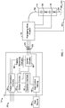
- FIG 2 is a block diagram of an example implementation of the preheating wire feeder 16 of Figure 1 .
- the example preheating wire feeder 16 receives welding-type power as an input, and converts the welding-type power to welding-type power and/or preheating power.
- the preheating wire feeder 16 may output welding-type power and preheating power simultaneously, alternate outputting the welding-type power and the preheating power, and/or output only one of welding-type power or preheating power at a given time, based on the welding task and/or operator experience.
- the preheating wire feeder 16 receives the input power from the welding power source 12 of FIG. 1 via input terminals 40 coupled to control circuitry 56.
- the preheating wire feeder 16 may be operated remotely from the welding power source 12 with relatively long power cables coupling the preheating wire feeder 16 to the welding power source 12.
- the control circuitry 56 includes one or more controller(s) and/or processor(s) 82 that controls the operations of the preheating wire feeder 16.
- the control circuitry 56 receives and processes multiple inputs associated with the performance and demands of the system.
- the processor(s) 82 may include one or more microprocessors, such as one or more "general-purpose" microprocessors, one or more special-purpose microprocessors and/or ASICS, one or more microcontrollers, and/or any other type of processing and/or logic device.
- the control circuitry 56 may include one or more digital signal processors (DSPs).
- the control circuitry 56 may include circuitry such as relay circuitry, voltage and current sensing circuitry, power storage circuitry, and/or other circuitry, and is configured to sense the input power received by the preheating wire feeder 16.
- the example control circuitry 56 includes one or more memory device(s) 84.
- the memory device(s) 84 may include volatile and/or nonvolatile memory and/or storage devices, such as random access memory (RAM), read only memory (ROM), flash memory, hard drives, solid state storage, and/or any other suitable optical, magnetic, and/or solid-state storage mediums.
- RAM random access memory
- ROM read only memory
- flash memory hard drives
- solid state storage and/or any other suitable optical, magnetic, and/or solid-state storage mediums.
- the memory device(s) 84 store data (e.g., data corresponding to a welding application), instructions (e.g., software or firmware to perform welding processes), and/or any other appropriate data. Examples of stored data for a welding application include an attitude (e.g., orientation) of a welding torch, a distance between the contact tip and a workpiece, a voltage, a current, welding device settings, and so forth.
- attitude e.g., orientation
- the memory device 84 may store machine executable instructions (e.g., firmware or software) for execution by the processor(s) 82. Additionally or alternatively, one or more control schemes for various welding processes, along with associated settings and parameters, may be stored in the memory device(s) 84, along with machine executable instructions configured to provide a specific output (e.g., initiate wire feed, enable gas flow, capture welding current data, detect short circuit parameters, determine amount of spatter) during operation.
- a specific output e.g., initiate wire feed, enable gas flow, capture welding current data, detect short circuit parameters, determine amount of spatter
- the preheating wire feeder 16 further includes power conversion circuitry 58.
- the power conversion circuitry 58 is configured to convert a first portion of the input welding-type power to second welding-type power and convert a second portion of the input welding-type power to preheating power.
- the first and second portions of the input welding-type power may be divided by time (e.g., the first portion is used at a first time and the second portion is used at a second time) and/or as portions of the total delivered power at a given time.
- the power conversion circuitry 58 outputs the second welding-type power to a weld circuit, and outputs the preheating power to a preheating circuit. Both the weld circuit and the preheating circuit may be implemented using the welding torch 14.
- the power conversion circuitry 58 may include circuit elements such as boost converters, buck converters, half-bridge converters, full-bridge converters, forward converters, flyback converters, an internal bus, bus capacitor, voltage and current sensors, and/or any other topologies and/or circuitry to convert the input power to the welding power and the preheating power, and to output the welding power and the preheating power to the torch 14.
- input power received by the preheating wire feeder 16 is a DC voltage between approximately 20V to 120V, approximately 40V to 100V, or approximately 60V to 80V. As used in reference to the input power, the term approximately may mean within 5 volts or within 10 percent of the desired voltage.
- the power conversion circuitry 58 may be configured to convert the input power to any conventional and/or future welding-type output.
- the example power conversion circuitry 58 may implement one or more controlled voltage control loop(s) and/or one or more controlled current control loop(s) to control the voltage and/or current output to the welding circuit and/or to the preheating circuit.
- the power conversion circuitry 58 may be implemented using one or more converter circuits, such as multiple converter circuits in which each of the welding-type output and the preheating output is produced using separate ones of the converter circuits.
- the power conversion circuitry 58 is configured to convert the input power to a controlled waveform welding output, such as a pulsed welding process or a short circuit welding process (e.g., regulated metal deposition (RMDTM)).
- a controlled waveform welding output such as a pulsed welding process or a short circuit welding process (e.g., regulated metal deposition (RMDTM)).
- the power conversion circuitry 58 disposed within the preheating wire feeder 16 supplies the controlled waveform welding output for the welding application without attenuation from the power cable between the welding power source and the preheating wire feeder 16. This increases the response time and accuracy of the controlled waveform welding output supplied to the welding torch. Increasing the response time of the controlled waveform welding output may ensure that the desired welding output waveform is supplied to welding torch at specific times during the weld.
- the RMDTM welding process utilizes a controlled waveform welding output having a current waveform that varies at specific points in time over a short circuit cycle. Increasing the response time of the controlled waveform welding output may also improve the timing of the waveform pulses to produce a desired weld.
- the power conversion circuitry 58 is configured to provide the welding output to the wire feed assembly 60.
- the wire feed assembly 60 supplies welding wire 54 to the welding torch for the welding operation.
- the wire feed assembly 60 includes elements such as a wire spool 64 and a wire feed drive configured to power drive rolls 68.
- the wire feed assembly 60 feeds welding wire 54 to the welding torch along a weld cable 62.
- the welding output may be supplied through the weld cable 62 coupled to the welding torch and/or the work cable 42 coupled to the workpiece 44.
- the example preheating wire feeder 16 includes a user interface 66 for control of parameters of the welding system 10.
- the user interface 66 is coupled to the control circuitry 56 for operator selection and adjustment of the welding process (e.g., pulsed, short-circuit, FCAW) through selection of the wire size, wire type, material, and gas parameters.
- the user interface 66 is coupled to the control circuitry 56 for control of the voltage, amperage, wire feed speed, and arc length for a welding application.
- the user interface 66 may receive inputs using any input device, such as via a keypad, keyboard, buttons, touch screen, voice activation system, wireless device, etc.
- the user interface 66 may receive inputs specifying wire material (e.g., steel, aluminum), wire type (e.g., solid, cored), wire diameter, gas type, and/or any other parameters.
- the control circuitry 56 determines the welding output for the welding application. For example, the control circuitry 56 may determine weld voltage, weld current, wire feed speed, inductance, weld pulse width, relative pulse amplitude, wave shape, preheating voltage, preheating current, preheating pulse, preheating resistance, preheating energy input, and/or any other welding and/or preheating parameters for a welding process based at least in part on the input received through the user interface 66.
- the example preheating wire feeder 16 further includes communications circuitry 70 coupled to the control circuitry 56 to send and receive command and/or feedback signals over the power cable used to provide the input power to the preheating wire feeder.
- the communications circuitry 70 may further enable the user interface 66 to control the welding power source.
- the user interface 66 may be configured to control the amperage, voltage, or other parameters of the input power supplied by the welding power source 12.
- the control circuitry 56 controls the welding power source 12 from a location remote from the welding power source 12, without being restricted to parameters set on the operator interface 34 ( FIG. 1 ). That is, the control circuitry 56 and communications circuitry 70 enable an operator to control the welding power source 12 remotely through the preheating wire feeder 16 with equal control priority to the operator interface 34 of the welding power source.
- the communications circuitry 70 may communicate data to other devices in the system 10 of Figure 1 via wireless connections. Additionally or alternatively, the communications circuitry 70 communicates with other welding devices using one or more wired connections, such as by using a network interface controller (NIC) to communicate data via a network (e.g., ETHERNET, 10baseT, 10base100, etc.), and/or communications via the terminals 40 through which the welding-type input power is received.
- NIC network interface controller
- Example implementations of the communications circuitry 70 are described in U.S. Patent No. 9,012,807 . The entirety of U.S. Patent No. 9,012,807 is incorporated herein by reference. However, other implementations of the communications circuitry 70 may be used.
- a valve assembly 72 is included for providing gas to the welding torch 14 along a gas line 74.
- the valve assembly 72 may be controlled by the control circuitry 56.
- the valve assembly 72 may be configured to supply gas to the welding torch 14 prior to and after a welding task.
- the valve assembly 72 is configured to purge the gas line 74 upon receiving a purge command from the user interface 66.
- the power conversion circuitry 58 establishes a welding circuit to conduct welding current from the power conversion circuitry 58 to the first contact tip 18, and returns to the power conversion circuitry 58 via the welding arc 26, the workpiece 44, and the work cable 42.
- the power conversion circuitry 58 establishes a preheating circuit to conduct preheating current through a section 102 of the electrode wire 54.
- the preheating current flows from the power conversion circuitry 58 to the second contact tip 20 via a first cable 106, through the section 102 of the electrode wire 54 to the first contact tip 18, and returns to the power conversion circuitry 58 via a second cable 104 connecting the power conversion circuitry 58 to the first contact tip 18.
- the cables 104, 106 may be combined with other cables and/or conduits.
- the cable 104 and/or the cable 106 may be part of the cable 62.
- the cable 106 is included within the cable 62, and the cable 104 is routed separately to the torch 14.
- the preheating wire feeder 16 may include between one and three terminals to which one or more cables can be physically connected to establish the preheating, welding, and work connections. For example, multiple connections can be implemented into a single terminal using appropriate insulation between different connections.
- the cable 104 may enable a more cost-effective single connection between the first contact tip 18 and the power conversion circuitry 58 (e.g., a single cable) than providing separate connections for the welding current to the first contact tip 18 and for the preheating current to the first contact tip 18.
- the example preheating wire feeder 16 includes a housing 86, within which the control circuitry 56, the power conversion circuitry 58, the wire feed assembly 60, the user interface 66, the communications circuitry 70, and/or the valve assembly 72 are enclosed.
- the power conversion circuitry 58 includes multiple power conversion circuits (e.g., a preheating power conversion circuit and a welding power conversion circuit), all of the power conversion
- Figure 3a is a block diagram of example power conversion circuitry 300 that may be used to implement the power conversion circuitry 58 of Figure 2 to convert input welding-type power to output welding-type power and preheating power.
- the example power conversion circuitry 300 of Figure 3a includes preheat power conversion circuitry 302 and weld power conversion circuitry 304.
- the preheat power conversion circuitry 302 and weld power conversion circuitry 304 are both coupled to an input to receive respective portions of the welding-type input power 306 (e.g., from the power source 12, via the terminals 40 of Figure 2 ).
- Each of the example preheat power conversion circuitry 302 and the weld power conversion circuitry 304 includes respective conversion circuitry.
- the preheat power conversion circuitry 302 includes a boost converter circuit 308a, a bus capacitor 310a, and a buck converter circuit 312a.
- the weld power conversion circuitry 304 includes a boost converter circuit 308b, a bus capacitor 310b, and a buck converter circuit 312b.
- the boost converter circuits 308a, 308b are each configured to convert the input welding-type power 306 to respective bus voltages that are output to the respective buck converters 312a, 312b.
- the example buck converters 312a, 312b convert the bus voltage to a desired output.
- the buck converter 312a converts the bus voltage output by the boost converter 310a to a preheating output 314, having a preheating output voltage and/or a preheating output current.
- the buck converter 312b converts the bus voltage output by the boost converter 308b to a weld output 316, having a welding output voltage and/or a welding output current
- the bus capacitors 310a, 310b store energy to reduce bus voltage ripple due to changes in power output by the buck converters 312a, 312b.
- the example control circuitry 56 of Figure 2 controls the boost converters 308a, 308b and the buck converters 312a, 312b, according to the input welding-type current and the desired preheating output and the desired welding output.
- the control circuitry 56 may control one or both of the preheat power conversion circuitry 302 and the weld power conversion circuitry 304 to be off at a given time.
- control circuitry 56 may control the weld power conversion circuitry 304 to output welding-type current for a first welding operation, or a first portion of a welding operation, and then control both of the preheat power conversion circuitry 302 and the weld power conversion circuitry 304 to perform a second welding operation, or a second portion of a welding operation, using both welding a preheating power.
- control circuitry 56 is configured to adjust control of the weld power conversion circuitry to adjust the welding output 316 based on the preheating output, such as to maintain a consistent heat input to the weld and/or increase deposition.
- control circuitry 56 may decrease the weld output 316 (e.g., weld voltage and/or the weld current) via the weld power conversion circuitry 304 based on controlling the preheat power conversion circuitry 302 to increase in the preheat output 314.
- Figure 3b is a block diagram of example power conversion circuitry 320 that may be used to implement the power conversion circuitry 58 of Figure 2 to convert input welding-type power to output the welding-type output 316 and the preheating output 314.
- the example power conversion circuitry 320 of Figure 3b includes preheat power conversion circuitry 322 and weld power conversion circuitry 324.
- the preheat power conversion circuitry 322 and weld power conversion circuitry 324 receive a bus voltage from a shared boost converter 308 instead of receiving the welding-type input power 306 as an input.
- the preheat power conversion circuitry 322 and weld power conversion circuitry 324 are both coupled to a bus voltage that is output by the boost converter 308, which converts the welding-type input power 306 to the bus voltage.
- the bus capacitor(s) 310 are also shared between the preheat power conversion circuitry 322 and weld power conversion circuitry 324, although each of the preheat power conversion circuitry 322 and weld power conversion circuitry 324 may have respective bus capacitors 310.
- the example buck converters 312a, 312b convert the bus voltage to a desired output.
- the example control circuitry 56 of Figure 2 controls the boost converter 308 and the buck converters 312a, 312b to output the preheating output 314 and/or the welding output 316.
- welding pendants may be configured to include the power conversion circuitry disclosed herein to provide welding power and preheating power based on input welding-type power, and used in conjunction with a conventional wire feeder to provide welding and preheating power to a welding torch.
- the disclosed examples may also be used in conjunction with other forms of wire heating, such as inductive heating of the wire, hotwire techniques, arc-based preheating in which an electrical arc is used to apply heat to the wire prior to the welding arc, laser-based preheating, radiant heating, convective heating, and/or any other forms of wire heating.
- Figure 4 is a flowchart representative of example machine readable instructions 400 which may be executed by control circuitry of the example preheating wire feeder 16 of Figure 1 , or another welding accessory, to convert welding-type power to welding-type power and preheating power.
- the example instructions 400 are described below with reference to the preheating wire feeder 16 of Figure 2 , and the example power conversion circuitry 300 of Figure 3a . However, the instructions 400 may be executed using other implementations of the preheating wire feeder 16, the power conversion circuitry 58, and/or other welding accessories.
- the control circuitry 56 determines whether an input specifying welding process parameter(s) has been received. For example, the control circuitry 56 may receive input(s) specifying any one or more of the welding process parameter comprises at least one of a workpiece thickness, a workpiece material, a wire material, a wire type, a wire diameter, a gas type, or a total heat input limit. Additionally or alternatively, the control circuitry 32 may receive welding parameters (e.g., welding voltage, welding current, wire feed speed, pulse parameters, welding gas flow, etc.), preheating parameters (e.g., preheating voltage, preheating current, preheating temperature, preheating resistance, preheating heat input), total heat input, and/or any other parameters as inputs. The control circuitry 56 may receive the inputs via the user interface 66 and/or via the communications circuitry 70 of Figure 2 .
- welding parameters e.g., welding voltage, welding current, wire feed speed, pulse parameters, welding gas flow, etc.
- preheating parameters e.g., pre
- the control circuitry 56 determines a welding power output and/or a preheating power output based on the received welding process parameters. For example, the control circuitry 32 may determine one or more of a weld voltage, a weld current, a wire feed speed, an inductance, a weld pulse width, a relative pulse amplitude, a wave shape, a preheating voltage, a preheating current, a preheating pulse, a preheating resistance, a preheating energy input, and/or any other welding power parameter and/or preheating power parameter.
- the control circuitry 56 determines whether welding is active. For example, the control circuitry 56 may determine whether a trigger is depressed on the welding torch 14 and/or whether welding-type power is available at an input to the power conversion circuitry 58. If welding is not active (block 406), control returns to block 402 to await an input.
- the power conversion circuitry 58 receives the welding-type power input (e.g., from the power source 12 of Figure 1 , via the terminals 40).
- the control circuitry 56 determines whether a welding output is enabled (e.g., based on the welding process parameters). If the welding output is enabled (block 410), at block 412 the power conversion circuitry 58 converts at least a portion of the welding-type power input to a welding-type power output based on the determined welding power output.
- the control circuitry 56 may control the weld power conversion circuitry 304, the boost converter 308b, and/or the buck converter 312b of Figure 3a , to convert the input power 306 to the welding output 316.
- the power conversion circuitry 58 outputs the welding-type power to the weld torch 14.
- the weld output 316 is conducted to the contact tip 18 and the work cable 42 for generation of the arc 26.
- the control circuitry 56 determines whether preheating is enabled (e.g., based on the welding process parameters). For example, the control circuitry 56 may selectively enable the preheat power conversion circuitry 302 to provide the preheating output 314 and to selectively disable the second power conversion circuitry 302 to stop the preheating output 314. The control circuitry 56 may enable and/or disable the preheating based on, for example, a user input via the user interface 66, and/or an input from the power source, a remote control, and/or the welding torch 14, via the communications circuitry 70.
- the power conversion circuitry 58 converts at least a portion of the welding-type power input to a preheating power output based on the determined preheating power output.
- the control circuitry 56 may control the preheat power conversion circuitry 302, the boost converter 308a, and/or the buck converter 312a of Figure 3a , to convert the input power 306 to the preheating output 314.
- the power conversion circuitry 58 outputs the welding-type power to the weld torch 14.
- the preheating output 314 is conducted to the contact tip 18 and the contact tip 20 via the cables 104, 106.
- control After outputting the preheating power (block 420), or if the preheating is disabled (block 416), control returns to block 406 to determine whether welding is still active.
- FIG. 5 illustrates another example welding system 500 configured to transfer welding-type power to a welding accessory, such as the preheating wire feeder 16, for conversion to welding-type output power and resistive preheating power, in accordance with aspects of this disclosure.
- the example system 500 of Figure 5 is similar to the example welding system 10 of Figure 1 , in that the power source 12 provides welding-type power to the preheating wire feeder 16, which converts at least a portion of the welding-type power to preheating power for output to the welding torch 14.
- the example preheating wire feeder 16 is coupled to the power source 12 via one conductor (e.g., via a positive or negative connection) in a manner similar to a conventional voltage sensing wire feeder.
- the power source 12 is coupled to the workpiece 44 via a work cable 502 to enable the completion of the weld circuit.
- the preheating wire feeder is also coupled to the workpiece 44 via a voltage sense lead 504. Because the voltage sense lead 504 is not part of the weld circuit and does not conduct weld current, the voltage sense lead 504 may be designed to conduct less current than the work cables 42, 502. However, the voltage sense lead 504 is configured to withstand sufficient current to provide power to preheating power conversion circuitry, communications circuitry, control circuitry, and/or wire feeding hardware.
- the example preheating wire feeder 16 converts at least a portion of the power received from the power source 12 to preheating power.
- the preheating wire feeder 16 outputs the preheating power to the first and second contact tips 18, 20 via conductors 506, 508, and is further configured to pass welding-type power through to the first contact tip 18 to generate the welding arc 26 via the conductor 508 and/or a separate conductor and/or cable.
- One or more of the conductors 506, 508 carrying preheating and/or welding current may be combined into a cable with the wire liner conducting the welding wire 54, and/or with a gas line conducting shielding gas to the welding torch 14.
- the voltage sense lead 504 may have any other purpose (e.g., providing power to drive the wire feed assembly 60, the control circuitry 56, and/or the communications circuitry), or no other purpose other than to couple the power conversion circuitry 302 to the workpiece 44 to close a power supply circuit to the power source 12.
- Such conductors or leads may be conventionally referred to as voltage sense leads, or the like, in relevant fields of use.
- Other example conductors that may be used include a conventional control cable that couples the wire feeder 16 to the power source 12 (e.g., via a 14-pin connector on the power source 12).
- FIG 6 is a block diagram of another example preheating wire feeder 600 that may be used to implement the preheating wire feeder 16 of Figure 5 .
- the example preheating wire feeder 600 includes the control circuitry 56, the wire feed assembly 60, the user interface 66, the communications circuitry 70, and the valve assembly 72 of Figure 2 . However, one or more of those components may be omitted, replaced, and/or otherwise modified from the examples disclosed herein.
- the example preheating wire feeder 600 is configured to receive welding-type power as an input from the power source 12 via a terminal 40. The welding-type power is passed through to the first contact tip 18 of the welding torch 14.
- the preheating wire feeder 600 includes a contactor configured to connect and disconnect the welding-type power input from the welding-type power output.
- the control circuitry 56 may control a contactor to connect or disconnect the input from the output based on whether welding-type power and/or wire feeding is to be performed.
- the preheating wire feeder 600 includes a voltage sensor 602 configured to measure a voltage across the welding arc 26 during welding, which can provide a more accurate weld voltage feedback for arc control purposes.
- the preheating wire feeder 600 is coupled to the welding-type output, and is connected to the workpiece 42 via the voltage sense lead 504.
- the example preheating wire feeder 600 includes the example preheat power conversion circuitry 302 of Figure 3a , but may include other types of preheat power conversion circuitry as disclosed herein.
- the preheat power conversion circuitry 600 is coupled to the welding-type input to receive at least a portion of the welding-type input power.
- the example preheat power conversion circuitry 302 is further coupled to the voltage sense lead 504, which is coupled to the power source 12 via the workpiece 44 and the work cable 502 of Figure 5 .
- the example preheating power conversion circuitry 302 converts the input welding-type power (e.g., DC power) to preheating power 314, which is output to the contact tips 18, 20 in the welding torch 14.
- preheating power 314 e.g., DC power
- FIG 7 is a block diagram of another example preheating wire feeder 700 that may be used to implement the preheating wire feeder 16 of Figure 1 .
- the example preheating wire feeder 700 includes the terminals 40, the control circuitry 56, the wire feed assembly 60, the power conversion circuitry 58, the user interface 66, the communications circuitry 70, and the valve assembly 72 of Figure 2 . However, one or more of those components may be omitted, replaced, and/or otherwise modified from the examples disclosed herein.
- the preheating wire feeder 700 is configured to output welding-type power and providing preheating power to a welding wire 54 via a welding torch 14 having only the first contact tip 18 within a body of the housing (e.g., the portion of the welding torch 14 that is held and/or manipulated during a welding operation to position and/or direct the arc 26).
- the example power conversion circuitry 58 is coupled to the wire feed assembly 60 for delivery of the preheating output 314 to the welding wire 54.
- the power conversion circuitry 58 supplies the preheating output 314 to the welding wire 54 between the contact tip 18 and the wire feed assembly 60 (e.g., via conductive rollers in the wire feed assembly 60, and/or via a contact element in the preheating wire feeder).
- the power conversion circuitry 58 may provide a relatively low preheat current due to the time required for the welding wire 54 to traverse the distance from the power conversion circuitry 58 (or contact element) in the wire feeder 600 and the contact tip 18, to avoid melting the welding wire 54 or causing buckling due to reduction in column strength of the welding wire 54.
- the example wire feeder 600 of Figure 6 may be similarly configured, such that the preheat power conversion circuitry 302 outputs the preheating output 314 via the wire feed assembly 60 when using a welding torch 14 having a single contact tip 14.
- the example wire feeder 700 of Figure 7 further increases the hydrogen that is removed from the welding wire 54 prior to reaching the welding arc 26.
- the use of a welding torch 14 having a single contact tip 14 reduces the weight and size of the welding torch 14 relative to a torch using multiple contact tips.
- FIG 8 is a block diagram of another example preheating wire feeder 800 that may be used to implement the preheating wire feeder 16 of Figure 1 .
- the example preheating wire feeder 800 includes the terminals 40, the control circuitry 56, the wire feed assembly 60, the power conversion circuitry 58, the user interface 66, the communications circuitry 70, and the valve assembly 72 of Figure 2 . However, one or more of those components may be omitted, replaced, and/or otherwise modified from the examples disclosed herein.
- the power conversion circuitry 58 outputs the preheating output 314 to a wire preheater 802 within the housing 86, such as within the wire feed assembly 60.
- the example wire preheater 802 may provide any of resistive preheating (e.g., via two contact points on the welding wire 54), inductive heating of the welding wire 54 (e.g., via routing the welding wire 54 through or near an induction coil), arc-based preheating (e.g., via one or more tungsten electrodes configured to establish an electrical arc to the welding wire 54), laser-based preheating (e.g., via a laser configured to output energy to the welding wire 54), radiant heating (e.g., via heating coils not in contact with the welding wire 54 but configured to heat the welding wire 54 via radiation), convective heating (e.g., via heating coils, ceramic, or other heated material configured to contact the welding wire 54 to transfer heat to the welding wire 54), and/or any other preheating technique.
- resistive preheating e
- a standard welding torch may be used by the operator, rather than a torch that includes preheating and/or liquid-cooling apparatus.
- performing preheating at the preheating wire feeder 800 may reduce bulk of the torch to be held and manipulated by the operator.
- any of the other preheating wire feeders disclosed herein may be modified to include the wire preheater 802.
- Figure 9 is a block diagram of an example preheating wire feeder 900 that may be used to implement the preheating wire feeder 16 of Figure 1 to provide preheating power to a wire preheater 902 in the torch 14.
- the power conversion circuitry 58 outputs the preheating output 314 to the wire preheater 902 within the torch 14.
- the example wire preheater 902 may provide any of inductive heating of the welding wire 54 (e.g., via routing the welding wire 54 through or near an induction coil), arc-based preheating (e.g., via one or more tungsten electrodes configured to establish an electrical arc to the welding wire 54), laser-based preheating, radiant heating, convective heating, and/or any other preheating technique.
- the example preheating wire feeder 900 preheats the welding wire 54 via the wire preheater 902.
- the example control circuitry 56 may control the power conversion circuitry 58 as described above with reference to Figure 4 .
- the wire preheater 902 may be located in (e.g., integrated with or attached to) the cable whip attaching the torch 14 to the wire feeder 16.
- the cable may be provided with a housing partway along the cable whip, far enough away from the torch body (e.g., the handheld portion of the torch 14) so that the mass of the wire preheater 902 does not substantially affect the manipulation of the torch 14 by the operator during welding operations.
- the present devices and/or methods may be realized in hardware, software, or a combination of hardware and software.
- the present methods and/or systems may be realized in a centralized fashion in at least one computing system, processors, and/or other logic circuits, or in a distributed fashion where different elements are spread across several interconnected computing systems, processors, and/or other logic circuits. Any kind of computing system or other apparatus adapted for carrying out the methods described herein is suited.
- a typical combination of hardware and software may be a processing system integrated into a welding power supply with a program or other code that, when being loaded and executed, controls the welding power supply such that it carries out the methods described herein.
- Another typical implementation may comprise an application specific integrated circuit or chip such as field programmable gate arrays (FPGAs), a programmable logic device (PLD) or complex programmable logic device (CPLD), and/or a system-on-a-chip (SoC).
- FPGAs field programmable gate arrays
- PLD programmable logic device
- CPLD complex programmable logic device
- SoC system-on-a-chip
- Some implementations may comprise a non-transitory machine-readable (e.g., computer readable) medium (e.g., FLASH memory, optical disk, magnetic storage disk, or the like) having stored thereon one or more lines of code executable by a machine, thereby causing the machine to perform processes as described herein.
- non-transitory machine readable medium is defined to include all types of machine readable storage media and to exclude propagating signals.
- An example control circuit implementation may be a microcontroller, a field programmable logic circuit and/or any other control or logic circuit capable of executing instructions that executes weld control software.
- the control circuit could also be implemented in analog circuits and/or a combination of digital and analog circuitry.
Landscapes
- Engineering & Computer Science (AREA)
- Physics & Mathematics (AREA)
- Plasma & Fusion (AREA)
- Mechanical Engineering (AREA)
- Arc Welding Control (AREA)
- Arc Welding In General (AREA)
Abstract
Description
- This patent claims the benefit of
U.S. Provisional Patent Application Serial No. 62/826,320, filed March 29, 2019 U.S. Patent Application Serial No. 62/826,320 - This disclosure relates generally to welding and, more particularly, to methods and apparatus to convert welding-type power to welding-type power and resistive preheating power.
- Welding is a process that has increasingly become ubiquitous in all industries. Welding is, at its core, simply a way of bonding two pieces of metal. A wide range of welding systems and welding control regimes have been implemented for various purposes. In continuous welding operations, metal inert gas (MIG) welding and submerged arc welding (SAW) techniques allow for formation of a continuing weld bead by feeding welding wire shielded by inert gas from a welding torch and/or by flux. Such wire feeding systems are available for other welding systems, such as tungsten inert gas (TIG) welding. Electrical power is applied to the welding wire and a circuit is completed through the workpiece to sustain a welding arc that melts the electrode wire and the workpiece to form the desired weld.
- Methods and apparatus to convert welding-type power to welding-type power and resistive preheating power are disclosed, substantially as illustrated by and described in connection with at least one of the figures, as set forth more completely in the claims.
-
-
Figure 1 illustrates an example welding system configured to transfer welding-type power to a welding accessory, such as a preheating wire feeder, for conversion to welding-type output power and resistive preheating power, in accordance with aspects of this disclosure. -
Figure 2 is a block diagram of an example implementation of the preheating wire feeder ofFigure 1 . -
Figure 3a is a block diagram of an example implementation of the power conversion circuitry ofFigure 2 . -
Figure 3b is a block diagram of another example implementation of the power conversion circuitry ofFigure 2 . -
Figure 4 is a flowchart representative of example machine readable instructions which may be executed by the example welding accessory ofFigures 1 orFigure 2 to convert welding-type power to welding-type power and preheating power. -
Figure 5 illustrates another example welding system configured to transfer welding-type power to a welding accessory, such as the preheating wire feeder, for conversion to welding-type output power and resistive preheating power, in accordance with aspects of this disclosure. -
Figure 6 is a block diagram of another example preheating wire feeder that may be used to implement the preheating wire feeder ofFigure 5 . -
Figure 7 is a block diagram of another example preheating wire feeder that may be used to implement the preheating wire feeder ofFigure 1 . -
Figure 8 is a block diagram of another example preheating wire feeder that may be used to implement the preheating wire feeder ofFigure 1 . -
Figure 9 is a block diagram of another example preheating wire feeder that may be used to implement the preheating wire feeder ofFigure 1 . - The figures are not necessarily to scale. Where appropriate, similar or identical reference numbers are used to refer to similar or identical components.
- For the purpose of promoting an understanding of the principles of this disclosure, reference will be now made to the examples illustrated in the drawings and specific language will be used to describe the same. It will nevertheless be understood that no limitation of the scope of the claims is intended by this disclosure. Modifications in the illustrated examples and such further applications of the principles of this disclosure as illustrated therein are contemplated as would typically occur to one skilled in the art to which this disclosure relates.
- As used herein, the word "exemplary" means "serving as an example, instance, or illustration." The embodiments described herein are not limiting, but rather are exemplary only. It should be understood that the described embodiments are not necessarily to be construed as preferred or advantageous over other embodiments. Moreover, the terms "embodiments of the invention," "embodiments," or "invention" do not require that all embodiments of the invention include the discussed feature, advantage, or mode of operation.
- As utilized herein the terms "circuits" and "circuitry" refer to physical electronic components (i.e. hardware) and any software and/or firmware (code) that may configure the hardware, be executed by the hardware, and/or otherwise be associated with the hardware. As used herein, for example, a particular processor and memory may comprise a first "circuit" when executing a first set of one or more lines of code and may comprise a second "circuit" when executing a second set of one or more lines of code. As utilized herein, "and/or" means any one or more of the items in the list joined by "and/or". As an example, "x and/or y" means any element of the three-element set {(x), (y), (x, y)}. In other words, "x and/or y" means "one or both of x and y." As another example, "x, y, and/or z" means any element of the seven-element set {(x), (y), (z), (x, y), (x, z), (y, z), (x, y, z)}. In other words, "x, y, and/or z" means "one or more of x, y and z". As utilized herein, the term "exemplary" means serving as a non-limiting example, instance, or illustration. As utilized herein, the terms "e.g." and "for example" set off lists of one or more non-limiting examples, instances, or illustrations. As utilized herein, circuitry is "operable" to perform a function whenever the circuitry comprises the necessary hardware and code (if any is necessary) to perform the function, regardless of whether performance of the function is disabled or not enabled (e.g., by an operator-configurable setting, factory trim, etc.).
- As used herein, a wire-fed welding-type system refers to a system capable of performing welding (e.g., gas metal arc welding (GMAW), gas tungsten arc welding (GTAW), submerged arc welding (SAW), etc.), brazing, cladding, hardfacing, and/or other processes, in which a filler metal is provided by a wire that is fed to a work location, such as an arc or weld puddle.
- As used herein, a welding-type power source refers to any device capable of, when power is applied thereto, supplying welding, cladding, plasma cutting, induction heating, laser (including laser welding and laser cladding), carbon arc cutting or gouging and/or resistive preheating, including but not limited to transformer-rectifiers, inverters, converters, resonant power supplies, quasi-resonant power supplies, switch-mode power supplies, etc., as well as control circuitry and other ancillary circuitry associated therewith.
- As used herein, preheating refers to heating the electrode wire prior to a welding arc and/or deposition in the travel path of the electrode wire.
- Some disclosed examples describe electric currents being conducted "from" and/or "to" locations in circuits and/or power supplies. Similarly, some disclosed examples describe "providing" electric current via one or more paths, which may include one or more conductive or partially conductive elements. The terms "from," "to," and "providing," as used to describe conduction of electric current, do not necessitate the direction or polarity of the current. Instead, these electric currents may be conducted in either direction or have either polarity for a given circuit, even if an example current polarity or direction is provided or illustrated.
- Systems and methods to provide preheating power and welding power to a welding torch are disclosed herein. In particular, disclosed example systems include a welding-type power source configured to output welding-type power to a welding accessory, such as a wire feeder. The accessory includes one or more power conversion circuits to convert a portion of the input welding-type power to output welding-type power and another portion of the input welding-type power to preheating power.
- In an example application, a preheating-enabled wire feeder may be selected by a weld operator and coupled to the output of a generic welding power source. The weld operator does not necessarily need to know the location of the welding power source, because the preheating-enabled wire feeder converts the power supplied by the welding power source to the welding and/or preheating power, which may be specified by the operator at the wire feeder. In some examples, the wire feeder may communicate appropriate configuration information to the connected power source to supply the power for a given welding task involving welding power and/or preheating power. Thus, disclosed example systems and methods may eliminate the need for multiple welding power sources to provide both welding and preheating power.
- Disclosed example welding accessories include: a weld input configured to receive first welding-type power; and power conversion circuitry configured to: convert a first portion of the first welding-type power to second welding-type power; and output the second welding-type power to a weld circuit; convert a second portion of the first welding-type power to preheating power; and output the preheating power to a preheater.
- In some examples, the power conversion circuitry includes first power conversion circuitry configured to convert the first portion of the first welding-type power to the second welding-type power, and second power conversion circuitry configured to convert the second portion of the first welding-type power to the preheating power. In some examples, the welding accessory includes a housing configured to enclose the first power conversion circuitry and the second power conversion circuitry. In some examples, the first power conversion circuitry and the second power conversion circuitry are configured to be electrically coupled to the welding torch via a same cable. In some example welding accessories, the first power conversion circuitry comprises a first switched-mode power supply and the second power conversion circuitry comprises a second switched-mode power supply.
- Some example welding accessories further include control circuitry configured to selectively enable the power conversion circuitry to provide the preheating power and to selectively disable the power conversion circuitry to stop the preheating power. In some examples, the control circuitry is configured to selectively enable or disable the power conversion circuitry based on a user input. Some examples further include communications circuitry configured to receive the user input from at least one of a weld torch coupled to the wire feeder or a pendant. Some examples further include a user interface configured to receive a user input, in which the control circuitry is configured to control the power conversion circuitry based on the user input.
- Some example welding accessories include control circuitry configured to control electrical parameters of the power conversion circuitry based on the preheating power applied to the electrode wire. Some example welding accessories include control circuitry configured to control the power conversion circuitry using a voltage-controlled control loop. Some example welding accessories include communication circuitry configured to communicate with a welding-type power supply from which the weld input receives the first welding-type power. In some examples, the control circuitry is configured to transmit electrical parameters to the welding-type power supply based on at least one of the second welding-type power or the preheating power.
- In some examples, the weld input includes one terminal configured to be coupled to a weld cable, in which the power conversion circuitry is configured to output the second welding-type power to the weld circuit via one output and to be coupled to a workpiece via a volt sense cable. In some examples, the weld input includes two or more terminals coupled to two or more cables to receive the first welding-type power, wherein the power conversion circuitry is configured to output the second welding-type power to the weld circuit via two or more output terminals. In some examples, the first welding-type power includes direct current power output by a welding-type power supply. Some example welding accessories further include a wire drive configured to feed the electrode wire toward a welding torch. In some examples, the welding accessory is a wire feeder or a pendant.
- In some examples, the preheater includes at least one of: a preheating circuit including a portion of an electrode wire located between a first contact point and a second contact point; an induction coil configured to heat the electrode wire; a tungsten electrode configured to establish an arc to the electrode wire; a laser configured to output energy to the electrode wire; a heating coil configured to heat the electrode wire via radiation; or a convective heating material configured to contact the electrode wire to transfer heat to the electrode wire.
- Disclosed example welding systems include: first power conversion circuitry configured to: convert a first portion of the first welding-type power to second welding-type power; and output the second welding-type power to a weld circuit; second power conversion circuitry configured to: convert a second portion of the first welding-type power to preheating power; and output the preheating power to a preheater; and control circuitry configured to control the first power conversion circuitry and the second power conversion circuitry.
-
Figure 1 illustrates anexample welding system 10 configured to transfer welding-type power to a welding accessory, such as apreheating wire feeder 16, for conversion to welding-type output power and resistive preheating power. Theexample welding system 10 ofFigure 1 includes awelding power source 12 and a preheatingwelding torch 14. Thewelding torch 14 may be a torch configured for any wire-fed welding process, such as gas metal arc welding (GMAW), flux cored arc welding (FCAW), self-shielded FCAW, and/or submerged arc welding (SAW), based on the desired welding application. - The
welding power source 12 supplies welding-type power to thepreheating wire feeder 16, which converts the input welding-type power to one or both of output welding-type power and/or resistive preheating power, which are output to thewelding torch 14. Thepreheating wire feeder 16 also supplies the filler metal to awelding torch 14 configured for GMAW welding, FCAW welding, or SAW welding. - The
welding power source 12 is coupled to, or includes, aprimary power source 22, such as an electrical grid or engine-driven generator that supplies primary power, which may be single-phase or three-phase AC power. For example, thewelding power source 12 may be an engine-driven welding power source that includes the engine and generator that provides theprimary power 22 within the welding power source. Thewelding power source 12 may process the primary power to output welding-type power for output to thewelding torch 14 or thewire feeder 16 viapower cables 24. In some examples, thepower cables 24 includes multiple terminals, in which one terminal has a positive polarity and another terminal has a negative polarity.Power conversion circuitry 30 converts the primary (e.g., AC) current to welding-type power as either direct current (DC) or AC. Thepower conversion circuitry 30 may include circuit elements such as transformers, switches, boost converters, inverters, and so forth, capable of converting power as dictated by the demands of thewelding system 10. In some embodiments, the power conversion circuitry 3 0 is configured to convert the primary power to an approximately 80V DC welding-type power to supply thepreheating wire feeder 16. Such example input power may be between approximately 50 to 120V DC. - The
welding power source 12 includescontrol circuitry 32 and anoperator interface 34. Thecontrol circuitry 32 controls the operations of thewelding power source 12 and may receive input from theoperator interface 34 through which an operator may choose a welding process (e.g., GMAW, FCAW, SAW) and input desired parameters of the input power (e.g., voltages, currents, particular pulsed or non-pulsed welding regimes, and so forth). Thecontrol circuitry 32 may be configured to receive and process a plurality of inputs regarding the performance and demands of thesystem 10. - The
welding power source 12 may includepolarity reversing circuitry 36 andcommunications circuitry 38 coupled to thecontrol circuitry 32. Thepolarity reversing circuitry 36 reverses the polarity of the output welding-type power when directed by thecontrol circuitry 32. For example, some welding processes, such as TIG welding, may enable a desired weld when the electrode has a negative polarity, known as DC electrode negative (DCEN). Other welding processes, such as stick or GMAW welding, may enable a desired weld when the electrode has a positive polarity, known as DC electrode positive (DCEP). When switching between a TIG welding process and a GMAW welding process, thepolarity reversing circuitry 36 may be configured to reverse the polarity from DCEN to DCEP. Additionally or alternatively, the operator may simply connect the terminals of thecable 24 to thepreheating wire feeder 16 without knowledge of the polarity, such as when the terminals are located a substantial distance from thepower source 12. Thecontrol circuitry 32 may direct thepolarity reversing circuitry 36 to reverse the polarity in response to signals received through thecommunications circuitry 38. - In some examples, the
communications circuitry 38 is configured to communicate with thewelding torch 14, thepreheating wire feeder 16, and/or other device(s) coupled to thepower cables 24. Thecommunications circuitry 38 sends and receives command and/or feedback signals over thewelding power cables 24 used to supply the welding-type power. Additionally or alternatively, thecommunications circuitry 38 communicates wirelessly with thewelding torch 14, thepreheating wire feeder 16, and/or other device(s). - For some welding processes (e.g., GMAW), a shielding gas is utilized during welding. In the example of
Figure 1 , thewelding power source 12 includes one or moregas control valves 46 configured to control a gas flow from agas source 48. Thecontrol circuitry 32 controls thegas control valves 46. Thewelding power source 12 may be coupled to one ormultiple gas sources 48 because, for example, some welding processes may utilize different shielding gases than others. In some examples, thewelding power source 12 is configured to supply the gas with the input power via a combined input cable 50 (e.g., including the conductors included in the cable 24). In other examples, thegas control valves 46 andgas source 48 may be separate from thewelding power source 12. For example, thegas control valves 46 may be disposed within thepreheating wire feeder 16, as described below with reference toFigure 2 . - The
preheating wire feeder 16 receives the welding-type power as an input via input terminals configured to couple with the terminals of thepower cables 24. The examplepreheating wire feeder 16 ofFigure 1 is coupled to a preheatingGMAW torch 14 configured to supply the gas,welding wire 54, and electrical power to the welding application. As discussed in more detail below, thepreheating wire feeder 16 is configured to receive input welding-type power from thepower source 12, convert a first portion of the input welding-type power to second welding-type power and output the second welding-type power to a weld circuit, and convert a second portion of the input welding-type power to preheating power and output the preheating power to a preheating circuit. - The
example torch 14 includes afirst contact tip 18 and asecond contact tip 20. Theelectrode wire 54 is fed from thepreheating wire feeder 16 to thetorch 14 and through thecontact tips electrode wire 54 and the workpiece 44. The preheating circuit includes thefirst contact tip 18, thesecond contact tip 20, and a portion of theelectrode wire 54 that is located between thefirst contact tip 18 and asecond contact tip 20. The examplepreheating wire feeder 16 is further coupled to awork cable 42 that is coupled to the workpiece 44. - In operation, the
electrode wire 54 passes through thesecond contact tip 20 and thefirst contact tip 18, between which thepreheating wire feeder 16 outputs a preheating current to heat theelectrode wire 54. Specifically, in the configuration shown inFigure 1 , the preheating current enters theelectrode wire 54 via thesecond contact tip 20 and exits via thefirst contact tip 18. However, the preheating current may be conducted in the opposite direction. At thefirst contact tip 18, a welding current may also enter (or exit) theelectrode wire 54. The welding current is output by thepreheating wire feeder 16, which derives the preheating power and the welding-type power from the welding-type power supplied by thepower source 12. The welding current exits theelectrode wire 54 via the workpiece 44, which in turn generates the welding arc 26. When theelectrode wire 54 makes contact with the workpiece 44, an electrical circuit is completed and the welding current flows through theelectrode wire 54, across the metal work piece(s) 44, and returns to thepreheating wire feeder 16. The welding current causes theelectrode wire 54 and the parent metal of the work piece(s) 44 in contact with theelectrode wire 54 to melt, thereby joining the work pieces as the melt solidifies. By preheating theelectrode wire 54, the welding arc 26 may be generated with drastically reduced arc energy. Generally speaking, the preheating current is proportional to the distance between thecontact tips electrode wire 54 size. -
Figure 2 is a block diagram of an example implementation of thepreheating wire feeder 16 ofFigure 1 . The examplepreheating wire feeder 16 receives welding-type power as an input, and converts the welding-type power to welding-type power and/or preheating power. For example, thepreheating wire feeder 16 may output welding-type power and preheating power simultaneously, alternate outputting the welding-type power and the preheating power, and/or output only one of welding-type power or preheating power at a given time, based on the welding task and/or operator experience. - The
preheating wire feeder 16 receives the input power from thewelding power source 12 ofFIG. 1 viainput terminals 40 coupled to controlcircuitry 56. Thepreheating wire feeder 16 may be operated remotely from thewelding power source 12 with relatively long power cables coupling thepreheating wire feeder 16 to thewelding power source 12. - The
control circuitry 56 includes one or more controller(s) and/or processor(s) 82 that controls the operations of thepreheating wire feeder 16. Thecontrol circuitry 56 receives and processes multiple inputs associated with the performance and demands of the system. The processor(s) 82 may include one or more microprocessors, such as one or more "general-purpose" microprocessors, one or more special-purpose microprocessors and/or ASICS, one or more microcontrollers, and/or any other type of processing and/or logic device. For example, thecontrol circuitry 56 may include one or more digital signal processors (DSPs). Thecontrol circuitry 56 may include circuitry such as relay circuitry, voltage and current sensing circuitry, power storage circuitry, and/or other circuitry, and is configured to sense the input power received by thepreheating wire feeder 16. - The
example control circuitry 56 includes one or more memory device(s) 84. The memory device(s) 84 may include volatile and/or nonvolatile memory and/or storage devices, such as random access memory (RAM), read only memory (ROM), flash memory, hard drives, solid state storage, and/or any other suitable optical, magnetic, and/or solid-state storage mediums. The memory device(s) 84 store data (e.g., data corresponding to a welding application), instructions (e.g., software or firmware to perform welding processes), and/or any other appropriate data. Examples of stored data for a welding application include an attitude (e.g., orientation) of a welding torch, a distance between the contact tip and a workpiece, a voltage, a current, welding device settings, and so forth. Thememory device 84 may store machine executable instructions (e.g., firmware or software) for execution by the processor(s) 82. Additionally or alternatively, one or more control schemes for various welding processes, along with associated settings and parameters, may be stored in the memory device(s) 84, along with machine executable instructions configured to provide a specific output (e.g., initiate wire feed, enable gas flow, capture welding current data, detect short circuit parameters, determine amount of spatter) during operation. - The
preheating wire feeder 16 further includespower conversion circuitry 58. Thepower conversion circuitry 58 is configured to convert a first portion of the input welding-type power to second welding-type power and convert a second portion of the input welding-type power to preheating power. The first and second portions of the input welding-type power may be divided by time (e.g., the first portion is used at a first time and the second portion is used at a second time) and/or as portions of the total delivered power at a given time. Thepower conversion circuitry 58 outputs the second welding-type power to a weld circuit, and outputs the preheating power to a preheating circuit. Both the weld circuit and the preheating circuit may be implemented using thewelding torch 14. - The
power conversion circuitry 58 may include circuit elements such as boost converters, buck converters, half-bridge converters, full-bridge converters, forward converters, flyback converters, an internal bus, bus capacitor, voltage and current sensors, and/or any other topologies and/or circuitry to convert the input power to the welding power and the preheating power, and to output the welding power and the preheating power to thetorch 14. In some examples, input power received by thepreheating wire feeder 16 is a DC voltage between approximately 20V to 120V, approximately 40V to 100V, or approximately 60V to 80V. As used in reference to the input power, the term approximately may mean within 5 volts or within 10 percent of the desired voltage. - The
power conversion circuitry 58 may be configured to convert the input power to any conventional and/or future welding-type output. The examplepower conversion circuitry 58 may implement one or more controlled voltage control loop(s) and/or one or more controlled current control loop(s) to control the voltage and/or current output to the welding circuit and/or to the preheating circuit. As described in more detail below, thepower conversion circuitry 58 may be implemented using one or more converter circuits, such as multiple converter circuits in which each of the welding-type output and the preheating output is produced using separate ones of the converter circuits. - In some examples, the
power conversion circuitry 58 is configured to convert the input power to a controlled waveform welding output, such as a pulsed welding process or a short circuit welding process (e.g., regulated metal deposition (RMD™)). Thepower conversion circuitry 58 disposed within thepreheating wire feeder 16 supplies the controlled waveform welding output for the welding application without attenuation from the power cable between the welding power source and thepreheating wire feeder 16. This increases the response time and accuracy of the controlled waveform welding output supplied to the welding torch. Increasing the response time of the controlled waveform welding output may ensure that the desired welding output waveform is supplied to welding torch at specific times during the weld. For example, the RMD™ welding process utilizes a controlled waveform welding output having a current waveform that varies at specific points in time over a short circuit cycle. Increasing the response time of the controlled waveform welding output may also improve the timing of the waveform pulses to produce a desired weld. - In some examples, the
power conversion circuitry 58 is configured to provide the welding output to thewire feed assembly 60. Thewire feed assembly 60supplies welding wire 54 to the welding torch for the welding operation. Thewire feed assembly 60 includes elements such as awire spool 64 and a wire feed drive configured to power drive rolls 68. Thewire feed assembly 60feeds welding wire 54 to the welding torch along aweld cable 62. The welding output may be supplied through theweld cable 62 coupled to the welding torch and/or thework cable 42 coupled to the workpiece 44. - The example
preheating wire feeder 16 includes auser interface 66 for control of parameters of thewelding system 10. Theuser interface 66 is coupled to thecontrol circuitry 56 for operator selection and adjustment of the welding process (e.g., pulsed, short-circuit, FCAW) through selection of the wire size, wire type, material, and gas parameters. Theuser interface 66 is coupled to thecontrol circuitry 56 for control of the voltage, amperage, wire feed speed, and arc length for a welding application. Theuser interface 66 may receive inputs using any input device, such as via a keypad, keyboard, buttons, touch screen, voice activation system, wireless device, etc. - The
user interface 66 may receive inputs specifying wire material (e.g., steel, aluminum), wire type (e.g., solid, cored), wire diameter, gas type, and/or any other parameters. Upon receiving the input, thecontrol circuitry 56 determines the welding output for the welding application. For example, thecontrol circuitry 56 may determine weld voltage, weld current, wire feed speed, inductance, weld pulse width, relative pulse amplitude, wave shape, preheating voltage, preheating current, preheating pulse, preheating resistance, preheating energy input, and/or any other welding and/or preheating parameters for a welding process based at least in part on the input received through theuser interface 66. - The example
preheating wire feeder 16 further includescommunications circuitry 70 coupled to thecontrol circuitry 56 to send and receive command and/or feedback signals over the power cable used to provide the input power to the preheating wire feeder. Thecommunications circuitry 70 may further enable theuser interface 66 to control the welding power source. For example, theuser interface 66 may be configured to control the amperage, voltage, or other parameters of the input power supplied by thewelding power source 12. In some examples, thecontrol circuitry 56 controls thewelding power source 12 from a location remote from thewelding power source 12, without being restricted to parameters set on the operator interface 34 (FIG. 1 ). That is, thecontrol circuitry 56 andcommunications circuitry 70 enable an operator to control thewelding power source 12 remotely through thepreheating wire feeder 16 with equal control priority to theoperator interface 34 of the welding power source. - The
communications circuitry 70 may communicate data to other devices in thesystem 10 ofFigure 1 via wireless connections. Additionally or alternatively, thecommunications circuitry 70 communicates with other welding devices using one or more wired connections, such as by using a network interface controller (NIC) to communicate data via a network (e.g., ETHERNET, 10baseT, 10base100, etc.), and/or communications via theterminals 40 through which the welding-type input power is received. Example implementations of thecommunications circuitry 70 are described inU.S. Patent No. 9,012,807 U.S. Patent No. 9,012,807 communications circuitry 70 may be used. - In the illustrated
example wire feeder 16, avalve assembly 72 is included for providing gas to thewelding torch 14 along agas line 74. Thevalve assembly 72 may be controlled by thecontrol circuitry 56. For example, thevalve assembly 72 may be configured to supply gas to thewelding torch 14 prior to and after a welding task. In some examples, thevalve assembly 72 is configured to purge thegas line 74 upon receiving a purge command from theuser interface 66. - During operation, the
power conversion circuitry 58 establishes a welding circuit to conduct welding current from thepower conversion circuitry 58 to thefirst contact tip 18, and returns to thepower conversion circuitry 58 via the welding arc 26, the workpiece 44, and thework cable 42. - During operation, the
power conversion circuitry 58 establishes a preheating circuit to conduct preheating current through asection 102 of theelectrode wire 54. The preheating current flows from thepower conversion circuitry 58 to thesecond contact tip 20 via afirst cable 106, through thesection 102 of theelectrode wire 54 to thefirst contact tip 18, and returns to thepower conversion circuitry 58 via asecond cable 104 connecting thepower conversion circuitry 58 to thefirst contact tip 18. Either, both, or neither of thecables cable 104 and/or thecable 106 may be part of thecable 62. In other examples, thecable 106 is included within thecable 62, and thecable 104 is routed separately to thetorch 14. To this end, thepreheating wire feeder 16 may include between one and three terminals to which one or more cables can be physically connected to establish the preheating, welding, and work connections. For example, multiple connections can be implemented into a single terminal using appropriate insulation between different connections. - Because the preheating current path is superimposed with the welding current path over the connection between the
first contact tip 18 and the power conversion circuitry 58 (e.g., via cable 104), thecable 104 may enable a more cost-effective single connection between thefirst contact tip 18 and the power conversion circuitry 58 (e.g., a single cable) than providing separate connections for the welding current to thefirst contact tip 18 and for the preheating current to thefirst contact tip 18. - The example
preheating wire feeder 16 includes ahousing 86, within which thecontrol circuitry 56, thepower conversion circuitry 58, thewire feed assembly 60, theuser interface 66, thecommunications circuitry 70, and/or thevalve assembly 72 are enclosed. In examples in which thepower conversion circuitry 58 includes multiple power conversion circuits (e.g., a preheating power conversion circuit and a welding power conversion circuit), all of the power conversion -
Figure 3a is a block diagram of examplepower conversion circuitry 300 that may be used to implement thepower conversion circuitry 58 ofFigure 2 to convert input welding-type power to output welding-type power and preheating power. The examplepower conversion circuitry 300 ofFigure 3a includes preheatpower conversion circuitry 302 and weldpower conversion circuitry 304. The preheatpower conversion circuitry 302 and weldpower conversion circuitry 304 are both coupled to an input to receive respective portions of the welding-type input power 306 (e.g., from thepower source 12, via theterminals 40 ofFigure 2 ). - Each of the example preheat
power conversion circuitry 302 and the weldpower conversion circuitry 304 includes respective conversion circuitry. In the example ofFigure 3a , the preheatpower conversion circuitry 302 includes aboost converter circuit 308a, abus capacitor 310a, and abuck converter circuit 312a. Similarly, the weldpower conversion circuitry 304 includes aboost converter circuit 308b, abus capacitor 310b, and abuck converter circuit 312b. Theboost converter circuits type power 306 to respective bus voltages that are output to therespective buck converters example buck converters buck converter 312a converts the bus voltage output by theboost converter 310a to a preheatingoutput 314, having a preheating output voltage and/or a preheating output current. Similarly, thebuck converter 312b converts the bus voltage output by theboost converter 308b to aweld output 316, having a welding output voltage and/or a welding output current Thebus capacitors buck converters - The
example control circuitry 56 ofFigure 2 controls theboost converters buck converters control circuitry 56 may control one or both of the preheatpower conversion circuitry 302 and the weldpower conversion circuitry 304 to be off at a given time. For example, thecontrol circuitry 56 may control the weldpower conversion circuitry 304 to output welding-type current for a first welding operation, or a first portion of a welding operation, and then control both of the preheatpower conversion circuitry 302 and the weldpower conversion circuitry 304 to perform a second welding operation, or a second portion of a welding operation, using both welding a preheating power. - In some examples, the
control circuitry 56 is configured to adjust control of the weld power conversion circuitry to adjust thewelding output 316 based on the preheating output, such as to maintain a consistent heat input to the weld and/or increase deposition. For example, thecontrol circuitry 56 may decrease the weld output 316 (e.g., weld voltage and/or the weld current) via the weldpower conversion circuitry 304 based on controlling the preheatpower conversion circuitry 302 to increase in thepreheat output 314. -
Figure 3b is a block diagram of examplepower conversion circuitry 320 that may be used to implement thepower conversion circuitry 58 ofFigure 2 to convert input welding-type power to output the welding-type output 316 and the preheatingoutput 314. The examplepower conversion circuitry 320 ofFigure 3b includes preheatpower conversion circuitry 322 and weldpower conversion circuitry 324. In contrast with the examplepower conversion circuitry 300 ofFigure 3a , the preheatpower conversion circuitry 322 and weldpower conversion circuitry 324 receive a bus voltage from a sharedboost converter 308 instead of receiving the welding-type input power 306 as an input. - The preheat
power conversion circuitry 322 and weldpower conversion circuitry 324 are both coupled to a bus voltage that is output by theboost converter 308, which converts the welding-type input power 306 to the bus voltage. In the example ofFigure 3b , the bus capacitor(s) 310 are also shared between the preheatpower conversion circuitry 322 and weldpower conversion circuitry 324, although each of the preheatpower conversion circuitry 322 and weldpower conversion circuitry 324 may haverespective bus capacitors 310. Theexample buck converters example control circuitry 56 ofFigure 2 controls theboost converter 308 and thebuck converters output 314 and/or thewelding output 316. - While the examples of
Figures 1 ,2 ,3a, and 3b are disclosed above with reference to a preheating wire feeder, other types of welding accessories may also be used. For example, welding pendants may be configured to include the power conversion circuitry disclosed herein to provide welding power and preheating power based on input welding-type power, and used in conjunction with a conventional wire feeder to provide welding and preheating power to a welding torch. - Furthermore, while the foregoing examples are described with reference to resistively preheating a wire at a welding torch, the disclosed examples may also be used in conjunction with other forms of wire heating, such as inductive heating of the wire, hotwire techniques, arc-based preheating in which an electrical arc is used to apply heat to the wire prior to the welding arc, laser-based preheating, radiant heating, convective heating, and/or any other forms of wire heating.
-
Figure 4 is a flowchart representative of example machinereadable instructions 400 which may be executed by control circuitry of the examplepreheating wire feeder 16 ofFigure 1 , or another welding accessory, to convert welding-type power to welding-type power and preheating power. Theexample instructions 400 are described below with reference to thepreheating wire feeder 16 ofFigure 2 , and the examplepower conversion circuitry 300 ofFigure 3a . However, theinstructions 400 may be executed using other implementations of thepreheating wire feeder 16, thepower conversion circuitry 58, and/or other welding accessories. - At
block 402, thecontrol circuitry 56 determines whether an input specifying welding process parameter(s) has been received. For example, thecontrol circuitry 56 may receive input(s) specifying any one or more of the welding process parameter comprises at least one of a workpiece thickness, a workpiece material, a wire material, a wire type, a wire diameter, a gas type, or a total heat input limit. Additionally or alternatively, thecontrol circuitry 32 may receive welding parameters (e.g., welding voltage, welding current, wire feed speed, pulse parameters, welding gas flow, etc.), preheating parameters (e.g., preheating voltage, preheating current, preheating temperature, preheating resistance, preheating heat input), total heat input, and/or any other parameters as inputs. Thecontrol circuitry 56 may receive the inputs via theuser interface 66 and/or via thecommunications circuitry 70 ofFigure 2 . - If an input has been received (block 402), at
block 404 thecontrol circuitry 56 determines a welding power output and/or a preheating power output based on the received welding process parameters. For example, thecontrol circuitry 32 may determine one or more of a weld voltage, a weld current, a wire feed speed, an inductance, a weld pulse width, a relative pulse amplitude, a wave shape, a preheating voltage, a preheating current, a preheating pulse, a preheating resistance, a preheating energy input, and/or any other welding power parameter and/or preheating power parameter. - After determining the welding power output and/or the preheating power output (block 404), or if no input has been received (block 402), at
block 406 thecontrol circuitry 56 determines whether welding is active. For example, thecontrol circuitry 56 may determine whether a trigger is depressed on thewelding torch 14 and/or whether welding-type power is available at an input to thepower conversion circuitry 58. If welding is not active (block 406), control returns to block 402 to await an input. - When welding is active (block 406), at
block 408 thepower conversion circuitry 58 receives the welding-type power input (e.g., from thepower source 12 ofFigure 1 , via the terminals 40). Atblock 410, thecontrol circuitry 56 determines whether a welding output is enabled (e.g., based on the welding process parameters). If the welding output is enabled (block 410), atblock 412 thepower conversion circuitry 58 converts at least a portion of the welding-type power input to a welding-type power output based on the determined welding power output. For example, thecontrol circuitry 56 may control the weldpower conversion circuitry 304, theboost converter 308b, and/or thebuck converter 312b ofFigure 3a , to convert theinput power 306 to thewelding output 316. - At
block 414, thepower conversion circuitry 58 outputs the welding-type power to theweld torch 14. For example, theweld output 316 is conducted to thecontact tip 18 and thework cable 42 for generation of the arc 26. - After outputting the welding-type power (block 414), or if the welding output is disabled (block 410), at
block 416 thecontrol circuitry 56 determines whether preheating is enabled (e.g., based on the welding process parameters). For example, thecontrol circuitry 56 may selectively enable the preheatpower conversion circuitry 302 to provide the preheatingoutput 314 and to selectively disable the secondpower conversion circuitry 302 to stop the preheatingoutput 314. Thecontrol circuitry 56 may enable and/or disable the preheating based on, for example, a user input via theuser interface 66, and/or an input from the power source, a remote control, and/or thewelding torch 14, via thecommunications circuitry 70. - If the preheating output is enabled (block 416), at
block 418 thepower conversion circuitry 58 converts at least a portion of the welding-type power input to a preheating power output based on the determined preheating power output. For example, thecontrol circuitry 56 may control the preheatpower conversion circuitry 302, theboost converter 308a, and/or thebuck converter 312a ofFigure 3a , to convert theinput power 306 to the preheatingoutput 314. - At
block 420, thepower conversion circuitry 58 outputs the welding-type power to theweld torch 14. For example, the preheatingoutput 314 is conducted to thecontact tip 18 and thecontact tip 20 via thecables - After outputting the preheating power (block 420), or if the preheating is disabled (block 416), control returns to block 406 to determine whether welding is still active.
-
Figure 5 illustrates anotherexample welding system 500 configured to transfer welding-type power to a welding accessory, such as thepreheating wire feeder 16, for conversion to welding-type output power and resistive preheating power, in accordance with aspects of this disclosure. Theexample system 500 ofFigure 5 is similar to theexample welding system 10 ofFigure 1 , in that thepower source 12 provides welding-type power to thepreheating wire feeder 16, which converts at least a portion of the welding-type power to preheating power for output to thewelding torch 14. - Instead of providing the welding-type power directly to the
preheating wire feeder 16 via the two conductors as in theexample system 10 ofFigure 1 , the examplepreheating wire feeder 16 is coupled to thepower source 12 via one conductor (e.g., via a positive or negative connection) in a manner similar to a conventional voltage sensing wire feeder. Thepower source 12 is coupled to the workpiece 44 via awork cable 502 to enable the completion of the weld circuit. - To provide communications, voltage sensing, and/or preheating power, the preheating wire feeder is also coupled to the workpiece 44 via a
voltage sense lead 504. Because thevoltage sense lead 504 is not part of the weld circuit and does not conduct weld current, thevoltage sense lead 504 may be designed to conduct less current than thework cables voltage sense lead 504 is configured to withstand sufficient current to provide power to preheating power conversion circuitry, communications circuitry, control circuitry, and/or wire feeding hardware. The examplepreheating wire feeder 16 converts at least a portion of the power received from thepower source 12 to preheating power. Thepreheating wire feeder 16 outputs the preheating power to the first andsecond contact tips conductors first contact tip 18 to generate the welding arc 26 via theconductor 508 and/or a separate conductor and/or cable. One or more of theconductors welding wire 54, and/or with a gas line conducting shielding gas to thewelding torch 14. - While the example
voltage sense lead 504 is illustrated inFigures 5 and6 as providing a connection for measuring voltage with reference to the workpiece 44, thevoltage sense lead 504 may have any other purpose (e.g., providing power to drive thewire feed assembly 60, thecontrol circuitry 56, and/or the communications circuitry), or no other purpose other than to couple thepower conversion circuitry 302 to the workpiece 44 to close a power supply circuit to thepower source 12. Such conductors or leads may be conventionally referred to as voltage sense leads, or the like, in relevant fields of use. Other example conductors that may be used include a conventional control cable that couples thewire feeder 16 to the power source 12 (e.g., via a 14-pin connector on the power source 12). -
Figure 6 is a block diagram of another examplepreheating wire feeder 600 that may be used to implement thepreheating wire feeder 16 ofFigure 5 . The examplepreheating wire feeder 600 includes thecontrol circuitry 56, thewire feed assembly 60, theuser interface 66, thecommunications circuitry 70, and thevalve assembly 72 ofFigure 2 . However, one or more of those components may be omitted, replaced, and/or otherwise modified from the examples disclosed herein. - The example
preheating wire feeder 600 is configured to receive welding-type power as an input from thepower source 12 via aterminal 40. The welding-type power is passed through to thefirst contact tip 18 of thewelding torch 14. In some examples, thepreheating wire feeder 600 includes a contactor configured to connect and disconnect the welding-type power input from the welding-type power output. For example, thecontrol circuitry 56 may control a contactor to connect or disconnect the input from the output based on whether welding-type power and/or wire feeding is to be performed. - The
preheating wire feeder 600 includes avoltage sensor 602 configured to measure a voltage across the welding arc 26 during welding, which can provide a more accurate weld voltage feedback for arc control purposes. Thepreheating wire feeder 600 is coupled to the welding-type output, and is connected to theworkpiece 42 via thevoltage sense lead 504. - The example
preheating wire feeder 600 includes the example preheatpower conversion circuitry 302 ofFigure 3a , but may include other types of preheat power conversion circuitry as disclosed herein. The preheatpower conversion circuitry 600 is coupled to the welding-type input to receive at least a portion of the welding-type input power. To complete the input circuit power, the example preheatpower conversion circuitry 302 is further coupled to thevoltage sense lead 504, which is coupled to thepower source 12 via the workpiece 44 and thework cable 502 ofFigure 5 . - As disclosed above, the example preheating
power conversion circuitry 302 converts the input welding-type power (e.g., DC power) to preheatingpower 314, which is output to thecontact tips welding torch 14. -
Figure 7 is a block diagram of another examplepreheating wire feeder 700 that may be used to implement thepreheating wire feeder 16 ofFigure 1 . The examplepreheating wire feeder 700 includes theterminals 40, thecontrol circuitry 56, thewire feed assembly 60, thepower conversion circuitry 58, theuser interface 66, thecommunications circuitry 70, and thevalve assembly 72 ofFigure 2 . However, one or more of those components may be omitted, replaced, and/or otherwise modified from the examples disclosed herein. - In the example of
Figure 7 , thepreheating wire feeder 700 is configured to output welding-type power and providing preheating power to awelding wire 54 via awelding torch 14 having only thefirst contact tip 18 within a body of the housing (e.g., the portion of thewelding torch 14 that is held and/or manipulated during a welding operation to position and/or direct the arc 26). Instead of including thesecond contact tip 20, the examplepower conversion circuitry 58 is coupled to thewire feed assembly 60 for delivery of the preheatingoutput 314 to thewelding wire 54. - The
power conversion circuitry 58 supplies the preheatingoutput 314 to thewelding wire 54 between thecontact tip 18 and the wire feed assembly 60 (e.g., via conductive rollers in thewire feed assembly 60, and/or via a contact element in the preheating wire feeder). Thepower conversion circuitry 58 may provide a relatively low preheat current due to the time required for thewelding wire 54 to traverse the distance from the power conversion circuitry 58 (or contact element) in thewire feeder 600 and thecontact tip 18, to avoid melting thewelding wire 54 or causing buckling due to reduction in column strength of thewelding wire 54. - The
example wire feeder 600 ofFigure 6 may be similarly configured, such that the preheatpower conversion circuitry 302 outputs the preheatingoutput 314 via thewire feed assembly 60 when using awelding torch 14 having asingle contact tip 14. - By extending the length over which the
welding wire 54 is preheated, theexample wire feeder 700 ofFigure 7 further increases the hydrogen that is removed from thewelding wire 54 prior to reaching the welding arc 26. The use of awelding torch 14 having asingle contact tip 14 reduces the weight and size of thewelding torch 14 relative to a torch using multiple contact tips. -
Figure 8 is a block diagram of another examplepreheating wire feeder 800 that may be used to implement thepreheating wire feeder 16 ofFigure 1 . The examplepreheating wire feeder 800 includes theterminals 40, thecontrol circuitry 56, thewire feed assembly 60, thepower conversion circuitry 58, theuser interface 66, thecommunications circuitry 70, and thevalve assembly 72 ofFigure 2 . However, one or more of those components may be omitted, replaced, and/or otherwise modified from the examples disclosed herein. - In the example of
Figure 8 , thepower conversion circuitry 58 outputs the preheatingoutput 314 to awire preheater 802 within thehousing 86, such as within thewire feed assembly 60. Theexample wire preheater 802 may provide any of resistive preheating (e.g., via two contact points on the welding wire 54), inductive heating of the welding wire 54 (e.g., via routing thewelding wire 54 through or near an induction coil), arc-based preheating (e.g., via one or more tungsten electrodes configured to establish an electrical arc to the welding wire 54), laser-based preheating (e.g., via a laser configured to output energy to the welding wire 54), radiant heating (e.g., via heating coils not in contact with thewelding wire 54 but configured to heat thewelding wire 54 via radiation), convective heating (e.g., via heating coils, ceramic, or other heated material configured to contact thewelding wire 54 to transfer heat to the welding wire 54), and/or any other preheating technique. In operation, the examplepreheating wire feeder 800 preheats thewelding wire 54 via thewire preheater 802. Theexample control circuitry 56 may control thepower conversion circuitry 58 as described above with reference toFigure 4 . - By performing preheating at the
preheating wire feeder 800, a standard welding torch may be used by the operator, rather than a torch that includes preheating and/or liquid-cooling apparatus. Thus, performing preheating at thepreheating wire feeder 800 may reduce bulk of the torch to be held and manipulated by the operator. - While an example
preheating wire feeder 800 is illustrated as including thewire preheater 802, any of the other preheating wire feeders disclosed herein (e.g., wire feeders using a volt sense lead, using a control cable, etc. to obtain the welding-type power from the power source 12) may be modified to include thewire preheater 802. - In other examples, other types of wire preheaters may be included in the preheating
torch 14. For example,Figure 9 is a block diagram of an examplepreheating wire feeder 900 that may be used to implement thepreheating wire feeder 16 ofFigure 1 to provide preheating power to awire preheater 902 in thetorch 14. - In the example of
Figure 9 , thepower conversion circuitry 58 outputs the preheatingoutput 314 to thewire preheater 902 within thetorch 14. Theexample wire preheater 902 may provide any of inductive heating of the welding wire 54 (e.g., via routing thewelding wire 54 through or near an induction coil), arc-based preheating (e.g., via one or more tungsten electrodes configured to establish an electrical arc to the welding wire 54), laser-based preheating, radiant heating, convective heating, and/or any other preheating technique. In operation, the examplepreheating wire feeder 900 preheats thewelding wire 54 via thewire preheater 902. Theexample control circuitry 56 may control thepower conversion circuitry 58 as described above with reference toFigure 4 . - In some other examples, the
wire preheater 902 may be located in (e.g., integrated with or attached to) the cable whip attaching thetorch 14 to thewire feeder 16. For example, the cable may be provided with a housing partway along the cable whip, far enough away from the torch body (e.g., the handheld portion of the torch 14) so that the mass of thewire preheater 902 does not substantially affect the manipulation of thetorch 14 by the operator during welding operations. - The present devices and/or methods may be realized in hardware, software, or a combination of hardware and software. The present methods and/or systems may be realized in a centralized fashion in at least one computing system, processors, and/or other logic circuits, or in a distributed fashion where different elements are spread across several interconnected computing systems, processors, and/or other logic circuits. Any kind of computing system or other apparatus adapted for carrying out the methods described herein is suited. A typical combination of hardware and software may be a processing system integrated into a welding power supply with a program or other code that, when being loaded and executed, controls the welding power supply such that it carries out the methods described herein. Another typical implementation may comprise an application specific integrated circuit or chip such as field programmable gate arrays (FPGAs), a programmable logic device (PLD) or complex programmable logic device (CPLD), and/or a system-on-a-chip (SoC). Some implementations may comprise a non-transitory machine-readable (e.g., computer readable) medium (e.g., FLASH memory, optical disk, magnetic storage disk, or the like) having stored thereon one or more lines of code executable by a machine, thereby causing the machine to perform processes as described herein. As used herein, the term "non-transitory machine readable medium" is defined to include all types of machine readable storage media and to exclude propagating signals.
- An example control circuit implementation may be a microcontroller, a field programmable logic circuit and/or any other control or logic circuit capable of executing instructions that executes weld control software. The control circuit could also be implemented in analog circuits and/or a combination of digital and analog circuitry.
- While the present method and/or system has been described with reference to certain implementations, it will be understood by those skilled in the art that various changes may be made and equivalents may be substituted without departing from the scope of the present method and/or system. In addition, many modifications may be made to adapt a particular situation or material to the teachings of the present disclosure without departing from its scope. For example, block and/or components of disclosed examples may be combined, divided, re-arranged, and/or otherwise modified. Therefore, the present method and/or system are not limited to the particular implementations disclosed. Instead, the present method and/or system will include all implementations falling within the scope of the appended claims, both literally and under the doctrine of equivalents.
Claims (20)
- A welding accessory, comprising:a weld input configured to receive first welding-type power; andpower conversion circuitry configured to:convert a first portion of the first welding-type power to second welding-type power;output the second welding-type power to a weld circuit;convert a second portion of the first welding-type power to preheating power; andoutput the preheating power to a preheater.
- The welding accessory as defined in claim 1, wherein the power conversion circuitry comprises:first power conversion circuitry configured to convert the first portion of the first welding-type power to the second welding-type power; andsecond power conversion circuitry configured to convert the second portion of the first welding-type power to the preheating power.
- The welding accessory as defined in claim 2, further comprising a housing configured to enclose the first power conversion circuitry and the second power conversion circuitry.
- The welding accessory as defined in claim 3, wherein the first power conversion circuitry and the second power conversion circuitry are configured to be electrically coupled to the welding torch via a same cable.
- The welding accessory as defined in claim 2, wherein the first power conversion circuitry comprises a first switched-mode power supply and the second power conversion circuitry comprises a second switched-mode power supply.
- The welding accessory as defined in claim 1, further comprising control circuitry configured to selectively enable the power conversion circuitry to provide the preheating power and to selectively disable the power conversion circuitry to stop the preheating power.
- The welding accessory as defined in claim 6, wherein the control circuitry is configured to selectively enable or disable the power conversion circuitry based on a user input.
- The welding accessory as defined in claim 7, further comprising communications circuitry configured to receive the user input from at least one of a weld torch coupled to the wire feeder or a pendant.
- The welding accessory as defined in claim 7, further comprising a user interface configured to receive a user input, wherein the control circuitry is configured to control the power conversion circuitry based on the user input.
- The welding accessory as defined in claim 1, further comprising control circuitry configured to control electrical parameters of the power conversion circuitry based on the preheating power applied to the electrode wire.
- The welding accessory as defined in claim 1, further comprising control circuitry configured to control the power conversion circuitry using a voltage-controlled control loop.
- The welding accessory as defined in claim 1, further comprising communication circuitry configured to communicate with a welding-type power supply from which the weld input receives the first welding-type power.
- The welding accessory as defined in claim 12, wherein the control circuitry is configured to transmit electrical parameters to the welding-type power supply based on at least one of the second welding-type power or the preheating power.
- The welding accessory as defined in claim 1, wherein the weld input comprises one terminal configured to be coupled to a weld cable, wherein the power conversion circuitry is configured to output the second welding-type power to the weld circuit via one output and to be coupled to a workpiece via a volt sense cable.
- The welding accessory as defined in claim 1, wherein the weld input comprises two or more terminals coupled to two or more cables to receive the first welding-type power, wherein the power conversion circuitry is configured to output the second welding-type power to the weld circuit via two or more output terminals.
- The welding accessory as defined in claim 1, wherein the first welding-type power comprises direct current power output by a welding-type power supply.
- The welding accessory as defined in claim 1, further comprising a wire drive configured to feed the electrode wire toward a welding torch.
- The welding accessory as defined in claim 1, wherein the welding accessory is a wire feeder or a pendant.
- The welding accessory as defined in claim 1, wherein the preheater comprises at least one of: a preheating circuit including a portion of an electrode wire located between a first contact point and a second contact point; an induction coil configured to heat the electrode wire; a tungsten electrode configured to establish an arc to the electrode wire; a laser configured to output energy to the electrode wire; a heating coil configured to heat the electrode wire via radiation; or a convective heating material configured to contact the electrode wire to transfer heat to the electrode wire.
- A welding system, comprising:first power conversion circuitry configured to:convert a first portion of the first welding-type power to second welding-type power; andoutput the second welding-type power to a weld circuit;second power conversion circuitry configured to:convert a second portion of the first welding-type power to preheating power; andoutput the preheating power to a preheater; andcontrol circuitry configured to control the first power conversion circuitry and the second power conversion circuitry.
Applications Claiming Priority (2)
| Application Number | Priority Date | Filing Date | Title |
|---|---|---|---|
| US201962826320P | 2019-03-29 | 2019-03-29 | |
| US16/811,540 US12583048B2 (en) | 2019-03-29 | 2020-03-06 | Methods and apparatus to convert welding-type power to welding-type power and resistive preheating power |
Publications (2)
| Publication Number | Publication Date |
|---|---|
| EP3718671A1 true EP3718671A1 (en) | 2020-10-07 |
| EP3718671B1 EP3718671B1 (en) | 2024-06-05 |
Family
ID=69941197
Family Applications (1)
| Application Number | Title | Priority Date | Filing Date |
|---|---|---|---|
| EP20164462.2A Active EP3718671B1 (en) | 2019-03-29 | 2020-03-20 | Welding accessory, and welding system comprising such accessory |
Country Status (4)
| Country | Link |
|---|---|
| US (1) | US12583048B2 (en) |
| EP (1) | EP3718671B1 (en) |
| CN (1) | CN111745270B (en) |
| CA (1) | CA3076152C (en) |
Citations (4)
| Publication number | Priority date | Publication date | Assignee | Title |
|---|---|---|---|---|
| US9012807B2 (en) | 2004-04-16 | 2015-04-21 | Illinois Tool Works Inc. | Remote wire feeder using binary phase shift keying to modulate communications of command/control signals to be transmitted over a weld cable |
| US20180333798A1 (en) * | 2017-05-16 | 2018-11-22 | Illinois Tool Works Inc. | Systems, methods, and apparatus to preheat welding wire |
| US20180354052A1 (en) * | 2017-06-09 | 2018-12-13 | Illinois Tool Works Inc. | Systems, Methods, and Apparatus to Control Weld Current in a Preheating System |
| US20180354075A1 (en) * | 2017-06-09 | 2018-12-13 | Illinois Tool Works Inc. | Coaxial laser hotwire head |
Family Cites Families (384)
| Publication number | Priority date | Publication date | Assignee | Title |
|---|---|---|---|---|
| US2416047A (en) | 1943-07-10 | 1947-02-18 | George A Dolan | Combined reactor and induction preheater for use in electrode arc welding |
| US2365958A (en) | 1943-07-10 | 1944-12-26 | Electric Arc Inc | Continuous arc welding system |
| US2976462A (en) | 1956-11-13 | 1961-03-21 | Sanborn Company | Protective system |
| FR1131342A (en) | 1959-04-27 | 1957-02-20 | Electronique & Physique | Improvements in manufacturing processes for electron emission electrodes |
| GB1103882A (en) | 1964-03-14 | 1968-02-21 | Yawata Iron & Steel Co | High speed arc welding method |
| FR1443701A (en) | 1965-08-06 | 1966-06-24 | British Oxygen Co Ltd | Electric Arc Welding Improvements |
| GB1188024A (en) | 1967-04-05 | 1970-04-15 | Welding Inst | Improvements in or relating to Arc Welding Processes and Apparatus. |
| SE347762B (en) | 1967-05-17 | 1972-08-14 | Industrifjaedrar Ab | |
| US3573550A (en) | 1969-03-07 | 1971-04-06 | M & T Chemicals Inc | Automatically resetting transient protection device |
| US4188419A (en) | 1971-02-12 | 1980-02-12 | Licentia Patent-Verwaltungs-G.M.B.H. | Method for preventing cracks below seams during plating and welding |
| US3946349A (en) | 1971-05-03 | 1976-03-23 | The United States Of America As Represented By The Secretary Of The Air Force | High-power, low-loss high-frequency electrical coil |
| SE362598B (en) | 1971-06-17 | 1973-12-17 | Elektriska Svetsnings Ab | |
| US3725629A (en) | 1971-07-16 | 1973-04-03 | Park O Ind Inc | Slab heating device |
| US3809853A (en) | 1972-08-24 | 1974-05-07 | Union Carbide Corp | Method for short circuit metal transfer arc welding |
| US3849871A (en) | 1973-08-06 | 1974-11-26 | Neander H | Method for welding pipes |
| US3912980A (en) | 1974-03-20 | 1975-10-14 | Air Prod & Chem | Direct current arc power supply |
| DE2501928A1 (en) | 1975-01-18 | 1976-07-22 | Maschf Augsburg Nuernberg Ag | Preventing high short circuit currents when striking an arc - for the metal inert-gas welding of aluminium |
| DE2555792A1 (en) | 1975-12-11 | 1977-06-23 | Eichhorn Friedrich Prof Dr | PROCEDURE FOR QUALITY ASSURANCE OF THE WELDED JOINTS DURING ELECTRIC RESISTANCE SPOT WELDING |
| GB1580443A (en) | 1976-08-21 | 1980-12-03 | Lucas Industries Ltd | Electrical coil assembly |
| ZA793101B (en) | 1978-07-05 | 1980-04-30 | Lucas Industries Ltd | Electrical coil assembly |
| SU872102A1 (en) | 1979-11-20 | 1981-10-15 | Уфимский авиационный институт им.С.Орджоникидзе | Arc-length stabilization method |
| DE3021659C2 (en) | 1980-06-10 | 1985-01-17 | M.A.N. Maschinenfabrik Augsburg-Nürnberg AG, 4200 Oberhausen | Process for measuring and controlling the feed rate of automatic welding machines |
| JPS5719166A (en) | 1980-07-08 | 1982-02-01 | Mitsubishi Electric Corp | Pulse arc welding device |
| JPS57109573A (en) | 1980-12-27 | 1982-07-08 | Mitsubishi Electric Corp | Pulse arc welding method |
| US4384187A (en) | 1981-04-09 | 1983-05-17 | Carrier Corporation | Feedback control system for pulsed DC arc welding |
| JPS583784A (en) | 1981-06-30 | 1983-01-10 | Mitsubishi Electric Corp | Hot wire type arc welding device |
| JPS5874278A (en) | 1981-10-29 | 1983-05-04 | Mitsubishi Heavy Ind Ltd | Method for improving tig arc welding |
| US4447703A (en) | 1981-11-13 | 1984-05-08 | Westinghouse Electric Corp. | Method and apparatus for arc welding |
| US4547654A (en) | 1981-11-13 | 1985-10-15 | Westinghouse Electric Corp. | Method and apparatus for arc welding |
| JPS58107274U (en) | 1982-01-08 | 1983-07-21 | 三菱電機株式会社 | Hot wire type arc welding torch |
| US4536634A (en) | 1982-01-08 | 1985-08-20 | Mitsubishi Denki Kabushiki Kaisha | Hot wire arc welding torch assembly |
| US4531040A (en) | 1982-01-11 | 1985-07-23 | Mitsubishi Denki K.K. | Hot wire type arc welding torch and cable |
| JPS58119471A (en) | 1982-01-11 | 1983-07-15 | Mitsubishi Electric Corp | Hot wire type arc welding device |
| JPS58119466A (en) | 1982-01-11 | 1983-07-15 | Daihen Corp | Electric power source for dc arc welding |
| US4546234A (en) | 1983-08-11 | 1985-10-08 | Kabushiki Kaisha Kobe Seiko Sho | Output control of short circuit welding power source |
| JPH0679781B2 (en) | 1984-07-02 | 1994-10-12 | バブコツク日立株式会社 | Hot wire TIG welding equipment |
| JPS6082278A (en) | 1983-10-07 | 1985-05-10 | Babcock Hitachi Kk | Hot wire tig welding device |
| JPS60108175A (en) | 1983-11-18 | 1985-06-13 | Osaka Denki Kk | Arc starting method in consumable electrode type arc welding method |
| JPS60108176A (en) | 1983-11-18 | 1985-06-13 | Osaka Denki Kk | Arc starting method in consumable electrode type arc welding method |
| EP0150543A1 (en) | 1984-01-20 | 1985-08-07 | Westinghouse Electric Corporation | Method and apparatus for arc welding |
| JPS60170577A (en) | 1984-02-15 | 1985-09-04 | ウエスチングハウス エレクトリック コ−ポレ−ション | Arc welding method and device |
| US4590358A (en) | 1984-10-04 | 1986-05-20 | Unimation, Inc. | Apparatus for electrically isolated hot wire surfacing processes |
| JPH0694074B2 (en) | 1985-02-13 | 1994-11-24 | バブコツク日立株式会社 | Hot wire TIG welding method and welding apparatus |
| CN86101294B (en) | 1985-02-13 | 1988-11-23 | 巴布考克日立株式会社 | Semi-automatic hot-wire inert gas tungsten arc welding equipment |
| US4631385A (en) | 1985-03-29 | 1986-12-23 | Dimetrics, Inc. | Automated position detectors and welding system utilizing same |
| US4604510A (en) | 1985-05-20 | 1986-08-05 | Tocco, Inc. | Method and apparatus for heat treating camshafts |
| US4580026A (en) | 1985-06-05 | 1986-04-01 | Westinghouse Electric Corp. | Method and apparatus for controlling the temperature of continuously fed wires |
| JPS629773A (en) | 1985-07-08 | 1987-01-17 | Daihen Corp | Method and equipment for arc welding of consumable electrode |
| US4675494A (en) | 1985-11-18 | 1987-06-23 | Ford Motor Company | Preheat time compensating weld control |
| US4667083A (en) | 1986-02-14 | 1987-05-19 | Westinghouse Electric Corp. | Torch for preheating a continuously fed welding wire |
| US4954691A (en) | 1986-12-10 | 1990-09-04 | The Lincoln Electric Company | Method and device for controlling a short circuiting type welding system |
| US5148001A (en) | 1986-12-11 | 1992-09-15 | The Lincoln Electric Company | System and method of short circuiting arc welding |
| US5001326A (en) | 1986-12-11 | 1991-03-19 | The Lincoln Electric Company | Apparatus and method of controlling a welding cycle |
| US4897523A (en) | 1986-12-11 | 1990-01-30 | The Lincoln Electric Company | Apparatus and method of short circuiting arc welding |
| JPS6422467A (en) | 1987-07-20 | 1989-01-25 | Nippon Kokan Kk | Automatic arc welding method |
| JPS6471575A (en) | 1987-09-10 | 1989-03-16 | Matsushita Electric Industrial Co Ltd | Method for restraining and controlling over welding current |
| JPH07115183B2 (en) | 1988-06-29 | 1995-12-13 | 三菱電機株式会社 | Load voltage detection system, pulse arc welding apparatus, pulse laser apparatus and surface treatment apparatus using the detection system |
| US4950348A (en) | 1988-10-13 | 1990-08-21 | Elva Induksjon A/S | Method for joining structural elements by heating of a binder |
| GB8900738D0 (en) | 1989-01-13 | 1989-03-08 | Central Electr Generat Board | Welding method and apparatus |
| SE8900758A0 (en) | 1989-03-06 | 1990-09-07 | Esab Ab | Turn on the pulse arc welding |
| US4973821A (en) | 1989-04-03 | 1990-11-27 | Donald L. Martin | Control unit for welding apparatus having offset and tracking control features |
| US5118028A (en) | 1989-08-29 | 1992-06-02 | Sumitomo Metal Industries, Ltd. | Diffusion bonding method for corrosion-resistant materials |
| JP2935434B2 (en) | 1990-03-30 | 1999-08-16 | 日立ビアメカニクス株式会社 | Method and apparatus for controlling TIG welding power supply |
| US5140123A (en) | 1990-05-25 | 1992-08-18 | Kusakabe Electric & Machinery Co., Ltd. | Continuous manufacturing method for a metal welded tube and a manufacturing apparatus therefor |
| FR2663490B1 (en) | 1990-06-15 | 1992-09-11 | Rotelec Sa | INDUCTIVE HEATING COIL. |
| US5101086A (en) | 1990-10-25 | 1992-03-31 | Hydro-Quebec | Electromagnetic inductor with ferrite core for heating electrically conducting material |
| US5352871A (en) | 1991-02-20 | 1994-10-04 | Metcal Inc | System and method for joining plastic materials |
| US5270516A (en) | 1991-04-01 | 1993-12-14 | Matsushita Electric Industrial Co., Ltd. | Arc welding machine |
| DE4121237C2 (en) | 1991-06-27 | 1994-07-21 | Utp Schweissmaterial | Electronic welding current generator for pulsed arc welding |
| US5343023A (en) | 1991-08-23 | 1994-08-30 | Miller Electric Mfg. Co. | Induction heater having a power inverter and a variable frequency output inverter |
| DE4141927C2 (en) | 1991-12-19 | 1995-06-14 | Mtu Maintenance Gmbh | Method and device for welding workpieces |
| CN2125475U (en) | 1992-01-29 | 1992-12-23 | 天津大学 | Pre-heater for welding electrode |
| US5315089A (en) | 1992-03-02 | 1994-05-24 | Westinghouse Electric Corporation | System and method for converting an AGTAW welder into an AGMAW welder |
| US5412184A (en) | 1992-04-16 | 1995-05-02 | Gas Research Institute | Industion heating tool |
| US5349156A (en) | 1992-06-01 | 1994-09-20 | The United States Of America As Represented By The Secretary Of Commerce | Sensing of gas metal arc welding process characteristics for welding process control |
| US5278390A (en) | 1993-03-18 | 1994-01-11 | The Lincoln Electric Company | System and method for controlling a welding process for an arc welder |
| JP3209821B2 (en) | 1993-03-31 | 2001-09-17 | 日立ビアメカニクス株式会社 | Power control method of consumable electrode type gas shielded arc welding and welding device therefor |
| US5367138A (en) | 1993-06-28 | 1994-11-22 | Automation International Incorporated | Welding assurance control techniques |
| CN2215372Y (en) | 1993-09-03 | 1995-12-20 | 刘王保 | Multi-function hydrogen-oxygen source flame arc-welding machine |
| US5466916A (en) | 1993-09-24 | 1995-11-14 | Hidec Co., Ltd. | Method and apparatus for joint resin pipes using high-frequency electric induction heating |
| CN1102480A (en) | 1993-11-04 | 1995-05-10 | 建盛光学股份有限公司 | Anti-dizzy transparent material |
| CN2181354Y (en) | 1993-11-17 | 1994-11-02 | 牟青岳 | Network voltage compensator for electric welder |
| JP3221203B2 (en) | 1994-01-13 | 2001-10-22 | 株式会社ダイヘン | Consumable electrode arc welding control method and power supply device |
| US5461215A (en) | 1994-03-17 | 1995-10-24 | Massachusetts Institute Of Technology | Fluid cooled litz coil inductive heater and connector therefor |
| EP0688626B1 (en) | 1994-05-27 | 2000-02-16 | Kabushiki Kaisha Toshiba | Control equipment for resistance welding machine |
| JPH0890074A (en) | 1994-09-20 | 1996-04-09 | Nippon Steel Corp | Straightening method for titanium and titanium alloy wire |
| CA2143711A1 (en) | 1994-12-30 | 1996-07-01 | Craig A. Miller | High voltage d-c current limiter |
| US5521355A (en) | 1995-03-09 | 1996-05-28 | Genesis Systems Group, Ltd. | Welding torch assembly and method |
| US5710413A (en) | 1995-03-29 | 1998-01-20 | Minnesota Mining And Manufacturing Company | H-field electromagnetic heating system for fusion bonding |
| US5708253A (en) | 1995-06-07 | 1998-01-13 | Hill Technical Services, Inc. | Apparatus and method for computerized interactive control, measurement and documentation of arc welding |
| US5714738A (en) | 1995-07-10 | 1998-02-03 | Watlow Electric Manufacturing Co. | Apparatus and methods of making and using heater apparatus for heating an object having two-dimensional or three-dimensional curvature |
| US5832765A (en) | 1995-10-14 | 1998-11-10 | Daido Tokushuko Kabushiki Kaisha | Method and an apparatus for manufacturing wire |
| US5760373A (en) | 1995-12-27 | 1998-06-02 | Miller Electric Manufacturing Company | Enhanced contact area quick release mig gun tip |
| US5783799A (en) | 1996-01-11 | 1998-07-21 | Illinois Tool Works Inc. | Series resonant converter, and method and apparatus for control thereof |
| US5773799A (en) | 1996-04-01 | 1998-06-30 | Gas Research Institute | High-frequency induction heating power supply |
| BR9701473A (en) | 1996-04-22 | 1998-09-08 | Illinois Tool Works | System and method for inductive heating of a workpiece and system for continuous segmented inductive heating of a workpiece |
| US5714735A (en) * | 1996-06-20 | 1998-02-03 | General Electric Company | Method and apparatus for joining components with multiple filler materials |
| US5742029A (en) | 1996-07-15 | 1998-04-21 | The Lincoln Electric Company | Method of welding wallpaper alloy an arc welder modified to practice same |
| US5739506A (en) | 1996-08-20 | 1998-04-14 | Ajax Magnethermic Corporation | Coil position adjustment system in induction heating assembly for metal strip |
| JPH1097327A (en) | 1996-09-19 | 1998-04-14 | Murata Mfg Co Ltd | Switching power circuit |
| US5968587A (en) | 1996-11-13 | 1999-10-19 | Applied Materials, Inc. | Systems and methods for controlling the temperature of a vapor deposition apparatus |
| CN1102480C (en) | 1997-02-27 | 2003-03-05 | 日铁溶接工业株式会社 | Process for manufacturing welding wire |
| JP3474393B2 (en) | 1997-03-31 | 2003-12-08 | 日鐵住金溶接工業株式会社 | Manufacturing method of welding wire |
| US5756967A (en) | 1997-04-09 | 1998-05-26 | The United States Of America As Represented By The Secretary Of Commerce | Sensing ARC welding process characteristics for welding process control |
| US5963022A (en) | 1997-06-05 | 1999-10-05 | Square D Company | Method and apparatus for compensating phase distortion caused by a high impedance voltage source |
| JPH11156542A (en) | 1997-11-28 | 1999-06-15 | Daihen Corp | Cable voltage lowering compensation method for stud welding |
| US6051810A (en) | 1998-01-09 | 2000-04-18 | Lincoln Global, Inc. | Short circuit welder |
| US6087626A (en) | 1998-02-17 | 2000-07-11 | Illinois Tool Works Inc. | Method and apparatus for welding |
| US6090067A (en) | 1998-02-19 | 2000-07-18 | Carter; Bruce C. | Surface access hemostatic valve |
| DE19808383A1 (en) | 1998-02-27 | 1999-09-02 | Volkswagen Ag | Method for MIG/MAG electric arc welding to join two or more components made of light metals or alloys |
| US6008470A (en) | 1998-03-26 | 1999-12-28 | University Of Kentucky Research Foundation | Method and system for gas metal arc welding |
| US6002104A (en) | 1998-04-17 | 1999-12-14 | Lincoln Global, Inc. | Electric arc welder and controller therefor |
| US6078023A (en) | 1998-04-27 | 2000-06-20 | Jones; Glen A. | Liquid-cooled welding torch assembly |
| CA2334118A1 (en) | 1998-06-18 | 1999-12-23 | Tregaskiss Ltd. | Gas-metal-arc welding contact tip |
| US6115273A (en) | 1998-07-09 | 2000-09-05 | Illinois Tool Works Inc. | Power converter with low loss switching |
| CA2242273C (en) | 1998-08-05 | 2008-08-26 | Pino Dibacco | Welding torch apparatus |
| WO2000025185A1 (en) | 1998-10-27 | 2000-05-04 | Irobotics, Inc. | Robotic process planning using templates |
| US6906284B2 (en) | 1998-12-24 | 2005-06-14 | You-Chul Kim | Arc welding method |
| US6160241A (en) | 1999-03-16 | 2000-12-12 | Lincoln Global, Inc. | Method and apparatus for electric arc welding |
| US6204476B1 (en) | 1999-05-12 | 2001-03-20 | Illinois Tool Works | Welding power supply for pulsed spray welding |
| AT409833B (en) | 1999-06-04 | 2002-11-25 | Fronius Schweissmasch Prod | METHOD FOR DETERMINING THE WELDING PROCESS VOLTAGE |
| US7306951B1 (en) | 1999-06-08 | 2007-12-11 | Midwest Research Institute | Method and apparatus for determining diffusible hydrogen concentrations |
| AU762019B2 (en) | 1999-06-08 | 2003-06-19 | Midwest Research Institute | Method and apparatus for determining diffusible hydrogen concentrations |
| US6169263B1 (en) | 1999-08-02 | 2001-01-02 | Automation International Inc. | Techniques for adaptive control of force in resistance welding applications |
| AT409601B (en) | 1999-11-02 | 2002-09-25 | Fronius Schweissmasch Prod | METHOD FOR TRANSMITTING DATA AND / OR SYNCHRONIZING BETWEEN AT LEAST TWO WELDING DEVICES AND THE DEVICE THEREFOR |
| US6560513B2 (en) | 1999-11-19 | 2003-05-06 | Fanuc Robotics North America | Robotic system with teach pendant |
| US6331694B1 (en) | 1999-12-08 | 2001-12-18 | Lincoln Global, Inc. | Fuel cell operated welder |
| US6259059B1 (en) | 1999-12-21 | 2001-07-10 | Lincoln Global, Inc. | Arc welder and torch for same |
| AT412388B (en) | 2000-01-20 | 2005-02-25 | Fronius Schweissmasch Prod | METHOD FOR REGULATING A WELDING CURRENT SOURCE WITH A RESONANCE CIRCUIT |
| AUPQ528400A0 (en) | 2000-01-27 | 2000-02-17 | Crc For Welded Structures Limited | A welding control system |
| US6265688B1 (en) | 2000-02-03 | 2001-07-24 | Norman A. Lyshkow | Method of welding metals and apparatus for use therefor |
| US6278074B1 (en) | 2000-02-28 | 2001-08-21 | Lincoln Global, Inc. | Method and system for welding railroad rails |
| US6248976B1 (en) | 2000-03-14 | 2001-06-19 | Lincoln Global, Inc. | Method of controlling arc welding processes and welder using same |
| JP2001276971A (en) | 2000-03-29 | 2001-10-09 | Hitachi Ltd | Control method and apparatus for high frequency pulse welding machine |
| AU2001275097A1 (en) | 2000-06-02 | 2001-12-17 | Richard L. Thelen | Gap welding process |
| US6559416B1 (en) | 2000-08-25 | 2003-05-06 | Illinois Tool Works | Alternate current path for mig gun |
| US6479792B1 (en) | 2000-09-06 | 2002-11-12 | Illinois Tool Works Inc. | Welding machine, system and method therefor |
| US6495798B1 (en) | 2000-09-21 | 2002-12-17 | Lincoln Global, Inc. | Radial tube torch head |
| WO2002043248A2 (en) | 2000-11-23 | 2002-05-30 | The Indian Institute Of Technology (Iitd) | Analog to digital converter |
| US6744012B2 (en) | 2000-12-07 | 2004-06-01 | Honda Giken Kogyo Kabushiki Kaisha | Control method of arc welding and arc welder |
| US6583386B1 (en) | 2000-12-14 | 2003-06-24 | Impact Engineering, Inc. | Method and system for weld monitoring and tracking |
| US6501049B2 (en) | 2001-01-23 | 2002-12-31 | Lincoln Global, Inc. | Short circuit arc welder and method of controlling same |
| US6486439B1 (en) | 2001-01-25 | 2002-11-26 | Lincoln Global, Inc. | System and method providing automated welding information exchange and replacement part order generation |
| US6624388B1 (en) | 2001-01-25 | 2003-09-23 | The Lincoln Electric Company | System and method providing distributed welding architecture |
| US6847956B2 (en) | 2001-02-06 | 2005-01-25 | General Electric Company | System and method for determining specific requirements from general requirements documents |
| US6359258B1 (en) | 2001-02-16 | 2002-03-19 | Lincoln Global, Inc. | Method of determining cable impedance |
| CA2345836A1 (en) | 2001-02-23 | 2002-08-27 | Tony Lee Arndt | Method and system for hot wire welding |
| US6515258B2 (en) | 2001-02-28 | 2003-02-04 | General Electric Company | Long reach welding torch and method for selecting torch shape |
| US6472634B1 (en) | 2001-04-17 | 2002-10-29 | Lincoln Global, Inc. | Electric arc welding system |
| US6515259B1 (en) | 2001-05-29 | 2003-02-04 | Lincoln Global, Inc. | Electric arc welder using high frequency pulses |
| DE10136992A1 (en) | 2001-07-23 | 2003-02-06 | Emhart Llc Newark | Short duration arc welding involves comparing unsmoothed measurement curve with tolerance curve generated from smoothed measurement curve to detect high frequency faults |
| US6747247B2 (en) | 2001-09-19 | 2004-06-08 | Illinois Tool Works Inc. | Welding-type power supply with a state-based controller |
| US6642482B2 (en) | 2001-09-19 | 2003-11-04 | Illinois Tool Works Inc. | Welding-type system with robot calibration |
| US6670579B2 (en) | 2001-09-19 | 2003-12-30 | Illinois Tool Works Inc. | Welding-type system with network and multiple level messaging between components |
| JP4676698B2 (en) | 2001-11-07 | 2011-04-27 | エムアイジー ファースト プロプライアティー リミテッド | Improved consumable electrode arc welding |
| JP4184667B2 (en) | 2002-01-09 | 2008-11-19 | 株式会社日立製作所 | Structural member repair method and structural member repair device |
| JP4263886B2 (en) | 2002-02-22 | 2009-05-13 | 株式会社ダイヘン | Arc length control method for pulse arc welding |
| AUPS274002A0 (en) | 2002-06-03 | 2002-06-20 | University Of Wollongong, The | Control method and system for metal arc welding |
| US6969823B2 (en) | 2002-07-23 | 2005-11-29 | Illinois Tool Works Inc. | Method and apparatus for controlling a welding system |
| US6984806B2 (en) | 2002-07-23 | 2006-01-10 | Illinois Tool Works Inc. | Method and apparatus for retracting and advancing a welding wire |
| US7105775B2 (en) | 2002-08-09 | 2006-09-12 | Illinois Tool Works Inc. | Welding gun having contact tip and method of operating same |
| US6720529B2 (en) | 2002-09-05 | 2004-04-13 | Illinois Tool Works Inc. | Autothread control for a wire feeder of a welding system |
| JP4478378B2 (en) | 2002-09-26 | 2010-06-09 | 株式会社ダイヘン | Output control method for welding power supply |
| US6909067B2 (en) | 2002-10-09 | 2005-06-21 | Illinois Tool Works Inc. | Method and apparatus for welding with CV control |
| US6707001B1 (en) | 2002-10-11 | 2004-03-16 | Illinois Tool Works Inc. | Method and apparatus of voltage protection for a welding-type device |
| DE10303277A1 (en) | 2003-01-28 | 2004-07-29 | Patent-Treuhand-Gesellschaft für elektrische Glühlampen mbH | Starter circuit for electrical discharge lamp uses a limit setting switch to provide inputs of controller to set inverter frequency |
| US6812504B2 (en) | 2003-02-10 | 2004-11-02 | Micron Technology, Inc. | TFT-based random access memory cells comprising thyristors |
| US6974932B2 (en) | 2003-03-31 | 2005-12-13 | Illinois Tool Works Inc. | Method and apparatus for welding |
| US6995338B2 (en) | 2003-03-31 | 2006-02-07 | Illinois Tool Works Inc. | Method and apparatus for short circuit welding |
| US6974931B2 (en) | 2003-05-07 | 2005-12-13 | Illinois Tool Works Inc. | Method and apparatus for pulse and short circuit arc welding |
| US6933466B2 (en) | 2003-05-08 | 2005-08-23 | Illinois Tool Works Inc. | Method and apparatus for arc welding with wire heat control |
| US20040238511A1 (en) | 2003-05-27 | 2004-12-02 | Matus Tim A. | Method and apparatus for initiating welding arc with aid of vaporized chemical |
| JP4334930B2 (en) | 2003-07-16 | 2009-09-30 | 株式会社ダイヘン | Arc length control method for pulse arc welding |
| JP3959380B2 (en) | 2003-08-28 | 2007-08-15 | 株式会社神戸製鋼所 | Manufacturing method of seamed flux-cored welding wire |
| WO2005021210A1 (en) | 2003-08-29 | 2005-03-10 | Tregaskiss Ltd. | Contact tip installation tool for a welding device |
| JP4490088B2 (en) | 2003-09-12 | 2010-06-23 | 株式会社ダイヘン | Output control method of pulse arc welding and output control method of arc length fluctuation pulse arc welding |
| CN100344402C (en) | 2003-09-26 | 2007-10-24 | 清华大学 | Method and system for reducing splash in gas shielded welding of short-circuiting transfer |
| US7265320B2 (en) | 2003-09-26 | 2007-09-04 | Tsinghua University | Method and system for reducing spatter in short-circuit transfer gas shielded arc welding |
| AT413801B (en) | 2003-09-29 | 2006-06-15 | Fronius Int Gmbh | WELDING SYSTEM, AND METHOD FOR ENERGY ENGAGEMENT IN A WELDING PROCESS |
| US6930281B2 (en) | 2003-10-02 | 2005-08-16 | Illinois Tool Works Inc. | System for cooling a welding device |
| CN102009245A (en) | 2003-10-23 | 2011-04-13 | 弗罗纽斯国际有限公司 | Method for controlling a welding process and welding device for carrying out a welding process |
| CN1323792C (en) | 2004-01-17 | 2007-07-04 | 上海威特力焊接设备制造有限公司 | Welding machine output characteristic control method |
| US7109439B2 (en) | 2004-02-23 | 2006-09-19 | Lincoln Global, Inc. | Short circuit arc welder and method of controlling same |
| WO2005087537A1 (en) | 2004-03-13 | 2005-09-22 | Britax Excelsior Limited | Safety seat |
| US7176412B2 (en) | 2004-03-31 | 2007-02-13 | Tregaskiss Ltd | Taper locking features between components of a welding device |
| US8704135B2 (en) | 2006-01-20 | 2014-04-22 | Lincoln Global, Inc. | Synergistic welding system |
| US7304269B2 (en) | 2004-06-04 | 2007-12-04 | Lincoln Global, Inc. | Pulse welder and method of using same |
| US9393635B2 (en) | 2004-06-04 | 2016-07-19 | Lincoln Global, Inc. | Adaptive GMAW short circuit frequency control and high deposition arc welding |
| JP2006000857A (en) | 2004-06-15 | 2006-01-05 | Daihen Corp | Pulse arc welding power supply |
| CN100398246C (en) | 2004-06-30 | 2008-07-02 | 上海锅炉厂有限公司 | Automatic argon arc welding and narrow gap submerged arc welding process and equipment for header ring seam |
| US7772524B2 (en) | 2005-01-21 | 2010-08-10 | Lincoln Global, Inc. | Integrating sensors over a digital link |
| JP4211740B2 (en) | 2005-01-26 | 2009-01-21 | パナソニック株式会社 | Arc blow countermeasure control method and consumable electrode type pulse arc welding apparatus |
| US7435925B2 (en) | 2005-01-26 | 2008-10-14 | The Esab Group, Inc. | Plasma arc torch |
| JP2006263757A (en) | 2005-03-23 | 2006-10-05 | Daihen Corp | Method for controlling arc length in pulse arc welding |
| EP1745880B1 (en) | 2005-04-14 | 2011-08-03 | Panasonic Corporation | Consumable electrode arc-welding machine |
| AT501995B1 (en) | 2005-05-24 | 2009-07-15 | Fronius Int Gmbh | COLD METAL TRANSFER WELDING METHOD AND WELDING SYSTEM |
| US7244905B2 (en) | 2005-06-09 | 2007-07-17 | Daimlerchrysler Corporation | Method for estimating nugget diameter and weld parameters |
| US20070039935A1 (en) | 2005-08-17 | 2007-02-22 | Lincoln Global, Inc. | Contactor for welding wire feeder |
| US8431862B2 (en) | 2005-08-25 | 2013-04-30 | Lincoln Global, Inc. | Torch for electric arc welding system |
| WO2007030720A1 (en) | 2005-09-11 | 2007-03-15 | Illinois Tool Works Inc. | Welding torch having nozzle assembly with independently removable components |
| US8952291B2 (en) | 2005-09-15 | 2015-02-10 | Lincoln Global, Inc. | System and method for controlling a hybrid welding process |
| JP5214859B2 (en) | 2005-11-07 | 2013-06-19 | 株式会社ダイヘン | Output control method for consumable electrode arc welding power supply |
| US8426774B2 (en) | 2006-01-17 | 2013-04-23 | Lincoln Global, Inc. | Welding gun |
| US8604388B2 (en) | 2006-03-13 | 2013-12-10 | Illinois Tool Works Inc. | Contact tip assembly for a welding torch |
| US8704131B2 (en) | 2006-03-31 | 2014-04-22 | Illinois Tool Works Inc. | Method and apparatus for pulse welding |
| US7683290B2 (en) | 2006-05-12 | 2010-03-23 | Lincoln Global, Inc. | Method and apparatus for characterizing a welding output circuit path |
| US8759716B2 (en) | 2006-05-19 | 2014-06-24 | Illinois Tool Works Inc. | Method and apparatus for welding with limited term software |
| KR100801697B1 (en) | 2006-07-25 | 2008-02-11 | 손동주 | Devices for the production of welding tips |
| US20080053978A1 (en) | 2006-08-29 | 2008-03-06 | Lincoln Global, Inc. | Welder with positional heat control and method of using same |
| AT504197B1 (en) | 2006-09-08 | 2010-01-15 | Fronius Int Gmbh | WELDING METHOD FOR CARRYING OUT A WELDING PROCESS |
| US9233432B2 (en) | 2007-02-12 | 2016-01-12 | Yu Ming Zhang | Arc welder and related system |
| US20080264923A1 (en) | 2007-04-30 | 2008-10-30 | Illinois Tool Works Inc. | Welding system and method with improved waveform |
| US20100059493A1 (en) | 2007-05-31 | 2010-03-11 | Mcaninch Michael D | Induction heated, hot wire welding |
| US8362394B2 (en) | 2007-08-10 | 2013-01-29 | Illinois Tool Works Inc. | Neck for a robotic welding torch |
| JP2009072826A (en) | 2007-08-27 | 2009-04-09 | Daihen Corp | Pulse arc welding control method |
| CN201098775Y (en) | 2007-09-13 | 2008-08-13 | 上海梅达焊接设备有限公司 | System for monitoring condition of welding device |
| JP4950819B2 (en) | 2007-09-21 | 2012-06-13 | 株式会社ダイヘン | AC consumable electrode short-circuit arc welding method |
| JP5191715B2 (en) | 2007-09-28 | 2013-05-08 | 株式会社ダイヘン | Forced pressurized power supply torch |
| CN101434017B (en) | 2007-11-14 | 2010-11-03 | 中冶集团建筑研究总院 | Welding wire for welding cold-rolled steel strip strain roll |
| US9442481B2 (en) | 2008-01-09 | 2016-09-13 | Illinois Tool Works Inc. | Automatic weld arc monitoring system |
| US7762830B2 (en) | 2008-02-21 | 2010-07-27 | Hypertherm, Inc. | Connector for a thermal cutting system or welding system |
| US20100012637A1 (en) | 2008-07-16 | 2010-01-21 | Illinois Tool Works Inc. | Robotic gmaw torch with quick release gooseneck locking mechanism, dual alignment features, and multiple electrical contacts |
| CN201249331Y (en) | 2008-08-28 | 2009-06-03 | 宝山钢铁股份有限公司 | Wire feeder of laser welding with hot wire capable of self-adjusting and controlling heating temperature |
| US8803033B2 (en) | 2008-10-22 | 2014-08-12 | Lincoln Global, Inc. | Semi-automatic brazing device |
| AT508694B1 (en) | 2008-11-27 | 2014-05-15 | Fronius Int Gmbh | CONTACT DISHES FOR CONTACTING A WELDING WIRE IN A WELDING BURNER |
| US20150090703A1 (en) | 2009-01-13 | 2015-04-02 | Lincoln Global, Inc. | Method and system to use combination filler wire feed and high intensity energy source for welding with controlled arcing frequency |
| US20150183044A1 (en) | 2009-01-13 | 2015-07-02 | Lincoln Global, Inc. | Method and system to use combination filler wire feed and high intensity energy source for welding with controlled arcing frequency |
| US8653417B2 (en) | 2009-01-13 | 2014-02-18 | Lincoln Global, Inc. | Method and system to start and use a combination filler wire feed and high intensity energy source |
| US9085041B2 (en) | 2009-01-13 | 2015-07-21 | Lincoln Global, Inc. | Method and system to start and use combination filler wire feed and high intensity energy source for welding |
| US20150183045A1 (en) | 2009-01-13 | 2015-07-02 | Lincoln Global, Inc. | Method and system to use combination filler wire feed and high intensity energy source for welding with controlled arcing frequency |
| US10086461B2 (en) | 2009-01-13 | 2018-10-02 | Lincoln Global, Inc. | Method and system to start and use combination filler wire feed and high intensity energy source for welding |
| US20150158107A1 (en) | 2009-01-13 | 2015-06-11 | Lincoln Global, Inc. | Method and system to use combination filler wire feed and high intensity energy source for welding |
| US20150158105A1 (en) | 2009-01-13 | 2015-06-11 | Lincoln Global, Inc. | Method and system to use combination filler wire feed and high intensity energy source for welding with controlled arcing frequency |
| US20150158106A1 (en) | 2009-01-13 | 2015-06-11 | Lincoln Global, Inc. | Method and system to use combination filler wire feed and high intensity energy source for welding with controlled arcing frequency |
| US20150151375A1 (en) | 2009-01-13 | 2015-06-04 | Lincoln Global, Inc. | Method and system to use combination filler wire feed and high intensity energy source for welding with controlled arcing frequency |
| US20130213942A1 (en) | 2009-01-13 | 2013-08-22 | Lincoln Global, Inc. | Method and system for laser welding and cladding with multiple consumables |
| US20150014283A1 (en) | 2009-01-13 | 2015-01-15 | Lincoln Global, Inc. | Hybrid Hot-Wire And Arc Welding Method And System Using Offset Positioning |
| US20150158108A1 (en) | 2009-01-13 | 2015-06-11 | Lincoln Global, Inc. | Method and system to use combination filler wire feed and high intensity energy source for welding with controlled arcing frequency |
| JP5398280B2 (en) | 2009-01-21 | 2014-01-29 | 株式会社ダイヘン | Pulse arc welding method |
| CN101474707A (en) | 2009-01-23 | 2009-07-08 | 杜长福 | Novel consumable electrode gas shielded welding power-supply apparatus |
| JP5199910B2 (en) | 2009-02-12 | 2013-05-15 | 株式会社神戸製鋼所 | Welding control apparatus for consumable electrode type pulse arc welding, arc length control method thereof, and welding system equipped with the welding control apparatus |
| JPWO2010123035A1 (en) | 2009-04-22 | 2012-10-25 | 株式会社Ihi検査計測 | Hybrid welding method and hybrid welding apparatus |
| KR20100120562A (en) | 2009-05-06 | 2010-11-16 | 주식회사 동주웰딩 | Torch handle including torch safety means for use in hand-operated welding torch |
| US8455794B2 (en) | 2009-06-03 | 2013-06-04 | Illinois Tool Works Inc. | Welding power supply with digital control of duty cycle |
| US8546726B2 (en) | 2009-06-03 | 2013-10-01 | Illinois Tool Works Inc. | Systems and devices for determining weld cable inductance |
| US8288686B2 (en) | 2009-06-11 | 2012-10-16 | Illinois Tool Works Inc. | Welding systems and methods for controlling a wire feeder via a spool gun connection |
| US8367972B2 (en) | 2009-06-11 | 2013-02-05 | Illinois Tool Works Inc. | Systems and methods for diagnosing secondary weld errors |
| US8357877B2 (en) | 2009-06-11 | 2013-01-22 | Illinois Tool Works Inc. | Front consumables for pulse GMAW torches |
| US8304693B2 (en) | 2009-07-13 | 2012-11-06 | Illinois Tool Works Inc. | Refractory materials reinforced composites for the GMAW contact tips |
| EP2286949A1 (en) | 2009-08-18 | 2011-02-23 | Desarrollo Gestión Industrial y del medio Ambiente, S.A. | Electronic system for optimizing energy transfer for welding equipments |
| US8610031B2 (en) | 2009-11-11 | 2013-12-17 | Lincoln Global, Inc. | Method of arc welding root pass |
| JP5022428B2 (en) | 2009-11-17 | 2012-09-12 | 株式会社神戸製鋼所 | MIG arc welding wire for hardfacing and MIG arc welding method for hardfacing |
| CN102126077B (en) | 2010-01-12 | 2014-09-17 | 株式会社大亨 | Plasma metal inert gas arc welding method |
| JP2011161514A (en) | 2010-01-14 | 2011-08-25 | Denso Corp | Method and apparatus for welding copper |
| US10239146B2 (en) | 2010-02-12 | 2019-03-26 | Illinois Tool Works Inc. | Method and apparatus for welding with short clearing prediction |
| US8395085B2 (en) | 2010-02-23 | 2013-03-12 | Illinois Tool Works Inc. | Wire feed speed referenced variable frequency pulse welding system |
| US8237087B2 (en) | 2010-02-23 | 2012-08-07 | Illinois Tool Works Inc. | Welding system with torque motor wire drive |
| CN102470473B (en) | 2010-03-18 | 2014-07-02 | 松下电器产业株式会社 | Arc welding device |
| JP5234042B2 (en) | 2010-04-07 | 2013-07-10 | 株式会社デンソー | Arc welding method and apparatus |
| US8338754B2 (en) | 2010-04-30 | 2012-12-25 | Lincoln Global, Inc. | Common tool center point consumables |
| KR101642548B1 (en) | 2010-05-28 | 2016-07-25 | 이에스에이비 아베 | Short arc welding system |
| CN101862886B (en) | 2010-06-10 | 2012-02-22 | 哈尔滨工业大学 | Hot wire consumable electrode gas protection welding method and realization device thereof |
| WO2012032703A1 (en) | 2010-09-10 | 2012-03-15 | パナソニック株式会社 | Arc welding control method |
| KR20120027764A (en) | 2010-09-13 | 2012-03-22 | 현대중공업 주식회사 | Apparatus for arc welding |
| JP2012066288A (en) | 2010-09-24 | 2012-04-05 | Fanuc Ltd | Arc welding method reducing occurrence of spatter at time of arc start |
| US9415457B2 (en) | 2010-10-22 | 2016-08-16 | Lincoln Global, Inc. | Method to control an arc welding system to reduce spatter |
| DE202011000295U1 (en) | 2011-02-09 | 2011-04-07 | Dinse G.M.B.H. | Gas-cooled welding gun for an arc welding machine |
| CN102649202B (en) | 2011-02-23 | 2015-06-17 | 宝山钢铁股份有限公司 | Stainless steel welding wire |
| US20120248080A1 (en) | 2011-03-29 | 2012-10-04 | Illinois Tool Works Inc. | Welding electrode stickout monitoring and control |
| JP3169241U (en) | 2011-05-11 | 2011-07-21 | 株式会社神戸製鋼所 | Welding torch |
| US9073138B2 (en) | 2011-05-16 | 2015-07-07 | Lincoln Global, Inc. | Dual-spectrum digital imaging welding helmet |
| CA2837384A1 (en) | 2011-05-26 | 2012-11-29 | Thermal Dynamics Corporation | Welding process with provision of a pulse period at the start |
| JP5631816B2 (en) | 2011-07-06 | 2014-11-26 | 株式会社神戸製鋼所 | Welding tip change device, welding tip change system and welding tip change method |
| US9193005B2 (en) | 2011-11-02 | 2015-11-24 | Illinois Tool Works Inc. | Contact tip with contoured bore |
| US9403231B2 (en) | 2011-11-09 | 2016-08-02 | Illinois Tool Works Inc. | Hybrid pulsed-short circuit welding regime |
| US10994362B2 (en) | 2011-12-23 | 2021-05-04 | Esab Ab | Tandem arc welding head and a welding arrangement for overlapping arcs to a cold wire electrode |
| CN102554418A (en) | 2012-02-16 | 2012-07-11 | 山东大学 | Microbeam tungsten argon arc welding method for magnesium alloy thin-walled tube |
| US8803451B2 (en) | 2012-02-16 | 2014-08-12 | Osram Sylvania Inc. | Multiplexer circuit for dual thermistor operation using a single line coupling |
| US9821402B2 (en) | 2012-03-27 | 2017-11-21 | Illinois Tool Works Inc. | System and method for submerged arc welding |
| US9862050B2 (en) | 2012-04-03 | 2018-01-09 | Lincoln Global, Inc. | Auto steering in a weld joint |
| US20130264323A1 (en) | 2012-04-05 | 2013-10-10 | Lincoln Global, Inc. | Process for surface tension transfer short ciruit welding |
| CN202824943U (en) | 2012-05-24 | 2013-03-27 | 浙江申元机电有限公司 | Electric welding machine control module |
| US9463523B2 (en) | 2012-06-08 | 2016-10-11 | Illinois Tool Works Inc. | Controlled waveform welding wire feeder system and method |
| US9662735B2 (en) | 2012-06-08 | 2017-05-30 | Illinois Tool Works Inc. | Welding wire feeder power application system and method |
| US10406621B2 (en) | 2012-06-08 | 2019-09-10 | Illinois Tool Works Inc. | Polarity sensing welding wire feeder system and method |
| US9878393B2 (en) * | 2012-06-08 | 2018-01-30 | Illinois Tool Works Inc. | Welding wire feeder power control system and method |
| US20140008328A1 (en) | 2012-07-06 | 2014-01-09 | Lincoln Global, Inc. | System and method for forming a joint with a hot wire |
| US20140008339A1 (en) | 2012-07-06 | 2014-01-09 | Lincoln Global, Inc. | Method and system for removing material from a cut-joint |
| US20140008354A1 (en) | 2012-07-06 | 2014-01-09 | Lincoln Global, Inc. | Method and system of using induction heating to heat consumable during hot wire process |
| US9095928B2 (en) | 2012-07-06 | 2015-08-04 | Lincoln Global, Inc. | Method and system for heating consumable during hot wire |
| US20140008344A1 (en) | 2012-07-06 | 2014-01-09 | Lincoln Global, Inc. | Multi-wire welding consumable |
| US20140008331A1 (en) | 2012-07-06 | 2014-01-09 | Lincoln Global, Inc. | Hot-wire consumable incapable of sustaining an arc |
| US9687929B2 (en) | 2012-07-06 | 2017-06-27 | Lincoln Global, Inc. | Method and system of using consumable with weld puddle |
| US20140021188A1 (en) | 2012-07-19 | 2014-01-23 | Lincoln Global, Inc. | Hot-wire consumable to provide weld with increased wear resistance |
| US20140021187A1 (en) | 2012-07-19 | 2014-01-23 | Lincoln Global, Inc. | Hot-wire consumable to provide weld with increased wear resistance |
| US9272358B2 (en) | 2012-07-19 | 2016-03-01 | Lincoln Global, Inc. | Hot-wire consumable to provide self-lubricating weld or clad |
| US20140021183A1 (en) | 2012-07-19 | 2014-01-23 | Lincoln Global Inc. | Method and system for gas metal arc welding and a contact tip used for the same |
| US9683682B2 (en) | 2012-08-03 | 2017-06-20 | Lincoln Global, Inc. | Methods and systems of joining pipes |
| US20140034621A1 (en) | 2012-08-03 | 2014-02-06 | Lincoln Global, Inc. | Method and system of hot wire joint design for out-of-position welding |
| US20140034622A1 (en) | 2012-08-03 | 2014-02-06 | Lincoln Global, Inc. | Method and system for narrow grove welding using laser and hot-wire system |
| US9409250B2 (en) | 2012-08-09 | 2016-08-09 | Lincoln Global, Inc. | Method and system of controlling heating current for hot wire processes |
| US20140042138A1 (en) | 2012-08-10 | 2014-02-13 | Lincoln Global, Inc. | Hot-wire welding power supply |
| US20140048524A1 (en) | 2012-08-20 | 2014-02-20 | Lincoln Global, Inc. | Hot-wire consumable with embedded id tag |
| JP5998758B2 (en) | 2012-08-31 | 2016-09-28 | 三菱マテリアル株式会社 | Rough drawn copper wire and winding, and method for producing rough drawn copper wire |
| US9162312B2 (en) | 2012-09-10 | 2015-10-20 | Illinois Tool Works Inc. | High conductive drive roll assembly for push-pull MIG torch |
| CN102873475B (en) | 2012-09-18 | 2014-10-01 | 武汉铁锚焊接材料股份有限公司 | A kind of acidic CO2 flux-cored welding wire with ultra-low hydrogen and high toughness |
| CN102825370A (en) | 2012-09-29 | 2012-12-19 | 伊达新技术电源(昆山)有限公司 | Welding gun contact tube |
| US9321133B2 (en) | 2012-11-13 | 2016-04-26 | Lincoln Global, Inc. | Flux moisture control for sub-arc welding process |
| US9193004B2 (en) | 2012-11-13 | 2015-11-24 | Lincoln Global, Inc. | Voltage sensing for hot wire guns |
| US10040143B2 (en) | 2012-12-12 | 2018-08-07 | Illinois Tool Works Inc. | Dabbing pulsed welding system and method |
| US9124089B2 (en) | 2012-12-20 | 2015-09-01 | Intermountain Electronics, Inc. | Ground monitor accessory connection |
| US10065260B2 (en) | 2013-01-03 | 2018-09-04 | Illinois Tool Works Inc. | System and method for controlling an arc welding process |
| US9142909B2 (en) | 2013-01-16 | 2015-09-22 | Illinois Tool Works Inc. | Weld connection protector cap |
| US9950383B2 (en) | 2013-02-05 | 2018-04-24 | Illinois Tool Works Inc. | Welding wire preheating system and method |
| US9550248B2 (en) | 2013-03-07 | 2017-01-24 | Lincoln Global, Inc. | Electric arc welder using high frequency pulses and negative polarity |
| US9227262B2 (en) | 2013-03-11 | 2016-01-05 | Illinois Tool Works Inc. | Power source for reducing electromagnetic interference and power consumption |
| US9623505B2 (en) | 2013-03-13 | 2017-04-18 | Lincoln Global, Inc. | Method and system of welding with a power supply having a single welding mode |
| US10835983B2 (en) | 2013-03-14 | 2020-11-17 | Illinois Tool Works Inc. | Electrode negative pulse welding system and method |
| US20140263251A1 (en) | 2013-03-14 | 2014-09-18 | Lincoln Global, Inc. | Split gooseneck for welding guns |
| US10040142B2 (en) | 2013-03-15 | 2018-08-07 | Lincoln Global, Inc. | Variable polarity pulse with constant droplet size |
| US20140263194A1 (en) | 2013-03-15 | 2014-09-18 | Lincoln Global, Inc. | Cored non-arc consumable for joining or overlaying and systems and methods for using cored non-arc consumables |
| US10086465B2 (en) | 2013-03-15 | 2018-10-02 | Lincoln Global, Inc. | Tandem hot-wire systems |
| US20140263231A1 (en) | 2013-03-15 | 2014-09-18 | Lincoln Global, Inc. | Tandem hot-wire systems |
| US10035211B2 (en) | 2013-03-15 | 2018-07-31 | Lincoln Global, Inc. | Tandem hot-wire systems |
| US20140263193A1 (en) | 2013-03-15 | 2014-09-18 | Lincoln Global, Inc. | Consumable and method and system to utilize consumable in a hot-wire system |
| JP2014176890A (en) | 2013-03-15 | 2014-09-25 | Daihen Corp | Welding torch and arc-welding system |
| US20140263228A1 (en) | 2013-03-15 | 2014-09-18 | Lincoln Global, Inc. | Tandem hot-wire systems |
| US20140263234A1 (en) | 2013-03-15 | 2014-09-18 | Lincoln Global, Inc. | Tandem hot-wire systems |
| EP2781291B1 (en) | 2013-03-22 | 2015-10-28 | Siegfried Plasch | Device for feeding a welding wire to a welding device |
| WO2014155180A2 (en) | 2013-03-25 | 2014-10-02 | Lincoln Global, Inc. | Method and system for laser welding and cladding with multiple consumables |
| US11045891B2 (en) | 2013-06-13 | 2021-06-29 | Illinois Tool Works Inc. | Systems and methods for anomalous cathode event control |
| US9221005B2 (en) | 2013-06-17 | 2015-12-29 | Freudenberg Filtration Technologies, Llc | Self-regulating filtration system for weld smoke |
| US9238274B2 (en) | 2013-06-21 | 2016-01-19 | Lincoln Global, Inc. | System and method for hot wire TIG positioned heat control |
| US11090753B2 (en) | 2013-06-21 | 2021-08-17 | Illinois Tool Works Inc. | System and method for determining weld travel speed |
| US9511441B2 (en) | 2013-06-26 | 2016-12-06 | Lincoln Global, Inc. | System and method for hot wire arc steering |
| US20150028011A1 (en) | 2013-07-24 | 2015-01-29 | Lincoln Global, Inc. | System and method of controlling heat input in tandem hot-wire applications |
| US9498838B2 (en) | 2013-07-24 | 2016-11-22 | Lincoln Global, Inc. | System and method of controlling heat input in tandem hot-wire applications |
| US20150028010A1 (en) | 2013-07-24 | 2015-01-29 | Lincoln Global, Inc. | System and method of controlling heat input in tandem hot-wire applications |
| US10828728B2 (en) | 2013-09-26 | 2020-11-10 | Illinois Tool Works Inc. | Hotwire deposition material processing system and method |
| JP2015071178A (en) | 2013-10-03 | 2015-04-16 | 株式会社ダイヘン | Wire feeding device and welding system |
| US9643273B2 (en) | 2013-10-14 | 2017-05-09 | Hypertherm, Inc. | Systems and methods for configuring a cutting or welding delivery device |
| US9539662B2 (en) | 2013-10-30 | 2017-01-10 | Illinois Tool Works Inc. | Extraction of arc length from voltage and current feedback |
| CN103600161B (en) | 2013-11-22 | 2016-08-17 | 江门市保值久机电有限公司 | A kind of changeable type rifle head of Multifunctional electric welding gun |
| EP3071360B1 (en) | 2013-11-22 | 2018-10-03 | Illinois Tool Works Inc. | Welding wire feeder with a bus control system and method of operating a welding wire feeder having a bus control system |
| KR101497460B1 (en) | 2013-12-02 | 2015-03-03 | 주식회사 세원정공 | contact Tip of gas welding torch |
| CN103624378B (en) | 2013-12-02 | 2016-02-03 | 昆山华恒焊接股份有限公司 | Pipeline Hot Wire TIG Welding connects method |
| US9839978B2 (en) | 2014-01-24 | 2017-12-12 | Lincoln Global, Inc. | Method and system for additive manufacturing using high energy source and hot-wire |
| US9937580B2 (en) | 2014-01-24 | 2018-04-10 | Lincoln Global, Inc. | Method and system for additive manufacturing using high energy source and hot-wire |
| US9833862B2 (en) | 2014-01-24 | 2017-12-05 | Lincoln Global, Inc. | Method and system for additive manufacturing using high energy source and hot-wire |
| US10046419B2 (en) | 2014-01-24 | 2018-08-14 | Lincoln Global, Inc. | Method and system for additive manufacturing using high energy source and hot-wire |
| US10464168B2 (en) | 2014-01-24 | 2019-11-05 | Lincoln Global, Inc. | Method and system for additive manufacturing using high energy source and hot-wire |
| US9808886B2 (en) | 2014-01-24 | 2017-11-07 | Lincoln Global, Inc. | Method and system for additive manufacturing using high energy source and hot-wire |
| US20150209910A1 (en) | 2014-01-24 | 2015-07-30 | Lincoln Global, Inc. | Method And System For Additive Manufacturing Of Cooling Passages Using High Energy Source |
| WO2015124977A1 (en) | 2014-02-21 | 2015-08-27 | Lincoln Global, Inc. | Hybrid hot-wire and arc welding method and system using offset positioning |
| WO2015125008A1 (en) | 2014-02-24 | 2015-08-27 | Lincoln Global, Inc. | Method and system to use combination filler wire feed and high intensity energy source for welding with controlled arcing frequency |
| US9718147B2 (en) | 2014-03-07 | 2017-08-01 | Lincoln Global, Inc. | Method and system to start and use combination filler wire feed and high intensity energy source for root pass welding of the inner diameter of clad pipe |
| US9925613B2 (en) * | 2014-03-28 | 2018-03-27 | Hobart Brothers Company | Inverter-based generator and welding system |
| US10052707B2 (en) | 2014-04-04 | 2018-08-21 | Lincoln Global, Inc. | Method and system to use AC welding waveform and enhanced consumable to improve welding of galvanized workpiece |
| US20140319103A1 (en) | 2014-07-04 | 2014-10-30 | Caterpillar Inc. | Welding assembly for gas shielded arc welding |
| US9833859B2 (en) | 2014-09-15 | 2017-12-05 | Lincoln Global, Inc. | Electric arc torch with cooling conduit |
| US11198189B2 (en) | 2014-09-17 | 2021-12-14 | Illinois Tool Works Inc. | Electrode negative pulse welding system and method |
| CN104263897A (en) | 2014-09-24 | 2015-01-07 | 河南科技大学 | Drawing and annealing system for flux cored wire production process |
| EP3219004B1 (en) * | 2014-11-10 | 2021-02-17 | Esab Ab | Multivoltage welding apparatus |
| CN104493368B (en) | 2014-11-25 | 2017-02-22 | 哈尔滨工程大学 | Plasma-melting electrode electric arc dynamic composite welding device and welding method thereof |
| US11478870B2 (en) | 2014-11-26 | 2022-10-25 | Illinois Tool Works Inc. | Dabbing pulsed welding system and method |
| US10189106B2 (en) | 2014-12-11 | 2019-01-29 | Illinois Tool Works Inc. | Reduced energy welding system and method |
| AT516636B1 (en) | 2014-12-23 | 2020-09-15 | Fronius Int Gmbh | Torch for a welding machine |
| US20160199939A1 (en) | 2015-01-09 | 2016-07-14 | Lincoln Global, Inc. | Hot wire laser cladding process and consumables used for the same |
| US10384291B2 (en) | 2015-01-30 | 2019-08-20 | Lincoln Global, Inc. | Weld ending process and system |
| AT516891B1 (en) | 2015-02-17 | 2017-01-15 | Fronius Int Gmbh | Plug part, socket part and connecting device and adapter element for the detachable connection of a liquid-cooled welding torch with a hose package |
| US11370050B2 (en) | 2015-03-31 | 2022-06-28 | Illinois Tool Works Inc. | Controlled short circuit welding system and method |
| DE102016010341B4 (en) | 2015-08-28 | 2024-08-01 | Lincoln Global, Inc. | PLASMA TORCH AND PLASMA TORCH COMPONENTS |
| US10863610B2 (en) | 2015-08-28 | 2020-12-08 | Lincoln Global, Inc. | Plasma torch and components thereof |
| US10773332B2 (en) | 2015-09-18 | 2020-09-15 | Illinois Tool Works Inc. | Contact tip and receiving assembly of a welding torch |
| US10675699B2 (en) | 2015-12-10 | 2020-06-09 | Illinois Tool Works Inc. | Systems, methods, and apparatus to preheat welding wire |
| CN105414726B (en) | 2015-12-30 | 2018-08-24 | 伊达新技术电源(昆山)有限公司 | MT series water coolings are remotely controlled welding gun |
| CN205437448U (en) | 2015-12-31 | 2016-08-10 | 昆山日皓焊切器材有限公司 | Welder connects with quick stagnant water |
| EP3265263B1 (en) | 2016-02-23 | 2018-12-12 | Fronius International GmbH | Welding device with a laser preheating device for filler wire |
| KR20180032079A (en) * | 2016-09-21 | 2018-03-29 | 대우조선해양 주식회사 | Welding equipment and available welding and preheat parallel operations |
| CN206065630U (en) | 2016-09-21 | 2017-04-05 | 神龙汽车有限公司 | A kind of robot arc stud welding TCP correcting mechanisms of pair of guide colume type |
| CN206216093U (en) | 2016-11-18 | 2017-06-06 | 广州阿比泰克焊接技术有限公司 | Improved water-cooled welding gun |
| CN111386168A (en) | 2017-06-09 | 2020-07-07 | 伊利诺斯工具制品有限公司 | Welding assembly for a welding torch with two contact tips and a cooling body for cooling and conducting electric current |
| CN111315523A (en) | 2017-06-09 | 2020-06-19 | 伊利诺斯工具制品有限公司 | Method and apparatus for preheating welding wire for low hydrogen welding |
| US10799973B2 (en) | 2017-08-30 | 2020-10-13 | Illinois Tool Works Inc. | Systems and methods for adaptive control of wire preheating |
-
2020
- 2020-03-06 US US16/811,540 patent/US12583048B2/en active Active
- 2020-03-18 CA CA3076152A patent/CA3076152C/en active Active
- 2020-03-20 EP EP20164462.2A patent/EP3718671B1/en active Active
- 2020-03-26 CN CN202010223719.7A patent/CN111745270B/en active Active
Patent Citations (4)
| Publication number | Priority date | Publication date | Assignee | Title |
|---|---|---|---|---|
| US9012807B2 (en) | 2004-04-16 | 2015-04-21 | Illinois Tool Works Inc. | Remote wire feeder using binary phase shift keying to modulate communications of command/control signals to be transmitted over a weld cable |
| US20180333798A1 (en) * | 2017-05-16 | 2018-11-22 | Illinois Tool Works Inc. | Systems, methods, and apparatus to preheat welding wire |
| US20180354052A1 (en) * | 2017-06-09 | 2018-12-13 | Illinois Tool Works Inc. | Systems, Methods, and Apparatus to Control Weld Current in a Preheating System |
| US20180354075A1 (en) * | 2017-06-09 | 2018-12-13 | Illinois Tool Works Inc. | Coaxial laser hotwire head |
Also Published As
| Publication number | Publication date |
|---|---|
| CA3076152A1 (en) | 2020-09-29 |
| US20200306863A1 (en) | 2020-10-01 |
| CN111745270A (en) | 2020-10-09 |
| US12583048B2 (en) | 2026-03-24 |
| EP3718671B1 (en) | 2024-06-05 |
| CN111745270B (en) | 2024-02-20 |
| CA3076152C (en) | 2024-03-12 |
Similar Documents
| Publication | Publication Date | Title |
|---|---|---|
| EP3753664B1 (en) | Apparatus to control welding power and preheating power | |
| WO2018227175A1 (en) | Preheating power supply and welding power source interconnection cable to control weld current in a preheating system | |
| CA3078063C (en) | Methods and apparatus to provide welding-type power and preheating power | |
| EP4442399B1 (en) | Methods and apparatus to control tig welding | |
| EP3718671B1 (en) | Welding accessory, and welding system comprising such accessory | |
| CN113165097A (en) | Submerged arc welding system and submerged arc welding torch for resistively preheating electrode wire | |
| EP4048470B1 (en) | Welding-type system, and method to determine a total heat input to a welding-type operation involving multiple energy sources | |
| EP4021674B1 (en) | Welding power supply with a wire preheating system | |
| US12240064B2 (en) | Methods and apparatus to provide welding-type power and preheating power | |
| US11897062B2 (en) | Systems, methods, and apparatus to preheat welding wire | |
| US20240286215A1 (en) | Methods and apparatus to control tig welding | |
| EP4112216B1 (en) | Systems and methods to start a welding process |
Legal Events
| Date | Code | Title | Description |
|---|---|---|---|
| PUAI | Public reference made under article 153(3) epc to a published international application that has entered the european phase |
Free format text: ORIGINAL CODE: 0009012 |
|
| STAA | Information on the status of an ep patent application or granted ep patent |
Free format text: STATUS: THE APPLICATION HAS BEEN PUBLISHED |
|
| AK | Designated contracting states |
Kind code of ref document: A1 Designated state(s): AL AT BE BG CH CY CZ DE DK EE ES FI FR GB GR HR HU IE IS IT LI LT LU LV MC MK MT NL NO PL PT RO RS SE SI SK SM TR |
|
| AX | Request for extension of the european patent |
Extension state: BA ME |
|
| STAA | Information on the status of an ep patent application or granted ep patent |
Free format text: STATUS: REQUEST FOR EXAMINATION WAS MADE |
|
| 17P | Request for examination filed |
Effective date: 20210401 |
|
| RBV | Designated contracting states (corrected) |
Designated state(s): AL AT BE BG CH CY CZ DE DK EE ES FI FR GB GR HR HU IE IS IT LI LT LU LV MC MK MT NL NO PL PT RO RS SE SI SK SM TR |
|
| GRAP | Despatch of communication of intention to grant a patent |
Free format text: ORIGINAL CODE: EPIDOSNIGR1 |
|
| STAA | Information on the status of an ep patent application or granted ep patent |
Free format text: STATUS: GRANT OF PATENT IS INTENDED |
|
| INTG | Intention to grant announced |
Effective date: 20230906 |
|
| GRAJ | Information related to disapproval of communication of intention to grant by the applicant or resumption of examination proceedings by the epo deleted |
Free format text: ORIGINAL CODE: EPIDOSDIGR1 |
|
| STAA | Information on the status of an ep patent application or granted ep patent |
Free format text: STATUS: REQUEST FOR EXAMINATION WAS MADE |
|
| INTC | Intention to grant announced (deleted) | ||
| GRAP | Despatch of communication of intention to grant a patent |
Free format text: ORIGINAL CODE: EPIDOSNIGR1 |
|
| STAA | Information on the status of an ep patent application or granted ep patent |
Free format text: STATUS: GRANT OF PATENT IS INTENDED |
|
| INTG | Intention to grant announced |
Effective date: 20240125 |
|
| P01 | Opt-out of the competence of the unified patent court (upc) registered |
Effective date: 20240223 |
|
| GRAS | Grant fee paid |
Free format text: ORIGINAL CODE: EPIDOSNIGR3 |
|
| GRAA | (expected) grant |
Free format text: ORIGINAL CODE: 0009210 |
|
| STAA | Information on the status of an ep patent application or granted ep patent |
Free format text: STATUS: THE PATENT HAS BEEN GRANTED |
|
| AK | Designated contracting states |
Kind code of ref document: B1 Designated state(s): AL AT BE BG CH CY CZ DE DK EE ES FI FR GB GR HR HU IE IS IT LI LT LU LV MC MK MT NL NO PL PT RO RS SE SI SK SM TR |
|
| REG | Reference to a national code |
Ref country code: CH Ref legal event code: EP |
|
| REG | Reference to a national code |
Ref country code: DE Ref legal event code: R096 Ref document number: 602020031859 Country of ref document: DE |
|
| REG | Reference to a national code |
Ref country code: IE Ref legal event code: FG4D |
|
| REG | Reference to a national code |
Ref country code: LT Ref legal event code: MG9D |
|
| PG25 | Lapsed in a contracting state [announced via postgrant information from national office to epo] |
Ref country code: BG Free format text: LAPSE BECAUSE OF FAILURE TO SUBMIT A TRANSLATION OF THE DESCRIPTION OR TO PAY THE FEE WITHIN THE PRESCRIBED TIME-LIMIT Effective date: 20240605 |
|
| REG | Reference to a national code |
Ref country code: NL Ref legal event code: MP Effective date: 20240605 |
|
| PG25 | Lapsed in a contracting state [announced via postgrant information from national office to epo] |
Ref country code: FI Free format text: LAPSE BECAUSE OF FAILURE TO SUBMIT A TRANSLATION OF THE DESCRIPTION OR TO PAY THE FEE WITHIN THE PRESCRIBED TIME-LIMIT Effective date: 20240605 Ref country code: HR Free format text: LAPSE BECAUSE OF FAILURE TO SUBMIT A TRANSLATION OF THE DESCRIPTION OR TO PAY THE FEE WITHIN THE PRESCRIBED TIME-LIMIT Effective date: 20240605 |
|
| PG25 | Lapsed in a contracting state [announced via postgrant information from national office to epo] |
Ref country code: GR Free format text: LAPSE BECAUSE OF FAILURE TO SUBMIT A TRANSLATION OF THE DESCRIPTION OR TO PAY THE FEE WITHIN THE PRESCRIBED TIME-LIMIT Effective date: 20240906 |
|
| PG25 | Lapsed in a contracting state [announced via postgrant information from national office to epo] |
Ref country code: ES Free format text: LAPSE BECAUSE OF FAILURE TO SUBMIT A TRANSLATION OF THE DESCRIPTION OR TO PAY THE FEE WITHIN THE PRESCRIBED TIME-LIMIT Effective date: 20240605 |
|
| PG25 | Lapsed in a contracting state [announced via postgrant information from national office to epo] |
Ref country code: LV Free format text: LAPSE BECAUSE OF FAILURE TO SUBMIT A TRANSLATION OF THE DESCRIPTION OR TO PAY THE FEE WITHIN THE PRESCRIBED TIME-LIMIT Effective date: 20240605 |
|
| PG25 | Lapsed in a contracting state [announced via postgrant information from national office to epo] |
Ref country code: NO Free format text: LAPSE BECAUSE OF FAILURE TO SUBMIT A TRANSLATION OF THE DESCRIPTION OR TO PAY THE FEE WITHIN THE PRESCRIBED TIME-LIMIT Effective date: 20240905 Ref country code: LV Free format text: LAPSE BECAUSE OF FAILURE TO SUBMIT A TRANSLATION OF THE DESCRIPTION OR TO PAY THE FEE WITHIN THE PRESCRIBED TIME-LIMIT Effective date: 20240605 Ref country code: HR Free format text: LAPSE BECAUSE OF FAILURE TO SUBMIT A TRANSLATION OF THE DESCRIPTION OR TO PAY THE FEE WITHIN THE PRESCRIBED TIME-LIMIT Effective date: 20240605 Ref country code: GR Free format text: LAPSE BECAUSE OF FAILURE TO SUBMIT A TRANSLATION OF THE DESCRIPTION OR TO PAY THE FEE WITHIN THE PRESCRIBED TIME-LIMIT Effective date: 20240906 Ref country code: FI Free format text: LAPSE BECAUSE OF FAILURE TO SUBMIT A TRANSLATION OF THE DESCRIPTION OR TO PAY THE FEE WITHIN THE PRESCRIBED TIME-LIMIT Effective date: 20240605 Ref country code: ES Free format text: LAPSE BECAUSE OF FAILURE TO SUBMIT A TRANSLATION OF THE DESCRIPTION OR TO PAY THE FEE WITHIN THE PRESCRIBED TIME-LIMIT Effective date: 20240605 Ref country code: BG Free format text: LAPSE BECAUSE OF FAILURE TO SUBMIT A TRANSLATION OF THE DESCRIPTION OR TO PAY THE FEE WITHIN THE PRESCRIBED TIME-LIMIT Effective date: 20240605 Ref country code: RS Free format text: LAPSE BECAUSE OF FAILURE TO SUBMIT A TRANSLATION OF THE DESCRIPTION OR TO PAY THE FEE WITHIN THE PRESCRIBED TIME-LIMIT Effective date: 20240905 |
|
| PG25 | Lapsed in a contracting state [announced via postgrant information from national office to epo] |
Ref country code: NL Free format text: LAPSE BECAUSE OF FAILURE TO SUBMIT A TRANSLATION OF THE DESCRIPTION OR TO PAY THE FEE WITHIN THE PRESCRIBED TIME-LIMIT Effective date: 20240605 |
|
| REG | Reference to a national code |
Ref country code: AT Ref legal event code: MK05 Ref document number: 1692105 Country of ref document: AT Kind code of ref document: T Effective date: 20240605 |
|
| PG25 | Lapsed in a contracting state [announced via postgrant information from national office to epo] |
Ref country code: NL Free format text: LAPSE BECAUSE OF FAILURE TO SUBMIT A TRANSLATION OF THE DESCRIPTION OR TO PAY THE FEE WITHIN THE PRESCRIBED TIME-LIMIT Effective date: 20240605 |
|
| PG25 | Lapsed in a contracting state [announced via postgrant information from national office to epo] |
Ref country code: PT Free format text: LAPSE BECAUSE OF FAILURE TO SUBMIT A TRANSLATION OF THE DESCRIPTION OR TO PAY THE FEE WITHIN THE PRESCRIBED TIME-LIMIT Effective date: 20241007 |
|
| PG25 | Lapsed in a contracting state [announced via postgrant information from national office to epo] |
Ref country code: PT Free format text: LAPSE BECAUSE OF FAILURE TO SUBMIT A TRANSLATION OF THE DESCRIPTION OR TO PAY THE FEE WITHIN THE PRESCRIBED TIME-LIMIT Effective date: 20241007 |
|
| PG25 | Lapsed in a contracting state [announced via postgrant information from national office to epo] |
Ref country code: PL Free format text: LAPSE BECAUSE OF FAILURE TO SUBMIT A TRANSLATION OF THE DESCRIPTION OR TO PAY THE FEE WITHIN THE PRESCRIBED TIME-LIMIT Effective date: 20240605 |
|
| PG25 | Lapsed in a contracting state [announced via postgrant information from national office to epo] |
Ref country code: EE Free format text: LAPSE BECAUSE OF FAILURE TO SUBMIT A TRANSLATION OF THE DESCRIPTION OR TO PAY THE FEE WITHIN THE PRESCRIBED TIME-LIMIT Effective date: 20240605 |
|
| PG25 | Lapsed in a contracting state [announced via postgrant information from national office to epo] |
Ref country code: AT Free format text: LAPSE BECAUSE OF FAILURE TO SUBMIT A TRANSLATION OF THE DESCRIPTION OR TO PAY THE FEE WITHIN THE PRESCRIBED TIME-LIMIT Effective date: 20240605 Ref country code: IS Free format text: LAPSE BECAUSE OF FAILURE TO SUBMIT A TRANSLATION OF THE DESCRIPTION OR TO PAY THE FEE WITHIN THE PRESCRIBED TIME-LIMIT Effective date: 20241005 |
|
| PG25 | Lapsed in a contracting state [announced via postgrant information from national office to epo] |
Ref country code: CZ Free format text: LAPSE BECAUSE OF FAILURE TO SUBMIT A TRANSLATION OF THE DESCRIPTION OR TO PAY THE FEE WITHIN THE PRESCRIBED TIME-LIMIT Effective date: 20240605 |
|
| PG25 | Lapsed in a contracting state [announced via postgrant information from national office to epo] |
Ref country code: SK Free format text: LAPSE BECAUSE OF FAILURE TO SUBMIT A TRANSLATION OF THE DESCRIPTION OR TO PAY THE FEE WITHIN THE PRESCRIBED TIME-LIMIT Effective date: 20240605 Ref country code: RO Free format text: LAPSE BECAUSE OF FAILURE TO SUBMIT A TRANSLATION OF THE DESCRIPTION OR TO PAY THE FEE WITHIN THE PRESCRIBED TIME-LIMIT Effective date: 20240605 |
|
| PG25 | Lapsed in a contracting state [announced via postgrant information from national office to epo] |
Ref country code: SM Free format text: LAPSE BECAUSE OF FAILURE TO SUBMIT A TRANSLATION OF THE DESCRIPTION OR TO PAY THE FEE WITHIN THE PRESCRIBED TIME-LIMIT Effective date: 20240605 |
|
| PG25 | Lapsed in a contracting state [announced via postgrant information from national office to epo] |
Ref country code: SM Free format text: LAPSE BECAUSE OF FAILURE TO SUBMIT A TRANSLATION OF THE DESCRIPTION OR TO PAY THE FEE WITHIN THE PRESCRIBED TIME-LIMIT Effective date: 20240605 Ref country code: SK Free format text: LAPSE BECAUSE OF FAILURE TO SUBMIT A TRANSLATION OF THE DESCRIPTION OR TO PAY THE FEE WITHIN THE PRESCRIBED TIME-LIMIT Effective date: 20240605 Ref country code: RO Free format text: LAPSE BECAUSE OF FAILURE TO SUBMIT A TRANSLATION OF THE DESCRIPTION OR TO PAY THE FEE WITHIN THE PRESCRIBED TIME-LIMIT Effective date: 20240605 Ref country code: PL Free format text: LAPSE BECAUSE OF FAILURE TO SUBMIT A TRANSLATION OF THE DESCRIPTION OR TO PAY THE FEE WITHIN THE PRESCRIBED TIME-LIMIT Effective date: 20240605 Ref country code: IS Free format text: LAPSE BECAUSE OF FAILURE TO SUBMIT A TRANSLATION OF THE DESCRIPTION OR TO PAY THE FEE WITHIN THE PRESCRIBED TIME-LIMIT Effective date: 20241005 Ref country code: EE Free format text: LAPSE BECAUSE OF FAILURE TO SUBMIT A TRANSLATION OF THE DESCRIPTION OR TO PAY THE FEE WITHIN THE PRESCRIBED TIME-LIMIT Effective date: 20240605 Ref country code: CZ Free format text: LAPSE BECAUSE OF FAILURE TO SUBMIT A TRANSLATION OF THE DESCRIPTION OR TO PAY THE FEE WITHIN THE PRESCRIBED TIME-LIMIT Effective date: 20240605 Ref country code: AT Free format text: LAPSE BECAUSE OF FAILURE TO SUBMIT A TRANSLATION OF THE DESCRIPTION OR TO PAY THE FEE WITHIN THE PRESCRIBED TIME-LIMIT Effective date: 20240605 |
|
| REG | Reference to a national code |
Ref country code: DE Ref legal event code: R097 Ref document number: 602020031859 Country of ref document: DE |
|
| PLBE | No opposition filed within time limit |
Free format text: ORIGINAL CODE: 0009261 |
|
| STAA | Information on the status of an ep patent application or granted ep patent |
Free format text: STATUS: NO OPPOSITION FILED WITHIN TIME LIMIT |
|
| PG25 | Lapsed in a contracting state [announced via postgrant information from national office to epo] |
Ref country code: DK Free format text: LAPSE BECAUSE OF FAILURE TO SUBMIT A TRANSLATION OF THE DESCRIPTION OR TO PAY THE FEE WITHIN THE PRESCRIBED TIME-LIMIT Effective date: 20240605 |
|
| 26N | No opposition filed |
Effective date: 20250306 |
|
| PG25 | Lapsed in a contracting state [announced via postgrant information from national office to epo] |
Ref country code: SE Free format text: LAPSE BECAUSE OF FAILURE TO SUBMIT A TRANSLATION OF THE DESCRIPTION OR TO PAY THE FEE WITHIN THE PRESCRIBED TIME-LIMIT Effective date: 20240605 |
|
| PG25 | Lapsed in a contracting state [announced via postgrant information from national office to epo] |
Ref country code: MC Free format text: LAPSE BECAUSE OF FAILURE TO SUBMIT A TRANSLATION OF THE DESCRIPTION OR TO PAY THE FEE WITHIN THE PRESCRIBED TIME-LIMIT Effective date: 20240605 |
|
| REG | Reference to a national code |
Ref country code: CH Ref legal event code: H13 Free format text: ST27 STATUS EVENT CODE: U-0-0-H10-H13 (AS PROVIDED BY THE NATIONAL OFFICE) Effective date: 20251023 |
|
| PG25 | Lapsed in a contracting state [announced via postgrant information from national office to epo] |
Ref country code: LU Free format text: LAPSE BECAUSE OF NON-PAYMENT OF DUE FEES Effective date: 20250320 |
|
| GBPC | Gb: european patent ceased through non-payment of renewal fee |
Effective date: 20250320 |
|
| REG | Reference to a national code |
Ref country code: BE Ref legal event code: MM Effective date: 20250331 |
|
| PG25 | Lapsed in a contracting state [announced via postgrant information from national office to epo] |
Ref country code: GB Free format text: LAPSE BECAUSE OF NON-PAYMENT OF DUE FEES Effective date: 20250320 |
|
| PG25 | Lapsed in a contracting state [announced via postgrant information from national office to epo] |
Ref country code: FR Free format text: LAPSE BECAUSE OF NON-PAYMENT OF DUE FEES Effective date: 20250331 |
|
| PG25 | Lapsed in a contracting state [announced via postgrant information from national office to epo] |
Ref country code: BE Free format text: LAPSE BECAUSE OF NON-PAYMENT OF DUE FEES Effective date: 20250331 |
|
| PG25 | Lapsed in a contracting state [announced via postgrant information from national office to epo] |
Ref country code: CH Free format text: LAPSE BECAUSE OF NON-PAYMENT OF DUE FEES Effective date: 20250331 |
|
| PG25 | Lapsed in a contracting state [announced via postgrant information from national office to epo] |
Ref country code: IE Free format text: LAPSE BECAUSE OF NON-PAYMENT OF DUE FEES Effective date: 20250320 |
|
| PGFP | Annual fee paid to national office [announced via postgrant information from national office to epo] |
Ref country code: DE Payment date: 20260327 Year of fee payment: 7 |
|
| PGFP | Annual fee paid to national office [announced via postgrant information from national office to epo] |
Ref country code: IT Payment date: 20260319 Year of fee payment: 7 |