EP3718663A1 - Fixture for additive manufacturing and heat treatment - Google Patents
Fixture for additive manufacturing and heat treatment Download PDFInfo
- Publication number
- EP3718663A1 EP3718663A1 EP20162455.8A EP20162455A EP3718663A1 EP 3718663 A1 EP3718663 A1 EP 3718663A1 EP 20162455 A EP20162455 A EP 20162455A EP 3718663 A1 EP3718663 A1 EP 3718663A1
- Authority
- EP
- European Patent Office
- Prior art keywords
- substrate
- fixture
- reinforcement layer
- tool
- reinforcement
- Prior art date
- Legal status (The legal status is an assumption and is not a legal conclusion. Google has not performed a legal analysis and makes no representation as to the accuracy of the status listed.)
- Withdrawn
Links
Images





Classifications
-
- B—PERFORMING OPERATIONS; TRANSPORTING
- B22—CASTING; POWDER METALLURGY
- B22F—WORKING METALLIC POWDER; MANUFACTURE OF ARTICLES FROM METALLIC POWDER; MAKING METALLIC POWDER; APPARATUS OR DEVICES SPECIALLY ADAPTED FOR METALLIC POWDER
- B22F3/00—Manufacture of workpieces or articles from metallic powder characterised by the manner of compacting or sintering; Apparatus specially adapted therefor ; Presses and furnaces
- B22F3/24—After-treatment of workpieces or articles
-
- B—PERFORMING OPERATIONS; TRANSPORTING
- B23—MACHINE TOOLS; METAL-WORKING NOT OTHERWISE PROVIDED FOR
- B23K—SOLDERING OR UNSOLDERING; WELDING; CLADDING OR PLATING BY SOLDERING OR WELDING; CUTTING BY APPLYING HEAT LOCALLY, e.g. FLAME CUTTING; WORKING BY LASER BEAM
- B23K37/00—Auxiliary devices or processes, not specially adapted for a procedure covered by only one of the other main groups of this subclass
- B23K37/04—Auxiliary devices or processes, not specially adapted for a procedure covered by only one of the other main groups of this subclass for holding or positioning work
- B23K37/0408—Auxiliary devices or processes, not specially adapted for a procedure covered by only one of the other main groups of this subclass for holding or positioning work for planar work
-
- B—PERFORMING OPERATIONS; TRANSPORTING
- B22—CASTING; POWDER METALLURGY
- B22F—WORKING METALLIC POWDER; MANUFACTURE OF ARTICLES FROM METALLIC POWDER; MAKING METALLIC POWDER; APPARATUS OR DEVICES SPECIALLY ADAPTED FOR METALLIC POWDER
- B22F10/00—Additive manufacturing of workpieces or articles from metallic powder
- B22F10/20—Direct sintering or melting
- B22F10/25—Direct deposition of metal particles, e.g. direct metal deposition [DMD] or laser engineered net shaping [LENS]
-
- B—PERFORMING OPERATIONS; TRANSPORTING
- B22—CASTING; POWDER METALLURGY
- B22F—WORKING METALLIC POWDER; MANUFACTURE OF ARTICLES FROM METALLIC POWDER; MAKING METALLIC POWDER; APPARATUS OR DEVICES SPECIALLY ADAPTED FOR METALLIC POWDER
- B22F10/00—Additive manufacturing of workpieces or articles from metallic powder
- B22F10/60—Treatment of workpieces or articles after build-up
- B22F10/64—Treatment of workpieces or articles after build-up by thermal means
-
- B—PERFORMING OPERATIONS; TRANSPORTING
- B22—CASTING; POWDER METALLURGY
- B22F—WORKING METALLIC POWDER; MANUFACTURE OF ARTICLES FROM METALLIC POWDER; MAKING METALLIC POWDER; APPARATUS OR DEVICES SPECIALLY ADAPTED FOR METALLIC POWDER
- B22F12/00—Apparatus or devices specially adapted for additive manufacturing; Auxiliary means for additive manufacturing; Combinations of additive manufacturing apparatus or devices with other processing apparatus or devices
- B22F12/30—Platforms or substrates
-
- B—PERFORMING OPERATIONS; TRANSPORTING
- B23—MACHINE TOOLS; METAL-WORKING NOT OTHERWISE PROVIDED FOR
- B23K—SOLDERING OR UNSOLDERING; WELDING; CLADDING OR PLATING BY SOLDERING OR WELDING; CUTTING BY APPLYING HEAT LOCALLY, e.g. FLAME CUTTING; WORKING BY LASER BEAM
- B23K26/00—Working by laser beam, e.g. welding, cutting or boring
- B23K26/08—Devices involving relative movement between laser beam and workpiece
- B23K26/082—Scanning systems, i.e. devices involving movement of the laser beam relative to the laser head
-
- B—PERFORMING OPERATIONS; TRANSPORTING
- B23—MACHINE TOOLS; METAL-WORKING NOT OTHERWISE PROVIDED FOR
- B23K—SOLDERING OR UNSOLDERING; WELDING; CLADDING OR PLATING BY SOLDERING OR WELDING; CUTTING BY APPLYING HEAT LOCALLY, e.g. FLAME CUTTING; WORKING BY LASER BEAM
- B23K26/00—Working by laser beam, e.g. welding, cutting or boring
- B23K26/08—Devices involving relative movement between laser beam and workpiece
- B23K26/10—Devices involving relative movement between laser beam and workpiece using a fixed support, i.e. involving moving the laser beam
-
- B—PERFORMING OPERATIONS; TRANSPORTING
- B23—MACHINE TOOLS; METAL-WORKING NOT OTHERWISE PROVIDED FOR
- B23K—SOLDERING OR UNSOLDERING; WELDING; CLADDING OR PLATING BY SOLDERING OR WELDING; CUTTING BY APPLYING HEAT LOCALLY, e.g. FLAME CUTTING; WORKING BY LASER BEAM
- B23K26/00—Working by laser beam, e.g. welding, cutting or boring
- B23K26/14—Working by laser beam, e.g. welding, cutting or boring using a fluid stream, e.g. a jet of gas, in conjunction with the laser beam; Nozzles therefor
- B23K26/1462—Nozzles; Features related to nozzles
- B23K26/1464—Supply to, or discharge from, nozzles of media, e.g. gas, powder, wire
- B23K26/1476—Features inside the nozzle for feeding the fluid stream through the nozzle
-
- B—PERFORMING OPERATIONS; TRANSPORTING
- B23—MACHINE TOOLS; METAL-WORKING NOT OTHERWISE PROVIDED FOR
- B23K—SOLDERING OR UNSOLDERING; WELDING; CLADDING OR PLATING BY SOLDERING OR WELDING; CUTTING BY APPLYING HEAT LOCALLY, e.g. FLAME CUTTING; WORKING BY LASER BEAM
- B23K26/00—Working by laser beam, e.g. welding, cutting or boring
- B23K26/34—Laser welding for purposes other than joining
- B23K26/342—Build-up welding
-
- B—PERFORMING OPERATIONS; TRANSPORTING
- B23—MACHINE TOOLS; METAL-WORKING NOT OTHERWISE PROVIDED FOR
- B23K—SOLDERING OR UNSOLDERING; WELDING; CLADDING OR PLATING BY SOLDERING OR WELDING; CUTTING BY APPLYING HEAT LOCALLY, e.g. FLAME CUTTING; WORKING BY LASER BEAM
- B23K26/00—Working by laser beam, e.g. welding, cutting or boring
- B23K26/70—Auxiliary operations or equipment
- B23K26/702—Auxiliary equipment
-
- B—PERFORMING OPERATIONS; TRANSPORTING
- B33—ADDITIVE MANUFACTURING TECHNOLOGY
- B33Y—ADDITIVE MANUFACTURING, i.e. MANUFACTURING OF THREE-DIMENSIONAL [3D] OBJECTS BY ADDITIVE DEPOSITION, ADDITIVE AGGLOMERATION OR ADDITIVE LAYERING, e.g. BY 3D PRINTING, STEREOLITHOGRAPHY OR SELECTIVE LASER SINTERING
- B33Y30/00—Apparatus for additive manufacturing; Details thereof or accessories therefor
-
- B—PERFORMING OPERATIONS; TRANSPORTING
- B33—ADDITIVE MANUFACTURING TECHNOLOGY
- B33Y—ADDITIVE MANUFACTURING, i.e. MANUFACTURING OF THREE-DIMENSIONAL [3D] OBJECTS BY ADDITIVE DEPOSITION, ADDITIVE AGGLOMERATION OR ADDITIVE LAYERING, e.g. BY 3D PRINTING, STEREOLITHOGRAPHY OR SELECTIVE LASER SINTERING
- B33Y40/00—Auxiliary operations or equipment, e.g. for material handling
- B33Y40/20—Post-treatment, e.g. curing, coating or polishing
-
- C—CHEMISTRY; METALLURGY
- C21—METALLURGY OF IRON
- C21D—MODIFYING THE PHYSICAL STRUCTURE OF FERROUS METALS; GENERAL DEVICES FOR HEAT TREATMENT OF FERROUS OR NON-FERROUS METALS OR ALLOYS; MAKING METAL MALLEABLE, e.g. BY DECARBURISATION OR TEMPERING
- C21D1/00—General methods or devices for heat treatment, e.g. annealing, hardening, quenching or tempering
-
- C—CHEMISTRY; METALLURGY
- C21—METALLURGY OF IRON
- C21D—MODIFYING THE PHYSICAL STRUCTURE OF FERROUS METALS; GENERAL DEVICES FOR HEAT TREATMENT OF FERROUS OR NON-FERROUS METALS OR ALLOYS; MAKING METAL MALLEABLE, e.g. BY DECARBURISATION OR TEMPERING
- C21D9/00—Heat treatment, e.g. annealing, hardening, quenching or tempering, adapted for particular articles; Furnaces therefor
- C21D9/50—Heat treatment, e.g. annealing, hardening, quenching or tempering, adapted for particular articles; Furnaces therefor for welded joints
-
- F—MECHANICAL ENGINEERING; LIGHTING; HEATING; WEAPONS; BLASTING
- F27—FURNACES; KILNS; OVENS; RETORTS
- F27B—FURNACES, KILNS, OVENS OR RETORTS IN GENERAL; OPEN SINTERING OR LIKE APPARATUS
- F27B19/00—Combinations of different kinds of furnaces that are not all covered by any single one of main groups F27B1/00 - F27B17/00
- F27B19/04—Combinations of different kinds of furnaces that are not all covered by any single one of main groups F27B1/00 - F27B17/00 arranged for associated working
-
- F—MECHANICAL ENGINEERING; LIGHTING; HEATING; WEAPONS; BLASTING
- F27—FURNACES; KILNS; OVENS; RETORTS
- F27D—DETAILS OR ACCESSORIES OF FURNACES, KILNS, OVENS OR RETORTS, IN SO FAR AS THEY ARE OF KINDS OCCURRING IN MORE THAN ONE KIND OF FURNACE
- F27D5/00—Supports, screens or the like for the charge within the furnace
- F27D5/0006—Composite supporting structures
-
- B—PERFORMING OPERATIONS; TRANSPORTING
- B22—CASTING; POWDER METALLURGY
- B22F—WORKING METALLIC POWDER; MANUFACTURE OF ARTICLES FROM METALLIC POWDER; MAKING METALLIC POWDER; APPARATUS OR DEVICES SPECIALLY ADAPTED FOR METALLIC POWDER
- B22F3/00—Manufacture of workpieces or articles from metallic powder characterised by the manner of compacting or sintering; Apparatus specially adapted therefor ; Presses and furnaces
- B22F3/24—After-treatment of workpieces or articles
- B22F2003/248—Thermal after-treatment
-
- B—PERFORMING OPERATIONS; TRANSPORTING
- B33—ADDITIVE MANUFACTURING TECHNOLOGY
- B33Y—ADDITIVE MANUFACTURING, i.e. MANUFACTURING OF THREE-DIMENSIONAL [3D] OBJECTS BY ADDITIVE DEPOSITION, ADDITIVE AGGLOMERATION OR ADDITIVE LAYERING, e.g. BY 3D PRINTING, STEREOLITHOGRAPHY OR SELECTIVE LASER SINTERING
- B33Y10/00—Processes of additive manufacturing
-
- Y—GENERAL TAGGING OF NEW TECHNOLOGICAL DEVELOPMENTS; GENERAL TAGGING OF CROSS-SECTIONAL TECHNOLOGIES SPANNING OVER SEVERAL SECTIONS OF THE IPC; TECHNICAL SUBJECTS COVERED BY FORMER USPC CROSS-REFERENCE ART COLLECTIONS [XRACs] AND DIGESTS
- Y02—TECHNOLOGIES OR APPLICATIONS FOR MITIGATION OR ADAPTATION AGAINST CLIMATE CHANGE
- Y02P—CLIMATE CHANGE MITIGATION TECHNOLOGIES IN THE PRODUCTION OR PROCESSING OF GOODS
- Y02P10/00—Technologies related to metal processing
- Y02P10/25—Process efficiency
Definitions
- the present invention relates to a method and associated apparatus for additive manufacturing and heat treatment.
- Additive manufacturing typically involves the production of three-dimensional parts by depositing material layer by layer to build either complete components or add features to a pre-formed substrate. It contrasts with conventional subtractive machining processes, in that a component produced by an additive manufacturing process is near net shape, i.e. it is close to its final (net) shape thereby reducing the need for additional finishing and wasted excess material.
- a bed supports a parent plate of a work piece which is held in position by clamps.
- a stack of layers is built on the parent plate by a process of additive manufacturing, and stresses in the work piece are measured by load cells while progressively forming the stack. If such stresses are above a predetermined threshold, the work piece is stress relieved by a cold working process such as cold rolling or peening while mounted to the additive manufacturing apparatus.
- a substrate is secured to a fixture and an additive manufacturing system is operated to perform a build process by building a part on the substrate secured to the fixture.
- the part is built by forming a series of layers of metallic material on the substrate, the metallic material melting and solidifying during the build process thereby bonding the part to the substrate and creating thermally induced stress in the part.
- the part, the substrate and the fixture are moved together from the additive manufacturing system to a heat treatment system, wherein the substrate remains secured to the fixture and the part remains bonded to the substrate as they are moved.
- the heat treatment system is operated to perform a heat treatment process by heating the part, the substrate and the fixture together thereby relieving the thermally induced stress in the part, the substrate remaining secured to the fixture during the heat treatment process.
- the substrate is released from the fixture and the part and the substrate are removed from the fixture.
- the part remains bonded to the support as they are removed from the fixture.
- the maximum bending stress generated in the fixture by the internal stresses in the part is much less than the stress at which the fixture will experience plastic deformation at the heat treatment temperature, so the fixture remains in the linear elastic regime during the heat treatment process.
- extreme bending stresses can be generated which cause the fixture to experience plastic deformation. As a result the fixture must either be repaired to restore it to its previous shape, or scrapped.
- a first aspect of the invention provides a fixture for use in an additive manufacturing and heat treatment process, the fixture comprising: a tool with an upper surface and a lower surface; and an attachment system configured to releasably secure a substrate to the upper surface of the tool, wherein the tool comprises a body with an upper face and a lower face, and a reinforcement layer cladding the upper or lower face of the body.
- the body comprises a body material and the reinforcement layer comprises a reinforcement material which is different to the body material.
- the attachment system may comprises one or more attachment members (such as clamps or fasteners).
- the reinforcement layer is a lower reinforcement layer cladding the lower face of the body opposite the upper surface of the tool. This places the reinforcement layer well away from the upper surface of the tool and well away from a neutral bending axis of the tool, enhancing the stiffness of the tool.
- the lower reinforcement layer has a lower thermal expansion coefficient at 100°C than the body, preferably more than 20% lower.
- the reinforcement layer is an upper reinforcement layer cladding the upper face of the body.
- the tool may also comprise a lower reinforcement layer cladding the lower face of the body opposite the upper reinforcement layer, or the lower face of the body may be unreinforced (i.e. not clad with a reinforcement layer).
- the upper surface of the tool comprises a coating of graphite which inhibits diffusion bonding between the substrate and the upper surface of the tool.
- This graphite coating may cover the reinforcement layer or it may cover the upper face of the body.
- the upper surface of the tool may comprise the reinforcement layer or the upper face of the body - in this case the substrate is secured by the attachment system in direct contact with the reinforcement layer or the upper face of the body (rather than being in contact with a graphite coating).
- both upper and lower reinforcement layers may comprise the same reinforcement material, or different reinforcement materials.
- the or each reinforcement layer comprises a metal reinforcement material.
- the metal reinforcement material may be a pure metal such as Tungsten; or a metal alloy such as a Nickel alloy, Tungsten alloy or Cobalt alloy (such as cobalt chrome).
- the or each reinforcement layer comprises a metal superalloy or high temperature alloy, such as InconelTM 625 or InconelTM 718.
- the body comprises a metal body material, typically a metal alloy body material such as mild steel.
- the or each reinforcement layer may have a thickness greater than 1mm, greater than 2mm, greater than 3mm or greater than 4mm. Typically the or each reinforcement layer has a thickness which is more than 1% or more than 2% of a depth of the body between its upper and lower faces.
- the or each reinforcement layer may have a thickness less than 30mm, less than 20mm, less than 10mm, less than 9mm, less than 8mm or less than 6mm.
- the body has a depth between its upper and lower faces which is greater than 50mm, greater than 60mm or greater than 70mm.
- the or each reinforcement layer has a thickness which is less than a depth of the body between its upper and lower faces, typically by a factor of five or more.
- the upper and lower faces of the body are separated by a depth of the body, and the or each reinforcement layer has a thickness which is less than the depth of the body.
- the or each reinforcement layer has a thickness which is no more than 10% of a depth of the body between its upper and lower faces.
- the or each reinforcement layer comprises a reinforcement material with a Young's modulus which reduces by less than 30% or less than 20% between 93°C and 649°C.
- the or each reinforcement layer comprises a reinforcement material with a yield strength 0.2% which reduces by less than 30% or less than 20% between 93°C and 649°C.
- the or each reinforcement layer comprises a reinforcement material with a Young's modulus at 500°C which is greater than 100GPa or greater than 150GPa.
- the or each reinforcement layer comprises a reinforcement material with a Young's modulus at 600°C which is greater than 100GPa or greater than 150GPa.
- the body comprises a body material; the or each reinforcement layer comprises a reinforcement material; and a Young's modulus at 500°C of the or each reinforcement material is greater than a Young's modulus at 500°C of the body material.
- a Young's modulus at 600°C of the or each reinforcement material is greater than a Young's modulus at 600°C of the body material, preferably by a factor of two or more.
- the or each reinforcement layer comprises a reinforcement material with a yield strength 0.2% at 500°C which is greater than 400 MPa or greater than 600 MPa.
- the or each reinforcement layer comprises a reinforcement material with a yield strength 0.2% at 600°C which is greater than 400 MPa or greater than 600 MPa.
- the body comprises a body material; the or each reinforcement layer comprises a reinforcement material; and a yield strength 0.2% at 500°C of the or each reinforcement material is greater than a yield strength 0.2% at 500°C of the body material, preferably by a factor of two or more.
- a yield strength 0.2% at 600°C of the or each reinforcement material is greater than a yield strength 0.2% at 600°C of the body material, preferably by a factor of four or more.
- each reinforcement layer is bonded to the body, for instance by weld coating, spray forming or diffusion bonding.
- each reinforcement layer is bonded to the body across a full area of the reinforcement layer, rather than being attached by fasteners or bonded at certain points only.
- the body has a pair of end faces and a pair of side faces; and the end faces are unreinforced.
- the body comprises a single continuous block of a body material, rather than a lattice structure.
- the reinforcement layer clads the upper or lower face of the body, and the lower or upper face of the body opposite the reinforcement layer is unreinforced (in other words it is not clad with a reinforcement layer).
- the reinforcement layer has a different thermal expansion coefficient at 100°C to the body, preferably differing by a factor of 20% or more.
- the reinforcement layer clads the lower face of the body opposite the upper surface of the tool; the upper face of the body is not clad in reinforcement material; and the reinforcement layer has a lower thermal expansion coefficient at 100°C than the body, preferably more than 20% lower.
- a further aspect of the invention provides a method of manufacturing the fixture of the first aspect, the method comprising cladding the body with the or each reinforcement layer by a weld coating process or a spraying process (such as cold metal spraying).
- a further aspect of the invention provides a method of additive manufacturing and heat treatment, the method comprising: a) providing a fixture according to the first aspect of the invention; b) securing a substrate to the upper surface of the tool with the attachment system; c) operating an additive manufacturing system to perform a build process by building a part on the substrate secured to the tool, the part being built by forming a series of layers of metallic material on the substrate, the metallic material melting and solidifying during the build process thereby bonding the part to the substrate and creating thermally induced stress in the part; d) moving the part, the substrate and the fixture from the additive manufacturing system to a heat treatment system, wherein the substrate remains secured to the tool and the part remains bonded to the substrate as they are moved; e) operating the heat treatment system to perform a heat treatment process by heating the part, the substrate and the fixture together thereby relieving the thermally induced stress in the part, the substrate remaining secured to the tool during the heat treatment process; f) operating the attachment system to release the substrate from the tool so that the substrate
- a further aspect of the invention provides apparatus for performing the method of the preceding aspect, the apparatus comprising: an additive manufacturing system which can be operated to perform the build process; a heat treatment system which can be operated to perform the heat treatment process; and a fixture according to the first aspect which can be moved between the additive manufacturing system and the heat treatment system.
- additive manufacturing process may be employed, including (but not limited to) directed energy deposition (in which thermal energy is used to fuse the metallic material as it is deposited); powder bed fusion (in which thermal energy selectively fuses regions of a powder bed); or any other additive manufacturing process which creates thermally induced stress in the built part.
- the additive manufacturing process forms the series of layers of metallic material on the substrate by feeding metallic feedstock material and melting the metallic feedstock material with a laser beam, electric current or other thermal energy source as it is deposited.
- the attachment system may comprises one or more attachment members (such as clamps or fasteners) which are engaged with the substrate in step b) and disengaged from the substrate in step f).
- attachment members such as clamps or fasteners
- the substrate is secured to the tool by one or more clamps or fasteners in step b); and the (or each) clamp or fastener is released in step f) so that the substrate is no longer secured to the tool.
- the substrate may be secured to the tool by one or more fasteners in step b) by passing the (or each) fastener through a respective pre-formed hole in the substrate; and the (or each) fastener released in step f) by removing it from its respective pre-formed hole in the substrate.
- the substrate contacts the tool at a substrate/tool interface at the upper surface of the tool during the heat treatment process.
- the substrate and tool are formed from dissimilar materials at the substrate/tool interface, thereby inhibiting bonding between them at the substrate/tool interface during the heat treatment process.
- the temperatures of the part, the substrate and the fixture are typically increased to above 150°C and maintained above 150°C for more than 30 minutes.
- the temperatures of the part, the substrate and the fixture are optionally increased to above 500°C and maintained above 500°C for more than 30 minutes.
- a temperature sensor may be integrated into the tool or the attachment system and arranged to measure temperature during the heat treatment process.
- the fixture has a mass which is less than ten times, preferably less than five times, and most preferably less than two times a collective mass of the substrate and the part. This makes it easy to transfer them between the additive manufacturing system and the heat treatment system.
- the part and the substrate are typically separated from the fixture by removing them from the fixture, although conceivably they could be separated from the fixture by moving the fixture rather than by moving the part and the substrate.
- Figure 1 shows an additive manufacturing system 1 and a heat treatment system 2.
- the additive manufacturing system 1 comprises a chamber containing a table 3 and a build head 4.
- a fixture 15 is shown in Figure 1 on the table 3.
- the fixture 15 comprises a tool 5, 25a, 25b; and a pair of clamps 7, 8.
- the tool comprises a body 5 and a pair of reinforcement layers 25a, 25b.
- the body 5 comprises a continuous block of body material (for instance mild steel S355J2H) with an upper face 5a and a lower face 5b.
- the upper reinforcement layer 25a clads the external upper face 5a of the body, and the lower reinforcement layer 25b clads the external lower face 5b of the body.
- the upper and lower reinforcement layers 25a, 25b are made from the same reinforcement material, which by way of example may be a super alloy such as InconelTM 623, InconelTM 718, or a cobalt chrome alloy.
- the tool has an upper surface 14 (the external face of the upper reinforcement layer 25a) and a lower surface (the external face of the lower reinforcement layer 25b) opposite the upper surface 14.
- a substrate 6 is placed on the upper surface 14 of the tool and secured by clamps 7, 8 to the upper surface 14 of the tool.
- the upper surface 14 of the tool is the external face of the upper reinforcement layer 25a, so the substrate 6 is in direct contact with the reinforcement material rather than the mild steel forming the body 5.
- the upper surface 14 of the tool comprises a coating of graphite which covers the upper reinforcement layer 25a and inhibits diffusion bonding between the substrate 6 and the reinforcement material. So in this case the substrate 6 would by secured by the clamps 7, 8 in direct contact with the graphite coating, rather than in direct contact with the reinforcement material of the upper reinforcement layer 25a.
- the substrate 6 is pre-formed, in other words it is not formed by additive manufacturing on the tool. Typically the substrate 6 is secured to the tool outside the chamber of the additive manufacturing system 1, and then the fixture 15 carrying the substrate 6 is introduced into the chamber and placed on the table 3.
- the build head 4 is operated to perform a build process by building a near net shape part 11 on the substrate 6 secured to the tool.
- the build head 4 feeds metallic feedstock material 9 (such as titanium alloy or aluminium alloy) towards the substrate 6, and the material 9 is melted by a laser beam 10 as it is fed onto the substrate 6.
- the feedstock material 9 may be fed in the form of a wire or a blown powder, for example.
- the build head 4 is scanned across the substrate 6 to build a part by forming a series of layers of metallic material on the substrate 6. These layers include a first layer which fuses to the substrate at a part/substrate interface 12, and a series of additional layers each of which fuses with a previously deposited layer.
- One of these additional layers 13 is shown in the process of being laid down by the build head 4.
- the shape and size of each layer is determined in accordance with a computer aided design (CAD) model of the part 11 stored in a memory.
- CAD computer aided design
- the layers are all identical in Figure 1 for ease of illustration, they may in general have different shapes and/or sizes.
- the metallic material melts and solidifies during the build process, thereby fusing the part 11 to the substrate 6 and creating thermally induced stress in the part 11.
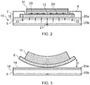
- the forces acting on the substrate 6 in the clamped condition during the build process are shown in Figure 2 . These include shear forces 20 at the interface 12 generated by the shrinkage of the metal as it solidifies and fuses to the substrate 6. These shear forces 20 are reacted by upward reaction forces 21 from the tool and downward reaction forces 22 from the clamps. If the clamps 7, 8 were released then the bending moment generated by the shear forces 20 would cause the part 11 and substrate 6 to become distorted as shown in Figure 3 .
- the tool 5, 25a, 25b and clamps 7, 8 are as light as possible so they can be manually moved relatively easily between the additive manufacturing system 1 and the heat treatment system 2.
- a collective weight of the tool 5, 25a, 25b and the clamps 7, 8 is less than ten times the collective weight of the substrate 6 and the part 11. More preferably a collective weight of the tool 5, 25a, 25b and the clamps 7, 8 is less than five times the collective weight of the substrate 6 and the part 11.
- Most preferably a collective weight of the tool 5, 25a, 25b and the clamps 7, 8 is less than twice the collective weight of the substrate 6 and the part 11.
- the heat treatment system 2 is operated to perform a heat treatment process by heating the part 11, the substrate 6 and the fixture 15 together thereby relieving the thermally induced stress in the part, the substrate remaining clamped to the tool during the heat treatment process.
- the heat treatment system 2 comprises a chamber 30 and heating elements 31 such as electric resistive heaters (or any other kind of heating element).
- the nature of the heat treatment process depends on a number of factors, principally the material of the part 11 - specifically the chemical composition of the feedstock material and the desired microstructure and properties of the part.
- the heat treatment process involves increasing the temperature to an elevated stress relieving temperature at which at least some of the thermally induced stress in the part 11 is relieved by a process of creep relaxation.
- the heating elements 31 are operated to increase the temperature in the chamber from room temperature up to an elevated stress relieving temperature of about 680°C over a period of about 90 minutes, the temperature is held at this elevated temperature for about 180 minutes, and then the heating elements 31 are turned off and the temperature returns to room temperature over a period of the order of 90 minutes.
- a lower stress relieving temperature of the order of 320°C can be used.
- the maximum bending stress generated in the tool 5, 25a, 25b by the internal stresses in the part 11 is much less than the stress at which the tool 5, 25a, 25b will experience plastic deformation at the heat treatment temperature, so the tool 5, 25a, 25b remains in the linear elastic regime during the heat treatment process.
- the tool 5, 25a, 25b is designed with sectional and material properties such that at the elevated stress relieving temperature the bending stiffness of the tool 5, 25a, 25b is much greater than the bending stiffness of the part 11 (typically at least ten times greater) measured perpendicular to the axis along which deposition takes place - in this case the vertical (Z) axis.
- E f is the elastic modulus of the material forming the fixture 15
- I 1 is the areal moment of inertia of the fixture 15
- E p is the elastic modulus of the material forming the part 11
- I p is the areal moment of inertia of the part 11. This ensures that the part 11 is held approximately flat during both the build process and the heat treatment process.
- the fixture 15, the substrate 6 and the part 11 are all heated during the heat treatment process.
- the tool 5, 25a, 25b and clamps 7, 8 are both formed from a material which is be able to withstand the high temperature of the heat treatment process. Also the thermal mass of the fixture 15 is designed to be relatively low so that the time (and energy) required to heat it up is not too great.
- a thermal mass of the fixture 15 is less than ten times the collective thermal mass of the substrate 6 and the part 11.
- a thermal mass of the fixture 15 is less than five times the collective thermal mass of the substrate 6 and the part 11. More preferably a thermal mass of the fixture 15 is less than twice the collective thermal mass of the substrate 6 and the part 11.
- a thermal mass of the fixture 15 is approximately equal to the collective weight of the substrate 6 and the part 11, in other words: Cp(fix) ⁇ m(fix) + Cp(cl) ⁇ m(cl) ⁇ Cp(sub) ⁇ m(sub) + Cp(part) ⁇ m(part), where Cp(fix) is the specific heat capacity of the tool 5, 25a, 25b; m(fix) is the mass of the tool 5, 25a, 25b; Cp(cl) is the specific heat capacity of the clamps 7, 8; m(cl) is the mass of the clamps 7, 8; Cp(sub) is the specific heat capacity of the substrate 6; m(sub) is the mass of the substrate 6; Cp(part) is the specific heat capacity of the part 11; and m(part) is the mass of the part 11.
- the fixture 15 may be beneficial for the fixture 15 to have a higher thermal mass than the substrate 6 and part 11.
- the temperature rise of the fixture 15 will lag behind the substrate 6 and part 11, increasing the difference between their respective stiffness and yield strengths.
- the substrate 6 is preferably formed from a material which is dissimilar to the material forming the upper surface 14 of the tool 5, 25a, 25b at the substrate/tool interface where they engage each other thereby inhibiting diffusion bonding between them during the heat treatment process.
- the substrate 6 is preferably formed from a material which is dissimilar to the material forming the clamps 7, 8 at the interface where they engage each other thereby inhibiting diffusion bonding between them during the heat treatment process.
- the substrate 6 is formed from a titanium alloy such as Ti6Al4V, i.e. the same material as the part 11.
- the upper reinforcement layer 25a When the tool bends upwards in the same sense as the substrate 6 and part 11 as shown in Figure 3 , the upper reinforcement layer 25a is in compression, the lower reinforcement layer 25b is in tension, and a neutral bending axis 18 is neither in compression nor in tension.
- the reinforcement layers 25a, 25b By placing the reinforcement layers 25a, 25b as far away as possible from the neutral axis 18, the bending stiffness of the tool is enhanced without adding much thermal mass.
- the neutral axis 18 is not at the mid-plane of the tool (i.e. the plane half way between the upper and lower reinforcement layers 25a, 25b) but rather it is offset from the mid-plane so it is closer to the upper reinforcement layer 25a. This upward offset of the neutral axis is due to the presence of the substrate 6 and part 11.
- Thermocouple temperature sensors 32, 33, 34 are used to measure the temperature of the lower reinforcement layer 25b, substrate 6 and part 11 respectively during the heat treatment process, and the measured temperatures are used to control the heating elements 31.
- the sensors 32 and 33 are integrated into the reinforcement layer 25b and clamp 8 respectively.
- the sensor 33 is thermally insulated from the clamp 8 but pressed into intimate engagement with the substrate 6 by the clamp.
- the fixture 15, substrate 6 and part 11 are removed together from the heat treatment chamber 30. Then the substrate 6 is released from the upper surface of the tool by removing the clamps 7, 8. The heat treatment process reduces the degree of distortion (distance D in Figure 3 ) when the clamps 7, 8 are released. Finally the part 11 and the substrate 6 are removed together from the fixture 15, the part 11 remaining bonded to the substrate 6 as they are removed.
- Figures 4-6 show an alternative fixture suitable for use in the process of Figure 1 .
- the fixture has two end clamps 40, 41 each of which is secured to the tool 42, 45a, 45b by four fasteners 40a, 41a; and four central clamps 43 each of which is secured to the tool by a respective fastener 43a.
- the clamps 40, 41, 43 are tightened by screwing the fasteners 41a, 43a into the tool, and released by removing the fasteners then lifting off the clamps.
- the reinforcement layers 45a, 45b are similar to the reinforcement layers 25a, 25b of the previous embodiment.
- the body 42 of the tool is deep relative to the thickness of the reinforcement layers 45a, 45b, in order to maximise its bending stiffness for a given amount of reinforcement material (noting that the reinforcement material is very expensive so it is not desirable to make the whole tool from this material).
- the upper and lower faces 42a, 42b of the body 42 of the tool are separated by an average depth D of the order of 100mm
- the upper reinforcement layer 45a has an average thickness T u of about 3-10mm
- the lower reinforcement layer 45b has an average thickness T l of about 3-10mm.
- each reinforcement layer 451, 45b has a thickness which is 3%-10% of the depth D of the body 42 between its upper and lower faces. This maximises the stiffening effect of the reinforcement layers 45a, 45b by spacing them far away from the neutral axis, whilst minimising the amount of expensive reinforcement material required.
- the mild steel body 42 has a pair of end faces 42c and a pair of side faces 42d. These end faces 42c and side faces 42d are unreinforced - that is, they are not clad with a reinforcement layer. Optionally the side faces 42d are clad with respective reinforcement layers made of the same reinforcement material as the upper and lower reinforcement layers.
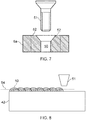
- FIG. 4-6 there are a number of clamps distributed around the periphery of the substrate 6, but in a further embodiment (not shown) a single "picture frame" clamp may be used to clamp the substrate to the tool around its full periphery.
- the substrate 6 is replaced by a substrate 6a with pre-formed undersized countersunk holes 50, only one of which is shown in Figure 7 .
- the substrate 6a is secured to the tool by a number of screws 51 or other fasteners, each of which passes through a respective hole 50 and is screwed into the tool below it.
- the screws 50 are released by removing them from their holes 50, and the substrate 6a is removed from the tool.
- the holes 50 are enlarged by drilling out material 52 to form cylindrical holes with parallel sides indicated by dotted lines in Figure 7 .
- bolts come in from the bottom of the fixture and engage in threaded holes in the substrate.
- Figure 8 illustrates a method of cladding either of the tools described above by a weld coating process.
- the upper reinforcement layer 42a is shown being formed on the upper face of the body 42 of the tool of Figure 6 , but the same process can be used to form any of the other reinforcement layers 25a, 25b, 42b.
- a welding head 51 deposits a series of lines 50 of molten reinforcement material (for instance InconelTM 625 or 718) onto the upper face of the body 42. Each line cools, solidifies and fuses to the upper face of the body, forming a continuous bond between the reinforcement layer and the upper face of the body 42 across the full area of the reinforcement layer. After the entire face has been clad, the reinforcement material is ground back to a desired level indicated by a dashed line 54.
- molten reinforcement material for instance InconelTM 625 or 712
- Alternative methods of forming and/or bonding the reinforcement layers include cold metal spraying, diffusion bonding and linear friction welding. Another possible method is to place the body of the tool in a mould, and pour molten reinforcement material into the mould so that it coats the upper and/or lower faces of the body.
- the material properties of the reinforcement material forming the reinforcement layers 25a, 25b; 42a, 42b are selected to enhance the stiffness and yield strength of the tool at high temperature, and ensure that the tool remains in the linear elastic regime during the heat treatment process.
- Tables 1-5 below show material properties of Ti6Al4V (a preferred material for the substrate 6 and the part 11); mild steel S355J2H (a preferred material for the body 5, 42 of the tool); InconelTM 718 (a first reinforcement material); InconelTM 625 (a second reinforcement material); and Tungsten (a third reinforcement material).
- Tables 1-5 may be determined by standard methods. Two ASTM standards that can be used for measuring yield strength and Young's modulus respectively are: ASTM E8/E8M - Standard Test Methods for Tension Testing of Metallic Materials; and ASTM E111 Standard Test Method for Young's Modulus, Tangent Modulus and Chord Modulus.
- Figures 9 and 10 illustrate some of the data of Tables 1-3 graphically.
- InconelTM 718 has a yield strength and Young's modulus which reduces much less (in percentage terms) with temperature than both Ti6Al4V and mild steel. For instance the Young's modulus and yield strength 0.2% reduce by only about 17% and 13% respectively between 93°C and 649°C.
- InconelTM 718 has a higher yield strength and Young's modulus than both Ti6Al4V and mild steel - particularly at high temperatures. Note that the Young's modulus of InconelTM 718 is about the same as mild steel at room temperature, but the Young's modulus of mild steel drops off quickly with temperature as shown in Figure 10 .
- the Young's modulus at 600°C of InconelTM 718 (about 175 GPa) is greater than the Young's modulus at 600°C of mild steel (65.1 GPa) by a factor of about 2.7.
- the yield strength 0.2% at 600°C of InconelTM718 (about 1050 MPa) is greater than the yield strength 0.2% at 600°C of mild steel (118 MPa) by a factor of about 8.9.
- Figure 11 shows an alternative tool which is identical to the tool of Figures 4-6 except it omits the upper reinforcement layer 45a. So in this case the lower reinforcement layer 45b clads the lower face 42b of the body 42, and the upper face 42a of the body is unreinforced - that is, it is not clad with a reinforcement layer.
- the attachment system 40, 41, 43 is configured to releasably secure the substrate 6 to the upper surface 14 of the tool, which in this case is the unreinforced upper face 42a of the body rather than the upper reinforcement layer as in the tool of Figures 4-6 .
- the upper surface 14 of the tool of Figure 11 comprises a coating of graphite which inhibits diffusion bonding between the substrate and the upper surface of the tool.
- a graphite coating would cover the upper reinforcement layer 25a, and in the case of Figure 11 it would cover the upper face 42a of the body 42 so the substrate is secured by the clamps in direct contact with the graphite coating, rather than in direct contact with the mild steel of the upper face 42a of the body 42.
- the tool of Figure 11 takes advantage of the fact that the lower face 42b of the body, being opposite the substrate, is further from the neutral axis than the upper face 42a of the body. So reinforcement material cladding the lower face 42b is more effective in stiffening the tool than reinforcement material cladding the upper face 42a.
- the tool of Figure 11 has an asymmetrical thermal expansion profile like a bi-metallic strip. That is, the reinforcement layer 45b will have a different thermal expansion coefficient to the mild steel of the body 42, which will result in a bending force being generated as the temperature rises. If the reinforcement material forming the reinforcement layer 45b has a lower thermal expansion coefficient than the mild steel, then this bending force will tend to counteract the bending forces which tend to bend the tool upwards as in Figure 3 . Therefore optionally the reinforcement material forming the reinforcement layer 45b is a low thermal expansion coefficient material which has a thermal expansion coefficient less than that of mild steel, and preferably also less than Ti6Al4V. A suitable low thermal expansion coefficient reinforcement is Tungsten or a Tungsten alloy.
- Tungsten has a thermal expansion coefficient at 100°C of 4 ⁇ 10 -6 K -1 which is less than half that of mild steel (11.7 ⁇ 10 -6 K -1 ) and Ti6Al4V (8.6 ⁇ 10 -6 K -1 ).
Landscapes
- Engineering & Computer Science (AREA)
- Chemical & Material Sciences (AREA)
- Manufacturing & Machinery (AREA)
- Physics & Mathematics (AREA)
- Materials Engineering (AREA)
- Optics & Photonics (AREA)
- Mechanical Engineering (AREA)
- Plasma & Fusion (AREA)
- Thermal Sciences (AREA)
- Crystallography & Structural Chemistry (AREA)
- Metallurgy (AREA)
- Organic Chemistry (AREA)
- General Engineering & Computer Science (AREA)
- Pressure Welding/Diffusion-Bonding (AREA)
- Powder Metallurgy (AREA)
- Other Surface Treatments For Metallic Materials (AREA)
Abstract
Description
- The present invention relates to a method and associated apparatus for additive manufacturing and heat treatment.
- Additive manufacturing typically involves the production of three-dimensional parts by depositing material layer by layer to build either complete components or add features to a pre-formed substrate. It contrasts with conventional subtractive machining processes, in that a component produced by an additive manufacturing process is near net shape, i.e. it is close to its final (net) shape thereby reducing the need for additional finishing and wasted excess material.
- A key challenge with additive manufacturing processes, particularly for the production of larger components, is the distortion of the manufactured part during the deposition process due to the high internal stresses generated as the deposited material solidifies.
- A solution to this problem is presented in
WO2014/072699 . A bed supports a parent plate of a work piece which is held in position by clamps. A stack of layers is built on the parent plate by a process of additive manufacturing, and stresses in the work piece are measured by load cells while progressively forming the stack. If such stresses are above a predetermined threshold, the work piece is stress relieved by a cold working process such as cold rolling or peening while mounted to the additive manufacturing apparatus. - In
US7344608 a substrate is clamped into a fixture and material is deposited thereon to form a complex article. The article produced is packed, using ceramic inserts and a coating. The packing ensures that the article maintains its true shape and allows for expansion during the subsequent heat treatment process. The packed article, mounted on the fixture, is then placed in a box, encased in a granular material and heated. It is heated to a temperature sufficient to relieve stresses and is maintained at this temperature for a time period such that the stresses in the article are relieved. - In
US2016/0108483 a substrate is secured to a fixture and an additive manufacturing system is operated to perform a build process by building a part on the substrate secured to the fixture. The part is built by forming a series of layers of metallic material on the substrate, the metallic material melting and solidifying during the build process thereby bonding the part to the substrate and creating thermally induced stress in the part. The part, the substrate and the fixture are moved together from the additive manufacturing system to a heat treatment system, wherein the substrate remains secured to the fixture and the part remains bonded to the substrate as they are moved. The heat treatment system is operated to perform a heat treatment process by heating the part, the substrate and the fixture together thereby relieving the thermally induced stress in the part, the substrate remaining secured to the fixture during the heat treatment process. Finally the substrate is released from the fixture and the part and the substrate are removed from the fixture. The part remains bonded to the support as they are removed from the fixture. - Ideally the maximum bending stress generated in the fixture by the internal stresses in the part is much less than the stress at which the fixture will experience plastic deformation at the heat treatment temperature, so the fixture remains in the linear elastic regime during the heat treatment process. However, surprisingly it has been found that extreme bending stresses can be generated which cause the fixture to experience plastic deformation. As a result the fixture must either be repaired to restore it to its previous shape, or scrapped.
- A first aspect of the invention provides a fixture for use in an additive manufacturing and heat treatment process, the fixture comprising: a tool with an upper surface and a lower surface; and an attachment system configured to releasably secure a substrate to the upper surface of the tool, wherein the tool comprises a body with an upper face and a lower face, and a reinforcement layer cladding the upper or lower face of the body.
- Typically the body comprises a body material and the reinforcement layer comprises a reinforcement material which is different to the body material.
- The attachment system may comprises one or more attachment members (such as clamps or fasteners).
- Optionally the reinforcement layer is a lower reinforcement layer cladding the lower face of the body opposite the upper surface of the tool. This places the reinforcement layer well away from the upper surface of the tool and well away from a neutral bending axis of the tool, enhancing the stiffness of the tool.
- Optionally the lower reinforcement layer has a lower thermal expansion coefficient at 100°C than the body, preferably more than 20% lower.
- Alternatively the reinforcement layer is an upper reinforcement layer cladding the upper face of the body. In this case the tool may also comprise a lower reinforcement layer cladding the lower face of the body opposite the upper reinforcement layer, or the lower face of the body may be unreinforced (i.e. not clad with a reinforcement layer).
- Optionally the upper surface of the tool comprises a coating of graphite which inhibits diffusion bonding between the substrate and the upper surface of the tool. This graphite coating may cover the reinforcement layer or it may cover the upper face of the body. Alternatively the upper surface of the tool may comprise the reinforcement layer or the upper face of the body - in this case the substrate is secured by the attachment system in direct contact with the reinforcement layer or the upper face of the body (rather than being in contact with a graphite coating).
- Where both upper and lower reinforcement layers are provided, then they may comprise the same reinforcement material, or different reinforcement materials.
- Preferably the or each reinforcement layer comprises a metal reinforcement material. The metal reinforcement material may be a pure metal such as Tungsten; or a metal alloy such as a Nickel alloy, Tungsten alloy or Cobalt alloy (such as cobalt chrome).
- Optionally the or each reinforcement layer comprises a metal superalloy or high temperature alloy, such as Inconel™ 625 or Inconel™ 718.
- Optionally the body comprises a metal body material, typically a metal alloy body material such as mild steel.
- The or each reinforcement layer may have a thickness greater than 1mm, greater than 2mm, greater than 3mm or greater than 4mm. Typically the or each reinforcement layer has a thickness which is more than 1% or more than 2% of a depth of the body between its upper and lower faces.
- The or each reinforcement layer may have a thickness less than 30mm, less than 20mm, less than 10mm, less than 9mm, less than 8mm or less than 6mm.
- Optionally the body has a depth between its upper and lower faces which is greater than 50mm, greater than 60mm or greater than 70mm.
- Optionally the or each reinforcement layer has a thickness which is less than a depth of the body between its upper and lower faces, typically by a factor of five or more. Optionally the upper and lower faces of the body are separated by a depth of the body, and the or each reinforcement layer has a thickness which is less than the depth of the body.
- Typically the or each reinforcement layer has a thickness which is no more than 10% of a depth of the body between its upper and lower faces. Preferably the or each reinforcement layer comprises a reinforcement material with a Young's modulus which reduces by less than 30% or less than 20% between 93°C and 649°C.
- Preferably the or each reinforcement layer comprises a reinforcement material with a yield strength 0.2% which reduces by less than 30% or less than 20% between 93°C and 649°C.
- Preferably the or each reinforcement layer comprises a reinforcement material with a Young's modulus at 500°C which is greater than 100GPa or greater than 150GPa. Optionally the or each reinforcement layer comprises a reinforcement material with a Young's modulus at 600°C which is greater than 100GPa or greater than 150GPa.
- Preferably the body comprises a body material; the or each reinforcement layer comprises a reinforcement material; and a Young's modulus at 500°C of the or each reinforcement material is greater than a Young's modulus at 500°C of the body material. Optionally a Young's modulus at 600°C of the or each reinforcement material is greater than a Young's modulus at 600°C of the body material, preferably by a factor of two or more.
- Preferably the or each reinforcement layer comprises a reinforcement material with a yield strength 0.2% at 500°C which is greater than 400 MPa or greater than 600 MPa. Optionally the or each reinforcement layer comprises a reinforcement material with a yield strength 0.2% at 600°C which is greater than 400 MPa or greater than 600 MPa.
- Preferably the body comprises a body material; the or each reinforcement layer comprises a reinforcement material; and a yield strength 0.2% at 500°C of the or each reinforcement material is greater than a yield strength 0.2% at 500°C of the body material, preferably by a factor of two or more. Optionally a yield strength 0.2% at 600°C of the or each reinforcement material is greater than a yield strength 0.2% at 600°C of the body material, preferably by a factor of four or more.
- Optionally the or each reinforcement layer is bonded to the body, for instance by weld coating, spray forming or diffusion bonding.
- Preferably the or each reinforcement layer is bonded to the body across a full area of the reinforcement layer, rather than being attached by fasteners or bonded at certain points only.
- Optionally the body has a pair of end faces and a pair of side faces; and the end faces are unreinforced.
- Optionally the body comprises a single continuous block of a body material, rather than a lattice structure.
- Optionally the reinforcement layer clads the upper or lower face of the body, and the lower or upper face of the body opposite the reinforcement layer is unreinforced (in other words it is not clad with a reinforcement layer). In this case, then optionally the reinforcement layer has a different thermal expansion coefficient at 100°C to the body, preferably differing by a factor of 20% or more.
- In one embodiment the reinforcement layer clads the lower face of the body opposite the upper surface of the tool; the upper face of the body is not clad in reinforcement material; and the reinforcement layer has a lower thermal expansion coefficient at 100°C than the body, preferably more than 20% lower.
- A further aspect of the invention provides a method of manufacturing the fixture of the first aspect, the method comprising cladding the body with the or each reinforcement layer by a weld coating process or a spraying process (such as cold metal spraying).
- A further aspect of the invention provides a method of additive manufacturing and heat treatment, the method comprising: a) providing a fixture according to the first aspect of the invention; b) securing a substrate to the upper surface of the tool with the attachment system; c) operating an additive manufacturing system to perform a build process by building a part on the substrate secured to the tool, the part being built by forming a series of layers of metallic material on the substrate, the metallic material melting and solidifying during the build process thereby bonding the part to the substrate and creating thermally induced stress in the part; d) moving the part, the substrate and the fixture from the additive manufacturing system to a heat treatment system, wherein the substrate remains secured to the tool and the part remains bonded to the substrate as they are moved; e) operating the heat treatment system to perform a heat treatment process by heating the part, the substrate and the fixture together thereby relieving the thermally induced stress in the part, the substrate remaining secured to the tool during the heat treatment process; f) operating the attachment system to release the substrate from the tool so that the substrate is no longer secured to the tool by the attachment system; and g) separating the part and the substrate from the fixture, wherein the part remains bonded to the substrate as they are separated from the fixture.
- A further aspect of the invention provides apparatus for performing the method of the preceding aspect, the apparatus comprising: an additive manufacturing system which can be operated to perform the build process; a heat treatment system which can be operated to perform the heat treatment process; and a fixture according to the first aspect which can be moved between the additive manufacturing system and the heat treatment system.
- A wide variety of additive manufacturing process may be employed, including (but not limited to) directed energy deposition (in which thermal energy is used to fuse the metallic material as it is deposited); powder bed fusion (in which thermal energy selectively fuses regions of a powder bed); or any other additive manufacturing process which creates thermally induced stress in the built part. In one embodiment of the invention the additive manufacturing process forms the series of layers of metallic material on the substrate by feeding metallic feedstock material and melting the metallic feedstock material with a laser beam, electric current or other thermal energy source as it is deposited.
- The attachment system may comprises one or more attachment members (such as clamps or fasteners) which are engaged with the substrate in step b) and disengaged from the substrate in step f).
- Preferably the substrate is secured to the tool by one or more clamps or fasteners in step b); and the (or each) clamp or fastener is released in step f) so that the substrate is no longer secured to the tool. Where fasteners are used, then the substrate may be secured to the tool by one or more fasteners in step b) by passing the (or each) fastener through a respective pre-formed hole in the substrate; and the (or each) fastener released in step f) by removing it from its respective pre-formed hole in the substrate.
- Typically the substrate contacts the tool at a substrate/tool interface at the upper surface of the tool during the heat treatment process. Preferably the substrate and tool are formed from dissimilar materials at the substrate/tool interface, thereby inhibiting bonding between them at the substrate/tool interface during the heat treatment process.
- During the heat treatment process the temperatures of the part, the substrate and the fixture are typically increased to above 150°C and maintained above 150°C for more than 30 minutes.
- During the heat treatment process the temperatures of the part, the substrate and the fixture are optionally increased to above 500°C and maintained above 500°C for more than 30 minutes.
- A temperature sensor may be integrated into the tool or the attachment system and arranged to measure temperature during the heat treatment process.
- Preferably the fixture has a mass which is less than ten times, preferably less than five times, and most preferably less than two times a collective mass of the substrate and the part. This makes it easy to transfer them between the additive manufacturing system and the heat treatment system.
- The part and the substrate are typically separated from the fixture by removing them from the fixture, although conceivably they could be separated from the fixture by moving the fixture rather than by moving the part and the substrate.
- Typically all steps of the method are performed in order a) to g).
- Embodiments of the invention will now be described with reference to the accompanying drawings, in which:
-
Figure 1 illustrates an additive manufacturing system and heat treatment system; -
Figure 2 illustrates the forces acting on the substrate in the clamped condition during deposition; -
Figure 3 illustrates the distortion which would result if the clamps were released before heat treatment; -
Figure 4 is a plan view of an alternative tooling arrangement; -
Figure 5 is a side view of the tooling arrangement ofFigure 4 ; -
Figure 6 is an isometric view of the tooling arrangement ofFigure 4 ; -
Figure 7 shows an alternative method of securing the substrate to the tool; -
Figure 8 shows a method of forming one of the reinforcement layers; -
Figure 9 is a graph of yield strength 0.2% versus temperature; -
Figure 10 is a graph of Young's module versus temperature; and -
Figure 11 shows a further alternative tooling arrangement with only a lower reinforcement layer. -
Figure 1 shows anadditive manufacturing system 1 and aheat treatment system 2. Theadditive manufacturing system 1 comprises a chamber containing a table 3 and abuild head 4. Afixture 15 is shown inFigure 1 on the table 3. Thefixture 15 comprises atool clamps - The tool comprises a
body 5 and a pair ofreinforcement layers body 5 comprises a continuous block of body material (for instance mild steel S355J2H) with anupper face 5a and alower face 5b. Theupper reinforcement layer 25a clads the externalupper face 5a of the body, and thelower reinforcement layer 25b clads the externallower face 5b of the body. The upper andlower reinforcement layers - The tool has an upper surface 14 (the external face of the
upper reinforcement layer 25a) and a lower surface (the external face of thelower reinforcement layer 25b) opposite theupper surface 14. In a first step, asubstrate 6 is placed on theupper surface 14 of the tool and secured byclamps upper surface 14 of the tool. Theupper surface 14 of the tool is the external face of theupper reinforcement layer 25a, so thesubstrate 6 is in direct contact with the reinforcement material rather than the mild steel forming thebody 5. - Optionally the
upper surface 14 of the tool comprises a coating of graphite which covers theupper reinforcement layer 25a and inhibits diffusion bonding between thesubstrate 6 and the reinforcement material. So in this case thesubstrate 6 would by secured by theclamps upper reinforcement layer 25a. - The
substrate 6 is pre-formed, in other words it is not formed by additive manufacturing on the tool. Typically thesubstrate 6 is secured to the tool outside the chamber of theadditive manufacturing system 1, and then thefixture 15 carrying thesubstrate 6 is introduced into the chamber and placed on the table 3. - In a second step, the
build head 4 is operated to perform a build process by building a nearnet shape part 11 on thesubstrate 6 secured to the tool. Thebuild head 4 feeds metallic feedstock material 9 (such as titanium alloy or aluminium alloy) towards thesubstrate 6, and thematerial 9 is melted by alaser beam 10 as it is fed onto thesubstrate 6. Thefeedstock material 9 may be fed in the form of a wire or a blown powder, for example. Thebuild head 4 is scanned across thesubstrate 6 to build a part by forming a series of layers of metallic material on thesubstrate 6. These layers include a first layer which fuses to the substrate at a part/substrate interface 12, and a series of additional layers each of which fuses with a previously deposited layer. One of theseadditional layers 13 is shown in the process of being laid down by thebuild head 4. The shape and size of each layer is determined in accordance with a computer aided design (CAD) model of thepart 11 stored in a memory. Although the layers are all identical inFigure 1 for ease of illustration, they may in general have different shapes and/or sizes. - The metallic material melts and solidifies during the build process, thereby fusing the
part 11 to thesubstrate 6 and creating thermally induced stress in thepart 11. The forces acting on thesubstrate 6 in the clamped condition during the build process are shown inFigure 2 . These includeshear forces 20 at theinterface 12 generated by the shrinkage of the metal as it solidifies and fuses to thesubstrate 6. Theseshear forces 20 are reacted by upward reaction forces 21 from the tool anddownward reaction forces 22 from the clamps. If theclamps shear forces 20 would cause thepart 11 andsubstrate 6 to become distorted as shown inFigure 3 . - Returning to
Figure 1 , after thepart 11 has been fully built, thepart 11, thesubstrate 6 and thefixture 15 are lifted off the table 3, removed from the chamber, and moved together to theheat treatment system 2. Thesubstrate 6 remains clamped to the tool and thepart 11 remains bonded to thesubstrate 6 as they are moved. - The
tool additive manufacturing system 1 and theheat treatment system 2. Typically a collective weight of thetool clamps substrate 6 and thepart 11. More preferably a collective weight of thetool clamps substrate 6 and thepart 11. Most preferably a collective weight of thetool clamps substrate 6 and thepart 11. - Next the
heat treatment system 2 is operated to perform a heat treatment process by heating thepart 11, thesubstrate 6 and thefixture 15 together thereby relieving the thermally induced stress in the part, the substrate remaining clamped to the tool during the heat treatment process. Theheat treatment system 2 comprises achamber 30 andheating elements 31 such as electric resistive heaters (or any other kind of heating element). The nature of the heat treatment process depends on a number of factors, principally the material of the part 11 - specifically the chemical composition of the feedstock material and the desired microstructure and properties of the part. Generally speaking, the heat treatment process involves increasing the temperature to an elevated stress relieving temperature at which at least some of the thermally induced stress in thepart 11 is relieved by a process of creep relaxation. - In one example, in the case where the
part 11 andsubstrate 6 are formed from a titanium alloy such as Ti6Al4V, theheating elements 31 are operated to increase the temperature in the chamber from room temperature up to an elevated stress relieving temperature of about 680°C over a period of about 90 minutes, the temperature is held at this elevated temperature for about 180 minutes, and then theheating elements 31 are turned off and the temperature returns to room temperature over a period of the order of 90 minutes. In another example, in which thepart 11 andsubstrate 6 are formed from an aluminium alloy, then a lower stress relieving temperature of the order of 320°C can be used. - Ideally the maximum bending stress generated in the
tool part 11 is much less than the stress at which thetool tool - The
tool tool fixture 15, I1 is the areal moment of inertia of thefixture 15, Ep is the elastic modulus of the material forming thepart 11 and Ip is the areal moment of inertia of thepart 11. This ensures that thepart 11 is held approximately flat during both the build process and the heat treatment process. - Note that the
fixture 15, thesubstrate 6 and thepart 11 are all heated during the heat treatment process. Thetool fixture 15 is designed to be relatively low so that the time (and energy) required to heat it up is not too great. - Typically a thermal mass of the
fixture 15 is less than ten times the collective thermal mass of thesubstrate 6 and thepart 11. Preferably a thermal mass of thefixture 15 is less than five times the collective thermal mass of thesubstrate 6 and thepart 11. More preferably a thermal mass of thefixture 15 is less than twice the collective thermal mass of thesubstrate 6 and thepart 11. - Optionally a thermal mass of the
fixture 15 is approximately equal to the collective weight of thesubstrate 6 and thepart 11, in other words: Cp(fix)∗m(fix) + Cp(cl)∗m(cl) ≈ Cp(sub)∗m(sub) + Cp(part)∗m(part), where Cp(fix) is the specific heat capacity of thetool tool clamps clamps substrate 6; m(sub) is the mass of thesubstrate 6; Cp(part) is the specific heat capacity of thepart 11; and m(part) is the mass of thepart 11. - Making the collective thermal masses approximately equal means that the various elements will tend to heat and cool at a similar rate during and immediately after the heat treatment process.
- Alternatively it may be beneficial for the
fixture 15 to have a higher thermal mass than thesubstrate 6 andpart 11. The temperature rise of thefixture 15 will lag behind thesubstrate 6 andpart 11, increasing the difference between their respective stiffness and yield strengths. - The
substrate 6 is preferably formed from a material which is dissimilar to the material forming theupper surface 14 of thetool substrate 6 is preferably formed from a material which is dissimilar to the material forming theclamps - Optionally the
substrate 6 is formed from a titanium alloy such as Ti6Al4V, i.e. the same material as thepart 11. - When the tool bends upwards in the same sense as the
substrate 6 andpart 11 as shown inFigure 3 , theupper reinforcement layer 25a is in compression, thelower reinforcement layer 25b is in tension, and aneutral bending axis 18 is neither in compression nor in tension. By placing the reinforcement layers 25a, 25b as far away as possible from theneutral axis 18, the bending stiffness of the tool is enhanced without adding much thermal mass. Note that theneutral axis 18 is not at the mid-plane of the tool (i.e. the plane half way between the upper andlower reinforcement layers upper reinforcement layer 25a. This upward offset of the neutral axis is due to the presence of thesubstrate 6 andpart 11. -
Thermocouple temperature sensors lower reinforcement layer 25b,substrate 6 andpart 11 respectively during the heat treatment process, and the measured temperatures are used to control theheating elements 31. Thesensors reinforcement layer 25b andclamp 8 respectively. Thesensor 33 is thermally insulated from theclamp 8 but pressed into intimate engagement with thesubstrate 6 by the clamp. - When the heat treatment process is complete, the
fixture 15,substrate 6 andpart 11 are removed together from theheat treatment chamber 30. Then thesubstrate 6 is released from the upper surface of the tool by removing theclamps Figure 3 ) when theclamps part 11 and thesubstrate 6 are removed together from thefixture 15, thepart 11 remaining bonded to thesubstrate 6 as they are removed. -
Figures 4-6 show an alternative fixture suitable for use in the process ofFigure 1 . In this case the fixture has two end clamps 40, 41 each of which is secured to thetool fasteners central clamps 43 each of which is secured to the tool by arespective fastener 43a. The clamps 40, 41, 43 are tightened by screwing thefasteners - The reinforcement layers 45a, 45b are similar to the reinforcement layers 25a, 25b of the previous embodiment.
- As shown by a comparison of
Figure 4 withFigure 5 , thebody 42 of the tool is deep relative to the thickness of the reinforcement layers 45a, 45b, in order to maximise its bending stiffness for a given amount of reinforcement material (noting that the reinforcement material is very expensive so it is not desirable to make the whole tool from this material). More specifically, the upper andlower faces body 42 of the tool are separated by an average depth D of the order of 100mm, theupper reinforcement layer 45a has an average thickness Tu of about 3-10mm, and thelower reinforcement layer 45b has an average thickness Tl of about 3-10mm. Thus eachreinforcement layer 451, 45b has a thickness which is 3%-10% of the depth D of thebody 42 between its upper and lower faces. This maximises the stiffening effect of the reinforcement layers 45a, 45b by spacing them far away from the neutral axis, whilst minimising the amount of expensive reinforcement material required. - As shown in
Figures 4 and6 , themild steel body 42 has a pair of end faces 42c and a pair of side faces 42d. These end faces 42c and side faces 42d are unreinforced - that is, they are not clad with a reinforcement layer. Optionally the side faces 42d are clad with respective reinforcement layers made of the same reinforcement material as the upper and lower reinforcement layers. - In the example of
Figures 4-6 there are a number of clamps distributed around the periphery of thesubstrate 6, but in a further embodiment (not shown) a single "picture frame" clamp may be used to clamp the substrate to the tool around its full periphery. - In a further embodiment shown in
Figure 7 , thesubstrate 6 is replaced by asubstrate 6a with pre-formed undersized countersunk holes 50, only one of which is shown inFigure 7 . Rather than being secured to the upper surface of the tool by clamps, thesubstrate 6a is secured to the tool by a number ofscrews 51 or other fasteners, each of which passes through arespective hole 50 and is screwed into the tool below it. After thepart 11 has been built on thesubstrate 6a, thescrews 50 are released by removing them from theirholes 50, and thesubstrate 6a is removed from the tool. Then theholes 50 are enlarged by drilling outmaterial 52 to form cylindrical holes with parallel sides indicated by dotted lines inFigure 7 . - In a further embodiment (not shown) bolts come in from the bottom of the fixture and engage in threaded holes in the substrate.
-
Figure 8 illustrates a method of cladding either of the tools described above by a weld coating process. In this example theupper reinforcement layer 42a is shown being formed on the upper face of thebody 42 of the tool ofFigure 6 , but the same process can be used to form any of theother reinforcement layers - A
welding head 51 deposits a series oflines 50 of molten reinforcement material (for instance Inconel™ 625 or 718) onto the upper face of thebody 42. Each line cools, solidifies and fuses to the upper face of the body, forming a continuous bond between the reinforcement layer and the upper face of thebody 42 across the full area of the reinforcement layer. After the entire face has been clad, the reinforcement material is ground back to a desired level indicated by a dashedline 54. - Alternative methods of forming and/or bonding the reinforcement layers include cold metal spraying, diffusion bonding and linear friction welding. Another possible method is to place the body of the tool in a mould, and pour molten reinforcement material into the mould so that it coats the upper and/or lower faces of the body.
- The material properties of the reinforcement material forming the reinforcement layers 25a, 25b; 42a, 42b are selected to enhance the stiffness and yield strength of the tool at high temperature, and ensure that the tool remains in the linear elastic regime during the heat treatment process.
- Tables 1-5 below show material properties of Ti6Al4V (a preferred material for the
substrate 6 and the part 11); mild steel S355J2H (a preferred material for thebody - In Tables 1-5, temperature is given in °C, the coefficient of linear expansion is given in 10-6 K-1, the Young's modulus E is given in Gpa, and the yield strength is given as the stress in MPa at which a permanent deformation of 0.2% of the original dimension will result.
- The parameters in Tables 1-5 may be determined by standard methods. Two ASTM standards that can be used for measuring yield strength and Young's modulus respectively are: ASTM E8/E8M - Standard Test Methods for Tension Testing of Metallic Materials; and ASTM E111 Standard Test Method for Young's Modulus, Tangent Modulus and Chord Modulus.
Table 1 Ti6Al4V Linear expansion E Yield Strength 0.2% Temp Coefficient Temp G Pa Temp M Pa 20 to 100 8.6 20 114 0 900 20 to 315 9.2 100 114 100 800 20 to 650 9.7 200 114 200 760 300 85 300 570 400 85 400 500 500 75 500 480 600 42 Table 2 Mild Steel - Structural Steel - S355J2H Linear expansion E Yield Strength 0.2% Temp Coefficient Temp G Pa Temp M Pa 0 to 250 11.7 20 210 20 520 0 to 500 12.8 100 210 100 520 0 to 1000 13.9 200 189 200 485 300 168 300 439 400 147 400 381 500 126 500 255 600 65.1 600 118 700 27.3 700 66 Table 3 Inconel™ 718 Linear expansion E Yield Strength 0.2% Temp Coefficient Temp G Pa Temp M Pa 21 208 21 200 12.8 93 205 93 1172 400 13.5 204 202 204 1124 600 13.9 316 194 316 1096 800 14.2 427 186 427 1076 1000 14.4 538 179 538 1069 1200 15.1 649 172 649 1027 1400 16 760 162 760 758 871 127 Table 4 Inconel™ 625 Linear expansion E Yield Strength 0.2% Temp Coefficient Temp G Pa Temp M Pa 21 207.5 21 414 93 12.8 93 204.1 204 13.1 204 197.9 316 13.3 316 191.7 427 13.7 427 185.5 538 14 538 178.6 649 734.3 649 14.8 649 170.3 760 544.7 760 15.3 760 160.6 871 275.8 871 15.8 871 147.5 927 16.2 Table 5 Tungsten Linear expansion E Yield Strength 0.2% Temp Coefficient Temp G Pa Temp M Pa 20 400 20 750 100 4.4 800 370 1200 350 1800 300 -
Figures 9 and 10 illustrate some of the data of Tables 1-3 graphically. - It can be seen from
Figures 9 and 10 that Inconel™ 718 has a yield strength and Young's modulus which reduces much less (in percentage terms) with temperature than both Ti6Al4V and mild steel. For instance the Young's modulus and yield strength 0.2% reduce by only about 17% and 13% respectively between 93°C and 649°C. - It can also be seen from
Figures 9 and 10 that Inconel™ 718 has a higher yield strength and Young's modulus than both Ti6Al4V and mild steel - particularly at high temperatures. Note that the Young's modulus of Inconel™ 718 is about the same as mild steel at room temperature, but the Young's modulus of mild steel drops off quickly with temperature as shown inFigure 10 . - The Young's modulus at 600°C of Inconel™ 718 (about 175 GPa) is greater than the Young's modulus at 600°C of mild steel (65.1 GPa) by a factor of about 2.7.
- The yield strength 0.2% at 600°C of Inconel™718 (about 1050 MPa) is greater than the yield strength 0.2% at 600°C of mild steel (118 MPa) by a factor of about 8.9.
-
Figure 11 shows an alternative tool which is identical to the tool ofFigures 4-6 except it omits theupper reinforcement layer 45a. So in this case thelower reinforcement layer 45b clads thelower face 42b of thebody 42, and theupper face 42a of the body is unreinforced - that is, it is not clad with a reinforcement layer. Theattachment system substrate 6 to theupper surface 14 of the tool, which in this case is the unreinforcedupper face 42a of the body rather than the upper reinforcement layer as in the tool ofFigures 4-6 . - Optionally the
upper surface 14 of the tool ofFigure 11 comprises a coating of graphite which inhibits diffusion bonding between the substrate and the upper surface of the tool. In the case ofFigures 4-6 such a graphite coating would cover theupper reinforcement layer 25a, and in the case ofFigure 11 it would cover theupper face 42a of thebody 42 so the substrate is secured by the clamps in direct contact with the graphite coating, rather than in direct contact with the mild steel of theupper face 42a of thebody 42. - The tool of
Figure 11 takes advantage of the fact that thelower face 42b of the body, being opposite the substrate, is further from the neutral axis than theupper face 42a of the body. So reinforcement material cladding thelower face 42b is more effective in stiffening the tool than reinforcement material cladding theupper face 42a. - The tool of
Figure 11 has an asymmetrical thermal expansion profile like a bi-metallic strip. That is, thereinforcement layer 45b will have a different thermal expansion coefficient to the mild steel of thebody 42, which will result in a bending force being generated as the temperature rises. If the reinforcement material forming thereinforcement layer 45b has a lower thermal expansion coefficient than the mild steel, then this bending force will tend to counteract the bending forces which tend to bend the tool upwards as inFigure 3 . Therefore optionally the reinforcement material forming thereinforcement layer 45b is a low thermal expansion coefficient material which has a thermal expansion coefficient less than that of mild steel, and preferably also less than Ti6Al4V. A suitable low thermal expansion coefficient reinforcement is Tungsten or a Tungsten alloy. As shown in Table 5 above, Tungsten has a thermal expansion coefficient at 100°C of 4∗10-6 K-1 which is less than half that of mild steel (11.7∗10-6 K-1) and Ti6Al4V (8.6∗10-6 K-1). - Although the invention has been described above with reference to one or more preferred embodiments, it will be appreciated that various changes or modifications may be made without departing from the scope of the invention as defined in the appended claims.
Claims (15)
- A fixture (15) for use in an additive manufacturing and heat treatment process, the fixture comprising: a tool with an upper surface (14) and a lower surface; and an attachment system (7, 8) configured to releasably secure a substrate to the upper surface of the tool, wherein the tool comprises a body (5) with an upper face (5a) and a lower face (5b), and a reinforcement layer (25a, 25b) cladding the upper or lower face of the body.
- A fixture according to claim 1 wherein the reinforcement layer is a lower reinforcement layer (25b) cladding the lower face of the body.
- A fixture according to claim 2 wherein the lower reinforcement layer (25b) has a lower thermal expansion coefficient than the body.
- A fixture according to claim 1 wherein the reinforcement layer is an upper reinforcement layer (25a) cladding the upper face of the body.
- A fixture according to claim 4 further comprising a lower reinforcement layer (25b) cladding the lower face of the body.
- A fixture according to any preceding claim wherein the or each reinforcement layer (25a, 25b) comprises a metal reinforcement material.
- A fixture according to any preceding claim wherein the or each reinforcement layer (25a, 25b) has a thickness greater than 1mm, and/or the or each reinforcement layer has a thickness less than 30mm.
- A fixture according to any preceding claim wherein the or each reinforcement layer (25a, 25b) comprises a reinforcement material with a Young's modulus and/or yield strength 0.2% which reduces by less than 30% or less than 20% between 93°C and 649°C.
- A fixture according to any preceding claim wherein the or each reinforcement layer (25a, 25b) comprises a reinforcement material with a Young's modulus at 500°C which is greater than 100GPa or greater than 150GPa.
- A fixture according to any preceding claim wherein the body (5) comprises a body material; the or each reinforcement layer (25a, 25b) comprises a reinforcement material; a Young's modulus at 500°C of the or each reinforcement material is greater than a Young's modulus at 500°C of the body material; and/or a yield strength 0.2% at 500°C of the or each reinforcement material is greater than a yield strength 0.2% at 500°C of the body material.
- A fixture according to any preceding claim wherein the or each reinforcement layer (25a, 25b) comprises a reinforcement material with a yield strength 0.2% at 500°C which is greater than 400 MPa or greater than 600 MPa.
- A fixture according to any preceding claim wherein the reinforcement layer (25a, 25b) clads the upper or lower face of the body, and the lower or upper face of the body opposite the reinforcement layer is not clad in reinforcement material.
- A method of manufacturing the fixture of any preceding claim, the method comprising cladding the body (5) with the or each reinforcement layer (25a, 25b) by a welding process or a spraying process.
- A method of additive manufacturing and heat treatment, the method comprising:a. providing a fixture (15) according to claim 1;b. securing a substrate (6) to the upper surface of the tool with the attachment system (7, 8);c. operating an additive manufacturing system (1) to perform a build process by building a part (11) on the substrate (6) secured to the tool, the part being built by forming a series of layers (13) of metallic material on the substrate, the metallic material melting and solidifying during the build process thereby bonding the part to the substrate and creating thermally induced stress in the part;d. moving the part (11), the substrate (6) and the fixture (15) from the additive manufacturing system to a heat treatment system, wherein the substrate remains secured to the tool and the part remains bonded to the substrate as they are moved;e. operating the heat treatment system (2) to perform a heat treatment process by heating the part (11), the substrate (6) and the fixture (15) together thereby relieving the thermally induced stress in the part, the substrate remaining secured to the tool during the heat treatment process;f. operating the attachment system (7, 8) to release the substrate from the tool so that the substrate is no longer secured to the tool by the attachment system; andg. separating the part (11) and the substrate (6) from the fixture (15), wherein the part remains bonded to the substrate as they are separated from the fixture.
- Apparatus for performing the method of claim 14, the apparatus comprising:a. an additive manufacturing system (1) which can be operated to perform the build process;b. a heat treatment system (2) which can be operated to perform the heat treatment process; andc. a fixture (15) according to claim 1 which can be moved between the additive manufacturing system (1) and the heat treatment system (2).
Applications Claiming Priority (1)
| Application Number | Priority Date | Filing Date | Title |
|---|---|---|---|
| GB1904060.9A GB2582567A (en) | 2019-03-25 | 2019-03-25 | Fixture for additive manufacturing and heat treatment |
Publications (1)
| Publication Number | Publication Date |
|---|---|
| EP3718663A1 true EP3718663A1 (en) | 2020-10-07 |
Family
ID=66381279
Family Applications (1)
| Application Number | Title | Priority Date | Filing Date |
|---|---|---|---|
| EP20162455.8A Withdrawn EP3718663A1 (en) | 2019-03-25 | 2020-03-11 | Fixture for additive manufacturing and heat treatment |
Country Status (4)
| Country | Link |
|---|---|
| US (1) | US12042867B2 (en) |
| EP (1) | EP3718663A1 (en) |
| CN (1) | CN111730056B (en) |
| GB (1) | GB2582567A (en) |
Citations (7)
| Publication number | Priority date | Publication date | Assignee | Title |
|---|---|---|---|---|
| US20030206820A1 (en) * | 1999-07-07 | 2003-11-06 | Keicher David M. | Forming structures from CAD solid models |
| US7344608B2 (en) | 2003-12-17 | 2008-03-18 | Rolls-Royce Plc | Method and apparatus for heat-treating an article and a fixture for use in the same |
| GB2500412A (en) * | 2012-03-21 | 2013-09-25 | Eads Uk Ltd | Build Plate for an additive manufacturing process |
| WO2014072699A1 (en) | 2012-11-09 | 2014-05-15 | Bae Systems Plc | Additive layer manufacturing |
| US20160108483A1 (en) | 2014-10-17 | 2016-04-21 | Airbus Group Limited | Method of Additive Manufacturing and Heat Treatment |
| EP3406371A1 (en) * | 2017-05-22 | 2018-11-28 | Siemens Aktiengesellschaft | Method of relieving mechanical stress in additive manufacturing |
| EP3427870A1 (en) * | 2016-03-09 | 2019-01-16 | Panasonic Intellectual Property Management Co., Ltd. | Three-dimensional molded object production method |
Family Cites Families (14)
| Publication number | Priority date | Publication date | Assignee | Title |
|---|---|---|---|---|
| US6925346B1 (en) | 1998-06-30 | 2005-08-02 | Jyoti Mazumder | Closed-loop, rapid manufacturing of three-dimensional components using direct metal deposition |
| US7851966B2 (en) * | 2008-01-10 | 2010-12-14 | Rippel Wally E | Stator for electric machine with improved efficiency and thermal performance |
| JP5061062B2 (en) | 2008-08-08 | 2012-10-31 | パナソニック株式会社 | Manufacturing method of three-dimensional shaped object |
| US20110268989A1 (en) * | 2010-04-29 | 2011-11-03 | General Electric Company | Cobalt-nickel superalloys, and related articles |
| US8986604B2 (en) | 2010-10-20 | 2015-03-24 | Materials Solutions | Heat treatments of ALM formed metal mixes to form super alloys |
| US20130101728A1 (en) | 2011-10-21 | 2013-04-25 | John J. Keremes | Additive manufacturing in situ stress relief |
| FR2982182B1 (en) | 2011-11-03 | 2013-11-15 | Snecma | INSTALLATION FOR MANUFACTURING PARTS BY SELECTIVE FUSION OF POWDER |
| DE102012008369A1 (en) | 2012-04-25 | 2013-10-31 | Airbus Operations Gmbh | Method for producing a fluid-carrying component by layered construction |
| CN104325538B (en) * | 2014-08-29 | 2017-01-11 | 中南大学 | Improved direct writing forming method for preparing three-dimensional structure |
| FR3052375B1 (en) * | 2016-06-09 | 2019-08-23 | Compagnie Generale Des Etablissements Michelin | ADDITIVE MANUFACTURING TRAY EQUIPPED WITH STIFFENER |
| EP3366392A1 (en) * | 2017-02-23 | 2018-08-29 | Siemens Aktiengesellschaft | Build platform for additive manufacturing adapted for heat treatment process |
| US10449696B2 (en) * | 2017-03-28 | 2019-10-22 | Velo3D, Inc. | Material manipulation in three-dimensional printing |
| EP3480000B1 (en) * | 2017-11-03 | 2020-12-30 | CL Schutzrechtsverwaltungs GmbH | Powder module |
| WO2019241117A1 (en) * | 2018-06-11 | 2019-12-19 | Desktop Metal, Inc. | Multi-layer sintering object support structure |
-
2019
- 2019-03-25 GB GB1904060.9A patent/GB2582567A/en not_active Withdrawn
-
2020
- 2020-03-11 EP EP20162455.8A patent/EP3718663A1/en not_active Withdrawn
- 2020-03-20 US US16/824,956 patent/US12042867B2/en active Active
- 2020-03-23 CN CN202010210320.5A patent/CN111730056B/en active Active
Patent Citations (7)
| Publication number | Priority date | Publication date | Assignee | Title |
|---|---|---|---|---|
| US20030206820A1 (en) * | 1999-07-07 | 2003-11-06 | Keicher David M. | Forming structures from CAD solid models |
| US7344608B2 (en) | 2003-12-17 | 2008-03-18 | Rolls-Royce Plc | Method and apparatus for heat-treating an article and a fixture for use in the same |
| GB2500412A (en) * | 2012-03-21 | 2013-09-25 | Eads Uk Ltd | Build Plate for an additive manufacturing process |
| WO2014072699A1 (en) | 2012-11-09 | 2014-05-15 | Bae Systems Plc | Additive layer manufacturing |
| US20160108483A1 (en) | 2014-10-17 | 2016-04-21 | Airbus Group Limited | Method of Additive Manufacturing and Heat Treatment |
| EP3427870A1 (en) * | 2016-03-09 | 2019-01-16 | Panasonic Intellectual Property Management Co., Ltd. | Three-dimensional molded object production method |
| EP3406371A1 (en) * | 2017-05-22 | 2018-11-28 | Siemens Aktiengesellschaft | Method of relieving mechanical stress in additive manufacturing |
Non-Patent Citations (1)
| Title |
|---|
| IBIYE ASEIBICHIN ROBERTS: "Investigation of residual stresses in the laser melting of metal powders in additive layer manufacturing", 1 September 2012 (2012-09-01), XP055431342, Retrieved from the Internet <URL:http://wlv.openrepository.com/wlv/bitstream/2436/254913/1/Roberts _PhD Thesis.pdf> * |
Also Published As
| Publication number | Publication date |
|---|---|
| GB201904060D0 (en) | 2019-05-08 |
| GB2582567A (en) | 2020-09-30 |
| US20200306887A1 (en) | 2020-10-01 |
| CN111730056A (en) | 2020-10-02 |
| CN111730056B (en) | 2024-05-31 |
| US12042867B2 (en) | 2024-07-23 |
Similar Documents
| Publication | Publication Date | Title |
|---|---|---|
| US10676800B2 (en) | Method of additive manufacturing and heat treatment | |
| Srinivas et al. | A critical review on recent research methodologies in additive manufacturing | |
| Zhang et al. | Additive manufacturing of stainless steel–copper functionally graded materials via Inconel 718 interlayer | |
| Spencer et al. | Rapid prototyping of metal parts by three-dimensional welding | |
| Davim | Laser in manufacturing | |
| US20250187075A1 (en) | Distortion mitigation in directed energy deposition | |
| EP2589449B2 (en) | A process for the production of articles made of a gamma-prime precipitation-strengthened nickel-base superalloy by selective laser melting (SLM) | |
| Safronov et al. | Distortions and residual stresses at layer-by-layer additive manufacturing by fusion | |
| Shah et al. | Experimental Study of Direct Laser Deposition of Ti‐6Al‐4V and Inconel 718 by Using Pulsed Parameters | |
| CN102575332A (en) | Low CTE slush molds with textured surface, and method of making and using the same | |
| Anderson et al. | Investigating the residual stress distribution in selective laser melting produced Ti-6Al-4V using neutron diffraction | |
| GB2439180A (en) | Method of making net shaped components by metal deposition | |
| US20260042166A1 (en) | High-temperature joining furnace | |
| Vanani et al. | Microstructure evolution and mechanical behaviors of Ti6Al4V/NbZr1 bimetallic additively manufactured structure: A molecular dynamics simulation | |
| Van Zyl et al. | Validation of miniaturised tensile testing on DMLS TI6Al4V (ELI) specimens | |
| EP1631450B1 (en) | Nanostructured soldered or brazed joints made with reactive multilayer foils | |
| Khan et al. | Fabrication of AISI 434L Stainless Steel Thin Wall Structures by TIG-Aided Powder Bed Fusion Arc Additive Manufacturing: Evaluation of Metallurgical Characteristics and Mechanical Properties: MDA Khan et al. | |
| EP3718663A1 (en) | Fixture for additive manufacturing and heat treatment | |
| Chin et al. | Thermomechanical modeling of successive material deposition in layered manufacturing | |
| Rane | Enhancing tensile strength of FDM parts using thermal annealing and uniaxial pressure | |
| Satoh et al. | Strength and phase identification of autogenous laser brazed dissimilar metal microjoints | |
| Kostin et al. | Simulation of the additive process of forming 3D products from HSLA Steel 09G2S | |
| EP4166260A1 (en) | An additive manufacturing process comprising directed-energy deposition and pre-depositing interface metal layers | |
| CN109352984A (en) | Additive Manufacturing Methods and Related Components | |
| Bandyopadhyay et al. | Additive Manufacturing of Metals and Alloys |
Legal Events
| Date | Code | Title | Description |
|---|---|---|---|
| PUAI | Public reference made under article 153(3) epc to a published international application that has entered the european phase |
Free format text: ORIGINAL CODE: 0009012 |
|
| STAA | Information on the status of an ep patent application or granted ep patent |
Free format text: STATUS: THE APPLICATION HAS BEEN PUBLISHED |
|
| AK | Designated contracting states |
Kind code of ref document: A1 Designated state(s): AL AT BE BG CH CY CZ DE DK EE ES FI FR GB GR HR HU IE IS IT LI LT LU LV MC MK MT NL NO PL PT RO RS SE SI SK SM TR |
|
| AX | Request for extension of the european patent |
Extension state: BA ME |
|
| STAA | Information on the status of an ep patent application or granted ep patent |
Free format text: STATUS: REQUEST FOR EXAMINATION WAS MADE |
|
| 17P | Request for examination filed |
Effective date: 20210310 |
|
| RBV | Designated contracting states (corrected) |
Designated state(s): AL AT BE BG CH CY CZ DE DK EE ES FI FR GB GR HR HU IE IS IT LI LT LU LV MC MK MT NL NO PL PT RO RS SE SI SK SM TR |
|
| STAA | Information on the status of an ep patent application or granted ep patent |
Free format text: STATUS: EXAMINATION IS IN PROGRESS |
|
| 17Q | First examination report despatched |
Effective date: 20231208 |
|
| STAA | Information on the status of an ep patent application or granted ep patent |
Free format text: STATUS: THE APPLICATION IS DEEMED TO BE WITHDRAWN |
|
| 18D | Application deemed to be withdrawn |
Effective date: 20240409 |