EP3718601B1 - Control device - Google Patents
Control device Download PDFInfo
- Publication number
- EP3718601B1 EP3718601B1 EP18880270.6A EP18880270A EP3718601B1 EP 3718601 B1 EP3718601 B1 EP 3718601B1 EP 18880270 A EP18880270 A EP 18880270A EP 3718601 B1 EP3718601 B1 EP 3718601B1
- Authority
- EP
- European Patent Office
- Prior art keywords
- irradiation position
- unit
- irradiation
- misalignment
- treatment device
- Prior art date
- Legal status (The legal status is an assumption and is not a legal conclusion. Google has not performed a legal analysis and makes no representation as to the accuracy of the status listed.)
- Active
Links
Images




Classifications
-
- A—HUMAN NECESSITIES
- A61—MEDICAL OR VETERINARY SCIENCE; HYGIENE
- A61B—DIAGNOSIS; SURGERY; IDENTIFICATION
- A61B34/00—Computer-aided surgery; Manipulators or robots specially adapted for use in surgery
- A61B34/30—Surgical robots
- A61B34/37—Leader-follower robots
-
- A—HUMAN NECESSITIES
- A61—MEDICAL OR VETERINARY SCIENCE; HYGIENE
- A61B—DIAGNOSIS; SURGERY; IDENTIFICATION
- A61B8/00—Diagnosis using ultrasonic, sonic or infrasonic waves
- A61B8/08—Clinical applications
- A61B8/0833—Clinical applications involving detecting or locating foreign bodies or organic structures
- A61B8/085—Clinical applications involving detecting or locating foreign bodies or organic structures for locating body or organic structures, e.g. tumours, calculi, blood vessels, nodules
-
- A—HUMAN NECESSITIES
- A61—MEDICAL OR VETERINARY SCIENCE; HYGIENE
- A61B—DIAGNOSIS; SURGERY; IDENTIFICATION
- A61B8/00—Diagnosis using ultrasonic, sonic or infrasonic waves
- A61B8/42—Details of probe positioning or probe attachment to the patient
- A61B8/4245—Details of probe positioning or probe attachment to the patient involving determining the position of the probe, e.g. with respect to an external reference frame or to the patient
-
- A—HUMAN NECESSITIES
- A61—MEDICAL OR VETERINARY SCIENCE; HYGIENE
- A61B—DIAGNOSIS; SURGERY; IDENTIFICATION
- A61B8/00—Diagnosis using ultrasonic, sonic or infrasonic waves
- A61B8/46—Ultrasonic, sonic or infrasonic diagnostic devices with special arrangements for interfacing with the operator or the patient
- A61B8/461—Displaying means of special interest
-
- A—HUMAN NECESSITIES
- A61—MEDICAL OR VETERINARY SCIENCE; HYGIENE
- A61B—DIAGNOSIS; SURGERY; IDENTIFICATION
- A61B8/00—Diagnosis using ultrasonic, sonic or infrasonic waves
- A61B8/46—Ultrasonic, sonic or infrasonic diagnostic devices with special arrangements for interfacing with the operator or the patient
- A61B8/467—Ultrasonic, sonic or infrasonic diagnostic devices with special arrangements for interfacing with the operator or the patient characterised by special input means
- A61B8/469—Ultrasonic, sonic or infrasonic diagnostic devices with special arrangements for interfacing with the operator or the patient characterised by special input means for selection of a region of interest
-
- A—HUMAN NECESSITIES
- A61—MEDICAL OR VETERINARY SCIENCE; HYGIENE
- A61B—DIAGNOSIS; SURGERY; IDENTIFICATION
- A61B8/00—Diagnosis using ultrasonic, sonic or infrasonic waves
- A61B8/52—Devices using data or image processing specially adapted for diagnosis using ultrasonic, sonic or infrasonic waves
- A61B8/5215—Devices using data or image processing specially adapted for diagnosis using ultrasonic, sonic or infrasonic waves involving processing of medical diagnostic data
- A61B8/5223—Devices using data or image processing specially adapted for diagnosis using ultrasonic, sonic or infrasonic waves involving processing of medical diagnostic data for extracting a diagnostic or physiological parameter from medical diagnostic data
-
- A—HUMAN NECESSITIES
- A61—MEDICAL OR VETERINARY SCIENCE; HYGIENE
- A61B—DIAGNOSIS; SURGERY; IDENTIFICATION
- A61B8/00—Diagnosis using ultrasonic, sonic or infrasonic waves
- A61B8/52—Devices using data or image processing specially adapted for diagnosis using ultrasonic, sonic or infrasonic waves
- A61B8/5269—Devices using data or image processing specially adapted for diagnosis using ultrasonic, sonic or infrasonic waves involving detection or reduction of artifacts
-
- A—HUMAN NECESSITIES
- A61—MEDICAL OR VETERINARY SCIENCE; HYGIENE
- A61B—DIAGNOSIS; SURGERY; IDENTIFICATION
- A61B8/00—Diagnosis using ultrasonic, sonic or infrasonic waves
- A61B8/52—Devices using data or image processing specially adapted for diagnosis using ultrasonic, sonic or infrasonic waves
- A61B8/5269—Devices using data or image processing specially adapted for diagnosis using ultrasonic, sonic or infrasonic waves involving detection or reduction of artifacts
- A61B8/5276—Devices using data or image processing specially adapted for diagnosis using ultrasonic, sonic or infrasonic waves involving detection or reduction of artifacts due to motion
-
- A—HUMAN NECESSITIES
- A61—MEDICAL OR VETERINARY SCIENCE; HYGIENE
- A61B—DIAGNOSIS; SURGERY; IDENTIFICATION
- A61B8/00—Diagnosis using ultrasonic, sonic or infrasonic waves
- A61B8/54—Control of the diagnostic device
-
- A—HUMAN NECESSITIES
- A61—MEDICAL OR VETERINARY SCIENCE; HYGIENE
- A61B—DIAGNOSIS; SURGERY; IDENTIFICATION
- A61B90/00—Instruments, implements or accessories specially adapted for surgery or diagnosis and not covered by any of the groups A61B1/00 - A61B50/00, e.g. for luxation treatment or for protecting wound edges
- A61B90/03—Automatic limiting or abutting means, e.g. for safety
-
- A—HUMAN NECESSITIES
- A61—MEDICAL OR VETERINARY SCIENCE; HYGIENE
- A61N—ELECTROTHERAPY; MAGNETOTHERAPY; RADIATION THERAPY; ULTRASOUND THERAPY
- A61N7/00—Ultrasound therapy
- A61N7/02—Localised ultrasound hyperthermia
-
- A—HUMAN NECESSITIES
- A61—MEDICAL OR VETERINARY SCIENCE; HYGIENE
- A61B—DIAGNOSIS; SURGERY; IDENTIFICATION
- A61B90/00—Instruments, implements or accessories specially adapted for surgery or diagnosis and not covered by any of the groups A61B1/00 - A61B50/00, e.g. for luxation treatment or for protecting wound edges
- A61B90/03—Automatic limiting or abutting means, e.g. for safety
- A61B2090/033—Abutting means, stops, e.g. abutting on tissue or skin
-
- A—HUMAN NECESSITIES
- A61—MEDICAL OR VETERINARY SCIENCE; HYGIENE
- A61B—DIAGNOSIS; SURGERY; IDENTIFICATION
- A61B90/00—Instruments, implements or accessories specially adapted for surgery or diagnosis and not covered by any of the groups A61B1/00 - A61B50/00, e.g. for luxation treatment or for protecting wound edges
- A61B90/06—Measuring instruments not otherwise provided for
- A61B2090/064—Measuring instruments not otherwise provided for for measuring force, pressure or mechanical tension
-
- A—HUMAN NECESSITIES
- A61—MEDICAL OR VETERINARY SCIENCE; HYGIENE
- A61B—DIAGNOSIS; SURGERY; IDENTIFICATION
- A61B2562/00—Details of sensors; Constructional details of sensor housings or probes; Accessories for sensors
- A61B2562/02—Details of sensors specially adapted for in-vivo measurements
- A61B2562/0247—Pressure sensors
-
- A—HUMAN NECESSITIES
- A61—MEDICAL OR VETERINARY SCIENCE; HYGIENE
- A61B—DIAGNOSIS; SURGERY; IDENTIFICATION
- A61B8/00—Diagnosis using ultrasonic, sonic or infrasonic waves
- A61B8/42—Details of probe positioning or probe attachment to the patient
- A61B8/4209—Details of probe positioning or probe attachment to the patient by using holders, e.g. positioning frames
- A61B8/4218—Details of probe positioning or probe attachment to the patient by using holders, e.g. positioning frames characterised by articulated arms
-
- A—HUMAN NECESSITIES
- A61—MEDICAL OR VETERINARY SCIENCE; HYGIENE
- A61B—DIAGNOSIS; SURGERY; IDENTIFICATION
- A61B8/00—Diagnosis using ultrasonic, sonic or infrasonic waves
- A61B8/46—Ultrasonic, sonic or infrasonic diagnostic devices with special arrangements for interfacing with the operator or the patient
- A61B8/461—Displaying means of special interest
- A61B8/463—Displaying means of special interest characterised by displaying multiple images or images and diagnostic data on one display
-
- A—HUMAN NECESSITIES
- A61—MEDICAL OR VETERINARY SCIENCE; HYGIENE
- A61B—DIAGNOSIS; SURGERY; IDENTIFICATION
- A61B8/00—Diagnosis using ultrasonic, sonic or infrasonic waves
- A61B8/46—Ultrasonic, sonic or infrasonic diagnostic devices with special arrangements for interfacing with the operator or the patient
- A61B8/461—Displaying means of special interest
- A61B8/465—Displaying means of special interest adapted to display user selection data, e.g. icons or menus
-
- A—HUMAN NECESSITIES
- A61—MEDICAL OR VETERINARY SCIENCE; HYGIENE
- A61B—DIAGNOSIS; SURGERY; IDENTIFICATION
- A61B8/00—Diagnosis using ultrasonic, sonic or infrasonic waves
- A61B8/52—Devices using data or image processing specially adapted for diagnosis using ultrasonic, sonic or infrasonic waves
- A61B8/5292—Devices using data or image processing specially adapted for diagnosis using ultrasonic, sonic or infrasonic waves using additional data, e.g. patient information, image labeling, acquisition parameters
-
- A—HUMAN NECESSITIES
- A61—MEDICAL OR VETERINARY SCIENCE; HYGIENE
- A61B—DIAGNOSIS; SURGERY; IDENTIFICATION
- A61B90/00—Instruments, implements or accessories specially adapted for surgery or diagnosis and not covered by any of the groups A61B1/00 - A61B50/00, e.g. for luxation treatment or for protecting wound edges
- A61B90/50—Supports for surgical instruments, e.g. articulated arms
-
- A—HUMAN NECESSITIES
- A61—MEDICAL OR VETERINARY SCIENCE; HYGIENE
- A61N—ELECTROTHERAPY; MAGNETOTHERAPY; RADIATION THERAPY; ULTRASOUND THERAPY
- A61N7/00—Ultrasound therapy
- A61N2007/0004—Applications of ultrasound therapy
- A61N2007/0034—Skin treatment
-
- A—HUMAN NECESSITIES
- A61—MEDICAL OR VETERINARY SCIENCE; HYGIENE
- A61N—ELECTROTHERAPY; MAGNETOTHERAPY; RADIATION THERAPY; ULTRASOUND THERAPY
- A61N7/00—Ultrasound therapy
- A61N2007/0056—Beam shaping elements
- A61N2007/0065—Concave transducers
Definitions
- the present disclosure relates to a control apparatus.
- the HIFU treatment system includes an irradiation unit that irradiates the ultrasound.
- the ultrasound emitted from the irradiation unit focus on a focal point.
- the operator moves the irradiation unit such that the irradiation position of the ultrasound coincides with a target irradiation position.
- the target irradiation position is an affected portion to be treated.
- Methods of confirming the irradiation position include a method using an ultrasound diagnostic probe, a method using MRI, and the like.
- a HIFU treatment system is disclosed in patent document JP 5998017 B2 .
- patent document JP H09 66057 A discloses that irradiation triggers of ultrasonic waves are generated by the pressure change of an ultrasonic wave propagation medium inside an applicator detected by a pressure sensor. Also, the track of a treatment part on a touch panel monitor is inputted and the focus of the ultrasonic waves is moved following the track. Further, the irradiation information of the ultrasonic waves and image information are related and stored together, the irradiation information of the ultrasonic waves and the image information are simultaneously displayed in relation to each other on the screen of a display device and specified images are magnified and displayed by the operation of an operation panel.
- Patent document JP 2000 271136 A discloses an apparatus with an applicator, a pressure sensor, an applicator holder and an applicator holder control part.
- the applicator has an ultrasonic wave generating source, an ultrasonic probe and a film including a liquid for transmitting ultrasonic waves generated from the ultrasonic wave generating source into the body of a patient.
- the pressure sensor detects the pressure of the liquid inside the film.
- the applicator holder holds the applicator and moves the surface of the film along the body surface of the patient based on a prescribed movement locus.
- the applicator holder control part controls the applicator holder, modifying the movement locus based on the pressure information from the pressure sensor.
- patent document JP 2000 237205 A discloses a cauterizing volume calculation means to calculate the cauterizing volume of a tumor of a part to be treated and the shape of the part to be treated is displayed on an image display monitor while a cauterizing parameter is automatically set.
- a movement judging means and a contour extraction means are arranged to accomplish accurate irradiation for the movement of the part to be treated, or the like.
- the patient's body After starting radiating ultrasound, the patient's body may move. When the patient's body moves, the irradiation position is misaligned from the target irradiation position. In this case, the ultrasound is irradiated to a portion other than the target irradiation position.
- a control apparatus capable of suppressing irradiation to a portion other than a target irradiation position with a transdermal treatment device even when the patient's body moves during treatment.
- a control apparatus including a misalignment detection unit and a control unit.
- the misalignment detection unit is configured to detect a misalignment between an irradiation position of a transdermal treatment device and a target irradiation position.
- the control unit is configured to stop the irradiation of the transdermal treatment device or to bring the irradiation position closer to the target irradiation position.
- a portion other than the target irradiation position may be suppressed from being irradiated with the transdermal treatment device.
- the treatment system 1 includes a control apparatus 3, a HIFU control unit 5, an ultrasound diagnostic unit 7, a robot control unit 9, a robot arm 11, a tip unit 13, and a monitoring sense of force sensor 15.
- the monitoring sense of force sensor 15 corresponds to a force detection device.
- the control apparatus 3 includes a microcomputer having a CPU 17 and a semiconductor memory such as a RAM or a ROM (hereinafter, referred to as a memory 19). Respective functions of the control apparatus 3 are realized by the CPU 17 executing a program stored in a non-transitory tangible storage medium.
- the memory 19 corresponds to a non- transitory tangible storage medium in which the programs are stored. A method corresponding to the program is executed by the execution of the program.
- the control apparatus 3 may include one microcomputer, or may include a plurality of microcomputers.
- the control apparatus 3 includes a misalignment detection unit 21, a control unit 23, and an image acquisition unit 25, as shown in FIG. 3 .
- the technique for realizing the functions of each unit included in the control apparatus 3 is not limited to software, and some or all of the functions may be realized using one or more hardware.
- the electronic circuit may be implemented by a digital circuit, an analog circuit, or a combination thereof.
- the HIFU control unit 5 includes an amplifier of a HIFU irradiation unit 33 described later.
- the HIFU control unit 5 starts and stops the irradiation of the ultrasound by the HIFU irradiation unit 33. Further, the HIFU control unit 5 adjusts the output of the ultrasound radiated by the HIFU irradiation unit 33.
- the ultrasound diagnostic unit 7 acquires an ultrasound image using a diagnostic probe 35 described later.
- the ultrasound image is an image representing an inside of the body of the patient 34.
- the ultrasound diagnostic unit 7 has a monitor 8.
- the ultrasound diagnostic unit 7 can display an ultrasound image on the monitor 8.
- the robot control unit 9 controls the operation of the robot arm 11. As shown in FIG. 1 , the base 27 of the robot arm 11 is fixed to a table 29. The tip unit 13 and the monitoring sense of force sensor 15 are attached to the tip portion 31 of the robot arm 11. The robot arm 11 can change the position of the tip unit 13 and the monitoring sense of force sensor 15 by movement. The robot arm 11 can press a water bag 37, which will be described later, of the tip unit 13 against the body of the patient 34. The patient 34 is lying on a bed 36. The monitoring sense of force sensor 15 detects a force applied by the body of the patient 34 to the tip unit 13.
- the tip unit 13 includes a HIFU irradiation unit 33, a diagnostic probe 35, a water bag 37, an operation unit 39, and an operation sense of force sensor 41.
- the HIFU irradiator 33 irradiates the body of the patient 34 with the ultrasound (hereinafter referred to as focused ultrasound) focused on the focal point.
- the HIFU irradiation unit 33 and the HIFU control unit 5 correspond to a transdermal treatment device and a focused ultrasound irradiation device.
- a transdermal treatment device is a device that radiates ultrasound, radiant ray, and the like to the inside of the body of the patient from the outside.
- the focused ultrasound irradiation device is a device that irradiates ultrasound focused on a focal point inside of the body of the patient from outside.
- the water bag 37 is located between the HIFU irradiation unit 33 and the patient 34. The water bag 37 is pressed against the patient 34.
- the diagnostic probe 35 creates an ultrasound image representing the inside of the body of the patient 34 using ultrasound.
- the visual field of the ultrasound image has a fixed positional relationship with the position (hereinafter referred to as irradiation position F) where the HIFU irradiation unit 33 irradiates the focused ultrasound.
- the diagnostic probe 35 sends an ultrasound image to the ultrasound diagnostic unit 7.
- the operation unit 39 is a handle that can be gripped by the operator 43.
- the operation unit 39 is operated by the operator 43.
- the operation sense of force sensor 41 detects the magnitude and direction of the force applied to the operation unit 39 by the operator 43.
- the robot control unit 9 operates the robot arm 11 according to the magnitude and direction of the force detected by the operation sense of force sensor 41.
- the processing executed by the control apparatus 3 will be described with reference to FIGS. 4 to 7 .
- This processing is executed after the operator 43 determines a position to be irradiated with the focused ultrasound (hereinafter, referred to as a target irradiation position T) and starts irradiation of the focused ultrasound toward the target irradiation position T.
- the operator 43 can search for the target irradiation position T while viewing the ultrasound image displayed on the monitor 8.
- the target irradiation position T is at a fixed position with respect to the body of the patient 34.
- the image acquisition unit 25 acquires an ultrasound image using the ultrasound diagnostic unit 7 and the diagnostic probe 35.
- the ultrasound image acquired here is P(0).
- FIG. 5 shows an example of the ultrasound image P(0).
- the ultrasound image P(0) represents a portion of the body of the patient 34.
- the irradiation position F is in the visual field 45 of the ultrasound image P(0).
- the positional relationship of the irradiation position F with respect to the visual field 45 is fixed.
- the position of the HIFU irradiation unit 33 is adjusted such that the target irradiation position T and the irradiation position F match.
- the misalignment detection unit 21 extracts the template 47 from the ultrasound image P(0) as shown in FIG. 6 .
- the template 47 is a partial area of the ultrasound image P(0).
- the misalignment detection unit 21 extracts the template 47 from a portion excluding the irradiation position F in the ultrasound image P(0).
- the shape of the template 47 is, for example, a region between the inner circle 49 and the outer circle 51.
- the template 47 is at a fixed position with respect to the body of the patient 34.
- step 3 the image acquisition unit 25 sets i to 1.
- i is a number assigned to the ultrasound image.
- the image acquisition unit 25 acquires the ultrasound image P(i) using the ultrasound diagnostic unit 7 and the diagnostic probe 35.
- the ultrasound image P(i) is the i-th ultrasound image acquired in Step 4.
- the shape and size of the visual field 53 of the ultrasound image P(i) are the same as the shape and size of the visual field 45.
- the positional relationship of the irradiation position F with respect to the visual field 45 and the positional relationship of the irradiation position F with respect to the visual field 53 are the same. Therefore, when the ultrasound image P(0) and the ultrasound image P(i) are overlapped, the irradiation position F in the ultrasound image P(0) is the same as the irradiation position F in the ultrasound image P(i).
- the misalignment detection unit 21 searches the ultrasound image P(i) for a portion (hereinafter referred to as a high correlation portion 55) having a high correlation with the template 47 extracted in step 2.
- FIG. 7 shows an example of the high correlation portion 55.
- the high correlation portion 55 is, for example, a portion where the correlation coefficient with the template 47 is larger than a preset threshold.
- the high correlation portion 55 is a portion of the body of the patient 34 that is likely to be the same as the portion represented by the template 47. That is, the high correlation portion 55 corresponds to a portion corresponding to the template 47 in the ultrasound image P(i).
- the process proceeds to step 6 and the misalignment detection unit 21 sets the high correlation portion 55 in the ultrasound image P(i). If is not found, the process proceeds to step 12.
- the case where the high correlation portion 55 can be found in the ultrasound image P(i) corresponds to the case where the amount of movement of the body of the patient 34 is small and the target irradiation position T can be tracked.
- the case where the high correlation portion 55 cannot be found in the ultrasound image P(i) corresponds to the case where the amount of movement of the body of the patient 34 is large and the tracking of the target irradiation position T is impossible.
- step 6 the movement amount and movement direction from the position of the template 47 in the ultrasound image P(0) to the position of the high correlation portion 55 in the ultrasound image P(i) (hereinafter, the movement amount and the movement direction of the high correlation portion 55) are calculated by the misalignment detection unit 21.
- FIG. 7 shows an example of the movement amount and the movement direction of the high correlation portion 55.
- the high correlation portion 55 is a portion of the body of the patient 34 that is likely to be the same as the portion represented by the template 47.
- the movement amount and the movement direction of the high correlation unit 55 are thus the movement amount and the movement direction of the body of the patient 34 from the time when the ultrasound image P(0) is acquired to the time when the ultrasound image P(i) is acquired. Therefore, the misalignment detection unit 21 detects the movement amount and the movement direction of the body of the patient 34 based on the movement amount and the movement direction of the high correlation portion 55.
- the misalignment detection unit 21 estimates the target irradiation position T in the ultrasound image P(i). Both (i) the target irradiation position T and (ii) the template 47 or the high correlation portion 55 are located at a certain position with respect to the patient 34. Therefore, the positional relationship between (i) the target irradiation position T and (ii) the template 47 or the high correlation portion 55 is always constant. As a result, the movement amount and the movement direction from the target irradiation position T in the ultrasound image P(0) to the target irradiation position T in the ultrasound image P(i) are equal to the movement amount and the movement direction of the high correlation portion 55.
- the target irradiation position T in the ultrasound image P(0) is equal to the irradiation position F as described above.
- the target irradiation position T in the ultrasound image P(i) is a position moved from the irradiation position F by the movement amount of the high correlation portion 55 in the movement direction of the high correlation portion 55.
- the misalignment detection unit 21 estimated the target irradiation position T in the ultrasound image P(i) to be located in a position which is moved from the irradiation position F in the movement direction of the high correlation portion 55 calculated in step 6 by the movement amount of the high correlation portion 55 calculated in step 6.
- FIG. 7 shows an example of the target irradiation position T in the ultrasound image P(i).
- step 8 the misalignment detecting unit 21 calculates the amount of misalignment between the target irradiation position T estimated in step 7 and the irradiation position F. Then, the misalignment detecting unit 21 determines whether the amount of the misalignment is smaller than a preset threshold. If the misalignment amount is smaller than the threshold value, the process proceeds to step 10. If the misalignment amount is equal to or greater than the threshold value, the process proceeds to step 9.
- step 9 the control unit 23 moves the position of the HIFU irradiation unit 33 using the robot control unit 9 and the robot arm 11 so that the irradiation position F and the target irradiation position T match.
- step 10 the control unit 23 determines whether a preset time has elapsed since the start of the irradiation of the focused ultrasound. If the preset time has elapsed, the process proceeds to step 12. If the preset time has not yet elapsed, the process proceeds to step 11.
- step 11 the control unit 23 increments the value of i by one. Thereafter, the process proceeds to step 4.
- Step 12 the control unit 23 stops the irradiation of the focused ultrasound by using the HIFU control unit 5.
- the HIFU control unit 5 irradiates the focused ultrasound with a first output, and then irradiates the focused ultrasound with a second output smaller than the first output.
- the control apparatus 3 detects a misalignment between the irradiation position F and the target irradiation position T. When detecting the misalignment, the control apparatus 3 brings the irradiation position F closer to the target irradiation position T. Thus, even if the body of the patient 34 moves during the treatment, it is possible to suppress irradiation of a position other than the target irradiation position T with the focused ultrasound. Further, even if the body of the patient 34 moves during the treatment, the target irradiation position T can be irradiated with the focused ultrasound.
- the control apparatus 3 acquires the ultrasound image P(0).
- the irradiation position F has a fixed positional relationship with the visual field 45.
- the control apparatus 3 extracts the template 47 from the ultrasound image P(0).
- the control apparatus 3 searches for the high correlation portion 55 in the ultrasound image P(i).
- the high correlation portion 55 is a portion corresponding to the template 47 in the body of the patient 34.
- the control apparatus 3 detects a movement amount and a movement direction of the high correlation portion 55.
- the control apparatus 3 detects a misalignment between the irradiation position F and the target irradiation position T based on the movement amount and the movement direction of the high correlation portion 55. Therefore, the control apparatus 3 can easily and accurately detect a misalignment between the irradiation position F and the target irradiation position T.
- the control apparatus 3 uses the HIFU control unit 5 to radiate focused ultrasound with a first output, and then radiate focused ultrasound with a second output smaller than the first output. Therefore, the cells in the affected area can be safely destroyed.
- control apparatus 3 executes the processing shown in FIG. 4 .
- the second embodiment is different from the first embodiment in that the control apparatus 3 executes the processing shown in FIG. 8 .
- the processing executed by the control apparatus 3 will be described with reference to FIG. 8 .
- This processing is executed after the operator 43 determines the target irradiation position T and starts irradiation of the focused ultrasound toward the target irradiation position T.
- step 21 in FIG. 8 the misalignment detection unit 21 uses the monitoring sense of force sensor 15 to detect the magnitude of the force applied by the body of the patient 34 to the tip unit 13.
- the magnitude of the force detected in step 21 is defined as Xo.
- step 22 the misalignment detection unit 21 uses the monitoring sense of force sensor 15 to detect the magnitude of the force applied by the body of the patient 34 to the tip unit 13.
- the magnitude of the force detected in step 22 is defined as Xa.
- step 23 the misalignment detection unit 21 determines whether the difference (hereinafter referred to as a force difference ⁇ X) between the force magnitude Xa obtained in the previous step 22 and the force magnitude Xo is smaller than a preset threshold value. If the force difference ⁇ X is smaller than a threshold, the process proceeds to step 24. If the force difference ⁇ X is equal to or larger than the threshold, the process proceeds to step 25.
- a force difference ⁇ X the difference between the force magnitude Xa obtained in the previous step 22 and the force magnitude Xo is smaller than a preset threshold value.
- the force difference ⁇ X increases. Further, when the body of the patient 34 moves, the misalignment between the irradiation position F and the target irradiation position T increases. That is, as the difference ⁇ X in force is larger, the misalignment between the irradiation position F and the target irradiation position T is larger.
- step 23 the difference ⁇ X in force corresponding to the misalignment between the irradiation position F and the target irradiation position T is detected, and it is determined whether the difference ⁇ X in force is smaller than a threshold value. This is equivalent to detecting a misalignment between the irradiation position F and the target irradiation position T and determining whether the amount of the misalignment is smaller than a threshold value.
- step 24 the control unit 23 determines whether a preset time has elapsed since the start of the irradiation of the focused ultrasound. If the preset time has elapsed, the process proceeds to step 25. If the preset time has not yet elapsed, the process proceeds to step 22.
- step 25 the control unit 23 stops the irradiation of the focused ultrasound by using the HIFU control unit 5.
- the control apparatus 3 detects a misalignment between the irradiation position F and the target irradiation position T. When the amount of misalignment is large, the control apparatus 3 stops the irradiation of the focused ultrasound. Thereby, it is possible to suppress irradiation of a position other than the target irradiation position T with the focused ultrasound.
- the control apparatus 3 detects the magnitudes Xo and Xa of the force applied by the body of the patient 34 to the tip unit 13.
- the control apparatus 3 detects a misalignment between the irradiation position F and the target irradiation position T based on the fluctuation of the detected magnitudes Xo and Xa. Therefore, the control apparatus 3 can easily and accurately detect a misalignment between the irradiation position F and the target irradiation position T.
- the misalignment detection unit 21 can search for the high correlation portion 55 for each of the plurality of templates 47. Suppose a case where the high correlation portion 55 cannot be found for some of the templates 47. In such a case, if the high correlation portion 55 is found for a certain number or more of the templates 47, the misalignment detection unit 21 performs an affirmative determination in step 5.
- step 6 the movement amount and movement direction of the high correlation portion 55 can be calculated for each of the plurality of high correlation portions 55.
- the target irradiation position T in the ultrasound image P(i) can be estimated using, for example, the movement amounts and movement directions of the plurality of high correlation portions 55.
- a treatment system 101 further includes a camera 57 in addition to the configuration of the treatment system 1.
- the camera 57 repeatedly shoots a range including the patient 34 at predetermined time intervals to create a plurality of images.
- the camera 57 outputs the plurality of created images to the control apparatus 3.
- the control apparatus 3 recognizes the body of the patient 34 in each of the plurality of images.
- the control apparatus 3 detects the movement of the patient 34 based on the change in the position of the patient 34 in the plurality of images.
- the control apparatus 3 detecting the movement of the body of the patient 34 based on the change in the position of the body of the patient 34 in the plurality of images corresponds to the control apparatus 3 detecting a misalignment between the irradiation position F and the target irradiation position T.
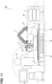
- a treatment system 201 further includes a sheet-shaped pressure sensor 59 in addition to the configuration of the treatment system 1.
- the sheet-shaped pressure sensor 59 has a sheet-shaped form.
- the sheet-shaped pressure sensor 59 includes a plurality of pressure sensors.
- the plurality of pressure sensors are dispersedly arranged on the surface of the sheet-shaped pressure sensor 59.
- the patient 34 lies on the sheet-shaped pressure sensor 59.
- the sheet-shaped pressure sensor 59 outputs the detection results of the plurality of pressure sensors to the control apparatus 3.
- the control apparatus 3 detects the movement of the body of the patient 34 based on the change over time of the detection results of the plurality of pressure sensors.
- the control apparatus 3 detecting the movement of the patient 34 based on the change over time of the detection results of the plurality of pressure sensors with the control apparatus 3 corresponds to the control apparatus 3 detecting the misalignment between the irradiation position F and the target irradiation position T.
- transdermal treatment device instead of the HIFU irradiation unit 33, another transdermal treatment device may be used.
- Other transdermal treatment devices include, for example, a radiant ray irradiation device.
- the target irradiation position T may be estimated by a method of an optical flow.
- a plurality of functions of one element in the above embodiment may be implemented by a plurality of elements, or one function of one element may be implemented by a plurality of elements. Further, a plurality of functions of a plurality of elements may be implemented by one element, or one function implemented by a plurality of elements may be implemented by one element. A part of the configuration of the above embodiments may be omitted. At least a part of the configuration of the above embodiments may be added to or replaced with another configuration of the above embodiments within the scope of appended claims.
- the present disclosure can be realized in various forms, in addition to the control apparatus described above, such as a treatment system including the control apparatus as a component, a program for causing a computer to function as the control apparatus, a non-transitory tangible storage medium such as a semiconductor memory storing the program, or a control method of a treatment system.
- a treatment system including the control apparatus as a component, a program for causing a computer to function as the control apparatus, a non-transitory tangible storage medium such as a semiconductor memory storing the program, or a control method of a treatment system.
Landscapes
- Health & Medical Sciences (AREA)
- Life Sciences & Earth Sciences (AREA)
- Engineering & Computer Science (AREA)
- Surgery (AREA)
- Veterinary Medicine (AREA)
- Nuclear Medicine, Radiotherapy & Molecular Imaging (AREA)
- Public Health (AREA)
- General Health & Medical Sciences (AREA)
- Biomedical Technology (AREA)
- Animal Behavior & Ethology (AREA)
- Medical Informatics (AREA)
- Molecular Biology (AREA)
- Heart & Thoracic Surgery (AREA)
- Radiology & Medical Imaging (AREA)
- Pathology (AREA)
- Physics & Mathematics (AREA)
- Biophysics (AREA)
- Computer Vision & Pattern Recognition (AREA)
- Robotics (AREA)
- Oral & Maxillofacial Surgery (AREA)
- Physiology (AREA)
- Vascular Medicine (AREA)
- Surgical Instruments (AREA)
Description
- The present disclosure relates to a control apparatus.
- There is known a HIFU (High Intensity Focused Ultrasound) treatment system. The HIFU treatment system includes an irradiation unit that irradiates the ultrasound. The ultrasound emitted from the irradiation unit focus on a focal point. Before irradiating the ultrasound, the operator moves the irradiation unit such that the irradiation position of the ultrasound coincides with a target irradiation position. The target irradiation position is an affected portion to be treated. Methods of confirming the irradiation position include a method using an ultrasound diagnostic probe, a method using MRI, and the like. A HIFU treatment system is disclosed in patent document
JP 5998017 B2 - Further, patent document
JP H09 66057 A - Patent document
JP 2000 271136 A - Moreover, patent document
JP 2000 237205 A - [deleted]
- Detailed studies by the inventors have found the following issues. After starting radiating ultrasound, the patient's body may move. When the patient's body moves, the irradiation position is misaligned from the target irradiation position. In this case, the ultrasound is irradiated to a portion other than the target irradiation position.
- The above problem and the resulting object is solved by the subject-matter of
claim 1. Further advantageous configurations of the invention can be drawn from the dependent claims. - According to an explanatory aspect of the present disclosure, it is preferable to provide a control apparatus capable of suppressing irradiation to a portion other than a target irradiation position with a transdermal treatment device even when the patient's body moves during treatment.
- According to an explanatory aspect of the present disclosure, a control apparatus is provided as including a misalignment detection unit and a control unit. The misalignment detection unit is configured to detect a misalignment between an irradiation position of a transdermal treatment device and a target irradiation position. In response to that the misalignment detection unit detects a misalignment, the control unit is configured to stop the irradiation of the transdermal treatment device or to bring the irradiation position closer to the target irradiation position.
- According to the control apparatus of the explanatory aspect of the present disclosure, even if a patient's body moves during treatment, a portion other than the target irradiation position may be suppressed from being irradiated with the transdermal treatment device.
- Here, the reference signs in parentheses described in claims indicate correspondence to the concrete means described in the embodiments, which are examples of the present disclosure. Thus, the technical scope of the present disclosure is not necessarily limited thereto.
- The invention is defined by appended independent claim, preferred embodiments are defined by appended dependent claims.
-
-
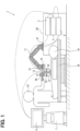
FIG. 1 is an explanatory diagram illustrating a configuration of a treatment system; -
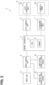
FIG. 2 is a block diagram illustrating an electrical configuration of a treatment system; -
FIG. 3 is a block diagram illustrating a functional configuration of a control apparatus; -
FIG. 4 is a flowchart illustrating a process executed by a control apparatus; -
FIG. 5 is an explanatory diagram illustrating an ultrasound image; -
FIG. 6 is an explanatory diagram illustrating an ultrasound image and a template; -
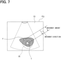
FIG. 7 is an explanatory diagram illustrating an ultrasound image; -
FIG. 8 is a flowchart illustrating a process executed by a control apparatus; -
FIG. 9 is an explanatory diagram illustrating an ultrasound image and a plurality of templates; -
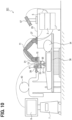
FIG. 10 is an explanatory diagram illustrating a configuration of a treatment system; and -
FIG. 11 is an explanatory diagram illustrating a configuration of a treatment system. - Hereinafter, embodiments of the present disclosure will be described with reference to the drawings.
- The configuration of a
treatment system 1 will be described with reference toFIGS. 1 to 3 . As shown inFIGS. 1 and2 , thetreatment system 1 includes acontrol apparatus 3, aHIFU control unit 5, an ultrasounddiagnostic unit 7, arobot control unit 9, arobot arm 11, atip unit 13, and a monitoring sense offorce sensor 15. The monitoring sense offorce sensor 15 corresponds to a force detection device. - As shown in
FIG. 2 , thecontrol apparatus 3 includes a microcomputer having aCPU 17 and a semiconductor memory such as a RAM or a ROM (hereinafter, referred to as a memory 19). Respective functions of thecontrol apparatus 3 are realized by theCPU 17 executing a program stored in a non-transitory tangible storage medium. In this example, thememory 19 corresponds to a non- transitory tangible storage medium in which the programs are stored. A method corresponding to the program is executed by the execution of the program. Thecontrol apparatus 3 may include one microcomputer, or may include a plurality of microcomputers. - The
control apparatus 3 includes amisalignment detection unit 21, acontrol unit 23, and animage acquisition unit 25, as shown inFIG. 3 . The technique for realizing the functions of each unit included in thecontrol apparatus 3 is not limited to software, and some or all of the functions may be realized using one or more hardware. For example, when the above-described functions may be implemented by an electronic circuit which is hardware, the electronic circuit may be implemented by a digital circuit, an analog circuit, or a combination thereof. - The
HIFU control unit 5 includes an amplifier of aHIFU irradiation unit 33 described later. TheHIFU control unit 5 starts and stops the irradiation of the ultrasound by theHIFU irradiation unit 33. Further, theHIFU control unit 5 adjusts the output of the ultrasound radiated by theHIFU irradiation unit 33. - The ultrasound
diagnostic unit 7 acquires an ultrasound image using adiagnostic probe 35 described later. The ultrasound image is an image representing an inside of the body of thepatient 34. The ultrasounddiagnostic unit 7 has amonitor 8. The ultrasounddiagnostic unit 7 can display an ultrasound image on themonitor 8. - The
robot control unit 9 controls the operation of therobot arm 11. As shown inFIG. 1 , thebase 27 of therobot arm 11 is fixed to a table 29. Thetip unit 13 and the monitoring sense offorce sensor 15 are attached to thetip portion 31 of therobot arm 11. Therobot arm 11 can change the position of thetip unit 13 and the monitoring sense offorce sensor 15 by movement. Therobot arm 11 can press awater bag 37, which will be described later, of thetip unit 13 against the body of thepatient 34. Thepatient 34 is lying on abed 36. The monitoring sense offorce sensor 15 detects a force applied by the body of the patient 34 to thetip unit 13. - The
tip unit 13 includes aHIFU irradiation unit 33, adiagnostic probe 35, awater bag 37, anoperation unit 39, and an operation sense offorce sensor 41. TheHIFU irradiator 33 irradiates the body of the patient 34 with the ultrasound (hereinafter referred to as focused ultrasound) focused on the focal point. TheHIFU irradiation unit 33 and theHIFU control unit 5 correspond to a transdermal treatment device and a focused ultrasound irradiation device. A transdermal treatment device is a device that radiates ultrasound, radiant ray, and the like to the inside of the body of the patient from the outside. The focused ultrasound irradiation device is a device that irradiates ultrasound focused on a focal point inside of the body of the patient from outside. Thewater bag 37 is located between theHIFU irradiation unit 33 and thepatient 34. Thewater bag 37 is pressed against thepatient 34. - The
diagnostic probe 35 creates an ultrasound image representing the inside of the body of the patient 34 using ultrasound. The visual field of the ultrasound image has a fixed positional relationship with the position (hereinafter referred to as irradiation position F) where theHIFU irradiation unit 33 irradiates the focused ultrasound. Thediagnostic probe 35 sends an ultrasound image to the ultrasounddiagnostic unit 7. - The
operation unit 39 is a handle that can be gripped by theoperator 43. Theoperation unit 39 is operated by theoperator 43. The operation sense offorce sensor 41 detects the magnitude and direction of the force applied to theoperation unit 39 by theoperator 43. Therobot control unit 9 operates therobot arm 11 according to the magnitude and direction of the force detected by the operation sense offorce sensor 41. - The processing executed by the
control apparatus 3 will be described with reference toFIGS. 4 to 7 . This processing is executed after theoperator 43 determines a position to be irradiated with the focused ultrasound (hereinafter, referred to as a target irradiation position T) and starts irradiation of the focused ultrasound toward the target irradiation position T. Theoperator 43 can search for the target irradiation position T while viewing the ultrasound image displayed on themonitor 8. The target irradiation position T is at a fixed position with respect to the body of thepatient 34. - In
step 1 ofFIG. 4 , theimage acquisition unit 25 acquires an ultrasound image using the ultrasounddiagnostic unit 7 and thediagnostic probe 35. The ultrasound image acquired here is P(0).FIG. 5 shows an example of the ultrasound image P(0). The ultrasound image P(0) represents a portion of the body of thepatient 34. The irradiation position F is in thevisual field 45 of the ultrasound image P(0). The positional relationship of the irradiation position F with respect to thevisual field 45 is fixed. In the ultrasound image P(0), the position of theHIFU irradiation unit 33 is adjusted such that the target irradiation position T and the irradiation position F match. - In
Step 2, themisalignment detection unit 21 extracts thetemplate 47 from the ultrasound image P(0) as shown inFIG. 6 . Thetemplate 47 is a partial area of the ultrasound image P(0). Themisalignment detection unit 21 extracts thetemplate 47 from a portion excluding the irradiation position F in the ultrasound image P(0). The shape of thetemplate 47 is, for example, a region between theinner circle 49 and theouter circle 51. Thetemplate 47 is at a fixed position with respect to the body of thepatient 34. - In
step 3, theimage acquisition unit 25 sets i to 1. Here, i is a number assigned to the ultrasound image. - In
Step 4, theimage acquisition unit 25 acquires the ultrasound image P(i) using the ultrasounddiagnostic unit 7 and thediagnostic probe 35. The ultrasound image P(i) is the i-th ultrasound image acquired inStep 4. The shape and size of thevisual field 53 of the ultrasound image P(i) are the same as the shape and size of thevisual field 45. - The positional relationship of the irradiation position F with respect to the
visual field 45 and the positional relationship of the irradiation position F with respect to thevisual field 53 are the same. Therefore, when the ultrasound image P(0) and the ultrasound image P(i) are overlapped, the irradiation position F in the ultrasound image P(0) is the same as the irradiation position F in the ultrasound image P(i). - In
step 5, themisalignment detection unit 21 searches the ultrasound image P(i) for a portion (hereinafter referred to as a high correlation portion 55) having a high correlation with thetemplate 47 extracted instep 2.FIG. 7 shows an example of thehigh correlation portion 55. Thehigh correlation portion 55 is, for example, a portion where the correlation coefficient with thetemplate 47 is larger than a preset threshold. Thehigh correlation portion 55 is a portion of the body of the patient 34 that is likely to be the same as the portion represented by thetemplate 47. That is, thehigh correlation portion 55 corresponds to a portion corresponding to thetemplate 47 in the ultrasound image P(i). - If the
misalignment detection unit 21 can find thehigh correlation portion 55 in the ultrasound image P(i), the process proceeds to step 6 and themisalignment detection unit 21 sets thehigh correlation portion 55 in the ultrasound image P(i). If is not found, the process proceeds to step 12. The case where thehigh correlation portion 55 can be found in the ultrasound image P(i) corresponds to the case where the amount of movement of the body of thepatient 34 is small and the target irradiation position T can be tracked. On the other hand, the case where thehigh correlation portion 55 cannot be found in the ultrasound image P(i) corresponds to the case where the amount of movement of the body of thepatient 34 is large and the tracking of the target irradiation position T is impossible. - In step 6, the movement amount and movement direction from the position of the
template 47 in the ultrasound image P(0) to the position of thehigh correlation portion 55 in the ultrasound image P(i) (hereinafter, the movement amount and the movement direction of the high correlation portion 55) are calculated by themisalignment detection unit 21.FIG. 7 shows an example of the movement amount and the movement direction of thehigh correlation portion 55. - The
high correlation portion 55 is a portion of the body of the patient 34 that is likely to be the same as the portion represented by thetemplate 47. The movement amount and the movement direction of thehigh correlation unit 55 are thus the movement amount and the movement direction of the body of the patient 34 from the time when the ultrasound image P(0) is acquired to the time when the ultrasound image P(i) is acquired. Therefore, themisalignment detection unit 21 detects the movement amount and the movement direction of the body of the patient 34 based on the movement amount and the movement direction of thehigh correlation portion 55. - In
Step 7, themisalignment detection unit 21 estimates the target irradiation position T in the ultrasound image P(i). Both (i) the target irradiation position T and (ii) thetemplate 47 or thehigh correlation portion 55 are located at a certain position with respect to thepatient 34. Therefore, the positional relationship between (i) the target irradiation position T and (ii) thetemplate 47 or thehigh correlation portion 55 is always constant. As a result, the movement amount and the movement direction from the target irradiation position T in the ultrasound image P(0) to the target irradiation position T in the ultrasound image P(i) are equal to the movement amount and the movement direction of thehigh correlation portion 55. The target irradiation position T in the ultrasound image P(0) is equal to the irradiation position F as described above. The target irradiation position T in the ultrasound image P(i) is a position moved from the irradiation position F by the movement amount of thehigh correlation portion 55 in the movement direction of thehigh correlation portion 55. - The
misalignment detection unit 21 estimated the target irradiation position T in the ultrasound image P(i) to be located in a position which is moved from the irradiation position F in the movement direction of thehigh correlation portion 55 calculated in step 6 by the movement amount of thehigh correlation portion 55 calculated in step 6.FIG. 7 shows an example of the target irradiation position T in the ultrasound image P(i). - In
step 8, themisalignment detecting unit 21 calculates the amount of misalignment between the target irradiation position T estimated instep 7 and the irradiation position F. Then, themisalignment detecting unit 21 determines whether the amount of the misalignment is smaller than a preset threshold. If the misalignment amount is smaller than the threshold value, the process proceeds to step 10. If the misalignment amount is equal to or greater than the threshold value, the process proceeds to step 9. - In
step 9, thecontrol unit 23 moves the position of theHIFU irradiation unit 33 using therobot control unit 9 and therobot arm 11 so that the irradiation position F and the target irradiation position T match. - In
step 10, thecontrol unit 23 determines whether a preset time has elapsed since the start of the irradiation of the focused ultrasound. If the preset time has elapsed, the process proceeds to step 12. If the preset time has not yet elapsed, the process proceeds to step 11. - In
step 11, thecontrol unit 23 increments the value of i by one. Thereafter, the process proceeds to step 4. - In
Step 12, thecontrol unit 23 stops the irradiation of the focused ultrasound by using theHIFU control unit 5. - The
HIFU control unit 5 irradiates the focused ultrasound with a first output, and then irradiates the focused ultrasound with a second output smaller than the first output. - (1A) The
control apparatus 3 detects a misalignment between the irradiation position F and the target irradiation position T. When detecting the misalignment, thecontrol apparatus 3 brings the irradiation position F closer to the target irradiation position T. Thus, even if the body of the patient 34 moves during the treatment, it is possible to suppress irradiation of a position other than the target irradiation position T with the focused ultrasound. Further, even if the body of the patient 34 moves during the treatment, the target irradiation position T can be irradiated with the focused ultrasound. - (1B) When the movement amount of the
patient 34 is large and the target irradiation position T cannot be tracked, thecontrol apparatus 3 stops the irradiation of the focused ultrasound. Thereby, it is possible to suppress irradiation of a position other than the target irradiation position T with the focused ultrasound. - (1C) The
control apparatus 3 acquires the ultrasound image P(0). In the ultrasound image P(0), the irradiation position F has a fixed positional relationship with thevisual field 45. Thecontrol apparatus 3 extracts thetemplate 47 from the ultrasound image P(0). Thecontrol apparatus 3 searches for thehigh correlation portion 55 in the ultrasound image P(i). Thehigh correlation portion 55 is a portion corresponding to thetemplate 47 in the body of thepatient 34. Thecontrol apparatus 3 detects a movement amount and a movement direction of thehigh correlation portion 55. Thecontrol apparatus 3 detects a misalignment between the irradiation position F and the target irradiation position T based on the movement amount and the movement direction of thehigh correlation portion 55. Therefore, thecontrol apparatus 3 can easily and accurately detect a misalignment between the irradiation position F and the target irradiation position T. - (1D) In the ultrasound images P(0) and P(n), a cavitation occurs near the irradiation position F, and the images change. The
control apparatus 3 extracts thetemplate 47 from the portion excluding the irradiation position F in the ultrasound image P(0). Therefore, thetemplate 47 and thehigh correlation portion 55 hardly include such a cavitation. As a result, thehigh correlation portion 55 can be accurately searched. - (1E) The
control apparatus 3 uses theHIFU control unit 5 to radiate focused ultrasound with a first output, and then radiate focused ultrasound with a second output smaller than the first output. Therefore, the cells in the affected area can be safely destroyed. - Since the basic configuration of a second embodiment is the same as that of the first embodiment, differences will be described below. Note that the same reference signs as those in the first embodiment indicate the same configuration, and refer to the preceding descriptions.
- In the first embodiment described above, the
control apparatus 3 executes the processing shown inFIG. 4 . The second embodiment is different from the first embodiment in that thecontrol apparatus 3 executes the processing shown inFIG. 8 . - The processing executed by the
control apparatus 3 will be described with reference toFIG. 8 . This processing is executed after theoperator 43 determines the target irradiation position T and starts irradiation of the focused ultrasound toward the target irradiation position T. - In
step 21 inFIG. 8 , themisalignment detection unit 21 uses the monitoring sense offorce sensor 15 to detect the magnitude of the force applied by the body of the patient 34 to thetip unit 13. The magnitude of the force detected instep 21 is defined as Xo. - In
step 22, themisalignment detection unit 21 uses the monitoring sense offorce sensor 15 to detect the magnitude of the force applied by the body of the patient 34 to thetip unit 13. The magnitude of the force detected instep 22 is defined as Xa. - In
step 23, themisalignment detection unit 21 determines whether the difference (hereinafter referred to as a force difference ΔX) between the force magnitude Xa obtained in theprevious step 22 and the force magnitude Xo is smaller than a preset threshold value. If the force difference ΔX is smaller than a threshold, the process proceeds to step 24. If the force difference ΔX is equal to or larger than the threshold, the process proceeds to step 25. - When the body of the patient 34 moves, the force difference ΔX increases. Further, when the body of the patient 34 moves, the misalignment between the irradiation position F and the target irradiation position T increases. That is, as the difference ΔX in force is larger, the misalignment between the irradiation position F and the target irradiation position T is larger.
- In
step 23, the difference ΔX in force corresponding to the misalignment between the irradiation position F and the target irradiation position T is detected, and it is determined whether the difference ΔX in force is smaller than a threshold value. This is equivalent to detecting a misalignment between the irradiation position F and the target irradiation position T and determining whether the amount of the misalignment is smaller than a threshold value. - In step 24, the
control unit 23 determines whether a preset time has elapsed since the start of the irradiation of the focused ultrasound. If the preset time has elapsed, the process proceeds to step 25. If the preset time has not yet elapsed, the process proceeds to step 22. - In
step 25, thecontrol unit 23 stops the irradiation of the focused ultrasound by using theHIFU control unit 5. - According to the second embodiment described in detail above, the effect (1E) of the above-described first embodiment is obtained, and further, the following effects are obtained.
- (2A) The
control apparatus 3 detects a misalignment between the irradiation position F and the target irradiation position T. When the amount of misalignment is large, thecontrol apparatus 3 stops the irradiation of the focused ultrasound. Thereby, it is possible to suppress irradiation of a position other than the target irradiation position T with the focused ultrasound. - (2B) The
control apparatus 3 detects the magnitudes Xo and Xa of the force applied by the body of the patient 34 to thetip unit 13. Thecontrol apparatus 3 detects a misalignment between the irradiation position F and the target irradiation position T based on the fluctuation of the detected magnitudes Xo and Xa. Therefore, thecontrol apparatus 3 can easily and accurately detect a misalignment between the irradiation position F and the target irradiation position T. - Although the embodiments of the present disclosure have been described above, the present disclosure is not limited to the embodiments described above, and various modifications can be made to implement the present disclosure.
-
- (1) In the first embodiment, the
misalignment detection unit 21 may extract a plurality oftemplates 47 from the ultrasound image P(0) as shown inFIG. 9 . Each of the plurality oftemplates 47 is extracted from a portion excluding the irradiation position F. - As described in the above, in
step 5, themisalignment detection unit 21 can search for thehigh correlation portion 55 for each of the plurality oftemplates 47. Suppose a case where thehigh correlation portion 55 cannot be found for some of thetemplates 47. In such a case, if thehigh correlation portion 55 is found for a certain number or more of thetemplates 47, themisalignment detection unit 21 performs an affirmative determination instep 5. - In step 6, the movement amount and movement direction of the
high correlation portion 55 can be calculated for each of the plurality ofhigh correlation portions 55. Instep 7, the target irradiation position T in the ultrasound image P(i) can be estimated using, for example, the movement amounts and movement directions of the plurality ofhigh correlation portions 55. - (2) The method by which the
misalignment detection unit 21 detects the misalignment between the irradiation position F and the target irradiation position T may be another method. For example, as shown inFIG. 10 , atreatment system 101 further includes acamera 57 in addition to the configuration of thetreatment system 1. Thecamera 57 repeatedly shoots a range including the patient 34 at predetermined time intervals to create a plurality of images. Thecamera 57 outputs the plurality of created images to thecontrol apparatus 3. Thecontrol apparatus 3 recognizes the body of the patient 34 in each of the plurality of images. Thecontrol apparatus 3 detects the movement of the patient 34 based on the change in the position of the patient 34 in the plurality of images. - When the body of the patient 34 moves, the irradiation position F and the target irradiation position T are misaligned. Therefore, the
control apparatus 3 detecting the movement of the body of the patient 34 based on the change in the position of the body of the patient 34 in the plurality of images corresponds to thecontrol apparatus 3 detecting a misalignment between the irradiation position F and the target irradiation position T. - (3) The method by which the
misalignment detection unit 21 detects the misalignment between the irradiation position F and the target irradiation position T may be another method. For example, as shown inFIG. 11 , atreatment system 201 further includes a sheet-shapedpressure sensor 59 in addition to the configuration of thetreatment system 1. The sheet-shapedpressure sensor 59 has a sheet-shaped form. The sheet-shapedpressure sensor 59 includes a plurality of pressure sensors. The plurality of pressure sensors are dispersedly arranged on the surface of the sheet-shapedpressure sensor 59. The patient 34 lies on the sheet-shapedpressure sensor 59. The sheet-shapedpressure sensor 59 outputs the detection results of the plurality of pressure sensors to thecontrol apparatus 3. Thecontrol apparatus 3 detects the movement of the body of the patient 34 based on the change over time of the detection results of the plurality of pressure sensors. - When the body of the patient 34 moves, the irradiation position F and the target irradiation position T are misaligned. Therefore, the
control apparatus 3 detecting the movement of the patient 34 based on the change over time of the detection results of the plurality of pressure sensors with thecontrol apparatus 3 corresponds to thecontrol apparatus 3 detecting the misalignment between the irradiation position F and the target irradiation position T. - (4) Instead of the
HIFU irradiation unit 33, another transdermal treatment device may be used. Other transdermal treatment devices include, for example, a radiant ray irradiation device. - (5) In the first embodiment, the target irradiation position T may be estimated by a method of an optical flow.
- (6) A plurality of functions of one element in the above embodiment may be implemented by a plurality of elements, or one function of one element may be implemented by a plurality of elements. Further, a plurality of functions of a plurality of elements may be implemented by one element, or one function implemented by a plurality of elements may be implemented by one element. A part of the configuration of the above embodiments may be omitted. At least a part of the configuration of the above embodiments may be added to or replaced with another configuration of the above embodiments within the scope of appended claims.
- (7) The present disclosure can be realized in various forms, in addition to the control apparatus described above, such as a treatment system including the control apparatus as a component, a program for causing a computer to function as the control apparatus, a non-transitory tangible storage medium such as a semiconductor memory storing the program, or a control method of a treatment system.
- The invention is defined by the appended claims.
Claims (3)
- A treatment system (1), comprising:a robot arm (11);a robot control unit (9) configured to control the operation of the robot arm (11);a transdermal treatment device (5, 33) configured to perform an irradiation to an inside of a body of a patient (34) with a tip unit (13) attached to a tip portion (31) of the robot arm (11) controlled by the robot control unit (9);an ultrasound diagnostic unit (7) configured to acquire an ultrasound image using a diagnostic probe (35) of the tip unit (13), wherein the ultrasound image is displayed on a monitor (8) of the ultrasound diagnostic unit (7) so that a target irradiation position (T) to be irradiated by the transdermal treatment device (5, 33) can be determined by an operator based on the ultrasound image;a force sensor (15) configured to detect a force applied by the body of the patient (34) to the tip unit (13), wherein the force sensor (15) is attached to the tip portion (31) of the robot arm (11); anda control apparatus (3) including(i) a misalignment detection unit (21) configured to detect, after the target irradiation position (T) is determined and the irradiation by the transdermal treatment device (5, 33) is started, a misalignment between an irradiation position of the transdermal treatment device (5, 33) and the target irradiation position (T),
wherein the misalignment detection unit (21) is configured toacquire (S21) a first magnitude (Xo) of the force applied to the tip unit (13) of the transdermal treatment device (5, 33) by the body of the patient after the irradiation by the transdermal treatment device (5, 33) is started,acquire (S22) a second magnitude (Xa) of the force applied to the tip unit (13) of the transdermal treatment device (5, 33) by the body of the patient after the first magnitude (Xo) of the force is acquired,perform a determination (S23) to determine whether a force difference (ΔX) between the first magnitude (Xo) of the force and the second magnitude (Xa) of the force is smaller than a preset first threshold value each time the second magnitude (Xa) of the force is acquired, to thereby determine whether or not an amount of the misalignment between the irradiation position of the transdermal treatment device (5, 33) and the target irradiation position is smaller than a preset second threshold value,determine the amount of the misalignment between the irradiation position and the target irradiation position based on the force difference (ΔX) between the first magnitude (Xo) and the second magnitude (Xa) detected by the force sensor (15), consideringthat the amount of the misalignment between the irradiation position and the target irradiation position increases with increasing force difference (ΔX) between the first magnitude (Xo) and the second magnitude (Xa), and(ii) a control unit (23) configured tobring the irradiation position closer to the target irradiation position (T) using the robot control unit (9) and the robot arm (11) in response to the misalignment detection unit (21) determining that the amount of the misalignment is equal to or larger than the second threshold value,determine whether a preset time elapses since the irradiation by the transdermal treatment device (5, 33) is started; andstop the irradiation by the transdermal treatment device (5, 33) in response to determining that the preset time elapses; andwherein the misalignment detection unit (21) is configured to again acquire (S22) the second magnitude (Xa) of the force and perform the determination (S23) in response to determining that the preset time does not elapse; andthe transdermal treatment device (5, 33) includes a control unit (5) and an irradiation unit (33), wherein the control unit (5) starts and stops the irradiation by the irradiation unit (33). - The control apparatus according to claim 1, wherein
the transdermal treatment device is a focused ultrasound irradiation apparatus. - The control apparatus according to claim 2, wherein
the focused ultrasound irradiation apparatus is configured to radiate focused ultrasound with a first output and then radiates focused ultrasound with a second output smaller than the first output.
Applications Claiming Priority (2)
| Application Number | Priority Date | Filing Date | Title |
|---|---|---|---|
| JP2017226981A JP6915869B2 (en) | 2017-11-27 | 2017-11-27 | Control device |
| PCT/JP2018/043040 WO2019103053A1 (en) | 2017-11-27 | 2018-11-21 | Control device |
Publications (3)
| Publication Number | Publication Date |
|---|---|
| EP3718601A1 EP3718601A1 (en) | 2020-10-07 |
| EP3718601A4 EP3718601A4 (en) | 2020-12-30 |
| EP3718601B1 true EP3718601B1 (en) | 2024-06-26 |
Family
ID=66631967
Family Applications (1)
| Application Number | Title | Priority Date | Filing Date |
|---|---|---|---|
| EP18880270.6A Active EP3718601B1 (en) | 2017-11-27 | 2018-11-21 | Control device |
Country Status (4)
| Country | Link |
|---|---|
| US (1) | US11577098B2 (en) |
| EP (1) | EP3718601B1 (en) |
| JP (1) | JP6915869B2 (en) |
| WO (1) | WO2019103053A1 (en) |
Families Citing this family (5)
| Publication number | Priority date | Publication date | Assignee | Title |
|---|---|---|---|---|
| JP6915869B2 (en) | 2017-11-27 | 2021-08-04 | ソニア・セラピューティクス株式会社 | Control device |
| EP3919003B1 (en) * | 2019-01-29 | 2023-11-01 | Kunshan Imagene Medical Co., Ltd. | Ultrasound scanning control method and system, ultrasound scanning device, and storage medium |
| JP7439785B2 (en) * | 2021-03-19 | 2024-02-28 | 株式会社デンソー | Authentication and tracking system |
| JP7137682B1 (en) * | 2021-11-29 | 2022-09-14 | ソニア・セラピューティクス株式会社 | Ultrasound therapy device |
| JP7222562B1 (en) * | 2021-12-07 | 2023-02-15 | ソニア・セラピューティクス株式会社 | HIFU treatment display device |
Citations (1)
| Publication number | Priority date | Publication date | Assignee | Title |
|---|---|---|---|---|
| JP2000237205A (en) * | 1999-02-17 | 2000-09-05 | Toshiba Corp | Ultrasound therapy equipment |
Family Cites Families (14)
| Publication number | Priority date | Publication date | Assignee | Title |
|---|---|---|---|---|
| JPH0576538A (en) * | 1991-09-13 | 1993-03-30 | Shimadzu Corp | Ultrasonic treating device |
| JPH0966057A (en) * | 1995-09-01 | 1997-03-11 | Toshiba Corp | Ultrasound therapy equipment |
| JPH09248213A (en) | 1996-01-12 | 1997-09-22 | Hoomaa Ion Kenkyusho:Kk | Cosmetic and leaning device applying ultrasonic |
| JP2000271136A (en) * | 1999-03-25 | 2000-10-03 | Toshiba Corp | Ultrasound therapy device and ultrasound therapy device control method |
| EP1699354A4 (en) * | 2003-12-30 | 2011-01-05 | Medicis Technologies Corp | Systems and methods for the destruction of adipose tissue |
| JP4459979B2 (en) | 2007-05-09 | 2010-04-28 | 株式会社日立メディコ | Ultrasonic therapy device |
| JP5311392B2 (en) * | 2009-03-11 | 2013-10-09 | 国立大学法人 東京大学 | In vivo stone detection device |
| JP2013123605A (en) * | 2011-12-16 | 2013-06-24 | Seiko Epson Corp | Ultrasonic diagnostic apparatus and method for controlling the same |
| JP5998017B2 (en) * | 2012-11-09 | 2016-09-28 | 株式会社日立製作所 | Ultrasonic therapy apparatus and ultrasonic therapy support system |
| JP6065103B2 (en) * | 2013-03-27 | 2017-01-25 | 株式会社島津製作所 | X-ray fluoroscope |
| JP2017023339A (en) | 2015-07-21 | 2017-02-02 | 株式会社デンソー | Medical practice support device |
| JP6650474B2 (en) * | 2016-02-09 | 2020-02-19 | 株式会社Murakumo | Ultrasonic oscillation device and related method and program |
| FR3072577B1 (en) * | 2017-10-23 | 2019-09-27 | Cardiawave Sa | APPARATUS FOR TREATING VASCULAR THROMBOSIS BY ULTRASOUND |
| JP6915869B2 (en) | 2017-11-27 | 2021-08-04 | ソニア・セラピューティクス株式会社 | Control device |
-
2017
- 2017-11-27 JP JP2017226981A patent/JP6915869B2/en active Active
-
2018
- 2018-11-21 WO PCT/JP2018/043040 patent/WO2019103053A1/en not_active Ceased
- 2018-11-21 EP EP18880270.6A patent/EP3718601B1/en active Active
-
2020
- 2020-05-12 US US16/872,847 patent/US11577098B2/en active Active
Patent Citations (1)
| Publication number | Priority date | Publication date | Assignee | Title |
|---|---|---|---|---|
| JP2000237205A (en) * | 1999-02-17 | 2000-09-05 | Toshiba Corp | Ultrasound therapy equipment |
Also Published As
| Publication number | Publication date |
|---|---|
| JP6915869B2 (en) | 2021-08-04 |
| EP3718601A1 (en) | 2020-10-07 |
| WO2019103053A1 (en) | 2019-05-31 |
| US11577098B2 (en) | 2023-02-14 |
| EP3718601A4 (en) | 2020-12-30 |
| US20200269074A1 (en) | 2020-08-27 |
| JP2019093002A (en) | 2019-06-20 |
Similar Documents
| Publication | Publication Date | Title |
|---|---|---|
| US11577098B2 (en) | Control apparatus | |
| JP7178009B2 (en) | MEDICAL DEVICE, METHOD OF CONTROLLING MEDICAL DEVICE, AND PROGRAM | |
| CN105848717B (en) | Method for handling the device of tissue and for operating the device | |
| WO2005120373A1 (en) | Ultrasonic curing device | |
| US20160114194A1 (en) | Optimized therapeutic energy delivery | |
| JP2011507585A5 (en) | ||
| US12458449B2 (en) | Automatic ablation antenna segmentation from CT image | |
| CN108136205B (en) | A system that supports the disposition of objects | |
| CN102526899B (en) | Focused ultrasonic therapy system and monitoring method thereof | |
| US7916835B2 (en) | X-ray imaging apparatus, control method for X-ray imaging apparatus, program, and storage medium | |
| US20170150942A1 (en) | Ultrasonic diagnostic apparatus | |
| JP2019165840A (en) | Treatment device | |
| JP4505639B2 (en) | Moving body tracking irradiation apparatus and program | |
| JP2020062205A (en) | Treatment system | |
| US11282244B2 (en) | Moving body tracking apparatus, radiation therapy system including the same, program, and moving body tracking method | |
| US20230233874A1 (en) | A photobiomodulation therapy low-level laser targeting system | |
| CN118354820B (en) | Display device for HIFU treatment | |
| JP7092346B2 (en) | Image control device | |
| KR20140079184A (en) | Treatment apparatus using ultrasonic wave and treatment method thereof | |
| JP7320297B2 (en) | HIFU irradiation equipment | |
| JP2003199760A (en) | Ultrasonic therapeutic device | |
| US20230293199A1 (en) | Determining a movement of an object, and therapy apparatus | |
| CN116999726A (en) | Micro-focusing ultrasonic diagnosis and treatment equipment and method | |
| CN119770163A (en) | A microwave focused thermal therapy device and system for tumor treatment | |
| JP2020032080A (en) | Controller |
Legal Events
| Date | Code | Title | Description |
|---|---|---|---|
| STAA | Information on the status of an ep patent application or granted ep patent |
Free format text: STATUS: THE INTERNATIONAL PUBLICATION HAS BEEN MADE |
|
| PUAI | Public reference made under article 153(3) epc to a published international application that has entered the european phase |
Free format text: ORIGINAL CODE: 0009012 |
|
| STAA | Information on the status of an ep patent application or granted ep patent |
Free format text: STATUS: REQUEST FOR EXAMINATION WAS MADE |
|
| 17P | Request for examination filed |
Effective date: 20200428 |
|
| AK | Designated contracting states |
Kind code of ref document: A1 Designated state(s): AL AT BE BG CH CY CZ DE DK EE ES FI FR GB GR HR HU IE IS IT LI LT LU LV MC MK MT NL NO PL PT RO RS SE SI SK SM TR |
|
| AX | Request for extension of the european patent |
Extension state: BA ME |
|
| STAA | Information on the status of an ep patent application or granted ep patent |
Free format text: STATUS: EXAMINATION IS IN PROGRESS |
|
| A4 | Supplementary search report drawn up and despatched |
Effective date: 20201130 |
|
| RIC1 | Information provided on ipc code assigned before grant |
Ipc: A61B 8/00 20060101ALI20201123BHEP Ipc: A61N 7/02 20060101ALI20201123BHEP Ipc: A61B 8/08 20060101AFI20201123BHEP Ipc: A61N 7/00 20060101ALI20201123BHEP |
|
| 17Q | First examination report despatched |
Effective date: 20201222 |
|
| DAV | Request for validation of the european patent (deleted) | ||
| DAX | Request for extension of the european patent (deleted) | ||
| RAP1 | Party data changed (applicant data changed or rights of an application transferred) |
Owner name: SONIRE THERAPEUTICS INC. |
|
| RAP3 | Party data changed (applicant data changed or rights of an application transferred) |
Owner name: SONIRE THERAPEUTICS INC. |
|
| RIC1 | Information provided on ipc code assigned before grant |
Ipc: A61N 7/02 20060101ALI20220712BHEP Ipc: A61N 7/00 20060101ALI20220712BHEP Ipc: A61B 8/00 20060101ALI20220712BHEP Ipc: A61B 8/08 20060101AFI20220712BHEP |
|
| REG | Reference to a national code |
Ref country code: DE Free format text: PREVIOUS MAIN CLASS: A61N0007000000 Ref country code: DE Ref legal event code: R079 Ref document number: 602018071132 Country of ref document: DE Free format text: PREVIOUS MAIN CLASS: A61N0007000000 Ipc: A61B0008080000 |
|
| GRAP | Despatch of communication of intention to grant a patent |
Free format text: ORIGINAL CODE: EPIDOSNIGR1 |
|
| STAA | Information on the status of an ep patent application or granted ep patent |
Free format text: STATUS: GRANT OF PATENT IS INTENDED |
|
| RIC1 | Information provided on ipc code assigned before grant |
Ipc: A61N 7/00 20060101ALN20240115BHEP Ipc: A61B 90/00 20160101ALN20240115BHEP Ipc: A61N 7/02 20060101ALI20240115BHEP Ipc: A61B 8/00 20060101ALI20240115BHEP Ipc: A61B 8/08 20060101AFI20240115BHEP |
|
| INTG | Intention to grant announced |
Effective date: 20240130 |
|
| GRAS | Grant fee paid |
Free format text: ORIGINAL CODE: EPIDOSNIGR3 |
|
| GRAA | (expected) grant |
Free format text: ORIGINAL CODE: 0009210 |
|
| STAA | Information on the status of an ep patent application or granted ep patent |
Free format text: STATUS: THE PATENT HAS BEEN GRANTED |
|
| RAP3 | Party data changed (applicant data changed or rights of an application transferred) |
Owner name: SONIRE THERAPEUTICS INC. |
|
| AK | Designated contracting states |
Kind code of ref document: B1 Designated state(s): AL AT BE BG CH CY CZ DE DK EE ES FI FR GB GR HR HU IE IS IT LI LT LU LV MC MK MT NL NO PL PT RO RS SE SI SK SM TR |
|
| REG | Reference to a national code |
Ref country code: GB Ref legal event code: FG4D |
|
| REG | Reference to a national code |
Ref country code: CH Ref legal event code: EP |
|
| REG | Reference to a national code |
Ref country code: DE Ref legal event code: R096 Ref document number: 602018071132 Country of ref document: DE |
|
| PG25 | Lapsed in a contracting state [announced via postgrant information from national office to epo] |
Ref country code: BG Free format text: LAPSE BECAUSE OF FAILURE TO SUBMIT A TRANSLATION OF THE DESCRIPTION OR TO PAY THE FEE WITHIN THE PRESCRIBED TIME-LIMIT Effective date: 20240626 |
|
| PG25 | Lapsed in a contracting state [announced via postgrant information from national office to epo] |
Ref country code: HR Free format text: LAPSE BECAUSE OF FAILURE TO SUBMIT A TRANSLATION OF THE DESCRIPTION OR TO PAY THE FEE WITHIN THE PRESCRIBED TIME-LIMIT Effective date: 20240626 Ref country code: FI Free format text: LAPSE BECAUSE OF FAILURE TO SUBMIT A TRANSLATION OF THE DESCRIPTION OR TO PAY THE FEE WITHIN THE PRESCRIBED TIME-LIMIT Effective date: 20240626 |
|
| REG | Reference to a national code |
Ref country code: LT Ref legal event code: MG9D |
|
| PG25 | Lapsed in a contracting state [announced via postgrant information from national office to epo] |
Ref country code: GR Free format text: LAPSE BECAUSE OF FAILURE TO SUBMIT A TRANSLATION OF THE DESCRIPTION OR TO PAY THE FEE WITHIN THE PRESCRIBED TIME-LIMIT Effective date: 20240927 |
|
| PG25 | Lapsed in a contracting state [announced via postgrant information from national office to epo] |
Ref country code: LV Free format text: LAPSE BECAUSE OF FAILURE TO SUBMIT A TRANSLATION OF THE DESCRIPTION OR TO PAY THE FEE WITHIN THE PRESCRIBED TIME-LIMIT Effective date: 20240626 |
|
| REG | Reference to a national code |
Ref country code: NL Ref legal event code: MP Effective date: 20240626 |
|
| PG25 | Lapsed in a contracting state [announced via postgrant information from national office to epo] |
Ref country code: NO Free format text: LAPSE BECAUSE OF FAILURE TO SUBMIT A TRANSLATION OF THE DESCRIPTION OR TO PAY THE FEE WITHIN THE PRESCRIBED TIME-LIMIT Effective date: 20240926 Ref country code: LV Free format text: LAPSE BECAUSE OF FAILURE TO SUBMIT A TRANSLATION OF THE DESCRIPTION OR TO PAY THE FEE WITHIN THE PRESCRIBED TIME-LIMIT Effective date: 20240626 Ref country code: HR Free format text: LAPSE BECAUSE OF FAILURE TO SUBMIT A TRANSLATION OF THE DESCRIPTION OR TO PAY THE FEE WITHIN THE PRESCRIBED TIME-LIMIT Effective date: 20240626 Ref country code: GR Free format text: LAPSE BECAUSE OF FAILURE TO SUBMIT A TRANSLATION OF THE DESCRIPTION OR TO PAY THE FEE WITHIN THE PRESCRIBED TIME-LIMIT Effective date: 20240927 Ref country code: FI Free format text: LAPSE BECAUSE OF FAILURE TO SUBMIT A TRANSLATION OF THE DESCRIPTION OR TO PAY THE FEE WITHIN THE PRESCRIBED TIME-LIMIT Effective date: 20240626 Ref country code: BG Free format text: LAPSE BECAUSE OF FAILURE TO SUBMIT A TRANSLATION OF THE DESCRIPTION OR TO PAY THE FEE WITHIN THE PRESCRIBED TIME-LIMIT Effective date: 20240626 Ref country code: RS Free format text: LAPSE BECAUSE OF FAILURE TO SUBMIT A TRANSLATION OF THE DESCRIPTION OR TO PAY THE FEE WITHIN THE PRESCRIBED TIME-LIMIT Effective date: 20240926 |
|
| PG25 | Lapsed in a contracting state [announced via postgrant information from national office to epo] |
Ref country code: NL Free format text: LAPSE BECAUSE OF FAILURE TO SUBMIT A TRANSLATION OF THE DESCRIPTION OR TO PAY THE FEE WITHIN THE PRESCRIBED TIME-LIMIT Effective date: 20240626 |
|
| REG | Reference to a national code |
Ref country code: AT Ref legal event code: MK05 Ref document number: 1697018 Country of ref document: AT Kind code of ref document: T Effective date: 20240626 |
|
| PG25 | Lapsed in a contracting state [announced via postgrant information from national office to epo] |
Ref country code: NL Free format text: LAPSE BECAUSE OF FAILURE TO SUBMIT A TRANSLATION OF THE DESCRIPTION OR TO PAY THE FEE WITHIN THE PRESCRIBED TIME-LIMIT Effective date: 20240626 |
|
| PG25 | Lapsed in a contracting state [announced via postgrant information from national office to epo] |
Ref country code: PT Free format text: LAPSE BECAUSE OF FAILURE TO SUBMIT A TRANSLATION OF THE DESCRIPTION OR TO PAY THE FEE WITHIN THE PRESCRIBED TIME-LIMIT Effective date: 20241028 |
|
| PG25 | Lapsed in a contracting state [announced via postgrant information from national office to epo] |
Ref country code: PT Free format text: LAPSE BECAUSE OF FAILURE TO SUBMIT A TRANSLATION OF THE DESCRIPTION OR TO PAY THE FEE WITHIN THE PRESCRIBED TIME-LIMIT Effective date: 20241028 |
|
| PG25 | Lapsed in a contracting state [announced via postgrant information from national office to epo] |
Ref country code: PL Free format text: LAPSE BECAUSE OF FAILURE TO SUBMIT A TRANSLATION OF THE DESCRIPTION OR TO PAY THE FEE WITHIN THE PRESCRIBED TIME-LIMIT Effective date: 20240626 |
|
| PG25 | Lapsed in a contracting state [announced via postgrant information from national office to epo] |
Ref country code: EE Free format text: LAPSE BECAUSE OF FAILURE TO SUBMIT A TRANSLATION OF THE DESCRIPTION OR TO PAY THE FEE WITHIN THE PRESCRIBED TIME-LIMIT Effective date: 20240626 |
|
| PG25 | Lapsed in a contracting state [announced via postgrant information from national office to epo] |
Ref country code: AT Free format text: LAPSE BECAUSE OF FAILURE TO SUBMIT A TRANSLATION OF THE DESCRIPTION OR TO PAY THE FEE WITHIN THE PRESCRIBED TIME-LIMIT Effective date: 20240626 Ref country code: IS Free format text: LAPSE BECAUSE OF FAILURE TO SUBMIT A TRANSLATION OF THE DESCRIPTION OR TO PAY THE FEE WITHIN THE PRESCRIBED TIME-LIMIT Effective date: 20241026 |
|
| PG25 | Lapsed in a contracting state [announced via postgrant information from national office to epo] |
Ref country code: CZ Free format text: LAPSE BECAUSE OF FAILURE TO SUBMIT A TRANSLATION OF THE DESCRIPTION OR TO PAY THE FEE WITHIN THE PRESCRIBED TIME-LIMIT Effective date: 20240626 |
|
| PG25 | Lapsed in a contracting state [announced via postgrant information from national office to epo] |
Ref country code: RO Free format text: LAPSE BECAUSE OF FAILURE TO SUBMIT A TRANSLATION OF THE DESCRIPTION OR TO PAY THE FEE WITHIN THE PRESCRIBED TIME-LIMIT Effective date: 20240626 Ref country code: SK Free format text: LAPSE BECAUSE OF FAILURE TO SUBMIT A TRANSLATION OF THE DESCRIPTION OR TO PAY THE FEE WITHIN THE PRESCRIBED TIME-LIMIT Effective date: 20240626 |
|
| PG25 | Lapsed in a contracting state [announced via postgrant information from national office to epo] |
Ref country code: ES Free format text: LAPSE BECAUSE OF FAILURE TO SUBMIT A TRANSLATION OF THE DESCRIPTION OR TO PAY THE FEE WITHIN THE PRESCRIBED TIME-LIMIT Effective date: 20240626 Ref country code: SM Free format text: LAPSE BECAUSE OF FAILURE TO SUBMIT A TRANSLATION OF THE DESCRIPTION OR TO PAY THE FEE WITHIN THE PRESCRIBED TIME-LIMIT Effective date: 20240626 |
|
| PG25 | Lapsed in a contracting state [announced via postgrant information from national office to epo] |
Ref country code: SM Free format text: LAPSE BECAUSE OF FAILURE TO SUBMIT A TRANSLATION OF THE DESCRIPTION OR TO PAY THE FEE WITHIN THE PRESCRIBED TIME-LIMIT Effective date: 20240626 Ref country code: SK Free format text: LAPSE BECAUSE OF FAILURE TO SUBMIT A TRANSLATION OF THE DESCRIPTION OR TO PAY THE FEE WITHIN THE PRESCRIBED TIME-LIMIT Effective date: 20240626 Ref country code: RO Free format text: LAPSE BECAUSE OF FAILURE TO SUBMIT A TRANSLATION OF THE DESCRIPTION OR TO PAY THE FEE WITHIN THE PRESCRIBED TIME-LIMIT Effective date: 20240626 Ref country code: PL Free format text: LAPSE BECAUSE OF FAILURE TO SUBMIT A TRANSLATION OF THE DESCRIPTION OR TO PAY THE FEE WITHIN THE PRESCRIBED TIME-LIMIT Effective date: 20240626 Ref country code: IS Free format text: LAPSE BECAUSE OF FAILURE TO SUBMIT A TRANSLATION OF THE DESCRIPTION OR TO PAY THE FEE WITHIN THE PRESCRIBED TIME-LIMIT Effective date: 20241026 Ref country code: ES Free format text: LAPSE BECAUSE OF FAILURE TO SUBMIT A TRANSLATION OF THE DESCRIPTION OR TO PAY THE FEE WITHIN THE PRESCRIBED TIME-LIMIT Effective date: 20240626 Ref country code: EE Free format text: LAPSE BECAUSE OF FAILURE TO SUBMIT A TRANSLATION OF THE DESCRIPTION OR TO PAY THE FEE WITHIN THE PRESCRIBED TIME-LIMIT Effective date: 20240626 Ref country code: CZ Free format text: LAPSE BECAUSE OF FAILURE TO SUBMIT A TRANSLATION OF THE DESCRIPTION OR TO PAY THE FEE WITHIN THE PRESCRIBED TIME-LIMIT Effective date: 20240626 Ref country code: AT Free format text: LAPSE BECAUSE OF FAILURE TO SUBMIT A TRANSLATION OF THE DESCRIPTION OR TO PAY THE FEE WITHIN THE PRESCRIBED TIME-LIMIT Effective date: 20240626 |
|
| PG25 | Lapsed in a contracting state [announced via postgrant information from national office to epo] |
Ref country code: IT Free format text: LAPSE BECAUSE OF FAILURE TO SUBMIT A TRANSLATION OF THE DESCRIPTION OR TO PAY THE FEE WITHIN THE PRESCRIBED TIME-LIMIT Effective date: 20240626 |
|
| REG | Reference to a national code |
Ref country code: DE Ref legal event code: R097 Ref document number: 602018071132 Country of ref document: DE |
|
| PG25 | Lapsed in a contracting state [announced via postgrant information from national office to epo] |
Ref country code: DK Free format text: LAPSE BECAUSE OF FAILURE TO SUBMIT A TRANSLATION OF THE DESCRIPTION OR TO PAY THE FEE WITHIN THE PRESCRIBED TIME-LIMIT Effective date: 20240626 |
|
| PLBE | No opposition filed within time limit |
Free format text: ORIGINAL CODE: 0009261 |
|
| STAA | Information on the status of an ep patent application or granted ep patent |
Free format text: STATUS: NO OPPOSITION FILED WITHIN TIME LIMIT |
|
| REG | Reference to a national code |
Ref country code: DE Ref legal event code: R119 Ref document number: 602018071132 Country of ref document: DE |
|
| 26N | No opposition filed |
Effective date: 20250327 |
|
| REG | Reference to a national code |
Ref country code: CH Ref legal event code: PL |
|
| PG25 | Lapsed in a contracting state [announced via postgrant information from national office to epo] |
Ref country code: MC Free format text: LAPSE BECAUSE OF FAILURE TO SUBMIT A TRANSLATION OF THE DESCRIPTION OR TO PAY THE FEE WITHIN THE PRESCRIBED TIME-LIMIT Effective date: 20240626 |
|
| PG25 | Lapsed in a contracting state [announced via postgrant information from national office to epo] |
Ref country code: LU Free format text: LAPSE BECAUSE OF NON-PAYMENT OF DUE FEES Effective date: 20241121 |
|
| REG | Reference to a national code |
Ref country code: CH Ref legal event code: PL |
|
| GBPC | Gb: european patent ceased through non-payment of renewal fee |
Effective date: 20241121 |
|
| PG25 | Lapsed in a contracting state [announced via postgrant information from national office to epo] |
Ref country code: CH Free format text: LAPSE BECAUSE OF NON-PAYMENT OF DUE FEES Effective date: 20241130 |
|
| REG | Reference to a national code |
Ref country code: BE Ref legal event code: MM Effective date: 20241130 |
|
| PG25 | Lapsed in a contracting state [announced via postgrant information from national office to epo] |
Ref country code: SE Free format text: LAPSE BECAUSE OF FAILURE TO SUBMIT A TRANSLATION OF THE DESCRIPTION OR TO PAY THE FEE WITHIN THE PRESCRIBED TIME-LIMIT Effective date: 20240626 |
|
| PG25 | Lapsed in a contracting state [announced via postgrant information from national office to epo] |
Ref country code: DE Free format text: LAPSE BECAUSE OF NON-PAYMENT OF DUE FEES Effective date: 20250603 |
|
| PG25 | Lapsed in a contracting state [announced via postgrant information from national office to epo] |
Ref country code: GB Free format text: LAPSE BECAUSE OF NON-PAYMENT OF DUE FEES Effective date: 20241121 Ref country code: BE Free format text: LAPSE BECAUSE OF NON-PAYMENT OF DUE FEES Effective date: 20241130 |
|
| PG25 | Lapsed in a contracting state [announced via postgrant information from national office to epo] |
Ref country code: IE Free format text: LAPSE BECAUSE OF NON-PAYMENT OF DUE FEES Effective date: 20241121 |
|
| PGFP | Annual fee paid to national office [announced via postgrant information from national office to epo] |
Ref country code: FR Payment date: 20251124 Year of fee payment: 8 |
|
| PG25 | Lapsed in a contracting state [announced via postgrant information from national office to epo] |
Ref country code: HU Free format text: LAPSE BECAUSE OF FAILURE TO SUBMIT A TRANSLATION OF THE DESCRIPTION OR TO PAY THE FEE WITHIN THE PRESCRIBED TIME-LIMIT; INVALID AB INITIO Effective date: 20181121 |
|
| PG25 | Lapsed in a contracting state [announced via postgrant information from national office to epo] |
Ref country code: CY Free format text: LAPSE BECAUSE OF FAILURE TO SUBMIT A TRANSLATION OF THE DESCRIPTION OR TO PAY THE FEE WITHIN THE PRESCRIBED TIME-LIMIT; INVALID AB INITIO Effective date: 20181121 |