EP3718402A1 - Organ container - Google Patents
Organ container Download PDFInfo
- Publication number
- EP3718402A1 EP3718402A1 EP18884777.6A EP18884777A EP3718402A1 EP 3718402 A1 EP3718402 A1 EP 3718402A1 EP 18884777 A EP18884777 A EP 18884777A EP 3718402 A1 EP3718402 A1 EP 3718402A1
- Authority
- EP
- European Patent Office
- Prior art keywords
- film
- organ
- organ container
- container according
- liver
- Prior art date
- Legal status (The legal status is an assumption and is not a legal conclusion. Google has not performed a legal analysis and makes no representation as to the accuracy of the status listed.)
- Withdrawn
Links
Images



Classifications
-
- C—CHEMISTRY; METALLURGY
- C12—BIOCHEMISTRY; BEER; SPIRITS; WINE; VINEGAR; MICROBIOLOGY; ENZYMOLOGY; MUTATION OR GENETIC ENGINEERING
- C12M—APPARATUS FOR ENZYMOLOGY OR MICROBIOLOGY; APPARATUS FOR CULTURING MICROORGANISMS FOR PRODUCING BIOMASS, FOR GROWING CELLS OR FOR OBTAINING FERMENTATION OR METABOLIC PRODUCTS, i.e. BIOREACTORS OR FERMENTERS
- C12M21/00—Bioreactors or fermenters specially adapted for specific uses
- C12M21/08—Bioreactors or fermenters specially adapted for specific uses for producing artificial tissue or for ex-vivo cultivation of tissue
-
- A—HUMAN NECESSITIES
- A01—AGRICULTURE; FORESTRY; ANIMAL HUSBANDRY; HUNTING; TRAPPING; FISHING
- A01N—PRESERVATION OF BODIES OF HUMANS OR ANIMALS OR PLANTS OR PARTS THEREOF; BIOCIDES, e.g. AS DISINFECTANTS, AS PESTICIDES OR AS HERBICIDES; PEST REPELLANTS OR ATTRACTANTS; PLANT GROWTH REGULATORS
- A01N1/00—Preservation of bodies of humans or animals, or parts thereof
- A01N1/10—Preservation of living parts
-
- A—HUMAN NECESSITIES
- A01—AGRICULTURE; FORESTRY; ANIMAL HUSBANDRY; HUNTING; TRAPPING; FISHING
- A01N—PRESERVATION OF BODIES OF HUMANS OR ANIMALS OR PLANTS OR PARTS THEREOF; BIOCIDES, e.g. AS DISINFECTANTS, AS PESTICIDES OR AS HERBICIDES; PEST REPELLANTS OR ATTRACTANTS; PLANT GROWTH REGULATORS
- A01N1/00—Preservation of bodies of humans or animals, or parts thereof
- A01N1/10—Preservation of living parts
- A01N1/14—Mechanical aspects of preservation; Apparatus or containers therefor
- A01N1/142—Apparatus
- A01N1/143—Apparatus for organ perfusion
-
- C—CHEMISTRY; METALLURGY
- C12—BIOCHEMISTRY; BEER; SPIRITS; WINE; VINEGAR; MICROBIOLOGY; ENZYMOLOGY; MUTATION OR GENETIC ENGINEERING
- C12M—APPARATUS FOR ENZYMOLOGY OR MICROBIOLOGY; APPARATUS FOR CULTURING MICROORGANISMS FOR PRODUCING BIOMASS, FOR GROWING CELLS OR FOR OBTAINING FERMENTATION OR METABOLIC PRODUCTS, i.e. BIOREACTORS OR FERMENTERS
- C12M23/00—Constructional details, e.g. recesses, hinges
- C12M23/02—Form or structure of the vessel
- C12M23/06—Tubular
-
- C—CHEMISTRY; METALLURGY
- C12—BIOCHEMISTRY; BEER; SPIRITS; WINE; VINEGAR; MICROBIOLOGY; ENZYMOLOGY; MUTATION OR GENETIC ENGINEERING
- C12M—APPARATUS FOR ENZYMOLOGY OR MICROBIOLOGY; APPARATUS FOR CULTURING MICROORGANISMS FOR PRODUCING BIOMASS, FOR GROWING CELLS OR FOR OBTAINING FERMENTATION OR METABOLIC PRODUCTS, i.e. BIOREACTORS OR FERMENTERS
- C12M23/00—Constructional details, e.g. recesses, hinges
- C12M23/02—Form or structure of the vessel
- C12M23/14—Bags
-
- C—CHEMISTRY; METALLURGY
- C12—BIOCHEMISTRY; BEER; SPIRITS; WINE; VINEGAR; MICROBIOLOGY; ENZYMOLOGY; MUTATION OR GENETIC ENGINEERING
- C12M—APPARATUS FOR ENZYMOLOGY OR MICROBIOLOGY; APPARATUS FOR CULTURING MICROORGANISMS FOR PRODUCING BIOMASS, FOR GROWING CELLS OR FOR OBTAINING FERMENTATION OR METABOLIC PRODUCTS, i.e. BIOREACTORS OR FERMENTERS
- C12M23/00—Constructional details, e.g. recesses, hinges
- C12M23/26—Constructional details, e.g. recesses, hinges flexible
-
- C—CHEMISTRY; METALLURGY
- C12—BIOCHEMISTRY; BEER; SPIRITS; WINE; VINEGAR; MICROBIOLOGY; ENZYMOLOGY; MUTATION OR GENETIC ENGINEERING
- C12M—APPARATUS FOR ENZYMOLOGY OR MICROBIOLOGY; APPARATUS FOR CULTURING MICROORGANISMS FOR PRODUCING BIOMASS, FOR GROWING CELLS OR FOR OBTAINING FERMENTATION OR METABOLIC PRODUCTS, i.e. BIOREACTORS OR FERMENTERS
- C12M23/00—Constructional details, e.g. recesses, hinges
- C12M23/38—Caps; Covers; Plugs; Pouring means
Definitions
- the present invention relates to an organ container that accommodates an organ.
- organ transplant operations such as liver transplantation
- an organ is temporarily preserved outside the body during the period from when the organ is removed from the donor to when the organ is transplanted into the recipient.
- the organ is connected to tubes so that a preservation solution is perfused through the organ in order to prevent the organ from becoming ischemic.
- the organ also needs to be transported while being preserved.
- Patent Document 1 describes a conventional device for preserving an organ outside the body.
- Patent Document 1 Japanese Patent Application Laid-Open No. H3-151303
- Patent Document 1 uses a hammock made of hydrophobic cloth to hold an organ.
- merely placing the organ on the hammock as in Patent Document 1 increases the likelihood of the position of the organ being shifted relative to the hammock. It is thus difficult to transport the organ from the donor to the recipient without damage.
- the present invention has been made in view of such circumstances, and it is an object of the present invention to provide an organ container that is capable of preserving an organ while allowing a liquid to be perfused through the organ and that is also capable of reducing the occurrence of a shift in the position of the organ and damage to the organ.
- a first aspect of the present invention is an organ container for containing an organ, and includes a flexible film that holds the organ, an opening and closing part that opens and closes an edge of the film, and a tube holder that holds a tube extending between the organ in the film and an outside of the film.
- a second aspect of the present invention is the organ container according to the first aspect, wherein the film incudes a sheet-like first film that covers a lower part of the organ, and a sheet-like second film that covers an upper part of the organ, and the organ is sandwiched and held between the first film and the second film.
- a third aspect of the present invention is the organ container according to the second aspect, wherein the opening and closing part includes a ring-shaped lower frame that supports peripheral portions of the first film and the second film from an underside, the peripheral portions overlapping each other, and a ring-shaped upper frame that sandwiches the peripheral portions of the first film and the second film with the lower frame.
- a fourth aspect of the present invention is the organ container according to the third aspect.
- This organ container further includes a locking part that locks and fixes the lower frame and the upper frame to each other by bringing the lower frame and the upper frame close to each other.
- a fifth aspect of the present invention is the organ container according to the third or fourth aspect, wherein the tube holder has a groove provided in at least one of an upper face of the lower frame and a lower face of the upper frame, and the tube is fitted in the groove.
- a sixth aspect of the present invention is the organ container according to the fifth aspect, wherein the tube holder has a plurality of grooves, each of which is the groove, and the plurality of grooves are provided at intervals in a circumferential direction.
- a seventh aspect of the present invention is the organ container according to the first aspect.
- This organ container includes a pouch-like film bag formed of the film. The organ is accommodated in the film bag.
- An eighth aspect of the present invention is the organ container according to the seventh aspect, wherein the opening and closing part is an openable and closable chuck provided at an opening of the film bag.
- a ninth aspect of the present invention is the organ container according to the eighth aspect, wherein the chuck includes a pair of chuck members capable of becoming in intimate contact with and separated from each other, the tube holder has a groove provided in at least one of the pair of chuck members, and the tube is fitted in the groove.
- a tenth aspect of the present invention is the organ container according to the seventh aspect, wherein the opening and closing part includes a drawstring capable of tightening and loosening the opening of the film bag.
- An eleventh aspect of the present invention is the organ container according to any one of the first to tenth aspects, wherein the film is made of a resin.
- the organ it is possible to hold the organ while allowing a liquid to be perfused through the organ via the tube. It is also possible to reduce the movement of the organ relative to the organ container and to reduce damage to the organ.
- using the separate first and second films allows these films to become wide open vertically. This facilitates putting the organ into and out of the organ container.
- the lower frame and the upper frame can be fixed to each other by one touch without use of a fastening device such as a screw.
- the tube can be fixed in any of the grooves prepared in advance.
- the number of components of the organ container can be reduced.
- donors and recipients may be humans, or may be non-human animals. That is, in the present application, organs including livers may be human organs, or may be organs of non-human animals.
- the non-human animals may be rodents such as mice and rats; ungulates such as pigs, goats, and sheep; non-human primates such as chimpanzees; or other non-human mammals, or may be nonmammalian animals.
- Fig. 1 is a perspective view of an organ container 1 according to a first embodiment.
- Fig. 2 is an exploded perspective view of the organ container 1.
- This organ container 1 is a container that temporarily accommodates a liver 9 removed from the donor in a liver transplantation operation.
- the liver 9 after being removed from the donor needs to be preserved while a preservation solution is being perfused therethrough, during the period until when the liver is transplanted into the recipient. For this reason, the liver 9 is connected to a supplying tube 91 for supplying the preservation solution and a drain tube 92 for draining the preservation solution.
- the supplying tube 91 is connected to, for example, the portal vein or hepatic artery of the liver 9 through a catheter.
- the drain tube 92 is connected to, for example, the suprahepatic inferior vena cava or infrahepatic inferior vena cava of the liver 9 through a catheter.
- the organ container 1 includes a first film 11, a second film 12, a lower frame 21, and an upper frame 22.
- the first film 11 is a sheet film that covers the lower part of the liver 9.
- the second film 12 is a sheet film that covers the upper part of the liver 9.
- the first film 11 and the second film 12 are both made of a flexibly deformable material.
- the first film 11 and the second film 12 according to the present embodiment have a circular shape when viewed from above.
- the first film 11 and the second film 12 may have other shapes such as an oval shape.
- the first film 11 and the second film 12 have approximately the same size and are larger than the liver 9 when viewed from above.
- the upper face of the first film 11 comes in contact with the lower part of the liver 9.
- the lower face of the second film 12 comes in contact with the upper part of the liver 9. That is, the liver 9 is sandwiched and held between the first film 11 and the second film 12.
- the first film 11 and the second film 12 have flexibility, and therefore each become deformed depending on the surface shape of the liver 9.
- the material for the first film 11 and the second film 12 is a resin having bioadaptability and sterilization retention properties and also having flexibility.
- polypropylene, polyethylene, polyurethane, polyvinylidene chloride, polystyrene, an elastomeric resin, silicon, rubber, a gel material, or polyamide may be used as the material for the first film 11 and the second film 12.
- the first film 11 and the second film 12 may be permeable to the preservation solution, or may be impermeable to the preservation solution. Whether the first film 11 and the second film 12 have fluid permeability may be appropriately selected according to the circumstances where these films are used.
- the first film 11 and the second film 12 may also have the property of being permeable to gases such as oxygen.
- the lower frame 21 is a ring-shaped member arranged below the first film 11.
- the upper face of the lower frame 21 comes in contact with the lower face of a peripheral portion of the first film 11 and supports the peripheral portion of the first film 11 from the underside.
- the upper frame 22 is a ring-shaped member arranged above the second film 12.
- the lower face of the upper frame 22 comes in contact with the upper face of a peripheral portion of the second film 12.
- the lower frame 21 and the upper frame 22 are rigid bodies that do not easily become deformed. That is, the lower frame 21 and the upper frame 22 are made of a material having less flexibility than the first film 11 and the second film 12.
- the material for the lower frame 21 and the upper frame 22 is for example, a resin or a metal.
- the lower frame 21 and the upper frame 22 serve as an opening and closing part that opens and closes the edges of the first film 11 and the second film 12.
- the lower frame 21 and the upper frame 22 have a circular shape when viewed from above.
- the lower frame 21 and the upper frame 22 may have other shapes such as a rectangular shape.
- the first film 11 is first arranged on the upper side of the lower frame 21. Then, the liver 9 removed from the donor is placed on the center of the upper face of the first film 11. Next, the upper part of the liver 9 is covered with the second film 12. At this time, the peripheral portion of the first film 11 and the peripheral portion of the second film 12 are brought to overlap one on the other. That is, the upper face of the peripheral portion of the first film 11 and the lower face of the peripheral portion of the second film 12 are brought into contact with each other.
- the lower frame 21 and the first film 11 may be fixed beforehand to each other with a fastening device such as a clip.
- the upper frame 22 includes a plurality of locking parts 23.
- Each locking part 23 has, for example, an arm 231 that extends downward from the edge of the upper frame 22, and a claw 232 provided at the tip of the arm 231.
- the locking parts 23 are locked to the lower frame 21. Accordingly, the lower frame 21 and the upper frame 22 are fixed to each other as illustrated in Fig. 1 .
- the aforementioned peripheral portions of the first film 11 and the second film 12 are sandwiched between the upper face of the lower frame 21 and the lower face of the upper frame 22. Accordingly, the peripheral portions of the first film 11 and the second film 12 are closed. As a result, the liver 9 is held between the first film 11 and the second film 12.
- the lower frame 21 has a plurality of grooves 24.
- the grooves 24 are provided at intervals (e.g., equal intervals) in the circumferential direction in the upper face of the lower frame 21.
- Each groove 24 extends radially from the inner peripheral edge of the upper face of the lower frame 21 to the outer peripheral edge thereof.
- Each of the supplying tube 91 and the drain tube 92 connected to the liver 9 is fitted in one of the grooves 24 via the first film 11.
- the supplying tube 91 and the drain tube 92 extend from the liver 9 held inside the first film 11 and the second film 12 to the outside of the first film 11 and the second film 12 through the grooves 24. This structure reduces shifts in the positions of the supplying tube 91 and the drain tube 92.
- these grooves 24 serve as a tube holder that holds the supplying tube 91 and the drain tube 92.
- the grooves 24 may be provided in the lower face of the upper frame 22.
- the grooves 24 may be provided in both the upper face of the lower frame 21 and the lower face of the upper frame 22.
- the locking parts 23 are first detached from the lower frame 21. Then, the lower frame 21 and the upper frame 22 are vertically separated from each other. Next, the peripheral portions of the first film 11 and the second film 12 are opened, and the second film 12 is stripped off. Thereafter, the liver 9 is taken out of the upper face of the first film 11 and transplanted into the recipient.
- this organ container 1 is capable of holding not only the liver 9 but also the supplying tube 91 and the drain tube 92.
- the organ container 1 can preserve the liver 9 while allowing the preservation solution to be perfused through the liver 9 via the supplying tube 91 and the drain tube 92.
- this organ container 1 accommodates the liver 9 between the first film 11 and the second film 12, both having flexibility.
- the organ container 1 holds the liver 9 by bringing the first film 11 and the second film 12 into contact with the surface of the liver 9. Accordingly, the organ container 1 can preserve the liver 9 while reducing the movement of the liver 9 relative to the first film 11 and the second film 12.
- the organ container 1 can also reduce damage to the surface of the liver 9 more than in the case where the liver 9 is held by a rigid body.
- the present embodiment uses the two separate films 11 and 12 to hold the liver 9. This allows the first film 11 and the second film 12 to become wide open vertically as illustrated in Fig. 2 . Thus, the liver 9 can be put in and out of the organ container 1 with ease.
- the lower frame 21 and the upper frame 22 according to the present embodiment can be fixed to each other by one touch with the locking parts 23 by simply bringing them close to each other. This eliminates the need to use a fastening device such as a screw to fix the lower frame 21 and the upper frame 22. Accordingly, the liver 9 removed from the donor can be speedily accommodated in the organ container 1.
- the locking parts 23 may be provided in the lower frame 21.
- the locking parts 23 may be omitted, and the lower frame 21 and the upper frame 22 may be fixed to each other with a fastening device such as a screw or a clip.
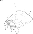
- Figs. 3 and 4 are perspective views of an organ container 2 according to a second embodiment. Like the organ container 1 of the first embodiment, this organ container 2 is also used to temporarily accommodate a liver 9 removed from a donor in a liver transplantation operation.
- Fig. 3 illustrates that an opening 31, through which the liver 9 is put in and out, is closed.
- Fig. 4 illustrates the opening 31 being open.
- the organ container 2 includes a film bag 30, and a chuck 40 provided at the opening 31 of the film bag 30.
- the film bag 30 is a pouch-like container formed of a film.
- the film forming the film bag 30 is made of a flexibly deformable material.
- the film bag 30 has, for example, a rectangular shape.
- the film bag 30 is slightly larger than the liver 9.
- the film bag 30 may have a bottom or side gusset.
- the liver 9 is accommodated inside the film bag 30.
- the film forming the film bag 30 comes in contact with the surface of the liver 9 and becomes deformed along the surface shape of the liver 9.
- the material for the film forming the film bag 30 is a resin having bioadaptability and sterilization retention properties and also having flexibility.
- polypropylene, polyethylene, polyurethane, polyvinylidene chloride, polystyrene, an elastomeric resin, silicon, rubber, a gel material, or polyamide may be used as the material for the film bag 30.
- the film bag 30 may be permeable to a preservation solution, or may be impermeable to the preservation solution. Whether the film bag 30 has fluid permeability may be appropriately selected according to the circumstances where the film bag 30 is used.
- the film bag 30 may also have the property of being permeable to gases such as oxygen.
- the chuck 40 serves as an opening and closing part provided at the end of the film bag 30.
- the chuck 40 includes a pair of chuck members 41.
- the pair of chuck members 41 has minute projections and depressions 42 to be fitted in one another.
- the projections and depressions 42 of one of the chuck members 41 are fitted in the projections and depressions 42 of the other chuck member 41 so that the chuck members 41 come in intimate contact with each other. Accordingly, the film bag 30 is sealed.
- the fitting of the projections and depressions 42 is released and the opening 31 of the film bag 30 becomes opened.
- the material for the chuck members 41 is, for example, a resin that is the same as the material for the film bag 30.
- each of the pair of chuck members 41 has two grooves 43.
- the two grooves 43 of one chuck member 41 are provided at positions opposite to the two grooves of the other chuck member 41.
- the supplying tube 91 and the drain tube 92 connected to the liver 9 are respectively fitted in the two grooves 43 of each chuck member 41. That is, the supplying tube 91 and the drain tube 92 extend from the liver 9 held inside the film bag 30 to the outside of the film bag 30 through the grooves 43. This structure reduces shifts in the positions of the supplying tube 91 and the drain tube 92.
- these two grooves 43 serve as a tube holder that holds the supplying tube 91 and the drain tube 92.
- the two grooves 43 may be provided in only one of the pair of chuck members 41.
- the pair of chuck members 41 is first separated from each other to open the end of the film bag 30. Then, the liver 9 removed from the donor is inserted into the film bag 30 through the space between the pair of chuck members 41. At this time, the liver 9 is connected to the supplying tube 91 and the drain tube 92. When the liver 9 is accommodated in the film bag 30, the supplying tube 91 and the drain tube 92 are fitted in the grooves 43 of the chuck members 41. Then, the pair of chuck members 41 is brought into intimate contact with each other. In this way, the film bag 30 is closed.
- the pair of chuck members 41 is first separated from each other to open the end of the film bag 30. Then, the supplying tube 91 and the drain tube 92 are removed from the grooves 43 of the chuck members 41. Thereafter, the liver 9 is taken out of the film bag 30 and transplanted into the recipient.
- this organ container 2 is capable of holding not only the liver 9 but also the supplying tube 91 and the drain tube 92.
- the organ container 2 can preserve the liver 9 while allowing the preservation solution to be perfused through the liver 9 via the supplying tube 91 and the drain tube 92.
- this organ container 1 accommodates the liver 9 inside the film bag 30 having flexibility. Then, the organ container 2 brings the inner face of the film bag 30 into contact with the surface of the liver 9 to hold the liver 9. Accordingly, the organ container 2 can preserve the liver 9 while reducing the movement of the liver 9 relative to the film bag 30.
- the organ container 2 can also reduce damage to the surface of the liver 9 more than in the case where the liver 9 is held by a rigid body.
- the present embodiment uses the integrated film bag 30, instead of a plurality of films, to accommodate the liver 9. This reduces the number of components of the organ container 2. Besides, in the present embodiment, the film bag 30 and the chuck 40 are integrated with each other. This further reduces the number of components of the organ container 2. As a result, the organ container 2 can be handled with more ease.
- the chuck 40 may be omitted, and the opening 31 of the film bag 30 may be sealed with a clip serving as an opening and closing part.
- the clip may be provided with grooves serving as a tube holder.
- the chuck 40 may be omitted, and a drawstring 50 serving as an opening and closing part may be provided in the opening of the film bag 30 as illustrated in Fig. 5 .
- the opening 31 of the film bag 30 can be tightened or loosened by pulling a drawstring 50, as in the case of a drawstring bag.
- the tightened opening 31 serves as a tube holder that holds the supplying tube 91 and the drain tube 92.
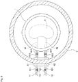
- the organ container 1 according to the first embodiment may be accommodated inside an outer casing 3 having air-tightness or liquid-tightness.
- the outer casing 3 is preferably a rigid body that does not become easily deformed. With this structure, it is possible to easily transport the liver 9 while suppressing the application of pressure to the films.
- the inside of the outer casing 3 may be filled with a preservation solution, together with the organ container 1.
- the outer casing 3 may also have a warm retaining function and a thermal insulating function in order to maintain the internal temperature constant.
- the outer casing 3 is fixed to a pair of relay tubes 61 and 62.
- One ends of the relay tubes 61 and 62 are located outside the outer casing 3.
- the one ends of the relay tubes 61 and 62 are provided respectively with connectors 611 and 621, each having a push button for release.
- This structure enables the user to disconnect and connect the connectors 611 and 621 of the relay tubes 61 and 62 by one touch respectively from and to external tubes 71 and 72 that respectively have corresponding connectors 711 and 712.
- the other ends of the relay tubes 61 and 62 are located inside the outer casing 3.
- the other ends of the relay tubes 61 and 62 are provided respectively with connectors 612 and 622, each having a push button for release.
- the external ends of the supplying tube 91 and the drain tube 92 are provided respectively with connectors 911 and 921 that correspond respectively to the connectors 612 and 622. This enables the user to disconnect and connect the connector 612 of the relay tube 61 by one touch from and to the connector 911 of the supplying tube 91.
- the user is also able to disconnect and connect the connector 622 of the other relay tube 62 by one touch from and to the connector 921 of the drain tube 92.
- the above-described connector structure By employing the above-described connector structure, it is possible to connect and disconnect the tubes while maintaining the insides of the tubes clean. In organ transplantation operations, quick treatment is extremely important. Combined use of the above-described connector structure and the organ container 1 enables more reliably and more quickly advancing organ transplantation operations. Note that the above-described connector structure may be provided only either outside or inside the outer casing 3.
- organ container 2 of the second embodiment may also be accommodated in the outer casing 3.
- first and second embodiments describe the organ containers that accommodate the liver 9.
- these organ containers may be configured to accommodate organs other than the liver 9, such as a heart, a pancreas, or a kidney.
- the liver 9 is connected to the two tubes 91 and 92.
- the number of tubes connected to an organ may be one, or may be three or more.
Landscapes
- Health & Medical Sciences (AREA)
- Life Sciences & Earth Sciences (AREA)
- Engineering & Computer Science (AREA)
- Wood Science & Technology (AREA)
- Zoology (AREA)
- Bioinformatics & Cheminformatics (AREA)
- Organic Chemistry (AREA)
- Chemical & Material Sciences (AREA)
- General Health & Medical Sciences (AREA)
- Biomedical Technology (AREA)
- Genetics & Genomics (AREA)
- Biotechnology (AREA)
- Microbiology (AREA)
- Sustainable Development (AREA)
- Biochemistry (AREA)
- General Engineering & Computer Science (AREA)
- Clinical Laboratory Science (AREA)
- Environmental Sciences (AREA)
- Dentistry (AREA)
- Molecular Biology (AREA)
- Agricultural Chemicals And Associated Chemicals (AREA)
Abstract
Description
- The present invention relates to an organ container that accommodates an organ.
- In organ transplant operations such as liver transplantation, an organ is temporarily preserved outside the body during the period from when the organ is removed from the donor to when the organ is transplanted into the recipient. At this time, the organ is connected to tubes so that a preservation solution is perfused through the organ in order to prevent the organ from becoming ischemic. In the case where the removal of the organ from the donor and the transplantation of the organ into the recipient are conducted at different places, the organ also needs to be transported while being preserved.
- For example,
Patent Document 1 describes a conventional device for preserving an organ outside the body. - Patent Document 1: Japanese Patent Application Laid-Open No.
H3-151303 - The device described in
Patent Document 1 uses a hammock made of hydrophobic cloth to hold an organ. However, merely placing the organ on the hammock as inPatent Document 1 increases the likelihood of the position of the organ being shifted relative to the hammock. It is thus difficult to transport the organ from the donor to the recipient without damage. - The present invention has been made in view of such circumstances, and it is an object of the present invention to provide an organ container that is capable of preserving an organ while allowing a liquid to be perfused through the organ and that is also capable of reducing the occurrence of a shift in the position of the organ and damage to the organ.
- In order to solve the above-described problem, a first aspect of the present invention is an organ container for containing an organ, and includes a flexible film that holds the organ, an opening and closing part that opens and closes an edge of the film, and a tube holder that holds a tube extending between the organ in the film and an outside of the film.
- A second aspect of the present invention is the organ container according to the first aspect, wherein the film incudes a sheet-like first film that covers a lower part of the organ, and a sheet-like second film that covers an upper part of the organ, and the organ is sandwiched and held between the first film and the second film.
- A third aspect of the present invention is the organ container according to the second aspect, wherein the opening and closing part includes a ring-shaped lower frame that supports peripheral portions of the first film and the second film from an underside, the peripheral portions overlapping each other, and a ring-shaped upper frame that sandwiches the peripheral portions of the first film and the second film with the lower frame.
- A fourth aspect of the present invention is the organ container according to the third aspect. This organ container further includes a locking part that locks and fixes the lower frame and the upper frame to each other by bringing the lower frame and the upper frame close to each other.
- A fifth aspect of the present invention is the organ container according to the third or fourth aspect, wherein the tube holder has a groove provided in at least one of an upper face of the lower frame and a lower face of the upper frame, and the tube is fitted in the groove.
- A sixth aspect of the present invention is the organ container according to the fifth aspect, wherein the tube holder has a plurality of grooves, each of which is the groove, and the plurality of grooves are provided at intervals in a circumferential direction.
- A seventh aspect of the present invention is the organ container according to the first aspect. This organ container includes a pouch-like film bag formed of the film. The organ is accommodated in the film bag.
- An eighth aspect of the present invention is the organ container according to the seventh aspect, wherein the opening and closing part is an openable and closable chuck provided at an opening of the film bag.
- A ninth aspect of the present invention is the organ container according to the eighth aspect, wherein the chuck includes a pair of chuck members capable of becoming in intimate contact with and separated from each other, the tube holder has a groove provided in at least one of the pair of chuck members, and the tube is fitted in the groove.
- A tenth aspect of the present invention is the organ container according to the seventh aspect, wherein the opening and closing part includes a drawstring capable of tightening and loosening the opening of the film bag.
- An eleventh aspect of the present invention is the organ container according to any one of the first to tenth aspects, wherein the film is made of a resin.
- According to the first to eleventh aspects of the present invention, it is possible to hold the organ while allowing a liquid to be perfused through the organ via the tube. It is also possible to reduce the movement of the organ relative to the organ container and to reduce damage to the organ.
- In particular, according to the second aspect, using the separate first and second films allows these films to become wide open vertically. This facilitates putting the organ into and out of the organ container.
- In particular, according to the fourth aspect, the lower frame and the upper frame can be fixed to each other by one touch without use of a fastening device such as a screw.
- In particular, according to the fifth aspect, it is possible to hold the tube while reducing a shift in the position of the tube.
- In particular, according to the sixth aspect, the tube can be fixed in any of the grooves prepared in advance.
- In particular, according to the seventh aspect, the number of components of the organ container can be reduced.
- In particular, according to the ninth aspect, it is possible to hold the tube while reducing a shift in the position of the tube.
-
-
Fig. 1 is a perspective view of an organ container according to a first embodiment; -
Fig. 2 is an exploded perspective view of the organ container according to the first embodiment; -
Fig. 3 is a perspective view of an organ container according to a second embodiment; -
Fig. 4 is a perspective view of the organ container according to the second embodiment; -
Fig. 5 is a perspective view of an organ container according to a variation; and -
Fig. 6 is a perspective view of an organ container according to another variation. - Hereinafter, embodiments of the present invention will be described with reference to the drawings.
- In the present application, donors and recipients may be humans, or may be non-human animals. That is, in the present application, organs including livers may be human organs, or may be organs of non-human animals. The non-human animals may be rodents such as mice and rats; ungulates such as pigs, goats, and sheep; non-human primates such as chimpanzees; or other non-human mammals, or may be nonmammalian animals.
-
Fig. 1 is a perspective view of anorgan container 1 according to a first embodiment.Fig. 2 is an exploded perspective view of theorgan container 1. - This
organ container 1 is a container that temporarily accommodates aliver 9 removed from the donor in a liver transplantation operation. Theliver 9 after being removed from the donor needs to be preserved while a preservation solution is being perfused therethrough, during the period until when the liver is transplanted into the recipient. For this reason, theliver 9 is connected to a supplyingtube 91 for supplying the preservation solution and adrain tube 92 for draining the preservation solution. The supplyingtube 91 is connected to, for example, the portal vein or hepatic artery of theliver 9 through a catheter. Thedrain tube 92 is connected to, for example, the suprahepatic inferior vena cava or infrahepatic inferior vena cava of theliver 9 through a catheter. - As illustrated in
Figs. 1 and2 , theorgan container 1 according to the present embodiment includes afirst film 11, asecond film 12, alower frame 21, and anupper frame 22. - The
first film 11 is a sheet film that covers the lower part of theliver 9. Thesecond film 12 is a sheet film that covers the upper part of theliver 9. Thefirst film 11 and thesecond film 12 are both made of a flexibly deformable material. Thefirst film 11 and thesecond film 12 according to the present embodiment have a circular shape when viewed from above. Alternatively, thefirst film 11 and thesecond film 12 may have other shapes such as an oval shape. Thefirst film 11 and thesecond film 12 have approximately the same size and are larger than theliver 9 when viewed from above. The upper face of thefirst film 11 comes in contact with the lower part of theliver 9. The lower face of thesecond film 12 comes in contact with the upper part of theliver 9. That is, theliver 9 is sandwiched and held between thefirst film 11 and thesecond film 12. Thefirst film 11 and thesecond film 12 have flexibility, and therefore each become deformed depending on the surface shape of theliver 9. - The material for the
first film 11 and thesecond film 12 is a resin having bioadaptability and sterilization retention properties and also having flexibility. For example, polypropylene, polyethylene, polyurethane, polyvinylidene chloride, polystyrene, an elastomeric resin, silicon, rubber, a gel material, or polyamide may be used as the material for thefirst film 11 and thesecond film 12. Thefirst film 11 and thesecond film 12 may be permeable to the preservation solution, or may be impermeable to the preservation solution. Whether thefirst film 11 and thesecond film 12 have fluid permeability may be appropriately selected according to the circumstances where these films are used. Thefirst film 11 and thesecond film 12 may also have the property of being permeable to gases such as oxygen. - The
lower frame 21 is a ring-shaped member arranged below thefirst film 11. The upper face of thelower frame 21 comes in contact with the lower face of a peripheral portion of thefirst film 11 and supports the peripheral portion of thefirst film 11 from the underside. Theupper frame 22 is a ring-shaped member arranged above thesecond film 12. The lower face of theupper frame 22 comes in contact with the upper face of a peripheral portion of thesecond film 12. Thelower frame 21 and theupper frame 22 are rigid bodies that do not easily become deformed. That is, thelower frame 21 and theupper frame 22 are made of a material having less flexibility than thefirst film 11 and thesecond film 12. The material for thelower frame 21 and theupper frame 22 is for example, a resin or a metal. - In the present embodiment, the
lower frame 21 and theupper frame 22 serve as an opening and closing part that opens and closes the edges of thefirst film 11 and thesecond film 12. In the example illustrated inFigs. 1 and2 , thelower frame 21 and theupper frame 22 have a circular shape when viewed from above. Alternatively, thelower frame 21 and theupper frame 22 may have other shapes such as a rectangular shape. - In use of the
organ container 1, thefirst film 11 is first arranged on the upper side of thelower frame 21. Then, theliver 9 removed from the donor is placed on the center of the upper face of thefirst film 11. Next, the upper part of theliver 9 is covered with thesecond film 12. At this time, the peripheral portion of thefirst film 11 and the peripheral portion of thesecond film 12 are brought to overlap one on the other. That is, the upper face of the peripheral portion of thefirst film 11 and the lower face of the peripheral portion of thesecond film 12 are brought into contact with each other. Alternatively, thelower frame 21 and thefirst film 11 may be fixed beforehand to each other with a fastening device such as a clip. - The
upper frame 22 includes a plurality of lockingparts 23. Each lockingpart 23 has, for example, anarm 231 that extends downward from the edge of theupper frame 22, and aclaw 232 provided at the tip of thearm 231. When theupper frame 22 is brought closer to thelower frame 21 from above, the lockingparts 23 are locked to thelower frame 21. Accordingly, thelower frame 21 and theupper frame 22 are fixed to each other as illustrated inFig. 1 . - The aforementioned peripheral portions of the
first film 11 and thesecond film 12 are sandwiched between the upper face of thelower frame 21 and the lower face of theupper frame 22. Accordingly, the peripheral portions of thefirst film 11 and thesecond film 12 are closed. As a result, theliver 9 is held between thefirst film 11 and thesecond film 12. - The
lower frame 21 has a plurality ofgrooves 24. Thegrooves 24 are provided at intervals (e.g., equal intervals) in the circumferential direction in the upper face of thelower frame 21. Eachgroove 24 extends radially from the inner peripheral edge of the upper face of thelower frame 21 to the outer peripheral edge thereof. Each of the supplyingtube 91 and thedrain tube 92 connected to theliver 9 is fitted in one of thegrooves 24 via thefirst film 11. The supplyingtube 91 and thedrain tube 92 extend from theliver 9 held inside thefirst film 11 and thesecond film 12 to the outside of thefirst film 11 and thesecond film 12 through thegrooves 24. This structure reduces shifts in the positions of the supplyingtube 91 and thedrain tube 92. - In the present embodiment, these
grooves 24 serve as a tube holder that holds the supplyingtube 91 and thedrain tube 92. Alternatively, thegrooves 24 may be provided in the lower face of theupper frame 22. As another alternative, thegrooves 24 may be provided in both the upper face of thelower frame 21 and the lower face of theupper frame 22. - In the case of transplanting the
liver 9 held by theorgan container 1 into the recipient, the lockingparts 23 are first detached from thelower frame 21. Then, thelower frame 21 and theupper frame 22 are vertically separated from each other. Next, the peripheral portions of thefirst film 11 and thesecond film 12 are opened, and thesecond film 12 is stripped off. Thereafter, theliver 9 is taken out of the upper face of thefirst film 11 and transplanted into the recipient. - As described above, this
organ container 1 is capable of holding not only theliver 9 but also the supplyingtube 91 and thedrain tube 92. Thus, theorgan container 1 can preserve theliver 9 while allowing the preservation solution to be perfused through theliver 9 via the supplyingtube 91 and thedrain tube 92. Moreover, thisorgan container 1 accommodates theliver 9 between thefirst film 11 and thesecond film 12, both having flexibility. Theorgan container 1 holds theliver 9 by bringing thefirst film 11 and thesecond film 12 into contact with the surface of theliver 9. Accordingly, theorgan container 1 can preserve theliver 9 while reducing the movement of theliver 9 relative to thefirst film 11 and thesecond film 12. Theorgan container 1 can also reduce damage to the surface of theliver 9 more than in the case where theliver 9 is held by a rigid body. - In particular, the present embodiment uses the two
separate films liver 9. This allows thefirst film 11 and thesecond film 12 to become wide open vertically as illustrated inFig. 2 . Thus, theliver 9 can be put in and out of theorgan container 1 with ease. - The
lower frame 21 and theupper frame 22 according to the present embodiment can be fixed to each other by one touch with the lockingparts 23 by simply bringing them close to each other. This eliminates the need to use a fastening device such as a screw to fix thelower frame 21 and theupper frame 22. Accordingly, theliver 9 removed from the donor can be speedily accommodated in theorgan container 1. Alternatively, the lockingparts 23 may be provided in thelower frame 21. As another alternative, the lockingparts 23 may be omitted, and thelower frame 21 and theupper frame 22 may be fixed to each other with a fastening device such as a screw or a clip. -
Figs. 3 and4 are perspective views of anorgan container 2 according to a second embodiment. Like theorgan container 1 of the first embodiment, thisorgan container 2 is also used to temporarily accommodate aliver 9 removed from a donor in a liver transplantation operation.Fig. 3 illustrates that anopening 31, through which theliver 9 is put in and out, is closed.Fig. 4 illustrates theopening 31 being open. - As illustrated in
Figs. 3 and4 , theorgan container 2 includes afilm bag 30, and achuck 40 provided at theopening 31 of thefilm bag 30. - The
film bag 30 is a pouch-like container formed of a film. The film forming thefilm bag 30 is made of a flexibly deformable material. Thefilm bag 30 has, for example, a rectangular shape. Thefilm bag 30 is slightly larger than theliver 9. Thefilm bag 30 may have a bottom or side gusset. Theliver 9 is accommodated inside thefilm bag 30. The film forming thefilm bag 30 comes in contact with the surface of theliver 9 and becomes deformed along the surface shape of theliver 9. - The material for the film forming the
film bag 30 is a resin having bioadaptability and sterilization retention properties and also having flexibility. For example, polypropylene, polyethylene, polyurethane, polyvinylidene chloride, polystyrene, an elastomeric resin, silicon, rubber, a gel material, or polyamide may be used as the material for thefilm bag 30. Thefilm bag 30 may be permeable to a preservation solution, or may be impermeable to the preservation solution. Whether thefilm bag 30 has fluid permeability may be appropriately selected according to the circumstances where thefilm bag 30 is used. Thefilm bag 30 may also have the property of being permeable to gases such as oxygen. - The
chuck 40 serves as an opening and closing part provided at the end of thefilm bag 30. Thechuck 40 includes a pair ofchuck members 41. The pair ofchuck members 41 has minute projections anddepressions 42 to be fitted in one another. When the pair ofchuck members 41 is brought into contact with each other to apply pressure, the projections anddepressions 42 of one of thechuck members 41 are fitted in the projections anddepressions 42 of theother chuck member 41 so that thechuck members 41 come in intimate contact with each other. Accordingly, thefilm bag 30 is sealed. When the pair ofchuck members 41 is separated from each other, the fitting of the projections anddepressions 42 is released and theopening 31 of thefilm bag 30 becomes opened. The material for thechuck members 41 is, for example, a resin that is the same as the material for thefilm bag 30. - As illustrated in
Fig. 4 , each of the pair ofchuck members 41 has twogrooves 43. The twogrooves 43 of onechuck member 41 are provided at positions opposite to the two grooves of theother chuck member 41. The supplyingtube 91 and thedrain tube 92 connected to theliver 9 are respectively fitted in the twogrooves 43 of eachchuck member 41. That is, the supplyingtube 91 and thedrain tube 92 extend from theliver 9 held inside thefilm bag 30 to the outside of thefilm bag 30 through thegrooves 43. This structure reduces shifts in the positions of the supplyingtube 91 and thedrain tube 92. - In the present embodiment, these two
grooves 43 serve as a tube holder that holds the supplyingtube 91 and thedrain tube 92. Alternatively, the twogrooves 43 may be provided in only one of the pair ofchuck members 41. - In use of the
organ container 2, the pair ofchuck members 41 is first separated from each other to open the end of thefilm bag 30. Then, theliver 9 removed from the donor is inserted into thefilm bag 30 through the space between the pair ofchuck members 41. At this time, theliver 9 is connected to the supplyingtube 91 and thedrain tube 92. When theliver 9 is accommodated in thefilm bag 30, the supplyingtube 91 and thedrain tube 92 are fitted in thegrooves 43 of thechuck members 41. Then, the pair ofchuck members 41 is brought into intimate contact with each other. In this way, thefilm bag 30 is closed. - In the case of transplanting the
liver 9 held in thefilm bag 30 into the recipient, the pair ofchuck members 41 is first separated from each other to open the end of thefilm bag 30. Then, the supplyingtube 91 and thedrain tube 92 are removed from thegrooves 43 of thechuck members 41. Thereafter, theliver 9 is taken out of thefilm bag 30 and transplanted into the recipient. - As described above, this
organ container 2 is capable of holding not only theliver 9 but also the supplyingtube 91 and thedrain tube 92. Thus, theorgan container 2 can preserve theliver 9 while allowing the preservation solution to be perfused through theliver 9 via the supplyingtube 91 and thedrain tube 92. Moreover, thisorgan container 1 accommodates theliver 9 inside thefilm bag 30 having flexibility. Then, theorgan container 2 brings the inner face of thefilm bag 30 into contact with the surface of theliver 9 to hold theliver 9. Accordingly, theorgan container 2 can preserve theliver 9 while reducing the movement of theliver 9 relative to thefilm bag 30. Theorgan container 2 can also reduce damage to the surface of theliver 9 more than in the case where theliver 9 is held by a rigid body. - In particular, the present embodiment uses the
integrated film bag 30, instead of a plurality of films, to accommodate theliver 9. This reduces the number of components of theorgan container 2. Besides, in the present embodiment, thefilm bag 30 and thechuck 40 are integrated with each other. This further reduces the number of components of theorgan container 2. As a result, theorgan container 2 can be handled with more ease. - Alternatively, the
chuck 40 may be omitted, and theopening 31 of thefilm bag 30 may be sealed with a clip serving as an opening and closing part. In this case, the clip may be provided with grooves serving as a tube holder. - As another alternative, the
chuck 40 may be omitted, and adrawstring 50 serving as an opening and closing part may be provided in the opening of thefilm bag 30 as illustrated inFig. 5 . In the example inFig. 5 , theopening 31 of thefilm bag 30 can be tightened or loosened by pulling adrawstring 50, as in the case of a drawstring bag. In this case, the tightenedopening 31 serves as a tube holder that holds the supplyingtube 91 and thedrain tube 92. - While the first and second embodiments of the present invention have been described thus far, the present invention is not limited to the embodiments described above.
- As illsutrated in
Fig. 6 , theorgan container 1 according to the first embodiment may be accommodated inside anouter casing 3 having air-tightness or liquid-tightness. Theouter casing 3 is preferably a rigid body that does not become easily deformed. With this structure, it is possible to easily transport theliver 9 while suppressing the application of pressure to the films. The inside of theouter casing 3 may be filled with a preservation solution, together with theorgan container 1. Theouter casing 3 may also have a warm retaining function and a thermal insulating function in order to maintain the internal temperature constant. - In the example in
Fig. 6 , theouter casing 3 is fixed to a pair ofrelay tubes relay tubes outer casing 3. The one ends of therelay tubes connectors connectors relay tubes external tubes - The other ends of the
relay tubes outer casing 3. The other ends of therelay tubes connectors tube 91 and thedrain tube 92 are provided respectively withconnectors connectors connector 612 of therelay tube 61 by one touch from and to theconnector 911 of the supplyingtube 91. The user is also able to disconnect and connect theconnector 622 of theother relay tube 62 by one touch from and to theconnector 921 of thedrain tube 92. - By employing the above-described connector structure, it is possible to connect and disconnect the tubes while maintaining the insides of the tubes clean. In organ transplantation operations, quick treatment is extremely important. Combined use of the above-described connector structure and the
organ container 1 enables more reliably and more quickly advancing organ transplantation operations. Note that the above-described connector structure may be provided only either outside or inside theouter casing 3. - Similarly, the
organ container 2 of the second embodiment may also be accommodated in theouter casing 3. - The above first and second embodiments describe the organ containers that accommodate the
liver 9. However, these organ containers may be configured to accommodate organs other than theliver 9, such as a heart, a pancreas, or a kidney. In the above-described first and second embodiments, theliver 9 is connected to the twotubes - Components described in the above embodiments and variations may be appropriately combined appropriately within a range that causes no contradictions.
-
- 1, 2
- Organ container
- 3
- Outer casing
- 9
- Liver
- 11
- First film
- 12
- Second film
- 21
- Lower frame
- 22
- Upper frame
- 23
- Locking part
- 24
- Groove
- 30
- Film bag
- 31
- Opening
- 40
- Chuck
- 41
- Chuck member
- 42
- Projection and depression
- 43
- Groove
- 50
- Drawstring
- 61, 62
- Relay tube
- 91
- Supplying tube
- 92
- Drain tube
Claims (11)
- An organ container that accommodates an organ, comprising:a flexible film that holds said organ;an opening and closing part that opens and closes an edge of said film; anda tube holder that holds a tube extending between said organ in said film and an outside of said film.
- The organ container according to claim 1, wherein
said film incudes:a sheet-like first film that covers a lower part of said organ; anda sheet-like second film that covers an upper part of said organ, andsaid organ is sandwiched and held between said first film and said second film. - The organ container according to claim 2, wherein
said opening and closing part includes:a ring-shaped lower frame that supports peripheral portions of said first film and said second film from an underside, the peripheral portions overlapping each other; anda ring-shaped upper frame that sandwiches said peripheral portions of said first film and said second film with said lower frame. - The organ container according to claim 3, further comprising:
a locking part that locks and fixes said lower frame and said upper frame to each other by bringing said lower frame and said upper frame close to each other. - The organ container according to claim 3 or 4, wherein
said tube holder has a groove provided in at least one of an upper face of said lower frame and a lower face of said upper frame, and
said tube is fitted in said groove. - The organ container according to claim 5, wherein
said tube holder has a plurality of grooves, each of which is said groove, and
said plurality of grooves are provided at intervals in a circumferential direction. - The organ container according to claim 1, comprising:a pouch-like film bag formed of said film, andsaid organ is accommodated in said film bag.
- The organ container according to claim 7, wherein
said opening and closing part is an openable and closable chuck provided at an opening of said film bag. - The organ container according to claim 8, wherein
said chuck includes a pair of chuck members capable of becoming in intimate contact with and separated from each other,
said tube holder has a groove provided in at least one of said pair of chuck members, and
said tube is fitted in said groove. - The organ container according to claim 7, wherein
said opening and closing part includes a drawstring capable of tightening and loosening the opening of said film bag. - The organ container according to any one of claims 1 to 10, wherein
said film is made of a resin.
Applications Claiming Priority (2)
| Application Number | Priority Date | Filing Date | Title |
|---|---|---|---|
| JP2017227718A JP6967434B2 (en) | 2017-11-28 | 2017-11-28 | Organ container |
| PCT/JP2018/036652 WO2019106936A1 (en) | 2017-11-28 | 2018-10-01 | Organ container |
Publications (2)
| Publication Number | Publication Date |
|---|---|
| EP3718402A1 true EP3718402A1 (en) | 2020-10-07 |
| EP3718402A4 EP3718402A4 (en) | 2021-03-24 |
Family
ID=66664871
Family Applications (1)
| Application Number | Title | Priority Date | Filing Date |
|---|---|---|---|
| EP18884777.6A Withdrawn EP3718402A4 (en) | 2017-11-28 | 2018-10-01 | ORGAN CONTAINER |
Country Status (5)
| Country | Link |
|---|---|
| US (1) | US11459534B2 (en) |
| EP (1) | EP3718402A4 (en) |
| JP (1) | JP6967434B2 (en) |
| CN (1) | CN111315215B (en) |
| WO (1) | WO2019106936A1 (en) |
Cited By (4)
| Publication number | Priority date | Publication date | Assignee | Title |
|---|---|---|---|---|
| EP3756460A1 (en) * | 2019-06-26 | 2020-12-30 | SCREEN Holdings Co., Ltd. | Frame and organ holder |
| EP4018827A1 (en) * | 2020-12-24 | 2022-06-29 | SCREEN Holdings Co., Ltd. | Organ container |
| WO2022204436A1 (en) * | 2021-03-25 | 2022-09-29 | Vanderbilt University | Veno-arterial venous cross-circulation for extracorporeal organ support |
| WO2024133447A1 (en) * | 2022-12-23 | 2024-06-27 | Centre D'etude Des Cellules Souches (Cecs) | Closed device for culturing and transporting cell therapy product |
Families Citing this family (8)
| Publication number | Priority date | Publication date | Assignee | Title |
|---|---|---|---|---|
| JP2021017433A (en) * | 2019-07-24 | 2021-02-15 | 株式会社Screenホールディングス | Organ storage container |
| JP7355567B2 (en) | 2019-09-11 | 2023-10-03 | 株式会社Screenホールディングス | organ storage container |
| GB2591784A (en) * | 2020-02-06 | 2021-08-11 | Univ Strathclyde | Organ transport apparatus |
| JP7406394B2 (en) * | 2020-02-14 | 2023-12-27 | 株式会社Screenホールディングス | organ storage container |
| JP7532835B2 (en) * | 2020-03-23 | 2024-08-14 | 住友ベークライト株式会社 | Multi-tiered storage vessel set and cell culture vessel set |
| JP7538668B2 (en) * | 2020-09-17 | 2024-08-22 | 株式会社Screenホールディングス | Organ container |
| CN113384379B (en) * | 2021-06-17 | 2022-12-02 | 深圳华越再生医学生物科技有限公司 | For wrapping device for transplanting visceral organs |
| KR20240046256A (en) * | 2021-08-25 | 2024-04-08 | 엔테그리스, 아이엔씨. | rigid frame bag |
Family Cites Families (26)
| Publication number | Priority date | Publication date | Assignee | Title |
|---|---|---|---|---|
| JPS4740995Y1 (en) | 1969-07-17 | 1972-12-12 | ||
| CN86203016U (en) * | 1986-05-17 | 1986-12-10 | 上海市塑料研究所 | Medical ultralow temp. cell and tissue-storing bag |
| JPH02111701A (en) * | 1988-10-20 | 1990-04-24 | Olympus Optical Co Ltd | Internal organ storing unit |
| JPH03151303A (en) | 1989-11-06 | 1991-06-27 | Olympus Optical Co Ltd | Organ-preservation apparatus |
| JPH0616501A (en) * | 1992-05-06 | 1994-01-25 | Tonokura Ika Kogyo Kk | Method and device for carrying organ and pump for organ-carrying device |
| JPH07101802A (en) * | 1993-10-01 | 1995-04-18 | Kohei Hasegawa | Accommodation of encleated organ |
| JPH07101801A (en) * | 1993-10-01 | 1995-04-18 | Kohei Hasegawa | Accommodation of enucleated organ |
| US8409846B2 (en) * | 1997-09-23 | 2013-04-02 | The United States Of America As Represented By The Department Of Veteran Affairs | Compositions, methods and devices for maintaining an organ |
| US6100082A (en) * | 1997-09-23 | 2000-08-08 | Hassanein; Waleed H. | Perfusion apparatus and method including chemical compositions for maintaining an organ |
| JP3078536B1 (en) * | 1999-04-27 | 2000-08-21 | 博俊 小杉 | Sandwich type packaging container |
| JP2001039473A (en) * | 1999-07-28 | 2001-02-13 | Shiro Ono | Packaging container |
| JP2003267471A (en) * | 2002-03-15 | 2003-09-25 | Nipro Corp | External bag for protecting cryopreservation containers for living tissues |
| US20060121439A1 (en) * | 2002-09-18 | 2006-06-08 | Jan Baker | Organ preservation and transportation apparatus and method |
| NL1024022C2 (en) * | 2003-07-30 | 2005-02-01 | Technologiestichting Stw | Portable preservation device for a donor organ. |
| CN2896900Y (en) * | 2006-03-27 | 2007-05-09 | 董礼明 | Cold storage bag for transplanted kidney |
| ES2750256T3 (en) * | 2008-05-06 | 2020-03-25 | Xvivo Perfusion Ab | Apparatus to house an organ during its evaluation and conservation |
| CN201345874Y (en) * | 2009-01-08 | 2009-11-18 | 孔佑华 | Medical cell tissue cryopreservation bag |
| CN202232704U (en) * | 2011-09-09 | 2012-05-30 | 明英姿 | Special specimen cold storage bag for transplanted kidney |
| JP2016504022A (en) * | 2012-12-07 | 2016-02-12 | ザ ガバニング カウンシル オブ ザ ユニバーシティ オブ トロント | Heart tissue construct and method for producing the same |
| CA2913058C (en) * | 2013-06-07 | 2019-09-17 | Organ Transport Pty Ltd | Organ perfusion system and device |
| CN103688924B (en) * | 2013-12-24 | 2015-07-22 | 大连医科大学 | Transplant cold protection bag |
| US9781920B2 (en) * | 2014-04-09 | 2017-10-10 | Paul Jeffrey Campsen | Suspendable organ transplant system and method of use |
| JP6594097B2 (en) * | 2015-08-17 | 2019-10-23 | トッパン・フォームズ株式会社 | Goods holding container |
| CN205962505U (en) * | 2016-05-19 | 2017-02-22 | 眀英姿 | Multi -functional organ preservation bag |
| US11632951B2 (en) * | 2020-01-31 | 2023-04-25 | Paragonix Technologies, Inc. | Apparatus for tissue transport and preservation |
| JP7527146B2 (en) * | 2020-07-21 | 2024-08-02 | 株式会社Screenホールディングス | Organ Preservation Device |
-
2017
- 2017-11-28 JP JP2017227718A patent/JP6967434B2/en not_active Expired - Fee Related
-
2018
- 2018-10-01 CN CN201880072728.1A patent/CN111315215B/en not_active Expired - Fee Related
- 2018-10-01 US US16/765,283 patent/US11459534B2/en active Active
- 2018-10-01 EP EP18884777.6A patent/EP3718402A4/en not_active Withdrawn
- 2018-10-01 WO PCT/JP2018/036652 patent/WO2019106936A1/en not_active Ceased
Cited By (5)
| Publication number | Priority date | Publication date | Assignee | Title |
|---|---|---|---|---|
| EP3756460A1 (en) * | 2019-06-26 | 2020-12-30 | SCREEN Holdings Co., Ltd. | Frame and organ holder |
| EP4018827A1 (en) * | 2020-12-24 | 2022-06-29 | SCREEN Holdings Co., Ltd. | Organ container |
| WO2022204436A1 (en) * | 2021-03-25 | 2022-09-29 | Vanderbilt University | Veno-arterial venous cross-circulation for extracorporeal organ support |
| WO2024133447A1 (en) * | 2022-12-23 | 2024-06-27 | Centre D'etude Des Cellules Souches (Cecs) | Closed device for culturing and transporting cell therapy product |
| FR3144160A1 (en) * | 2022-12-23 | 2024-06-28 | Centre D'etude Des Cellules Souches (Cecs) | Closed device for culturing and transporting cell therapy products |
Also Published As
| Publication number | Publication date |
|---|---|
| EP3718402A4 (en) | 2021-03-24 |
| US11459534B2 (en) | 2022-10-04 |
| US20200308520A1 (en) | 2020-10-01 |
| JP6967434B2 (en) | 2021-11-17 |
| CN111315215B (en) | 2022-03-15 |
| WO2019106936A1 (en) | 2019-06-06 |
| CN111315215A (en) | 2020-06-19 |
| JP2019094315A (en) | 2019-06-20 |
Similar Documents
| Publication | Publication Date | Title |
|---|---|---|
| US11459534B2 (en) | Organ container | |
| US5348185A (en) | Cassette for sterilizing articles and latch therefor | |
| US20100196873A1 (en) | Systems and Methods for Cryopreservation of Cells | |
| US5031762A (en) | Three envelope package for sterile specimens | |
| JP7143167B2 (en) | Organ-receiving bag and transplantation method | |
| US20090148934A1 (en) | Systems and Methods for Cryopreservation of Cells | |
| AU2015301509B2 (en) | Novel cryopreservation bags and method of use thereof for closed system, high capacity cell-banking | |
| US11992006B2 (en) | Organ preservation system | |
| US20180007890A1 (en) | Freezing bag container | |
| JP6445367B2 (en) | Biological sample transport container and transport method | |
| WO2016016886A1 (en) | Devices and methods for cryopreserving a biological sample by liquid nitrogen | |
| US12507692B2 (en) | Organ container | |
| EP3864960B1 (en) | Organ container | |
| WO2023047976A1 (en) | Organ placement platform, organ storage container, and organ placement method | |
| US20060024818A1 (en) | Safety pouch for cryo-preservation of staminal cells or similar blood components | |
| EP4399973A1 (en) | Organ storage container, organ storage device, and production method for organ storage container | |
| CN110382014A (en) | Device and method for biological processing cell sample | |
| EP4309497A1 (en) | Organ storage container | |
| US10343841B1 (en) | Waste containment and isolating system and method of isolating waste thereof | |
| JP2000185716A (en) | Auxiliary seal for packaging for cryopreservation containers | |
| CN219216076U (en) | Packaging structure and packaging system of artificial valve | |
| FR3027591A1 (en) | PACKAGING FOR TRANSPORTING A PORTION OF THE HUMAN OR ANIMAL BODY |
Legal Events
| Date | Code | Title | Description |
|---|---|---|---|
| STAA | Information on the status of an ep patent application or granted ep patent |
Free format text: STATUS: THE INTERNATIONAL PUBLICATION HAS BEEN MADE |
|
| PUAI | Public reference made under article 153(3) epc to a published international application that has entered the european phase |
Free format text: ORIGINAL CODE: 0009012 |
|
| STAA | Information on the status of an ep patent application or granted ep patent |
Free format text: STATUS: REQUEST FOR EXAMINATION WAS MADE |
|
| 17P | Request for examination filed |
Effective date: 20200618 |
|
| AK | Designated contracting states |
Kind code of ref document: A1 Designated state(s): AL AT BE BG CH CY CZ DE DK EE ES FI FR GB GR HR HU IE IS IT LI LT LU LV MC MK MT NL NO PL PT RO RS SE SI SK SM TR |
|
| AX | Request for extension of the european patent |
Extension state: BA ME |
|
| DAV | Request for validation of the european patent (deleted) | ||
| DAX | Request for extension of the european patent (deleted) | ||
| A4 | Supplementary search report drawn up and despatched |
Effective date: 20210217 |
|
| RIC1 | Information provided on ipc code assigned before grant |
Ipc: A01N 1/02 20060101AFI20210212BHEP |
|
| GRAP | Despatch of communication of intention to grant a patent |
Free format text: ORIGINAL CODE: EPIDOSNIGR1 |
|
| STAA | Information on the status of an ep patent application or granted ep patent |
Free format text: STATUS: GRANT OF PATENT IS INTENDED |
|
| INTG | Intention to grant announced |
Effective date: 20240816 |
|
| RIN1 | Information on inventor provided before grant (corrected) |
Inventor name: YOSHIMOTO, SYUHEI Inventor name: TORAI, SHINJI |
|
| STAA | Information on the status of an ep patent application or granted ep patent |
Free format text: STATUS: THE APPLICATION IS DEEMED TO BE WITHDRAWN |
|
| 18D | Application deemed to be withdrawn |
Effective date: 20241217 |