EP3718277B1 - Configuration d'ensemble de ressources multiples - Google Patents
Configuration d'ensemble de ressources multiples Download PDFInfo
- Publication number
- EP3718277B1 EP3718277B1 EP18885826.0A EP18885826A EP3718277B1 EP 3718277 B1 EP3718277 B1 EP 3718277B1 EP 18885826 A EP18885826 A EP 18885826A EP 3718277 B1 EP3718277 B1 EP 3718277B1
- Authority
- EP
- European Patent Office
- Prior art keywords
- resources
- configuration
- resource
- different
- channel
- Prior art date
- Legal status (The legal status is an assumption and is not a legal conclusion. Google has not performed a legal analysis and makes no representation as to the accuracy of the status listed.)
- Active
Links
- 238000000034 method Methods 0.000 claims description 102
- 238000004891 communication Methods 0.000 claims description 79
- 230000015654 memory Effects 0.000 claims description 21
- 230000008569 process Effects 0.000 description 89
- 230000005540 biological transmission Effects 0.000 description 41
- 238000013507 mapping Methods 0.000 description 40
- 238000013468 resource allocation Methods 0.000 description 29
- 238000012545 processing Methods 0.000 description 28
- 238000005516 engineering process Methods 0.000 description 23
- 238000013459 approach Methods 0.000 description 18
- 238000010586 diagram Methods 0.000 description 18
- 230000011664 signaling Effects 0.000 description 16
- 230000001413 cellular effect Effects 0.000 description 15
- 101000744882 Homo sapiens Zinc finger protein 185 Proteins 0.000 description 11
- 102100040032 Zinc finger protein 185 Human genes 0.000 description 11
- 230000006870 function Effects 0.000 description 6
- 239000004065 semiconductor Substances 0.000 description 4
- 238000013461 design Methods 0.000 description 3
- VJYFKVYYMZPMAB-UHFFFAOYSA-N ethoprophos Chemical compound CCCSP(=O)(OCC)SCCC VJYFKVYYMZPMAB-UHFFFAOYSA-N 0.000 description 3
- 230000007774 longterm Effects 0.000 description 3
- 230000000977 initiatory effect Effects 0.000 description 2
- 238000012986 modification Methods 0.000 description 2
- 230000004048 modification Effects 0.000 description 2
- 230000003287 optical effect Effects 0.000 description 2
- 230000001105 regulatory effect Effects 0.000 description 2
- 238000000926 separation method Methods 0.000 description 2
- 238000012546 transfer Methods 0.000 description 2
- 101150071746 Pbsn gene Proteins 0.000 description 1
- 230000002776 aggregation Effects 0.000 description 1
- 238000004220 aggregation Methods 0.000 description 1
- 230000003321 amplification Effects 0.000 description 1
- 238000003491 array Methods 0.000 description 1
- 239000000969 carrier Substances 0.000 description 1
- 239000003795 chemical substances by application Substances 0.000 description 1
- 230000001276 controlling effect Effects 0.000 description 1
- 239000013078 crystal Substances 0.000 description 1
- 125000004122 cyclic group Chemical group 0.000 description 1
- 230000000694 effects Effects 0.000 description 1
- 238000002955 isolation Methods 0.000 description 1
- 239000004973 liquid crystal related substance Substances 0.000 description 1
- 230000007246 mechanism Effects 0.000 description 1
- 238000010295 mobile communication Methods 0.000 description 1
- 238000012544 monitoring process Methods 0.000 description 1
- 238000003199 nucleic acid amplification method Methods 0.000 description 1
- 230000008520 organization Effects 0.000 description 1
- 230000002093 peripheral effect Effects 0.000 description 1
- 230000001953 sensory effect Effects 0.000 description 1
- 239000007787 solid Substances 0.000 description 1
- 230000003068 static effect Effects 0.000 description 1
- 239000000758 substrate Substances 0.000 description 1
- 230000000007 visual effect Effects 0.000 description 1
Images


Classifications
-
- H—ELECTRICITY
- H04—ELECTRIC COMMUNICATION TECHNIQUE
- H04L—TRANSMISSION OF DIGITAL INFORMATION, e.g. TELEGRAPHIC COMMUNICATION
- H04L27/00—Modulated-carrier systems
- H04L27/26—Systems using multi-frequency codes
- H04L27/2601—Multicarrier modulation systems
- H04L27/2602—Signal structure
-
- H—ELECTRICITY
- H04—ELECTRIC COMMUNICATION TECHNIQUE
- H04L—TRANSMISSION OF DIGITAL INFORMATION, e.g. TELEGRAPHIC COMMUNICATION
- H04L5/00—Arrangements affording multiple use of the transmission path
- H04L5/0001—Arrangements for dividing the transmission path
- H04L5/0003—Two-dimensional division
- H04L5/0005—Time-frequency
- H04L5/0007—Time-frequency the frequencies being orthogonal, e.g. OFDM(A), DMT
- H04L5/001—Time-frequency the frequencies being orthogonal, e.g. OFDM(A), DMT the frequencies being arranged in component carriers
-
- H—ELECTRICITY
- H04—ELECTRIC COMMUNICATION TECHNIQUE
- H04L—TRANSMISSION OF DIGITAL INFORMATION, e.g. TELEGRAPHIC COMMUNICATION
- H04L5/00—Arrangements affording multiple use of the transmission path
- H04L5/0091—Signaling for the administration of the divided path
- H04L5/0094—Indication of how sub-channels of the path are allocated
-
- H—ELECTRICITY
- H04—ELECTRIC COMMUNICATION TECHNIQUE
- H04W—WIRELESS COMMUNICATION NETWORKS
- H04W72/00—Local resource management
- H04W72/20—Control channels or signalling for resource management
- H04W72/23—Control channels or signalling for resource management in the downlink direction of a wireless link, i.e. towards a terminal
-
- H—ELECTRICITY
- H04—ELECTRIC COMMUNICATION TECHNIQUE
- H04L—TRANSMISSION OF DIGITAL INFORMATION, e.g. TELEGRAPHIC COMMUNICATION
- H04L27/00—Modulated-carrier systems
- H04L27/26—Systems using multi-frequency codes
-
- H—ELECTRICITY
- H04—ELECTRIC COMMUNICATION TECHNIQUE
- H04L—TRANSMISSION OF DIGITAL INFORMATION, e.g. TELEGRAPHIC COMMUNICATION
- H04L5/00—Arrangements affording multiple use of the transmission path
- H04L5/003—Arrangements for allocating sub-channels of the transmission path
-
- H—ELECTRICITY
- H04—ELECTRIC COMMUNICATION TECHNIQUE
- H04L—TRANSMISSION OF DIGITAL INFORMATION, e.g. TELEGRAPHIC COMMUNICATION
- H04L5/00—Arrangements affording multiple use of the transmission path
- H04L5/003—Arrangements for allocating sub-channels of the transmission path
- H04L5/0048—Allocation of pilot signals, i.e. of signals known to the receiver
- H04L5/0051—Allocation of pilot signals, i.e. of signals known to the receiver of dedicated pilots, i.e. pilots destined for a single user or terminal
-
- H—ELECTRICITY
- H04—ELECTRIC COMMUNICATION TECHNIQUE
- H04L—TRANSMISSION OF DIGITAL INFORMATION, e.g. TELEGRAPHIC COMMUNICATION
- H04L5/00—Arrangements affording multiple use of the transmission path
- H04L5/003—Arrangements for allocating sub-channels of the transmission path
- H04L5/0053—Allocation of signaling, i.e. of overhead other than pilot signals
-
- H—ELECTRICITY
- H04—ELECTRIC COMMUNICATION TECHNIQUE
- H04W—WIRELESS COMMUNICATION NETWORKS
- H04W72/00—Local resource management
- H04W72/04—Wireless resource allocation
- H04W72/044—Wireless resource allocation based on the type of the allocated resource
- H04W72/0446—Resources in time domain, e.g. slots or frames
-
- H—ELECTRICITY
- H04—ELECTRIC COMMUNICATION TECHNIQUE
- H04W—WIRELESS COMMUNICATION NETWORKS
- H04W72/00—Local resource management
- H04W72/04—Wireless resource allocation
- H04W72/044—Wireless resource allocation based on the type of the allocated resource
- H04W72/0453—Resources in frequency domain, e.g. a carrier in FDMA
Definitions
- the present description relates in general to wireless communication networks, and more particularly to, for example, without limitation, a method and station for multiple resource set configuration, and a computer-readable storage medium.
- the related art can be known in the following documents: (1) " Remaining issues for Scheduling Request", 3GPP DRAFT; R2-1711178-REMAINING ISSUES FOR SCHEDULING REQUEST, 3RD GENERATION PARTNERSHIP PROJECT (3GPP), MOBILE COMPETENCE CENTRE; 650, ROUTE DES LUCIOLES; F-06921 SOPHIA-ANTIPOLIS CEDEX; FRANCE, vol. RAN WG2, no.
- the time and frequency resource of physical layer (PHY) channels are indicated directly by downlink (DL) control information (DCI).
- DCI downlink control information
- DL or uplink (UL) PHY channel only one resource indication approach is used.
- the scheduling granularity in the time domain is denoted by a slot or sub-frame, whereas the scheduling for multiple stations in the frequency domain occupy different portions of the system bandwidth of a cell.
- 5G 5 th generation
- requirements have increased for scheduling flexibility in time and frequency domains.
- the scheduling is based on a slot and symbol level.
- the scheduling range is partitioned into a bandwidth part (BWP), which may be different for different stations.
- BWP bandwidth part
- the code domain resource is indicated for some PHY control channels, as same as in 4G LTE.
- the same set(s) of resources are configured for a PHY channel regardless of different configurations in other domains.
- the subject technology provides for configuring different set(s) of resources corresponding to different configurations in at least one domain among the following: demodulation reference signal (DM-RS) mapping type, bandwidth part (BWP) configuration, component carrier (CC), serving cell, transmission waveform or multiple access scheme, PDCCH configuration.
- DM-RS demodulation reference signal
- BWP bandwidth part
- CC component carrier
- PDCCH configuration Physical Downlink Control Channel
- the station described herein in connection with various implementations may also refer to a user terminal device (User Equipment, referred to as "UE"), an access terminal, a subscriber unit, a subscriber station, a mobile station, a remote station, a remote terminal, a mobile device, a user terminal, a terminal, a terminal device, a wireless communication device, a user agent, or a user device.
- UE User Equipment
- the station may be a smartphone, a cellular telephone, a cordless telephone, a Session Initiation Protocol (Session Initiation Protocol, referred to as "SIP”) phone, a wireless local loop (Wireless Local Loop, referred to as "WLL”) station, a personal digital assistant (Personal Digital Assistant, referred to as "PDA”), a handheld device having wireless communication capabilities, a computing device, or other processing device connected to a vehicle device, a wireless modem, a wearable device, a 5G broadband cellular network or a terminal device of a future evolution of the public land mobile communications network (Public Land Mobile network, abbreviated "PLMN”) in network terminal equipment.
- PLMN Public Land Mobile network
- a network device may be a device communicating with a terminal apparatus, for example, where the network device may be an LTE evolved base station (Evolutional Node B, referred to as “eNB” or an “eNodeB "), a New Radio 5 th Generation broadband cellular network base station (Next Generation Node B, referred to as "gNB” or a “gNodeB”), or the network device may be a relay station, access point, a vehicle-mounted device, a wearable device or a future broadband cellular network network-side device.
- LTE evolved base station Evolutional Node B, referred to as "eNB” or an "eNodeB "
- gNB New Radio 5 th Generation broadband cellular network base station
- gNodeB Next Generation Node B
- DCI downlink control information
- BWP bandwidth part
- control-resource set or referred to as “CORESET,” as used herein, generally refers to a set made up of multiple resource blocks in frequency domain and an integer number of orthogonal frequency division multiplexing (OFDM) symbols in time domain, where each resource block includes multiple resource elements respectively made up of one subcarrier in frequency domain and one OFDM symbol in time domain.
- radio resource control signaling or referred to as “RRC signaling,” as used herein, generally refers to a control mechanism to control radio resources required to make radio communication between the UE and a base station by exchanging information about the configured radio resources between the UE and the base station.
- FIG. 1 is a diagram illustrating wireless communication system 100 in accordance with one or more implementations. Not all of the depicted components may be required; however, one or more implementations may include additional components not shown in the figure. Variations in the arrangement and type of the components may be made without departing from the scope of the claims as set forth herein. Additional components, different components, or fewer components may be provided.
- Wireless communication system 100 includes base stations and/or access points 112, 116, wireless communication devices 118-132 and a center node 134.
- the center node 134 includes a core network device, and the core network device or a part function of the core network device (e.g., a user plane function) can be integrated into the base stations and/or access points 112.
- wireless communication devices 118-132 may be laptop host computers 118 and 126, personal digital assistant hosts 120 and 130, personal computer hosts 124 and 132, a tablet host 122, a cellular telephone host 128 or other stations as stated above.
- Wireless communication devices 122, 123, and 124 are located within independent service area 109 and communicate directly (e.g., point to point). In this configuration, wireless communication devices 122, 123, and 124 may only communicate with each other. To communicate with other wireless communication devices within the wireless communication system 100 or to communicate outside of the wireless communication system 100, wireless communication devices 122, 123, and/or 124 can affiliate with one of the base stations or access points 112 or 116.
- the base stations or access points 112, 116 are located within service areas 111 and 113, respectively, and are operably coupled to the center node 134 via local area network connections 136, 138. Such a connection provides the base station or access points 112, 116 with connectivity to other devices within the wireless communication system 100 and provides connectivity to other networks via the WAN connection 142.
- each of the base stations or access points 112, 116 has an associated antenna or antenna array.
- base station or access point 112 wirelessly communicates with wireless communication devices 118 and 120 while base station or access point 116 wirelessly communicates with wireless communication devices 126-132.
- Wireless communication devices 118-132 can register with a particular base station or access point 112, 116 to receive services from the wireless communication system 100.
- base stations are used for broadband cellular network systems (e.g., 5G, LTE, advanced mobile phone services (AMPS), digital AMPS, GSM, CDMA, local multi-point distribution systems (LMDS), multi-channel-multi-point distribution systems (MMDS), enhanced data rates for GSM evolution (EDGE), general packet radio service (GPRS), high-speed downlink packet access (HSDPA), high-speed uplink packet access (HSUPA and/or variations thereof) and like-type systems, while access points are used for in-home or in-building wireless networks (e.g., IEEE 802.11, Bluetooth, ZigBee, any other type of radio frequency based network protocol and/or variations thereof).
- each wireless communication device includes a built-in radio and/or is coupled to a radio.
- FIG. 2 illustrates an example wireless communication device 200 in accordance with one or more implementations of the subject technology. Not all of the depicted components may be required; however, one or more implementations may include additional components not shown in the figure. Variations in the arrangement and type of the components may be made without departing from the scope of the claims as set forth herein. Additional components, different components, or fewer components may be provided.
- the wireless communication device 200 includes a radio frequency (RF) antenna 210, a duplexer circuit 215, a transceiver circuit 205, a memory 250, a processor 260, a local oscillator generator (LOGEN) 270, and a power supply circuit 280.
- the transceiver circuit 205 includes a receiver circuit 220, a transmitter circuit 230.
- the wireless communication device 200 further includes a baseband processing circuit 240.
- the baseband processing circuit 240 is usually separated from the transceiver. In another example, the baseband processing circuit 240 also can be integrated with the transceiver to form one component (as shown in figure 2 ).
- One or more of the blocks represented in FIG. 2 may be integrated on one or more semiconductor substrates.
- the blocks 220-270 may be realized in a single chip or a single system on chip, or may be realized in a multi-chip chipset. In various implementations, one or more blocks may be added. In various implementations, one or more blocks shown may be removed or replaced with other one or more blocks.
- the wireless communication device 200 corresponds to, or includes at least a portion of, the wireless communication device 128.
- the RF antenna 210 may be suitable for transmitting and/or receiving RF signals (e.g., wireless signals) over a wide range of frequencies (e.g., 400 MHz - 6 GHz, 20 GHz - 44 GHz, 20 GHz - 86 GHz, 24 GHz - 53 GHz, 86 GHz - 98 GHz). Although a single RF antenna 210 is illustrated, the subject technology is not so limited.
- RF signals e.g., wireless signals
- frequencies e.g., 400 MHz - 6 GHz, 20 GHz - 44 GHz, 20 GHz - 86 GHz, 24 GHz - 53 GHz, 86 GHz - 98 GHz.
- the duplexer circuit 215 may provide isolation in the transmit band to avoid saturation of the receiver circuit 220 or damaging parts of the receiver circuit 220, and to relax one or more design requirements of the receiver circuit 220. Furthermore, the duplexer circuit 215 may attenuate noise in the receive band.
- the duplexer circuit 215 may be operable in multiple frequency bands of various standards (e.g., wireless standards, broadband cellular standards).
- the duplexer circuit 215 may consist of a transmit/receive (T/R) switch, which is used to select either Receive or Transmit modes for the wireless communication device 200.
- the T/R switch may be controlled by the baseband processing circuit 240.
- the receiver circuit 220 may include suitable logic circuitry and/or code that may be operable to receive and process incoming RF signals from the RF antenna 210.
- the receiver circuit 220 may, for example, be operable to amplify and/or down-convert received wireless signals.
- the receiver circuit 220 may be operable to cancel noise in received signals and may be linear over a wide range of frequencies.
- the receiver circuit 220 may be suitable for receiving signals in accordance with a variety of wireless standards and broadband cellular standards.
- such standards may include 5G, 4G LTE, 3G, GSM, Wi-Fi, WiMAX, and Bluetooth.
- the transmitter circuit 230 may include suitable logic circuitry and/or code that may be operable to process and transmit signals from the RF antenna 210.
- the transmitter circuit 230 may, for example, be operable to up-convert baseband processing signals to outgoing RF signals and amplify the outgoing RF signals.
- the transmitter circuit 230 may be operable to up-convert and amplify baseband signals processed in accordance with a variety of wireless standards.
- the transmitter 230 may be operable to provide signals for further amplification by one or more power amplifiers.
- the transmitter 230 includes a power amplifier for amplifying the outgoing RF signals.
- the baseband processing circuit 240 may include suitable logic, circuitry, interfaces, and/or code that may be operable to perform processing of baseband signals.
- the baseband processing circuit 240 may, for example, analyze received signals and generate control and/or feedback signals for configuring various components of the wireless communication device 200 such as the receiver circuit 220.
- the baseband processing circuit 240 may be operable to encode, decode, transcode, modulate, demodulate, encrypt, decrypt, scramble, descramble, and/or otherwise process data in accordance with one or more broadband cellular standards.
- the memory 250 may include suitable logic, circuitry, and/or code that may enable storage of various types of information such as received data, generated data, code, and/or configuration information.
- the memory 250 may include, for example, random access memory (RAM), read-only memory (ROM), flash, and/or magnetic storage.
- RAM random access memory
- ROM read-only memory
- flash and/or magnetic storage.
- information stored in the memory 250 may be utilized for configuring the receiver circuit 220 and/or the baseband processing circuit 240.
- the processor 260 may include suitable logic, circuitry, and/or code that may enable processing data and/or controlling operations of the wireless communication device 200.
- the processor 260 may be enabled to provide control signals to various other portions of the wireless communication device 200.
- the processor 260 may also control transfers of data between various portions of the wireless communication device 200.
- the processor 260 may enable implementation of an operating system or otherwise execute code to manage operations of the wireless communication device 200.
- the local oscillator generator (LOGEN) 270 may include suitable logic, circuitry, interfaces, and/or code that may be operable to generate one or more oscillating signals of one or more frequencies.
- the LOGEN 270 may be operable to generate digital and/or analog signals. In this manner, the LOGEN 270 may be operable to generate one or more clock signals and/or sinusoidal signals. Characteristics of the oscillating signals such as the frequency and duty cycle may be determined based on one or more control signals from, for example, the processor 260 and/or the baseband processing circuit 240.
- the LOGEN 270 may employ a crystal oscillator to generate the clock signals and/or sinusoidal signals.
- the power supply 280 may include suitable logic, circuitry, and/or code that may be operable to supply power (e.g., regulated voltages) to components within the wireless communication device 200.
- the power supply 280 can supply power to the duplexer 215, the receiver 220, the transmitter 230, the baseband processing circuit 240, the memory 250, the processor 260, and the LOGEN 270.
- the processor 260 may configure the various components of the wireless communication device 200 based on a standard according to which the wireless communication device 200 receives signals.
- Wireless signals may be received via the RF antenna 210 and amplified and down-converted by the receiver circuit 220.
- the baseband processing circuit 240 may perform noise estimation and/or noise cancellation, decoding, and/or demodulation of baseband signals.
- information in the received signal may be recovered and utilized appropriately.
- the information may be audio, text, images, video, multimedia and/or control signals to be presented to a user of the wireless communication device 200, data to be stored to the memory 250, and/or information affecting and/or enabling operation of the wireless communication device 200.
- the baseband processing circuit 240 may modulate, encode, and perform other processing on be audio, text, images, video, multimedia and/or control signals to be transmitted by the transmitter circuit 230 in accordance with various standards.
- the power supply 280 may provide one or multiple regulated rail voltages for various components of the wireless communication device 200.
- a physical channel can be classified into a downlink channel, e.g., a physical downlink shared channel (PDSCH) and a physical downlink control channel (PDCCH), and an uplink channel, e.g., a physical uplink shared channel (PUSCH) and a physical uplink control channel (PUCCH).
- the PDCCH signal is used to transfer downlink control information that informs a user device about resource allocations or scheduling related to downlink resource assignments on the PDSCH, uplink resource grants, and uplink power control commands.
- the PDCCH signal is demodulated at the user device based on a cell-specific reference signal (CRS).
- CRS cell-specific reference signal
- PRB a start symbol in a physical resource block
- DCI downlink control information
- physical resources in an implementation of the subject technology may include time-domain and frequency-domain resources.
- the resource has an occupancy of M symbols (e.g., OFDM symbols), where M is a positive integer equal to or greater than 1.
- the frequency-domain resource has an occupancy of N units, where each unit includes K consecutive subcarriers in the frequency-domain, and where N is a positive integer greater than or equal to 1, and K is a positive integer equal to or greater than 2.
- the physical resources may further include a time-domain resource, and at least one of a frequency-domain resource, a code-domain resource or a spatial-domain resource.
- FIG. 3 illustrates a flow diagram of an example process 300 for determining a resource from a set of configured resources.
- the blocks of the process 300 are described herein as occurring in serial, or linearly. However, multiple blocks of the process 300 may occur in parallel.
- the blocks of the process 300 need not be performed in the order shown and/or one or more blocks of the process 300 need not be performed and/or can be replaced by other operations.
- the same set(s) of resources are configured for a PHY channel regardless of different configurations in other domains.
- the number of configurable resources are significantly limited.
- a combination of RRC configuration and DCI indication can be used for the resource allocation in a 5G system, e.g., a set of candidate resources are configured by RRC signaling, and then the DCI indicates an index of a resource in a "resource table" or "resource set” as depicted in FIG. 3 .
- the process 300 starts at step 301, where a station (e.g., 128, 200) determines an actual resource from N resources in a configured set of resources, where N is a positive integer.
- the station occupies the determined resource to receive a PDSCH signal in a downlink transmission from a base station (e.g., 116) or transmit a PDSCH/PUCCH signal in an uplink transmission to the base station.
- a starting slot such as a starting slot, the number of slots, a starting symbol, the number of symbols in a slot, a starting physical resource block (PRB), the number of PRBs, code-domain parameters (e.g. sequence index, cyclic shift (CS) index, orthogonal cover code (OCC) index), and frequency hopping parameters (e.g., hopping on/off, frequency position of 2 nd hop)
- code-domain parameters e.g. sequence index, cyclic shift (CS) index, orthogonal cover code (OCC) index
- frequency hopping parameters e.g., hopping on/off, frequency position of 2 nd hop
- the subject technology provides for configuring at least two sets of resources for a PHY channel or signal (e.g., PDSCH, PUSCH, PDCCH, PUCCH, a physical random access channel (PRACH), channel state information reference signal (CSI-RS), a scheduling request (SR), or a sounding reference signal (SRS), etc.).
- a PHY channel or signal e.g., PDSCH, PUSCH, PDCCH, PUCCH, a physical random access channel (PRACH), channel state information reference signal (CSI-RS), a scheduling request (SR), or a sounding reference signal (SRS), etc.
- different sets of resources can be configured that correspond to different configurations in at least one domain among the following: demodulation reference signal (DM-RS) mapping type, bandwidth part (BWP) configuration, component carrier (CC), serving cell, transmission waveform or multiple access scheme, PDCCH configuration.
- DM-RS demodulation reference signal
- BWP bandwidth part
- CC component carrier
- serving cell transmission waveform or
- different sets of resources can be configured for different DM-RS mapping types, e.g. PDSCH/PUSCH mapping type A and B.
- a PDSCH mapping type A the time position of a first DM-RS symbol may be defined relative to the start of a slot.
- a PDSCH mapping type B the time position of the first DM-RS symbol may be defined relative to the start of a scheduled PUSCH resource.
- PUSCH mapping type A the time position of the first DM-RS symbol may be defined relative to the start of the slot.
- a PUSCH mapping type B the time position of the first DM-RS symbol may be defined relative to the start of the scheduled PUSCH resources.
- different sets of resources can be configured for different BWP configurations.
- different sets of resources can be configured for different component carriers (CC) in carrier aggregation.
- CC component carriers
- different sets of resources can be configured for different serving cell configurations.
- different sets of resources can be configured depending on whether a transform precoding is used in an UL transmission for different transmission waveforms or multiple access schemes.
- different sets of resources can be configured for different PDCCH configurations, e.g. different periodicity configurations and/or time-position configurations of CORESET, search space, and/or monitoring occasions.
- a resource is configured with one or multiple parameters in time-domain, frequency-domain, code domain and/or spatial-domain. If two resources are different, the value of at least one parameter is different for the two resources. If two configurations of a set of resources are different, at least one resource in a first set of resources is not included in a second set of resources.
- a station determines a first resource configuration of a plurality of resource configurations in at least one of a plurality of domains associated with a PHY channel or signal. For example, the station firstly determines, for a PHY channel or a signal (e.g., PDSCH, PUSCH, PUCCH, CSI-RS, SRS, SR, PDCCH, PRACH, etc.), which set of resources to select.
- the plurality of domains may include, but not limited to, DM-RS mapping type, BWP configuration, component carrier configuration, serving cell configuration, or whether an uplink transmission includes a transform precoding.
- the station selects a first set of resources corresponding to the first resource configuration.
- the station selects the first set of resources based on a first message from a base station (BS) and/or the knowledge of at least one of the aforementioned domains.
- the station may obtain or derive from other configurations following a pre-defined principle, control information on at least one of the aforementioned domains through the first message.
- the station determines an actual resource from a plurality of resources in the selected first set of resources for the transmission of the channel or signal based on a second message from the BS and/or an implicit mapping from one or multiple other PHY channels or signals.
- the station then occupies the determined actual resource to transmit or receive a corresponding PHY channel or signal.
- the first message is included in a header field of a received frame (e.g., downlink frame).
- the header field may be, or include a portion of, a medium access control (MAC) header.
- the second message may be included in the same header field as that of the first message in some implementations, or may be included in a different header field than that of the first message in other implementations.
- the second message may be received in a same frame as that of the first message in some implementations, or may be received in a different frame than that of the first message in other implementations.
- the station before the station determines which set of resources to select, the station receives a first message to obtain or derive from other configurations following a pre-defined principle, control information on at least one of the aforementioned domains.
- the first message is included in a header field of a received frame (e.g., downlink frame).
- the first message may be included in the same header field as that of the first and second messages in some implementations, or may be included in a different header field than that of the first and second messages in other implementations.
- the first message may be received in a same frame as that of the first and second messages in some implementations, or may be received in a different frame than that of the first and second messages in other implementations.
- each of the first message, the second message, and/or the first message is, or at least included in a portion of, the downlink control information (referred to as "DCI").
- each of the first message, the second message, and/or the first message is, or at least included in a portion of, the radio resource control configuration signaling (referred to as "RRC signaling").
- FIG. 4 illustrates a flow diagram of an example process 400 for determining a resource from different resource sets configured for different DM-RS mapping types in accordance with one or more implementations.
- the process 400 is primarily described herein with reference to the receiver 220 of the wireless communication device 200 of FIG. 2 .
- the process 400 is not limited to the receiver 220 of the wireless communication device 200 of FIG. 2 , and one or more blocks (or operations) of the process 400 may be performed by one or more other components or chips of the wireless communication device 200.
- the wireless communication device 200 also is presented as an exemplary device and the operations described herein may be performed by any suitable device, such as one or more of the wireless communication devices 118-132.
- blocks of the process 400 are described herein as occurring in serial, or linearly. However, multiple blocks of the process 400 may occur in parallel. In addition, the blocks of the process 400 need not be performed in the order shown and/or one or more blocks of the process 400 need not be performed and/or can be replaced by other operations.
- the process 400 starts at step 401, where a station (e.g., 128, 200) obtains a configuration associated with a PHY channel.
- the station determines that the configuration includes a DM-RS mapping type by receiving a message from a base station (e.g., 116) indicating that a received frame includes a DM-RS mapping type for resource allocation scheduling.
- the received frame is a downlink frame associated with a downlink transmission with the base station.
- the received frame may include a PHY channel/signal (e.g., PDSCH, PDCCH).
- the DM-RS mapping type is associated with the resource allocation scheduling for a downlink transmission.
- the station determines whether the DM-RS mapping type is a PDSCH mapping type A or a PDSCH mapping type B.
- the DM-RS mapping type is associated with the resource allocation scheduling for an uplink transmission.
- the station may determine whether the DM-RS mapping type is a PUSCH mapping type A or a PUSCH mapping type B. If the DM-RS mapping type is mapping type A, then the process 400 proceeds to step 404. Otherwise, the process 400 proceeds to step 405.
- the station selects a set of resources corresponding to the DM-RS mapping type A.
- the station selects a set of resources corresponding to the DM-RS mapping type B.
- the station determines an actual resource from the selected set of resources. In some aspects, the station performs the selection using an indication included in a second message received from the base station. In other aspects, the station may perform the selection based on an implicit mapping of other PHY channels or signals with one or more resources of the selected set of resources such that an unmapped resource may be derived.
- the station causes its transceiver (e.g., 205) to either receive a PDSCH signal or transmit a PUSCH signal, for example, on the determined actual resource.
- different sets of resources are configured for different DM-RS mapping types, e.g. PDSCH/PUSCH mapping type A and B.
- a station can at first select the resource set(s) corresponding to a DM-RS mapping type, then determine the actual resource used for the transmission of a PHY channel or signal. If based on a certain DCI overhead, N resources can be configured for PDSCH mapping type A and type B, respectively.
- N resources can be configured for PDSCH mapping type A and type B, respectively.
- Overall 2N resources can be configured according to this implementation. In effect, this approach can double the number of candidate resources available for resource allocation scheduling, and helps achieve substantially larger flexibility in resource allocation scheduling than the legacy approach (e.g., 4GLTE) without any additional PHY signaling overhead cost.
- FIG. 5 illustrates a flow diagram of an example process 500 for determining a resource from different resource sets configured for different BWP configurations in accordance with one or more implementations.
- the process 500 is primarily described herein with reference to the receiver 220 of the wireless communication device 200 of FIG. 2 .
- the process 500 is not limited to the receiver 220 of the wireless communication device 200 of FIG. 2 , and one or more blocks (or operations) of the process 500 may be performed by one or more other components or chips of the wireless communication device 200.
- the wireless communication device 200 also is presented as an exemplary device and the operations described herein may be performed by any suitable device, such as one or more of the wireless communication devices 118-132.
- blocks of the process 500 are described herein as occurring in serial, or linearly. However, multiple blocks of the process 500 may occur in parallel. In addition, the blocks of the process 500 need not be performed in the order shown and/or one or more blocks of the process 500 need not be performed and/or can be replaced by other operations.
- the process 500 starts at step 501, where a station (e.g., 128, 200) obtains a configuration associated with a PHY channel.
- the station determines that the configuration includes a BWP configuration by receiving a message from a base station (e.g., 116) indicating that a received frame includes a BWP configuration for resource allocation scheduling.
- the received frame is a downlink frame associated with a downlink transmission with the base station.
- the received frame may include a PHY channel/signal (e.g., PDSCH, PDCCH).
- the BWP configuration is associated with the resource allocation scheduling for a downlink transmission.
- the station determines whether the BWP configuration is a first BWP configuration (referred to as "BWP 1") or a second BWP configuration (referred to as "BWP 2"). If the BWP configuration is BWP 1, then the process 500 proceeds to step 504. Otherwise, the process 500 proceeds to step 505.
- BWP 1 a first BWP configuration
- BWP 2 a second BWP configuration
- the station selects a set of resources corresponding to the BWP 1 configuration.
- the station selects a set of resources corresponding to the BWP 2 configuration.
- the station determines an actual resource from the selected set of resources. In some aspects, the station performs the selection using an indication included in a second message received from the base station. In other aspects, the station may perform the selection based on an implicit mapping of other PHY channels or signals with one or more resources of the selected set of resources such that an unmapped resource may be derived.
- the station causes its transceiver (e.g., 205) to either receive a PDSCH signal or transmit a PUSCH signal, for example, on the determined actual resource.
- different sets of resources are configured for different BWP configurations, e.g. BWP 1 and BWP 2.
- a station can at first select the resource set(s) corresponding to a particular BWP configuration, then determine the actual resource used for the transmission of a PHY channel or signal. If based on a certain DCI overhead, N resources can be configured for BWP 1 and BWP 2, respectively.
- this approach can double the number of candidate resources available for resource allocation scheduling, and helps achieve substantially larger flexibility in resource allocation scheduling than the legacy approach (e.g., 4GLTE) without any additional PHY signaling overhead cost.
- FIG. 6 illustrates a flow diagram of an example process 600 for determining a resource from different resource sets configured for different component carrier configurations in accordance with one or more implementations.
- the process 600 is primarily described herein with reference to the receiver 220 of the wireless communication device 200 of FIG. 2 .
- the process 600 is not limited to the receiver 220 of the wireless communication device 200 of FIG. 2 , and one or more blocks (or operations) of the process 600 may be performed by one or more other components or chips of the wireless communication device 200.
- the wireless communication device 200 also is presented as an exemplary device and the operations described herein may be performed by any suitable device, such as one or more of the wireless communication devices 118-132.
- blocks of the process 600 are described herein as occurring in serial, or linearly. However, multiple blocks of the process 600 may occur in parallel. In addition, the blocks of the process 600 need not be performed in the order shown and/or one or more blocks of the process 600 need not be performed and/or can be replaced by other operations.
- the process 600 starts at step 601, where a station (e.g., 128, 200) obtains a configuration associated with a PHY channel.
- the station determines that the configuration includes a component carrier configuration by receiving a message from a base station (e.g., 116) indicating that a received frame includes a component carrier configuration for resource allocation scheduling.
- the received frame is a downlink frame associated with a downlink transmission with the base station.
- the received frame may include a PHY channel/signal (e.g., PDSCH, PDCCH).
- the component carrier configuration is associated with the resource allocation scheduling for a downlink transmission.
- the station determines whether the component carrier configuration is a first component carrier configuration (referred to as "CC 1") or a second component carrier configuration (referred to as "CC 2"). If the component carrier configuration is CC 1, then the process 600 proceeds to step 604. Otherwise, the process 600 proceeds to step 605.
- CC 1 first component carrier configuration
- CC 2 second component carrier configuration
- the station selects a set of resources corresponding to the CC 1 configuration.
- the station selects a set of resources corresponding to the CC 2 configuration.
- the station determines an actual resource from the selected set of resources. In some aspects, the station performs the selection using an indication included in a second message received from the base station. In other aspects, the station may perform the selection based on an implicit mapping of other PHY channels or signals with one or more resources of the selected set of resources such that an unmapped resource may be derived.
- the station causes its transceiver (e.g., 205) to either receive a PDSCH signal or transmit a PUSCH signal, for example, on the determined actual resource.
- different sets of resources are configured for different component carrier configurations, e.g. CC 1 and CC 2.
- a station can at first select the resource set(s) corresponding to a particular component carrier configuration, then determine the actual resource used for the transmission of a PHY channel or signal. If based on a certain DCI overhead, N resources can be configured for CC 1 and CC 2, respectively.
- this approach can double the number of candidate resources available for resource allocation scheduling, and helps achieve substantially larger flexibility in resource allocation scheduling than the legacy approach (e.g., 4G LTE) without any additional PHY signaling overhead cost.
- FIG. 7 illustrates a flow diagram of an example process 700 for determining a resource from different resource sets configured for different serving cell configurations in accordance with one or more implementations.
- the process 700 is primarily described herein with reference to the receiver 220 of the wireless communication device 200 of FIG. 2 .
- the process 700 is not limited to the receiver 220 of the wireless communication device 200 of FIG. 2 , and one or more blocks (or operations) of the process 700 may be performed by one or more other components or chips of the wireless communication device 200.
- the wireless communication device 200 also is presented as an exemplary device and the operations described herein may be performed by any suitable device, such as one or more of the wireless communication devices 118-132.
- blocks of the process 700 are described herein as occurring in serial, or linearly. However, multiple blocks of the process 700 may occur in parallel. In addition, the blocks of the process 700 need not be performed in the order shown and/or one or more blocks of the process 700 need not be performed and/or can be replaced by other operations.
- the process 700 starts at step 701, where a station (e.g., 128, 200) obtains a configuration associated with a PHY channel.
- the station determines that the configuration includes a serving cell configuration by receiving a message from a base station (e.g., 116) indicating that a received frame includes a serving cell configuration for resource allocation scheduling.
- the received frame is a downlink frame associated with a downlink transmission with the base station.
- the received frame may include a PHY channel/signal (e.g., PDSCH, PDCCH).
- the serving cell configuration is associated with the resource allocation scheduling for a downlink transmission.
- the station determines whether the serving cell configuration is a first serving cell configuration (referred to as "SCELL 1") or a second serving cell configuration (referred to as "SCELL 2"). If the serving cell configuration is SCELL 1, then the process 700 proceeds to step 704. Otherwise, the process 700 proceeds to step 705.
- SCELL 1 a first serving cell configuration
- SCELL 2 a second serving cell configuration
- the station selects a set of resources corresponding to the SCELL 1 configuration.
- the station selects a set of resources corresponding to the SCELL 2 configuration.
- the station determines an actual resource from the selected set of resources. In some aspects, the station performs the selection using an indication included in a second message received from the base station. In other aspects, the station may perform the selection based on an implicit mapping of other PHY channels or signals with one or more resources of the selected set of resources such that an unmapped resource may be derived.
- the station causes its transceiver (e.g., 205) to either receive a PDSCH signal or transmit a PUSCH signal, for example, on the determined actual resource.
- different sets of resources are configured for different serving cell configurations, e.g. SCELL 1 and SCELL 2.
- a station can at first select the resource set(s) corresponding to a particular serving cell configuration, then determine the actual resource used for the transmission of a PHY channel or signal. If based on a certain DCI overhead, N resources can be configured for SCELL 1 and SCELL 2, respectively.
- this approach can double the number of candidate resources available for resource allocation scheduling, and helps achieve substantially larger flexibility in resource allocation scheduling than the legacy approach (e.g., 4G LTE) without any additional PHY signaling overhead cost.
- FIG. 8 illustrates a flow diagram of an example process 800 for determining a resource from different resource sets configured for different transmission waveform or multiple access configurations in accordance with one or more implementations.
- the process 800 is primarily described herein with reference to the receiver 220 of the wireless communication device 200 of FIG. 2 .
- the process 800 is not limited to the receiver 220 of the wireless communication device 200 of FIG. 2 , and one or more blocks (or operations) of the process 800 may be performed by one or more other components or chips of the wireless communication device 200.
- the wireless communication device 200 also is presented as an exemplary device and the operations described herein may be performed by any suitable device, such as one or more of the wireless communication devices 118-132.
- blocks of the process 800 are described herein as occurring in serial, or linearly. However, multiple blocks of the process 800 may occur in parallel. In addition, the blocks of the process 800 need not be performed in the order shown and/or one or more blocks of the process 800 need not be performed and/or can be replaced by other operations.
- the process 800 starts at step 801, where a station (e.g., 128, 200) obtains a configuration associated with a PHY channel.
- the station determines that the configuration includes a transform precoding configuration by receiving a message from a base station (e.g., 116) indicating that a received frame includes an indication on whether a transform precoding is used in an uplink transmission for resource allocation scheduling.
- the received frame is a downlink frame associated with a downlink transmission with the base station.
- an uplink transmission with transform precoding is referred to as “discrete-fourier-transform-spread-OFDM (or DFT-s-OFDM),” and the term “an uplink transmission without transform precoding” is referred to as “cyclical-prefix-OFDM (or CP-OFDM)”.
- the station determines whether the transform precoding is used in the uplink transmission. If the transform precoding is used, then the process 800 proceeds to step 804. Otherwise, the process 800 proceeds to step 805.
- the station selects a set of resources corresponding to the uplink transmission with transform precoding.
- the station selects a set of resources corresponding to the uplink transmission excluding the transform precoding.
- the station determines an actual resource from the selected set of resources. In some aspects, the station performs the selection using an indication included in a second message received from the base station. In other aspects, the station may perform the selection based on an implicit mapping of other PHY channels or signals with one or more resources of the selected set of resources such that an unmapped resource may be derived.
- the station causes its transceiver (e.g., 205) to either receive a PDSCH signal or transmit a PUSCH signal, for example, on the determined actual resource.
- different sets of resources are configured for different transmission waveforms or multiple access schemes, e.g. if the transform precoding is used in an uplink transmission.
- a station can at first select the resource set(s) corresponding to the uplink transmission with transform precoding (e.g., DFT-s-OFDM) or without the transform precoding (e.g., CP-OFDM), then determine the actual resource used for the transmission of a PHY channel or signal. If based on a certain DCI overhead, N resources can be configured for the uplink transmission with transform precoding or without transform precoding, respectively.
- this approach can double the number of candidate resources available for resource allocation scheduling, and helps achieve substantially larger flexibility in resource allocation scheduling than the legacy approach (e.g., 4G LTE) without any additional PHY signaling overhead cost.
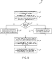
- FIG. 9 illustrates a flow diagram of an example process 900 for determining a resource from different resource sets configured for different CORESET/search space configurations in accordance with one or more implementations.
- the process 900 is primarily described herein with reference to the receiver 220 of the wireless communication device 200 of FIG. 2 .
- the process 900 is not limited to the receiver 220 of the wireless communication device 200 of FIG. 2 , and one or more blocks (or operations) of the process 900 may be performed by one or more other components or chips of the wireless communication device 200.
- the wireless communication device 200 also is presented as an exemplary device and the operations described herein may be performed by any suitable device, such as one or more of the wireless communication devices 118-132.
- the blocks of the process 900 are described herein as occurring in serial, or linearly. However, multiple blocks of the process 900 may occur in parallel. In addition, the blocks of the process 900 need not be performed in the order shown and/or one or more blocks of the process 900 need not be performed and/or can be replaced by other operations.
- the process 900 starts at step 901, where a station (e.g., 128, 200) obtains a configuration associated with a PHY channel.
- the station determines that the configuration includes a CORESET/search space configuration by receiving a message from a base station (e.g., 116) indicating that a received frame includes a CORESET/search space configuration for resource allocation scheduling.
- the received frame is a downlink frame associated with a downlink transmission with the base station.
- the received frame may include a PHY channel/signal (e.g., PDSCH, PDCCH).
- the CORESET/search space configuration is associated with the resource allocation scheduling for a downlink transmission.
- the station determines whether the received frame is configured with a first CORESET/search space configuration or a second CORESET/search space configuration. In some examples, the station also determines a periodicity configuration and/or time position associated with the CORESET/search space configuration. If the received frame is configured with the first CORESET/search space configuration, then the process 900 proceeds to step 904. Otherwise, the process 900 proceeds to step 905.
- the station selects a set of resources corresponding to the first CORESET/search space configuration.
- the station selects a set of resources corresponding to the second CORESET/search space configuration.
- the station determines an actual resource from the selected set of resources. In some aspects, the station performs the selection using an indication included in a second message received from the base station. In other aspects, the station may perform the selection based on an implicit mapping of other PHY channels or signals with one or more resources of the selected set of resources such that an unmapped resource may be derived.
- the station causes its transceiver (e.g., 205) to either receive a PDSCH signal or transmit a PUSCH signal, for example, on the determined actual resource.
- different sets of resources are configured for different CORESET/search space configurations, e.g. their periodicity configurations and/or time position.
- a station can at first select the resource set(s) corresponding to a particular CORESET/search space configuration, then determine the actual resource used for the transmission of a PHY channel or signal. If based on a certain DCI overhead, N resources can be configured for the first CORESET/search space configuration and the second CORESET/search space configuration, respectively.
- this approach can double the number of candidate resources available for resource allocation scheduling, and helps achieve substantially larger flexibility in resource allocation scheduling than the legacy approach (e.g., 4GLTE) without any additional PHY signaling overhead cost.
- FIG. 10 conceptually illustrates an electronic system 1000 with which one or more implementations of the subject technology may be implemented.
- the electronic system 1000 can be a network device, a media converter, a desktop computer, a laptop computer, a tablet computer, a server, a switch, a router, a base station, a receiver, a phone, or generally any electronic device that transmits signals over a network.
- Such an electronic system 1000 includes various types of computer readable media and interfaces for various other types of computer readable media.
- the electronic system 1000 is, or includes, one or more of the wireless communication devices 118-132.
- the electronic system 1000 includes a bus 1008, one or more processing unit(s) 1012, a system memory 1004, a read-only memory (ROM) 1010, a permanent storage device 1002, an input device interface 1014, an output device interface 1006, and a network interface 1016, or subsets and variations thereof.
- a bus 1008 one or more processing unit(s) 1012
- a system memory 1004 a read-only memory (ROM) 1010
- ROM read-only memory
- Permanent storage device 1002 an input device interface 1014
- an output device interface 1006 and a network interface 1016, or subsets and variations thereof.
- the bus 1008 collectively represents all system, peripheral, and chipset buses that communicatively connect the numerous internal devices of the electronic system 1000.
- the bus 1008 communicatively connects the one or more processing unit(s) 1012 with the ROM 1010, the system memory 1004, and the permanent storage device 1002. From these various memory units, the one or more processing unit(s) 1012 retrieves instructions to execute and data to process in order to execute the processes of the subject disclosure.
- the one or more processing unit(s) 1012 can be a single processor or a multi-core processor in different implementations.
- the ROM 1010 stores static data and instructions that are needed by the one or more processing unit(s) 1012 and other modules of the electronic system.
- the permanent storage device 1002 is a read-and-write memory device.
- the permanent storage device 1002 is a non-volatile memory unit that stores instructions and data even when the electronic system 1000 is off.
- One or more implementations of the subject disclosure use a mass-storage device (such as a magnetic or optical disk and its corresponding disk drive) as the permanent storage device 1002.
- system memory 1004 is a read-and-write memory device. However, unlike the permanent storage device 1002, the system memory 1004 is a volatile read-and-write memory, such as random access memory.
- System memory 1004 stores any of the instructions and data that the one or more processing unit(s) 1012 needs at runtime. In one or more implementations, the processes of the subject disclosure are stored in the system memory 1004, the permanent storage device 1002, and/or the ROM 1010. From these various memory units, the one or more processing unit(s) 1012 retrieves instructions to execute and data to process in order to execute the processes of one or more implementations.
- the bus 1008 also connects to the input device interface 1014 and the output device interface 1006.
- the input device interface 1014 enables a user to communicate information and select commands to the electronic system.
- Input devices used with the input device interface 1014 include, for example, alphanumeric keyboards and pointing devices (also called “cursor control devices").
- the output device interface 1006 enables, for example, the display of images generated by the electronic system 1000.
- Output devices used with the output device interface 1006 include, for example, printers and display devices, such as a liquid crystal display (LCD), a light emitting diode (LED) display, an organic light emitting diode (OLED) display, a flexible display, a flat panel display, a solid state display, a projector, or any other device for outputting information.
- printers and display devices such as a liquid crystal display (LCD), a light emitting diode (LED) display, an organic light emitting diode (OLED) display, a flexible display, a flat panel display, a solid state display, a projector, or any other device for outputting information.
- One or more implementations include devices that function as both input and output devices, such as a touchscreen.
- feedback provided to the user can be any form of sensory feedback, such as visual feedback, auditory feedback, or tactile feedback; and input from the user can be received in any form, including acoustic, speech, or tactile input.
- the bus 1008 also couples the electronic system 1000 to one or more networks (not shown) through one or more network interfaces 1016.
- the computer can be a part of one or more network of computers (such as a local area network (“LAN”), a wide area network (“WAN”), or an Intranet, or a network of networks, such as the Internet. Any or all components of the electronic system 1000 can be used in conjunction with the subject disclosure.
- a method may be an operation, an instruction, or a function and vice versa.
- Implementations within the scope of the present disclosure can be partially or entirely realized using a tangible computer-readable storage medium (or multiple tangible computer-readable storage media of one or more types) encoding one or more instructions.
- the tangible computer-readable storage medium also can be non-transitory in nature.
- the computer-readable storage medium can be any storage medium that can be read, written, or otherwise accessed by a general purpose or special purpose computing device, including any processing electronics and/or processing circuitry capable of executing instructions.
- the computer-readable medium can include any volatile semiconductor memory.
- the computer-readable medium also can include any non-volatile semiconductor memory.
- the computer-readable storage medium can include any non-semiconductor memory, such as optical disk storage, magnetic disk storage, magnetic tape, other magnetic storage devices, or any other medium capable of storing one or more instructions.
- the tangible computer-readable storage medium can be directly coupled to a computing device, while in other implementations, the tangible computer-readable storage medium can be indirectly coupled to a computing device, e.g., via one or more wired connections, one or more wireless connections, or any combination thereof.
- Instructions can be directly executable or can be used to develop executable instructions.
- instructions can be realized as executable or non-executable machine code or as instructions in a high-level language that can be compiled to produce executable or non-executable machine code.
- instructions also can be realized as or can include data.
- Computer-executable instructions also can be organized in any format, including routines, subroutines, programs, data structures, objects, modules, applications, applets, functions, etc. As recognized by those of skill in the art, details including, but not limited to, the number, structure, sequence, and organization of instructions can vary significantly without varying the underlying logic, function, processing, and output.
- ASICs application specific integrated circuits
- FPGAs field programmable gate arrays
- integrated circuits execute instructions that are stored on the circuit itself.
- any specific order or hierarchy of blocks in the processes disclosed is an illustration of example approaches. Based upon design preferences, it is understood that the specific order or hierarchy of blocks in the processes may be rearranged, or that all illustrated blocks be performed. Any of the blocks may be performed simultaneously. In one or more implementations, multitasking and parallel processing may be advantageous. Moreover, the separation of various system components described above should not be understood as requiring such separation in all aspects, and it should be understood that the described program components and systems can generally be integrated together in a single software product or packaged into multiple software products.
- base station As used in this specification and any claims of this application, the terms “base station”, “station”, “receiver”, “transmitter”, “computer”, “server”, “processor”, and “memory” all refer to electronic or other technological devices. These terms exclude people or groups of people.
- display or “displaying” means displaying on an electronic device.
- the phrase "at least one of' preceding a series of items, with the term “and” or “or” to separate any of the items, modifies the list as a whole, rather than each member of the list (e.g., each item).
- phrases “at least one of A, B, and C” or “at least one of A, B, or C” each refer to only A, only B, or only C; any combination of A, B, and C; and/or at least one of each of A, B, and C.
- a processor configured to monitor and control an operation or a component may also mean the processor being programmed to monitor and control the operation or the processor being operable to monitor and control the operation.
- a processor configured to execute code can be construed as a processor programmed to execute code or operable to execute code.
- phrases such as an aspect, the aspect, another aspect, some aspects, one or more aspects, an implementation, the implementation, another implementation, some implementations, one or more implementations, an embodiment, the embodiment, another embodiment, some embodiments, one or more embodiments, a configuration, the configuration, another configuration, some configurations, one or more configurations, the subject technology, the disclosure, the present disclosure, other variations thereof and alike are for convenience and do not imply that a disclosure relating to such phrase(s) is essential to the subject technology or that such disclosure applies to all configurations of the subject technology.
- a disclosure relating to such phrase(s) may apply to all configurations, or one or more configurations.
- a disclosure relating to such phrase(s) may provide one or more examples.
- a phrase such as an aspect or some aspects may refer to one or more aspects and vice versa, and this applies similarly to other foregoing phrases.
Landscapes
- Engineering & Computer Science (AREA)
- Signal Processing (AREA)
- Computer Networks & Wireless Communication (AREA)
- Mobile Radio Communication Systems (AREA)
Claims (9)
- Station de communication sans fil, la station comprenant :un émetteur-récepteur (205) ;une ou plusieurs mémoires (250) ; etun ou plusieurs processeurs (260) couplés aux une ou plusieurs mémoires (250), les un ou plusieurs processeurs (260) étant configurés pour :obtenir (401) une configuration associée à un canal de couche physique, PHY, dans lequel de multiples ensembles de ressources sont configurés pour le canal PHY, et différentes configurations correspondent à différents ensembles de ressources, dans lequel lorsque deux configurations d'un ensemble de ressources sont différentes, au moins une ressource dans un premier ensemble de ressources n'est pas comprise dans un deuxième ensemble de ressources, une ressource est configurée avec un ou de multiples paramètres dans le domaine temporel, le domaine fréquentiel, le domaine de code et/ou le domaine spatial et lorsque deux ressources sont différentes, une valeur d'au moins un paramètre est différente pour les deux ressources,sélectionner un ensemble de ressources correspondant à la configuration parmi une pluralité de ressources,déterminer (301) une ressource effective parmi l'ensemble de ressources sélectionné, etamener (302) l'émetteur-récepteur à émettre ou recevoir un signal PHY correspondant sur la ressource effective déterminée,dans lequel la configuration associée au canal PHY comprend une configuration de partie de bande passante, BWP,dans lequel l'émetteur-récepteur (205) est configuré pour recevoir un premier message, et dans lequel la configuration est obtenue en fonction du premier message, etdans lequel l'émetteur-récepteur (205) est configuré pour recevoir un second message et dans lequel la ressource effective est déterminée en fonction d'une indication incluse dans le second message.
- Station selon la revendication 1, dans laquelle différentes configurations correspondent à différents ensembles de ressources en ce que :
chaque configuration de BWP correspond à chaque ensemble de ressources. - Station selon la revendication 1, dans laquelle le canal PHY comprend un canal partagé de liaison descendante, DL, physique, PDSCH, un canal partagé de liaison montante, UL, physique, PUSCH, un canal de commande de DL physique, PDCCH, un canal de commande d'UL physique, PUCCH, et un canal d'accès aléatoire physique, PRACH.
- Procédé réalisé au niveau d'une station de communication sans fil comprenant :l'obtention (401) d'une configuration associée à un canal de couche physique, PHY, dans lequel de multiples ensembles de ressources sont configurés pour le canal PHY, et différentes configurations correspondent à différents ensembles de ressources, dans lequel lorsque deux configurations d'un ensemble de ressources sont différentes, au moins une ressource dans un premier ensemble de ressources n'est pas comprise dans un deuxième ensemble de ressources, une ressource est configurée avec un ou de multiples paramètres dans le domaine temporel, le domaine fréquentiel, le domaine de code et/ou le domaine spatial-domain et/ou spatial et lorsque deux ressources sont différentes, une valeur d'au moins un paramètre est différente pour les deux ressources ;la sélection d'un ensemble de ressources correspondant à la configuration parmi une pluralité de ressources ;la détermination (301) d'une ressource effective parmi l'ensemble de ressources sélectionné ; etl'émission ou la réception (302) d'un signal PHY correspondant sur la ressource effective déterminée,dans lequel la configuration associée au canal PHY comprend une configuration de partie de bande passante, BWP ;le procédé comprenant en outre :la réception d'un premier message, dans lequel la configuration est obtenue en fonction du premier message ;le procédé comprenant en outre :
la réception d'un second message, dans lequel la ressource effective est déterminée en fonction d'une indication incluse dans le second message. - Procédé selon la revendication 4, dans lequel différentes configurations correspondent à différents ensembles de ressources en ce que :
chaque configuration BWP correspond à chaque ensemble de ressources. - Procédé selon la revendication 4, dans lequel le canal PHY comprend un canal partagé de liaison descendante, DL, physique, PDSCH, un canal partagé de liaison montante, UL, physique, PUSCH, un canal de commande de DL physique, PDCCH, un canal de commande d'UL physique, PUCCH, et un canal d'accès aléatoire physique, PRACH.
- Support de stockage non transitoire lisible par ordinateur, caractérisé en ce que le support de stockage non transitoire lisible par ordinateur stocke des instructions exécutables par ordinateur qui, à leur exécution par un ou plusieurs processeurs, amènent les un ou plusieurs processeurs à réaliser les opérations suivantes :l'obtention (401) par une station de communication sans fil d'une configuration associée à un canal de couche physique, PHY,dans lequel de multiples ensembles de ressources sont configurés pour le canal PHY et différentes configurations correspondent à différents ensembles de ressources, dans lequel lorsque deux configurations d'un ensemble de ressources sont différentes, au moins une ressource d'un premier ensemble de ressources n'est pas comprise dans un deuxième ensemble de ressources, une ressource est configurée avec un ou plusieurs paramètres dans le domaine temporel, domaine fréquentiel, domaine de code et/ou domaine spatial ; et lorsque deux ressources sont différentes, une valeur d'au moins un paramètre est différente pour les deux ressources;la sélection d'un ensemble de ressources correspondant à la configuration parmi une pluralité de ressources ;la détermination (301) d'une ressource effective parmi l'ensemble de ressources sélectionné ; etl'émission ou la réception (302) d'un signal PHY correspondant sur la ressource effective déterminée,dans lequel la configuration associée au canal PHY comprend une configuration de partie de bande passante, BWP ;dans lequel le procédé comprend en outre :la réception d'un premier message, dans lequel la configuration est obtenue en fonction du premier message ;dans lequel le procédé comprend en outre :
la réception d'un second message, dans lequel la ressource effective est déterminée en fonction d'une indication incluse dans le second message. - Procédé selon la revendication 7, dans lequel différentes configurations correspondent à différents ensembles de ressources en ce que :
chaque configuration de BWP correspond à chaque ensemble de ressources. - Procédé selon la revendication 7, dans lequel le canal PHY comprend un canal partagé de liaison descendante, DL, physique, PDSCH, un canal partagé de liaison montante, UL, physique, PUSCH, un canal de commande de DL physique, PDCCH, un canal de commande d'UL physique, PUCCH, et un canal d'accès aléatoire physique, PRACH.
Applications Claiming Priority (2)
| Application Number | Priority Date | Filing Date | Title |
|---|---|---|---|
| US201762594107P | 2017-12-04 | 2017-12-04 | |
| PCT/CN2018/119232 WO2019109921A1 (fr) | 2017-12-04 | 2018-12-04 | Configuration d'ensemble de ressources multiples |
Publications (3)
| Publication Number | Publication Date |
|---|---|
| EP3718277A1 EP3718277A1 (fr) | 2020-10-07 |
| EP3718277A4 EP3718277A4 (fr) | 2021-03-03 |
| EP3718277B1 true EP3718277B1 (fr) | 2022-06-22 |
Family
ID=66751296
Family Applications (1)
| Application Number | Title | Priority Date | Filing Date |
|---|---|---|---|
| EP18885826.0A Active EP3718277B1 (fr) | 2017-12-04 | 2018-12-04 | Configuration d'ensemble de ressources multiples |
Country Status (7)
| Country | Link |
|---|---|
| US (1) | US11246127B2 (fr) |
| EP (1) | EP3718277B1 (fr) |
| JP (1) | JP2021506155A (fr) |
| KR (1) | KR20200091449A (fr) |
| CN (2) | CN111641578B (fr) |
| AU (1) | AU2018381739A1 (fr) |
| WO (1) | WO2019109921A1 (fr) |
Families Citing this family (5)
| Publication number | Priority date | Publication date | Assignee | Title |
|---|---|---|---|---|
| US11595236B2 (en) * | 2019-08-16 | 2023-02-28 | Qualcomm Incorporated | Techniques for demodulation reference signal time domain pattern configuration |
| WO2021189213A1 (fr) * | 2020-03-23 | 2021-09-30 | 华为技术有限公司 | Procédés et appareil d'envoi et de réception d'informations de commande |
| US11877292B2 (en) * | 2020-07-29 | 2024-01-16 | Qualcomm Incorporated | Techniques for activating and releasing resources across multiple component carriers |
| WO2022027485A1 (fr) * | 2020-08-06 | 2022-02-10 | Nec Corporation | Procédés de communication, dispositif terminal, dispositif de réseau et supports lisibles par ordinateur |
| AU2020471536A1 (en) * | 2020-10-09 | 2023-06-15 | Zte Corporation | Scheduling resource mapping of inter-cell multi transmission/reception point operation |
Family Cites Families (17)
| Publication number | Priority date | Publication date | Assignee | Title |
|---|---|---|---|---|
| US9215058B2 (en) | 2012-03-06 | 2015-12-15 | Blackberry Limited | Enhanced PHICH transmission for LTE-advanced |
| CN103581094B (zh) * | 2012-07-24 | 2016-12-28 | 电信科学技术研究院 | 下行用户专用解调参考信号的传输方法和设备 |
| US9769810B2 (en) * | 2012-07-30 | 2017-09-19 | Sharp Kabushiki Kaisha | Base station device, mobile station device, communication method, and integrated circuit |
| US9686677B2 (en) | 2013-01-17 | 2017-06-20 | Intel IP Corporation | Techniques for deploying small cells as secondary cells for user equipment |
| WO2014113084A1 (fr) | 2013-01-17 | 2014-07-24 | Intel IP Corporation | Systèmes et procédés pour un déchargement de trafic efficace sans perturbation de service |
| EP2946606A4 (fr) | 2013-01-17 | 2016-12-21 | Intel Ip Corp | Signal de découverte dans une petite cellule en grappe |
| WO2014113078A1 (fr) | 2013-01-17 | 2014-07-24 | Intel IP Corporation | Mappage de sous-trames spéciales dans un réseau de communication sans fil |
| US9313802B2 (en) | 2013-01-17 | 2016-04-12 | Intel IP Corporation | Communication of security key information |
| WO2014113072A1 (fr) | 2013-01-17 | 2014-07-24 | Intel IP Corporation | Partitionnement centralisé de dispositifs d'utilisateurs dans un réseau sans fil hétérogène |
| US9525538B2 (en) | 2013-01-17 | 2016-12-20 | Intel IP Corporation | Apparatus, system and method of communicating non-cellular access network information over a cellular network |
| CN105009511B (zh) | 2013-01-17 | 2020-07-03 | 苹果公司 | 一种可用于充当呈现实体的用户设备和一种呈现服务器 |
| CN105009478B (zh) | 2013-01-17 | 2018-05-25 | 英特尔Ip公司 | 用于扩展不连续接收的技术和系统 |
| EP2946590B1 (fr) | 2013-01-17 | 2020-12-30 | Apple Inc. | Procédé, appareil et système de gestion d'interférence de coexistence à l'intérieur d'un dispositif dans un réseau sans fil |
| CN104009827B (zh) * | 2013-02-22 | 2019-05-21 | 电信科学技术研究院 | 一种用户设备专用解调参考信号的传输方法及设备 |
| CN107294682A (zh) * | 2016-04-01 | 2017-10-24 | 中兴通讯股份有限公司 | Dmrs的发送方法及装置 |
| EP3662711A4 (fr) * | 2017-08-02 | 2021-02-17 | Intel IP Corporation | Appareil, système et procédé de mise en oeuvre de ressources réservées pour une compatibilité ascendante dans des réseaux de nouvelle radio (nr) |
| US10666480B2 (en) * | 2017-11-16 | 2020-05-26 | Ofinno, Llc | Bandwidth part slot format indication |
-
2018
- 2018-12-04 AU AU2018381739A patent/AU2018381739A1/en not_active Abandoned
- 2018-12-04 KR KR1020207019359A patent/KR20200091449A/ko not_active Application Discontinuation
- 2018-12-04 EP EP18885826.0A patent/EP3718277B1/fr active Active
- 2018-12-04 CN CN202010424068.8A patent/CN111641578B/zh active Active
- 2018-12-04 JP JP2020530360A patent/JP2021506155A/ja not_active Withdrawn
- 2018-12-04 WO PCT/CN2018/119232 patent/WO2019109921A1/fr unknown
- 2018-12-04 CN CN201880065850.6A patent/CN111201761A/zh active Pending
-
2020
- 2020-05-27 US US16/884,924 patent/US11246127B2/en active Active
Also Published As
| Publication number | Publication date |
|---|---|
| WO2019109921A1 (fr) | 2019-06-13 |
| US11246127B2 (en) | 2022-02-08 |
| JP2021506155A (ja) | 2021-02-18 |
| CN111201761A (zh) | 2020-05-26 |
| EP3718277A1 (fr) | 2020-10-07 |
| KR20200091449A (ko) | 2020-07-30 |
| CN111641578A (zh) | 2020-09-08 |
| EP3718277A4 (fr) | 2021-03-03 |
| AU2018381739A1 (en) | 2020-07-23 |
| US20200288449A1 (en) | 2020-09-10 |
| CN111641578B (zh) | 2023-01-24 |
Similar Documents
| Publication | Publication Date | Title |
|---|---|---|
| EP3718277B1 (fr) | Configuration d'ensemble de ressources multiples | |
| US11659528B2 (en) | Coordinated wireless communications using multiple transmission time intervals | |
| US20240023105A1 (en) | Techniques for configuring uplink channels in unlicensed radio frequency spectrum bands | |
| US10764873B2 (en) | Method and device for channel selection | |
| US10367616B2 (en) | Dynamic sounding reference signal scheduling | |
| EP2793520B1 (fr) | Procédé et appareil de communications sans fil | |
| US8730895B2 (en) | Method for aperiodic SRS subframe configuration and signaling | |
| US10555331B2 (en) | Nested system operation | |
| EP3528536A1 (fr) | Procédé et appareil de communication sans fil | |
| EP3493589A1 (fr) | Procédé et appareil d'envoi de signal de référence et procédé et appareil de réception de signal de référence | |
| US10637622B2 (en) | Common reference signals for multiple search spaces within a control resource set | |
| WO2018205874A1 (fr) | Procédé de transmission, terminal et dispositif de réseau | |
| US20220217705A1 (en) | Ue capability information for a unified tci framework | |
| US20200187238A1 (en) | Methods and apparatuses for control resource mapping | |
| US9900216B2 (en) | Handling of different control channel configurations for one or more wireless devices in a radio network | |
| US20220272754A1 (en) | Method and Apparatus for Sharing Channel Occupancy Time | |
| WO2018228496A1 (fr) | Procédé d'indication, procédé de traitement et appareil | |
| US11962521B2 (en) | Radio communication apparatus, method, program, non-transitory computer readable recording medium, and system | |
| WO2018023510A1 (fr) | Transmission de signaux de référence de démodulation de liaison montante dans des uppts | |
| WO2020155106A1 (fr) | Communications à large bande basées sur une évaluation de disponibilité | |
| WO2017028000A1 (fr) | Émission de signal de découverte sur un spectre non autorisé |
Legal Events
| Date | Code | Title | Description |
|---|---|---|---|
| STAA | Information on the status of an ep patent application or granted ep patent |
Free format text: STATUS: THE INTERNATIONAL PUBLICATION HAS BEEN MADE |
|
| PUAI | Public reference made under article 153(3) epc to a published international application that has entered the european phase |
Free format text: ORIGINAL CODE: 0009012 |
|
| STAA | Information on the status of an ep patent application or granted ep patent |
Free format text: STATUS: REQUEST FOR EXAMINATION WAS MADE |
|
| 17P | Request for examination filed |
Effective date: 20200703 |
|
| AK | Designated contracting states |
Kind code of ref document: A1 Designated state(s): AL AT BE BG CH CY CZ DE DK EE ES FI FR GB GR HR HU IE IS IT LI LT LU LV MC MK MT NL NO PL PT RO RS SE SI SK SM TR |
|
| AX | Request for extension of the european patent |
Extension state: BA ME |
|
| A4 | Supplementary search report drawn up and despatched |
Effective date: 20210129 |
|
| RIC1 | Information provided on ipc code assigned before grant |
Ipc: H04L 5/00 20060101ALI20210125BHEP Ipc: H04W 72/00 20090101ALI20210125BHEP Ipc: H04L 27/26 20060101AFI20210125BHEP |
|
| DAV | Request for validation of the european patent (deleted) | ||
| DAX | Request for extension of the european patent (deleted) | ||
| STAA | Information on the status of an ep patent application or granted ep patent |
Free format text: STATUS: EXAMINATION IS IN PROGRESS |
|
| 17Q | First examination report despatched |
Effective date: 20211022 |
|
| GRAP | Despatch of communication of intention to grant a patent |
Free format text: ORIGINAL CODE: EPIDOSNIGR1 |
|
| STAA | Information on the status of an ep patent application or granted ep patent |
Free format text: STATUS: GRANT OF PATENT IS INTENDED |
|
| INTG | Intention to grant announced |
Effective date: 20220406 |
|
| GRAS | Grant fee paid |
Free format text: ORIGINAL CODE: EPIDOSNIGR3 |
|
| GRAA | (expected) grant |
Free format text: ORIGINAL CODE: 0009210 |
|
| STAA | Information on the status of an ep patent application or granted ep patent |
Free format text: STATUS: THE PATENT HAS BEEN GRANTED |
|
| AK | Designated contracting states |
Kind code of ref document: B1 Designated state(s): AL AT BE BG CH CY CZ DE DK EE ES FI FR GB GR HR HU IE IS IT LI LT LU LV MC MK MT NL NO PL PT RO RS SE SI SK SM TR |
|
| REG | Reference to a national code |
Ref country code: GB Ref legal event code: FG4D |
|
| REG | Reference to a national code |
Ref country code: CH Ref legal event code: EP |
|
| REG | Reference to a national code |
Ref country code: DE Ref legal event code: R096 Ref document number: 602018037162 Country of ref document: DE |
|
| REG | Reference to a national code |
Ref country code: AT Ref legal event code: REF Ref document number: 1500525 Country of ref document: AT Kind code of ref document: T Effective date: 20220715 |
|
| REG | Reference to a national code |
Ref country code: IE Ref legal event code: FG4D |
|
| REG | Reference to a national code |
Ref country code: LT Ref legal event code: MG9D |
|
| REG | Reference to a national code |
Ref country code: NL Ref legal event code: MP Effective date: 20220622 |
|
| PG25 | Lapsed in a contracting state [announced via postgrant information from national office to epo] |
Ref country code: SE Free format text: LAPSE BECAUSE OF FAILURE TO SUBMIT A TRANSLATION OF THE DESCRIPTION OR TO PAY THE FEE WITHIN THE PRESCRIBED TIME-LIMIT Effective date: 20220622 Ref country code: NO Free format text: LAPSE BECAUSE OF FAILURE TO SUBMIT A TRANSLATION OF THE DESCRIPTION OR TO PAY THE FEE WITHIN THE PRESCRIBED TIME-LIMIT Effective date: 20220922 Ref country code: LT Free format text: LAPSE BECAUSE OF FAILURE TO SUBMIT A TRANSLATION OF THE DESCRIPTION OR TO PAY THE FEE WITHIN THE PRESCRIBED TIME-LIMIT Effective date: 20220622 Ref country code: HR Free format text: LAPSE BECAUSE OF FAILURE TO SUBMIT A TRANSLATION OF THE DESCRIPTION OR TO PAY THE FEE WITHIN THE PRESCRIBED TIME-LIMIT Effective date: 20220622 Ref country code: GR Free format text: LAPSE BECAUSE OF FAILURE TO SUBMIT A TRANSLATION OF THE DESCRIPTION OR TO PAY THE FEE WITHIN THE PRESCRIBED TIME-LIMIT Effective date: 20220923 Ref country code: FI Free format text: LAPSE BECAUSE OF FAILURE TO SUBMIT A TRANSLATION OF THE DESCRIPTION OR TO PAY THE FEE WITHIN THE PRESCRIBED TIME-LIMIT Effective date: 20220622 Ref country code: BG Free format text: LAPSE BECAUSE OF FAILURE TO SUBMIT A TRANSLATION OF THE DESCRIPTION OR TO PAY THE FEE WITHIN THE PRESCRIBED TIME-LIMIT Effective date: 20220922 |
|
| REG | Reference to a national code |
Ref country code: AT Ref legal event code: MK05 Ref document number: 1500525 Country of ref document: AT Kind code of ref document: T Effective date: 20220622 |
|
| PG25 | Lapsed in a contracting state [announced via postgrant information from national office to epo] |
Ref country code: RS Free format text: LAPSE BECAUSE OF FAILURE TO SUBMIT A TRANSLATION OF THE DESCRIPTION OR TO PAY THE FEE WITHIN THE PRESCRIBED TIME-LIMIT Effective date: 20220622 Ref country code: LV Free format text: LAPSE BECAUSE OF FAILURE TO SUBMIT A TRANSLATION OF THE DESCRIPTION OR TO PAY THE FEE WITHIN THE PRESCRIBED TIME-LIMIT Effective date: 20220622 |
|
| PG25 | Lapsed in a contracting state [announced via postgrant information from national office to epo] |
Ref country code: NL Free format text: LAPSE BECAUSE OF FAILURE TO SUBMIT A TRANSLATION OF THE DESCRIPTION OR TO PAY THE FEE WITHIN THE PRESCRIBED TIME-LIMIT Effective date: 20220622 |
|
| PG25 | Lapsed in a contracting state [announced via postgrant information from national office to epo] |
Ref country code: SM Free format text: LAPSE BECAUSE OF FAILURE TO SUBMIT A TRANSLATION OF THE DESCRIPTION OR TO PAY THE FEE WITHIN THE PRESCRIBED TIME-LIMIT Effective date: 20220622 Ref country code: SK Free format text: LAPSE BECAUSE OF FAILURE TO SUBMIT A TRANSLATION OF THE DESCRIPTION OR TO PAY THE FEE WITHIN THE PRESCRIBED TIME-LIMIT Effective date: 20220622 Ref country code: RO Free format text: LAPSE BECAUSE OF FAILURE TO SUBMIT A TRANSLATION OF THE DESCRIPTION OR TO PAY THE FEE WITHIN THE PRESCRIBED TIME-LIMIT Effective date: 20220622 Ref country code: PT Free format text: LAPSE BECAUSE OF FAILURE TO SUBMIT A TRANSLATION OF THE DESCRIPTION OR TO PAY THE FEE WITHIN THE PRESCRIBED TIME-LIMIT Effective date: 20221024 Ref country code: ES Free format text: LAPSE BECAUSE OF FAILURE TO SUBMIT A TRANSLATION OF THE DESCRIPTION OR TO PAY THE FEE WITHIN THE PRESCRIBED TIME-LIMIT Effective date: 20220622 Ref country code: EE Free format text: LAPSE BECAUSE OF FAILURE TO SUBMIT A TRANSLATION OF THE DESCRIPTION OR TO PAY THE FEE WITHIN THE PRESCRIBED TIME-LIMIT Effective date: 20220622 Ref country code: CZ Free format text: LAPSE BECAUSE OF FAILURE TO SUBMIT A TRANSLATION OF THE DESCRIPTION OR TO PAY THE FEE WITHIN THE PRESCRIBED TIME-LIMIT Effective date: 20220622 Ref country code: AT Free format text: LAPSE BECAUSE OF FAILURE TO SUBMIT A TRANSLATION OF THE DESCRIPTION OR TO PAY THE FEE WITHIN THE PRESCRIBED TIME-LIMIT Effective date: 20220622 |
|
| PG25 | Lapsed in a contracting state [announced via postgrant information from national office to epo] |
Ref country code: PL Free format text: LAPSE BECAUSE OF FAILURE TO SUBMIT A TRANSLATION OF THE DESCRIPTION OR TO PAY THE FEE WITHIN THE PRESCRIBED TIME-LIMIT Effective date: 20220622 Ref country code: IS Free format text: LAPSE BECAUSE OF FAILURE TO SUBMIT A TRANSLATION OF THE DESCRIPTION OR TO PAY THE FEE WITHIN THE PRESCRIBED TIME-LIMIT Effective date: 20221022 |
|
| REG | Reference to a national code |
Ref country code: DE Ref legal event code: R097 Ref document number: 602018037162 Country of ref document: DE |
|
| PG25 | Lapsed in a contracting state [announced via postgrant information from national office to epo] |
Ref country code: AL Free format text: LAPSE BECAUSE OF FAILURE TO SUBMIT A TRANSLATION OF THE DESCRIPTION OR TO PAY THE FEE WITHIN THE PRESCRIBED TIME-LIMIT Effective date: 20220622 |
|
| PG25 | Lapsed in a contracting state [announced via postgrant information from national office to epo] |
Ref country code: DK Free format text: LAPSE BECAUSE OF FAILURE TO SUBMIT A TRANSLATION OF THE DESCRIPTION OR TO PAY THE FEE WITHIN THE PRESCRIBED TIME-LIMIT Effective date: 20220622 |
|
| PLBE | No opposition filed within time limit |
Free format text: ORIGINAL CODE: 0009261 |
|
| STAA | Information on the status of an ep patent application or granted ep patent |
Free format text: STATUS: NO OPPOSITION FILED WITHIN TIME LIMIT |
|
| 26N | No opposition filed |
Effective date: 20230323 |
|
| P01 | Opt-out of the competence of the unified patent court (upc) registered |
Effective date: 20230412 |
|
| REG | Reference to a national code |
Ref country code: DE Ref legal event code: R119 Ref document number: 602018037162 Country of ref document: DE |
|
| REG | Reference to a national code |
Ref country code: CH Ref legal event code: PL |
|
| GBPC | Gb: european patent ceased through non-payment of renewal fee |
Effective date: 20221204 |
|
| REG | Reference to a national code |
Ref country code: BE Ref legal event code: MM Effective date: 20221231 |
|
| PG25 | Lapsed in a contracting state [announced via postgrant information from national office to epo] |
Ref country code: SI Free format text: LAPSE BECAUSE OF FAILURE TO SUBMIT A TRANSLATION OF THE DESCRIPTION OR TO PAY THE FEE WITHIN THE PRESCRIBED TIME-LIMIT Effective date: 20220622 Ref country code: LU Free format text: LAPSE BECAUSE OF NON-PAYMENT OF DUE FEES Effective date: 20221204 |
|
| PG25 | Lapsed in a contracting state [announced via postgrant information from national office to epo] |
Ref country code: LI Free format text: LAPSE BECAUSE OF NON-PAYMENT OF DUE FEES Effective date: 20221231 Ref country code: IE Free format text: LAPSE BECAUSE OF NON-PAYMENT OF DUE FEES Effective date: 20221204 Ref country code: GB Free format text: LAPSE BECAUSE OF NON-PAYMENT OF DUE FEES Effective date: 20221204 Ref country code: DE Free format text: LAPSE BECAUSE OF NON-PAYMENT OF DUE FEES Effective date: 20230701 Ref country code: CH Free format text: LAPSE BECAUSE OF NON-PAYMENT OF DUE FEES Effective date: 20221231 |
|
| PG25 | Lapsed in a contracting state [announced via postgrant information from national office to epo] |
Ref country code: FR Free format text: LAPSE BECAUSE OF NON-PAYMENT OF DUE FEES Effective date: 20221231 Ref country code: BE Free format text: LAPSE BECAUSE OF NON-PAYMENT OF DUE FEES Effective date: 20221231 |
|
| PG25 | Lapsed in a contracting state [announced via postgrant information from national office to epo] |
Ref country code: IT Free format text: LAPSE BECAUSE OF FAILURE TO SUBMIT A TRANSLATION OF THE DESCRIPTION OR TO PAY THE FEE WITHIN THE PRESCRIBED TIME-LIMIT Effective date: 20220622 |
|
| PG25 | Lapsed in a contracting state [announced via postgrant information from national office to epo] |
Ref country code: CY Free format text: LAPSE BECAUSE OF FAILURE TO SUBMIT A TRANSLATION OF THE DESCRIPTION OR TO PAY THE FEE WITHIN THE PRESCRIBED TIME-LIMIT Effective date: 20220622 |