EP3718147B1 - Improvements to solar panels and harvesting of solar derived energy - Google Patents
Improvements to solar panels and harvesting of solar derived energy Download PDFInfo
- Publication number
- EP3718147B1 EP3718147B1 EP18883857.7A EP18883857A EP3718147B1 EP 3718147 B1 EP3718147 B1 EP 3718147B1 EP 18883857 A EP18883857 A EP 18883857A EP 3718147 B1 EP3718147 B1 EP 3718147B1
- Authority
- EP
- European Patent Office
- Prior art keywords
- air
- panel
- pvt
- solar
- jets
- Prior art date
- Legal status (The legal status is an assumption and is not a legal conclusion. Google has not performed a legal analysis and makes no representation as to the accuracy of the status listed.)
- Active
Links
Images


Classifications
-
- F—MECHANICAL ENGINEERING; LIGHTING; HEATING; WEAPONS; BLASTING
- F28—HEAT EXCHANGE IN GENERAL
- F28F—DETAILS OF HEAT-EXCHANGE AND HEAT-TRANSFER APPARATUS, OF GENERAL APPLICATION
- F28F3/00—Plate-like or laminated elements; Assemblies of plate-like or laminated elements
- F28F3/12—Elements constructed in the shape of a hollow panel, e.g. with channels
-
- F—MECHANICAL ENGINEERING; LIGHTING; HEATING; WEAPONS; BLASTING
- F24—HEATING; RANGES; VENTILATING
- F24S—SOLAR HEAT COLLECTORS; SOLAR HEAT SYSTEMS
- F24S10/00—Solar heat collectors using working fluids
- F24S10/40—Solar heat collectors using working fluids in absorbing elements surrounded by transparent enclosures, e.g. evacuated solar collectors
-
- F—MECHANICAL ENGINEERING; LIGHTING; HEATING; WEAPONS; BLASTING
- F24—HEATING; RANGES; VENTILATING
- F24S—SOLAR HEAT COLLECTORS; SOLAR HEAT SYSTEMS
- F24S10/00—Solar heat collectors using working fluids
- F24S10/50—Solar heat collectors using working fluids the working fluids being conveyed between plates
-
- F—MECHANICAL ENGINEERING; LIGHTING; HEATING; WEAPONS; BLASTING
- F24—HEATING; RANGES; VENTILATING
- F24S—SOLAR HEAT COLLECTORS; SOLAR HEAT SYSTEMS
- F24S10/00—Solar heat collectors using working fluids
- F24S10/70—Solar heat collectors using working fluids the working fluids being conveyed through tubular absorbing conduits
- F24S10/74—Solar heat collectors using working fluids the working fluids being conveyed through tubular absorbing conduits the tubular conduits are not fixed to heat absorbing plates and are not touching each other
- F24S10/742—Solar heat collectors using working fluids the working fluids being conveyed through tubular absorbing conduits the tubular conduits are not fixed to heat absorbing plates and are not touching each other the conduits being parallel to each other
-
- F—MECHANICAL ENGINEERING; LIGHTING; HEATING; WEAPONS; BLASTING
- F24—HEATING; RANGES; VENTILATING
- F24S—SOLAR HEAT COLLECTORS; SOLAR HEAT SYSTEMS
- F24S40/00—Safety or protection arrangements of solar heat collectors; Preventing malfunction of solar heat collectors
- F24S40/40—Preventing corrosion; Protecting against dirt or contamination
- F24S40/42—Preventing condensation inside solar modules
-
- F—MECHANICAL ENGINEERING; LIGHTING; HEATING; WEAPONS; BLASTING
- F24—HEATING; RANGES; VENTILATING
- F24S—SOLAR HEAT COLLECTORS; SOLAR HEAT SYSTEMS
- F24S80/00—Details, accessories or component parts of solar heat collectors not provided for in groups F24S10/00-F24S70/00
- F24S80/30—Arrangements for connecting the fluid circuits of solar collectors with each other or with other components, e.g. pipe connections; Fluid distributing means, e.g. headers
-
- F—MECHANICAL ENGINEERING; LIGHTING; HEATING; WEAPONS; BLASTING
- F28—HEAT EXCHANGE IN GENERAL
- F28F—DETAILS OF HEAT-EXCHANGE AND HEAT-TRANSFER APPARATUS, OF GENERAL APPLICATION
- F28F7/00—Elements not covered by group F28F1/00, F28F3/00 or F28F5/00
- F28F7/02—Blocks traversed by passages for heat-exchange media
-
- H—ELECTRICITY
- H02—GENERATION; CONVERSION OR DISTRIBUTION OF ELECTRIC POWER
- H02S—GENERATION OF ELECTRIC POWER BY CONVERSION OF INFRARED RADIATION, VISIBLE LIGHT OR ULTRAVIOLET LIGHT, e.g. USING PHOTOVOLTAIC [PV] MODULES
- H02S20/00—Supporting structures for PV modules
- H02S20/20—Supporting structures directly fixed to an immovable object
- H02S20/22—Supporting structures directly fixed to an immovable object specially adapted for buildings
- H02S20/23—Supporting structures directly fixed to an immovable object specially adapted for buildings specially adapted for roof structures
-
- H—ELECTRICITY
- H02—GENERATION; CONVERSION OR DISTRIBUTION OF ELECTRIC POWER
- H02S—GENERATION OF ELECTRIC POWER BY CONVERSION OF INFRARED RADIATION, VISIBLE LIGHT OR ULTRAVIOLET LIGHT, e.g. USING PHOTOVOLTAIC [PV] MODULES
- H02S30/00—Structural details of PV modules other than those related to light conversion
- H02S30/20—Collapsible or foldable PV modules
-
- H—ELECTRICITY
- H02—GENERATION; CONVERSION OR DISTRIBUTION OF ELECTRIC POWER
- H02S—GENERATION OF ELECTRIC POWER BY CONVERSION OF INFRARED RADIATION, VISIBLE LIGHT OR ULTRAVIOLET LIGHT, e.g. USING PHOTOVOLTAIC [PV] MODULES
- H02S40/00—Components or accessories in combination with PV modules, not provided for in groups H02S10/00 - H02S30/00
- H02S40/30—Electrical components
- H02S40/32—Electrical components comprising DC/AC inverter means associated with the PV module itself, e.g. AC modules
-
- H—ELECTRICITY
- H02—GENERATION; CONVERSION OR DISTRIBUTION OF ELECTRIC POWER
- H02S—GENERATION OF ELECTRIC POWER BY CONVERSION OF INFRARED RADIATION, VISIBLE LIGHT OR ULTRAVIOLET LIGHT, e.g. USING PHOTOVOLTAIC [PV] MODULES
- H02S40/00—Components or accessories in combination with PV modules, not provided for in groups H02S10/00 - H02S30/00
- H02S40/40—Thermal components
- H02S40/42—Cooling means
- H02S40/425—Cooling means using a gaseous or a liquid coolant, e.g. air flow ventilation, water circulation
-
- H—ELECTRICITY
- H02—GENERATION; CONVERSION OR DISTRIBUTION OF ELECTRIC POWER
- H02S—GENERATION OF ELECTRIC POWER BY CONVERSION OF INFRARED RADIATION, VISIBLE LIGHT OR ULTRAVIOLET LIGHT, e.g. USING PHOTOVOLTAIC [PV] MODULES
- H02S40/00—Components or accessories in combination with PV modules, not provided for in groups H02S10/00 - H02S30/00
- H02S40/40—Thermal components
- H02S40/44—Means to utilise heat energy, e.g. hybrid systems producing warm water and electricity at the same time
-
- H—ELECTRICITY
- H02—GENERATION; CONVERSION OR DISTRIBUTION OF ELECTRIC POWER
- H02S—GENERATION OF ELECTRIC POWER BY CONVERSION OF INFRARED RADIATION, VISIBLE LIGHT OR ULTRAVIOLET LIGHT, e.g. USING PHOTOVOLTAIC [PV] MODULES
- H02S50/00—Monitoring or testing of PV systems, e.g. load balancing or fault identification
-
- H—ELECTRICITY
- H10—SEMICONDUCTOR DEVICES; ELECTRIC SOLID-STATE DEVICES NOT OTHERWISE PROVIDED FOR
- H10F—INORGANIC SEMICONDUCTOR DEVICES SENSITIVE TO INFRARED RADIATION, LIGHT, ELECTROMAGNETIC RADIATION OF SHORTER WAVELENGTH OR CORPUSCULAR RADIATION
- H10F77/00—Constructional details of devices covered by this subclass
- H10F77/70—Surface textures, e.g. pyramid structures
- H10F77/703—Surface textures, e.g. pyramid structures of the semiconductor bodies, e.g. textured active layers
-
- F—MECHANICAL ENGINEERING; LIGHTING; HEATING; WEAPONS; BLASTING
- F24—HEATING; RANGES; VENTILATING
- F24S—SOLAR HEAT COLLECTORS; SOLAR HEAT SYSTEMS
- F24S10/00—Solar heat collectors using working fluids
-
- F—MECHANICAL ENGINEERING; LIGHTING; HEATING; WEAPONS; BLASTING
- F24—HEATING; RANGES; VENTILATING
- F24S—SOLAR HEAT COLLECTORS; SOLAR HEAT SYSTEMS
- F24S20/00—Solar heat collectors specially adapted for particular uses or environments
- F24S20/60—Solar heat collectors integrated in fixed constructions, e.g. in buildings
- F24S20/66—Solar heat collectors integrated in fixed constructions, e.g. in buildings in the form of facade constructions, e.g. wall constructions
-
- F—MECHANICAL ENGINEERING; LIGHTING; HEATING; WEAPONS; BLASTING
- F24—HEATING; RANGES; VENTILATING
- F24S—SOLAR HEAT COLLECTORS; SOLAR HEAT SYSTEMS
- F24S20/00—Solar heat collectors specially adapted for particular uses or environments
- F24S20/60—Solar heat collectors integrated in fixed constructions, e.g. in buildings
- F24S20/67—Solar heat collectors integrated in fixed constructions, e.g. in buildings in the form of roof constructions
-
- F—MECHANICAL ENGINEERING; LIGHTING; HEATING; WEAPONS; BLASTING
- F24—HEATING; RANGES; VENTILATING
- F24S—SOLAR HEAT COLLECTORS; SOLAR HEAT SYSTEMS
- F24S10/00—Solar heat collectors using working fluids
- F24S10/70—Solar heat collectors using working fluids the working fluids being conveyed through tubular absorbing conduits
- F24S2010/71—Solar heat collectors using working fluids the working fluids being conveyed through tubular absorbing conduits the conduits having a non-circular cross-section
-
- F—MECHANICAL ENGINEERING; LIGHTING; HEATING; WEAPONS; BLASTING
- F24—HEATING; RANGES; VENTILATING
- F24S—SOLAR HEAT COLLECTORS; SOLAR HEAT SYSTEMS
- F24S25/00—Arrangement of stationary mountings or supports for solar heat collector modules
- F24S2025/01—Special support components; Methods of use
- F24S2025/012—Foldable support elements
-
- F—MECHANICAL ENGINEERING; LIGHTING; HEATING; WEAPONS; BLASTING
- F24—HEATING; RANGES; VENTILATING
- F24S—SOLAR HEAT COLLECTORS; SOLAR HEAT SYSTEMS
- F24S80/00—Details, accessories or component parts of solar heat collectors not provided for in groups F24S10/00-F24S70/00
- F24S2080/03—Arrangements for heat transfer optimization
- F24S2080/05—Flow guiding means; Inserts inside conduits
-
- F—MECHANICAL ENGINEERING; LIGHTING; HEATING; WEAPONS; BLASTING
- F24—HEATING; RANGES; VENTILATING
- F24S—SOLAR HEAT COLLECTORS; SOLAR HEAT SYSTEMS
- F24S25/00—Arrangement of stationary mountings or supports for solar heat collector modules
-
- F—MECHANICAL ENGINEERING; LIGHTING; HEATING; WEAPONS; BLASTING
- F28—HEAT EXCHANGE IN GENERAL
- F28D—HEAT-EXCHANGE APPARATUS, NOT PROVIDED FOR IN ANOTHER SUBCLASS, IN WHICH THE HEAT-EXCHANGE MEDIA DO NOT COME INTO DIRECT CONTACT
- F28D21/00—Heat-exchange apparatus not covered by any of the groups F28D1/00 - F28D20/00
- F28D2021/0019—Other heat exchangers for particular applications; Heat exchange systems not otherwise provided for
- F28D2021/0028—Other heat exchangers for particular applications; Heat exchange systems not otherwise provided for for cooling heat generating elements, e.g. for cooling electronic components or electric devices
-
- H—ELECTRICITY
- H02—GENERATION; CONVERSION OR DISTRIBUTION OF ELECTRIC POWER
- H02S—GENERATION OF ELECTRIC POWER BY CONVERSION OF INFRARED RADIATION, VISIBLE LIGHT OR ULTRAVIOLET LIGHT, e.g. USING PHOTOVOLTAIC [PV] MODULES
- H02S20/00—Supporting structures for PV modules
- H02S20/20—Supporting structures directly fixed to an immovable object
- H02S20/22—Supporting structures directly fixed to an immovable object specially adapted for buildings
-
- H—ELECTRICITY
- H02—GENERATION; CONVERSION OR DISTRIBUTION OF ELECTRIC POWER
- H02S—GENERATION OF ELECTRIC POWER BY CONVERSION OF INFRARED RADIATION, VISIBLE LIGHT OR ULTRAVIOLET LIGHT, e.g. USING PHOTOVOLTAIC [PV] MODULES
- H02S20/00—Supporting structures for PV modules
- H02S20/30—Supporting structures being movable or adjustable, e.g. for angle adjustment
-
- Y—GENERAL TAGGING OF NEW TECHNOLOGICAL DEVELOPMENTS; GENERAL TAGGING OF CROSS-SECTIONAL TECHNOLOGIES SPANNING OVER SEVERAL SECTIONS OF THE IPC; TECHNICAL SUBJECTS COVERED BY FORMER USPC CROSS-REFERENCE ART COLLECTIONS [XRACs] AND DIGESTS
- Y02—TECHNOLOGIES OR APPLICATIONS FOR MITIGATION OR ADAPTATION AGAINST CLIMATE CHANGE
- Y02B—CLIMATE CHANGE MITIGATION TECHNOLOGIES RELATED TO BUILDINGS, e.g. HOUSING, HOUSE APPLIANCES OR RELATED END-USER APPLICATIONS
- Y02B10/00—Integration of renewable energy sources in buildings
- Y02B10/10—Photovoltaic [PV]
-
- Y—GENERAL TAGGING OF NEW TECHNOLOGICAL DEVELOPMENTS; GENERAL TAGGING OF CROSS-SECTIONAL TECHNOLOGIES SPANNING OVER SEVERAL SECTIONS OF THE IPC; TECHNICAL SUBJECTS COVERED BY FORMER USPC CROSS-REFERENCE ART COLLECTIONS [XRACs] AND DIGESTS
- Y02—TECHNOLOGIES OR APPLICATIONS FOR MITIGATION OR ADAPTATION AGAINST CLIMATE CHANGE
- Y02B—CLIMATE CHANGE MITIGATION TECHNOLOGIES RELATED TO BUILDINGS, e.g. HOUSING, HOUSE APPLIANCES OR RELATED END-USER APPLICATIONS
- Y02B10/00—Integration of renewable energy sources in buildings
- Y02B10/20—Solar thermal
-
- Y—GENERAL TAGGING OF NEW TECHNOLOGICAL DEVELOPMENTS; GENERAL TAGGING OF CROSS-SECTIONAL TECHNOLOGIES SPANNING OVER SEVERAL SECTIONS OF THE IPC; TECHNICAL SUBJECTS COVERED BY FORMER USPC CROSS-REFERENCE ART COLLECTIONS [XRACs] AND DIGESTS
- Y02—TECHNOLOGIES OR APPLICATIONS FOR MITIGATION OR ADAPTATION AGAINST CLIMATE CHANGE
- Y02E—REDUCTION OF GREENHOUSE GAS [GHG] EMISSIONS, RELATED TO ENERGY GENERATION, TRANSMISSION OR DISTRIBUTION
- Y02E10/00—Energy generation through renewable energy sources
- Y02E10/40—Solar thermal energy, e.g. solar towers
- Y02E10/44—Heat exchange systems
-
- Y—GENERAL TAGGING OF NEW TECHNOLOGICAL DEVELOPMENTS; GENERAL TAGGING OF CROSS-SECTIONAL TECHNOLOGIES SPANNING OVER SEVERAL SECTIONS OF THE IPC; TECHNICAL SUBJECTS COVERED BY FORMER USPC CROSS-REFERENCE ART COLLECTIONS [XRACs] AND DIGESTS
- Y02—TECHNOLOGIES OR APPLICATIONS FOR MITIGATION OR ADAPTATION AGAINST CLIMATE CHANGE
- Y02E—REDUCTION OF GREENHOUSE GAS [GHG] EMISSIONS, RELATED TO ENERGY GENERATION, TRANSMISSION OR DISTRIBUTION
- Y02E10/00—Energy generation through renewable energy sources
- Y02E10/50—Photovoltaic [PV] energy
-
- Y—GENERAL TAGGING OF NEW TECHNOLOGICAL DEVELOPMENTS; GENERAL TAGGING OF CROSS-SECTIONAL TECHNOLOGIES SPANNING OVER SEVERAL SECTIONS OF THE IPC; TECHNICAL SUBJECTS COVERED BY FORMER USPC CROSS-REFERENCE ART COLLECTIONS [XRACs] AND DIGESTS
- Y02—TECHNOLOGIES OR APPLICATIONS FOR MITIGATION OR ADAPTATION AGAINST CLIMATE CHANGE
- Y02E—REDUCTION OF GREENHOUSE GAS [GHG] EMISSIONS, RELATED TO ENERGY GENERATION, TRANSMISSION OR DISTRIBUTION
- Y02E10/00—Energy generation through renewable energy sources
- Y02E10/60—Thermal-PV hybrids
-
- Y—GENERAL TAGGING OF NEW TECHNOLOGICAL DEVELOPMENTS; GENERAL TAGGING OF CROSS-SECTIONAL TECHNOLOGIES SPANNING OVER SEVERAL SECTIONS OF THE IPC; TECHNICAL SUBJECTS COVERED BY FORMER USPC CROSS-REFERENCE ART COLLECTIONS [XRACs] AND DIGESTS
- Y02—TECHNOLOGIES OR APPLICATIONS FOR MITIGATION OR ADAPTATION AGAINST CLIMATE CHANGE
- Y02P—CLIMATE CHANGE MITIGATION TECHNOLOGIES IN THE PRODUCTION OR PROCESSING OF GOODS
- Y02P80/00—Climate change mitigation technologies for sector-wide applications
- Y02P80/20—Climate change mitigation technologies for sector-wide applications using renewable energy
Definitions
- the present invention relates a hybrid solar air photovoltaic thermal collector.
- Solar energy from the Sun is the primary driving force of all of earth's energy systems and humans have utilised the potential of such solar energy in an evolving manner for years; such as employing mirrors, optical lenses, solar heating, drying and more recently; solar air, hot water heaters and photo-voltaic (PV) cells/panels.
- PV photo-voltaic
- renewable energy e.g. wind, waves and geothermal
- Solar energy is well recognised as a resource that can be widely deployed globally and can be scaled from several watts to multi-megawatt installations using essentially the same solar panel concept. This is supported by evidence from some markets showing sustained year on year growth rates, and such growth has been reported to be in excess 30% compound annual growth rate (CAGR) for installed capacity of PV. Solar thermal hot water systems have been affordable and available for much longer. As a result this market is more mature and sustains little growth but still sustains a significant market share with an annual value of in excess of $15B. The latest 2016 statistics indicated total cumulative installed capacity for solar PV is 303GW and solar thermal 456GW.
- Heat pumps are also increasingly being used in space heating replacing electric resistance and gas/oil/wood central boiler systems.
- the performance of a heat pump system increases proportionally with a higher grade heat source. This enables less electricity to be consumed to deliver the same heating service.
- the increasing reliance on direct heating or heat pump assisted heating is expected to further increase demand on solar energy resources.
- PV photovoltaic
- a deficiency in all solar PV cell technologies is the reduction in electrical conversion performance associated with increasing cell temperature.
- the common thermal degradation factor is nominally 5% reduction in rated performance for every 10 °C above a cell temperature of 25 °C. Therefore, a solar panel with a cell temperature of 75 °C will show degraded performance of 25% of its rated capacity. This is a particular issue for hotter climates where the electrical capacity of a PV is degraded at the same time as electrical demand is peaking and cooling demand is greatest. Rather than addressing this issue of lost capacity through heat degradation, the approach to date has been to add more PV capacity.
- PV systems Another unique property of PV systems is that their performance is very sensitive to a single variation across any one cell within a PV string.
- a PV panel typically consist of 60 or 72 cells per panel and a PV system connected to an inverter can have between 6 and 15 panels connected in a series per string. There could therefore be over 1000 solar cells connected in a series, and it only takes one cell to fail or underperform to affect the entire system's performance. It is for this reason that great care is taken to test each individual solar cell and grade them before the PV panel is manufactured.
- Solar cells of a common performance grading are matched and only used in a single panel. These panels are then subsequently grouped and rated accordingly. At the PV system level only the same rated panels are used for any one string of a system.
- PV strings are usually installed at the same planer angle and with similar under solar panel cavity clearances.
- a critical outcome of any PV cooling systems, aiming to reclaim PV capacity, is to ensure that there is homogeneous cooling across all solar cells within a PV solar panel and across the complete PV string. This is a factor often overlooked or not appreciated with those trialling cooling concepts.
- Rooftop Solar Hot Water (SHW) heaters have been available and widely used over many years. They come in many forms, with glazed flat plate and evacuated tubes being the dominant system in the market and adoption rates varying from country to country. Over time these systems have seen increased performance through enhancements such as double glazing, improved insulation, low emissivity glass and innovated absorber coatings. These systems typically have nominal conversion efficiencies greater that 50%. Although they have relatively good conversion efficiencies, they have a very low capacity factor. A typical system is designed around meeting winter demand. In winter the system capacity (utilisation) factor is high, in that it will take most of the day to meet the demand, however in summer this demand can be met in an hour or two leaving the balance of the days solar potential wasted.
- utilisation system capacity
- SAHs Solar Air Heaters
- SAH design has typically been governed by cost and their applications.
- SAHs typically have high overall conversion efficiencies (greater than 50%); however, this has simply been enabled by high flow rates of the air where the grade of energy (outlet temperature) is less of a consideration.
- Some technological advances have been made in this market to increase the grade of energy (temperature) received off the absorber. These have included double-glazing, improved insulation, improved absorber coatings and methods to enhance the heat transfer coefficient between the absorber and the working fluid (air).
- Some of these enhancement methods have included drilling/slotting transpiration holes into the absorber plate, introduction of fins and other fixed external protrusions to the absorber plate, air turbulence enhancers such as baffles and flow diverters and the use of jet impingement onto the absorber plate.
- the PVT market has two primary classifications of working fluid used in most systems - air and liquid.
- the PVT market is classified into two models - flat panel (PVT) or concentrator (CPVT).
- liquid/refrigerant flat panel PVT systems have been the more widely commercialised option. This can be attributed to the fact that early developers and innovators in this space were looking to marry the existing SHW systems to the PV systems using their existing knowledge base.
- the Liquid PVT systems generally consist of an absorber plate that is fitted to the back of a conventional PV panel at either the manufacturer premises (or retrofitted). This liquid is then plumbed up to an energy reservoir and a pump is used to control the volumetric flow and outlet temperatures. These systems achieve a better utilisation of available space and partially address aesthetics issues with uniform sized panels in a slim form factor (thin panel width). A number of factors limit these PVT systems;
- CPVT liquid systems are beginning to receive greater market acceptance in cooler climates where an existing thermal load dominates the installations consumption needs and is prioritised over electrical needs.
- CPVT liquid systems experience similar limiting factors to the PVT liquid system; however, the key distinguishing disadvantage is the relatively large comparative panel size in both area and depth (250mm). This makes it difficult for the CPVT to meet aesthetic needs unless they are able to be integrated into the roof or located out of view.
- a distinguishing advantage is the ability to achieve a higher grade liquid outlet temperature through the use of mirror concentrators.
- PVT air/gas systems typically consist of an enclosure that captures the heat radiated and convection from the underside of the PV panel. These systems have tended to be bulky in nature and the complexity associated with air ducting is believed to have restrained broader market adoption to date.
- PVT air systems appear to have emerged from two streams of application, the first was simply capturing the available convective heat from the underside of the PV panel by boxing it in and transferring it via ducting. Enhancements of this process included insulation on the underside of the box to further capture the underside radiation element. The second appears to be the adoption of similar physical techniques applied in the SAH market to enhance the heat transfer coefficient between the air stream and the PV panel back surface.
- PVT air systems can also achieve very high conversion efficiencies through the adoption of mass flow rates; however they have been limited in the ability to efficiently extract a higher grade of energy.
- Air PVT Systems have either been deployed as open or closed loop systems.
- An open loop system introduces new air directly from the outside (such as disclosed in United States of America patent number 9,103,563 B1 ), where, as in a closed loop system, the air is drawn from within the building.
- Both systems use the buoyant effect of hot air rising and place the inlets at the bottom of an inclined panel and the hot air exhaust at the top.
- the air is typically circulated using a fan incorporated into the ducting circuit and introduced into building during heating mode or vented to ambient when there is no thermal demand.
- Document FR 2 727 790 A1 discloses a hybrid solar air photovoltaic thermal collector according to the preamble of claim 1.
- the power electronic and computing industry has experience exponential growth over the last decades. This sector has sought to employ new innovative techniques to dissipate more and more energy per unit of area as advances in the current carrying capacity of power electronics and the rate of switching of computer chips increases every year. Typical heat exchanger designs used in these applications are more concerned with maximising heat dissipation rates than they are in optimising the cooling fluids pumping power.
- the industry is investigating micro jets and micro-channelling as an approach to achieve this, with the potential of dissipating 150-200Wcm -2 . This is far in excess of an equivalent solar thermal load of 0.1Wcm -2 under solar isolation conditions of 1000Wm -2 .
- the present invention proposes a hybrid solar air photovoltaic thermal (PVT) collector.
- PVT solar air photovoltaic thermal
- the present inventior relates to a hybrid solar air photovoltaic thermal collector including a solar photovoltaic panel having a plurality of photovoltaic cells for receiving solar radiation and a heat transfer apparatus.
- the heat transfer apparatus includes air passages for air to flow into, through or out of the heat transfer apparatus, wherein the air passages include multiple air passages, chambers or plenums through which air flows during use, and air flow modification means configured to direct air flow to transfer heat to or from a rear of the solar PV panel.
- the air flow modification means include an array of jets, air nozzles or orifices provided in a flow path between air passages of the heat transfer apparatus and the rear of the solar PV panel, wherein said jets, nozzles or orifices are arranged to direct the air flow at the rear of the solar PV panel to enable/enhance cooling of the solar PV panel, and at least one drain to enable removal of air after impinging on the rear of the solar PV panel from the array of jets, air nozzles or orifices, through at least one space between adjacent plenums and/or between at least one plenum and a peripheral edge of the solar PV panel or a mounting cassette, wherein the arrangement of the jets, air nozzles or orifices delivers equal cooling potential through a series of said air plenums to each photovoltaic cell of the solar PV panel so as to provide a substantially identical mean cell temperature of each cell to maximise electrical recovery.
- the apparatus or collector may include glazing over at least part of the at least one solar cell or panel, such that solar radiation passes through the glazing prior to reaching the PV cell(s).
- the multiple plenums/chambers may be arranged in series such that air flows from one to the other, or may be arranged in parallel such that air flow is shared/split through the plenums/chambers.
- the hybrid collector may be used to condense moisture from atmosphere at night during night radiative cooling operation.
- an associated PV panel exposed to the night sky will induce a panel surface temperature less than that of the outside ambient air. Passing air through the plenum(s) and across the underneath surface of the associated PV panel can sufficiently cool the temperature of the air is below dew point and moisture condenses from the ambient air. This moisture can be collected for use.
- Condensation collected by the system can be channelled, such as by channels or ducts provided on or within the PV panel, or connected to the PV panel.
- Control of the number of operational said jets in use at any one time and/or control of the velocity of air through the jet or each said jet can be used/optimised to manage cooling of the PV panel/string and therefore efficiency of the PV panel/string. For example, less cooling from use of the jet(s) may be needed at nighttime compared to day time.
- air flow through one or more jets behind hotter zones on the panel/string may need to be increased whilst air flow through one or more other jets behind cooler zones of the PV panel/string may need to be decreased.
- One or more forms of the present invention therefore provides individually controlled jets or numbers or regions of jets.
- air flow from the respective air passage, chamber or plenum to one or more jets in an jet region may be controlled by limiting or increasing air pressure within the respective air passage, chamber or plenum and/or restricting/opening the diameter/width or size of one or more of the jets in a said region and/or by allowing/preventing flow of air into or out of the one or more jets in the region.
- the jet or each jet can have a sectional profile of parallel square edged profile, convex profile, concave profile, long radius nozzle square end exit profile, long radius nozzle profile (pencil end), long radius nozzle (expansion end), long radius nozzle (mitred end), or a number of the jets having a combination of two or more thereof.
- the or each jet has a height ('H') relative to a flush mount jet height ('h') i.e. relative to a flat plane opening/orifice.
- the height H is therefore the height that the jet projects above the base plane/surface at the root of the jet.
- the height is between 3.0mm and 25mm, more preferably between 5mm and 18mm, and more preferably around 10mm.
- the height H may be expressed as a proportion relative to h, such as 50% so as to minimise spent fluid entrainment within the jet.
- the proportion may be between 20% and 80%, more preferably between 40% and 60%, and preferably around 50%.
- surface treatment of the rear of the PV panel may include a textured surface, such as ridges, undulations, cross hatching, raised or indented/embossed/impressed patterning, random surface texture or roughening.
- a textured surface such as ridges, undulations, cross hatching, raised or indented/embossed/impressed patterning, random surface texture or roughening.
- Such surface texture may be applied onto or into the external layer of the PV panel or as an applied sheet.
- Attachments or coatings applied to or behind the panel can be provided immediately underneath the jet flow axis, along the jet's surface trajectory and at the boundary between two or more interposing jet flows.
- the or each passage, chamber or plenum can include insulation, such as a reflective coating or layer, a foam cell wall structure, laminated structure, or combinations thereof.
- a photovoltaic thermal may incorporate a power inverter, at least hybrid solar air photovoltaic collector according to the present invention and a primary air handling unit (AHU).
- AHU primary air handling unit
- the primary AHU includes at least one fan, ducting interconnections to the at least one PVT apparatus, ducting connections to a combined thermal transfer and storage module (CTTSM), ducting interconnections to an ambient air inlet and an ambient air exhaust.
- CTSM combined thermal transfer and storage module
- a system incorporating a hybrid solar air photovoltaic collector of one or more forms of the present invention may monitor flow rate and/or temperature, such as within or through the at least one air passage, chamber or plenum or before or after the jets, or at an intake and/or outlet, or a combination of two or more thereof, and may control a blend of open and closed loop mode air, such that fresh ambient air may be added into closed loop air flow or vice versa, to achieve the required or optimum duty outcome for the system and demands thereon.
- One or more forms of the present invention relates to a hybrid solar collector or heat exchanger, referred to as an AIR PVT.
- PV Photovoltaic
- SAH Solar Air Heater
- PVTA PVT apparatus
- Electricity is provided with enhanced operational capacity and a very efficient and adaptable 'heat transfer mounting module' (HTMM).
- the HTMM is tunable to provide a high grade air heat source and/or flood the panel with evenly distributed cool air to the PV cells to increase electricity production.
- One or more forms of the present invention utilises a very effective heat exchange process within the HTMM, which is much less energy intensive to operate, and maintains these conditions consistently across a wide range flow conditions.
- one or more forms of the present invention provides enhanced night time cooling using the radiative night cooling phenomena using the PVT apparatus. This same process can also be used to condense water from the atmosphere.
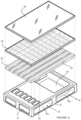
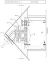
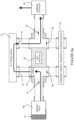
- a PVT apparatus 10 includes a body 12 having a hollow interior 14 providing chambers/ducts 16a, 18a associated with respective air inflow/inlet 16 and air return 18 ports/channels.
- a number of openings 20 convey air through jets 22 to cool an underside of a solar PV panel 24. Spaces between arrays of the jets provide drains 26 for warmed air to flow away via the return channel.
- Figure 1b shows an assembled PVT panel 10.
- additional glazing 30 can be provided over the PV panel.
- the spacing between the arrays of jets provides drains 26 for outflow of warm air, which can flow to the return channel 18 via an opening 32.
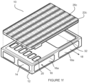
- Figure 1d shows an arrangement of drains 26a incorporated into a panel 22a incorporating arrays of the jets.
- the panel 22a includes an air interface portion 34 to connect to the inlet openings 20 to the panel of jets.
- Figure 1e shows an alternative version of the embodiment of a PVT panel of Figure 1d with larger 'spoon' drains 26b between arrays of the jets.
- Figure 1f shows a further alternative embodiment of the PVT panel of Figure 1d or Figure 1e with larger 'spoon' drains 26c between arrays of the jets.
- FIG. 1 An application of a preferred embodiment of a PVT apparatus 10 is shown mounted to a roof 36 of a building 38 in Figure 2a .
- Figure 2b shows a typical arrangement of a system embodying one or more forms of a PVT panel 10 of the present invention in a common domestic roof 36 application on a building 38. Excess heat can be vented to atmosphere via an exhaust 40.
- An inflow fan 42 and a return control valve 44 control cycling of cooling/heating into the room(s) 46 of the building.
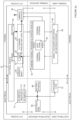
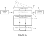
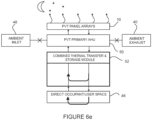
- Figure 3a shows a block diagram representing a complete integrated thermal and electrical system for a typical installation.
- the block diagram separately presents these for both electrical and thermal functions.
- the block diagram illustrates the functional relationship between the PVT system; the conversion, transfer and storage systems; and the end user systems.
- Figure 3a further represents the open loop mode with air being drawn in from ambient by the air handling unit to then be driven through the PVT panel and then returned to ambient via the exhaust.
- Figure 3b shows a similar block diagram as Figure 3a and further representing the closed loop mode with air being drawn in from the user space by the air handling unit then be driven through the PVT panel and then returned via the optional thermal transfer and storage module back to the user space.
- closed loop mode there is no net air volume transfer between the user space and ambient.
- Electrical supply can come from or to an electrical grid 66.
- the PVT system can supply electricity to battery/capacitor storage 68 and/or to a consumer load 70.
- DC electrical supply 72 from the PVT panels 10 can go through an inverter 74 and AC switching 76 to supply the grid 66 and/or the storage 68
- Figure 4 illustrates the air flow pathways for an open loop arrangement configured for the PVT cooling mode with occupant air -conditioning (AC) closed loop cooling mode during day time according to at least one further embodiment of the present invention.
- AC occupant air -conditioning
- the fan pushes the air into the inlet 16 of the PVT panel(s) 10 via the primary air handling unit (AHU) 50.
- AHU primary air handling unit
- a combined thermal transfer and storage unit 52 determines whether air from the PVT panel(s) is diverted to the interior of the building - depending on whether the air is warm or cool and whether the building needs heating or cooling.
- a heat pump 54 associated with a heat exchanger 56 can also or instead be used for heating/cooling.
- UV sanitation lights 58 can be provided to sanitise the air/moisture conveyed through the system.
- Air can be supplied 60 to/from the heat exchanger.
- Filters 64 remove particulates from the air.
- a PVT to heating, ventilation, and air conditioning (HVAC) interface module 62 can be provided.
- HVAC heating, ventilation, and air conditioning
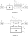
- Figure 5b shows an example of daytime PVT flow options.
- Figure 5c shows an occupant heat mode whilst
- Figure 5d shows a thermal storage mass (in the combined storage and heating module 52) heating mode
- Figure 5e shows an example of conducting both thermal mass storage and closed loop occupant heating.
- FIG. 6a A night time/evening arrangement is shown in Figure 6a .
- the PVT panels 10 can radiate heat, which can be removed from within the building and cooler air pumped into the rooms 46.
- Figure 6b shows a diagrammatic arrangement of cooling processes employed during evening/night time.
- Figures 6c and 6d show respective occupant cooling mode and thermal mass cooling mode applications.
- Figure 6e shows an example of combined cooling for the thermal mass and the occupants.
- One or more forms of the present invention employs a jet arrangement that delivers equal cooling potential through a series of cell air plenum's to each individual solar cell. This ensures an equivalent mean cell temperature across the entire panel and PV panel string.
- the heat transfer apparatus can employ a process called jet impingement which enables very high heat transfer rates to be achieved in comparison to other heat transfer processes (such as natural and force convention or radiative effects). This allows for compact packaging to be achieved with the potential for the cell air distribution plenums to be completely housed within the existing PV panel envelope. See, for example, Figure 1c showing a plenum arrangement.
- jet impingement cooling e.g. when coupled with the proposed arrangement of the jets on the cell air plenums and the adjacent drains created between each cell air plenum
- the air flow can be controlled across the entire flow regime.
- Achieving stable air flow ensures stable and efficient heat transfer across operating regimes, such as from low flow high grade heating process conditions through to high volume air flow cooling process enabling PV power capacity boosting.
- a supply duct 16a provides inlet air from the inlet 16 to an inlet port 110 suppling a cell air plenum 112 of the PV cell 10a.
- the PV cell is sealed to the body 12 by a seal 114. Return air from the PV cell air plenum flows into the return duct 18a and can then flow from the return outlet 18 to be utilised.
- Figure 11c shows a longitudinal cross section of a PVT apparatus according to an embodiment of the present invention. Air flows from the PV cell air plenum via jets/nozzles 116, absorbs heat radiating form the underside of the PV panel 10a, and returns via at leats one drain 118 to the return duct 18a.
- a jet/nozzle 116 can be provided by one or more profiled orifices/holes (x), such as shown in Figure 12d or as a slot (x) as shown in Figure 12b .
- a diameter "d" of each jet/nozzle orifice/holes(or width of a jet slot) that can be applied ranges between 0.5 to 5.0mm in increments of 0.5mm.
- a preferred orifice/hole diameter or slot width is 2.5mm.
- a cross-section of the jet/nozzle 116 can be can be expressed in several ways; extended straight wall ( Figure 13 (a) ); parallel squared edge profile ( Figure 13 (b) ); convex profile ( Figure 13 (c) ); concave profile ( Figure 13 (d) ); long radius nozzle-square end exit( Figure 13 €); long radius nozzle - pencil end ( Figure 13 (f) ); long radius nozzle - expansion end ( Figure 13 (g) ); long radius nozzle - mitred end ( Figure 13 (h) ).
- Reference to a jet also encompasses a nozzle and other orifices/openings for high velocity airflow.
- a preferred embodiment of the jet is the application of the long radius nozzle together with a pencil end.
- Such a cross-section provides for a low friction head loss factor, which reduces the fan power. It also provides for a method to reduce the distance between the jet outlet and the impinging PV cell, whilst providing a larger void for the spent jet fluid to discharge into and drain away through.
- Another advantage is that it reduces the entrainment of spent fluid into the jet, resulting in fewer disturbances to the jet structure and improved heat transfer performance.
- Height of the jet is defined as “h” for a flush mounted jet.
- the height of a jet type that is protruding away from the surface is defined as “H” and the route of the jet is defined as “h”, such as illustrated in Figure 13h .
- the height of the jet "h” is a variable parameter that is dependent on the application. It is a consideration of manufacturability, performance and restriction associated with the available space underneath the panel.
- the preferred jet height for is 10mm, with a preferred height range of 5 - 25mm.
- the height of a protruding jet "H” can be expressed as a proportion of "h".
- the preferred proportion for this application is 50% to minimise spent fluid entrainment into the jet, with a preferred range of 20 to 80%.
- the jet arrangement pattern is based upon generally achieving a consistent repeatable pattern for each PV cell along a PV panel string, with slight modification only being required to be applied in areas such as panel edges, PV panel string ends and obstructions such as PV junction boxes.
- the jet arrangement pattern is preferably configurable using combinations of holes and slots of differing diameters and spacing.
- the jet arrangement pattern will generally conform to a pattern that can be mirrored about the centreline axis of the PV panel string and will have a series of jets positioned collinearly with this centreline.
- the purpose of this arrangement is to divide the flow across the PV cells in half and to initiate the flow regime tangentially out from the centreline to the edge drains to enhance heat transfer and minimise the input power required.
- the additional jets are spaced tangentially from the centreline at a distance "x" and axially along the string centreline "y".
- the dimensions "x” and “y” are commonly referenced to a ratio of the jet diameter to enable performance comparison to be undertaken.
- a preferred ratio is 10, with a possible applicable range of 5 to 25.
- Figures 14a to 14i illustrate examples of the preferred options of this embodiment, with Figure 14e showing a particularly preferred embodiment.
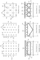
- Figure 14a-a shows a schematic partial plan view section of the upper surface of a cell air plenum 112 that represents an arrangement incorporating a uniform grid pattern distribution of the jets 116 with drains 118 running down only two sides according to an embodiment of the present invention.
- Figure 14a-b shows a schematic of the cross sectional view of Figure 14 a-a showing the general profile of a square air cell plenum 112 and the localised air flow according to an embodiment of the present invention.
- Figure 14b-a shows a schematic partial plan view section of the upper surface of a cell air plenum 112 that represents the arrangement incorporating an offset grid pattern distribution of the jets 116 with drains118 running down only two sides according to an embodiment of the present invention.
- Figure 14b-b shows a schematic of the cross sectional view of figure 14 b-a showing the general profile of a triangular air cell plenum 112 and the localised air flow from jets 116 according to an embodiment of the present invention.
- Figure 14c-a shows a schematic of a partial plan view section of the upper surface of a cell air plenum 112 that represents an arrangement incorporating a grid pattern distribution of the jets 116 and internal cell air plenum drains 118 according to an embodiment of the present invention.
- Figure 14c-b shows a schematic of the cross sectional view of figure 14 c-a showing the general profile of a square air cell plenum 112 with the inclusion of additional drains 118 through the body of the cell air plenum 112 and the resultant localised air flow according to an embodiment of the present invention.
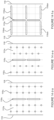
- Figure 14d-a shows a schematic of a partial plan view section of the upper surface 112a of a cell air plenum 112 that represents the arrangement incorporating a series of slotted jets/nozzles 116s along the air cell plenum axial centreline and the incorporation of uniform grid pattern distribution of orifice jets 116o either side of the slotted jets/nozzles 116 and drains 118 running down each edge according to an embodiment of the present invention.
- Figure 14e-a shows a schematic of a partial plan view section of the upper surface 112a of a cell air plenum 112 that represents the arrangement incorporating a series of slotted jets 116s along the air cell plenum axial centreline and the incorporation of offset grid pattern distribution of orifice jets 116o either side of the slotted jets 116s and drains 118 running down each edge according to an embodiment of the present invention.
- Figure 14f-a shows a schematic of a partial plan view section of the upper surface 112a of a cell air plenum 112 that represents the arrangement incorporating a series of slotted jets 116s, with one set aligned with the air cell plenum axial centreline and the other slots 116sn normal to the centreline and extending towards the edge towards the drains according to an embodiment of the present invention.
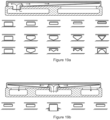
- Figure 14g shows a schematic of a partial plan view section of the upper surface 112a of a cell air plenum 112 represented in Fig 1d that illustrates an arrangement incorporating a uniform grid pattern distribution of the jets with segmented drains running down only two sides. Further included are schematics of the cross sectional views B-B ( Figure 14gB-B ) and C-C ( Figure 14gC-C ) showing the general profile of an air cell plenum 112 and the localised slotted drains 118s for spent air flow according to an embodiment of the present invention.
- Figure 14h shows a schematic of a partial plan view section of the upper surface of a cell air plenum 112 represented in Fig 1e that illustrates an arrangement incorporating a uniform grid pattern distribution of the jets 116 with segmented drains 118s running down only two sides. Further included schematics of the cross sectional views B-B ( Figure 14hB-B ) and C-C ( Figure 14hC-C ) showing the general profile of an air cell plenum 112 and the localised drains 118s for spent air flow according to an embodiment of the present invention.
- Figure 14i shows a schematic of a partial plan view section of the upper surface of a cell air plenum represented in Fig 1f that illustrates an arrangement incorporating a uniform grid pattern distribution of the jets with spoon drains incorporated between the jets normal to the PV cell centreline.
- the spoon drains cross-sectional area increases as it progresses from the PV cell centreline to the drain located on the PV cell perimeter. Drains run in an array down only two sides.
- Spent jet fluid drains and their placement are valuable features of one or more embodiments of the present invention.
- the drains determine how the fluid is removed from jet discharge and conveyed towards the outlet port.
- the drains are generally achieved as a result of the spaces that are developed between adjacent cell air plenums and the PV panel edge.
- Drain width "d" ( Figure 11b ) when multiplied with cell air plenum length "L” can be expressed as a ratio of the cell air plenums cross sectional area immediately after the inlet which is normal to the PV panel surface.
- a preferred ratio is at least 1, with a possible range of 0.5 to 5.
- An alternative arrangement of one or more embodiments of the present invention includes the adoption of a single air cell plenum for the complete PV panel (instead of a PV string). Such an arrangement can include the provision of drains through the plenum. An example of this is illustrated in Figure 1d .
- the total sum of drain area "D" can be expressed as a ratio of the cell air plenum's cross sectional area immediately after the inlet which is normal to the PV panel surface.
- the invention's HTM flow path geometry aims to maintain near constant air velocity from inlet to outlet except in the actual jet.
- the purpose of this is to keep losses to a minimum and to achieve common pressure profile in any single planar cross-section that is perpendicular to the PV cell surface and perpendicular to the longitudinal axis of the air plenum. This is the primary reason for the tapering down of the cell air plenum from its inlet. See for example Figure 11d.
- One or more forms of the present invention realises that the heat transfer capacity of the jet can be further enhanced with the adoption of surface treatments on the PV cell 10 backing sheet and/or physical attachments. This feature is not limited to the application of PV heat transfer. For example, see Figure 15a to Figure 15e .
- the surface treatments referred to include impression(s) or ridges/ roughness introduced into the external plastic layer of the PV encapsulation process most widely adopted by industry (aka Du Pont 'Tedlar ® ' durable, weather-resistant pv backsheet for photovoltaic PV solar panels/modules).
- impressions, ridges and/or roughness can be further arranged to mirror and align with the jet 116 pattern.
- the ridgelines could radiate out linearly from the jet centreline/plane ( Figure 15a ) or radiate out curvilinear to form a spiral pattern ( Figure 15b ).
- the physical attachments referred to can be employed in three general areas of the jet 116 path; immediately underneath the jet axis, along the jet's surface trajectory and at the boundary between two interposing jets (See Figure 15c and Figure 15d ).
- the attachments located underneath the jet can be profiled to provide infinite control to the direction and volume of flow upon impingement with it. This can range from concentric flow (nipple like profile) through to a complete jet change of direction (bucket like profile).
- Attachments that are fixed along the jets surface trajectory are employed to induce turbulence in the jet and breakdown the jet boundary layer to replenish it with fresh working fluid.
- the attachments located at the jet boundary layers introduce additional surface area to increase thermal conduction and also initiate the direction of the spent fluid away from the heat transfer surface.
- Additional physical attachments such as deflector ridges/projections 128, can be employed directly above the drains 118 to redirect the spent air into the drain 118 to minimise turbulence, such as shown for example in Figure 15e .
- a deflector 124 can be provided directly above the exit to the jet/nozzle 116. Airflow so directed can be influenced by one or more turbulators 126 introducing turbulence into the airflow. A deflector ridge 120 can redirect the airflow towards the drain 118
- the cell air plenums 112 can be manufactured in large quantities using a plastic blow moulding technique commonly employed in forming intake air plenums on engines and within the air conditioning circuit for the automotive industry. Additives can be included in the plastic formulation to enable polymer cross-linking to increase thermal and structural rigidity and increase resistance to fire and UV degradation.
- the manufacture of the cell air plenums is not limited to this technique, and other techniques, such as injection moulding, vacuum moulding and fabrication, are envisaged.
- the cell air plenums for each panel's internal string are in principal the same. Modifications to the mould can be easily implemented to facilitate the customisation of a plenum to accommodate the protruding panel junction box and additional edge jets for extending air coverage when accommodating panels with broad panel frame flanges.
- Additional jets 116 can be included around the junction box to increase cooling if required.
- PV panel designs envisaged within the present invention may have the junction box omitted from the panel back altogether and include smaller panel flanges reducing the need to customise the plenums.
- one or more condensate flow channels 130 may be provided within the PV panel 10. Such condensate flow channels 130 may have a pattern generated from a slightly inclined panel when operating in the night radiative cooling mode according to an embodiment of the present invention.
- the condensate flow channels 130 can be along the underside of the PV panel 10 towards the condensate collection drain 132 via the condensate collection channel 130 according to one or more embodiments of the present invention.
- Figure 16c shows a detailed cross section view B-B schematic of Figure 16a (Figure 16b being a cross section A-A of Figure 16a ) illustrating the fixture of the condensate channel to the underside of the PV panel and how the flow is directed into the channel and then delivered to the collection drains according to an embodiment of the present invention.
- the cell air plenums are generally preferred to be arranged in line with the PV string orientated to the inclined plane with the inlet vent/s located on the lower inclined end. This facilitates the evacuation of the spent air towards the panel outlet vents through the buoyancy effect of the air which incrementally improves the systems performance.
- the cell air plenum can be further insulated with insulation 134 below the cell plenum to increase performance of the system by reducing the heat gain of the spent air as it flows along the back of the air cell plenum towards the vent maintaining the constant air temperature to the cells, such as shown in Figures 18a to 18d .
- Additional insulation 136 can be applied to the upper surface to further reduce heat ingress into the plenum, such as shown in Figure 18c
- the cell air plenums can further enhance the recovery of radiative energy with the inclusion of an insulated selective infrared radiation absorber material 138 onto the jet 116 face 112a of the plenum. This is employed to capture the radiated energy and prevent it from heating the intake air before it is expelled into the jet. The spent jet air then cools the absorber plate before it is expelled through the drains and into the outlet vent, such as shown in Figure 18d .
- the height (depth) of one or more cell air plenum can taper from the inlet to the outlet port to provide for the increasing volume required for the flow rate in the spent fluid stream as it moves towards the outlet port. This approach ensures that the flow rate of the spent air is stable across the length of the panel.
- a bottom panel enclosure sheet 140 can be provided below the PV panel and plenums.
- An alternative embodiment of this approach is to maintain the same cross-sectional area from any comparative section but to include a vee shape in the underside profile instead of a planer one which will provide additional structural rigidity and also enhance the segregation of spent fluid streams and reducing cross flow potential. This is more critical when the spent fluid is constrained only to the depth of the PV panel before it leaves the outlet port, which can be the case in some optional embodiment/arrangements. See for example, Figure 14b-b and including Figure 19a and Figure 19a .
- the PV panels preferred mounting arrangement utilises the described mounting cassette, but is to be understood to not be limited to such.
- the general purpose of the standard mounting cassette is to provide a structural framework to secure the PV panel to the roof. It preferably also provides the internal duct work to supply both the panel's intakes and outlet vents and provides a mounting mechanism to physically secure the cell air plenums and seal the joint between the cell air plenum inlet port and the internal ductwork.
- the mounting cassette can provide the sealing surface to enclose the PV panel back face to prevent air leakage to the outside.
- Internal ducting in the mounting cassette can be configured to be interconnected to the adjacent panels, act as a duct terminator and/or act as a roof penetration access point to convey the air between the PVT system and building.
- the ducting can further insulated 142 to increase thermal performance. See for example, Figure 20a and Figure 20b series of cross sectional views.
- the mounting cassette can be manufactured in large industrialised quantities at a low cost using either a blow moulding or injection moulding process. This enables complex shapes and surfaces to be realised in the one process. Inclusions to the mould will facilitate a wide number of installation opportunities from roof fixtures, to cantilevered vertical structures through to free standing structures. Mould inclusions can readily accommodate a wide range of air duct combinations.
- the same form and function of the mounting cassette could also be achieved using more traditional forms of manufacture using materials such as sheet metal, plastics and weather resistant timbers and ply.
- Additional mounting cassette features that can be included in the mounting cassette frame are; roof mounting features for existing roofs to secure PVT systems directly to membranes 144 ( Figure 21a ), corrugated 146 ( Figure 21b ) and trim-deck 148 ( Figure 21c ) like profiles and indirectly to slate and tile options.
- Additional cavities can be included to facilitate the installation of the cassette over pre-existing solar mounting frames.
- the battens are usually installed at 900mm spacing - see Figures 22a through to Figures 22c .
- the cassette can have a body 12 centrally mounted, as shown in Figure 22a or may have an (left) offset towards the intake 16 or an (right) offset towards the return 18, as shown by way of example in Figures 22b and 22c respectively.
- the mounting cassette can also be configured so that it can be cantilevered and supported from a single end.
- the cantilevering arrangement can be pitched at a fixed angle such that the PVT panel is inclined up, flat or down from the mounting point, as referenced in Figures 23a through to Figures 23c .
- a further arrangement of this concept is to enable the PVT panel inclination angle to be set within a full range of 180 degrees with the extents starting from a full vertical up position to a fully vertical down position, as shown in figure 24 .
- a mounting frame 150 can be attached to a support 152, such as a wall.
- At least one functional duct connection to the mounting arrangement can be provided which can be either intake or exhaust.
- an air filter 154 can be fitted to the intake. Reference is made to Figure 24 . This arrangement can then be mounted directly to a wall or equivalent vertical structure.
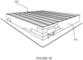
- Figure 25 shows an exterior view of a building 156 including an awning 158 alongside one side thereof including multiple PVT panels/systems embodying the present invention.
- the mounting cassette can be configured in various ways to facilitate mounting and connection of two adjacent panels or customised mounting structures utilising connectors 160, 162, or a mounting bracket 164 such as illustrated in Figure 26a through to Figure 26c .
- a further variation of this aforementioned arrangement is to have cantilevered PVT panels secured to a common spine with a PVT panel/s mounted such that they are mirrored around the spine.
- the spine provides both structural and ducting support for air services, as indicated in Figures 27 a through to Figure 27d .
- the mounting cassette can be configured to be integrated directly into the roof structure 166, such as shown in Figure 27a , which can include incorporated water proofing features and drainage.
- the mounting cassette can also be configured to be a completely freestanding flat, see for example Figure 27a , or pitched roof as in Figure 27b . This may be more desirable on commercial buildings where space is usually required for or already occupied with other services.
- Additional service features that can be incorporated in the mounting cassette include a small access walkway 168 and/or cable tray 170 to facilitate high density arrays by providing individual panel access for installation, maintenance and future servicing, as shown in Figure 28a .
- Cabling duct can also be included for instrumentation or power requirements. Guttering 172 can be incorporated for water collection purposes. See for example Figure28b )
- Thermal Enhancement through Glazing An option to reduce the panels conductive and convective loses through the upper glazed surface 174 (and further enhance the thermal energy capture of the PVT system) of one or more embodiments of the present invention is to apply a double glazing solution.
- An additional glazing element 176 can be applied to the top face of an existing PV panel. This is an option that can be retrofitted upon installation of the PVT system where thermal demand is not being met by the standard single glazed PV panel. See for example Figure 1c . This can be beneficial in colder climates with limited solar exposure.
- the height of the double glazing standoff is significant factor. Limiting its height above the existing glass and the extents of it supporting frame ensures that shading caused by these elements is kept to an absolute minimum so as not to impact the electricity production. See for example Figure 29a .
- a further alternative embodiment to the above double glazing option is to manufacture a new PV panel.
- the glazed element of the PV string can afford to be much thinner as it is no longer exposed to the elements.
- the glazed PV string can be fixed directly to the glass using a durable adhesive and with the introduction of standoff elements to provide an appropriate air gap between the glazed PV string and the upper glass surface. See for example Figure 29c .
- An alternative fixing arrangement is to fix the glazed PV string to the cell air plenum.
- the cell air plenum can be modified to include additional fixing supports for the glazed PV string as well as integrated stand offs 180 to achieve a consistent air gap between the glazed surfaces. See for example Figure 29d .
- supplementary jet cooling 182 directed between the glazed air gap 184, as shown in Figure 29e and Figure 29f .
- One or more forms of the present invention facilitates multiple possible uses for the produced thermal energy. Such energy can be used to heat or preheat space within an occupied built environment (home /commercial), hot water services, hydronic heating systems, heat pump evaporators and thermal masses but not limited to these uses. Additional commercial uses can include drying agricultural, wood or industrial product, heating animal houses, heating greenhouses and heating district hot water systems to name a few.
- Figure 9 illustrates this application in a single dwelling.
- the heating capacity is wholly dependent on three key factors, two of these are fixed and are outside the ability of the controller to change. These are the surface area of PVT installed and the solar insolation available.
- the third factor is the volume of air applied to the system.
- the air's thermal capacity W/kgK is considered to be constant for the typical operating temperature range. As a result the outlet temperature for a given set of conditions is entirely dependant on flow rate.
- Figure 10a illustrates the thermal mechanisms associated with a fixed set of conditions for a theoretical heat exchanger with 100% efficiency and compares this to a high efficiency heater exchanger as presented in this invention and a lower performing heat exchanger.
- Figure 10b shows a chart of typical thermal performance of a PVT system embodying the present invention by way of comparison with the chart showing known PVT systems.
- Figure 10c shows a comparison chart of typical solar collect performance of at least one embodiment of the present invention compared to a range of known solar collectors.
- one or more forms of the present invention incorporates options to introduce ambient air to the PVT system at a temperature lower than the PV cell/panel surface temperature condition by employing a range of cooling techniques either individually or in combination.
- Temperature conditioning of ambient air drawn in via the ambient inlet 48 can be provided by an ambient (air) temperature conditioning system/device 60, as shown by way of example in Figure 7a .
- ambient air can be precooled by an evaporative cooler 62 fed with water, such as from a mains water supply 64.
- the water can be pumped via a pump 66 to sprays 68 to wet pads through which the ambient air is drawn to supply pre-cooled air to the PVT primary air handling unit (AHU) 50.
- AHU PVT primary air handling unit
- water supplied to the evaporative cooler may be pre-chilled via a chiller unit 70, which can help to extract additional heat form the incoming ambient air, further pre-cooling the air to the AHU.
- Evaporative cooling techniques can nominally reduce ambient temperature by 10 degrees C subject to the humidity levels of the air entering the cooler.
- a 10 degrees C reduction in panel temperature returns a nominal 5% gain in PV capacity when compared to simple ambient air cooling. Further cooling can be achieved in evaporative cooling if chilled water is circulated in through evaporative media, such as shown in Figure 7c .
- the thermal mass 72 can be in many forms including solid material (concrete/aggregate), liquid (water) and more recently phase change materials (ice, long chain hydrocarbons, salts), as indicated in Figure 7d and Figure 7e .
- the chilled thermal mass can be associated with the combined thermal transfer and storage module 52.
- the chilled thermal mass 72 can be provided between the ambient air inlet and the PVT primary AHU.
- one or more forms of the present invention provides the unique feature of being suited to radiative night cooling applications with no or little modification to the daytime PVT mode.
- Radiative night cooling is an effective means of cooling objects below ambient air temperature. To explain this phenomenon by example, it is what enables frost to form on black roofs even with ambient minimum temperature well above zero degrees.
- Intake air can be drawn from outside, inside a building/facility or from a thermal storage mass depending on application. This air is filtered and then driven through the PVT circuit.
- a combination of radiative night cooling, with sufficient internal thermal mass and adequate perimeter insulation, can be provided to prevent the need for auxiliary forms of cooling even in the hottest climates.
- One or more embodiments of the present invention provides the benefits of night cooling whilst doing so in an airtight environment when used in a closed loop mode. This reduces the occupant's exposure to dust, pollen, security concerns, outside noise and vagaries of the wind disturbance which can all impact on a healthy and safe living space together.
- a radiative night cooling mode can be used to recharge the cooling potential of thermal storage systems which have been referred to as a technique for cooling the PVT during daytime operations, as indicated in Figure 7d and Figure 7e .
- one or more embodiments of the present invention can generate condensation in varying quantities subject to the air intake's humidity and night sky temperature.
- the condensation collection points can be incorporated into the base of the HTMM for removal from the panel using either gravity or assisted means.
- Figure 8a shows an example of an open loop mode of operation of the system.
- Ambient air is drawn through a filter 74 at the ambient air inlet 48.
- An inlet valve 76 is open to allow the air to pass, via the fan 42, to the PVT panel array and to exit via an open outlet valve 78 to the ambient exhaust 40.
- inlet valve 82 and outlet valve 80 associated with the combined thermal transfer and storage device are maintained closed.
- FIG. 8b An alternative mode of operation is shown by way of example in Figure 8b , wherein the inlet valve 76 is closed to prevent ambient air being drawn in from the external atmosphere.
- An outlet valve 80 of the combined thermal transfer and storage module draws cool air from the building/room, passes the air through the PVT panels for heating the air, and feeds the warmed air back into the room via inlet valve 82.
- the outlet ambient air valve 78 is closed.
- the extended surface referred to in (see Figure 15e ) can be modified to provide a method to entrap the moisture and (then through capillary action and channelling) drain the condensation to one end of the panel to a collection manifold.
- Filtering / Sanitisation one or more forms of the present invention incorporates filtering of the air before it enters the PVT circuit in either open or closed loop operation to maintain the long term performance of the system whilst maintaining good air quality.
- Additional sanitisation methods such as UVC light sources can further sustain long term air quality and performance by preventing the build-up of biological elements on filters and heat exchanger coils, as indicated in Figure 4 .
- one or more forms of the present invention can include a duct that connects the PVT outlet duct to atmosphere. The flow through this duct can be controlled through the engagement of at least one fan and/or at least one valve.
- the speed of the fan(s) and the actuation of the valve(s) can be controlled either manually or remotely, such as utilising an integrated control system.
- the primary purpose of the heat exhaust outlet is to expel the excess hot air generated which is greater than the systems thermal demand. It is generally located downstream of any additional energy transfer units such hot water heating as an example.
- the thermal heat exhaust system can also incorporate an air/air heat exchanger that can be engaged to ensure adequate volumes of replenished air from outside are introduced into the house. This feature enables the heat from any exhausted air to be recovered by the replenished outside air drawn through the intake. This requirement is applicable when the system is operated in closed loop mode, as indicated in Figure 4 .
- Main Air Ducting one or more forms of the present invention can incorporate a number of features that enables many configurations of main ducting to be considered. The selected configuration will then determine the type of cell air plenum used. The ducting moulded into the mounting cassette will be open ended. Closure is achieved with a duct termination plate. The mounting arrangement/cassette underside will provide the option for main duct entries ports which need to be cut out for use.
- the invention considers the preferred arrangement of main ducting to be axially along a length of a PVT string that is orientated with the PVT panel aligned with their long axis.
- a preferred orientation of the main ducting inlet and outlet are at opposing ends of the PVT string to passively facilitate balance flow across all PVT panels.
- the invention considers that the main inlet and outlet ducts are insulated inside the PVT apparatuses and as they extend beyond the apparatus.
- the invention considers that during a closed loop mode of operation the system's performance will benefit from reversing the location of the air draw and discharge points within a room/space when switching from heating and cooling modes.
- air is drawn from the upper extents of the room and the air discharged at the lower extents to prevent mixing.
- the air is drawn from the lower extents of the room and the air discharged at the upper with adequate velocity to ensure thermal comfort to the occupants. See for example Figure 5a .
- Air Handling Unit/s AHU: One or more forms of the present invention encompasses methods and arrangements for conveying the air through the PVT circuit/s and auxiliary services.
- One or more embodiments include the use of electrically driven axial, centrifugal and mixed flow fans.
- Operation and maximum flow control the electric fan motors can be deployed using EC or equivalent variable speed control techniques.
- Flow control setting can be established by the controller.
- Manual fan control can be employed.
- a single fan can be located between the inlet filter and the inlet duct/s of the PVT system (which may contain one or more PV string elements), such as shown in figure 30d .
- a primary fan used in conjunction with secondary fan/s configured in a parallel arrangement can be employed to address any balancing issues, as shown in Figure 30e through to Figure 30h .
- One or more auxiliary fans can be employed for delivering air to other services such as the outside air exchange module; thermal storage modules; hydronic heat exchange modules, hot water heat exchange module, heat pump condenser/evaporator heat exchange module and internal air distribution, as shown in Figure 9 .
- Warmed air from the PVT panel array 10 can be fed into the combined thermal transfer and storage module 52. As shown by way of example in Figure 9 , air can be diverted via closed valve 86 and open valve 84 to the combined thermal transfer and storage module 52.
- a heat transfer inlet valve 88 can be opened to allow the air to be directed to thermal transfer unit 90 incorporating thermal transfer (heat exchange or HEX) for hot water (hot water storage 100), hydronics (hydronic header 102), a heat pump (for heating, ventilation and air-conditioning, HVAC 104), a heat pump for heat exchange with the hot water system or hydronics system/header for use in heating, ventilation and air-conditioning HVAC.
- thermal transfer heat exchange or HEX
- HVAC heating, ventilation and air-conditioning
- An outlet valve 90 allows return air to flow back to the PVT panel array (via open valve 80 and the fan 42). Valves 92, 94, to the cold thermal mass 96 and hot thermal mass 98 are maintained closed.
- One or more forms of the present invention incorporate one or both of two primary modes; closed loop and open loop.
- Closed loop corresponds to no net transfer between the complete PVT circuit including any building envelope/space forming part of that circuit and the outside environment.
- the open loop system preferably involves a differential in flow rate between any two or more elements of the circuit.
- the inlet air can be drawn from outside, forced through the PVT circuit and spent air expelled back outside through the exhaust.
- a secondary mode of operation relates to either daytime generation (heat and electricity) or night-time cooling.
- a third mode of operation relates to maximising the combined energy yield of the PV and Solar system at any point in time or daily. It establishes the optimal air flow rate through the PVT and determines where best to source the intake air.
- a fourth mode of operation relates to any other operational state that is not the third mode.
- This mode is a response to one or more of market forces, internal demand or consumer preferences.
- the PVT system maybe set to deliver high-grade heat during winter and when electricity prices are low.
- the system in this mode has reduced air flow to allow the PV cells to retain more heat.
- control system market response algorithm defers any internal loads and then switches the PVT system duty from space heating to panel cooling. It does this by switching into open loop mode and draws in cold outside air and expels the spent air through the exhaust (assuming the outlet temperature is colder than the room set point temperature).
- the resultant effect is a reduction in panel temperature of 40 degrees C and a 20% boost in PV production. In this case it is assumed that the value of the lost heating is less than the revenue attained from the electricity sale.
- a domestic hot water system may call for additional heat due to a large demand placed upon it.
- the system operating in mode 3 delivers high volume lower grade space heating.
- the hot water demand switches the system to mode 4 and the control system reduces the air flow.
- the PV cells subsequently heat up to a temperature that delivers the required conditions to heat the water.
- Control System and Instrumentation Operation of one or more forms of the present invention can be by the use of a control system, but is not limited to this.
- the control system preferably centralises all the physical inputs from the PVT system and other external systems that have a determining effect on how the system operates and performs. It then references these conditions against an operating mode algorithm and sends the appropriate updated commands to control fan speed and valve actuation.
- Physical inputs from the PVT system could include central or micro inverter data (DC power, DC volts, DC amps, AC power, AC volts, AC amps frequency), air flow measurements (delivered air, outside air transfer module), air pressure sensors (across the fan, across the filter/s, across PVT panel inlet and outlets and across heat exchanger modules), air temperature probes (ambient, ambient air intake, room/space air intake, exhaust air, PVT panel surface and air outlets, air inlet and outlets to various heat exchange modules, fluid inlet and outlet temperatures associated with the respective various heat exchanger modules, room/space), ducting valve actuation status, fan operational data (speed, power, current, volts).
- central or micro inverter data DC power, DC volts, DC amps, AC power, AC volts, AC amps frequency
- air flow measurements live air, outside air transfer module
- air pressure sensors as the fan, across the filter/s, across PVT panel inlet and outlets and across heat exchanger modules
- air temperature probes ambient, ambient air
- Tables 1 and 2 below show lists of system inputs/outputs (I/Os).
- Tables 1 and 2 show the associated input and output conditions that can be monitored or changed to effect adequate control of the PVT system according to at least one embodiment of the present invention.
- a PVT system 200 can include a single PV panel, such as for providing the very basic of needs of an impoverished community - see Figures 35a through to Figure 35c .
- the PVT system can include one or more PVT strings, with PVT panels numbering between 6 and 16 plus for an existing single dwelling roof top application, as indicated in Figure 2a .
- the PVT system 200 can be installed across the entire existing roof or better still become the roof in new building constructions 202 (see for example Figures 36 ).
- PVT systems embodying the present invention can be cantilevered off walls or even shop fronts, increasing the available area to extract solar energy that was previously unrealised. PVT systems embodying the present invention can also be installed in large scale solar systems adjacent to farms of industrial facilities that have a need for thermal energy.
Landscapes
- Engineering & Computer Science (AREA)
- Physics & Mathematics (AREA)
- Thermal Sciences (AREA)
- Mechanical Engineering (AREA)
- General Engineering & Computer Science (AREA)
- Sustainable Development (AREA)
- Life Sciences & Earth Sciences (AREA)
- Sustainable Energy (AREA)
- Chemical & Material Sciences (AREA)
- Combustion & Propulsion (AREA)
- Architecture (AREA)
- Civil Engineering (AREA)
- Structural Engineering (AREA)
- Photovoltaic Devices (AREA)
Applications Claiming Priority (2)
| Application Number | Priority Date | Filing Date | Title |
|---|---|---|---|
| AU2017904802A AU2017904802A0 (en) | 2017-11-28 | Improvements to solar panels and harvesting of solar derived energy | |
| PCT/AU2018/051267 WO2019104380A1 (en) | 2017-11-28 | 2018-11-28 | Improvements to solar panels and harvesting of solar derived energy |
Publications (4)
| Publication Number | Publication Date |
|---|---|
| EP3718147A1 EP3718147A1 (en) | 2020-10-07 |
| EP3718147A4 EP3718147A4 (en) | 2021-09-08 |
| EP3718147C0 EP3718147C0 (en) | 2025-06-04 |
| EP3718147B1 true EP3718147B1 (en) | 2025-06-04 |
Family
ID=66664160
Family Applications (1)
| Application Number | Title | Priority Date | Filing Date |
|---|---|---|---|
| EP18883857.7A Active EP3718147B1 (en) | 2017-11-28 | 2018-11-28 | Improvements to solar panels and harvesting of solar derived energy |
Country Status (9)
| Country | Link |
|---|---|
| US (1) | US11888444B2 (pl) |
| EP (1) | EP3718147B1 (pl) |
| CN (1) | CN111656537B (pl) |
| AU (2) | AU2018377851A1 (pl) |
| CA (1) | CA3083535A1 (pl) |
| ES (1) | ES3038118T3 (pl) |
| NZ (1) | NZ765452A (pl) |
| PL (1) | PL3718147T3 (pl) |
| WO (1) | WO2019104380A1 (pl) |
Families Citing this family (20)
| Publication number | Priority date | Publication date | Assignee | Title |
|---|---|---|---|---|
| SE1950112A1 (en) * | 2019-01-31 | 2020-08-01 | Samster Ab | Hybrid power and heat generating device |
| US12405012B2 (en) * | 2019-07-15 | 2025-09-02 | Lasting Image Laser Etching Company | Apparatus and method for solar heat collection |
| US11613891B2 (en) * | 2020-08-25 | 2023-03-28 | Paul A. Inglese | Fiber reinforced polymer building systems and methods |
| US11674312B2 (en) | 2020-08-25 | 2023-06-13 | Paul A. Inglese | Pultruded fiber reinforced polymer building systems and methods |
| DE102021104205A1 (de) * | 2021-02-23 | 2022-08-25 | Ebm-Papst St. Georgen Gmbh & Co. Kg | Vorrichtung zur Umwandlung von Sonnenlichtenergie in elektrische Energie und Wärme |
| FR3125328B3 (fr) * | 2021-07-15 | 2023-09-15 | Totalenergies Se | Système solaire |
| KR102616165B1 (ko) * | 2021-08-03 | 2023-12-21 | 한국건설기술연구원 | 공기의 충격젯을 이용한 태양광 발전효율 향상 장치 |
| US11821654B1 (en) * | 2021-10-26 | 2023-11-21 | Chad Schoppel | Attic hot air recirculation system |
| KR102715585B1 (ko) * | 2022-01-03 | 2024-10-11 | 한국그린에너지(주) | 스마트팜의 열에너지효율을 향상시키는 태양광 발전 구조물 |
| US20230296287A1 (en) * | 2022-03-21 | 2023-09-21 | United States Of America As Represented By The Secretary Of Agriculture | Modular floor cassette |
| US20230358414A1 (en) * | 2022-05-07 | 2023-11-09 | Cambridge Research and Technology L.L.C. | Grid Independent Heating System and Method for Buildings that uses Collector Accumulator and Transformer (CAT) |
| CN115198976B (zh) * | 2022-07-21 | 2024-08-20 | 温州市工业设计院有限公司 | 一种用于光伏一体化建筑的多级雨水收集系统 |
| US12445085B2 (en) | 2023-01-20 | 2025-10-14 | Som Iw Holdings, Llc | Solar autonomous roof assembly |
| CN116428737B (zh) * | 2023-02-22 | 2026-01-30 | 大连理工大学 | 基于重力供液的两循环pvt热泵热水系统 |
| CN116951599A (zh) * | 2023-06-13 | 2023-10-27 | 珠海格力电器股份有限公司 | 一种光伏空调系统及其控制装置、装置和存储介质 |
| FR3153100B1 (fr) * | 2023-09-14 | 2025-10-10 | Joel Gilbert | Toiture photovoltaïque et generatrice d'eau atmospherique |
| WO2025193925A1 (en) * | 2024-03-13 | 2025-09-18 | The Penn State Research Foundation | Simultaneous sub-ambient daytime radiative cooling and photovoltaic power generation from the same area |
| US20250314387A1 (en) * | 2024-04-08 | 2025-10-09 | Hollick Solar Systems Limited | Solar thermal energy collection and storage for heating buildings |
| WO2025262521A1 (en) | 2024-06-17 | 2025-12-26 | D.D. Innovation Srl | Hybrid energy production system |
| US12235044B1 (en) * | 2024-07-12 | 2025-02-25 | Guangdong Ocean University | Heat-collecting forage drying system with wind-solar complementary energy supply |
Citations (2)
| Publication number | Priority date | Publication date | Assignee | Title |
|---|---|---|---|---|
| FR2727790A1 (fr) * | 1994-12-02 | 1996-06-07 | Cythelia Sarl | Module solaire hybride photovoltaique et thermique fonctionnant en cogeneration de chaleur et d'energie electrique |
| WO2015103666A1 (en) * | 2014-01-07 | 2015-07-16 | Bluescope Steel Limited | Cladding sheet |
Family Cites Families (16)
| Publication number | Priority date | Publication date | Assignee | Title |
|---|---|---|---|---|
| US4201195A (en) * | 1978-10-25 | 1980-05-06 | Thermo Electron Corporation | Jet impingement solar collector |
| US5851309A (en) * | 1996-04-26 | 1998-12-22 | Kousa; Paavo | Directing and concentrating solar energy collectors |
| US20070028960A1 (en) | 2005-08-03 | 2007-02-08 | The University Of Sydney | Active cooling device |
| US20080223436A1 (en) * | 2007-03-15 | 2008-09-18 | Guardian Industries Corp. | Back reflector for use in photovoltaic device |
| US20090032098A1 (en) * | 2007-08-03 | 2009-02-05 | Guardian Industries Corp. | Photovoltaic device having multilayer antireflective layer supported by front substrate |
| CN102203521B (zh) * | 2009-01-18 | 2013-11-13 | 泰吉有限公司 | 太阳热能收集系统 |
| FR2967817B1 (fr) * | 2010-11-22 | 2013-08-16 | Solaire 2G | Panneau solaire hybride. |
| US9848509B2 (en) | 2011-06-27 | 2017-12-19 | Ebullient, Inc. | Heat sink module |
| GB2500706A (en) | 2012-03-30 | 2013-10-02 | Ibm | Concentrating solar photovoltaic-thermal hybrid systems |
| US20140166073A1 (en) * | 2012-12-14 | 2014-06-19 | Sunedison Llc | Methods and systems for increasing the yield of photovoltaic modules |
| US9263986B2 (en) * | 2014-01-03 | 2016-02-16 | Douglas Williams | Solar hybrid photovoltaic-thermal collector assembly |
| US20160120065A1 (en) | 2014-10-27 | 2016-04-28 | Ebullient, Llc | Manifold for a cooling system |
| CN107709890A (zh) | 2015-05-26 | 2018-02-16 | 太阳能焦耳知识产权控股有限公司 | 对加热、通风和空调系统的改进 |
| KR20170089750A (ko) | 2016-01-27 | 2017-08-04 | 한국에너지기술연구원 | 건물일체형 pvt모듈 및 시스템 |
| WO2018217398A1 (en) * | 2017-05-26 | 2018-11-29 | Johnson Controls Technology Company | Air handling unit and rooftop unit with predictive control |
| WO2019024061A1 (zh) * | 2017-08-03 | 2019-02-07 | 大连理工大学 | 一种可利用太阳辐射和天空冷辐射实现昼夜分时热电冷供应的 pvt 热泵系统 |
-
2018
- 2018-11-28 WO PCT/AU2018/051267 patent/WO2019104380A1/en not_active Ceased
- 2018-11-28 CA CA3083535A patent/CA3083535A1/en active Pending
- 2018-11-28 US US16/766,758 patent/US11888444B2/en active Active
- 2018-11-28 EP EP18883857.7A patent/EP3718147B1/en active Active
- 2018-11-28 PL PL18883857.7T patent/PL3718147T3/pl unknown
- 2018-11-28 ES ES18883857T patent/ES3038118T3/es active Active
- 2018-11-28 NZ NZ765452A patent/NZ765452A/en unknown
- 2018-11-28 CN CN201880087848.9A patent/CN111656537B/zh active Active
- 2018-11-28 AU AU2018377851A patent/AU2018377851A1/en not_active Abandoned
-
2024
- 2024-10-17 AU AU2024227430A patent/AU2024227430A1/en active Pending
Patent Citations (2)
| Publication number | Priority date | Publication date | Assignee | Title |
|---|---|---|---|---|
| FR2727790A1 (fr) * | 1994-12-02 | 1996-06-07 | Cythelia Sarl | Module solaire hybride photovoltaique et thermique fonctionnant en cogeneration de chaleur et d'energie electrique |
| WO2015103666A1 (en) * | 2014-01-07 | 2015-07-16 | Bluescope Steel Limited | Cladding sheet |
Also Published As
| Publication number | Publication date |
|---|---|
| CA3083535A1 (en) | 2019-06-06 |
| EP3718147C0 (en) | 2025-06-04 |
| US11888444B2 (en) | 2024-01-30 |
| ES3038118T3 (en) | 2025-10-09 |
| PL3718147T3 (pl) | 2025-09-29 |
| AU2018377851A1 (en) | 2020-07-02 |
| CN111656537B (zh) | 2024-07-12 |
| NZ765452A (en) | 2025-12-19 |
| US20210376787A1 (en) | 2021-12-02 |
| EP3718147A4 (en) | 2021-09-08 |
| CN111656537A (zh) | 2020-09-11 |
| AU2024227430A1 (en) | 2024-11-07 |
| EP3718147A1 (en) | 2020-10-07 |
| WO2019104380A1 (en) | 2019-06-06 |
Similar Documents
| Publication | Publication Date | Title |
|---|---|---|
| EP3718147B1 (en) | Improvements to solar panels and harvesting of solar derived energy | |
| US4323054A (en) | Solar energy collection system | |
| EP2689192B1 (en) | A heat energy system for heating or maintaining thermal balance in the interiors of buildings or building parts | |
| US7810489B2 (en) | Solar air conditioner | |
| US20100186734A1 (en) | Solar air heater for heating air flow | |
| US20090133690A1 (en) | Integrated thermal and photovoltaic solar collector and method for operation and mounting an array of solar collectors | |
| US20120262040A1 (en) | Solar panel housing | |
| AU2021206298A1 (en) | Systems and methods for radiative cooling | |
| US10598403B2 (en) | Mechanical ventilation heat recovery apparatus | |
| US7753048B2 (en) | Solar air conditioning device | |
| US20110209742A1 (en) | Method and Structure for a Cool Roof by Using a Plenum Structure | |
| Avezov et al. | A review on photovoltaic-thermal (PV-T) air and water collectors | |
| CN110278687A (zh) | 一种用于机房环境的综合节能降温控制方法 | |
| RU2433359C2 (ru) | Теплонасосная система | |
| US10969119B1 (en) | Hybrid photovoltaic device and radiant heating and cooling device with thermal storage | |
| Arias-Salazar et al. | Thermoelectric active window frame: constructive integration and preheating analysis | |
| US20240313702A1 (en) | System and process for the targeted simultaneous use of solar radiation to generate electricity and to heat a liquid circuit | |
| US20140259964A1 (en) | Ventilating and Insulating Panels | |
| CN118224688A (zh) | 一种基于太阳能光伏的蒸发冷却复合通风腔体系统及方法 | |
| KR200316737Y1 (ko) | 태양열난방시스템 | |
| Rounis et al. | Design and performance assessment of a prefabricated BIPV/T roof system coupled with a heat pump | |
| JP3845075B2 (ja) | 太陽熱空調システム | |
| WO2024141775A1 (en) | New active solar drying device with the ability to be used as a unit for transferring hot and cold air and producing the water on the underground path in different areas with minimum function power | |
| JP5524258B2 (ja) | 空気式ソーラーシステム | |
| US20090064991A1 (en) | Solar Energy Capturing Building Construction Materials, Systems and Methods |
Legal Events
| Date | Code | Title | Description |
|---|---|---|---|
| STAA | Information on the status of an ep patent application or granted ep patent |
Free format text: STATUS: THE INTERNATIONAL PUBLICATION HAS BEEN MADE |
|
| PUAI | Public reference made under article 153(3) epc to a published international application that has entered the european phase |
Free format text: ORIGINAL CODE: 0009012 |
|
| STAA | Information on the status of an ep patent application or granted ep patent |
Free format text: STATUS: REQUEST FOR EXAMINATION WAS MADE |
|
| 17P | Request for examination filed |
Effective date: 20200609 |
|
| AK | Designated contracting states |
Kind code of ref document: A1 Designated state(s): AL AT BE BG CH CY CZ DE DK EE ES FI FR GB GR HR HU IE IS IT LI LT LU LV MC MK MT NL NO PL PT RO RS SE SI SK SM TR |
|
| AX | Request for extension of the european patent |
Extension state: BA ME |
|
| DAV | Request for validation of the european patent (deleted) | ||
| DAX | Request for extension of the european patent (deleted) | ||
| REG | Reference to a national code |
Ref country code: DE Ref legal event code: R079 Free format text: PREVIOUS MAIN CLASS: H01L0031052000 Ipc: F24S0010500000 Ref country code: DE Ref legal event code: R079 Ref document number: 602018082475 Country of ref document: DE Free format text: PREVIOUS MAIN CLASS: H01L0031052000 Ipc: F24S0010500000 |
|
| A4 | Supplementary search report drawn up and despatched |
Effective date: 20210806 |
|
| RIC1 | Information provided on ipc code assigned before grant |
Ipc: H02S 40/44 20140101ALN20210802BHEP Ipc: H02S 30/20 20140101ALN20210802BHEP Ipc: H02S 20/23 20140101ALN20210802BHEP Ipc: F24S 80/00 20180101ALN20210802BHEP Ipc: F24S 25/00 20180101ALN20210802BHEP Ipc: F28F 7/02 20060101ALI20210802BHEP Ipc: F28F 3/12 20060101ALI20210802BHEP Ipc: F28D 21/00 20060101ALI20210802BHEP Ipc: F24S 80/30 20180101ALI20210802BHEP Ipc: F28F 13/00 20060101ALI20210802BHEP Ipc: H02S 40/42 20140101ALI20210802BHEP Ipc: H01L 31/052 20140101ALI20210802BHEP Ipc: F24S 10/70 20180101ALI20210802BHEP Ipc: F24S 10/50 20180101AFI20210802BHEP |
|
| STAA | Information on the status of an ep patent application or granted ep patent |
Free format text: STATUS: EXAMINATION IS IN PROGRESS |
|
| 17Q | First examination report despatched |
Effective date: 20230928 |
|
| GRAP | Despatch of communication of intention to grant a patent |
Free format text: ORIGINAL CODE: EPIDOSNIGR1 |
|
| STAA | Information on the status of an ep patent application or granted ep patent |
Free format text: STATUS: GRANT OF PATENT IS INTENDED |
|
| RIC1 | Information provided on ipc code assigned before grant |
Ipc: H02S 40/44 20140101ALN20241205BHEP Ipc: H02S 30/20 20140101ALN20241205BHEP Ipc: H02S 20/23 20140101ALN20241205BHEP Ipc: F24S 80/00 20180101ALN20241205BHEP Ipc: F24S 25/00 20180101ALN20241205BHEP Ipc: F28F 7/02 20060101ALI20241205BHEP Ipc: F28F 3/12 20060101ALI20241205BHEP Ipc: F28D 21/00 20060101ALI20241205BHEP Ipc: F24S 80/30 20180101ALI20241205BHEP Ipc: F28F 13/00 20060101ALI20241205BHEP Ipc: H02S 40/42 20140101ALI20241205BHEP Ipc: H01L 31/052 20140101ALI20241205BHEP Ipc: F24S 10/70 20180101ALI20241205BHEP Ipc: F24S 10/50 20180101AFI20241205BHEP |
|
| RIC1 | Information provided on ipc code assigned before grant |
Ipc: H02S 40/44 20140101ALN20241206BHEP Ipc: H02S 30/20 20140101ALN20241206BHEP Ipc: H02S 20/23 20140101ALN20241206BHEP Ipc: F24S 80/00 20180101ALN20241206BHEP Ipc: F24S 25/00 20180101ALN20241206BHEP Ipc: F28F 7/02 20060101ALI20241206BHEP Ipc: F28F 3/12 20060101ALI20241206BHEP Ipc: F28D 21/00 20060101ALI20241206BHEP Ipc: F24S 80/30 20180101ALI20241206BHEP Ipc: F28F 13/00 20060101ALI20241206BHEP Ipc: H02S 40/42 20140101ALI20241206BHEP Ipc: H01L 31/052 20140101ALI20241206BHEP Ipc: F24S 10/70 20180101ALI20241206BHEP Ipc: F24S 10/50 20180101AFI20241206BHEP |
|
| INTG | Intention to grant announced |
Effective date: 20250102 |
|
| RIC1 | Information provided on ipc code assigned before grant |
Ipc: H02S 40/44 20140101ALN20241213BHEP Ipc: H02S 30/20 20140101ALN20241213BHEP Ipc: H02S 20/23 20140101ALN20241213BHEP Ipc: F24S 80/00 20180101ALN20241213BHEP Ipc: F24S 25/00 20180101ALN20241213BHEP Ipc: F28F 7/02 20060101ALI20241213BHEP Ipc: F28F 3/12 20060101ALI20241213BHEP Ipc: F28D 21/00 20060101ALI20241213BHEP Ipc: F24S 80/30 20180101ALI20241213BHEP Ipc: F28F 13/00 20060101ALI20241213BHEP Ipc: H02S 40/42 20140101ALI20241213BHEP Ipc: H01L 31/052 20140101ALI20241213BHEP Ipc: F24S 10/70 20180101ALI20241213BHEP Ipc: F24S 10/50 20180101AFI20241213BHEP |
|
| GRAS | Grant fee paid |
Free format text: ORIGINAL CODE: EPIDOSNIGR3 |
|
| GRAA | (expected) grant |
Free format text: ORIGINAL CODE: 0009210 |
|
| STAA | Information on the status of an ep patent application or granted ep patent |
Free format text: STATUS: THE PATENT HAS BEEN GRANTED |
|
| AK | Designated contracting states |
Kind code of ref document: B1 Designated state(s): AL AT BE BG CH CY CZ DE DK EE ES FI FR GB GR HR HU IE IS IT LI LT LU LV MC MK MT NL NO PL PT RO RS SE SI SK SM TR |
|
| REG | Reference to a national code |
Ref country code: GB Ref legal event code: FG4D |
|
| REG | Reference to a national code |
Ref country code: CH Ref legal event code: EP |
|
| REG | Reference to a national code |
Ref country code: DE Ref legal event code: R096 Ref document number: 602018082475 Country of ref document: DE |
|
| REG | Reference to a national code |
Ref country code: IE Ref legal event code: FG4D |
|
| U01 | Request for unitary effect filed |
Effective date: 20250627 |
|
| U07 | Unitary effect registered |
Designated state(s): AT BE BG DE DK EE FI FR IT LT LU LV MT NL PT RO SE SI Effective date: 20250703 |
|
| REG | Reference to a national code |
Ref country code: ES Ref legal event code: FG2A Ref document number: 3038118 Country of ref document: ES Kind code of ref document: T3 Effective date: 20251009 |
|
| PGFP | Annual fee paid to national office [announced via postgrant information from national office to epo] |
Ref country code: NO Payment date: 20250925 Year of fee payment: 8 Ref country code: GR Payment date: 20250923 Year of fee payment: 8 |
|
| PGFP | Annual fee paid to national office [announced via postgrant information from national office to epo] |
Ref country code: PL Payment date: 20250924 Year of fee payment: 8 |
|
| PGFP | Annual fee paid to national office [announced via postgrant information from national office to epo] |
Ref country code: GB Payment date: 20250916 Year of fee payment: 8 |
|
| PG25 | Lapsed in a contracting state [announced via postgrant information from national office to epo] |
Ref country code: HR Free format text: LAPSE BECAUSE OF FAILURE TO SUBMIT A TRANSLATION OF THE DESCRIPTION OR TO PAY THE FEE WITHIN THE PRESCRIBED TIME-LIMIT Effective date: 20250604 |
|
| PG25 | Lapsed in a contracting state [announced via postgrant information from national office to epo] |
Ref country code: RS Free format text: LAPSE BECAUSE OF FAILURE TO SUBMIT A TRANSLATION OF THE DESCRIPTION OR TO PAY THE FEE WITHIN THE PRESCRIBED TIME-LIMIT Effective date: 20250904 |
|
| PGFP | Annual fee paid to national office [announced via postgrant information from national office to epo] |
Ref country code: IE Payment date: 20250917 Year of fee payment: 8 |
|
| U20 | Renewal fee for the european patent with unitary effect paid |
Year of fee payment: 8 Effective date: 20250923 |
|
| REG | Reference to a national code |
Ref country code: GR Ref legal event code: EP Ref document number: 20250401663 Country of ref document: GR Effective date: 20251009 |
|
| REG | Reference to a national code |
Ref country code: CH Ref legal event code: U11 Free format text: ST27 STATUS EVENT CODE: U-0-0-U10-U11 (AS PROVIDED BY THE NATIONAL OFFICE) Effective date: 20251201 |
|
| PG25 | Lapsed in a contracting state [announced via postgrant information from national office to epo] |
Ref country code: IS Free format text: LAPSE BECAUSE OF FAILURE TO SUBMIT A TRANSLATION OF THE DESCRIPTION OR TO PAY THE FEE WITHIN THE PRESCRIBED TIME-LIMIT Effective date: 20251004 |
|
| PG25 | Lapsed in a contracting state [announced via postgrant information from national office to epo] |
Ref country code: SM Free format text: LAPSE BECAUSE OF FAILURE TO SUBMIT A TRANSLATION OF THE DESCRIPTION OR TO PAY THE FEE WITHIN THE PRESCRIBED TIME-LIMIT Effective date: 20250604 |
|
| PGFP | Annual fee paid to national office [announced via postgrant information from national office to epo] |
Ref country code: TR Payment date: 20251108 Year of fee payment: 8 |
|
| PGFP | Annual fee paid to national office [announced via postgrant information from national office to epo] |
Ref country code: CH Payment date: 20251201 Year of fee payment: 8 |
|
| PG25 | Lapsed in a contracting state [announced via postgrant information from national office to epo] |
Ref country code: CZ Free format text: LAPSE BECAUSE OF FAILURE TO SUBMIT A TRANSLATION OF THE DESCRIPTION OR TO PAY THE FEE WITHIN THE PRESCRIBED TIME-LIMIT Effective date: 20250604 |
|
| PG25 | Lapsed in a contracting state [announced via postgrant information from national office to epo] |
Ref country code: SK Free format text: LAPSE BECAUSE OF FAILURE TO SUBMIT A TRANSLATION OF THE DESCRIPTION OR TO PAY THE FEE WITHIN THE PRESCRIBED TIME-LIMIT Effective date: 20250604 |
|
| PGFP | Annual fee paid to national office [announced via postgrant information from national office to epo] |
Ref country code: ES Payment date: 20251201 Year of fee payment: 8 |