EP3718031B1 - Verfahren zum betrieb eines cad-systemmodells zur modellierung eines zu herstellenden artikels - Google Patents
Verfahren zum betrieb eines cad-systemmodells zur modellierung eines zu herstellenden artikels Download PDFInfo
- Publication number
- EP3718031B1 EP3718031B1 EP17816588.2A EP17816588A EP3718031B1 EP 3718031 B1 EP3718031 B1 EP 3718031B1 EP 17816588 A EP17816588 A EP 17816588A EP 3718031 B1 EP3718031 B1 EP 3718031B1
- Authority
- EP
- European Patent Office
- Prior art keywords
- article
- curvature
- parts
- representation
- constraints
- Prior art date
- Legal status (The legal status is an assumption and is not a legal conclusion. Google has not performed a legal analysis and makes no representation as to the accuracy of the status listed.)
- Active
Links
Images


Classifications
-
- G—PHYSICS
- G06—COMPUTING OR CALCULATING; COUNTING
- G06F—ELECTRIC DIGITAL DATA PROCESSING
- G06F30/00—Computer-aided design [CAD]
-
- G—PHYSICS
- G06—COMPUTING OR CALCULATING; COUNTING
- G06F—ELECTRIC DIGITAL DATA PROCESSING
- G06F30/00—Computer-aided design [CAD]
- G06F30/10—Geometric CAD
- G06F30/17—Mechanical parametric or variational design
-
- G—PHYSICS
- G06—COMPUTING OR CALCULATING; COUNTING
- G06F—ELECTRIC DIGITAL DATA PROCESSING
- G06F30/00—Computer-aided design [CAD]
- G06F30/20—Design optimisation, verification or simulation
- G06F30/23—Design optimisation, verification or simulation using finite element methods [FEM] or finite difference methods [FDM]
-
- G—PHYSICS
- G06—COMPUTING OR CALCULATING; COUNTING
- G06T—IMAGE DATA PROCESSING OR GENERATION, IN GENERAL
- G06T11/00—2D [Two Dimensional] image generation
- G06T11/20—Drawing from basic elements, e.g. lines or circles
- G06T11/203—Drawing of straight lines or curves
-
- G—PHYSICS
- G06—COMPUTING OR CALCULATING; COUNTING
- G06F—ELECTRIC DIGITAL DATA PROCESSING
- G06F2113/00—Details relating to the application field
- G06F2113/14—Pipes
-
- G—PHYSICS
- G06—COMPUTING OR CALCULATING; COUNTING
- G06F—ELECTRIC DIGITAL DATA PROCESSING
- G06F2113/00—Details relating to the application field
- G06F2113/16—Cables, cable trees or wire harnesses
Definitions
- This present disclosure relates to the general field of computer aided design, drafting (“CAD”), manufacturing (“CAM”) and visualisation systems (individually and collectively “CAD systems”), product lifecycle management (“PLM”) systems, and similar systems, that manage data for products and other items (collectively, “Product Data Management” systems or PDM systems).
- CAD computer aided design
- CAM manufacturing
- PLM product lifecycle management
- PDM systems manage PLM and other data. Improved methods and systems are desirable.
- Various disclosed embodiments include methods for operating a computer aided design (CAD) system model in a modelling system.
- CAD computer aided design
- the present invention provides, in a first aspect, a method according to claim 1 for generating an article to be manufactured, the method performed on a data processing system; the method comprising: receiving a representation of the article in 2-dimensions, or in 3-dimensions as an initial piecewise cubic Bézier curve; receiving one or more constraints for the article associated with a parameter of the article; determining a maximum permissible curvature of one or more parts of the article from the constraints of the article, wherein the parameters of the article comprise a physical property of a material from which a part of the article is to be manufactured; measuring the maximum curvature of the one or more parts of the article in the received representation; comparing the measured maximum curvature with the maximum permissible curvature determined from the constraints of the article; and, if the measured maximum curvature of at least one of the one or more parts exceeds the determined maximum permissible curvature, providing an error indication; or if the measured maximum curvature of each of the one or more parts does not exceed the determined maximum permissible curvature,
- the present invention provides, in a second aspect, a data processing system according to claim 6, which includes a processor; and an accessible memory, the data processing system particularly configured to carry out the steps of: receiving a representation of the article in 2-dimensions, or in 3-dimensions as an initial piecewise cubic Bézier curve; receiving one or more constraints for the article associated with a parameter of the article wherein the parameters of the article comprise a physical property of a material from which a part of the article is to be manufactured; determining a maximum permissible curvature of one or more parts of the article from the constraints of the article; measuring the maximum curvature of the one or more parts of the article in the received representation; comparing the measured maximum curvature with the maximum permissible curvature determined from the constraints of the article; and, if the measured maximum curvature of at least one of the one or more parts exceeds the determined maximum permissible curvature, providing an error indication; or, if the measured maximum curvature of each of the one or more parts does not exceed the determined maximum permissible curva
- the present invention provides, in a third aspect, a non-transitory computer-readable medium according to claim 7, encoded with executable instructions that, when executed, cause one or more data processing systems to perform a method of modifying a computer aided design (CAD) system model, the method performed on a data processing system, the method comprising: receiving a representation of the article in 2-dimensions, or in 3-dimensions as an initial piecewise cubic Bézier curve; receiving one or more constraints for the article associated with a parameter of the article; determining a maximum permissible curvature of one or more parts of the article from the constraints of the article, wherein the parameters of the article comprise a physical property of a material from which a part of the article is to be manufactured; measuring the maximum curvature of the one or more parts of the article in the received representation; comparing the measured maximum curvature with the maximum permissible curvature determined from the constraints of the article; and, if the measured maximum curvature of at least one of the one or more parts exceeds the determined maximum permissible cur
- controller means any device, system or part thereof that controls at least one operation, whether such a device is implemented in hardware, firmware, software or some combination of at least two of the same. It should be noted that the functionality associated with any particular controller may be centralized or distributed, whether locally or remotely.
- US2014200864 A1 teaches designing roads having maximum curvatures using CAD .
- US2005240383 A1 and EP2120169 teach designing cables having maximum curvatures using CAD.
- Figs.1 to 10 used to describe the principles of the present disclosure in this document are by way of illustration only and should not be construed in any way to limit the scope of the disclosure. Those skilled in the art will understand that the principles of the present disclosure may be implemented in any suitably arranged device, apparatus, system, or method.
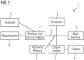
- Fig.1 illustrates an example of a data processing system in which an embodiment of the present disclosure may be implemented, for example a CAD system configured to perform processes as described herein.
- the data processing system 1 comprises a processor 2 connected to a local system bus 3.
- the local system bus connects the processor to a main memory 4 and graphics display adaptor 5, which may be connected to a display 6.
- the data processing system may communicate with other systems via a wireless user interface adapter connected to the local system bus 3, or via a wired network, e.g. to a local area network.
- Additional memory 8 may also be connected via the local system bus.
- a suitable adaptor such as wireless user interface adapter 7, for other peripheral devices, such as a keyboard 9 and mouse 10, or other pointing device, allows the user to provide input to the data processing system.
- peripheral devices may include one or more I/O controllers such as USB controllers, Bluetooth controllers, and/or dedicated audio controllers (connected to speakers and/or microphones). It should also be appreciated that various peripherals may be connected to the USB controller (via various USB ports) including input devices (e.g., keyboard, mouse, touch screen, trackball, camera, microphone, scanners), output devices (e.g., printers, speakers), or any other type of device that is operative to provide inputs or receive outputs from the data processing system. Further it should be appreciated that many devices referred to as input devices or output devices may both provide inputs and receive outputs of communications with the data processing system.
- I/O controllers such as USB controllers, Bluetooth controllers, and/or dedicated audio controllers (connected to speakers and/or microphones).
- various peripherals may be connected to the USB controller (via various USB ports) including input devices (e.g., keyboard, mouse, touch screen, trackball, camera, microphone, scanners), output devices (e.g., printers, speakers), or any other type of
- peripheral hardware connected to the I/O controllers may include any type of device, machine, or component that is configured to communicate with a data processing system.
- systems may use other types of input devices to provide inputs for manipulating objects such as a mouse, pointer, touch pad, drawing tablet, track ball, joystick, keypad, keyboard, camera, motion sensing device that captures motion gestures, or any other type of input device capable of providing the inputs described herein.
- a user may wish to model a design for an object, generate manufacturing instructions for manufacturing that object, or make modifications to the design or manufacturing instructions.
- the present disclosure relates to a system and method for controlling behaviour in a 2-dimensional or 3-dimensional parametric model.
- designing a system, or article for manufacture it is important that the shape as modelled for the design can actually be manufactured. There may be limitations on the system or articles imposed by the material properties of the material that is to be used to manufacture the article.
- limiting maximum curvature helps to give a curve shape which is pleasing to the eye, i.e. one that does not pass through the interpolation points too tightly
- limiting maximum curvature is a critical parameter for routing applications, where it is important to ensure that paths modelling wires and pipes do not exceed the maximum curvature allowed by the relevant physical materials from which those wires or pipes are to be manufactured.
- the model of the system needs to take account the practicality of actually manufacturing a wire or pipe, or other length of a product to have the given curvature that the design shows at each position along its length. Changing the location of another product in the system may result in the line of cable run or pipe run being forced into too tight a curve to be successfully manufactured.
- the method of the present disclosure provides a way of finding the optimal shape for the spline in a way that is relatively fast - the optimized shape is calculated in O(n) time, where n is the number of interpolation points and with a solution which is generally stable to small changes in the interpolation point positions.
- the method is based on a received representation of an article, such as a cable run, or pipe work, or metalwork. Bends in the article designed to fit within a system, or around other products in the system, may be represented as a spline 20, for example a spline comprising cubic Bézier segments, which is a standard form for a spline.
- the method is used to limit the maximum curvature of the spline.
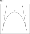
- each cubic Bézier segment comprises four control points ( C 1- C 4), as shown in Fig.2 .
- the curve 20 has various key geometric properties, regardless of the positions of the control points.
- C 1 is geometrically coincident to the start of the curve
- C 4 is geometrically coincident to the end of the curve
- the start of the curve is tangent to a line 21 between C 1 and C 2
- the end of the curve is tangent to a line 22 between C3 and C4.
- a spline representation is allocated in the model and processed as described hereinafter.
- the description refers to the spline or curves of the model representing a part of an article to be manufactured.
- An interpolating spline may be constructed using a series of such cubic Bézier segments 20.
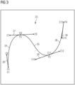
- An example of such a curve 23, or interpolating spline, interpolating the points P1, P2, P3 and P4 is shown in Fig.3 .
- the spline 23 is a piecewise cubic Bézier curve comprising three cubic Bézier segments, or curves 24, 25, 26.
- the end control points C8, C11 of each segment are shared with the previous and next segments, i.e. the first segment is between C5 and C8, the second between C8 and C11 and the third segment is between C11 and C13. This ensures that the curve is C0 continuous, i.e. with shared end control points, the overall curve will not have any gaps.
- This example may be generalised to n interpolation points P1 to Pn, for which the curve 23 comprises n-1 Bézier segments 24, 25, 26, with 3(n-1) +1 control points.
- This example shows the simplest construction for a piecewise Bézier spline, with a single Bézier curve or segment between two interpolation points, but it is also possible to have more than one Bézier curve, or segment, between each pair of interpolation points. This has advantages for minimizing the curvature, since there are more freedoms for the curve.
- the method described applies equally to those more complex curves.
- a cable run with a more complex shape may be represented using multiple Bézier curves between interpolation points. Using more Bézier segments allows a solution with a slightly higher maximum radius of curvature.
- the present disclosure provides a method of ensuring that the generated curve does not exceed a given global maximum curvature, k.
- this value k is under the control of the user.
- the value may be provided directly as part of the method, for example, by user input, or extracted from a store, the value having been determined in an earlier step.
- the value may be calculated as part of the method of the present disclosure, using received inputs relating to the material properties or other parameters which control the behaviour of the material from which the part will be manufactured and so limit the amount of curvature that the part can have.
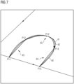
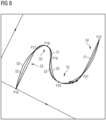
- the method of the present disclosure stars by receiving a representation of the article in 2-dimensions, or in 3-dimensions. That representation may be described as an initial piecewise cubic Bézier curve, for example curves 40, 50 as shown in Figs.7 and 8 and described in more detail below.
- the maximum curvature of the original curve, or the maximum curvature of each of the segments of the curve, as appropriate are measured. The measured curvature is then compared with the determined maximum permissible curvature, for given constraints of the article.
- the representation of the article as represented by the curve is deemed acceptable and that representation may be stored for use in manufacturing, or used in further processing. If the measured curvature is found to exceed the maximum permissible curvature, then further steps are required to obtain an acceptable amount of curvature. In one case, the next step may be to generate an optimal piecewise cubic Bézier curve through the same interpolation points. This optimal curve is one having the lowest curvature possible with the same number of Bézier intervals as the original curve. This is described in more detail below.
- the maximum curvature of the curve in this case, the optimal curve, is measured.
- the measured curvature is then compared with the determined maximum permissible curvature, for given constraints of the article. If the measured curvature still exceeds the determined maximum permissible curvature, then the process stops, typically with an error indication, as it is not possible to achieve a better solution than that of the optimal curve. In response a user may need to adjust the interpolation positions slightly, or possibly choose a different material from which to make the article and hence change the constraints. However, if the measured curvature does not exceed the determined maximum permissible curvature, when using an optimal curve, then further steps may be taken to improve upon that optimal, lowest possible curvature, curve.
- Another option, for a design made up of several segments, some of which are within the acceptable maximum curvature and some of which are not, is to keep the segments that are acceptable and then try modifications to the ones that are not acceptable to obtain a curvature that is within the limits.
- the whole curve representing the path of the cables or pipes, as modified, is then saved. This may be done by choosing a section of curve which needs to be adjusted, then fixing the tangent directions at the start and end of that section. This gives a sub-curve to optimise using the method as described. If no solution is found, the region may be expanded repeatedly, until it comprises the whole curve.
- the approach outlined here is to note that, for the case of three points, the lowest curvature path is an arc interpolating the points. Note that, in general, this isn't the case for more than three points.
- many real world interpolation problems are characterised by straight line segments (equivalent to infinite radius circles here) and right-angled bends (quarter circles). In these cases, the lowest curvature path is often a series of lines and arcs. Even for more general cases, such a construction is also close to optimal. We therefore seek an optimal curve which is a Bézier curve approximation to a sequence of arc and straight line segments.
- the first step in the calculation of the optimal curve is to fit a series of exact arc segments to the interpolation points, using the following method:
- Fig.4 The result of the process, for a case involving four interpolation points, is shown in Fig.4 .
- a series of three arcs 31, 32, 33 are fitted to four interpolation points P5 to P8.
- the parameters of the arcs are uniquely determined. Due to the choice of ⁇ 1, the procedure described in steps 1 to 5 above does not generally give the series of arc segments with lowest curvature through the interpolation points.
- ⁇ 1 is varied, using standard 1D minimization techniques, until the curve with the lowest curvature is found, i.e. the minimum radius of the string of arcs is maximised.
- the final step in determining the optimal curve is to convert the series of arcs to a piecewise cubic Bézier representation.
- the end points of each Bézier segment are known, they are the relevant interpolation points, and the end directions are also known, from the directions of the arcs through the interpolation points.
- the only freedom for each Bézier segment is therefore the length of C1-C2 and C3-C4 (see Fig.1 ). Since the aim is to approximate an arc, the lengths of C1-C and C3-C4 are set to be equal to one another, leaving only a single degree of freedom for each Bézier segment 20.
- the single degree of freedom may be constrained in various standard ways.
- the simple requirement that the mid-point M of the Bézier segment 34 is geometrically coincident to the midpoint of the relevant arc 35 may be adopted.
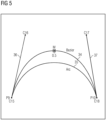
- This procedure enables a Bézier curve to approximate circular arcs, i.e. those with internal angles of ⁇ 180°, to within a few percent, for example, as shown in Fig.5.
- Fig.5 illustrates fitting a Bézier segment 34 to an arc 35.
- the lengths of line C15-C16 36 and line C17-C18 37 are equal.
- Making midpoint M coincident to the middle of the arc 35 gives a Bézier curve 34 which is almost indistinguishable from the arc itself.
- interpolation methods are possible and an example of an interpolation method that may be used is described below. However, other interpolation methods may also be valid.
- Each curve may be described using the positions of the interpolation points ( P i ), the direction of the curve 38, 39 at each interpolation point ( ⁇ i ), and the distance to the previous and next Bézier control points ( d 1,i and d 2,i ) , for example as illustrated in Fig.6 .
- Fig.6 provides a definition of C21 and C23 in terms of C22, d1, d2 and ⁇ . The start of the curve is tangent to a line between C19 and C20; and the end of the curve is tangent to a line between C24 and C25.
- the resulting family of G1 continuous curves 40, 42, 44 for example as shown in Figs.7 and 8 , varies smoothly between the original and optimal curves.
- x is varied from 0 to 1 in order to find the curve with the specified maximum curvature.
- Figs.7 and 8 Some examples of the method are shown in Figs.7 and 8 .
- an original Bézier curve 40, 50, the optimal curve 41, 51, and an arbitrary intermediate curve 42, 52 obtained by interpolating between the two previous curves 40, 41, 50, 51 are shown.
- the initial curve 40, optimal curve 41 and intermediate curve 42 are shown for a case with five interpolation points P11 to P15.
- the optimal curve 41 comprises straight line segments 43, 44 between P11-P12 and P14-P15, with an arc 45 from P12 to P14.
- the optimal curve 51 is shown for a case with seven interpolation points, P16 to P22.
- the optimal curve 51 comprises straight line segments 53, 54 between P16-P17 and P21-P22, with two arcs 55 from P17 to P19 and P19 to P21.
- the disclosure provides a method of modelling and article to be manufactured which includes parts where curvature is constrained by the material or other properties of the article and which is able to limit the maximum curvature of a piecewise Bézier curve by constructing an optimal curve, which in the examples shown comprises a spline comprising arc segments and applying an interpolation procedure to find an intermediate curve of the desired curvature.
- the method allows for custom spline functionality and control of maximum curvature of the spline and hence of the product that the spline represents.
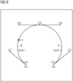
- Fig.9 illustrates an example of where two cubic Bézier segments C26 to C29 and C29 to C32 are used between a pair of interpolation points P23 and P24.
- the large arc shape is much better represented by two Bézier segments 56, 57 than it would be by a single curve.
- the choice of whether to use a single Bézier curve, or more than one Bézier segment is a trade-off between performance and obtaining the best possible shape.
- the two segment option allows the optimal curve to be approximated more closely.
- a rational spline could be used to represent the arc segments of the optimal curve exactly.
- the rational spline segment has more freedoms (control point weights) than the Bezier, so it is possible to represent the arcs more exactly.
- the weights are then interpolated from the initial to optimal splines.
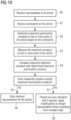
- Fig. 10 is a flow diagram illustrating the main elements of the method of the present disclosure.
- a representation of an article to be manufactured such as pipe work, metalwork, or cabling, or other length of material, is received 60 by the data processing system.
- Constraints for the article are received 61, which are associated with a parameter of the article, such as the material properties of the material from which the article is to be made.
- a maximum permissible curvature of one or more parts of the article is determined 62. For example, certain materials will not be able to bend beyond a certain amount of curvature without cracking or breaking, or it may not be possible to form an article in that material if the curvature exceeds the determined maximum.
- the maximum curvature of one or more parts of the article as designed in the model is measured 63 and this measured maximum curvature is compared 64 with the determined maximum permissible curvature. If the measured curvature does not exceed 66 the determined maximum permissible curvature, then the received representation for the article is stored 66 and may be used subsequently in a manufacturing step. If the measured curvature exceeds 67 the determined maximum permissible curvature, then typically an error indication is provided 68. In response to this, modifications may be made to the design representation before repeating from compare step to adapt the design, so that it is more likely to comply with the constraints. When a design has been determined which does meet the constraints applicable for a particular product made in a particular material, then the representation of the article is stored. The representation may be converted into a set of manufacturing instructions for a computer controlled machine.
- the representation for those parts of the article which do not exceed the determined maximum permissible curvature may be stored a revised representation for the parts of the article which exceed the determined maximum permissible curvature is generated. The process may then be repeated from the comparing step and the revised representation stored for those parts of the article which meet the constraints until a complete representation meeting the constraints has been built up.
- the representation of the article may be generated by simulating a system incorporating the article to be manufactured.
- the parameters of the article, from which the constraints are derived typically comprise a physical property of a material from which a part of the article is to be manufactured.
- the constraints may be received from an external source, or extracted from a store.
- a method of generating an article comprising a plurality of parts may comprise modelling the article in accordance with a method as described with respect to Fig. 10 , inputting the stored representation, or dataset, for one or more parts of the article, or a set of manufacturing instructions derived from that dataset, to a computer controlled machine and replicating the parts of the article in the material for which it has been designed, or a material with equivalent properties, using the computer controlled machine.
- the method is capable of returning an optimal solution for an important class of input interpolation points, those where the ideal path comprises lines and arcs. This is achieved by the choice of shape for the optimal spline.
- the method has the advantage of being very fast compared to other, more numerical, methods by using of numerical techniques in a single variable.
- the solution means that the curve shape is, apart from critical points, stable to small changes in the interpolation point positions. This is important for integration with other applications such as constraint solving using the D-Cubed Dimensional Constraint Managers (D-cubed DCM).
- An operating system included in the data processing system enables an output from the system to be displayed to the user on display 6 and the user to interact with the system.
- Examples of operating systems that may be used in a data processing system may include Microsoft WindowsTM, LinuxTM, UNIXTM, iOSTM, and AndroidTM operating systems.
- data processing system 1 may be implemented as in a networked environment, distributed system environment, virtual machines in a virtual machine architecture, and/or cloud environment.
- the processor 2 and associated components may correspond to a virtual machine executing in a virtual machine environment of one or more servers.
- virtual machine architectures include VMware ESCi, Microsoft Hyper-V, Xen, and KVM.
- the hardware depicted for the data processing system 1 may vary for particular implementations.
- the data processing system 1 in this example may correspond to a computer, workstation, and/or a server.
- alternative embodiments of a data processing system may be configured with corresponding or alternative components such as in the form of a mobile phone, tablet, controller board or any other system that is operative to process data and carry out functionality and features described herein associated with the operation of a data processing system, computer, processor, and/or a controller discussed herein.
- the depicted example is provided for the purpose of explanation only and is not meant to imply architectural limitations with respect to the present disclosure.
- the data processing system 1 may be connected to the network (not a part of data processing system 1), which can be any public or private data processing system network or combination of networks, as known to those of skill in the art, including the Internet.
- Data processing system 1 can communicate over the network with one or more other data processing systems such as a server (also not part of the data processing system 1).
- an alternative data processing system may correspond to a plurality of data processing systems implemented as part of a distributed system in which processors associated with several data processing systems may be in communication by way of one or more network connections and may collectively perform tasks described as being performed by a single data processing system.
- a data processing system such a system may be implemented across several data processing systems organized in a distributed system in communication with each other via a network.
- machine usable/readable or computer usable/readable mediums include: nonvolatile, hard-coded type mediums such as read only memories (ROMs) or erasable, electrically programmable read only memories (EEPROMs), and user-recordable type mediums such as floppy disks, hard disk drives and compact disk read only memories (CD-ROMs) or digital versatile disks (DVDs).
- ROMs read only memories
- EEPROMs electrically programmable read only memories
- user-recordable type mediums such as floppy disks, hard disk drives and compact disk read only memories (CD-ROMs) or digital versatile disks (DVDs).
Landscapes
- Engineering & Computer Science (AREA)
- Physics & Mathematics (AREA)
- Theoretical Computer Science (AREA)
- Geometry (AREA)
- General Physics & Mathematics (AREA)
- Computer Hardware Design (AREA)
- Evolutionary Computation (AREA)
- General Engineering & Computer Science (AREA)
- Computational Mathematics (AREA)
- Mathematical Analysis (AREA)
- Mathematical Optimization (AREA)
- Pure & Applied Mathematics (AREA)
- Image Generation (AREA)
- Numerical Control (AREA)
Claims (7)
- Verfahren zum Generieren eines Artikels, umfassend:Empfangen einer Darstellung des Artikels als eine anfängliche stückweise kubische Bezierkurve in 2 Dimensionen oder in 3 Dimensionen;Empfangen einer oder mehrerer Einschränkungen für den Artikel, die einem Parameter des Artikels zugeordnet sind;Bestimmen einer maximal zulässigen Krümmung eines oder mehrerer Teile des Artikels aus den Einschränkungen des Artikels, wobei der Parameter des Artikels eine physikalische Eigenschaft eines Materials umfasst, aus dem ein Teil des Artikels hergestellt werden soll;Messen der maximalen Krümmung des einen oder der mehreren Teile des Artikels in der empfangenen Darstellung;Vergleichen der gemessenen maximalen Krümmung mit der aus den Einschränkungen des Artikels bestimmten maximal zulässigen Krümmung; und,wenn die gemessene maximale Krümmung der mindestens einen oder der mehreren Teile die ermittelte maximal zulässige Krümmung überschreitet, Bereitstellen einer Fehleranzeige; oderwenn die gemessene maximale Krümmung jedes des einen oder der mehreren Teile die ermittelte maximal zulässige Krümmung nicht überschreitet,Speichern der empfangenen Darstellung für den Artikel;Eingeben der gespeicherten Darstellung für das eine oder die mehreren Teile des Artikels in eine rechnergesteuerte Maschine; undNachbilden der Teile des Artikels in einem Material unter Verwendung der rechnergesteuerten Maschine,wobei das Verfahren als Reaktion auf die Fehleranzeige ferner das Empfangen von Modifikationen an der Entwurfsdarstellung oder an den Einschränkungen umfasst; und Wiederholen aus dem Vergleichsschritt oder aus dem Bestimmungsschritt entsprechend, bis ein konformer Entwurf erreicht wird oder der Entwurf abgelehnt wird.
- Verfahren nach Anspruch 1, wobei das Verfahren ferner das Speichern der Darstellung für diejenigen Teile des Artikels, die die ermittelte maximal zulässige Krümmung nicht überschreiten; und das Generieren einer überarbeiteten Darstellung für die Teile des Artikels, die die ermittelte maximal zulässige Krümmung überschreiten; und das anschließende Wiederholen des Verfahrens aus dem Vergleichsschritt umfasst.
- Verfahren nach Anspruch 2, wobei das Generieren der überarbeiteten Darstellung das Generieren einer Zwischenkurve aus einer optimalen Kurve durch Interpolation umfasst.
- Verfahren nach einem der vorhergehenden Ansprüche, wobei die Darstellung des Artikels durch Simulieren eines Systems generiert wird, das den herzustellenden Artikel beinhaltet.
- Verfahren nach einem der vorhergehenden Ansprüche, wobei die Einschränkungen von einer externen Quelle empfangen oder aus einem Speicher extrahiert werden können.
- Ein Datenverarbeitungssystem beinhaltet einen Prozessor; und einen zugänglichen Speicher, wobei das Datenverarbeitungssystem insbesondere konfiguriert ist, um die folgenden Schritte durchzuführen:Empfangen einer Darstellung des Artikels als eine anfängliche stückweise kubische Bezierkurve in 2 Dimensionen oder in 3 Dimensionen;Empfangen einer oder mehrerer Einschränkungen für den Artikel, die einem Parameter des Artikels zugeordnet sind, wobei der Parameter des Artikels eine physikalische Eigenschaft eines Materials umfasst, aus dem ein Teil des Artikels hergestellt werden soll;Bestimmen einer maximal zulässigen Krümmung eines oder mehrerer Teile des Artikels aus den Einschränkungen des Artikels;Messen der maximalen Krümmung des einen oder der mehreren Teile des Artikels in der empfangenen Darstellung;Vergleichen der gemessenen maximalen Krümmung mit der aus den Einschränkungen des Artikels bestimmten maximal zulässigen Krümmung; und,wenn die gemessene maximale Krümmung des mindestens einen oder der mehreren Teile die ermittelte maximal zulässige Krümmung überschreitet, Bereitstellen einer Fehleranzeige; oder,wenn die gemessene maximale Krümmung jedes des einen oder der mehreren Teile die ermittelte maximal zulässige Krümmung nicht überschreitet,Speichern der empfangenen Darstellung für den ArtikelEingeben der gespeicherten Darstellung für das eine oder die mehreren Teile des Artikels in eine rechnergesteuerte Maschine; undNachbilden der Teile des Artikels in einem Material unter Verwendung der rechnergesteuerten Maschine,wobei das Verfahren als Reaktion auf die Fehleranzeige ferner das Empfangen von Modifikationen an der Entwurfsdarstellung oder an den Einschränkungen umfasst; und Wiederholen aus dem Vergleichsschritt oder aus dem Bestimmungsschritt entsprechend, bis ein konformer Entwurf erreicht wird, oder der Entwurf abgelehnt wird.
- Nicht transitorisches computerlesbares Medium, das mit ausführbaren Anweisungen codiert ist, die beim Ausführen ein oder mehrere Datenverarbeitungssysteme dazu veranlassen, ein Verfahren zum Generieren eines Artikels durchzuführen, wobei das Verfahren mit einem Datenverarbeitungssystem durchgeführt wird, wobei das Verfahren Folgendes umfasst:Empfangen einer Darstellung des Artikels als eine anfängliche stückweise kubische Bezierkurve in 2 Dimensionen oder in 3 Dimensionen;Empfangen einer oder mehrerer Einschränkungen für den Artikel, die einem Parameter des Artikels zugeordnet sind;Bestimmen einer maximal zulässigen Krümmung eines oder mehrerer Teile des Artikels aus den Einschränkungen des Artikels, wobei der Parameter des Artikels eine physikalische Eigenschaft eines Materials umfasst, aus dem ein Teil des Artikels hergestellt werden soll;Messen der maximalen Krümmung des einen oder der mehreren Teile des Artikels in der empfangenen Darstellung;Vergleichen der gemessenen maximalen Krümmung mit der aus den Einschränkungen des Artikels bestimmten maximal zulässigen Krümmung; und,wenn die gemessene maximale Krümmung des mindestens einen oder der mehreren Teile die ermittelte maximal zulässige Krümmung überschreitet, Bereitstellen einer Fehleranzeige; oder,wenn die gemessene maximale Krümmung jedes des einen oder der mehreren Teile die ermittelte maximal zulässige Krümmung nicht überschreitet,Speichern der empfangenen Darstellung für den Artikel;Eingeben der gespeicherten Darstellung für das eine oder die mehreren Teile des Artikels in eine rechnergesteuerte Maschine; undNachbilden der Teile des Artikels in einem Material unter Verwendung der rechnergesteuerten Maschine,wobei das Verfahren als Reaktion auf die Fehleranzeige ferner das Empfangen von Modifikationen an der Entwurfsdarstellung oder an den Einschränkungen umfasst; und Wiederholen aus dem Vergleichsschritt oder aus dem Bestimmungsschritt entsprechend, bis ein konformer Entwurf erreicht wird, oder der Entwurf abgelehnt wird.
Applications Claiming Priority (1)
| Application Number | Priority Date | Filing Date | Title |
|---|---|---|---|
| PCT/EP2017/081054 WO2019105562A1 (en) | 2017-11-30 | 2017-11-30 | A method of operating a cad system model for modelling an article to be manufactured |
Publications (3)
| Publication Number | Publication Date |
|---|---|
| EP3718031A1 EP3718031A1 (de) | 2020-10-07 |
| EP3718031B1 true EP3718031B1 (de) | 2025-01-29 |
| EP3718031C0 EP3718031C0 (de) | 2025-01-29 |
Family
ID=60702658
Family Applications (1)
| Application Number | Title | Priority Date | Filing Date |
|---|---|---|---|
| EP17816588.2A Active EP3718031B1 (de) | 2017-11-30 | 2017-11-30 | Verfahren zum betrieb eines cad-systemmodells zur modellierung eines zu herstellenden artikels |
Country Status (4)
| Country | Link |
|---|---|
| US (1) | US11468211B2 (de) |
| EP (1) | EP3718031B1 (de) |
| CN (1) | CN110291522A (de) |
| WO (1) | WO2019105562A1 (de) |
Families Citing this family (6)
| Publication number | Priority date | Publication date | Assignee | Title |
|---|---|---|---|---|
| CN112269965B (zh) * | 2020-08-10 | 2024-04-05 | 中国北方车辆研究所 | 一种非完整约束条件下的连续曲率路径优化方法 |
| CN112379636B (zh) * | 2020-11-13 | 2021-06-22 | 哈尔滨工业大学 | 一种针对光学晶体表面损伤点的变步距微铣削修复刀具轨迹生成方法 |
| JP2022136838A (ja) * | 2021-03-08 | 2022-09-21 | 東芝インフォメーションシステムズ株式会社 | 情報処理装置及び表示方法 |
| JP7756623B2 (ja) * | 2022-11-25 | 2025-10-20 | 株式会社管総研 | 管路図設計方法、管路図設計装置及び管路図設計プログラム |
| CN117351109B (zh) * | 2023-09-05 | 2024-06-07 | 中交第二公路勘察设计研究院有限公司 | 一种盾构隧道的截面曲线重构方法 |
| CN117576254B (zh) * | 2024-01-15 | 2024-04-30 | 厦门民航凯亚有限公司 | 一种计算行李到达提取转盘后的运动轨迹的方法 |
Citations (2)
| Publication number | Priority date | Publication date | Assignee | Title |
|---|---|---|---|---|
| US20050240383A1 (en) * | 2003-05-19 | 2005-10-27 | Fujitsu Limited | Harness design supporting apparatus and computer-readable recording medium recording harness design supporting program |
| EP2120169A1 (de) * | 2007-01-10 | 2009-11-18 | Fujitsu Limited | Routenkurvenerzeugungssystem, verfahren und programm |
Family Cites Families (8)
| Publication number | Priority date | Publication date | Assignee | Title |
|---|---|---|---|---|
| US7218326B1 (en) * | 2003-06-11 | 2007-05-15 | Autodesk, Inc. | Spline manipulation tool |
| DE112005000451B4 (de) * | 2004-02-27 | 2020-02-13 | Thk Co., Ltd. | Designverfahren für ein Industrieerzeugnis unter Verwendung einer Klothoidenkurve, und Verfahren und Vorrichtung zur numerischen Steuerung unter Verwendung der Klothoidenkurve |
| US8142187B2 (en) * | 2005-09-23 | 2012-03-27 | Orametrix, Inc. | Method and apparatus for digitally evaluating insertion quality of customized orthodontic arch wire |
| US8473257B2 (en) * | 2010-03-26 | 2013-06-25 | Siemens Product Lifecycle Management Software Inc. | System and method for constraining curves in a CAD system |
| CN102509339B (zh) * | 2011-10-10 | 2014-04-02 | 武汉大学 | 一种带纹理约束的三维模型顶点聚类简化方法 |
| US9886527B2 (en) * | 2013-01-16 | 2018-02-06 | Autodesk, Inc. | Determining feasible splines with engineering constraints using projection methods |
| JP5845228B2 (ja) * | 2013-10-23 | 2016-01-20 | ファナック株式会社 | 工具経路曲線化装置 |
| US10769321B2 (en) * | 2015-03-25 | 2020-09-08 | Alex E. Paris Contracting Co., Inc. | Pipeline design and layout system and method therefor |
-
2017
- 2017-11-30 CN CN201780085681.8A patent/CN110291522A/zh active Pending
- 2017-11-30 US US16/480,714 patent/US11468211B2/en active Active
- 2017-11-30 EP EP17816588.2A patent/EP3718031B1/de active Active
- 2017-11-30 WO PCT/EP2017/081054 patent/WO2019105562A1/en not_active Ceased
Patent Citations (2)
| Publication number | Priority date | Publication date | Assignee | Title |
|---|---|---|---|---|
| US20050240383A1 (en) * | 2003-05-19 | 2005-10-27 | Fujitsu Limited | Harness design supporting apparatus and computer-readable recording medium recording harness design supporting program |
| EP2120169A1 (de) * | 2007-01-10 | 2009-11-18 | Fujitsu Limited | Routenkurvenerzeugungssystem, verfahren und programm |
Also Published As
| Publication number | Publication date |
|---|---|
| US20210133365A1 (en) | 2021-05-06 |
| EP3718031C0 (de) | 2025-01-29 |
| EP3718031A1 (de) | 2020-10-07 |
| WO2019105562A1 (en) | 2019-06-06 |
| US11468211B2 (en) | 2022-10-11 |
| CN110291522A (zh) | 2019-09-27 |
Similar Documents
| Publication | Publication Date | Title |
|---|---|---|
| EP3718031B1 (de) | Verfahren zum betrieb eines cad-systemmodells zur modellierung eines zu herstellenden artikels | |
| US11016470B2 (en) | Conversion of mesh geometry to watertight boundary representation | |
| KR102242138B1 (ko) | 디지털 트윈 기반의 배관 설계 모델링 장치 및 방법 | |
| US10430524B1 (en) | Constructing multi-element features using a 3D CAD system | |
| EP2120169A1 (de) | Routenkurvenerzeugungssystem, verfahren und programm | |
| US20150127301A1 (en) | Updating A CAD Model To Reflect Global Or Local Shape Changes | |
| US10943037B2 (en) | Generating a CAD model from a finite element mesh | |
| US12437129B2 (en) | Modelling method and system | |
| US20160004790A1 (en) | Seam modification for 3d cad models | |
| EP3168761A1 (de) | Sicherstellung, dass tunnelkonstruktionen innerhalb bestimmter konstruktionsparameter und -toleranzen bleiben | |
| US10204184B2 (en) | Apparatus and method for modeling cultural heritage building | |
| US20050285855A1 (en) | Method of rapidly building multiple three-dimensional pipes | |
| CN111656354B (zh) | 操作用于对待制造物品建模的cad系统模型的方法 | |
| CN110235131B (zh) | 用于模拟工业机器人的机器人程序的方法及系统 | |
| US20160357878A1 (en) | Modelling method and system | |
| US20170285615A1 (en) | Modelling method and system | |
| US9135730B2 (en) | Curve chain connections under surface, distance, and shape constraints | |
| US9400854B2 (en) | Aerospace joggle on multiple adjacent web faces with intersecting runouts | |
| CN120188197A (zh) | 网格结构中的顶点链优化 | |
| US20240212281A1 (en) | Mixed sheet extension | |
| WO2025250134A1 (en) | Mesh refinement method | |
| JP4851542B2 (ja) | ルート曲線生成システム、方法、及びプログラム | |
| WO2025023935A1 (en) | Mesh offsetting method | |
| CN118247450A (zh) | 基于三次样条插值的三维地形自动建模方法及装置 |
Legal Events
| Date | Code | Title | Description |
|---|---|---|---|
| STAA | Information on the status of an ep patent application or granted ep patent |
Free format text: STATUS: UNKNOWN |
|
| STAA | Information on the status of an ep patent application or granted ep patent |
Free format text: STATUS: THE INTERNATIONAL PUBLICATION HAS BEEN MADE |
|
| PUAI | Public reference made under article 153(3) epc to a published international application that has entered the european phase |
Free format text: ORIGINAL CODE: 0009012 |
|
| STAA | Information on the status of an ep patent application or granted ep patent |
Free format text: STATUS: REQUEST FOR EXAMINATION WAS MADE |
|
| 17P | Request for examination filed |
Effective date: 20190808 |
|
| AK | Designated contracting states |
Kind code of ref document: A1 Designated state(s): AL AT BE BG CH CY CZ DE DK EE ES FI FR GB GR HR HU IE IS IT LI LT LU LV MC MK MT NL NO PL PT RO RS SE SI SK SM TR |
|
| AX | Request for extension of the european patent |
Extension state: BA ME |
|
| DAV | Request for validation of the european patent (deleted) | ||
| DAX | Request for extension of the european patent (deleted) | ||
| STAA | Information on the status of an ep patent application or granted ep patent |
Free format text: STATUS: EXAMINATION IS IN PROGRESS |
|
| 17Q | First examination report despatched |
Effective date: 20220324 |
|
| RAP3 | Party data changed (applicant data changed or rights of an application transferred) |
Owner name: SIEMENS INDUSTRY SOFTWARE LIMITED |
|
| REG | Reference to a national code |
Ref legal event code: R079 Free format text: PREVIOUS MAIN CLASS: G06F0017500000 Ipc: G06F0030000000 Ref country code: DE Ref document number: 602017087567 Country of ref document: DE |
|
| GRAP | Despatch of communication of intention to grant a patent |
Free format text: ORIGINAL CODE: EPIDOSNIGR1 |
|
| STAA | Information on the status of an ep patent application or granted ep patent |
Free format text: STATUS: GRANT OF PATENT IS INTENDED |
|
| RIC1 | Information provided on ipc code assigned before grant |
Ipc: G06F 113/16 20200101ALI20240823BHEP Ipc: G06F 113/14 20200101ALI20240823BHEP Ipc: G06F 30/00 20200101AFI20240823BHEP |
|
| INTG | Intention to grant announced |
Effective date: 20240927 |
|
| GRAS | Grant fee paid |
Free format text: ORIGINAL CODE: EPIDOSNIGR3 |
|
| GRAA | (expected) grant |
Free format text: ORIGINAL CODE: 0009210 |
|
| STAA | Information on the status of an ep patent application or granted ep patent |
Free format text: STATUS: THE PATENT HAS BEEN GRANTED |
|
| AK | Designated contracting states |
Kind code of ref document: B1 Designated state(s): AL AT BE BG CH CY CZ DE DK EE ES FI FR GB GR HR HU IE IS IT LI LT LU LV MC MK MT NL NO PL PT RO RS SE SI SK SM TR |
|
| REG | Reference to a national code |
Ref country code: GB Ref legal event code: FG4D |
|
| REG | Reference to a national code |
Ref country code: CH Ref legal event code: EP |
|
| REG | Reference to a national code |
Ref country code: DE Ref legal event code: R096 Ref document number: 602017087567 Country of ref document: DE |
|
| REG | Reference to a national code |
Ref country code: IE Ref legal event code: FG4D |
|
| U01 | Request for unitary effect filed |
Effective date: 20250218 |
|
| U07 | Unitary effect registered |
Designated state(s): AT BE BG DE DK EE FI FR IT LT LU LV MT NL PT RO SE SI Effective date: 20250224 |
|
| PG25 | Lapsed in a contracting state [announced via postgrant information from national office to epo] |
Ref country code: RS Free format text: LAPSE BECAUSE OF FAILURE TO SUBMIT A TRANSLATION OF THE DESCRIPTION OR TO PAY THE FEE WITHIN THE PRESCRIBED TIME-LIMIT Effective date: 20250429 |
|
| PG25 | Lapsed in a contracting state [announced via postgrant information from national office to epo] |
Ref country code: PL Free format text: LAPSE BECAUSE OF FAILURE TO SUBMIT A TRANSLATION OF THE DESCRIPTION OR TO PAY THE FEE WITHIN THE PRESCRIBED TIME-LIMIT Effective date: 20250129 |
|
| PG25 | Lapsed in a contracting state [announced via postgrant information from national office to epo] |
Ref country code: ES Free format text: LAPSE BECAUSE OF FAILURE TO SUBMIT A TRANSLATION OF THE DESCRIPTION OR TO PAY THE FEE WITHIN THE PRESCRIBED TIME-LIMIT Effective date: 20250129 |
|
| PG25 | Lapsed in a contracting state [announced via postgrant information from national office to epo] |
Ref country code: NO Free format text: LAPSE BECAUSE OF FAILURE TO SUBMIT A TRANSLATION OF THE DESCRIPTION OR TO PAY THE FEE WITHIN THE PRESCRIBED TIME-LIMIT Effective date: 20250429 Ref country code: IS Free format text: LAPSE BECAUSE OF FAILURE TO SUBMIT A TRANSLATION OF THE DESCRIPTION OR TO PAY THE FEE WITHIN THE PRESCRIBED TIME-LIMIT Effective date: 20250529 |
|
| PG25 | Lapsed in a contracting state [announced via postgrant information from national office to epo] |
Ref country code: HR Free format text: LAPSE BECAUSE OF FAILURE TO SUBMIT A TRANSLATION OF THE DESCRIPTION OR TO PAY THE FEE WITHIN THE PRESCRIBED TIME-LIMIT Effective date: 20250129 |
|
| PG25 | Lapsed in a contracting state [announced via postgrant information from national office to epo] |
Ref country code: GR Free format text: LAPSE BECAUSE OF FAILURE TO SUBMIT A TRANSLATION OF THE DESCRIPTION OR TO PAY THE FEE WITHIN THE PRESCRIBED TIME-LIMIT Effective date: 20250430 |
|
| PG25 | Lapsed in a contracting state [announced via postgrant information from national office to epo] |
Ref country code: SM Free format text: LAPSE BECAUSE OF FAILURE TO SUBMIT A TRANSLATION OF THE DESCRIPTION OR TO PAY THE FEE WITHIN THE PRESCRIBED TIME-LIMIT Effective date: 20250129 |
|
| PG25 | Lapsed in a contracting state [announced via postgrant information from national office to epo] |
Ref country code: CZ Free format text: LAPSE BECAUSE OF FAILURE TO SUBMIT A TRANSLATION OF THE DESCRIPTION OR TO PAY THE FEE WITHIN THE PRESCRIBED TIME-LIMIT Effective date: 20250129 |
|
| PG25 | Lapsed in a contracting state [announced via postgrant information from national office to epo] |
Ref country code: SK Free format text: LAPSE BECAUSE OF FAILURE TO SUBMIT A TRANSLATION OF THE DESCRIPTION OR TO PAY THE FEE WITHIN THE PRESCRIBED TIME-LIMIT Effective date: 20250129 |