EP3717953B1 - Self-cleaning vehicle camera assemblies - Google Patents
Self-cleaning vehicle camera assemblies Download PDFInfo
- Publication number
- EP3717953B1 EP3717953B1 EP18883923.7A EP18883923A EP3717953B1 EP 3717953 B1 EP3717953 B1 EP 3717953B1 EP 18883923 A EP18883923 A EP 18883923A EP 3717953 B1 EP3717953 B1 EP 3717953B1
- Authority
- EP
- European Patent Office
- Prior art keywords
- housing
- vehicle camera
- assembly
- self
- cleaning assembly
- Prior art date
- Legal status (The legal status is an assumption and is not a legal conclusion. Google has not performed a legal analysis and makes no representation as to the accuracy of the status listed.)
- Active
Links
Images



Classifications
-
- B—PERFORMING OPERATIONS; TRANSPORTING
- B60—VEHICLES IN GENERAL
- B60S—SERVICING, CLEANING, REPAIRING, SUPPORTING, LIFTING, OR MANOEUVRING OF VEHICLES, NOT OTHERWISE PROVIDED FOR
- B60S1/00—Cleaning of vehicles
- B60S1/02—Cleaning windscreens, windows or optical devices
- B60S1/46—Cleaning windscreens, windows or optical devices using liquid; Windscreen washers
- B60S1/48—Liquid supply therefor
- B60S1/52—Arrangement of nozzles; Liquid spreading means
-
- G—PHYSICS
- G02—OPTICS
- G02B—OPTICAL ELEMENTS, SYSTEMS OR APPARATUS
- G02B27/00—Optical systems or apparatus not provided for by any of the groups G02B1/00 - G02B26/00, G02B30/00
- G02B27/0006—Optical systems or apparatus not provided for by any of the groups G02B1/00 - G02B26/00, G02B30/00 with means to keep optical surfaces clean, e.g. by preventing or removing dirt, stains, contamination, condensation
-
- B—PERFORMING OPERATIONS; TRANSPORTING
- B60—VEHICLES IN GENERAL
- B60R—VEHICLES, VEHICLE FITTINGS, OR VEHICLE PARTS, NOT OTHERWISE PROVIDED FOR
- B60R1/00—Optical viewing arrangements; Real-time viewing arrangements for drivers or passengers using optical image capturing systems, e.g. cameras or video systems specially adapted for use in or on vehicles
- B60R1/02—Rear-view mirror arrangements
- B60R1/06—Rear-view mirror arrangements mounted on vehicle exterior
- B60R1/0602—Rear-view mirror arrangements mounted on vehicle exterior comprising means for cleaning or deicing
-
- B—PERFORMING OPERATIONS; TRANSPORTING
- B60—VEHICLES IN GENERAL
- B60S—SERVICING, CLEANING, REPAIRING, SUPPORTING, LIFTING, OR MANOEUVRING OF VEHICLES, NOT OTHERWISE PROVIDED FOR
- B60S1/00—Cleaning of vehicles
- B60S1/02—Cleaning windscreens, windows or optical devices
- B60S1/46—Cleaning windscreens, windows or optical devices using liquid; Windscreen washers
- B60S1/48—Liquid supply therefor
- B60S1/481—Liquid supply therefor the operation of at least part of the liquid supply being controlled by electric means
- B60S1/482—Liquid supply therefor the operation of at least part of the liquid supply being controlled by electric means combined with the operation of windscreen wipers
-
- B—PERFORMING OPERATIONS; TRANSPORTING
- B60—VEHICLES IN GENERAL
- B60S—SERVICING, CLEANING, REPAIRING, SUPPORTING, LIFTING, OR MANOEUVRING OF VEHICLES, NOT OTHERWISE PROVIDED FOR
- B60S1/00—Cleaning of vehicles
- B60S1/02—Cleaning windscreens, windows or optical devices
- B60S1/46—Cleaning windscreens, windows or optical devices using liquid; Windscreen washers
- B60S1/48—Liquid supply therefor
- B60S1/52—Arrangement of nozzles; Liquid spreading means
- B60S1/522—Arrangement of nozzles; Liquid spreading means moving liquid spreading means, e.g. arranged in wiper arms
- B60S1/524—Arrangement of nozzles; Liquid spreading means moving liquid spreading means, e.g. arranged in wiper arms arranged in wiper blades
-
- B—PERFORMING OPERATIONS; TRANSPORTING
- B60—VEHICLES IN GENERAL
- B60S—SERVICING, CLEANING, REPAIRING, SUPPORTING, LIFTING, OR MANOEUVRING OF VEHICLES, NOT OTHERWISE PROVIDED FOR
- B60S1/00—Cleaning of vehicles
- B60S1/02—Cleaning windscreens, windows or optical devices
- B60S1/56—Cleaning windscreens, windows or optical devices specially adapted for cleaning other parts or devices than front windows or windscreens
-
- G—PHYSICS
- G03—PHOTOGRAPHY; CINEMATOGRAPHY; ANALOGOUS TECHNIQUES USING WAVES OTHER THAN OPTICAL WAVES; ELECTROGRAPHY; HOLOGRAPHY
- G03B—APPARATUS OR ARRANGEMENTS FOR TAKING PHOTOGRAPHS OR FOR PROJECTING OR VIEWING THEM; APPARATUS OR ARRANGEMENTS EMPLOYING ANALOGOUS TECHNIQUES USING WAVES OTHER THAN OPTICAL WAVES; ACCESSORIES THEREFOR
- G03B17/00—Details of cameras or camera bodies; Accessories therefor
- G03B17/02—Bodies
-
- G—PHYSICS
- G03—PHOTOGRAPHY; CINEMATOGRAPHY; ANALOGOUS TECHNIQUES USING WAVES OTHER THAN OPTICAL WAVES; ELECTROGRAPHY; HOLOGRAPHY
- G03B—APPARATUS OR ARRANGEMENTS FOR TAKING PHOTOGRAPHS OR FOR PROJECTING OR VIEWING THEM; APPARATUS OR ARRANGEMENTS EMPLOYING ANALOGOUS TECHNIQUES USING WAVES OTHER THAN OPTICAL WAVES; ACCESSORIES THEREFOR
- G03B17/00—Details of cameras or camera bodies; Accessories therefor
- G03B17/02—Bodies
- G03B17/08—Waterproof bodies or housings
-
- G—PHYSICS
- G03—PHOTOGRAPHY; CINEMATOGRAPHY; ANALOGOUS TECHNIQUES USING WAVES OTHER THAN OPTICAL WAVES; ELECTROGRAPHY; HOLOGRAPHY
- G03B—APPARATUS OR ARRANGEMENTS FOR TAKING PHOTOGRAPHS OR FOR PROJECTING OR VIEWING THEM; APPARATUS OR ARRANGEMENTS EMPLOYING ANALOGOUS TECHNIQUES USING WAVES OTHER THAN OPTICAL WAVES; ACCESSORIES THEREFOR
- G03B17/00—Details of cameras or camera bodies; Accessories therefor
- G03B17/56—Accessories
-
- G—PHYSICS
- G03—PHOTOGRAPHY; CINEMATOGRAPHY; ANALOGOUS TECHNIQUES USING WAVES OTHER THAN OPTICAL WAVES; ELECTROGRAPHY; HOLOGRAPHY
- G03B—APPARATUS OR ARRANGEMENTS FOR TAKING PHOTOGRAPHS OR FOR PROJECTING OR VIEWING THEM; APPARATUS OR ARRANGEMENTS EMPLOYING ANALOGOUS TECHNIQUES USING WAVES OTHER THAN OPTICAL WAVES; ACCESSORIES THEREFOR
- G03B2217/00—Details of cameras or camera bodies; Accessories therefor
- G03B2217/002—Details of arrangement of components in or on camera body
Definitions
- Coupling members 154/156 are preferably formed with mating features configured to engage corresponding mating features formed on coupling members 124/126 to allow for a sliding engagement therebetween.
- coupling members 154/156 may be configured to slidably nest within the corresponding mating features of coupling members 124/126.
Landscapes
- Engineering & Computer Science (AREA)
- Mechanical Engineering (AREA)
- Physics & Mathematics (AREA)
- Water Supply & Treatment (AREA)
- General Physics & Mathematics (AREA)
- Optics & Photonics (AREA)
- Multimedia (AREA)
- Studio Devices (AREA)
- Camera Bodies And Camera Details Or Accessories (AREA)
- Accessories Of Cameras (AREA)
Description
- Cameras are often used in modern vehicles for a variety of purposes, including monitoring of surrounding vehicles, pedestrians, and other objects. However, the lens or other exterior window of the optical sensor of such cameras may become obstructed by foreign substances during driving, which may render such cameras inoperable or at least hinder performance. To remedy such problems, various prior inventions have been proposed to incorporate self-cleaning functionality, such as by providing a cleaning nozzle for delivery of a cleaning fluid, such as a liquid and/or compressed gas, to remove foreign substances without requiring manual removal.
- However, existing self-cleaning cameras suffer from a variety of potential problems. For example, many current designs utilize bulky and/or relatively expensive brackets on which to mount a nozzle for cleaning. Such brackets must be mounted to the vehicle and/or the camera unit and may occupy valuable space adjacent one or more vehicle bumpers and may be unsightly. In addition, many existing assemblies may be configured in a manner that makes servicing and/or removal of the nozzle or other cleaning portion difficult.
US 2016/0272163 A describes a vision system of a vehicle. The system includes a camera configured to be disposed at an exterior portion of a vehicle so as to have a field of view exterior of the vehicle. The camera includes a lens. A washer includes a connector and fluid passageway. The washer is configured to be detachably attached at the camera when the camera is disposed at the exterior portion of the vehicle. When attached at the camera, the connector is configured for connection to a washer system of a vehicle such that, when the vehicle washer system is actuated, pressurized fluid flows through the fluid passageway and onto the lens.
US 2015/0040953 A describes an on-board optical sensor cleaning device. The device includes an onboard camera and a discharge port. The on-board camera is mounted on a vehicle. The on-board camera includes a lens. The discharge port discharges fluid toward the lens. The discharged fluid removes foreign material collected on the lens. The lens and the discharge port are relatively movable. At least one of the lens and the discharge port is movable between a cleaning position, where the discharge port is located proximal to an image capturing range center of the on-board camera, and a non-cleaning position, where the discharge port is located farther from the image capturing range center than the cleaning position. This document discloses a vehicle camera assembly according to the preamble of claim 1 and a cleaning assembly for coupling with a vehicle camera according to the preamble of claim 6. - The present inventors have therefore determined that it would be desirable to provide systems and methods that overcome one or more of the foregoing limitations and/or other limitations of the prior art. Thus, in some embodiments, the inventive concepts disclosed herein may be used to provide a cleaning assembly, such as an assembly comprising one or more cleaning nozzles, that may be easily coupled and/or decoupled from a camera/camera housing. In some embodiments, the cleaning assembly may be coupled with the camera/camera housing in a snap-fit configuration. In some embodiments, the assembly may also be easily removed from the camera/camera housing.
- According to the invention, a vehicle camera assembly according to accompanying claim 1 is provided. In some embodiments, the camera may be a vehicle camera, such as an infrared or visible light camera coupled with the housing.
- In some embodiments, the means for releasably locking the self-cleaning assembly with the housing may comprise snap-fit engagement means for releasably locking the self-cleaning assembly with the housing in a snap-fit configuration. In some such embodiments, the snap-fit engagement means comprises a resiliently-deformable snap-fit engagement means, such as a flexible coupling member configured to resiliently deform and engage a feature, such as a recess or ridge, which may be formed on the housing. The flexible coupling member may extend from the self-cleaning assembly to allow for coupling with the engagement feature.
- In some embodiments, the flexible coupling member may comprise a locking feature, such as a hooked end portion configured to releasably engage the at least one of a recess and a ridge.
- Deleted.
- In another vehicle camera assembly, the assembly may comprise a housing and camera, such as a night-vision or infrared camera, coupled with the housing. The camera may comprise an exterior window and/or lens, which may be exposed to the environment of the vehicle. The assembly may further comprise a fluid spray nozzle assembly configured to spray a fluid upon the exterior window when the fluid spray nozzle assembly is coupled with the
housing and a snap-fit member configured to releasably couple the fluid spray nozzle assembly with the camera in a position to allow the fluid to contact the exterior window. - The snap-fit member may comprise an elastic snap- fit member configured to resiliently deform to engage at least one of a recess and a ridge to couple the fluid spray nozzle assembly with the camera. The at least one of a recess and a ridge may be formed on the housing. The snap-fit member may be configured to releasably couple the fluid spray nozzle assembly with the housing.
- According to the invention, there is provided a cleaning assembly for coupling with a vehicle camera according to accompanying claim 6.
- Optional features of the first and second aspects are provided in the accompanying dependent claims.
- The features, structures, steps, or characteristics disclosed herein in connection with one embodiment may be combined in any suitable manner in one or more alternative embodiments.
- Non-limiting and non-exhaustive embodiments of the disclosure are described, including various embodiments of the disclosure with reference to the figures, in which:
-
FIG. 1 is a perspective view of a vehicle camera assembly comprising a cleaning assembly coupled with a vehicle camera according to some embodiments; -
FIG. 2 is an exploded, perspective view of the embodiment ofFIG. 1 showing the cleaning assembly being coupled with the vehicle camera in a snap-fit manner; -
FIG. 3 is another exploded, perspective view of the embodiment ofFIG. 1 showing the cleaning assembly removed from the vehicle camera and showing various separable elements of the cleaning assembly removed from one another; -
FIG. 4 is a top plan view of the embodiment ofFIG. 1 with the cleaning assembly coupled to the vehicle camera; -
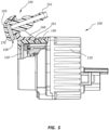
FIG. 5 is a partial, cross-sectional view of the vehicle camera assembly ofFIG. 1 with the cleaning assembly coupled to the vehicle camera; -
FIG. 6 is a partial, exploded, perspective view of a vehicle camera assembly comprising a cleaning assembly coupleable with a vehicle camera according to other unclaimed embodiments with the cleaning assembly shown being coupled with the vehicle camera unit; and -
FIG. 7 is a partial, perspective view of the embodiment ofFIG. 6 with the cleaning assembly shown coupled with the vehicle camera. - A detailed description of apparatus, systems, and methods consistent with various embodiments of the present disclosure is provided below.
- Apparatus, methods, and systems are disclosed herein relating to apparatus and systems for cleaning vehicle cameras, such as infrared vehicle cameras. In some embodiments, the inventive principles disclosed herein may be used to allow for a nozzle assembly to be easily snapped or otherwise locked in place, in some embodiments releasably locked in place, on a camera assembly and/or housing. In preferred embodiments, snap-fit engagement means, such as one or more flexible coupling members comprising one or more features for releasably locking the self-cleaning assembly with a vehicle camera housing in a snap-fit configuration, such as a hooked end portion, and/or one or more rigid coupling members that may be configured to be, for example, slidably engaged with the housing.
- The embodiments of the disclosure may be best understood by reference to the drawings, wherein like parts may be designated by like numerals. It will be readily understood that the components of the disclosed embodiments, as generally described and illustrated in the figures herein, could be arranged and designed in a wide variety of different configurations. Thus, the following detailed description of the embodiments of the apparatus and methods of the disclosure is not intended to limit the scope of the disclosure, as claimed, but is merely representative of possible embodiments of the disclosure. In addition, the steps of a method do not necessarily need to be executed in any specific order, or even sequentially, nor need the steps be executed only once, unless otherwise specified. Additional details regarding certain preferred embodiments and implementations will now be described in greater detail with reference to the accompanying drawings.
-
FIG. 1 is a perspective view of avehicle camera assembly 100.Vehicle camera assembly 100 comprises acamera housing 110.Camera housing 110 comprises alens housing 122 that projects from the main body ofhousing 110 and anexterior window 120, which may comprise a lens and/or may protect one or more lenses behindwindow 120. A fluidspray nozzle assembly 150 is coupled withhousing 110. Fluidspray nozzle assembly 150 is configured to spray a fluid 10 upon theexterior window 120 when the fluidspray nozzle assembly 150 is coupled with thehousing 110. - As explained below and best seen in subsequent figures, fluid
spray nozzle assembly 150 may comprise abody 165, which may comprise aflexible coupling member 160, which may be configured to provide for a releasable, snap-fit coupling withhousing 110. In the depicted embodiment,flexible coupling member 160 comprises a hooked end portion that may be configured to engage anengagement feature 130, such as a recess or ridge/protrusion formed onhousing 110. In addition, fluidspray nozzle assembly 150 comprises a pair ofrigid coupling members rigid coupling members housing 110. Couplingmembers 154/156 are preferably formed with mating features configured to engage corresponding mating features formed oncoupling members 124/126 to allow for a sliding engagement therebetween. In some embodiments, couplingmembers 154/156 may be configured to slidably nest within the corresponding mating features ofcoupling members 124/126. -
FIG. 2 is an exploded, perspective view ofvehicle camera assembly 100 with fluidspray nozzle assembly 150 shown decoupled fromhousing 110. As better seen in this figure,body 165 is angled with respect tohousing 110 andexterior window 120 to allow the cleaning fluid nozzle 158 (seeFIG. 5 ) to be directed back atexterior window 120.Port 152 is configured to be coupled with a cleaning fluid source to allow for delivery of the cleaning fluid ontoexterior window 120. - In addition,
FIG. 2 showsengagement feature 130 positioned in betweenrigid coupling members lens housing 122. Thus, upon insertingrigid coupling members 154/156 intorigid coupling members 124/126 and sliding fluidspray nozzle assembly 150 towardshousing 110,flexible coupling member 160 is configured to resiliently deform and then allowhooked end portion 161 to seat withengagement feature 130 to lock fluidspray nozzle assembly 150 ontohousing 110. Also,rigid coupling members 154/156 andflexible coupling member 160 are configured to allow a user to deformflexible coupling member 160 to allowhooked end portion 161 to disengage fromengagement feature 130 and, ultimately, to allow fluidspray nozzle assembly 150 to be removed fromhousing 110 if needed. -
Flexible coupling member 160, along withrigid coupling members 154/156,rigid coupling members 124/126, andengagement feature 130, such as a recess and/or ridge, is an example of means for locking, or releasably locking, a self-cleaning assembly with a camera housing.Flexible coupling member 160, along withrigid coupling members 154/156,rigid coupling members 124/126, andengagement feature 130 is also an example of flexible coupling snap-fit engagement means for locking, or releasably locking, a self-cleaning assembly with a housing in a snap-fit configuration. Moreover,flexible coupling member 160 is an example of a resiliently-deformable snap-fit engagement means. -
FIG. 3 is another exploded, perspective view ofvehicle camera assembly 100 with fluidspray nozzle assembly 150 shown decoupled fromhousing 110. As also shown in this figure, fluidspray nozzle assembly 150 may comprise a modular plurality of additional components that may be coupled with one another, in some embodiments also in a "snap-fit" configuration. As used herein, "snap fit" means a coupling between two elements formed by the shape of the elements so that the elements are attached by assembling them together. In deformable snap-fit configurations, the shape of the elements causes a deflection or deformation in either one or both of the elements and thereby causes the two elements to be held together. As previously mentioned, some embodiments/elements disclosed herein may further comprise detachable or decoupleable snap-fit configurations wherein the two elements may be separated from one another, such as by reversing the initial deformation. - As shown in
FIG. 3 , fluidspray nozzle assembly 150 may comprise abody 165 having acentral opening 167. Opening 167 may comprise one or more features configured to allow for an engagement, such as a snap-fit engagement, betweenbody 165 andnozzle piece 155. Thus, for example,nozzle piece 155 comprises a pair of opposingcoupling members 157A/157B. Preferably,coupling members 157A/157B comprise resiliently flexible coupling members that are configured to flex towards one another to fit throughopening 167 and then expand outwards to locknozzle piece 155 in place withinbody 165. One or more other features may further facilitate a desired coupling. For example, a raisedridge 159 may be formed on one or both sides ofnozzle piece 155. Corresponding slots may be formed inopening 167 to facilitate coupling ofnozzle piece 155 withbody 165 in a desired orientation. As also shown inFIG. 3 , aspray nozzle module 170 may be provided to allow for adjustment of the spray characteristics, such as the spray angle, distribution, force, and/or dispersion pattern. - The structure of
rigid coupling members FIG. 3 . For example, it can be seen thatcoupling members coupling members members -
FIG. 4 is an upper plan view ofvehicle camera assembly 100 after fluidspray nozzle assembly 150 has been coupled withhousing 110. AndFIG. 5 is a cross-sectional view taken along line 5 - 5 inFIG. 4 . As shown in the cross-sectional view, cleaningfluid nozzle 158 is fluidly coupled with the opening ofport 152 to allow for delivery of a cleaning fluid therethrough and ontoouter window 120. - As also best seen in
FIG. 5 , thehooked end portion 161 offlexible coupling member 160 is seated withinrecess 130 to lock fluidspray nozzle assembly 150 in place onto the upper surface ofhousing 110. In addition, although not depicted inFIG. 5 , as previously described, the opposingrigid coupling members spray nozzle assembly 150 andhousing 110. -
FIGS. 6 and 7 depict an alternative embodiment of avehicle camera assembly 200 also having a fluidspray nozzle assembly 250 that is configured to be quickly and easily coupled with acamera housing 210. As withvehicle camera assembly 100,vehicle camera assembly 200 comprises acamera housing 210 having a lens housing that projects from the main body ofhousing 210 and an exterior window, which may comprise a lens and/or may protect one or more lenses behind the window. Again, fluidspray nozzle assembly 250 is configured to spray a fluid upon the exterior window when the fluidspray nozzle assembly 250 is coupled with thehousing 210. - Fluid
spray nozzle assembly 250 again comprises abody 265.Body 265 may be configured to angle the spray nozzle ofassembly 250 so as to direct the cleaning fluid in a desirable manner towards the exterior window.Body 265 may also comprise one or more features configured to provide for a snap-fit coupling withhousing 210. In some embodiments, this may comprise a releasable coupling. - Unlike fluid
spray nozzle assembly 150, however, fluidspray nozzle assembly 250 only comprises a single,flexible coupling member 260 that is configured to engage a corresponding coupling member formed on the lens housing ofcamera housing 210. More particularly,coupling member 260 comprises an elongated, flexible prong having a hooked end portion similar tocoupling member 160. However,coupling member 260 comprises a keyed opening at its distal end that comprises ahorizontal slot 263 and avertical slot 262, both of which extend into arecess 264 formed withincoupling member 260. Theseslots 262/263 are configured to receive respective portions of the coupling member formed oncamera housing 210, which coupling member comprises aplate portion 226 configured to be received inhorizontal slot 263 and a bar orvertical portion 224 configured to be received withinvertical slot 262. - A
stop 230 or locking means may be provided, which may engage the hooked orpronged end portion 261 ofcoupling member 260 to secure the fluidspray nozzle assembly 250 in place onhousing 210. In the depicted embodiment, stop 230 is ramped so as to provide a means for automatically flexingcoupling member 260 during the snap-fit coupling process. - In addition,
body 265 of fluidspray nozzle assembly 250 comprises a pair of stabilizinglegs camera housing 210. As shown inFIG. 6 , both of these stabilizing members preferably comprise lower surfaces that are angled to match the curved surface of the lens housing ofcamera housing 210. In this manner, by moving the slotted opening ofcoupling member 260 towardsplate portion 226 andvertical portion 224, the feet or lower surfaces of stabilizinglegs housing 210 and slidably engage and guidecoupling member 260 over the rampedstop 230 to lock thespray nozzle assembly 250 in place. - Coupling
member 260, along with the corresponding coupling feature ofcamera housing 210, which is defined byplate portion 226 andvertical portion 224, is another example of means for locking, or releasably locking, a self-cleaning assembly with a camera housing.Flexible coupling member 260, along with the corresponding coupling feature ofcamera housing 210, which is defined byplate portion 226 andvertical portion 224, is also another example of flexible coupling snap-fit engagement means for locking, or releasably locking, a self-cleaning assembly with a housing in a snap-fit configuration. Moreover,flexible coupling member 260 is also another example of a resiliently-deformable snap-fit engagement means. Stabilizinglegs - Although not shown in as much detail in
FIGS. 6 and 7 , fluidspray nozzle assembly 250 may comprise various other features/components in common with fluidspray nozzle assembly 150. For example, fluidspray nozzle assembly 250 may comprise aport 252 configured to be fluidly coupled with a source of cleaning fluid. Fluidspray nozzle assembly 250 may further comprise abody 265 having a central opening configured to allow for an engagement, such as a snap-fit engagement, betweenbody 265 and aseparate nozzle piece 255 ofnozzle assembly 250. Thus, for example,nozzle piece 255 may again comprise a pair of opposingcoupling members 257A/257B, which may comprise resiliently flexible coupling members that are configured to flex towards one another to fit through the opening, similar toopening 167, formed innozzle body 265 and then expand outwards to locknozzle piece 255 in place withinbody 265. Other features, such as one or more raisedridges 259 may also be formed on one or both sides ofnozzle piece 255, which features may be configured to be received in corresponding slots or other features formed in the opening ofnozzle body 265, as previously described, to facilitate coupling ofnozzle piece 255 withbody 265 in a desired orientation. - The foregoing specification has been described with reference to various embodiments and implementations. However, one of ordinary skill in the art will appreciate that various modifications and changes can be made without departing from the scope of the present disclosure. For example, various operational steps, as well as components for carrying out operational steps, may be implemented in various ways depending upon the particular application or in consideration of any number of cost functions associated with the operation of the system. Accordingly, any one or more of the steps may be deleted, modified, or combined with other steps. Further, this disclosure is to be regarded in an illustrative rather than a restrictive sense, and all such modifications are intended to be included within the scope thereof. Likewise, benefits, other advantages, and solutions to problems have been described above with regard to various embodiments. However, benefits, advantages, solutions to problems, and any element(s) that may cause any benefit, advantage, or solution to occur or become more pronounced, are not to be construed as a critical, a required, or an essential feature or element.
- Those having skill in the art will appreciate that many changes may be made to the details of the above-described embodiments without departing from the underlying principles of the invention. The scope of the present inventions should, therefore, be determined only by the following claims.
Claims (6)
- A vehicle camera assembly (100),
comprising: a housing (110);a camera coupled with the housing (110);a self-cleaning assembly (150) releasably coupleable with the housing (110); and means for releasably locking the self-cleaning assembly with the housing (110),wherein the means for releasably locking the self-cleaning assembly (150) with the housing (110) comprises:a first pair of rigid coupling members formed on the self-cleaning assembly (150), anda second pair of rigid coupling members formed on the housing (110), wherein the first pair of rigid coupling members is configured to slidably engage the second pair of rigid coupling members,wherein the second pair of rigid coupling members protrudes from an exterior surface of the housing (110), characterized in that the means for releasably locking the self-cleaning assembly (150) with the housing (110) further comprises a flexible coupling member configured to resiliently engage at least one of a recess and a ridge formed on the housing (110), wherein the at least one of a recess and a ridge is formed in the exterior surface of the housing (110) in between the second pair of rigid coupling members. - The vehicle camera assembly (100) of claim 1, wherein the means for releasably locking the self-cleaning assembly (150) with the housing (110) comprises snap-fit engagement means for releasably locking the self-cleaning assembly (150) with the housing in a snap-fit configuration.
- The vehicle camera assembly (100) of claim 2, wherein the snap-fit engagement means comprises a resiliently-deformable snap-fit engagement means.
- The vehicle camera assembly (100) of claim 3, wherein the resiliently-deformable snap-fit engagement means comprises the flexible coupling member and preferably wherein the flexible coupling member extends from the self-cleaning assembly (150).
- The vehicle camera assembly (100) of claim 1, wherein the flexible coupling member comprises a hooked end portion configured to releasably engage the at least one of a recess and a ridge.
- A cleaning assembly (150) for coupling with a vehicle camera,
comprising: a body (165);a nozzle coupled with the body (165), wherein the nozzle is configured to deliver a fluid therethrough to clean an exterior window of a vehicle camera upon coupling the cleaning assembly with the vehicle camera;a pair of rigid coupling members configured to engage a vehicle camera housing to allow the cleaning assembly to be coupled with the vehicle camera; characterized in that the cleaning assembly further comprisesa flexible coupling member configured to engage the vehicle camera housing,wherein the flexible coupling member comprises a hooked end portion, wherein the hooked end portion is configured to resiliently engage an engagement feature formed on the vehicle camera housing and wherein the flexible coupling member extends from the body (165) in between the pair of rigid coupling members.
Applications Claiming Priority (2)
| Application Number | Priority Date | Filing Date | Title |
|---|---|---|---|
| US15/828,203 US10409055B2 (en) | 2017-11-30 | 2017-11-30 | Self-cleaning vehicle camera assemblies |
| PCT/US2018/062928 WO2019108710A1 (en) | 2017-11-30 | 2018-11-28 | Self-cleaning vehicle camera assemblies |
Publications (3)
| Publication Number | Publication Date |
|---|---|
| EP3717953A1 EP3717953A1 (en) | 2020-10-07 |
| EP3717953A4 EP3717953A4 (en) | 2021-08-04 |
| EP3717953B1 true EP3717953B1 (en) | 2023-03-01 |
Family
ID=66632301
Family Applications (1)
| Application Number | Title | Priority Date | Filing Date |
|---|---|---|---|
| EP18883923.7A Active EP3717953B1 (en) | 2017-11-30 | 2018-11-28 | Self-cleaning vehicle camera assemblies |
Country Status (4)
| Country | Link |
|---|---|
| US (1) | US10409055B2 (en) |
| EP (1) | EP3717953B1 (en) |
| CN (1) | CN111344625A (en) |
| WO (1) | WO2019108710A1 (en) |
Families Citing this family (13)
| Publication number | Priority date | Publication date | Assignee | Title |
|---|---|---|---|---|
| US10549723B2 (en) * | 2018-05-04 | 2020-02-04 | Ford Global Technologies, Llc | Vehicle object-detection sensor assembly |
| US11279325B2 (en) * | 2019-06-24 | 2022-03-22 | Ford Global Technologies, Llc | Sensor cleaning |
| US11478827B2 (en) * | 2019-10-01 | 2022-10-25 | Ford Global Technologies, Llc | Sensor assembly with cleaning |
| US10802121B1 (en) * | 2019-10-09 | 2020-10-13 | Ford Global Technologies, Llc | Cleaning apparatus for sensor |
| KR102260813B1 (en) * | 2019-11-14 | 2021-06-07 | 주식회사 니프코코리아 | Automotive Composite Nozzle |
| US12269436B2 (en) * | 2020-07-09 | 2025-04-08 | A. Raymond Et Cie | Bracket and modular assembly for fluid spray system |
| USD1051009S1 (en) * | 2022-02-18 | 2024-11-12 | Autel Robotics Co., Ltd. | Camera with gimbal |
| FR3139777B1 (en) * | 2022-09-21 | 2025-12-26 | Valeo Systemes Dessuyage | Cleaning device assembled with a support |
| FR3142147A1 (en) * | 2022-11-22 | 2024-05-24 | Valeo Systèmes D’Essuyage | Support for cleaning nozzle of a sensor for a motor vehicle |
| GB2622901B (en) * | 2023-02-17 | 2025-06-18 | Wartsila Guidance Marine Ltd | Camera washer assembly and device |
| USD1069879S1 (en) * | 2023-02-27 | 2025-04-08 | e-con Systems India Private Limited | Camera enclosure |
| USD1108528S1 (en) * | 2024-06-27 | 2026-01-06 | Amphenol Corporation | Camera housing assembly |
| KR102855489B1 (en) * | 2025-02-27 | 2025-09-04 | 디와이오토 주식회사 | Cleaning device for vehicle sensor camera lens |
Family Cites Families (23)
| Publication number | Priority date | Publication date | Assignee | Title |
|---|---|---|---|---|
| JP2001171491A (en) | 1999-12-16 | 2001-06-26 | Matsushita Electric Ind Co Ltd | Vehicle-mounted camera device and method of cleaning vehicle-mounted camera |
| JP2004182080A (en) | 2002-12-03 | 2004-07-02 | Mitsubishi Electric Corp | Vehicle with infrared camera and infrared camera system |
| JP2007053448A (en) | 2005-08-15 | 2007-03-01 | Fujifilm Corp | Imaging device |
| JP4513889B2 (en) | 2008-04-03 | 2010-07-28 | 株式会社日本自動車部品総合研究所 | Camera with washer nozzle and washer nozzle |
| WO2014010579A1 (en) | 2012-07-11 | 2014-01-16 | 日産自動車株式会社 | Vehicle-mounted-camera cleaning device |
| JP6090319B2 (en) | 2012-07-11 | 2017-03-08 | 日産自動車株式会社 | In-vehicle camera cleaning device |
| BR112015000243B1 (en) | 2012-07-11 | 2021-07-13 | Nissan Motor Co., Ltd | CLEANING DEVICE FOR VEHICLE MOUNTED CAMERA AND METHOD OF CLEANING VEHICLE MOUNTED CAMERA |
| US10616491B2 (en) * | 2013-02-01 | 2020-04-07 | Deka Products Limited Partnership | Endoscope with pannable camera and related method |
| US9126534B2 (en) | 2013-03-14 | 2015-09-08 | Ford Global Technologies, Llc | Automated camera wash for vehicles |
| JP6379665B2 (en) * | 2013-08-12 | 2018-08-29 | 株式会社デンソー | In-vehicle optical sensor cleaning device |
| DE102014202072A1 (en) | 2014-01-24 | 2015-07-30 | Bayerische Motoren Werke Aktiengesellschaft | Device for cleaning an optical lens of a parking assistance camera |
| EP3105089B1 (en) * | 2014-02-14 | 2018-03-14 | Kautex Textron GmbH & Co. KG. | Air and fluid cleaning system and method for cleaning vehicle vision devices |
| EP2949521B1 (en) * | 2014-05-27 | 2019-07-24 | Fico Transpar, S.A. | Cleaning device and system for vehicle-mounted optic surface and vehicle-mounted optic sensor with cleaning device |
| US10059280B2 (en) * | 2014-06-06 | 2018-08-28 | Joseph Richard Cooper | Obstruction-removal system and method for vehicle-camera lens |
| DE102014117165A1 (en) | 2014-11-24 | 2016-05-25 | Kautex Textron Gmbh & Co. Kg | Vehicle integrated vision and cleaning system |
| WO2016105674A1 (en) * | 2014-12-22 | 2016-06-30 | Illinois Tool Works Inc. | Dual plane heater for vehicle sensor system |
| US20160272163A1 (en) * | 2015-03-17 | 2016-09-22 | Magna Electronics Inc. | Vehicle camera with lens washer system |
| US10035498B2 (en) | 2015-04-22 | 2018-07-31 | Ford Global Technologies, Llc | Vehicle camera cleaning system |
| JP6547948B2 (en) * | 2015-07-07 | 2019-07-24 | ミツミ電機株式会社 | Foreign object adhesion preventing device and camera device provided with the same |
| FR3039114B1 (en) * | 2015-07-22 | 2017-07-28 | Valeo Systemes Dessuyage | DEVICE FOR CLEANING A SENSOR FOR A MOTOR VEHICLE |
| FR3040944B1 (en) * | 2015-09-14 | 2017-09-08 | Valeo Systemes Dessuyage | SYSTEM AND METHOD FOR WIPING A VEHICLE GLASS |
| JP6855216B2 (en) * | 2016-11-04 | 2021-04-07 | 株式会社デンソーテン | Optical unit and how to attach the optical unit |
| DE102017101641B4 (en) * | 2017-01-27 | 2021-10-21 | SMR Patents S.à.r.l. | Wiper device for optical device with lens and rearview device for motor vehicle with such a wiper device |
-
2017
- 2017-11-30 US US15/828,203 patent/US10409055B2/en active Active
-
2018
- 2018-11-28 WO PCT/US2018/062928 patent/WO2019108710A1/en not_active Ceased
- 2018-11-28 EP EP18883923.7A patent/EP3717953B1/en active Active
- 2018-11-28 CN CN201880072852.8A patent/CN111344625A/en active Pending
Also Published As
| Publication number | Publication date |
|---|---|
| US10409055B2 (en) | 2019-09-10 |
| EP3717953A1 (en) | 2020-10-07 |
| EP3717953A4 (en) | 2021-08-04 |
| WO2019108710A1 (en) | 2019-06-06 |
| US20190162951A1 (en) | 2019-05-30 |
| CN111344625A (en) | 2020-06-26 |
Similar Documents
| Publication | Publication Date | Title |
|---|---|---|
| EP3717953B1 (en) | Self-cleaning vehicle camera assemblies | |
| JP6722279B2 (en) | Cleaning device for cleaning the transparent cover of the camera | |
| EP3131797B1 (en) | Integrated automotive system, compact, low-profile nozzle assembly and compact fluidic circuit for cleaning a wide-angle image sensor's exterior surface | |
| KR102065792B1 (en) | Quick connector coupling | |
| US10525937B2 (en) | Integrated multi image sensor and lens washing nozzle assembly and method for simultaneously cleaning a plurality of image sensors | |
| US20200061643A1 (en) | Dual media nozzle | |
| US11491918B2 (en) | Sensor module for a vehicle including at least one sensor | |
| CN109312765B (en) | Flow control system, jumper hose element, and fluid flow management method | |
| US12269436B2 (en) | Bracket and modular assembly for fluid spray system | |
| CN105499183A (en) | Device for cleaning motor vehicle driving aid camera | |
| CN108778859A (en) | Device for the Systems for optical inspection for cleaning motor vehicles | |
| US12303920B2 (en) | Fluid spray nozzle for cleaning device for an optical detection system | |
| JP2019038522A (en) | Optical sensor support plate, delivery body of telescopic cleaning device of this optical sensor, and quick fixing device by clipping these components | |
| CN113613951B (en) | Camera device for vehicle | |
| US20180091779A1 (en) | Imager with wire harness connecting features | |
| US12092894B2 (en) | Arrangement for mounting an optical system on a body element of a vehicle | |
| CN110871773B (en) | Cleaning system for vehicle | |
| US10518752B2 (en) | Washing fluid spray device for a wiper arm for a system for wiping a window of a motor vehicle | |
| US20240181997A1 (en) | Camera nozzle assembly | |
| US12282246B2 (en) | Camera module configured to interact with a fastening holder | |
| CN117015489A (en) | Device for cleaning surfaces by means of movable deflected jets |
Legal Events
| Date | Code | Title | Description |
|---|---|---|---|
| STAA | Information on the status of an ep patent application or granted ep patent |
Free format text: STATUS: THE INTERNATIONAL PUBLICATION HAS BEEN MADE |
|
| PUAI | Public reference made under article 153(3) epc to a published international application that has entered the european phase |
Free format text: ORIGINAL CODE: 0009012 |
|
| STAA | Information on the status of an ep patent application or granted ep patent |
Free format text: STATUS: REQUEST FOR EXAMINATION WAS MADE |
|
| 17P | Request for examination filed |
Effective date: 20200324 |
|
| AK | Designated contracting states |
Kind code of ref document: A1 Designated state(s): AL AT BE BG CH CY CZ DE DK EE ES FI FR GB GR HR HU IE IS IT LI LT LU LV MC MK MT NL NO PL PT RO RS SE SI SK SM TR |
|
| AX | Request for extension of the european patent |
Extension state: BA ME |
|
| DAV | Request for validation of the european patent (deleted) | ||
| DAX | Request for extension of the european patent (deleted) | ||
| A4 | Supplementary search report drawn up and despatched |
Effective date: 20210707 |
|
| RIC1 | Information provided on ipc code assigned before grant |
Ipc: G02B 27/00 20060101AFI20210701BHEP Ipc: B60S 1/48 20060101ALI20210701BHEP Ipc: B60S 1/52 20060101ALI20210701BHEP Ipc: B60R 1/06 20060101ALI20210701BHEP |
|
| RAP3 | Party data changed (applicant data changed or rights of an application transferred) |
Owner name: VEONEER US, LLC |
|
| RAP3 | Party data changed (applicant data changed or rights of an application transferred) |
Owner name: VEONEER US, LLC |
|
| GRAP | Despatch of communication of intention to grant a patent |
Free format text: ORIGINAL CODE: EPIDOSNIGR1 |
|
| STAA | Information on the status of an ep patent application or granted ep patent |
Free format text: STATUS: GRANT OF PATENT IS INTENDED |
|
| INTG | Intention to grant announced |
Effective date: 20221115 |
|
| GRAS | Grant fee paid |
Free format text: ORIGINAL CODE: EPIDOSNIGR3 |
|
| GRAA | (expected) grant |
Free format text: ORIGINAL CODE: 0009210 |
|
| STAA | Information on the status of an ep patent application or granted ep patent |
Free format text: STATUS: THE PATENT HAS BEEN GRANTED |
|
| AK | Designated contracting states |
Kind code of ref document: B1 Designated state(s): AL AT BE BG CH CY CZ DE DK EE ES FI FR GB GR HR HU IE IS IT LI LT LU LV MC MK MT NL NO PL PT RO RS SE SI SK SM TR |
|
| REG | Reference to a national code |
Ref country code: GB Ref legal event code: FG4D |
|
| REG | Reference to a national code |
Ref country code: CH Ref legal event code: EP Ref country code: AT Ref legal event code: REF Ref document number: 1551390 Country of ref document: AT Kind code of ref document: T Effective date: 20230315 |
|
| REG | Reference to a national code |
Ref country code: DE Ref legal event code: R096 Ref document number: 602018046813 Country of ref document: DE |
|
| REG | Reference to a national code |
Ref country code: IE Ref legal event code: FG4D |
|
| REG | Reference to a national code |
Ref country code: SE Ref legal event code: TRGR |
|
| P01 | Opt-out of the competence of the unified patent court (upc) registered |
Effective date: 20230508 |
|
| REG | Reference to a national code |
Ref country code: LT Ref legal event code: MG9D |
|
| REG | Reference to a national code |
Ref country code: NL Ref legal event code: MP Effective date: 20230301 |
|
| PG25 | Lapsed in a contracting state [announced via postgrant information from national office to epo] |
Ref country code: RS Free format text: LAPSE BECAUSE OF FAILURE TO SUBMIT A TRANSLATION OF THE DESCRIPTION OR TO PAY THE FEE WITHIN THE PRESCRIBED TIME-LIMIT Effective date: 20230301 Ref country code: NO Free format text: LAPSE BECAUSE OF FAILURE TO SUBMIT A TRANSLATION OF THE DESCRIPTION OR TO PAY THE FEE WITHIN THE PRESCRIBED TIME-LIMIT Effective date: 20230601 Ref country code: LV Free format text: LAPSE BECAUSE OF FAILURE TO SUBMIT A TRANSLATION OF THE DESCRIPTION OR TO PAY THE FEE WITHIN THE PRESCRIBED TIME-LIMIT Effective date: 20230301 Ref country code: LT Free format text: LAPSE BECAUSE OF FAILURE TO SUBMIT A TRANSLATION OF THE DESCRIPTION OR TO PAY THE FEE WITHIN THE PRESCRIBED TIME-LIMIT Effective date: 20230301 Ref country code: HR Free format text: LAPSE BECAUSE OF FAILURE TO SUBMIT A TRANSLATION OF THE DESCRIPTION OR TO PAY THE FEE WITHIN THE PRESCRIBED TIME-LIMIT Effective date: 20230301 Ref country code: ES Free format text: LAPSE BECAUSE OF FAILURE TO SUBMIT A TRANSLATION OF THE DESCRIPTION OR TO PAY THE FEE WITHIN THE PRESCRIBED TIME-LIMIT Effective date: 20230301 |
|
| REG | Reference to a national code |
Ref country code: AT Ref legal event code: MK05 Ref document number: 1551390 Country of ref document: AT Kind code of ref document: T Effective date: 20230301 |
|
| PG25 | Lapsed in a contracting state [announced via postgrant information from national office to epo] |
Ref country code: PL Free format text: LAPSE BECAUSE OF FAILURE TO SUBMIT A TRANSLATION OF THE DESCRIPTION OR TO PAY THE FEE WITHIN THE PRESCRIBED TIME-LIMIT Effective date: 20230301 Ref country code: NL Free format text: LAPSE BECAUSE OF FAILURE TO SUBMIT A TRANSLATION OF THE DESCRIPTION OR TO PAY THE FEE WITHIN THE PRESCRIBED TIME-LIMIT Effective date: 20230301 Ref country code: GR Free format text: LAPSE BECAUSE OF FAILURE TO SUBMIT A TRANSLATION OF THE DESCRIPTION OR TO PAY THE FEE WITHIN THE PRESCRIBED TIME-LIMIT Effective date: 20230602 Ref country code: FI Free format text: LAPSE BECAUSE OF FAILURE TO SUBMIT A TRANSLATION OF THE DESCRIPTION OR TO PAY THE FEE WITHIN THE PRESCRIBED TIME-LIMIT Effective date: 20230301 |
|
| PG25 | Lapsed in a contracting state [announced via postgrant information from national office to epo] |
Ref country code: SM Free format text: LAPSE BECAUSE OF FAILURE TO SUBMIT A TRANSLATION OF THE DESCRIPTION OR TO PAY THE FEE WITHIN THE PRESCRIBED TIME-LIMIT Effective date: 20230301 Ref country code: RO Free format text: LAPSE BECAUSE OF FAILURE TO SUBMIT A TRANSLATION OF THE DESCRIPTION OR TO PAY THE FEE WITHIN THE PRESCRIBED TIME-LIMIT Effective date: 20230301 Ref country code: PT Free format text: LAPSE BECAUSE OF FAILURE TO SUBMIT A TRANSLATION OF THE DESCRIPTION OR TO PAY THE FEE WITHIN THE PRESCRIBED TIME-LIMIT Effective date: 20230703 Ref country code: EE Free format text: LAPSE BECAUSE OF FAILURE TO SUBMIT A TRANSLATION OF THE DESCRIPTION OR TO PAY THE FEE WITHIN THE PRESCRIBED TIME-LIMIT Effective date: 20230301 Ref country code: CZ Free format text: LAPSE BECAUSE OF FAILURE TO SUBMIT A TRANSLATION OF THE DESCRIPTION OR TO PAY THE FEE WITHIN THE PRESCRIBED TIME-LIMIT Effective date: 20230301 Ref country code: AT Free format text: LAPSE BECAUSE OF FAILURE TO SUBMIT A TRANSLATION OF THE DESCRIPTION OR TO PAY THE FEE WITHIN THE PRESCRIBED TIME-LIMIT Effective date: 20230301 |
|
| PG25 | Lapsed in a contracting state [announced via postgrant information from national office to epo] |
Ref country code: SK Free format text: LAPSE BECAUSE OF FAILURE TO SUBMIT A TRANSLATION OF THE DESCRIPTION OR TO PAY THE FEE WITHIN THE PRESCRIBED TIME-LIMIT Effective date: 20230301 Ref country code: IS Free format text: LAPSE BECAUSE OF FAILURE TO SUBMIT A TRANSLATION OF THE DESCRIPTION OR TO PAY THE FEE WITHIN THE PRESCRIBED TIME-LIMIT Effective date: 20230701 |
|
| REG | Reference to a national code |
Ref country code: DE Ref legal event code: R097 Ref document number: 602018046813 Country of ref document: DE |
|
| PLBE | No opposition filed within time limit |
Free format text: ORIGINAL CODE: 0009261 |
|
| STAA | Information on the status of an ep patent application or granted ep patent |
Free format text: STATUS: NO OPPOSITION FILED WITHIN TIME LIMIT |
|
| PG25 | Lapsed in a contracting state [announced via postgrant information from national office to epo] |
Ref country code: SI Free format text: LAPSE BECAUSE OF FAILURE TO SUBMIT A TRANSLATION OF THE DESCRIPTION OR TO PAY THE FEE WITHIN THE PRESCRIBED TIME-LIMIT Effective date: 20230301 Ref country code: DK Free format text: LAPSE BECAUSE OF FAILURE TO SUBMIT A TRANSLATION OF THE DESCRIPTION OR TO PAY THE FEE WITHIN THE PRESCRIBED TIME-LIMIT Effective date: 20230301 |
|
| 26N | No opposition filed |
Effective date: 20231204 |
|
| REG | Reference to a national code |
Ref country code: DE Ref legal event code: R082 Ref document number: 602018046813 Country of ref document: DE Representative=s name: MEWBURN ELLIS LLP, DE Ref country code: DE Ref legal event code: R081 Ref document number: 602018046813 Country of ref document: DE Owner name: MAGNA ELECTRONICS, LLC (N.D.GES.D. STAATES DEL, US Free format text: FORMER OWNER: VEONEER US, LLC, SOUTHFIELD, MI, US |
|
| PG25 | Lapsed in a contracting state [announced via postgrant information from national office to epo] |
Ref country code: IT Free format text: LAPSE BECAUSE OF FAILURE TO SUBMIT A TRANSLATION OF THE DESCRIPTION OR TO PAY THE FEE WITHIN THE PRESCRIBED TIME-LIMIT Effective date: 20230301 |
|
| REG | Reference to a national code |
Ref country code: CH Ref legal event code: PL |
|
| PG25 | Lapsed in a contracting state [announced via postgrant information from national office to epo] |
Ref country code: MC Free format text: LAPSE BECAUSE OF FAILURE TO SUBMIT A TRANSLATION OF THE DESCRIPTION OR TO PAY THE FEE WITHIN THE PRESCRIBED TIME-LIMIT Effective date: 20230301 |
|
| PG25 | Lapsed in a contracting state [announced via postgrant information from national office to epo] |
Ref country code: LU Free format text: LAPSE BECAUSE OF NON-PAYMENT OF DUE FEES Effective date: 20231128 |
|
| PG25 | Lapsed in a contracting state [announced via postgrant information from national office to epo] |
Ref country code: CH Free format text: LAPSE BECAUSE OF NON-PAYMENT OF DUE FEES Effective date: 20231130 |
|
| PG25 | Lapsed in a contracting state [announced via postgrant information from national office to epo] |
Ref country code: MC Free format text: LAPSE BECAUSE OF FAILURE TO SUBMIT A TRANSLATION OF THE DESCRIPTION OR TO PAY THE FEE WITHIN THE PRESCRIBED TIME-LIMIT Effective date: 20230301 Ref country code: LU Free format text: LAPSE BECAUSE OF NON-PAYMENT OF DUE FEES Effective date: 20231128 Ref country code: CH Free format text: LAPSE BECAUSE OF NON-PAYMENT OF DUE FEES Effective date: 20231130 |
|
| REG | Reference to a national code |
Ref country code: BE Ref legal event code: MM Effective date: 20231130 |
|
| REG | Reference to a national code |
Ref country code: IE Ref legal event code: MM4A |
|
| PG25 | Lapsed in a contracting state [announced via postgrant information from national office to epo] |
Ref country code: IE Free format text: LAPSE BECAUSE OF NON-PAYMENT OF DUE FEES Effective date: 20231128 |
|
| PG25 | Lapsed in a contracting state [announced via postgrant information from national office to epo] |
Ref country code: BE Free format text: LAPSE BECAUSE OF NON-PAYMENT OF DUE FEES Effective date: 20231130 |
|
| PG25 | Lapsed in a contracting state [announced via postgrant information from national office to epo] |
Ref country code: IE Free format text: LAPSE BECAUSE OF NON-PAYMENT OF DUE FEES Effective date: 20231128 Ref country code: BE Free format text: LAPSE BECAUSE OF NON-PAYMENT OF DUE FEES Effective date: 20231130 |
|
| PG25 | Lapsed in a contracting state [announced via postgrant information from national office to epo] |
Ref country code: BG Free format text: LAPSE BECAUSE OF FAILURE TO SUBMIT A TRANSLATION OF THE DESCRIPTION OR TO PAY THE FEE WITHIN THE PRESCRIBED TIME-LIMIT Effective date: 20230301 |
|
| PG25 | Lapsed in a contracting state [announced via postgrant information from national office to epo] |
Ref country code: BG Free format text: LAPSE BECAUSE OF FAILURE TO SUBMIT A TRANSLATION OF THE DESCRIPTION OR TO PAY THE FEE WITHIN THE PRESCRIBED TIME-LIMIT Effective date: 20230301 |
|
| PGFP | Annual fee paid to national office [announced via postgrant information from national office to epo] |
Ref country code: GB Payment date: 20241120 Year of fee payment: 7 |
|
| PGFP | Annual fee paid to national office [announced via postgrant information from national office to epo] |
Ref country code: SE Payment date: 20241120 Year of fee payment: 7 |
|
| PG25 | Lapsed in a contracting state [announced via postgrant information from national office to epo] |
Ref country code: CY Free format text: LAPSE BECAUSE OF FAILURE TO SUBMIT A TRANSLATION OF THE DESCRIPTION OR TO PAY THE FEE WITHIN THE PRESCRIBED TIME-LIMIT; INVALID AB INITIO Effective date: 20181128 |
|
| PG25 | Lapsed in a contracting state [announced via postgrant information from national office to epo] |
Ref country code: HU Free format text: LAPSE BECAUSE OF FAILURE TO SUBMIT A TRANSLATION OF THE DESCRIPTION OR TO PAY THE FEE WITHIN THE PRESCRIBED TIME-LIMIT; INVALID AB INITIO Effective date: 20181128 |
|
| PG25 | Lapsed in a contracting state [announced via postgrant information from national office to epo] |
Ref country code: TR Free format text: LAPSE BECAUSE OF FAILURE TO SUBMIT A TRANSLATION OF THE DESCRIPTION OR TO PAY THE FEE WITHIN THE PRESCRIBED TIME-LIMIT Effective date: 20230301 |
|
| PGFP | Annual fee paid to national office [announced via postgrant information from national office to epo] |
Ref country code: DE Payment date: 20251118 Year of fee payment: 8 |
|
| PGFP | Annual fee paid to national office [announced via postgrant information from national office to epo] |
Ref country code: FR Payment date: 20251125 Year of fee payment: 8 |