EP3717820B1 - Elekrtisch isoliertes rohrsystem mit einstellbarer länge - Google Patents
Elekrtisch isoliertes rohrsystem mit einstellbarer länge Download PDFInfo
- Publication number
- EP3717820B1 EP3717820B1 EP18826797.5A EP18826797A EP3717820B1 EP 3717820 B1 EP3717820 B1 EP 3717820B1 EP 18826797 A EP18826797 A EP 18826797A EP 3717820 B1 EP3717820 B1 EP 3717820B1
- Authority
- EP
- European Patent Office
- Prior art keywords
- pipe
- pipe system
- sections
- pipe sections
- electrically insulating
- Prior art date
- Legal status (The legal status is an assumption and is not a legal conclusion. Google has not performed a legal analysis and makes no representation as to the accuracy of the status listed.)
- Active
Links
Images

Classifications
-
- F—MECHANICAL ENGINEERING; LIGHTING; HEATING; WEAPONS; BLASTING
- F16—ENGINEERING ELEMENTS AND UNITS; GENERAL MEASURES FOR PRODUCING AND MAINTAINING EFFECTIVE FUNCTIONING OF MACHINES OR INSTALLATIONS; THERMAL INSULATION IN GENERAL
- F16L—PIPES; JOINTS OR FITTINGS FOR PIPES; SUPPORTS FOR PIPES, CABLES OR PROTECTIVE TUBING; MEANS FOR THERMAL INSULATION IN GENERAL
- F16L25/00—Construction or details of pipe joints not provided for in, or of interest apart from, groups F16L13/00 - F16L23/00
- F16L25/04—Construction or details of pipe joints not provided for in, or of interest apart from, groups F16L13/00 - F16L23/00 comprising a collar or ring having a threaded pin rigid with the pipe-encircling member
-
- F—MECHANICAL ENGINEERING; LIGHTING; HEATING; WEAPONS; BLASTING
- F16—ENGINEERING ELEMENTS AND UNITS; GENERAL MEASURES FOR PRODUCING AND MAINTAINING EFFECTIVE FUNCTIONING OF MACHINES OR INSTALLATIONS; THERMAL INSULATION IN GENERAL
- F16L—PIPES; JOINTS OR FITTINGS FOR PIPES; SUPPORTS FOR PIPES, CABLES OR PROTECTIVE TUBING; MEANS FOR THERMAL INSULATION IN GENERAL
- F16L58/00—Protection of pipes or pipe fittings against corrosion or incrustation
- F16L58/18—Protection of pipes or pipe fittings against corrosion or incrustation specially adapted for pipe fittings
- F16L58/185—Protection of pipes or pipe fittings against corrosion or incrustation specially adapted for pipe fittings for joints with sleeve or socket
-
- F—MECHANICAL ENGINEERING; LIGHTING; HEATING; WEAPONS; BLASTING
- F16—ENGINEERING ELEMENTS AND UNITS; GENERAL MEASURES FOR PRODUCING AND MAINTAINING EFFECTIVE FUNCTIONING OF MACHINES OR INSTALLATIONS; THERMAL INSULATION IN GENERAL
- F16L—PIPES; JOINTS OR FITTINGS FOR PIPES; SUPPORTS FOR PIPES, CABLES OR PROTECTIVE TUBING; MEANS FOR THERMAL INSULATION IN GENERAL
- F16L21/00—Joints with sleeve or socket
- F16L21/02—Joints with sleeve or socket with elastic sealing rings between pipe and sleeve or between pipe and socket, e.g. with rolling or other prefabricated profiled rings
- F16L21/03—Joints with sleeve or socket with elastic sealing rings between pipe and sleeve or between pipe and socket, e.g. with rolling or other prefabricated profiled rings placed in the socket before connection
-
- F—MECHANICAL ENGINEERING; LIGHTING; HEATING; WEAPONS; BLASTING
- F16—ENGINEERING ELEMENTS AND UNITS; GENERAL MEASURES FOR PRODUCING AND MAINTAINING EFFECTIVE FUNCTIONING OF MACHINES OR INSTALLATIONS; THERMAL INSULATION IN GENERAL
- F16L—PIPES; JOINTS OR FITTINGS FOR PIPES; SUPPORTS FOR PIPES, CABLES OR PROTECTIVE TUBING; MEANS FOR THERMAL INSULATION IN GENERAL
- F16L21/00—Joints with sleeve or socket
- F16L21/06—Joints with sleeve or socket with a divided sleeve or ring clamping around the pipe ends
- F16L21/065—Joints with sleeve or socket with a divided sleeve or ring clamping around the pipe ends tightened by tangentially-arranged threaded pins
-
- F—MECHANICAL ENGINEERING; LIGHTING; HEATING; WEAPONS; BLASTING
- F16—ENGINEERING ELEMENTS AND UNITS; GENERAL MEASURES FOR PRODUCING AND MAINTAINING EFFECTIVE FUNCTIONING OF MACHINES OR INSTALLATIONS; THERMAL INSULATION IN GENERAL
- F16L—PIPES; JOINTS OR FITTINGS FOR PIPES; SUPPORTS FOR PIPES, CABLES OR PROTECTIVE TUBING; MEANS FOR THERMAL INSULATION IN GENERAL
- F16L21/00—Joints with sleeve or socket
- F16L21/08—Joints with sleeve or socket with additional locking means
-
- F—MECHANICAL ENGINEERING; LIGHTING; HEATING; WEAPONS; BLASTING
- F16—ENGINEERING ELEMENTS AND UNITS; GENERAL MEASURES FOR PRODUCING AND MAINTAINING EFFECTIVE FUNCTIONING OF MACHINES OR INSTALLATIONS; THERMAL INSULATION IN GENERAL
- F16L—PIPES; JOINTS OR FITTINGS FOR PIPES; SUPPORTS FOR PIPES, CABLES OR PROTECTIVE TUBING; MEANS FOR THERMAL INSULATION IN GENERAL
- F16L27/00—Adjustable joints; Joints allowing movement
- F16L27/12—Adjustable joints; Joints allowing movement allowing substantial longitudinal adjustment or movement
- F16L27/127—Adjustable joints; Joints allowing movement allowing substantial longitudinal adjustment or movement with means for locking the longitudinal adjustment or movement in the final mounted position
- F16L27/1273—Adjustable joints; Joints allowing movement allowing substantial longitudinal adjustment or movement with means for locking the longitudinal adjustment or movement in the final mounted position by quick-acting means
-
- F—MECHANICAL ENGINEERING; LIGHTING; HEATING; WEAPONS; BLASTING
- F16—ENGINEERING ELEMENTS AND UNITS; GENERAL MEASURES FOR PRODUCING AND MAINTAINING EFFECTIVE FUNCTIONING OF MACHINES OR INSTALLATIONS; THERMAL INSULATION IN GENERAL
- F16L—PIPES; JOINTS OR FITTINGS FOR PIPES; SUPPORTS FOR PIPES, CABLES OR PROTECTIVE TUBING; MEANS FOR THERMAL INSULATION IN GENERAL
- F16L27/00—Adjustable joints; Joints allowing movement
- F16L27/12—Adjustable joints; Joints allowing movement allowing substantial longitudinal adjustment or movement
- F16L27/127—Adjustable joints; Joints allowing movement allowing substantial longitudinal adjustment or movement with means for locking the longitudinal adjustment or movement in the final mounted position
- F16L27/1275—Adjustable joints; Joints allowing movement allowing substantial longitudinal adjustment or movement with means for locking the longitudinal adjustment or movement in the final mounted position by means of at least an external threaded bolt
- F16L27/12751—Adjustable joints; Joints allowing movement allowing substantial longitudinal adjustment or movement with means for locking the longitudinal adjustment or movement in the final mounted position by means of at least an external threaded bolt the threaded bolt extending longitudinally
Definitions
- the present invention relates generally to pipe couplings, and particularly to an anti-corrosion pipe system with adjustable length.
- Pipes made of metal, such as cast iron, ductile iron or steel alloys, which are laid in the ground near sources of direct electrical current, such as near electrical railways, are prone to corrosion problems caused by stray current.
- the stray current can reach the buried pipes, entering at one point along the pipe path and exiting at a different point spaced longitudinally from the entry point.
- a partial cathodic reaction takes place; at the exit point, an anodic partial reaction occurs.
- the result is corrosion of metal all along the longitudinal path between entry and exit. The problem is particularly great in water pipes.
- Anti-corrosion coatings have been used on pipes to help prevent or reduce corrosion.
- seals that provide electrical resistance have been used between pipe sections to limit the length of the longitudinal path.
- the pipe sections must be welded or otherwise connected on site, and this work often involves guesswork and rework which causes time delays and increases labor costs.
- US 1 983 228 A discloses means for opposing loss of metal by electrolytic corrosion of the bolts and nuts of pipe joints which comprise metallic extensions longer than the exposed portions of the bolts and nuts and housing and covering the bolts and nuts and providing surface exposure by which current leaves the joints instead of leaving from the surface of the bolts and nuts.
- EP 2 392 845 A1 discloses an annular sealing material sealing a pipe joint between a socket and a spigot.
- the sealing material includes a bulb part which is composed of a first bulb, a second bulb located closer to the inner side of the socket than the first bulb, and a narrow part present between the first and second bulbs.
- the first bulb is pressed against the inner circumferential surface of the socket.
- the second bulb is pressed against the outer peripheral surface of the spigot.
- the second bulb is inclined towards the pipe center from the first bulb in a natural state before it is provided between the socket and the spigot.
- the inner diameter of the second bulb is smaller than the outer diameter of the spigot in the natural state.
- the second bulb is extensible in the pipe diameter direction due to elastic deformation of the narrow part.
- the present invention seeks to provide an anti-corrosion pipe system with adjustable length, as is described more in detail hereinbelow.
- a pipe system including a first pipe section and a second pipe section arranged, and together defining a total length, along a longitudinal axis, the first and second pipe sections being movable with respect to each other so as to shorten the total length in a contracted orientation or to lengthen the total length in an elongate, extended orientation, and a fixation member that clamps a portion of the second pipe section to a portion of the first pipe section at both the contracted orientation and the elongate, extended orientation, the fixation member including an insulator which is electrically insulating and passes no electrical current between the first and second pipe sections.
- first and second pipe sections are telescopic with each other.
- first and second pipe sections further include one or more axial fixation members, which may be electrically insulating or have an electrically insulating portion.
- the one or more axial fixation members include a bar or rod secured to lugs, which extend from the first and second pipe sections, respectively, and the insulator includes an electrically insulating bushing that sits in each of the lugs.
- the fixation member is an annular fixation member including a grip ring that clamps against an electrically insulating sleeve wrapped around an outer contour of the first pipe section, wherein the grip ring does not pierce the sleeve.
- the electrically insulating sleeve is the insulator.
- At least one of the outer ends of the first and second pipe sections respectively includes a pipe connection, and the pipe connection includes an annular seal plus a grip ring.
- first and second pipe sections are coated with an anti-corrosion coating.
- At least one of the first and second pipe sections includes a cathodic protection outlet.
- At least one of the first and second pipe sections includes a lifting ear.
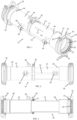
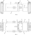
- FIG. 1-5 illustrate an adjustable-length anti-corrosion pipe system 10.
- the anti-corrosion pipe system 10 includes a first pipe section 12 that is arranged to slide in and out of a second pipe section 14.
- the first and second pipe sections 12 and 14 are telescopic with each other.
- an outer end 16 of first pipe section 12 is equipped with a pipe connection 18 for receiving therein a pipe (not shown; such as another pipe in a water piping system).
- the pipe connection 18 is provided with an annular seal 19 plus a grip ring 20 for sealing the pipe which is inserted into the pipe connection 18.
- the annular seal 19, which may be made of a natural or artificial elastomeric material, may include one or more layers nested in each other. In this manner, one of the nested seals can be removed to accommodate sealing against pipes of different diameters.
- Annular seal 19 may be located axially inwards of the grip ring 20; alternatively annular seal 19 may be located axially outwards of the grip ring 20.
- One or more of the layers of annular seal 19 may include an outer portion folded over an inner portion so as to define an inner space between and bounded by the inner and outer portions.
- the inner space is in fluid communication with a fluid flowing in the pipe. The fluid enters the inner space and applies pressure therein to increase tightening of the seal.
- Grip ring 20 includes wedge-shaped grip elements 22 that are radially spaced from one another about a ring member, such as springs that connect adjacent grip rings with one another.
- the grip elements 22 are formed with teeth that face inwards towards the center of the grip ring 20.
- One or more tightening elements 24 e.g., bolts and nuts or other tightenable fasteners
- Annular seal 19 is radially squeezed and sealingly clamped against the outside surface of the pipe when tightening elements 24 fasten and tighten clamp members 26 towards each other.
- the teeth of the wedge-shaped grip elements 22 are forced into the outside surface of the pipe when tightening elements 24 fasten and tighten clamp members 26 towards each other.
- the clamp members 26 may be formed at ends of a continuous, partial ring; alternatively, as shown, the ring is not continuous but rather is formed of two sections clamped together opposite to the clamp members 26 by fasteners 28 that pass through lugs 30.
- an outer end 32 of second pipe section 14 is also equipped with the same type of pipe connection 18 for receiving therein a pipe (not shown; such as another pipe in a water piping system).
- first pipe section 12 and second pipe section 14 are arranged, and together define a total length, along a longitudinal axis 15, and first and second pipe sections 12 and 14 are movable with respect to each other so as to shorten or lengthen the total length.
- the telescoping first and second pipe sections 12 and 14 are easily adjusted on site in the field to a desired length. They are then fixed at the desired length by two different fixation members. First, an annular fixation member 42 clamps a portion of second pipe section 14 to a portion of first pipe section 12.
- the annular fixation member 42 may include annular seal 19 described above.
- one or more axial fixation members 34 are secured to lugs 36 and 38 extending from first and second pipe sections 12 and 14, respectively.
- the axial fixation member 34 may be secured to lugs 36 and 38 by means of nuts 39 (which tighten against the lug) and an electrically insulating bushing (insulator) 40 (such as a plastic bushing) that sits in each of lugs 36 and 38.
- the electrically insulating bushing 40 ensures no electrical current is passed between first and second pipe sections 12 and 14.
- the axial fixation members 34 may be electrically insulating or have an electrically insulating portion.
- first and second pipe sections 12 and 14 may be made of ductile iron, cast iron, steel alloy and other metals.
- the first and second pipe sections 12 and 14 may each be coated with an anti-corrosion coating against the effects of stray current, such as but not limited to, a fusion bonded epoxy coating, a polyurethane coating or others.
- first and/or second pipe sections 12 and 14 may include a cathodic protection outlet 44, such as but not limited to, a threaded lug (e.g., 1/4-20 UNC), to which sacrificial corrosion elements may be attached (the sacrificial corrosion elements corrode instead of the pipes, due to galvanic corrosion) or to which electrical conductors may be attached.
- first and second pipe sections 12 and 14 may include a lifting ear 46.
- Figs. 1-3 show the adjustable-length anti-corrosion pipe system 10 in an elongate, extended orientation.
- Figs. 4-5 show the adjustable-length anti-corrosion pipe system 10 in a contracted orientation.
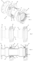
- FIGs. 6-8 illustrate an adjustable-length anti-corrosion pipe system 50, constructed and operative in accordance with a non-limiting embodiment of the present invention.
- Pipe system 50 is similar to pipe system 10, with like elements being designated by like numerals.
- Pipe system 50 differs from pipe system 10 in that there are no axial fixation members. Instead, an annular fixation member 52 is used to achieve electrical insulation between first and second pipe sections 12 and 14.
- the annular fixation member 52 does not only include annular seal 19, but instead includes pipe connection 18, which as before, is provided with annular seal 19 plus grip ring 20.
- the annular fixation member 52 tightens grip ring 20 against an electrically insulating sleeve 53 (also referred to as insulator 53) wrapped around the outer contour of first pipe section 12.
- the electrically insulating sleeve 53 may be made of an elastomeric material.
- the teeth of grip ring 20 bite into sleeve 53, but do not pierce sleeve 53, and thus do not contact the metal pipe 12.
- the tightening of annular fixation member 52 against sleeve 53 achieves electrical insulation between first and second pipe sections 12 and 14.
- pipe system 50 Another difference from pipe system 10 is that in pipe system 50 the outer end of second pipe section 14 is provided with a flange 54 instead of a pipe connection.
- FIG. 9 illustrates an adjustable-length anti-corrosion pipe system 60, constructed and operative in accordance with another non-limiting embodiment of the present invention.
- Pipe system 60 is similar to pipe system 50, with like elements being designated by like numerals.
- Pipe system 60 differs from pipe system 50 in that the outer ends of both first and second pipe sections 12 and 14 are provided with flanges 54.
Landscapes
- Engineering & Computer Science (AREA)
- General Engineering & Computer Science (AREA)
- Mechanical Engineering (AREA)
- Prevention Of Electric Corrosion (AREA)
- Protection Of Pipes Against Damage, Friction, And Corrosion (AREA)
Claims (8)
- Rohrsystem (10), umfassend:einen ersten Rohrteil (12) und einen zweiten Rohrteil (14), die entlang einer Längsachse (15) angeordnet sind und zusammen eine Gesamtlänge definieren, wobei der erste und der zweite Rohrteil (12, 14) in Bezug zueinander beweglich sind, um die Gesamtlänge in einer zusammengezogenen Ausrichtung zu verkürzen oder die Gesamtlänge in einer gestreckten, ausgedehnten Ausrichtung zu verlängern; undein Befestigungselement (34, 52), das einen Abschnitt des zweiten Rohrteils (14) an einen Abschnitt des ersten Rohrteils (12) sowohl in der zusammengezogenen Ausrichtung als auch in der gestreckten Ausrichtung klemmt, wobei das Befestigungselement (34, 52) einen Isolator (34, 40, 53) umfasst, der elektrisch isolierend ist und keinen elektrischen Strom zwischen dem ersten und dem zweiten Rohrteil (12, 14) durchlässt, wobei der erste und der zweite Rohrteil (12, 14) teleskopisch miteinander verbunden sind, dadurch gekennzeichnet, dassdas Befestigungselement (52) ein ringförmiges Befestigungselement (52) umfasst, das einen Greifring (20) umfasst, der gegen eine elektrisch isolierende Hülse (53) klemmt, die um eine äußere Kontur des ersten Rohrteils (12) gewickelt ist, wobei der Greifring (20) die Hülse (53) nicht durchstößt.
- Rohrsystem (10) gemäß Anspruch 1, wobei das Befestigungselement (34) eines oder mehrere axiale Befestigungselemente (34) umfasst.
- Rohrsystem (10) gemäß Anspruch 2, wobei das eine oder die mehreren axialen Befestigungselemente (34) einen elektrisch isolierenden Abschnitt aufweisen.
- Rohrsystem (10) gemäß Anspruch 2, wobei das eine oder die mehreren axialen Befestigungselemente (34) an Laschen (36, 38) befestigt sind, die sich von dem ersten bzw. zweiten Rohrteil (12, 14) erstrecken, und der Isolator (40) eine elektrisch isolierende Buchse (40) umfasst, die in jeder der Laschen (36, 38) sitzt.
- Rohrsystem (10) gemäß Anspruch 1, wobei mindestens eines der äußeren Enden (16, 32) des ersten bzw. zweiten Rohrteils (12, 14) eine Rohrverbindung (18) umfasst, und die Rohrverbindung (18) eine ringförmige Dichtung (19) sowie einen Greifring (20) umfasst.
- Rohrsystem (10) gemäß Anspruch 1, wobei der erste und der zweite Rohrteil (12, 14) mit einem Korrosionsschutzüberzug überzogen sind.
- Rohrsystem (10) gemäß Anspruch 1, wobei mindestens einer der ersten und zweiten Rohrteile (12, 14) einen kathodischen Schutzauslass (44) aufweist.
- Rohrsystem (10) gemäß Anspruch 1, wobei mindestens einer der ersten und zweiten Rohrteile (12, 14) eine Hebeöse (46) aufweist.
Applications Claiming Priority (2)
| Application Number | Priority Date | Filing Date | Title |
|---|---|---|---|
| US15/825,407 US10900597B2 (en) | 2017-11-29 | 2017-11-29 | Anti-corrosion pipe system with adjustable length |
| PCT/IB2018/059221 WO2019106500A1 (en) | 2017-11-29 | 2018-11-22 | Anti-corrosion pipe system with adjustable length |
Publications (2)
| Publication Number | Publication Date |
|---|---|
| EP3717820A1 EP3717820A1 (de) | 2020-10-07 |
| EP3717820B1 true EP3717820B1 (de) | 2024-05-22 |
Family
ID=64901016
Family Applications (1)
| Application Number | Title | Priority Date | Filing Date |
|---|---|---|---|
| EP18826797.5A Active EP3717820B1 (de) | 2017-11-29 | 2018-11-22 | Elekrtisch isoliertes rohrsystem mit einstellbarer länge |
Country Status (6)
| Country | Link |
|---|---|
| US (1) | US10900597B2 (de) |
| EP (1) | EP3717820B1 (de) |
| CA (1) | CA3082078C (de) |
| DK (1) | DK3717820T3 (de) |
| ES (1) | ES2981904T3 (de) |
| WO (1) | WO2019106500A1 (de) |
Families Citing this family (17)
| Publication number | Priority date | Publication date | Assignee | Title |
|---|---|---|---|---|
| US10844983B2 (en) * | 2017-07-13 | 2020-11-24 | Mueller International, Llc | Top bar coupling |
| US10871248B2 (en) | 2018-02-28 | 2020-12-22 | Mueller International, Llc | Coupling gasket with friction-fit range reducer |
| US10914412B2 (en) | 2018-06-28 | 2021-02-09 | Watts Regulator Co. | Backflow prevention assembly having a variable lay-length and orientation |
| USD944366S1 (en) | 2019-03-08 | 2022-02-22 | Watts Industries Italia S.R.L. | Static balancing valve |
| EP3705866B1 (de) | 2019-03-08 | 2023-09-20 | WATTS INDUSTRIES ITALIA S.r.l. | Differenzdrucksensor mit magnetischem einstellrad |
| US11795666B2 (en) | 2019-05-08 | 2023-10-24 | Watts Regulator Co. | Wireless communication system within a mechanical room |
| US11815424B2 (en) | 2019-05-08 | 2023-11-14 | Watts Regulator Co. | Backflow prevention system test cock with a fluid sensor |
| EP3835494A1 (de) | 2019-12-10 | 2021-06-16 | Watts Regulator Co. | System zur überwachung des zustands eines rückflussverhinderers |
| US12195954B2 (en) | 2019-12-10 | 2025-01-14 | Watts Regulator Co. | System for monitoring backflow preventer condition |
| US11585076B2 (en) | 2020-01-24 | 2023-02-21 | Watts Regulator Co. | Apparatus and method for valve cartridge extraction |
| IT202000009817A1 (it) * | 2020-05-05 | 2021-11-05 | Pipes & Fittings Eqofluids S L | Sistema di giunzione integrato per elementi tubolari di distribuzione dei fluidi |
| US11719352B2 (en) | 2020-08-17 | 2023-08-08 | Watts Regulator Co. | Check cover assemblies for backflow prevention assemblies with integrated test cock protection shroud |
| US11773992B2 (en) | 2020-08-17 | 2023-10-03 | Watts Regulator Co. | Backflow prevention assembly with a linkage |
| US11739507B2 (en) | 2020-12-09 | 2023-08-29 | Watts Regulator Co. | Test cock with integrated extraction tool |
| USD1021000S1 (en) | 2021-08-17 | 2024-04-02 | Watts Regulator Co. | Valve assembly and body for same |
| CN115164105B (zh) * | 2022-05-20 | 2023-09-29 | 江苏常宝滔邦石油管件有限公司 | 一种具有绝热补偿功能的石油管件密封连接装置 |
| FR3153123B1 (fr) * | 2023-09-14 | 2025-10-10 | Airbus Operations Sas | Ensemble de canalisations comportant un système de maintien amélioré |
Citations (1)
| Publication number | Priority date | Publication date | Assignee | Title |
|---|---|---|---|---|
| EP2392845A1 (de) * | 2009-01-27 | 2011-12-07 | Kubota Corporation | Rohrverbindung |
Family Cites Families (13)
| Publication number | Priority date | Publication date | Assignee | Title |
|---|---|---|---|---|
| US1983228A (en) | 1933-07-24 | 1934-12-04 | United Gas Improvement Co | Bolted pipe joint |
| US3278202A (en) | 1964-05-14 | 1966-10-11 | Joseph B Smith | Insulated pipe joint |
| EP0170129A1 (de) | 1984-07-11 | 1986-02-05 | Henri Stanislaus St. Onge | Methode und Vorrichtung für den kathodischen Schutz der metallischen Rohrleitungen |
| US6257625B1 (en) * | 1999-04-23 | 2001-07-10 | Taisei Kiko Co., Ltd. | Flexible joint and long nut for flexible joint |
| US7384076B2 (en) * | 2004-10-22 | 2008-06-10 | Ebaa Iron, Inc. | Pipe ring apparatus and method |
| US7997626B2 (en) | 2009-08-06 | 2011-08-16 | Krausz Industries Development Ltd | Pipe coupling with auxiliary clamp |
| US20120025524A1 (en) * | 2010-07-30 | 2012-02-02 | Eliezer Krausz | Grip ring assembly |
| JP5991787B2 (ja) * | 2011-08-22 | 2016-09-14 | ビクターリック カンパニー | 伸縮継手 |
| WO2013027213A2 (en) * | 2011-08-22 | 2013-02-28 | Mekorot Water Company Ltd. | Pipe insulating joint |
| US8764066B1 (en) * | 2012-09-21 | 2014-07-01 | Tyler S. Rice | Expansion coupling system |
| US20140319826A1 (en) | 2013-04-25 | 2014-10-30 | Avi Chiproot | Coupling for range of pipe diameters |
| US9765912B2 (en) * | 2014-11-06 | 2017-09-19 | Spears Manufacturing Co. | Telescoping pipe coupling |
| US9933093B2 (en) * | 2014-11-28 | 2018-04-03 | Embraer S.A. | Aircraft fuel line couplings in compliance with survivable crash and lightning strike requirements |
-
2017
- 2017-11-29 US US15/825,407 patent/US10900597B2/en active Active
-
2018
- 2018-11-22 ES ES18826797T patent/ES2981904T3/es active Active
- 2018-11-22 DK DK18826797.5T patent/DK3717820T3/da active
- 2018-11-22 EP EP18826797.5A patent/EP3717820B1/de active Active
- 2018-11-22 CA CA3082078A patent/CA3082078C/en active Active
- 2018-11-22 WO PCT/IB2018/059221 patent/WO2019106500A1/en not_active Ceased
Patent Citations (1)
| Publication number | Priority date | Publication date | Assignee | Title |
|---|---|---|---|---|
| EP2392845A1 (de) * | 2009-01-27 | 2011-12-07 | Kubota Corporation | Rohrverbindung |
Also Published As
| Publication number | Publication date |
|---|---|
| DK3717820T3 (da) | 2024-08-05 |
| CA3082078A1 (en) | 2019-06-06 |
| WO2019106500A1 (en) | 2019-06-06 |
| US20190162341A1 (en) | 2019-05-30 |
| EP3717820A1 (de) | 2020-10-07 |
| CA3082078C (en) | 2023-10-10 |
| US10900597B2 (en) | 2021-01-26 |
| ES2981904T3 (es) | 2024-10-14 |
Similar Documents
| Publication | Publication Date | Title |
|---|---|---|
| EP3717820B1 (de) | Elekrtisch isoliertes rohrsystem mit einstellbarer länge | |
| US4779900A (en) | Segmented pipe joint retainer glands | |
| US7384076B2 (en) | Pipe ring apparatus and method | |
| JP4303829B2 (ja) | 自在パイプコネクタ及び所定の直径のパイプの端でシールされた接続を達成するための方法 | |
| US4896903A (en) | Segmented pipe joint retainer glands | |
| CN109424807B (zh) | 榫槽连接接合器 | |
| EP2932145B1 (de) | Gelenkbrücke für eine klemmvorrichtung | |
| US8445782B2 (en) | Flexible conduit coupling connector | |
| US3628815A (en) | Conduit connection means | |
| KR20210131531A (ko) | 개량된 커플링장치 | |
| US20040108713A1 (en) | Clamp to anode connection | |
| US20050166988A1 (en) | Assembly and method for stiffening a flexible pipe | |
| RU2174637C1 (ru) | Диэлектрическое фланцевое соединение трубопровода | |
| GB2253452A (en) | Pipe couplings | |
| US4676275A (en) | 360 Degree pipe repair clamp | |
| US4250350A (en) | Expansion joint with interior grounding continuity bond | |
| EP2867571B1 (de) | Rohrreparaturausrüstung | |
| US2511343A (en) | Prefabricated piping system | |
| RU2162981C2 (ru) | Фланцевое соединение на высокое давление с диэлектрическим разъемом трубопровода | |
| GB2305481A (en) | Pipe coupling with gasket and housing | |
| RU2123150C1 (ru) | Устройство защиты труб от коррозии | |
| US4936609A (en) | Connector for pipe joint | |
| US20200271255A1 (en) | Pipe coupling with protection against fastener shearing | |
| RU2014544C1 (ru) | Соединение металлопластовых труб | |
| JP2840016B2 (ja) | 消火配管用分散ヘッダの接続構造 |
Legal Events
| Date | Code | Title | Description |
|---|---|---|---|
| STAA | Information on the status of an ep patent application or granted ep patent |
Free format text: STATUS: UNKNOWN |
|
| STAA | Information on the status of an ep patent application or granted ep patent |
Free format text: STATUS: THE INTERNATIONAL PUBLICATION HAS BEEN MADE |
|
| PUAI | Public reference made under article 153(3) epc to a published international application that has entered the european phase |
Free format text: ORIGINAL CODE: 0009012 |
|
| STAA | Information on the status of an ep patent application or granted ep patent |
Free format text: STATUS: REQUEST FOR EXAMINATION WAS MADE |
|
| 17P | Request for examination filed |
Effective date: 20200515 |
|
| AK | Designated contracting states |
Kind code of ref document: A1 Designated state(s): AL AT BE BG CH CY CZ DE DK EE ES FI FR GB GR HR HU IE IS IT LI LT LU LV MC MK MT NL NO PL PT RO RS SE SI SK SM TR |
|
| AX | Request for extension of the european patent |
Extension state: BA ME |
|
| DAV | Request for validation of the european patent (deleted) | ||
| DAX | Request for extension of the european patent (deleted) | ||
| STAA | Information on the status of an ep patent application or granted ep patent |
Free format text: STATUS: EXAMINATION IS IN PROGRESS |
|
| 17Q | First examination report despatched |
Effective date: 20220527 |
|
| GRAP | Despatch of communication of intention to grant a patent |
Free format text: ORIGINAL CODE: EPIDOSNIGR1 |
|
| STAA | Information on the status of an ep patent application or granted ep patent |
Free format text: STATUS: GRANT OF PATENT IS INTENDED |
|
| GRAS | Grant fee paid |
Free format text: ORIGINAL CODE: EPIDOSNIGR3 |
|
| GRAA | (expected) grant |
Free format text: ORIGINAL CODE: 0009210 |
|
| STAA | Information on the status of an ep patent application or granted ep patent |
Free format text: STATUS: THE PATENT HAS BEEN GRANTED |
|
| INTG | Intention to grant announced |
Effective date: 20240326 |
|
| RAP3 | Party data changed (applicant data changed or rights of an application transferred) |
Owner name: KRAUSZ INDUSTRIES LTD. |
|
| AK | Designated contracting states |
Kind code of ref document: B1 Designated state(s): AL AT BE BG CH CY CZ DE DK EE ES FI FR GB GR HR HU IE IS IT LI LT LU LV MC MK MT NL NO PL PT RO RS SE SI SK SM TR |
|
| REG | Reference to a national code |
Ref country code: GB Ref legal event code: FG4D |
|
| REG | Reference to a national code |
Ref country code: CH Ref legal event code: EP |
|
| REG | Reference to a national code |
Ref country code: DE Ref legal event code: R096 Ref document number: 602018069852 Country of ref document: DE |
|
| REG | Reference to a national code |
Ref country code: IE Ref legal event code: FG4D |
|
| REG | Reference to a national code |
Ref country code: NL Ref legal event code: FP |
|
| REG | Reference to a national code |
Ref country code: DK Ref legal event code: T3 Effective date: 20240730 |
|
| REG | Reference to a national code |
Ref country code: LT Ref legal event code: MG9D |
|
| PG25 | Lapsed in a contracting state [announced via postgrant information from national office to epo] |
Ref country code: IS Free format text: LAPSE BECAUSE OF FAILURE TO SUBMIT A TRANSLATION OF THE DESCRIPTION OR TO PAY THE FEE WITHIN THE PRESCRIBED TIME-LIMIT Effective date: 20240922 |
|
| PG25 | Lapsed in a contracting state [announced via postgrant information from national office to epo] |
Ref country code: BG Free format text: LAPSE BECAUSE OF FAILURE TO SUBMIT A TRANSLATION OF THE DESCRIPTION OR TO PAY THE FEE WITHIN THE PRESCRIBED TIME-LIMIT Effective date: 20240522 |
|
| PG25 | Lapsed in a contracting state [announced via postgrant information from national office to epo] |
Ref country code: HR Free format text: LAPSE BECAUSE OF FAILURE TO SUBMIT A TRANSLATION OF THE DESCRIPTION OR TO PAY THE FEE WITHIN THE PRESCRIBED TIME-LIMIT Effective date: 20240522 Ref country code: FI Free format text: LAPSE BECAUSE OF FAILURE TO SUBMIT A TRANSLATION OF THE DESCRIPTION OR TO PAY THE FEE WITHIN THE PRESCRIBED TIME-LIMIT Effective date: 20240522 |
|
| PG25 | Lapsed in a contracting state [announced via postgrant information from national office to epo] |
Ref country code: GR Free format text: LAPSE BECAUSE OF FAILURE TO SUBMIT A TRANSLATION OF THE DESCRIPTION OR TO PAY THE FEE WITHIN THE PRESCRIBED TIME-LIMIT Effective date: 20240823 |
|
| PG25 | Lapsed in a contracting state [announced via postgrant information from national office to epo] |
Ref country code: PT Free format text: LAPSE BECAUSE OF FAILURE TO SUBMIT A TRANSLATION OF THE DESCRIPTION OR TO PAY THE FEE WITHIN THE PRESCRIBED TIME-LIMIT Effective date: 20240923 |
|
| REG | Reference to a national code |
Ref country code: ES Ref legal event code: FG2A Ref document number: 2981904 Country of ref document: ES Kind code of ref document: T3 Effective date: 20241014 |
|
| PG25 | Lapsed in a contracting state [announced via postgrant information from national office to epo] |
Ref country code: PL Free format text: LAPSE BECAUSE OF FAILURE TO SUBMIT A TRANSLATION OF THE DESCRIPTION OR TO PAY THE FEE WITHIN THE PRESCRIBED TIME-LIMIT Effective date: 20240522 |
|
| PG25 | Lapsed in a contracting state [announced via postgrant information from national office to epo] |
Ref country code: LV Free format text: LAPSE BECAUSE OF FAILURE TO SUBMIT A TRANSLATION OF THE DESCRIPTION OR TO PAY THE FEE WITHIN THE PRESCRIBED TIME-LIMIT Effective date: 20240522 |
|
| PG25 | Lapsed in a contracting state [announced via postgrant information from national office to epo] |
Ref country code: PT Free format text: LAPSE BECAUSE OF FAILURE TO SUBMIT A TRANSLATION OF THE DESCRIPTION OR TO PAY THE FEE WITHIN THE PRESCRIBED TIME-LIMIT Effective date: 20240923 Ref country code: PL Free format text: LAPSE BECAUSE OF FAILURE TO SUBMIT A TRANSLATION OF THE DESCRIPTION OR TO PAY THE FEE WITHIN THE PRESCRIBED TIME-LIMIT Effective date: 20240522 Ref country code: NO Free format text: LAPSE BECAUSE OF FAILURE TO SUBMIT A TRANSLATION OF THE DESCRIPTION OR TO PAY THE FEE WITHIN THE PRESCRIBED TIME-LIMIT Effective date: 20240822 Ref country code: LV Free format text: LAPSE BECAUSE OF FAILURE TO SUBMIT A TRANSLATION OF THE DESCRIPTION OR TO PAY THE FEE WITHIN THE PRESCRIBED TIME-LIMIT Effective date: 20240522 Ref country code: IS Free format text: LAPSE BECAUSE OF FAILURE TO SUBMIT A TRANSLATION OF THE DESCRIPTION OR TO PAY THE FEE WITHIN THE PRESCRIBED TIME-LIMIT Effective date: 20240922 Ref country code: HR Free format text: LAPSE BECAUSE OF FAILURE TO SUBMIT A TRANSLATION OF THE DESCRIPTION OR TO PAY THE FEE WITHIN THE PRESCRIBED TIME-LIMIT Effective date: 20240522 Ref country code: GR Free format text: LAPSE BECAUSE OF FAILURE TO SUBMIT A TRANSLATION OF THE DESCRIPTION OR TO PAY THE FEE WITHIN THE PRESCRIBED TIME-LIMIT Effective date: 20240823 Ref country code: FI Free format text: LAPSE BECAUSE OF FAILURE TO SUBMIT A TRANSLATION OF THE DESCRIPTION OR TO PAY THE FEE WITHIN THE PRESCRIBED TIME-LIMIT Effective date: 20240522 Ref country code: BG Free format text: LAPSE BECAUSE OF FAILURE TO SUBMIT A TRANSLATION OF THE DESCRIPTION OR TO PAY THE FEE WITHIN THE PRESCRIBED TIME-LIMIT Effective date: 20240522 Ref country code: RS Free format text: LAPSE BECAUSE OF FAILURE TO SUBMIT A TRANSLATION OF THE DESCRIPTION OR TO PAY THE FEE WITHIN THE PRESCRIBED TIME-LIMIT Effective date: 20240822 |
|
| REG | Reference to a national code |
Ref country code: AT Ref legal event code: UEP Ref document number: 1689033 Country of ref document: AT Kind code of ref document: T Effective date: 20240522 |
|
| PG25 | Lapsed in a contracting state [announced via postgrant information from national office to epo] |
Ref country code: EE Free format text: LAPSE BECAUSE OF FAILURE TO SUBMIT A TRANSLATION OF THE DESCRIPTION OR TO PAY THE FEE WITHIN THE PRESCRIBED TIME-LIMIT Effective date: 20240522 |
|
| PG25 | Lapsed in a contracting state [announced via postgrant information from national office to epo] |
Ref country code: CZ Free format text: LAPSE BECAUSE OF FAILURE TO SUBMIT A TRANSLATION OF THE DESCRIPTION OR TO PAY THE FEE WITHIN THE PRESCRIBED TIME-LIMIT Effective date: 20240522 |
|
| PG25 | Lapsed in a contracting state [announced via postgrant information from national office to epo] |
Ref country code: SK Free format text: LAPSE BECAUSE OF FAILURE TO SUBMIT A TRANSLATION OF THE DESCRIPTION OR TO PAY THE FEE WITHIN THE PRESCRIBED TIME-LIMIT Effective date: 20240522 Ref country code: RO Free format text: LAPSE BECAUSE OF FAILURE TO SUBMIT A TRANSLATION OF THE DESCRIPTION OR TO PAY THE FEE WITHIN THE PRESCRIBED TIME-LIMIT Effective date: 20240522 |
|
| PG25 | Lapsed in a contracting state [announced via postgrant information from national office to epo] |
Ref country code: SM Free format text: LAPSE BECAUSE OF FAILURE TO SUBMIT A TRANSLATION OF THE DESCRIPTION OR TO PAY THE FEE WITHIN THE PRESCRIBED TIME-LIMIT Effective date: 20240522 |
|
| PG25 | Lapsed in a contracting state [announced via postgrant information from national office to epo] |
Ref country code: SM Free format text: LAPSE BECAUSE OF FAILURE TO SUBMIT A TRANSLATION OF THE DESCRIPTION OR TO PAY THE FEE WITHIN THE PRESCRIBED TIME-LIMIT Effective date: 20240522 Ref country code: SK Free format text: LAPSE BECAUSE OF FAILURE TO SUBMIT A TRANSLATION OF THE DESCRIPTION OR TO PAY THE FEE WITHIN THE PRESCRIBED TIME-LIMIT Effective date: 20240522 Ref country code: RO Free format text: LAPSE BECAUSE OF FAILURE TO SUBMIT A TRANSLATION OF THE DESCRIPTION OR TO PAY THE FEE WITHIN THE PRESCRIBED TIME-LIMIT Effective date: 20240522 Ref country code: EE Free format text: LAPSE BECAUSE OF FAILURE TO SUBMIT A TRANSLATION OF THE DESCRIPTION OR TO PAY THE FEE WITHIN THE PRESCRIBED TIME-LIMIT Effective date: 20240522 Ref country code: CZ Free format text: LAPSE BECAUSE OF FAILURE TO SUBMIT A TRANSLATION OF THE DESCRIPTION OR TO PAY THE FEE WITHIN THE PRESCRIBED TIME-LIMIT Effective date: 20240522 |
|
| REG | Reference to a national code |
Ref country code: DE Ref legal event code: R097 Ref document number: 602018069852 Country of ref document: DE |
|
| PLBE | No opposition filed within time limit |
Free format text: ORIGINAL CODE: 0009261 |
|
| STAA | Information on the status of an ep patent application or granted ep patent |
Free format text: STATUS: NO OPPOSITION FILED WITHIN TIME LIMIT |
|
| PG25 | Lapsed in a contracting state [announced via postgrant information from national office to epo] |
Ref country code: SI Free format text: LAPSE BECAUSE OF FAILURE TO SUBMIT A TRANSLATION OF THE DESCRIPTION OR TO PAY THE FEE WITHIN THE PRESCRIBED TIME-LIMIT Effective date: 20240522 |
|
| 26N | No opposition filed |
Effective date: 20250225 |
|
| PG25 | Lapsed in a contracting state [announced via postgrant information from national office to epo] |
Ref country code: MC Free format text: LAPSE BECAUSE OF FAILURE TO SUBMIT A TRANSLATION OF THE DESCRIPTION OR TO PAY THE FEE WITHIN THE PRESCRIBED TIME-LIMIT Effective date: 20240522 |
|
| PG25 | Lapsed in a contracting state [announced via postgrant information from national office to epo] |
Ref country code: LU Free format text: LAPSE BECAUSE OF NON-PAYMENT OF DUE FEES Effective date: 20241122 |
|
| REG | Reference to a national code |
Ref country code: BE Ref legal event code: MM Effective date: 20241130 |
|
| PG25 | Lapsed in a contracting state [announced via postgrant information from national office to epo] |
Ref country code: SE Free format text: LAPSE BECAUSE OF FAILURE TO SUBMIT A TRANSLATION OF THE DESCRIPTION OR TO PAY THE FEE WITHIN THE PRESCRIBED TIME-LIMIT Effective date: 20240522 |
|
| PG25 | Lapsed in a contracting state [announced via postgrant information from national office to epo] |
Ref country code: BE Free format text: LAPSE BECAUSE OF NON-PAYMENT OF DUE FEES Effective date: 20241130 |
|
| PG25 | Lapsed in a contracting state [announced via postgrant information from national office to epo] |
Ref country code: IE Free format text: LAPSE BECAUSE OF NON-PAYMENT OF DUE FEES Effective date: 20241122 |
|
| REG | Reference to a national code |
Ref country code: CH Ref legal event code: U11 Free format text: ST27 STATUS EVENT CODE: U-0-0-U10-U11 (AS PROVIDED BY THE NATIONAL OFFICE) Effective date: 20251201 |
|
| PGFP | Annual fee paid to national office [announced via postgrant information from national office to epo] |
Ref country code: NL Payment date: 20251119 Year of fee payment: 8 |
|
| PGFP | Annual fee paid to national office [announced via postgrant information from national office to epo] |
Ref country code: DE Payment date: 20251119 Year of fee payment: 8 |
|
| PGFP | Annual fee paid to national office [announced via postgrant information from national office to epo] |
Ref country code: GB Payment date: 20251121 Year of fee payment: 8 |
|
| PGFP | Annual fee paid to national office [announced via postgrant information from national office to epo] |
Ref country code: AT Payment date: 20251120 Year of fee payment: 8 |
|
| PGFP | Annual fee paid to national office [announced via postgrant information from national office to epo] |
Ref country code: IT Payment date: 20251125 Year of fee payment: 8 Ref country code: DK Payment date: 20251125 Year of fee payment: 8 |
|
| PGFP | Annual fee paid to national office [announced via postgrant information from national office to epo] |
Ref country code: FR Payment date: 20251126 Year of fee payment: 8 |
|
| PGFP | Annual fee paid to national office [announced via postgrant information from national office to epo] |
Ref country code: CH Payment date: 20251201 Year of fee payment: 8 |
|
| PGFP | Annual fee paid to national office [announced via postgrant information from national office to epo] |
Ref country code: ES Payment date: 20251229 Year of fee payment: 8 |
|
| PG25 | Lapsed in a contracting state [announced via postgrant information from national office to epo] |
Ref country code: HU Free format text: LAPSE BECAUSE OF FAILURE TO SUBMIT A TRANSLATION OF THE DESCRIPTION OR TO PAY THE FEE WITHIN THE PRESCRIBED TIME-LIMIT; INVALID AB INITIO Effective date: 20181122 |
|
| PG25 | Lapsed in a contracting state [announced via postgrant information from national office to epo] |
Ref country code: CY Free format text: LAPSE BECAUSE OF FAILURE TO SUBMIT A TRANSLATION OF THE DESCRIPTION OR TO PAY THE FEE WITHIN THE PRESCRIBED TIME-LIMIT; INVALID AB INITIO Effective date: 20181122 |