EP3717689B1 - Tumble dryer with a heat pump system - Google Patents
Tumble dryer with a heat pump system Download PDFInfo
- Publication number
- EP3717689B1 EP3717689B1 EP17804568.8A EP17804568A EP3717689B1 EP 3717689 B1 EP3717689 B1 EP 3717689B1 EP 17804568 A EP17804568 A EP 17804568A EP 3717689 B1 EP3717689 B1 EP 3717689B1
- Authority
- EP
- European Patent Office
- Prior art keywords
- air flow
- constriction
- evaporator
- tumble dryer
- openings
- Prior art date
- Legal status (The legal status is an assumption and is not a legal conclusion. Google has not performed a legal analysis and makes no representation as to the accuracy of the status listed.)
- Active
Links
Images

Classifications
-
- D—TEXTILES; PAPER
- D06—TREATMENT OF TEXTILES OR THE LIKE; LAUNDERING; FLEXIBLE MATERIALS NOT OTHERWISE PROVIDED FOR
- D06F—LAUNDERING, DRYING, IRONING, PRESSING OR FOLDING TEXTILE ARTICLES
- D06F58/00—Domestic laundry dryers
- D06F58/20—General details of domestic laundry dryers
- D06F58/206—Heat pump arrangements
-
- D—TEXTILES; PAPER
- D06—TREATMENT OF TEXTILES OR THE LIKE; LAUNDERING; FLEXIBLE MATERIALS NOT OTHERWISE PROVIDED FOR
- D06F—LAUNDERING, DRYING, IRONING, PRESSING OR FOLDING TEXTILE ARTICLES
- D06F2103/00—Parameters monitored or detected for the control of domestic laundry washing machines, washer-dryers or laundry dryers
- D06F2103/28—Air properties
- D06F2103/36—Flow or velocity
-
- D—TEXTILES; PAPER
- D06—TREATMENT OF TEXTILES OR THE LIKE; LAUNDERING; FLEXIBLE MATERIALS NOT OTHERWISE PROVIDED FOR
- D06F—LAUNDERING, DRYING, IRONING, PRESSING OR FOLDING TEXTILE ARTICLES
- D06F2103/00—Parameters monitored or detected for the control of domestic laundry washing machines, washer-dryers or laundry dryers
- D06F2103/50—Parameters monitored or detected for the control of domestic laundry washing machines, washer-dryers or laundry dryers related to heat pumps, e.g. pressure or flow rate
-
- D—TEXTILES; PAPER
- D06—TREATMENT OF TEXTILES OR THE LIKE; LAUNDERING; FLEXIBLE MATERIALS NOT OTHERWISE PROVIDED FOR
- D06F—LAUNDERING, DRYING, IRONING, PRESSING OR FOLDING TEXTILE ARTICLES
- D06F2105/00—Systems or parameters controlled or affected by the control systems of washing machines, washer-dryers or laundry dryers
- D06F2105/26—Heat pumps
-
- D—TEXTILES; PAPER
- D06—TREATMENT OF TEXTILES OR THE LIKE; LAUNDERING; FLEXIBLE MATERIALS NOT OTHERWISE PROVIDED FOR
- D06F—LAUNDERING, DRYING, IRONING, PRESSING OR FOLDING TEXTILE ARTICLES
- D06F58/00—Domestic laundry dryers
- D06F58/02—Domestic laundry dryers having dryer drums rotating about a horizontal axis
- D06F58/04—Details
Definitions
- the present invention relates to a tumble dryer, especially to a tumble dryer comprising a heat pump system.
- EP 3 118 365 shows an example of a tumble dryer with a heat pump system.
- the air that is used to dry the laundry is circulated in an air flow circuit.
- hot dry air is blown by a fan into the drying drum for removal of moisture from wet laundry.
- the warm humidified air leaves the drum and is cooled and dehumidified in an evaporator.
- the cooled air is then heated in a condenser and blown into the drying drum again.
- a general problem with tumble dryers is how to improve their efficiency further.
- tumble dryers there are more examples of tumble dryers in prior art, a few are listed below:
- the tumble dryer comprising a heat pump system and an air flow circuit for circulation of an air flow.
- the air flow circuit comprises a condenser, a drying drum, a fan arrangement, an air flow duct, and an evaporator.
- the air flow duct comprises a constriction/diffuser, arranged upstream of the evaporator.
- the constriction is provided with a plurality of openings, distributed over a cross section of the air flow duct and the constriction creates a pressure drop in the air flow that is circulated in the air flow duct, when the air flow flows from a first side of the constriction to a second side of the constriction.
- the openings in the constriction are adapted to distribute the air flow over the cross section of the air flow duct.
- the openings may constitute at least 1/3 of surface of the constriction.
- the percentage of openings may depend on the size of the air flow duct and hence the size of the laundry dryer. However, it may be advantageous if at least 1/3 of the constriction surface may consist of openings to have the desired air flow distribution.
- the distance between the constriction and the surface of the evaporator is between 0-300 mm, preferably between 10 mm and 40 mm.
- the constriction is a perforated plate.
- the perforated plate may be a sheet metal, or a metal mesh may be arranged in the air flow duct to provide a constriction.
- the tumble dryer's rotatable drum may comprise a circular rear wall with air inlet openings and a radial cylindrical wall with air outlet openings.
- a space outside the drum's cylindrical periphery may be configured as a duct leading to a filter placed below the drum. This reduces air flow restrictions, and allows the use of a large filter, even about as wide as the diameter of the drum.
Landscapes
- Engineering & Computer Science (AREA)
- Textile Engineering (AREA)
- Detail Structures Of Washing Machines And Dryers (AREA)
Description
- The present invention relates to a tumble dryer, especially to a tumble dryer comprising a heat pump system.
- In tumble dryers, the heat pump technology is an efficient way to save energy during drying of laundry.
EP 3 118 365 shows an example of a tumble dryer with a heat pump system. The air that is used to dry the laundry is circulated in an air flow circuit. In the air flow circuit, hot dry air is blown by a fan into the drying drum for removal of moisture from wet laundry. The warm humidified air leaves the drum and is cooled and dehumidified in an evaporator. The cooled air is then heated in a condenser and blown into the drying drum again. A general problem with tumble dryers is how to improve their efficiency further. - There are more examples of tumble dryers in prior art, a few are listed below:
-
CN 106592182A discloses a drying system and a clothes drying device, and the system comprises a housing, a fan, an evaporator, a condenser, a compressor, and a throttling device. The evaporator and the condenser are oppositely fixed in the housing, and the housing forms an air channel. The evaporator is located between the fan and the condenser in an extending direction of the air channel. The evaporator is disposed in an inclined manner, and is provided with a high end and a low end, which are opposite to each other. The low end of the evaporator is relatively close to the fan, and the high end of the evaporator is relatively close to the condenser. Two side surfaces of the evaporator are respectively a windward side and a leeside, wherein the windward side faces the fan, and the leeside faces the condenser. The housing is provided with an air guide mechanism between the fan and the evaporator, wherein the air guide mechanism is bulged towards an inner cavity of the housing. According to the invention, the air guide mechanism is disposed between the fan and the evaporator, and changes the direction of the air flue on the surface of the evaporator, thereby enabling air which is liable to be centralized at the corners of the evaporator and the housing to flow to the surface of the evaporator, and improving the uniformity of the surface wind field of the evaporator -
US4621438A discloses an energy efficient heat pump dryer for clothes and other washables having a sealed rotatable clothes tumbling drum and means for circulating a stream of heated drying air in a substantially closed path through the tumbling drum. The drum is journaled upon a combined bearing and air seal means at each end. A heat pump is incorporated as the source of heat for the drying air, as a means for recirculating heat from the drying air exhausted from the tumbling drum, and as a means for removing entrained moisture from the exhausted drying air. The dryer is adapted to operate from a 110 volt household power supply and requires no air vent to the outside. -
DE102016200308A1 discloses a household appliance, in particular a tumble dryer, comprising an air duct and a fan unit, which is arranged in the air duct and can generate a flow along a flow direction S, and comprising a throttle device which is arranged in a section of the air duct and which has at least one throttle duct, characterized in that the throttle device is arranged downstream of the fan unit, and that the at least one throttle duct runs essentially parallel to the section of the air duct. -
JP 2017 000483 A - It is an object to obtain a tumble dryer comprising a heat pump system, which has an improved performance.
- This is at least partly achieved by means of a tumble dryer as defined by
claim 1. The tumble dryer comprising a heat pump system and an air flow circuit for circulation of an air flow. The air flow circuit comprises a condenser, a drying drum, a fan arrangement, an air flow duct, and an evaporator. The air flow duct comprises a constriction/diffuser, arranged upstream of the evaporator. The constriction is provided with a plurality of openings, distributed over a cross section of the air flow duct and the constriction creates a pressure drop in the air flow that is circulated in the air flow duct, when the air flow flows from a first side of the constriction to a second side of the constriction. The openings in the constriction are adapted to distribute the air flow over the cross section of the air flow duct. - By arranging a constriction with openings in the air flow duct upstream the evaporator, it becomes possible to allocate the air flow more evenly on a larger part of the evaporator surface. This leads to that a more effective dehumidification of the air flow can be obtained in the evaporator, a shorter drying time in the drying drum, higher performance, and energy savings of the heat pump system.
- The openings may constitute at least 1/3 of surface of the constriction.
- To obtain the desired air flow distribution across the surface of the evaporator, the percentage of openings may depend on the size of the air flow duct and hence the size of the laundry dryer. However, it may be advantageous if at least 1/3 of the constriction surface may consist of openings to have the desired air flow distribution. The distance between the constriction and the surface of the evaporator is between 0-300 mm, preferably between 10 mm and 40 mm.
- The constriction is a perforated plate. For example, the perforated plate may be a sheet metal, or a metal mesh may be arranged in the air flow duct to provide a constriction. These solutions are simple and inexpensive to manufacture.
- The tumble dryer's rotatable drum may comprise a circular rear wall with air inlet openings and a radial cylindrical wall with air outlet openings. A space outside the drum's cylindrical periphery may be configured as a duct leading to a filter placed below the drum. This reduces air flow restrictions, and allows the use of a large filter, even about as wide as the diameter of the drum.
- The above, as well as additional objects, features and advantages of the present invention, will be better understood through the following illustrative and non-limiting detailed description of preferred embodiments of the present invention, with reference to the appended drawings, where the same reference numerals will be used for similar elements, wherein:
-
Fig 1 shows a schematic view of a tumble dryer. -
Fig 2 shows a schematic cross section side view of a tumble dryer comprising a heat pump system, with interior parts exposed. -
Fig 3 shows an enlarged view of the dotted portion X inFig 2 . -
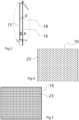
Fig 4 shows a schematic view of a constriction example according to the disclosure. -
Fig 5 shows a schematic view of another constriction example according to the disclosure. -
Fig. 1 illustrates schematically atumble dryer 1 comprising a parallelepiped-shaped housing 2. Adoor 5 is attached by hinges 7 to a front wall 3 of thehousing 2 for input of wet laundry to be dried and for output of dry laundry. -
Fig 2 illustrates a cross section view of atumble dryer 1 comprising aheat pump system 22 and anair flow circuit 21. Theair flow circuit 21 comprises adrying drum 11, afan arrangement 13, anair flow duct 18, anevaporator 15 and acondenser 19. - Wet laundry to be dried is fed into the drying
drum 11 through adoor 5 arranged at the front side 3 of thetumble dryer 1. Warm, dry air may be used for removing moisture from the wet laundry. An air flow may be circulated in anair flow circuit 21, moved through thecircuit 21 by afan arrangement 13. In the shown embodiment, thefan arrangement 13 is situated below thedrying drum 11 but before theevaporator 15. Thefan arrangement 13 could alternatively be located betweencondenser 19 and thedrying drum 11. Due to space considerations in the shown embodiment, the location of thefan arrangement 13 below thedrying drum 11 has been selected. - When the wet laundry is dried in the rotating
drying drum 11, moisture is transferred from the wet laundry to the air flow that is circulated in thedrying drum 11. The warm, humidified air leaves thedrying drum 11 and is circulated to theevaporator 15 through anair flow duct 18. The indicatedair flow duct 18 is located in front of theevaporator 15 directly upstreams thereof with respect to the direction of the air flow. Needless to say theair flow circuit 21 includes a number of ducts and passages to form a closed circuit. - The air flow may be passed through a
filter 12 for separation of particles or lint from the air flow before it enters theevaporator 15. In the embodiment shown, thefilter 12 is arranged below the dryingdrum 13 but above thefan arrangement 15, although other positions are possible. - In the illustrated example, a high-capacity tumble dryer mainly intended for professional use or for use in shared laundry facilities. Such tumble dryers may comprise a
drum 11 with air inlet openings in its circular rear wall and air outlet openings in its radial cylindrical wall, particularly in the front part thereof to provide a process air flow through the drum. This may be combined with a lint removing filter located below the drum, rather than with a filter provided at an outlet located in connection with thefront wall door 5. The space outside the drum's 11 cylindrical periphery may be configured as a duct leading to thefilter 12 under thedrum 11. To a great extent however, the improvements described herein may also be used in connection with typical domestic tumble dryers intended for use a couple of times per week. - The warm, humidified air is passed through the
air flow duct 18 into theevaporator 15, which is made up of ducts (not shown) where warm, humidified air and a refrigerant are led alternately in the ducts and the air flow is cooled down and dehumidified through heat exchange to the refrigerant. - The cooled, dehumidified air is then circulated from the
evaporator 15 to thecondenser 19, where the air flow is heated again through heat exchange with the refrigerant. - The warm air flow is then blown into the drying
drum 11 again. Thearrow 21 indicates the circulation of the air flow in the air flow circuit. - The refrigerant is lead through a refrigerant circuit, where a
compressor 17 compresses the refrigerant, and where the refrigerant is condensed in thecondenser 19 and vaporized in theevaporator 15 after passing an expansion valve (not shown). - The
heat pump system 22, comprising the evaporator, thecompressor 17 and thecondenser 19 and the expansion valve, may be arranged behind the dryingdrum 11 and thefan arrangement 13, along therear side 9 of thetumble dryer 1 and may be enclosed with an insulatingshell 23 with openings to let the air flow in and out. - A constriction/
diffuser 16 is arranged upstream theevaporator 15 in theair flow duct 18 as seen infigs 2 and3 . Theconstriction 16 is provided with a plurality of openings 23 (cf.figs 4 and 5 ), distributed over a cross section of theair flow duct 18 and thus over the surface of theevaporator 15. - The
constriction 16 creates a pressure drop in the air flow that is circulated in theair flow duct 18, when the air flow flows from a first side A of theconstriction 16 to a second side B of theconstriction 16. By arranging aconstriction 16 with openings in theair flow duct 18 upstream theevaporator 15, it becomes possible to allocate the air flow on a larger part of theevaporator 15 surface. - This leads to a more even distribution of the incoming air over the surface of the
evaporator 15, i.e. the air flow variance over the evaporator surface becomes reduced as compared to if an unobstructedair flow duct 18 would be used. This in turn leads to a more effective dehumidification of the air flow can be obtained in theevaporator 15, a shorter drying time in the dryingdrum 11, higher performance and energy savings of theheat pump system 22. The area of theconstriction 16 may take up the full cross section of theflow duct 18. - In an open duct without such a constriction the air flow would in most cases be concentrated to the area at the center of the duct and consequently to the corresponding center area of the evaporator by a turbulent flow. This would lead to inefficient use of the evaporator and thus less water would be extracted from the air flow. Additionally, if the evaporator has a number of parallel circuit tubes, refrigerant fluid in some tubes may be heated to an insufficient degree such that liquid refrigerant leaves the evaporator, which is undesired. Such problems can be avoided to a great extent with a constriction as described herein.
- The distribution of the air flow across the surface of the
evaporator 15 depends on the distance d between theconstriction 16 and surface of theevaporator 15. To obtain the desired distribution, the distance d may be between 0-300 mm. Preferably a distance d between 10 mm and 40 mm is used. - Further, the percentage of
openings 23 of theconstriction 16 surface affects the distribution of the air flow over the surface of theevaporator 15. To obtain the desired air flow distribution over the surface of the evaporator, the percentage of openings depends on the size of theair flow duct 18 and hence the size of thetumble dryer 1. However, at least 1/3 of theconstriction 16 surface may consist ofopenings 23 to provide the desired air flow distribution. As an example, for a small tumble dryer, 35% of theconstriction 16 surface may beopenings 23 and for a large tumble dryer, 50% of theconstriction 16 surface may beopenings 23. An individual opening may typically be around 3 mm. - The
constriction 16 with a plurality ofopenings 23 may be designed in different ways. The shape of theconstriction 16 may have the shape of a rectangular plate to fit in theair flow duct 18. Other alternative embodiments are possible as they fit with the corresponding design of theair flow duct 18. -
Fig 4 shows one embodiment of aconstriction 16, where theconstriction 16 is a piece of sheet metal, such as stainless steel, with perforations. The perforations being evenly distributed over the sheet metal surface. The perforations can be made by punching of the sheet metal. Typically, the sheet metal piece thickness may be in the range 0,5-3 mm, preferably about 1 mm. The perforations may be e.g. circular or almost circular openings e.g. with about 3 mm diameter. The openings may have triangular spacings e.g. with 5 mm cc distances between adjacent openings in a triangular configuration. The entire sheet metal piece may be provided with openings in this way. -
Fig 5 shows an alternative embodiment of theconstriction 16, were theconstriction 16 is a metal mesh, where metal wires have been arranged to form a grid with evenly spaced openings over the surface of the grid. - The invention has mainly been described above with reference to a few embodiments. However, as is readily appreciated by a person skilled in the art, other embodiments than the ones disclosed above are equally possible within the scope of the invention, as defined by the appended patent claims.
Claims (8)
- A tumble dryer (1) comprising a heat pump system (22) and an air flow circuit (21) for circulation of an air flow, the air flow circuit (21) comprising a condenser (19), a drying drum (11), a fan arrangement (13), an air flow duct (18) and an evaporator (15), wherein the air flow duct (18) comprises a constriction (16), with a plurality of openings (23), arranged upstream the evaporator (15), and is adapted to create a pressure drop in the air flow that is circulated in the air flow duct (18), wherein the drying drum comprises a circular rear wall with air inlet openings and a radial cylindrical wall with air outlet openings, wherein a space outside the radial cylindrical wall is configured as a duct leading to the constriction, and characterised in that the constriction (23) is a perforated plate.
- Tumble dryer (1) according to claim 1, wherein the constriction (16) is provided with a plurality of openings (23), distributed over a cross section of the air flow duct (18), and is adapted to create a pressure drop in the air flow that is circulated in the air flow duct (18), when the air flows from a first side (A) of the constriction (16) to a second side (B) of the constriction (16), and wherein the openings (23) in the constriction (16) are adapted to distribute the air flow over a surface of the evaporator (15).
- Tumble dryer (1) according to claim 1 or 2, wherein the openings (23) constitute at least 1/3 of surface of the constriction (16).
- Tumble dryer (1) according to any of the preceding claims, wherein a distance (d) between the constriction (16) and the surface of the evaporator (15) is between 0-300 mm, preferably between 10 mm and 40 mm.
- Tumble dryer (1) according to claim any of claims 1-4, wherein the perforated plate is a metal mesh.
- Tumble dryer according to any of the preceding claims, wherein the rotatable drum (11) comprises a circular rear wall with air inlet openings and a radial cylindrical wall with air outlet openings.
- Tumble dryer according to claim 6, wherein a space outside the drum's (11) cylindrical periphery is configured as a duct leading to a filter (12).
- Tumble dryer according to claim 6 or 7, wherein a filter (12) is placed below the drum (11).
Applications Claiming Priority (1)
| Application Number | Priority Date | Filing Date | Title |
|---|---|---|---|
| PCT/EP2017/080655 WO2019105524A1 (en) | 2017-11-28 | 2017-11-28 | Tumble dryer with a heat pump system |
Publications (3)
| Publication Number | Publication Date |
|---|---|
| EP3717689A1 EP3717689A1 (en) | 2020-10-07 |
| EP3717689B1 true EP3717689B1 (en) | 2025-07-02 |
| EP3717689C0 EP3717689C0 (en) | 2025-07-02 |
Family
ID=60473551
Family Applications (1)
| Application Number | Title | Priority Date | Filing Date |
|---|---|---|---|
| EP17804568.8A Active EP3717689B1 (en) | 2017-11-28 | 2017-11-28 | Tumble dryer with a heat pump system |
Country Status (5)
| Country | Link |
|---|---|
| US (1) | US20200318280A1 (en) |
| EP (1) | EP3717689B1 (en) |
| JP (1) | JP7479282B2 (en) |
| ES (1) | ES3043235T3 (en) |
| WO (1) | WO2019105524A1 (en) |
Citations (1)
| Publication number | Priority date | Publication date | Assignee | Title |
|---|---|---|---|---|
| EP2987904A1 (en) * | 2014-08-21 | 2016-02-24 | BSH Hausgeräte GmbH | Front-loading tumble dryer comprising a heat pump |
Family Cites Families (18)
| Publication number | Priority date | Publication date | Assignee | Title |
|---|---|---|---|---|
| US2314748A (en) * | 1939-04-01 | 1943-03-23 | William C Rastetter Jr | Clothes drying apparatus |
| US3089327A (en) * | 1951-09-07 | 1963-05-14 | Murray Corp | Apparatus for the complete laundering of fabrics |
| JPS5166944U (en) * | 1974-11-20 | 1976-05-27 | ||
| US4621438A (en) * | 1980-12-04 | 1986-11-11 | Donald M. Thompson | Energy efficient clothes dryer |
| JPS59184014U (en) * | 1983-05-26 | 1984-12-07 | 三菱電機株式会社 | air conditioner |
| US4891892A (en) * | 1983-12-15 | 1990-01-09 | Narang Rajendra K | Clothes dryer and laundry system |
| JP3284058B2 (en) * | 1996-08-30 | 2002-05-20 | 株式会社ケーヒン | Vehicle heating system |
| JP2000225840A (en) * | 1999-02-09 | 2000-08-15 | Denso Corp | Vehicle air conditioner |
| JP2002243233A (en) * | 2001-02-14 | 2002-08-28 | Rorze Corp | Air purifier |
| JP2006084161A (en) * | 2004-09-17 | 2006-03-30 | Daikin Ind Ltd | Refrigerating unit |
| JP2007007012A (en) * | 2005-06-29 | 2007-01-18 | Matsushita Electric Ind Co Ltd | Washing and drying machine |
| CN105392938B (en) * | 2013-06-28 | 2017-09-05 | 伊莱克斯家用电器股份公司 | The method of the heat exchange of heat pump laundry dryer and this heat pump laundry dryer of optimization |
| WO2016082745A1 (en) * | 2014-11-28 | 2016-06-02 | 浙江普林艾尔电器工业公司 | Laterally-arranged heat pump clothes drying cabinet of deep dehumidification device |
| JP6616594B2 (en) * | 2015-06-11 | 2019-12-04 | 東芝ライフスタイル株式会社 | Clothes dryer |
| DE102015111436A1 (en) | 2015-07-15 | 2017-01-19 | Miele & Cie. Kg | clothes dryer |
| CN106592182B (en) * | 2015-10-20 | 2020-06-05 | 浙江三花智能控制股份有限公司 | Drying system and clothes drying device |
| DE102016200308A1 (en) * | 2016-01-13 | 2017-07-13 | BSH Hausgeräte GmbH | Household appliance with throttling of a fan unit |
| US10633785B2 (en) * | 2016-08-10 | 2020-04-28 | Whirlpool Corporation | Maintenance free dryer having multiple self-cleaning lint filters |
-
2017
- 2017-11-28 JP JP2020529128A patent/JP7479282B2/en active Active
- 2017-11-28 ES ES17804568T patent/ES3043235T3/en active Active
- 2017-11-28 US US16/766,810 patent/US20200318280A1/en not_active Abandoned
- 2017-11-28 WO PCT/EP2017/080655 patent/WO2019105524A1/en not_active Ceased
- 2017-11-28 EP EP17804568.8A patent/EP3717689B1/en active Active
Patent Citations (1)
| Publication number | Priority date | Publication date | Assignee | Title |
|---|---|---|---|---|
| EP2987904A1 (en) * | 2014-08-21 | 2016-02-24 | BSH Hausgeräte GmbH | Front-loading tumble dryer comprising a heat pump |
Also Published As
| Publication number | Publication date |
|---|---|
| US20200318280A1 (en) | 2020-10-08 |
| EP3717689A1 (en) | 2020-10-07 |
| WO2019105524A1 (en) | 2019-06-06 |
| JP2021510091A (en) | 2021-04-15 |
| EP3717689C0 (en) | 2025-07-02 |
| JP7479282B2 (en) | 2024-05-08 |
| ES3043235T3 (en) | 2025-11-25 |
Similar Documents
| Publication | Publication Date | Title |
|---|---|---|
| US2453859A (en) | Clothes drier | |
| US12221742B2 (en) | Tumble dryer | |
| EP2199452B1 (en) | Clothes drying device, and heat pump unit | |
| KR100595763B1 (en) | Dehumidifying Combined Clothes Dryer | |
| US9719205B2 (en) | Heat pump laundry dryer with noise attenuation structure | |
| EP3369858A1 (en) | Clothes-drying machine | |
| CN118653281B (en) | Clothes treatment equipment and control method | |
| KR100379437B1 (en) | Washing machine with dry cleaning | |
| CN216378822U (en) | Clothes dryer | |
| CN214736783U (en) | An exhaust port assembly of an exhaust device and a washing and drying machine | |
| CN118621547B (en) | Heat pump device and clothing processing equipment | |
| HK40036094A (en) | Tumble dryer with a heat pump system | |
| HK40036094B (en) | Tumble dryer with a heat pump system | |
| JP7479282B2 (en) | Tumble dryer with heat pump system | |
| EP3853404B1 (en) | A laundry dryer | |
| CN115704173A (en) | Condenser and clothes treatment equipment with same | |
| JP2009297282A (en) | Clothes dryer or washing and drying machine | |
| CN213896430U (en) | Air-out module and clothing drying device of aqueous vapor separation | |
| CN118621550B (en) | Heat pump device and clothes treatment equipment | |
| WO2016047196A1 (en) | Dryer | |
| CN213896426U (en) | Air-out module and clothing drying device that aqueous vapor mixes | |
| CN213237789U (en) | Dehumidifier | |
| CN214300901U (en) | Wind path structure of air outlet module and clothes drying device | |
| CN211695760U (en) | Novel energy-conserving convection current weaving cloth drying-machine | |
| US11421374B2 (en) | Dryer |
Legal Events
| Date | Code | Title | Description |
|---|---|---|---|
| STAA | Information on the status of an ep patent application or granted ep patent |
Free format text: STATUS: UNKNOWN |
|
| STAA | Information on the status of an ep patent application or granted ep patent |
Free format text: STATUS: THE INTERNATIONAL PUBLICATION HAS BEEN MADE |
|
| PUAI | Public reference made under article 153(3) epc to a published international application that has entered the european phase |
Free format text: ORIGINAL CODE: 0009012 |
|
| STAA | Information on the status of an ep patent application or granted ep patent |
Free format text: STATUS: REQUEST FOR EXAMINATION WAS MADE |
|
| 17P | Request for examination filed |
Effective date: 20200626 |
|
| AK | Designated contracting states |
Kind code of ref document: A1 Designated state(s): AL AT BE BG CH CY CZ DE DK EE ES FI FR GB GR HR HU IE IS IT LI LT LU LV MC MK MT NL NO PL PT RO RS SE SI SK SM TR |
|
| AX | Request for extension of the european patent |
Extension state: BA ME |
|
| RAP1 | Party data changed (applicant data changed or rights of an application transferred) |
Owner name: ELECTROLUX PROFESSIONAL AB (PUBL) |
|
| DAV | Request for validation of the european patent (deleted) | ||
| DAX | Request for extension of the european patent (deleted) | ||
| REG | Reference to a national code |
Ref country code: HK Ref legal event code: DE Ref document number: 40036094 Country of ref document: HK |
|
| STAA | Information on the status of an ep patent application or granted ep patent |
Free format text: STATUS: EXAMINATION IS IN PROGRESS |
|
| 17Q | First examination report despatched |
Effective date: 20220520 |
|
| GRAP | Despatch of communication of intention to grant a patent |
Free format text: ORIGINAL CODE: EPIDOSNIGR1 |
|
| STAA | Information on the status of an ep patent application or granted ep patent |
Free format text: STATUS: GRANT OF PATENT IS INTENDED |
|
| INTG | Intention to grant announced |
Effective date: 20250218 |
|
| GRAS | Grant fee paid |
Free format text: ORIGINAL CODE: EPIDOSNIGR3 |
|
| GRAA | (expected) grant |
Free format text: ORIGINAL CODE: 0009210 |
|
| STAA | Information on the status of an ep patent application or granted ep patent |
Free format text: STATUS: THE PATENT HAS BEEN GRANTED |
|
| AK | Designated contracting states |
Kind code of ref document: B1 Designated state(s): AL AT BE BG CH CY CZ DE DK EE ES FI FR GB GR HR HU IE IS IT LI LT LU LV MC MK MT NL NO PL PT RO RS SE SI SK SM TR |
|
| REG | Reference to a national code |
Ref country code: GB Ref legal event code: FG4D |
|
| REG | Reference to a national code |
Ref country code: CH Ref legal event code: EP |
|
| REG | Reference to a national code |
Ref country code: DE Ref legal event code: R096 Ref document number: 602017090325 Country of ref document: DE |
|
| REG | Reference to a national code |
Ref country code: IE Ref legal event code: FG4D |
|
| U01 | Request for unitary effect filed |
Effective date: 20250702 |
|
| U07 | Unitary effect registered |
Designated state(s): AT BE BG DE DK EE FI FR IT LT LU LV MT NL PT RO SE SI Effective date: 20250717 |
|
| U20 | Renewal fee for the european patent with unitary effect paid |
Year of fee payment: 9 Effective date: 20251016 |
|
| REG | Reference to a national code |
Ref country code: ES Ref legal event code: FG2A Ref document number: 3043235 Country of ref document: ES Kind code of ref document: T3 Effective date: 20251125 |
|
| PG25 | Lapsed in a contracting state [announced via postgrant information from national office to epo] |
Ref country code: IS Free format text: LAPSE BECAUSE OF FAILURE TO SUBMIT A TRANSLATION OF THE DESCRIPTION OR TO PAY THE FEE WITHIN THE PRESCRIBED TIME-LIMIT Effective date: 20251102 |
|
| PG25 | Lapsed in a contracting state [announced via postgrant information from national office to epo] |
Ref country code: NO Free format text: LAPSE BECAUSE OF FAILURE TO SUBMIT A TRANSLATION OF THE DESCRIPTION OR TO PAY THE FEE WITHIN THE PRESCRIBED TIME-LIMIT Effective date: 20251002 |
|
| PG25 | Lapsed in a contracting state [announced via postgrant information from national office to epo] |
Ref country code: HR Free format text: LAPSE BECAUSE OF FAILURE TO SUBMIT A TRANSLATION OF THE DESCRIPTION OR TO PAY THE FEE WITHIN THE PRESCRIBED TIME-LIMIT Effective date: 20250702 |
|
| PG25 | Lapsed in a contracting state [announced via postgrant information from national office to epo] |
Ref country code: GR Free format text: LAPSE BECAUSE OF FAILURE TO SUBMIT A TRANSLATION OF THE DESCRIPTION OR TO PAY THE FEE WITHIN THE PRESCRIBED TIME-LIMIT Effective date: 20251003 |
|
| PGFP | Annual fee paid to national office [announced via postgrant information from national office to epo] |
Ref country code: CZ Payment date: 20251125 Year of fee payment: 9 |
|
| PG25 | Lapsed in a contracting state [announced via postgrant information from national office to epo] |
Ref country code: PL Free format text: LAPSE BECAUSE OF FAILURE TO SUBMIT A TRANSLATION OF THE DESCRIPTION OR TO PAY THE FEE WITHIN THE PRESCRIBED TIME-LIMIT Effective date: 20250702 |
|
| PG25 | Lapsed in a contracting state [announced via postgrant information from national office to epo] |
Ref country code: RS Free format text: LAPSE BECAUSE OF FAILURE TO SUBMIT A TRANSLATION OF THE DESCRIPTION OR TO PAY THE FEE WITHIN THE PRESCRIBED TIME-LIMIT Effective date: 20251002 |
|
| PGFP | Annual fee paid to national office [announced via postgrant information from national office to epo] |
Ref country code: ES Payment date: 20251201 Year of fee payment: 9 |
|
| PG25 | Lapsed in a contracting state [announced via postgrant information from national office to epo] |
Ref country code: SM Free format text: LAPSE BECAUSE OF FAILURE TO SUBMIT A TRANSLATION OF THE DESCRIPTION OR TO PAY THE FEE WITHIN THE PRESCRIBED TIME-LIMIT Effective date: 20250702 |
|
| PG25 | Lapsed in a contracting state [announced via postgrant information from national office to epo] |
Ref country code: SK Free format text: LAPSE BECAUSE OF FAILURE TO SUBMIT A TRANSLATION OF THE DESCRIPTION OR TO PAY THE FEE WITHIN THE PRESCRIBED TIME-LIMIT Effective date: 20250702 |
|
| PLBE | No opposition filed within time limit |
Free format text: ORIGINAL CODE: 0009261 |
|
| STAA | Information on the status of an ep patent application or granted ep patent |
Free format text: STATUS: NO OPPOSITION FILED WITHIN TIME LIMIT |