EP3717432B1 - Exterior light signalling vehicle glazing, vehicle comprising same, and manufacturing thereof - Google Patents
Exterior light signalling vehicle glazing, vehicle comprising same, and manufacturing thereof Download PDFInfo
- Publication number
- EP3717432B1 EP3717432B1 EP18827194.4A EP18827194A EP3717432B1 EP 3717432 B1 EP3717432 B1 EP 3717432B1 EP 18827194 A EP18827194 A EP 18827194A EP 3717432 B1 EP3717432 B1 EP 3717432B1
- Authority
- EP
- European Patent Office
- Prior art keywords
- face
- optic
- glazing
- redirection
- film
- Prior art date
- Legal status (The legal status is an assumption and is not a legal conclusion. Google has not performed a legal analysis and makes no representation as to the accuracy of the status listed.)
- Active
Links
- 230000011664 signaling Effects 0.000 title claims description 32
- 238000004519 manufacturing process Methods 0.000 title claims description 17
- 239000010408 film Substances 0.000 claims description 223
- 238000003475 lamination Methods 0.000 claims description 90
- 239000000853 adhesive Substances 0.000 claims description 85
- 230000001070 adhesive effect Effects 0.000 claims description 85
- 239000012788 optical film Substances 0.000 claims description 82
- 239000011229 interlayer Substances 0.000 claims description 61
- 230000001681 protective effect Effects 0.000 claims description 54
- 230000002093 peripheral effect Effects 0.000 claims description 43
- 239000002985 plastic film Substances 0.000 claims description 39
- 229920006255 plastic film Polymers 0.000 claims description 37
- 239000011521 glass Substances 0.000 claims description 30
- 238000010438 heat treatment Methods 0.000 claims description 27
- 238000004026 adhesive bonding Methods 0.000 claims description 22
- 238000000034 method Methods 0.000 claims description 22
- 229920003023 plastic Polymers 0.000 claims description 21
- 239000004033 plastic Substances 0.000 claims description 19
- 239000011248 coating agent Substances 0.000 claims description 14
- 238000000576 coating method Methods 0.000 claims description 14
- 239000002131 composite material Substances 0.000 claims description 14
- 229910052500 inorganic mineral Inorganic materials 0.000 claims description 13
- 239000011707 mineral Substances 0.000 claims description 13
- 239000000463 material Substances 0.000 claims description 10
- 239000012780 transparent material Substances 0.000 claims description 7
- 238000009434 installation Methods 0.000 claims description 4
- 238000010030 laminating Methods 0.000 claims description 2
- 239000002096 quantum dot Substances 0.000 claims description 2
- 229920002037 poly(vinyl butyral) polymer Polymers 0.000 description 146
- 239000010410 layer Substances 0.000 description 89
- -1 poly(ethylene terephthalate) Polymers 0.000 description 37
- 229920000139 polyethylene terephthalate Polymers 0.000 description 33
- 239000005020 polyethylene terephthalate Substances 0.000 description 33
- 239000003292 glue Substances 0.000 description 21
- 230000003287 optical effect Effects 0.000 description 16
- 229920003229 poly(methyl methacrylate) Polymers 0.000 description 15
- 239000004926 polymethyl methacrylate Substances 0.000 description 15
- 239000004417 polycarbonate Substances 0.000 description 13
- 210000003298 dental enamel Anatomy 0.000 description 12
- 241001639412 Verres Species 0.000 description 11
- 230000000873 masking effect Effects 0.000 description 11
- 229920000728 polyester Polymers 0.000 description 11
- 239000004698 Polyethylene Substances 0.000 description 10
- BQCADISMDOOEFD-UHFFFAOYSA-N Silver Chemical compound [Ag] BQCADISMDOOEFD-UHFFFAOYSA-N 0.000 description 9
- 239000004205 dimethyl polysiloxane Substances 0.000 description 9
- 235000013870 dimethyl polysiloxane Nutrition 0.000 description 9
- 229940082150 encore Drugs 0.000 description 9
- 239000002346 layers by function Substances 0.000 description 9
- 229920000435 poly(dimethylsiloxane) Polymers 0.000 description 9
- 239000012994 photoredox catalyst Substances 0.000 description 8
- 125000006850 spacer group Chemical group 0.000 description 8
- 229910052709 silver Inorganic materials 0.000 description 7
- 239000004332 silver Substances 0.000 description 7
- 235000021183 entrée Nutrition 0.000 description 6
- 229920001721 polyimide Polymers 0.000 description 6
- 229920001169 thermoplastic Polymers 0.000 description 6
- 239000004416 thermosoftening plastic Substances 0.000 description 6
- 229910001887 tin oxide Inorganic materials 0.000 description 6
- 239000004642 Polyimide Substances 0.000 description 5
- 238000012550 audit Methods 0.000 description 5
- CXQXSVUQTKDNFP-UHFFFAOYSA-N octamethyltrisiloxane Chemical compound C[Si](C)(C)O[Si](C)(C)O[Si](C)(C)C CXQXSVUQTKDNFP-UHFFFAOYSA-N 0.000 description 5
- 238000004987 plasma desorption mass spectroscopy Methods 0.000 description 5
- 229920003207 poly(ethylene-2,6-naphthalate) Polymers 0.000 description 5
- 229920000515 polycarbonate Polymers 0.000 description 5
- 229920000573 polyethylene Polymers 0.000 description 5
- XOLBLPGZBRYERU-UHFFFAOYSA-N tin dioxide Chemical compound O=[Sn]=O XOLBLPGZBRYERU-UHFFFAOYSA-N 0.000 description 5
- 239000004952 Polyamide Substances 0.000 description 4
- XLOMVQKBTHCTTD-UHFFFAOYSA-N Zinc monoxide Chemical compound [Zn]=O XLOMVQKBTHCTTD-UHFFFAOYSA-N 0.000 description 4
- 239000006185 dispersion Substances 0.000 description 4
- 229920002492 poly(sulfone) Polymers 0.000 description 4
- 229920000058 polyacrylate Polymers 0.000 description 4
- 229920002647 polyamide Polymers 0.000 description 4
- 229920006393 polyether sulfone Polymers 0.000 description 4
- 229920002803 thermoplastic polyurethane Polymers 0.000 description 4
- 241000352262 Potato virus B Species 0.000 description 3
- 229920000297 Rayon Polymers 0.000 description 3
- 238000000605 extraction Methods 0.000 description 3
- 229910052751 metal Inorganic materials 0.000 description 3
- 239000002184 metal Substances 0.000 description 3
- 239000002964 rayon Substances 0.000 description 3
- 239000007787 solid Substances 0.000 description 3
- 229920005831 Autopour® Polymers 0.000 description 2
- PXGOKWXKJXAPGV-UHFFFAOYSA-N Fluorine Chemical compound FF PXGOKWXKJXAPGV-UHFFFAOYSA-N 0.000 description 2
- GYHNNYVSQQEPJS-UHFFFAOYSA-N Gallium Chemical compound [Ga] GYHNNYVSQQEPJS-UHFFFAOYSA-N 0.000 description 2
- XEEYBQQBJWHFJM-UHFFFAOYSA-N Iron Chemical compound [Fe] XEEYBQQBJWHFJM-UHFFFAOYSA-N 0.000 description 2
- 239000004695 Polyether sulfone Substances 0.000 description 2
- 239000004793 Polystyrene Substances 0.000 description 2
- 229910006404 SnO 2 Inorganic materials 0.000 description 2
- 239000004433 Thermoplastic polyurethane Substances 0.000 description 2
- 230000005540 biological transmission Effects 0.000 description 2
- 238000005229 chemical vapour deposition Methods 0.000 description 2
- 230000001186 cumulative effect Effects 0.000 description 2
- 238000000151 deposition Methods 0.000 description 2
- 238000005538 encapsulation Methods 0.000 description 2
- 239000011737 fluorine Substances 0.000 description 2
- 229910052731 fluorine Inorganic materials 0.000 description 2
- 229910052733 gallium Inorganic materials 0.000 description 2
- 230000010354 integration Effects 0.000 description 2
- JEIPFZHSYJVQDO-UHFFFAOYSA-N iron(III) oxide Inorganic materials O=[Fe]O[Fe]=O JEIPFZHSYJVQDO-UHFFFAOYSA-N 0.000 description 2
- 229920000620 organic polymer Polymers 0.000 description 2
- 229920002223 polystyrene Polymers 0.000 description 2
- 230000005855 radiation Effects 0.000 description 2
- 229920005989 resin Polymers 0.000 description 2
- 239000011347 resin Substances 0.000 description 2
- 238000004544 sputter deposition Methods 0.000 description 2
- 239000011787 zinc oxide Substances 0.000 description 2
- RYGMFSIKBFXOCR-UHFFFAOYSA-N Copper Chemical compound [Cu] RYGMFSIKBFXOCR-UHFFFAOYSA-N 0.000 description 1
- VGGSQFUCUMXWEO-UHFFFAOYSA-N Ethene Chemical compound C=C VGGSQFUCUMXWEO-UHFFFAOYSA-N 0.000 description 1
- 239000005977 Ethylene Substances 0.000 description 1
- ATJFFYVFTNAWJD-UHFFFAOYSA-N Tin Chemical compound [Sn] ATJFFYVFTNAWJD-UHFFFAOYSA-N 0.000 description 1
- GWEVSGVZZGPLCZ-UHFFFAOYSA-N Titan oxide Chemical compound O=[Ti]=O GWEVSGVZZGPLCZ-UHFFFAOYSA-N 0.000 description 1
- HCHKCACWOHOZIP-UHFFFAOYSA-N Zinc Chemical compound [Zn] HCHKCACWOHOZIP-UHFFFAOYSA-N 0.000 description 1
- 238000004378 air conditioning Methods 0.000 description 1
- 229910052782 aluminium Inorganic materials 0.000 description 1
- XAGFODPZIPBFFR-UHFFFAOYSA-N aluminium Chemical compound [Al] XAGFODPZIPBFFR-UHFFFAOYSA-N 0.000 description 1
- 229910052787 antimony Inorganic materials 0.000 description 1
- WATWJIUSRGPENY-UHFFFAOYSA-N antimony atom Chemical compound [Sb] WATWJIUSRGPENY-UHFFFAOYSA-N 0.000 description 1
- 230000004888 barrier function Effects 0.000 description 1
- 230000004397 blinking Effects 0.000 description 1
- 229910052793 cadmium Inorganic materials 0.000 description 1
- BDOSMKKIYDKNTQ-UHFFFAOYSA-N cadmium atom Chemical compound [Cd] BDOSMKKIYDKNTQ-UHFFFAOYSA-N 0.000 description 1
- 239000003086 colorant Substances 0.000 description 1
- 229920001577 copolymer Polymers 0.000 description 1
- 229910052802 copper Inorganic materials 0.000 description 1
- 239000010949 copper Substances 0.000 description 1
- 238000013016 damping Methods 0.000 description 1
- 230000007547 defect Effects 0.000 description 1
- 238000007872 degassing Methods 0.000 description 1
- 230000008021 deposition Effects 0.000 description 1
- 239000003989 dielectric material Substances 0.000 description 1
- 238000009792 diffusion process Methods 0.000 description 1
- 229920001971 elastomer Polymers 0.000 description 1
- 239000000806 elastomer Substances 0.000 description 1
- 239000012799 electrically-conductive coating Substances 0.000 description 1
- 238000005530 etching Methods 0.000 description 1
- 239000005329 float glass Substances 0.000 description 1
- 229910052738 indium Inorganic materials 0.000 description 1
- APFVFJFRJDLVQX-UHFFFAOYSA-N indium atom Chemical compound [In] APFVFJFRJDLVQX-UHFFFAOYSA-N 0.000 description 1
- 229910003437 indium oxide Inorganic materials 0.000 description 1
- PJXISJQVUVHSOJ-UHFFFAOYSA-N indium(iii) oxide Chemical compound [O-2].[O-2].[O-2].[In+3].[In+3] PJXISJQVUVHSOJ-UHFFFAOYSA-N 0.000 description 1
- 230000006698 induction Effects 0.000 description 1
- 229910052742 iron Inorganic materials 0.000 description 1
- 238000010329 laser etching Methods 0.000 description 1
- 229910052758 niobium Inorganic materials 0.000 description 1
- 239000010955 niobium Substances 0.000 description 1
- GUCVJGMIXFAOAE-UHFFFAOYSA-N niobium atom Chemical compound [Nb] GUCVJGMIXFAOAE-UHFFFAOYSA-N 0.000 description 1
- 239000011368 organic material Substances 0.000 description 1
- 238000013021 overheating Methods 0.000 description 1
- TWNQGVIAIRXVLR-UHFFFAOYSA-N oxo(oxoalumanyloxy)alumane Chemical compound O=[Al]O[Al]=O TWNQGVIAIRXVLR-UHFFFAOYSA-N 0.000 description 1
- 239000003973 paint Substances 0.000 description 1
- 238000005240 physical vapour deposition Methods 0.000 description 1
- 239000004014 plasticizer Substances 0.000 description 1
- 239000002861 polymer material Substances 0.000 description 1
- 229920001296 polysiloxane Polymers 0.000 description 1
- 229920001343 polytetrafluoroethylene Polymers 0.000 description 1
- 239000004810 polytetrafluoroethylene Substances 0.000 description 1
- 239000004814 polyurethane Substances 0.000 description 1
- 230000003252 repetitive effect Effects 0.000 description 1
- 238000005096 rolling process Methods 0.000 description 1
- 238000007789 sealing Methods 0.000 description 1
- 238000005476 soldering Methods 0.000 description 1
- 238000005496 tempering Methods 0.000 description 1
- 238000003856 thermoforming Methods 0.000 description 1
- 239000010409 thin film Substances 0.000 description 1
- OGIDPMRJRNCKJF-UHFFFAOYSA-N titanium oxide Inorganic materials [Ti]=O OGIDPMRJRNCKJF-UHFFFAOYSA-N 0.000 description 1
- 239000005341 toughened glass Substances 0.000 description 1
- 229910052725 zinc Inorganic materials 0.000 description 1
- 239000011701 zinc Substances 0.000 description 1
- BNEMLSQAJOPTGK-UHFFFAOYSA-N zinc;dioxido(oxo)tin Chemical compound [Zn+2].[O-][Sn]([O-])=O BNEMLSQAJOPTGK-UHFFFAOYSA-N 0.000 description 1
Images


Classifications
-
- C—CHEMISTRY; METALLURGY
- C03—GLASS; MINERAL OR SLAG WOOL
- C03C—CHEMICAL COMPOSITION OF GLASSES, GLAZES OR VITREOUS ENAMELS; SURFACE TREATMENT OF GLASS; SURFACE TREATMENT OF FIBRES OR FILAMENTS MADE FROM GLASS, MINERALS OR SLAGS; JOINING GLASS TO GLASS OR OTHER MATERIALS
- C03C17/00—Surface treatment of glass, not in the form of fibres or filaments, by coating
-
- B—PERFORMING OPERATIONS; TRANSPORTING
- B60—VEHICLES IN GENERAL
- B60Q—ARRANGEMENT OF SIGNALLING OR LIGHTING DEVICES, THE MOUNTING OR SUPPORTING THEREOF OR CIRCUITS THEREFOR, FOR VEHICLES IN GENERAL
- B60Q1/00—Arrangement of optical signalling or lighting devices, the mounting or supporting thereof or circuits therefor
- B60Q1/26—Arrangement of optical signalling or lighting devices, the mounting or supporting thereof or circuits therefor the devices being primarily intended to indicate the vehicle, or parts thereof, or to give signals, to other traffic
- B60Q1/2661—Arrangement of optical signalling or lighting devices, the mounting or supporting thereof or circuits therefor the devices being primarily intended to indicate the vehicle, or parts thereof, or to give signals, to other traffic mounted on parts having other functions
- B60Q1/268—Arrangement of optical signalling or lighting devices, the mounting or supporting thereof or circuits therefor the devices being primarily intended to indicate the vehicle, or parts thereof, or to give signals, to other traffic mounted on parts having other functions on windscreens or windows
-
- B—PERFORMING OPERATIONS; TRANSPORTING
- B32—LAYERED PRODUCTS
- B32B—LAYERED PRODUCTS, i.e. PRODUCTS BUILT-UP OF STRATA OF FLAT OR NON-FLAT, e.g. CELLULAR OR HONEYCOMB, FORM
- B32B17/00—Layered products essentially comprising sheet glass, or glass, slag, or like fibres
- B32B17/06—Layered products essentially comprising sheet glass, or glass, slag, or like fibres comprising glass as the main or only constituent of a layer, next to another layer of a specific material
- B32B17/10—Layered products essentially comprising sheet glass, or glass, slag, or like fibres comprising glass as the main or only constituent of a layer, next to another layer of a specific material of synthetic resin
- B32B17/10005—Layered products essentially comprising sheet glass, or glass, slag, or like fibres comprising glass as the main or only constituent of a layer, next to another layer of a specific material of synthetic resin laminated safety glass or glazing
- B32B17/10009—Layered products essentially comprising sheet glass, or glass, slag, or like fibres comprising glass as the main or only constituent of a layer, next to another layer of a specific material of synthetic resin laminated safety glass or glazing characterized by the number, the constitution or treatment of glass sheets
- B32B17/10036—Layered products essentially comprising sheet glass, or glass, slag, or like fibres comprising glass as the main or only constituent of a layer, next to another layer of a specific material of synthetic resin laminated safety glass or glazing characterized by the number, the constitution or treatment of glass sheets comprising two outer glass sheets
-
- B—PERFORMING OPERATIONS; TRANSPORTING
- B32—LAYERED PRODUCTS
- B32B—LAYERED PRODUCTS, i.e. PRODUCTS BUILT-UP OF STRATA OF FLAT OR NON-FLAT, e.g. CELLULAR OR HONEYCOMB, FORM
- B32B17/00—Layered products essentially comprising sheet glass, or glass, slag, or like fibres
- B32B17/06—Layered products essentially comprising sheet glass, or glass, slag, or like fibres comprising glass as the main or only constituent of a layer, next to another layer of a specific material
- B32B17/10—Layered products essentially comprising sheet glass, or glass, slag, or like fibres comprising glass as the main or only constituent of a layer, next to another layer of a specific material of synthetic resin
- B32B17/10005—Layered products essentially comprising sheet glass, or glass, slag, or like fibres comprising glass as the main or only constituent of a layer, next to another layer of a specific material of synthetic resin laminated safety glass or glazing
- B32B17/10165—Functional features of the laminated safety glass or glazing
- B32B17/10293—Edge features, e.g. inserts or holes
-
- B—PERFORMING OPERATIONS; TRANSPORTING
- B32—LAYERED PRODUCTS
- B32B—LAYERED PRODUCTS, i.e. PRODUCTS BUILT-UP OF STRATA OF FLAT OR NON-FLAT, e.g. CELLULAR OR HONEYCOMB, FORM
- B32B17/00—Layered products essentially comprising sheet glass, or glass, slag, or like fibres
- B32B17/06—Layered products essentially comprising sheet glass, or glass, slag, or like fibres comprising glass as the main or only constituent of a layer, next to another layer of a specific material
- B32B17/10—Layered products essentially comprising sheet glass, or glass, slag, or like fibres comprising glass as the main or only constituent of a layer, next to another layer of a specific material of synthetic resin
- B32B17/10005—Layered products essentially comprising sheet glass, or glass, slag, or like fibres comprising glass as the main or only constituent of a layer, next to another layer of a specific material of synthetic resin laminated safety glass or glazing
- B32B17/10165—Functional features of the laminated safety glass or glazing
- B32B17/10541—Functional features of the laminated safety glass or glazing comprising a light source or a light guide
-
- B—PERFORMING OPERATIONS; TRANSPORTING
- B32—LAYERED PRODUCTS
- B32B—LAYERED PRODUCTS, i.e. PRODUCTS BUILT-UP OF STRATA OF FLAT OR NON-FLAT, e.g. CELLULAR OR HONEYCOMB, FORM
- B32B17/00—Layered products essentially comprising sheet glass, or glass, slag, or like fibres
- B32B17/06—Layered products essentially comprising sheet glass, or glass, slag, or like fibres comprising glass as the main or only constituent of a layer, next to another layer of a specific material
- B32B17/10—Layered products essentially comprising sheet glass, or glass, slag, or like fibres comprising glass as the main or only constituent of a layer, next to another layer of a specific material of synthetic resin
- B32B17/10005—Layered products essentially comprising sheet glass, or glass, slag, or like fibres comprising glass as the main or only constituent of a layer, next to another layer of a specific material of synthetic resin laminated safety glass or glazing
- B32B17/1055—Layered products essentially comprising sheet glass, or glass, slag, or like fibres comprising glass as the main or only constituent of a layer, next to another layer of a specific material of synthetic resin laminated safety glass or glazing characterized by the resin layer, i.e. interlayer
- B32B17/10761—Layered products essentially comprising sheet glass, or glass, slag, or like fibres comprising glass as the main or only constituent of a layer, next to another layer of a specific material of synthetic resin laminated safety glass or glazing characterized by the resin layer, i.e. interlayer containing vinyl acetal
-
- B—PERFORMING OPERATIONS; TRANSPORTING
- B32—LAYERED PRODUCTS
- B32B—LAYERED PRODUCTS, i.e. PRODUCTS BUILT-UP OF STRATA OF FLAT OR NON-FLAT, e.g. CELLULAR OR HONEYCOMB, FORM
- B32B17/00—Layered products essentially comprising sheet glass, or glass, slag, or like fibres
- B32B17/06—Layered products essentially comprising sheet glass, or glass, slag, or like fibres comprising glass as the main or only constituent of a layer, next to another layer of a specific material
- B32B17/10—Layered products essentially comprising sheet glass, or glass, slag, or like fibres comprising glass as the main or only constituent of a layer, next to another layer of a specific material of synthetic resin
- B32B17/10005—Layered products essentially comprising sheet glass, or glass, slag, or like fibres comprising glass as the main or only constituent of a layer, next to another layer of a specific material of synthetic resin laminated safety glass or glazing
- B32B17/1055—Layered products essentially comprising sheet glass, or glass, slag, or like fibres comprising glass as the main or only constituent of a layer, next to another layer of a specific material of synthetic resin laminated safety glass or glazing characterized by the resin layer, i.e. interlayer
- B32B17/1077—Layered products essentially comprising sheet glass, or glass, slag, or like fibres comprising glass as the main or only constituent of a layer, next to another layer of a specific material of synthetic resin laminated safety glass or glazing characterized by the resin layer, i.e. interlayer containing polyurethane
-
- B—PERFORMING OPERATIONS; TRANSPORTING
- B32—LAYERED PRODUCTS
- B32B—LAYERED PRODUCTS, i.e. PRODUCTS BUILT-UP OF STRATA OF FLAT OR NON-FLAT, e.g. CELLULAR OR HONEYCOMB, FORM
- B32B17/00—Layered products essentially comprising sheet glass, or glass, slag, or like fibres
- B32B17/06—Layered products essentially comprising sheet glass, or glass, slag, or like fibres comprising glass as the main or only constituent of a layer, next to another layer of a specific material
- B32B17/10—Layered products essentially comprising sheet glass, or glass, slag, or like fibres comprising glass as the main or only constituent of a layer, next to another layer of a specific material of synthetic resin
- B32B17/10005—Layered products essentially comprising sheet glass, or glass, slag, or like fibres comprising glass as the main or only constituent of a layer, next to another layer of a specific material of synthetic resin laminated safety glass or glazing
- B32B17/1055—Layered products essentially comprising sheet glass, or glass, slag, or like fibres comprising glass as the main or only constituent of a layer, next to another layer of a specific material of synthetic resin laminated safety glass or glazing characterized by the resin layer, i.e. interlayer
- B32B17/10779—Layered products essentially comprising sheet glass, or glass, slag, or like fibres comprising glass as the main or only constituent of a layer, next to another layer of a specific material of synthetic resin laminated safety glass or glazing characterized by the resin layer, i.e. interlayer containing polyester
-
- B—PERFORMING OPERATIONS; TRANSPORTING
- B32—LAYERED PRODUCTS
- B32B—LAYERED PRODUCTS, i.e. PRODUCTS BUILT-UP OF STRATA OF FLAT OR NON-FLAT, e.g. CELLULAR OR HONEYCOMB, FORM
- B32B17/00—Layered products essentially comprising sheet glass, or glass, slag, or like fibres
- B32B17/06—Layered products essentially comprising sheet glass, or glass, slag, or like fibres comprising glass as the main or only constituent of a layer, next to another layer of a specific material
- B32B17/10—Layered products essentially comprising sheet glass, or glass, slag, or like fibres comprising glass as the main or only constituent of a layer, next to another layer of a specific material of synthetic resin
- B32B17/10005—Layered products essentially comprising sheet glass, or glass, slag, or like fibres comprising glass as the main or only constituent of a layer, next to another layer of a specific material of synthetic resin laminated safety glass or glazing
- B32B17/1055—Layered products essentially comprising sheet glass, or glass, slag, or like fibres comprising glass as the main or only constituent of a layer, next to another layer of a specific material of synthetic resin laminated safety glass or glazing characterized by the resin layer, i.e. interlayer
- B32B17/10788—Layered products essentially comprising sheet glass, or glass, slag, or like fibres comprising glass as the main or only constituent of a layer, next to another layer of a specific material of synthetic resin laminated safety glass or glazing characterized by the resin layer, i.e. interlayer containing ethylene vinylacetate
-
- B—PERFORMING OPERATIONS; TRANSPORTING
- B32—LAYERED PRODUCTS
- B32B—LAYERED PRODUCTS, i.e. PRODUCTS BUILT-UP OF STRATA OF FLAT OR NON-FLAT, e.g. CELLULAR OR HONEYCOMB, FORM
- B32B3/00—Layered products comprising a layer with external or internal discontinuities or unevennesses, or a layer of non-planar form; Layered products having particular features of form
- B32B3/26—Layered products comprising a layer with external or internal discontinuities or unevennesses, or a layer of non-planar form; Layered products having particular features of form characterised by a particular shape of the outline of the cross-section of a continuous layer; characterised by a layer with cavities or internal voids ; characterised by an apertured layer
- B32B3/263—Layered products comprising a layer with external or internal discontinuities or unevennesses, or a layer of non-planar form; Layered products having particular features of form characterised by a particular shape of the outline of the cross-section of a continuous layer; characterised by a layer with cavities or internal voids ; characterised by an apertured layer characterised by a layer having non-uniform thickness
-
- B—PERFORMING OPERATIONS; TRANSPORTING
- B32—LAYERED PRODUCTS
- B32B—LAYERED PRODUCTS, i.e. PRODUCTS BUILT-UP OF STRATA OF FLAT OR NON-FLAT, e.g. CELLULAR OR HONEYCOMB, FORM
- B32B3/00—Layered products comprising a layer with external or internal discontinuities or unevennesses, or a layer of non-planar form; Layered products having particular features of form
- B32B3/26—Layered products comprising a layer with external or internal discontinuities or unevennesses, or a layer of non-planar form; Layered products having particular features of form characterised by a particular shape of the outline of the cross-section of a continuous layer; characterised by a layer with cavities or internal voids ; characterised by an apertured layer
- B32B3/30—Layered products comprising a layer with external or internal discontinuities or unevennesses, or a layer of non-planar form; Layered products having particular features of form characterised by a particular shape of the outline of the cross-section of a continuous layer; characterised by a layer with cavities or internal voids ; characterised by an apertured layer characterised by a layer formed with recesses or projections, e.g. hollows, grooves, protuberances, ribs
-
- B—PERFORMING OPERATIONS; TRANSPORTING
- B32—LAYERED PRODUCTS
- B32B—LAYERED PRODUCTS, i.e. PRODUCTS BUILT-UP OF STRATA OF FLAT OR NON-FLAT, e.g. CELLULAR OR HONEYCOMB, FORM
- B32B37/00—Methods or apparatus for laminating, e.g. by curing or by ultrasonic bonding
- B32B37/02—Methods or apparatus for laminating, e.g. by curing or by ultrasonic bonding characterised by a sequence of laminating steps, e.g. by adding new layers at consecutive laminating stations
-
- B—PERFORMING OPERATIONS; TRANSPORTING
- B60—VEHICLES IN GENERAL
- B60Q—ARRANGEMENT OF SIGNALLING OR LIGHTING DEVICES, THE MOUNTING OR SUPPORTING THEREOF OR CIRCUITS THEREFOR, FOR VEHICLES IN GENERAL
- B60Q1/00—Arrangement of optical signalling or lighting devices, the mounting or supporting thereof or circuits therefor
- B60Q1/26—Arrangement of optical signalling or lighting devices, the mounting or supporting thereof or circuits therefor the devices being primarily intended to indicate the vehicle, or parts thereof, or to give signals, to other traffic
- B60Q1/2696—Mounting of devices using LEDs
-
- F—MECHANICAL ENGINEERING; LIGHTING; HEATING; WEAPONS; BLASTING
- F21—LIGHTING
- F21S—NON-PORTABLE LIGHTING DEVICES; SYSTEMS THEREOF; VEHICLE LIGHTING DEVICES SPECIALLY ADAPTED FOR VEHICLE EXTERIORS
- F21S43/00—Signalling devices specially adapted for vehicle exteriors, e.g. brake lamps, direction indicator lights or reversing lights
- F21S43/20—Signalling devices specially adapted for vehicle exteriors, e.g. brake lamps, direction indicator lights or reversing lights characterised by refractors, transparent cover plates, light guides or filters
- F21S43/26—Refractors, transparent cover plates, light guides or filters not provided in groups F21S43/235 - F21S43/255
-
- G—PHYSICS
- G02—OPTICS
- G02B—OPTICAL ELEMENTS, SYSTEMS OR APPARATUS
- G02B27/00—Optical systems or apparatus not provided for by any of the groups G02B1/00 - G02B26/00, G02B30/00
-
- G—PHYSICS
- G02—OPTICS
- G02B—OPTICAL ELEMENTS, SYSTEMS OR APPARATUS
- G02B27/00—Optical systems or apparatus not provided for by any of the groups G02B1/00 - G02B26/00, G02B30/00
- G02B27/30—Collimators
-
- G—PHYSICS
- G02—OPTICS
- G02B—OPTICAL ELEMENTS, SYSTEMS OR APPARATUS
- G02B5/00—Optical elements other than lenses
- G02B5/04—Prisms
- G02B5/045—Prism arrays
-
- B—PERFORMING OPERATIONS; TRANSPORTING
- B60—VEHICLES IN GENERAL
- B60Q—ARRANGEMENT OF SIGNALLING OR LIGHTING DEVICES, THE MOUNTING OR SUPPORTING THEREOF OR CIRCUITS THEREFOR, FOR VEHICLES IN GENERAL
- B60Q1/00—Arrangement of optical signalling or lighting devices, the mounting or supporting thereof or circuits therefor
- B60Q1/26—Arrangement of optical signalling or lighting devices, the mounting or supporting thereof or circuits therefor the devices being primarily intended to indicate the vehicle, or parts thereof, or to give signals, to other traffic
- B60Q1/30—Arrangement of optical signalling or lighting devices, the mounting or supporting thereof or circuits therefor the devices being primarily intended to indicate the vehicle, or parts thereof, or to give signals, to other traffic for indicating rear of vehicle, e.g. by means of reflecting surfaces
- B60Q1/302—Arrangement of optical signalling or lighting devices, the mounting or supporting thereof or circuits therefor the devices being primarily intended to indicate the vehicle, or parts thereof, or to give signals, to other traffic for indicating rear of vehicle, e.g. by means of reflecting surfaces mounted in the vicinity, e.g. in the middle, of a rear window
-
- B—PERFORMING OPERATIONS; TRANSPORTING
- B60—VEHICLES IN GENERAL
- B60Q—ARRANGEMENT OF SIGNALLING OR LIGHTING DEVICES, THE MOUNTING OR SUPPORTING THEREOF OR CIRCUITS THEREFOR, FOR VEHICLES IN GENERAL
- B60Q1/00—Arrangement of optical signalling or lighting devices, the mounting or supporting thereof or circuits therefor
- B60Q1/26—Arrangement of optical signalling or lighting devices, the mounting or supporting thereof or circuits therefor the devices being primarily intended to indicate the vehicle, or parts thereof, or to give signals, to other traffic
- B60Q1/34—Arrangement of optical signalling or lighting devices, the mounting or supporting thereof or circuits therefor the devices being primarily intended to indicate the vehicle, or parts thereof, or to give signals, to other traffic for indicating change of drive direction
- B60Q1/38—Arrangement of optical signalling or lighting devices, the mounting or supporting thereof or circuits therefor the devices being primarily intended to indicate the vehicle, or parts thereof, or to give signals, to other traffic for indicating change of drive direction using immovably-mounted light sources, e.g. fixed flashing lamps
-
- B—PERFORMING OPERATIONS; TRANSPORTING
- B60—VEHICLES IN GENERAL
- B60Q—ARRANGEMENT OF SIGNALLING OR LIGHTING DEVICES, THE MOUNTING OR SUPPORTING THEREOF OR CIRCUITS THEREFOR, FOR VEHICLES IN GENERAL
- B60Q1/00—Arrangement of optical signalling or lighting devices, the mounting or supporting thereof or circuits therefor
- B60Q1/26—Arrangement of optical signalling or lighting devices, the mounting or supporting thereof or circuits therefor the devices being primarily intended to indicate the vehicle, or parts thereof, or to give signals, to other traffic
- B60Q1/50—Arrangement of optical signalling or lighting devices, the mounting or supporting thereof or circuits therefor the devices being primarily intended to indicate the vehicle, or parts thereof, or to give signals, to other traffic for indicating other intentions or conditions, e.g. request for waiting or overtaking
- B60Q1/52—Arrangement of optical signalling or lighting devices, the mounting or supporting thereof or circuits therefor the devices being primarily intended to indicate the vehicle, or parts thereof, or to give signals, to other traffic for indicating other intentions or conditions, e.g. request for waiting or overtaking for indicating emergencies
-
- B—PERFORMING OPERATIONS; TRANSPORTING
- B60—VEHICLES IN GENERAL
- B60Q—ARRANGEMENT OF SIGNALLING OR LIGHTING DEVICES, THE MOUNTING OR SUPPORTING THEREOF OR CIRCUITS THEREFOR, FOR VEHICLES IN GENERAL
- B60Q2400/00—Special features or arrangements of exterior signal lamps for vehicles
- B60Q2400/10—Electro- or photo- luminescent surfaces, e.g. signalling by way of electroluminescent strips or panels
-
- C—CHEMISTRY; METALLURGY
- C03—GLASS; MINERAL OR SLAG WOOL
- C03C—CHEMICAL COMPOSITION OF GLASSES, GLAZES OR VITREOUS ENAMELS; SURFACE TREATMENT OF GLASS; SURFACE TREATMENT OF FIBRES OR FILAMENTS MADE FROM GLASS, MINERALS OR SLAGS; JOINING GLASS TO GLASS OR OTHER MATERIALS
- C03C2217/00—Coatings on glass
- C03C2217/70—Properties of coatings
- C03C2217/77—Coatings having a rough surface
-
- F—MECHANICAL ENGINEERING; LIGHTING; HEATING; WEAPONS; BLASTING
- F21—LIGHTING
- F21S—NON-PORTABLE LIGHTING DEVICES; SYSTEMS THEREOF; VEHICLE LIGHTING DEVICES SPECIALLY ADAPTED FOR VEHICLE EXTERIORS
- F21S43/00—Signalling devices specially adapted for vehicle exteriors, e.g. brake lamps, direction indicator lights or reversing lights
- F21S43/10—Signalling devices specially adapted for vehicle exteriors, e.g. brake lamps, direction indicator lights or reversing lights characterised by the light source
- F21S43/13—Signalling devices specially adapted for vehicle exteriors, e.g. brake lamps, direction indicator lights or reversing lights characterised by the light source characterised by the type of light source
- F21S43/14—Light emitting diodes [LED]
- F21S43/145—Surface emitters, e.g. organic light emitting diodes [OLED]
-
- F—MECHANICAL ENGINEERING; LIGHTING; HEATING; WEAPONS; BLASTING
- F21—LIGHTING
- F21Y—INDEXING SCHEME ASSOCIATED WITH SUBCLASSES F21K, F21L, F21S and F21V, RELATING TO THE FORM OR THE KIND OF THE LIGHT SOURCES OR OF THE COLOUR OF THE LIGHT EMITTED
- F21Y2115/00—Light-generating elements of semiconductor light sources
- F21Y2115/10—Light-emitting diodes [LED]
- F21Y2115/15—Organic light-emitting diodes [OLED]
Definitions
- the invention relates to a vehicle glazing with external light signaling as well as a vehicle comprising such glazing and the manufacture of such glazing.
- the integration can be improved as well as the manufacturing process.
- the glazing comprises facing said light-emitting element, between face F2 and said light-emitting element, collimation optics, having a rear face on the exit surface side and a so-called collimation front face opposite the rear face.
- the collimating optics made of transparent material, preferably plastic (in particular thermoplastic, poly(ethylene terephthalate) PET, poly(ethylene naphthalate) PEN, polyethylene PE, poly(methyl methacrylate) PMMA, polydimethylsiloxane PDMS polyamide, polyimide, polyacrylate , polyester, polycarbonate, polysulfones, polyethersulfones, thermoplastic polyurethane) and/or even flexible, is preferably of (total) thickness E1 submillimeter, better still at most 0.6 mm or 0.3 mm or 0.15 mm.
- plastic in particular thermoplastic, poly(ethylene terephthalate) PET, poly(ethylene naphthalate) PEN, polyethylene PE, poly(methyl methacrylate) PMMA, polydimethylsiloxane PDMS polyamide, polyimide, polyacrylate , polyester, polycarbonate, polysulfones, polyethersulfones, thermoplastic polyurethane
- the collimation optic comprises, and even is, an optical film, preferably plastic (in particular thermoplastic, PET, PE, PC, PMMA, PDMS), in particular a film partially textured in its thickness, or as an alternative composite film comprising a transparent support ( plastic in particular as mentioned above) smooth with a transparent overlayer textured partially or entirely in thickness) or a set of preferably plastic optical films (in particular as mentioned above), each comprising a network of patterns with vertices S and with a pitch T between vertices which is from 10 ⁇ m to 500 ⁇ m preferably, with preferably at least 4 or even 10 patterns opposite the exit (or light-emitting) surface.
- plastic in particular thermoplastic, PET, PE, PC, PMMA, PDMS
- a film partially textured in its thickness or as an alternative composite film comprising a transparent support (plastic in particular as mentioned above) smooth with a transparent overlayer textured partially or entirely in thickness) or a set of preferably plastic optical films (in particular as mentioned above), each comprising a network of
- each prism being defined by two longitudinal faces, the prism preferably having a length L and a width W with L>2W and better still L>5W or L>10W.
- valleys - pointed or rounded - are defined with the same tolerances on the angle in the valley as the angle at the top already described and on the possible radius of curvature in the valley.
- each asymmetrical prism being defined by first and second longitudinal faces, the prism preferably having a length L and a width W with L>2W and better still L>5W or L>10W.
- Each asymmetrical prism has an apex angle a'0 ranging from 50 to 60° better 55° ⁇ 5°, 55° ⁇ 2° ° and the first longitudinal face (known as the long side) forms with the plane of the asymmetrical optical film a first angle a3, ranging from 31 to 41° better than 35° ⁇ 5°, 35° ⁇ 2°.
- the second longitudinal face (known as the short side) preferably forms with the plane of the asymmetric optical film a second angle a4, ranging from 79 to 99° or 90°, better from 85 to 90°, from 88 to 90°, preferably d at most 90°.
- the difference a4-a3 is greater than 40° and even 50°.
- valleys - pointed or rounded - are defined with the same tolerances on the angle in the valley as the angle at the top already described and on the possible radius of curvature in the valley.
- the normal to the large side directed towards face F2 is oriented towards the top of the rear window or the windscreen or towards the front of the side window.
- the glazing comprises, opposite the exit surface, a holographic redirection optic, in particular made of transparent material, preferably plastic, in particular thermoplastic (preferably polyester , poly(ethylene terephthalate) PET, polyethylene PE polycarbonate PC, poly(methyl methacrylate) PMMA, polystyrene, polyamide, polydimethylsiloxane PDMS, poly(ethylene naphthalate) PEN, polyimide, polyacrylate, polysulfone, polyethersulfone, (thermoplastic) polyurethane ), preferably on the exit surface (fixed at the periphery, for example glued or even welded or spaced apart by at most 1 mm), the holographic redirection optic comprises a front face towards the face F2 and an opposite rear face, the holographic redirection optics, comprises, better, a notably plastic film with a network of holographic patterns (one-dimensional, for example prismatic)
- air is between the exit surface and the entrance face of the holographic redirection optic
- air is between the holographic patterns of the final front face of the holographic redirection optics
- the front face of the holographic redirection film is spaced apart or in physical contact with a distinct transparent element of preferably subcentimetric thickness (protective and/or functional film, a second glazing if laminated glazing, face F4) and even at most 0.3mm, 0.15mm or corresponding to the first glazing.
- any material, even transparent, is avoided (glue, lamination insert) between the patterns of each film and in particular an air gap is created between the exit surface and the entry face of the first optical film.
- the (even each) peripheral attachment is preferably entirely outside (offset, therefore peripheral) of the light-emitting surface.
- the width of the fixing can be at most 5mm.
- optical film or films according to the invention are effective, simple to implement and can be thin with a total thickness of at most 1 mm or even 0.5 mm.
- All of the films can form a stack fixed at the periphery of the exit surface.
- the light-emitting element, collimating optics and redirection optics assembly can be flat, parallel to the face F2, plated or glued at the periphery against the face F2 or the face F4 of a laminated glazing.
- the electroluminescent element assembly, holographic redirection optics can be flat, parallel to the face F2, plated or glued at the periphery against the face F2 or the face F4 of a laminated glazing.
- This assembly can be compact, with a total thickness of at most 10mm or at most 5mm.
- the electroluminescent element is a (quasi) Lambertian source. It is an extended source as opposed to point-type sources such as inorganic light-emitting diodes called LEDs.
- the light-emitting element such as OLED or QLED may already have a film bonded to its output surface with a lenticular grating or equivalent to extract the light, often called EEL for 'external extraction layer' in English, or a textured output surface for this purpose.
- the light emitting element is preferably a rectangular strip.
- the light-emitting surface is a single active surface or is a set of elementary active surfaces preferably of length at least 1 or 2 cm arranged, spaced apart to produce homogeneous light on a preferably rectangular surface.
- the single active surface is preferably rectangular.
- the elementary active surfaces are preferably square or rectangular.
- b) or c) to form a set of one-dimensional prismatic patterns (prisms) along the longitudinal axis. If, for reasons of manufacture etc, the one-dimensional prism is divided into pieces lengthwise then the pieces are spaced at a distance less than ⁇ 5L better than 10L or 20L.
- the patterns are as close as possible to each other, and for example have their bases less than 1 mm apart, and preferably less than 0.5 mm.
- the two-dimensional prisms or patterns and the asymmetrical prisms are contiguous or essentially contiguous.
- Patterns are said to be contiguous when they touch at least part of their surface. It is preferred that the patterns be contiguous because in this way they are more numerous and effective. For example, for each prismatic film, there is a set of one-dimensional prismatic patterns along the longitudinal axis, and joined by their bases.
- Certain two-dimensional patterns do not allow a total junction between the patterns. This is particularly the case when, if the bases are circles even touching each other, there remains a certain surface between the circles which does not belong to the patterns.
- total junction it is meant that the contour of the base of a pattern is also entirely part of the contours of its neighboring patterns.
- Some patterns can be completely contiguous, so that the entire surface (at least the functional one facing the light-emitting element) of the optical film forms part of at least one pattern.
- two-dimensional patterns with a square or rectangular or hexagonal base can be completely contiguous if the electroluminescent bases are identical.
- said bases should also be aligned so that the patterns are completely contiguous.
- said bases should form a honeycomb.
- Each textured transparent film covering the light-emitting element can be textured by region, therefore carrying one or more textured regions, facing a light-emitting element (OLED or OLED) or more light-emitting element (OLED or OLED) and the adjacent regions (offset from the OLED or OLED) are smooth (to leave transparency).
- collimating optics and/or the redirection optics does not protrude from the edge of the first glazing.
- the glazing may preferably comprise collimating optics and even redirection optics per light-emitting element (such as OLED or OLED) or common collimating optics, and even common redirection optics , for several light-emitting elements such as OLED or OLED).
- collimation optics and even the redirection optics be as local as possible because it generates blurring.
- the films can be smooth between the light-emitting elements or with the patterns over a reduced width (collimation optics and even redirection optics) films for example of at most 5cm/ 1cm.
- the optical films according to the invention are preferably repetitive patterns, that is to say geometric patterns having substantially the same shape and placed substantially at equal distance from each other and even substantially from same height.
- the shape of the zone covered by the collimation or redirection optics is independent of the shape of the patterns.
- the two-dimensional patterns end for example in a point, as is the case for a cone or a pyramid.
- the two-dimensional pattern has planar and secant (lateral) faces of a pyramid. If the two-dimensional pattern is a regular pyramid, the base (included in the general plane of the textured face of the film) is an equilateral triangle.
- a classic cone does not have a flat surface on its side.
- Each optical film has a low roughness at the input so as to avoid any diffusion.
- a height or depth of pattern which is equal to the distance between the highest point and the lowest point of a pattern.
- the patterns preferably have a height of 10 ⁇ m to 500 ⁇ m and better still between 100 and 300 ⁇ m, preferably at least 50 ⁇ m and at most 200 ⁇ m.
- each optical film can be between 5 ⁇ m and 1 mm, preferably between 10 ⁇ m and 500 ⁇ m, in particular between 20 and 300 ⁇ m, preferably at least 50 ⁇ m and at most 200 ⁇ m.
- the transparent optical film can be a plastic film (organic polymer) as already mentioned, preferably polyester, poly(ethylene terephthalate) or PET, polycarbonate or PC, poly(methyl methacrylate) PMMA.
- the transparent optical film is preferably flexible to adapt to the curvature or curvatures of the glazing (monolithic or laminated) if curved.
- the optical film may comprise a plastic film with a transparent layer on the surface with said patterns, textured entirely or partially in thickness.
- each optical film is a plastic film (monolithic) which has a partial texturing in its thickness, in other words with a constant thickness between the smooth face at the entrance and the point closest to the front textured side (side F2).
- the remaining (constant) thickness of the film is defined as the distance between the lowest point between the front textured face and the rear face. The remaining thickness is at least 50 ⁇ m and even at most 200 ⁇ m.
- the texturing can be carried out by rolling (“cast”), thermoforming, etching, in particular laser etching for a polymer material.
- the manufacturing may not necessarily lead to perfect geometric shapes: rounded peak or valley, etc.
- the collimating optic according to a) or b) can be a first textured transparent film.
- the collimating optics according to c) can be a first textured transparent film and a second crossed textured transparent film.
- the redirection optic according to i) can be a first textured transparent film.
- the redirection optic according to j) can be a first textured transparent film and a second crossed textured transparent film.
- the OLED can also include an encapsulation layer covering the whole (the active surface): resin for example transparent or film adhesive plastic, this plastic film provided with electrically conductive areas can be used for the electrical connection.
- the light source assembly in particular OLED
- collimation optics and redirection optics can form a (third) brake light or a flashing (repeater), a clearance light, a position light
- the light source assembly (in particular OLED) and holographic redirection optics forming a (third) brake light or a turn signal (repeater), a clearance light, position light or the light source ( in particular OLED) is a signage, a pictogram (symbol, letters, signs, etc.) in particular horizontal on the lower or side edge of the window or even in the center of the window, in particular a warning pictogram such as an emergency triangle or on traffic or information in particular on safety distance.
- a pictogram symbol, letters, signs, etc.
- the light source can be a straight or curved strip, for example along a curved edge or a masking contour (of an opaque layer, in particular enamel, black) etc. of the window.
- the light source in particular OLED
- the red (auto) in particular is a light band that is preferably rectangular and peripheral and even horizontal.
- the light source in particular OLED
- the light source preferably emits in yellow (auto) in particular is a light band that is preferably rectangular and peripheral and horizontal, in particular horizontal at the lower or side edge of the window.
- the light source in particular OLED
- OLED is a rectangular and peripheral light strip, in particular horizontal on the lower or side edge of the rear window, in particular the light source and collimation optics and redirection optics assembly forming a flashing (repeater) , a clearance light, position light or the light source and holographic redirection optical assembly forming a flashing (repeater), a clearance light, position light.
- the light source in particular OLED
- OLED is a signage
- a pictogram in particular is horizontal on the lower or side edge of the window or even in the center of the window, in particular a warning pictogram such as an emergency triangle or on traffic or information, in particular on safety distance
- the light source in particular OLED, emits in the red (auto), in particular is a preferably rectangular and peripheral light strip, therefore at the edge of the clear view, in particular at the upper edge of the window (face F4 or F2) and centered, the light source assembly and collimation optics and redirection optics forming a third brake light, a clearance light, position light or the light source and holographic redirection optics assembly forming a third brake light, a template, position.
- the light source emits in the yellow (car) in particular is a preferably rectangular and peripheral light band, therefore at the edge of the clear view, in particular at the lower edge of the window (Face F4 or F2), the light source assembly and collimation optics and redirection optics forming, for example, a flashing light or the light source and holographic redirection optics assembly forming, for example, a flashing (repeater).
- a local protective film between the final front face and the face F2 can be said colored filter (red and or any other color required).
- the rear window can be in a trunk door, a utility vehicle door or even be a window.
- the light source can be opaque and/or masked from the inside by a masking layer (in F4 if laminated glazing and source between F2 and F3) or by a protective film.
- the light source can be transparent/or masked from the inside by a masking layer (in F4 if laminated glazing and source between F2 and F3) or by a protective film.
- An exterior masking layer (opposite F2) can be provided with a resist in line with the light source.
- One or more lights of other colors may be desired: blue, orange, green, etc.
- OLED or TFEL or OLED light zones can be provided (each is a rectangular, square strip, any desired shape) with an identical color or not, controlled together (simultaneous on and off for example) - fulfilling the same function for example-, for example spaced apart by at most 80mm or 75mm.
- the rear (or side or windshield) window may comprise a plurality of light-emitting elements, in particular OLED or TFEL or OLED, each with holographic redirection optics or with the collimating optical assembly and redirection optics, in particular sources lights on the upper edge of the rear window emitting an identical color or not
- the windshield it can be a DRL-type forward-facing light (day running light) or a luminous pictogram, etc.
- the light source assembly in particular OLED or TFEL or OLED and collimation optics and asymmetrical redirection optics can form a flashing (repeater) or the light source assembly holographic redirection light and optics can form a blinking (repeater).
- the light source in particular OLED or TFEL or OLED, emits in the yellow (auto), is a preferably rectangular peripheral light strip, therefore at the edge of the clear view, in particular at the lower or side edge and even the rear side , the light source assembly and collimating optics and redirection optics forming a flashing repeater or the light source and holographic redirection optics assembly forming a flashing repeater.
- the side window can be rectangular or quadrilateral (lower top edge).
- a local protective film between the final front face t face F2 can be said filter.
- the light source (such as OLED or OLED) can also be a sign, a pictogram.
- OLEDs or TFELs or QLEDs are chosen, each with holographic redirection optics or with the collimation optics and redirection optics assembly, in particular light sources spaced at most 85mm apart, arranged horizontally or even vertically (or laterally at least.
- the lamination insert is of thickness E A between the face FA and FB - which for the motor vehicle - is preferably at most 1.8 mm, better still at most 1.2 mm and even at most 0 .9mm (and better still by at least 0.3mm and even at least 0.6mm), in particular set back from the edge of the first glazing by at most 2mm and set back from the edge of the second glazing by at most 2mm, in particular being a first acoustic and/or tinted sheet.
- the lamination insert formed from one or more sheets - front, central rear, etc. - can preferably be made of polyvinyl butyral (PVB), or even polyurethane (PU), ethylene/vinyl acetate copolymer (EVA) , having for example a thickness between 0.2 mm and 1.1 mm.
- the lamination insert can optionally be composite in its thickness as detailed later (PVB/plastic film such as polyester, PET etc/PVB).
- the lamination insert (sheet on the back and/or front and/or central face) - may comprise at least one so-called central layer of viscoelastic plastic material with vibro-acoustic damping properties, in particular based on polyvinyl butyral (PVB) and plasticizer, and the interlayer, and further comprising two outer layers of standard PVB, the central layer being between the two outer layers.
- PVB polyvinyl butyral
- the central layer being between the two outer layers.
- acoustic sheet we can cite the patent EP0844075 . Mention may be made of the acoustic PVBs described in the patent applications WO2012/025685 , WO2013/175101 , in particular tinted as in the WO2015079159 .
- the lamination insert may comprise an acoustic PVB and/or is a tinted PVB, the lamination insert in particular is a PVB at least partially in its thickness.
- the tinted part is at least (and even at most) between the electroluminescent element (OLED, QLED, etc.).
- the light-emitting element (OLED, QLED, etc.), alone or with holographic redirection optics or with collimation optics and asymmetric redirection optics, may be too thick to be laminated, via an interlayer or between two interlayer sheets.
- the light-emitting element (OLED, OLED, etc.) can be housed in an opening of the lamination insert and even the collimation optics or even the asymmetric redirection optics or the optics of holographic redirection is housed in said opening (and even fixed at the periphery, for example glued to the light-emitting element (OLED, QLED, etc.), the opening is blind with a bottom in the direction of face F3 and emerging on face F2, or the so-called internal opening is in the thickness of the lamination insert and said transparent element is a protective film housed in said internal opening or wider than said internal opening and covering said internal opening.
- the aperture is useful in particular when E0 (or E0+E1 if collimation optics or E0+E'1 if holographic redirection optics housed or E0+E1+E'1 if asymmetric redirection optics housed) is greater than 0, 15mm.
- E0 or E0+E1 if collimation optics or E0+E'1 if holographic redirection optics housed or E0+E1+E'1 if asymmetric redirection optics housed
- the opening of the lamination insert facilitates installation, integration and improves performance.
- the spacer does not creep enough to interfere with the operation of any collimation or redirection optics.
- the vacuum puts the redirection optics against the face F2.
- the electroluminescent element (OLED, OLED..) and the collimating optics and even the redirection optics (or the holographic redirection optics) are in openings (preferably) of a PVB or of a functional PVB/film with a possible functional/PVB coating.
- face FB can be in direct contact with face F2 or with a conventional functional coating on this face, in particular a stack of thin layers (including one or more silver layers) such as: heating layer, antennas, solar control layer or low emissivity or a decorative or masking layer (opaque) such as generally black enamel.
- thin layers including one or more silver layers
- opaque a decorative or masking layer
- Face FA can be in direct contact with face F3 or with a conventional functional coating on this face, in particular a stack of thin layers (including one or more silver layers) such as: heating layer, antennas, solar or low control layer emissivity or a decorative or masking layer (opaque) such as a generally black enamel.
- thin layers including one or more silver layers
- heating layer antennas, solar or low control layer emissivity or a decorative or masking layer (opaque) such as a generally black enamel.
- the glass preferably internal, in particular thin with a thickness of less than 1.1 mm, is preferably chemically tempered. It is preferably clear. Examples of requests can be cited WO2015/031594 Or WO2015066201 .
- optical films can be fixed together at the periphery, for example glued in particular by an adhesive (glue, double-sided adhesive) preferably transparent or simply (contact by the vertices of one film on the back of the other film)
- an adhesive glue, double-sided adhesive
- transparent or simply contact by the vertices of one film on the back of the other film
- a transparent adhesive glue, double-sided adhesive
- the collimating optic is between face F2 and F3
- the light-emitting element OLED, OLED, etc.
- the face FA is in adhesive contact with the face F3 and the face FB in adhesive contact with the entry surface
- the transparent element being the second glazing (bare or coated).
- the light-emitting element is between face F2 and F3
- the holographic redirection optic or the collimation optic and the asymmetrical redirection optic is between the electroluminescent element and face F2
- the face FA in adhesive contact with the face F3 in particular the so-called rear PVB sheet
- the face FB in adhesive contact with the face F2 and the transparent element is a plastic protective film, in particular polyester, in particular PET, for example of sub-millimeter thickness E4, on the final front face, with one face oriented towards the face F2 and in adhesive contact with the lamination interlayer and (with one face facing the F3 face against the final front face leaving the air between the asymmetrical prisms or the holographic patterns).
- the plastic protective film is local, possibly with a so-called extension zone protruding from the edges of the final front face by at most 10cm, even by at most 5cm or 1cm, in particular with the extension in adhesive contact with the lamination insert .
- the transparent protective film (local or covering) can be a plastic film (organic polymer), in particular thermoplastic, preferably polyester, poly(ethylene terephthalate) PET, polyethylene PE polycarbonate PC, poly(methyl methacrylate) PMMA , polystyrene, polyamide, polydimethylsiloxane PDMS, poly(ethylene naphthalate) PEN, polyimide, polyacrylate, polysulfone, polyethersulfone, (thermoplastic) polyurethane). It is for example of the same material as the collimation and/or redirection film.
- the lamination insert may be composite and comprises the following stack outside the area of the light-emitting element (OLED, QLED, etc.). : PVB/functional plastic film in particular polyester, PET (and others mentioned above) with a possible electrically conductive functional coating on the side of face F2 or F3/PVB, the functional plastic film preferably of sub-millimeter thickness E′4 extending over face F2. And the electroluminescent element (OLED, OLED..) is between the face F2 and F3, between the front face and the face F3 is present said plastic film / said PVB, the transparent element is the functional plastic film on the front face .
- the electroluminescent element OLED, OLED..
- the local protective film covers at most 20% or at most 10% or 5% of the surface of the glazing.
- the collimation optics and/or the holographic or asymmetrical redirection optics and the front film can be of the same size (and of the same size as the light-emitting element (OLED, OLED, etc.) or set back the edge covering at least the active surface)) or the surface of the front film is larger and preferably does not protrude from the edge of the collimating optics by more than 10 or 5 or 1 cm.
- the protective film can cover at least 30%, 50%, 80%, 90% of the face F2 or (for example recessed by at most 5cm, 1cm, or 5mm from the edge of the first glazing).
- it bears a low-emissivity or solar control and/or even heating functional coating, in particular covering at least 80% or 90% of the face F2.
- the protective back film may have another function. It can be tinted, and/or have an electrically conductive coating (solar control, low E, etc.) in particular covering at least 80% or 90%.
- the rear protective film in particular covering at least 80% or 90% of the face F2 can be composited by a PET with a protective overcoat (known as a “hard coat”).
- E0 is at most 1mm and even at most 0.5mm.
- the thickness of the light-emitting element (such as OLED or QLED)/collimation optics/asymmetrical redirection optics assembly or the thickness of the light-emitting element (such as OLED or OLED)/holographic redirection optics assembly is at most 1mm even 0.9mm.
- E0 is at most 1 mm and even at most 0.5 mm.
- the electroluminescent element (such as OLED or OLED) can be local, for example covering at most 20% or at most 10% or even of at most 5% of the surface of the glazing and/or the collimating optics can be local, for example covering at most 20% or at most 10% or 5% of the surface of the glazing.
- the light-emitting element such as OLED or OLED
- the collimating optics and/or the redirection optics can be the same size or set back from the wafer (covering at least the active surface) or the surface of the collimating optics and/or the redirection optics is larger and preferably does not protrude from the edge of the light-emitting element by more than 10 or 5 or 1 cm.
- the (rear) protective film may be local, for example covering at most 20% or at most 10% or 5% of the surface of the glazing.
- the collimating optics, the redirection optics and the rear film can be of the same size (and of the same size as the electroluminescent element or set back from the wafer covering at least the active surface)) or the surface of the rear film is larger and preferably does not protrude from the edge of the collimating optics and the redirection optics by more than 10 or 5 or 1 cm.
- the (rear) protective film can cover at least 30%, 50%, 60%, 90% of face F2 (for example recessed by at most 5 or 1 cm or 5 mm from the edge of the first glazing).
- it carries a functional low-emissivity or solar control and/or even heating coating.
- An electrical connection element of said light-emitting element can be linked to said light-emitting element and protrude from the edge of the glazing.
- a preferably flexible electrical connection element can be fixed (glued, welded, etc.) or pressed against the light-emitting element, preferably the electrical connection element protrudes from the edge of the glazing. It is for example of a thickness which is at most 0.2 mm or at most 0.15 mm and even at most 0.1 mm.
- the electrical connection element (strip or wires) can be linked to the electroluminescent element in one (or more) peripheral zone of the exit or entry surface.
- the electrical connection element is a set of two metal wires or metal strips.
- the electrical connection element is a strip (flat connector) which comprises a plastic film, preferably transparent, preferably made of polyester, poly(ethylene terephthalate) or PET or polyimide, provided with conductive tracks , in particular metal (copper, etc.) or transparent conductive oxide.
- the conductive tracks are printed or deposited by any other deposition method, for example physical vapor deposition.
- the conductive tracks can also be wires. It is preferred that the conductive tracks and the film be transparent when they are visible, that is to say that they are not masked by a masking element (layer) (such as an enamel or even a paint, etc.) in particular opposite F4 or F3.
- the conductive tracks can be transparent due to the transparent material or due to their width, which is thin enough to be (almost) invisible.
- Polyimide films have a higher temperature resistance compared to the alternative PET or even PEN (poly(ethylene naphthalate).
- the electrical connection element can be (outside or in part) in the clear glass, spaced or not from the opaque peripheral bands (even forming an opaque frame) such as a masking enamel (black, dark, etc.). Most often, there is an opaque layer on face F2 and an opaque layer on face F4 or even F3. Their widths are identical or distinct.
- the width Li of an opaque peripheral band facing F2 and/or F3 and/or F4 is preferably at least 10 mm and even 15 mm. Also, the length of the electrical connection element can be greater than Li.
- the electrical connection element can be arranged in or near the region of an opaque layer, in particular a (black) enamel, along a peripheral edge of the laminated glazing, generally on face F2 and/or face F4 or again facing F2 and/or facing F3.
- an opaque layer in particular a (black) enamel
- the electrical connection element can even be arranged in a region of the glazing in which the outer glass is entirely (or partially) opaque by the (outermost) opaque layer, such as an enamel ( black), in F2.
- This opaque layer can be in this region of the glazing a solid layer (continuous bottom) or a layer with one or more discontinuities (surfaces without opaque layer) for example layer in the form of a set of geometric patterns (round, rectangle, square etc.), or not, of identical or distinct size (of smaller or smaller size moving away from the slice and/or more or more spaced apart patterns moving away from the slice).
- the light-emitting element such as OLED or OLED and the electrical connection element can be visible only inside and therefore masked by the opaque layer on face F2.
- the electrical connection element can be arranged in a region of the glazing in which the interior glass is opaque by an opaque layer (the innermost) such as an enamel (black) preferably in F4 or even in F3.
- the electroluminescent element such as the OLED or OLED can be arranged in this region of the glazing, this opaque layer then comprises a resist (by a mask on deposit or by removal in particular laser) in line with the electroluminescent element.
- the electroluminescent element is placed in a fashion at the front as well as at the rear of the vehicle, for example along a longitudinal or lateral edge of the glazing. We prefer a reading light next to each seat.
- electroluminescent elements they can be connected in series or in parallel and/or independently.
- Two light-emitting elements can be on a common element which serves for the electrical connection.
- Two light-emitting elements can be separated and interconnected by an electrical connection element that is preferably as discreet as possible, for example wires or a transparent flat connector.
- the vehicle comprises at least one control unit for driving the light-emitting element (such as OLED or QLED) and even at least one sensor in particular for detecting brightness.
- a control unit for driving the (each) light-emitting element (OLED or OLED) can be in the laminated glazing or on the glazing.
- the first glazing or at least one of the glazings is tinted.
- the glazing, in particular laminated can also comprise a layer that reflects or absorbs solar radiation, preferably on face F4 or on face F2 or F3, in particular a layer of transparent electrically conductive oxide called a TCO layer or even a stack thin layers comprising at least one TCO layer, or stacks of thin layers comprising at least one layer of silver (in F2 or F3 preferably for laminated glazing), the or each layer of silver being placed between layers dielectrics.
- the TCO layer (of an electrically conductive transparent oxide) is preferably a layer of fluorine-doped tin oxide (SnO 2 : F) or a layer of mixed tin and indium oxide (ITO) .
- IZO mixed oxides of indium and zinc
- the doping level (that is to say the weight of aluminum oxide relative to the total weight) is preferably less than 3%.
- the doping level can be higher, typically comprised in a range ranging from 5 to 6%.
- the atomic percentage of Sn is preferably within a range ranging from 5 to 70%, in particular from 10 to 60%.
- the atomic percentage of fluorine is preferably at most 5%, generally 1 to 2%.
- ITO is particularly preferred, in particular with respect to SnO 2 :F.
- its thickness can be lower to obtain the same level of emissivity. Easily deposited by a cathodic sputtering process, in particular assisted by a magnetic field, called “magnetron process”, these layers are distinguished by a lower roughness, and therefore a lower fouling.
- fluorine-doped tin oxide is its ease of deposition by chemical vapor deposition (CVD), which, unlike the cathode sputtering process, does not require subsequent heat treatment, and can be put implemented on the float glass production line.
- CVD chemical vapor deposition
- emissivity is meant the normal emissivity at 283 K within the meaning of standard EN12898.
- the thickness of the low emissivity layer (TCO, etc.) is adjusted, depending on the nature of the layer, so as to obtain the desired emissivity, which depends on the desired thermal performance.
- the emissivity of the low emissivity layer is for example less than or equal to 0.3, in particular 0.25 or even 0.2.
- the thickness will generally be at least 40 nm, or even at least 50 nm and even at least 70 nm, and often at most 150 nm or at most 200 nm.
- the thickness will generally be at least 120 nm, even at least 200 nm, and often at most 500 nm.
- the low emissivity layer comprises the following sequence: high index sublayer/low index sublayer/a TCO layer/optional dielectric overlayer.
- a high index sublayer ⁇ 40 nm
- low index sublayer ⁇ 30 nm
- an ITO layer / high index overlayer 5 - 15 nm
- low index overlayer ⁇ 90 nm
- barrier/ last layer ⁇ 10 nm
- face F4 of the glazing is coated with a transparent functional layer, in particular low emissivity, preferably comprising a TCO layer,
- the invention obviously relates to any vehicle, in particular a motor vehicle, comprising at least one glazing as described previously.
- the invention also aims to simplify and/or increase the rates.
- the blind or through hole has a thickness E t of 0.3 to 0.9 mm with an absolute value E1-Et of at most 0.3 mm or Ei- sum of the OLED and optical thicknesses ( s) by no more than 0.3mm.
- the local adhesive contact allows the elements to remain firmly attached to each other during the rest of the process.
- Local adhesive contacting of the assembly is optionally also provided with at least one of the first and second glazings
- Each adhesive contact is for example of a width of at most 15mm
- local adhesive contacting is by local heating of the lamination insert (from 60° to 80° C. for PVB) and better still by pressure.
- Local heating is notably by induction, hot air, heating element, by radiation (laser etc).
- a heating tool (and even better a pressure tool) you can use a "soldering iron” lamp with a flat tip (with a non-stick film (silicone, PTFE elastomer, etc.) capable of letting the heat through, heated fingers, a hot air.
- a "soldering iron” lamp with a flat tip (with a non-stick film (silicone, PTFE elastomer, etc.) capable of letting the heat through, heated fingers, a hot air.
- the method may comprise the supply of a so-called central sheet of PVB or of a composite PVB/functional plastic film such as PET bearing a possible functional coating or PVB/functional plastic film such as PET carrying a possible functional/PVB coating, with a through-opening housing before lamination the light-emitting element, in particular OLED, and optionally the collimating optics bonded to the exit surface at the periphery-
- the method may comprise bringing the central sheet into local adhesive contact with the back sheet or front and/or the light emitting element in particular OLED.
- the lamination includes degassing, and sometimes autoclaving, which involves the use of appropriate temperatures and pressures in the usual way, during the autoclave.
- the sheet such as PVB is brought to a relatively high temperature (greater than 100° C. for PVB), which will soften it and allow it to flow.
- a relatively high temperature greater than 100° C. for PVB
- the interfaces of the different PVBs go disappear, the PVB will somehow heal to form at the end of the autoclave only a homogeneous and continuous film.
- the lamination is carried out which can influence the width of the possible opening, by creep of the interlayer.
- the lamination insert first sheet, sheet or composite sheet with the opening wider than the electroluminescent element and even than the collimating optics.
- Each sheet is preferably sized to cover at least 80% or 90% of face F2, and it could protrude from face F2.
- Each sheet is preferably PVB.
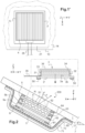
- FIG 1 is a front view on the exterior side of a rear window 1000 with two OLED examples with collimated light redirected according to the invention, therefore in the direction of the exterior face F1 11 of the first sheet of glass, for example monolithic 1.
- the OLEDs are powered by a connector 35 protruding from the edge of the glass and optionally the latter is masked from the outside by a peripheral masking layer, in particular black enamel (not shown) on face F2.
- a peripheral masking layer in particular black enamel (not shown) on face F2.
- the OLEDS as a variant can form a pictogram .
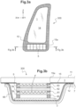
- FIG. 1a is a front detail view of the OLED 3 (one or more contiguous or separate OLEDs, for example each rectangular) provided on the exit surface 30' side with its collimating optics in a network of prisms extending along the horizontal H surmounted by that of redirection 5 in a network of asymmetrical prisms extending along the horizontal H.
- the OLED 3 one or more contiguous or separate OLEDs, for example each rectangular
- FIG. 1' a is an alternative front detail view of several OLEDs 3 placed side by side (for example each square or rectangular) provided with their collimation and redirection optics 5. Between the OLEDs the optics (non-functional parts 55') can be of reduced width or even zero or no texturing.
- One or more transparent and thin optical films for example of rectangular shape (constant or reduced width between the OLEDs as already stated), in particular a stack of two or three or more films, are also preferred for each lens.
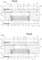
- FIG 1i is an overview of a collimating optic according to the invention.
- FIG 1X is a cross-sectional view of the collimation optics with pointed vertices S and the representative angles of the prisms (angle at the vertex, angle with plane of the prismatic optical film).
- the collimation optic 5a is here a prismatic optical film which will be for example fixed at the periphery by a double-sided adhesive or glue to the exit surface (generating an air gap at the entrance) of the OLED. It is for example a plastic film, for example, less than 0.3 mm thick and made of PET that is partially textured in thickness. It comprises on the front face a network of prisms 50 preferably contiguous and even symmetrical with vertices S and with a pitch T between vertices which is from 10 ⁇ m to 500 ⁇ m extending longitudinally along an axis forming an angle of at most 10° with the reference direction (here the horizontal for the bezel or alternatively a windshield) and even parallel.
- Each prism is defined by two longitudinal faces 41,42 each prism has an apex angle ranging from 60 to 110°, better still 90° and each longitudinal face forms with the plane of the optical film 4 an angle ranging from 30 to 55° better of 45°.
- the pitch is 160 ⁇ m and the height 80 ⁇ m and the remaining thickness is 175 ⁇ m with an angle at the top and on the valley side of 90° (+-20 arc).
- Air is between the output surface of the OLED and the input face of this single optical film 5a of the collimating optics.
- Air is between the prisms of the front face of the collimation optics, the tops of the patterns of each front face are in physical contact with the face F2.
- FIG. 1' is a front detail view on the outside of the OLED with the collimation and redirection optics 5 glued on the periphery, for example facing the technical edges (on the support 3') of the OLED 3.
- the longitudinal axis of the prisms is the horizontal between the sides of the telescope (or the windshield).
- the bonding can be framed and form a seal.
- FIG. 1Y is an overview of another collimating optic 4 according to the invention. This figure differs from the figure 1X in that the vertices are rounded and the side faces curved, the angles representative of the prisms are defined (angle at the vertex, angle with the plane of the film) from the two secant straight lines b1, b2 at A passing through the points of inflection I1 ,I2. The radius of curvature is also limited.
- FIG. 1j is an overview of a collimating optic according to the invention.
- This figure differs from 1i in that to form the collimating optics, a second identical prismatic film 5b is added and crossed at 90° and for example glued (welded, etc.) at the periphery to the first prismatic film 5a.
- collimating optics 4 (always a textured plastic film partially in thickness, for example in PET and less than 0.6 mm) bears two-dimensional patterns.
- Each two-dimensional pattern being defined by a side e in a plane P normal to the film 5a, the two-dimensional pattern has an apex angle ranging from 60 to 110°, each intersection of the side with the plane P forming with the plane of the film an angle ranging from 30 to 55°. Preferably one chooses angle at the top (in the plane P) of 90° and the 2 other angles of 45°.
- the two-dimensional patterns are here in relief, the tops of the patterns of each front face are free or in physical contact with a transparent element (face F2 of the exterior glazing for example), air is between the two-dimensional patterns.
- the two-dimensional patterns are hollow
- the network of two-dimensional patterns is a network of cavities
- the vertices S are oriented (towards the interior of the passenger compartment (towards the face F3 laminated glazing) and the upper surface of each cavity is free or in physical contact with a transparent element (second glazing, etc.), air is in the cavities.
- FIG 1Z is a front view of a redirection optic which will be on the front face of the collimation optic (fixed at the periphery, for example glued or welded or spaced apart by at most 1mm). It is an optical redirection film comprising an array of asymmetrical prisms with vertices and with a pitch T' between vertices which is from 10 ⁇ m to 500 ⁇ m, preferably with at least 4 or even 10 patterns facing the exit surface ( or emitting light),
- the redirection optics thus comprises a first optical film 5 which is asymmetric prismatic with, on a main face opposite the exit surface called the final front face, said network of asymmetric prisms extending longitudinally along a third axis forming an angle of at most 10°, at most 5° or at most 2° with said first axis and even parallel and/or with the reference direction of the glazing (the horizontal for the bezel) and even is parallel, in particular with a sub-millimeter thickness.
- Each asymmetrical prism is defined by first and second longitudinal faces, the prism preferably having a length L and a width W with L>2W and better still L>5W or L>10W.
- Each asymmetrical prism has an apex angle a'0 ranging from 50 to 60°, better 55° ⁇ 5°, 55° ⁇ 2° and the first longitudinal face 51 (known as the long side) forms a first angle with the plane of the film, ranging from 31 to 41° better than 35° ⁇ 5°, 35° ⁇ 2° (naturally the second longitudinal face (known as the short side) 52 forms a second angle with the plane of the film, ranging from 79 to 99° better than 85 at 90°, 88 to 90° preferably at most 90°
- the difference a4-a3 is greater than 40° and even 50°
- a set of two parallel optical films which are prismatic is even chosen asymmetrical.
- FIG 2 is a cross-sectional view of a monolithic rear window (bezel) with redirected collimated light OLED according to the invention according to one embodiment.
- This bezel 200 comprises a first transparent glazing 1 in mineral or organic glass, with main faces 11, 12 called faces F1 and F2, and an edge (0, and a so-called reference direction which is horizontal to the plane of the glazing ( domed or not).
- OLED 3 emits auto red towards face F2 and has an emitting surface with a length of at least 5cm and a width of at least 1cm, and is preferably of sub-millimeter thickness E0, with a half angle of emission at the top of 50° to 70° and a main emission direction normal to the plane of said OLED.
- this first film On the front face of this first film is fixed by peripheral gluing 62 a second optical film 5b with the second network of prisms extending longitudinally along a second axis forming an angle with said first axis of 90°, the first or the second axis forms a zero angle with the reference direction.
- a first optical redirection film 5 with an array of asymmetrical prisms with a long side 51 and a short side 52 extending longitudinally in the direction of reference
- the normal N to the large side directed towards the face F2 is oriented towards the top of the rear window or the windshield (for a redirection towards the ground).
- This redirection film is fixed by peripheral gluing 64 (glue, double face, etc.) to face F2 (or F4 if laminated) which is optional because here a rear protective film 7 (here two-layer 70, 71 covers and overflows the OLED and optical assembly 5a, 5b, 5 with glue 65. its main faces.
- the telescope is for example oriented between 12° and 80° from the ground and for example from 50 to 70°.
- the film bends the light at an angle of at least 15° towards the ground.
- the OLED 3 comprises a connector 35 protruding from the edge of the first glazing here fixed on the input surface side at the periphery
- the OLED 3 is rear-emitting comprising a support 3', which carries the side opposite the face F2 in this order, moving away from the support: a possible functional sub-layer 31, a transparent anode 32, an electroluminescent system organic material 33, a reflective cathode 34 and an encapsulation (resin) layer 36.
- FIG. 3a is a front view of a monolithic deflector 300 (side fixed window) with redirected collimated light OLED according to the invention.
- FIG. 3b is a cross-sectional view of the deflector (fixed side window) with redirected collimated light OLED according to the invention.
- This deflector comprises a first transparent glazing 1 in mineral or organic glass, with main faces 11, 12 called faces F1 and F2, and an edge 10, and a so-called reference direction which is normal to the horizontal plane of the glazing. (bulging or not). It is for example in the shape of a quadrilateral with an upper edge of reduced width. It comprises a masking layer 15 (black enamel, etc.) for example on face F2 and provided with a spare 15a.
- the OLED 3 is opposite the savings 15a and on the inside and emits auto yellow towards the face F2 and has an emitting surface with a length of at least 5cm and a width of at least 1cm, and is preferably d submillimeter thickness E0, with a half emission angle at the top of 50° to 70° and a main emission direction normal to the plane of said OLED.
- it is a rectangular light strip (or any other shape) at the bottom border.
- this first film On the front face of this first film is fixed by peripheral gluing 61 a second optical film 5b with the second array of prisms extending longitudinally along a second axis forming an angle with said first axis of 90°, the first or the second axis forms a zero angle with the reference direction.
- a first optical redirection film 5 with an array of asymmetrical prisms with a long side 51 and a short side 52 extending longitudinally in the reference direction.
- the normal N to the large side directed towards the face F2 is oriented towards the front of the deflector (for a rearward redirection.
- This redirection film is fixed by peripheral bonding 64 to face F2, which is optional because here a protective rear film 7 (here two-layer 70,71 covers and overflows the OLED and optical assembly 5a, 5b, 5 film with glue 65.
- a protective rear film 7 here two-layer 70,71 covers and overflows the OLED and optical assembly 5a, 5b, 5 film with glue 65.
- it is tinted or carries an electrically conductive functional layer 71 (solar control, etc.)
- the telescope is for example oriented between 12° and 80° from the ground and for example from 50 to 70°.
- the film bends the light at an angle of at least 15° towards the ground.
- the OLED 3 comprises a connector 35 protruding from the edge of the first glazing here fixed on the input surface side at the periphery.
- the enamel can be in front F2 and in F3 or F4 (each with a reserve).
- FIG. 3c is a front detail view of the OLED 3 provided with its collimation optics in an array of prisms extending along the horizontal H and that of redirection 5 in an array of asymmetrical prisms extending along the vertical on the surface side exit 30'.
- FIG. 3b is an alternative front detail view of several OLEDs 3 joined together provided with their collimation and redirection optics 5 between the oleds the optics (non-functional) can be of reduced width or even equal to zero or without texturing.
- FIG. 4a is a sectional view of a glazing 400a (bezel or deflector or windshield) with collimated and redirected light according to the invention.
- an electroluminescent element which is an OLED 3, (or OLED or a TFEL) and capable of emitting auto red light to form a brake light or other light (or auto yellow for turn signal repeater) or serves for external signage (pictogram, etc.) towards face F2 12, OLED having an output surface 30 towards face F2 and an opposite input surface 30 in the bottom of opening 2a.
- the OLED comprises a connector 35 protruding from the edge of the first glazing here fixed on the input surface side at the periphery.
- the OLED is rear-emitting, for example.
- a holographic redirection optic having a rear face on the output surface side and a front face opposite the rear face.
- the emerging opening 2a surrounds the OLED 4, the optics 4.5 and even in contact with its edge or, as a variant, spaced apart by at most 0.5 mm and even by at most 0.1 mm from the edge.
- a first sheet 21 is chosen, made of PVB, with a through opening (or blind as a variant) and a second rear sheet of PVB 22 on the rear face side 30.
- the two sheets are joined with or without a discernible interface (here in dotted lines).
- the OLED 3 is prefixed to the rear sheet 22 by gluing 60 or by placing in point adhesive contact by point heating (and pressure).
- the two sheets 21, 22 can be placed in point adhesive contact outside the zone of the OLED 3 before or after the installation between the two panes 1, 1'.
- the collimating optics 4 is here a prismatic optical film or preferably with two-dimensional patterns (especially if single) fixed at the periphery by a double-sided adhesive or a glue 60 to the exit surface (generating an air gap at the entrance ). It is for example a partially textured plastic film with a thickness of less than 0.3 mm for example and made of PET. For example the pitch is 160 ⁇ m and the height 80 ⁇ m and the remaining thickness is 175 ⁇ m with angle at the top and valley side of 90° (+-20 arc). Air is between the exit surface and the entry face of this first single optical film of the collimating optics. Air is between the patterns (prisms etc) of the front face of the collimating optics 4, the tops of the patterns are in physical contact with the redirection optics 5.
- the redirection optic 5 is here an asymmetrical prismatic optical film against or preferably as here fixed at the periphery by a double-sided adhesive or glue 60 to the front face of the optic 4 (generating an air gap at the inlet of the redirection optics 5) and preferably against or as here fixed at the periphery by a double-sided adhesive or a glue 60 to the face F2 (generating an air gap at the outlet). Air is between the prisms of the front face of the redirection optics, the tops of the patterns are possibly in physical contact with the face F2 12.
- the stack of the two films 4, 5 can be very thin.
- FIG. 4b is a sectional view of a glazing 400b (bezel or deflector or windshield) with collimated and redirected light according to the invention.
- This figure differs from the figure 4a in that the collimation optics 4 and that of redirection 5 are wider than the OLED 3 and than the emerging opening (than the through opening of the second sheet 21) and is here fixed (or against) on the face PVB 21 by gluing 62 or before lamination by bringing adhesive into point contact by point heating (and pressure).
- the redirection optic 5 is here an asymmetric prismatic optical film against or preferably as here fixed at the periphery by a double-sided adhesive or glue 60 to the front face of the optic 4 (generating an air gap at the inlet ) and preferably against or as here fixed at the periphery by a double-sided adhesive or a glue 60 to the face F2 12. Air is between the prisms of the front face of the redirection optics, the tops of the patterns are possibly in physical contact with face F2.
- FIG. 4c is a sectional view of a glazing 400c (bezel or deflector or windshield) with collimated and redirected light according to the invention.
- This figure differs from the previous one in that the collimation optics 4 and the redirection optics 5, still in the emerging opening, are wider than the OLED 3 and the collimation optics 4 are glued together 61 to PVB 22 (front face of rear PVB sheet 22) with or without spacer aid.
- the redirection optic 5, is against or as here fixed at the periphery by a double-sided adhesive or a glue 60 to the face F2 12.
- FIG. 400d is a sectional view of a glazing 400d (bezel or deflector or windshield) with collimated and redirected light according to the invention.
- This figure differs from the figure 4a in that the opening in the PVB is internal.
- a front PVB sheet 23 was placed on sheet 21 with opening (became central sheet).
- This film 7 can be a colored filter (white OLED and red or yellow filter etc).
- the redirection optic 5, here is an asymmetric prismatic optical film against or as here fixed at the periphery by a double-sided adhesive or glue 60 to the plastic protective film 7.
- FIG. 4e is a sectional view of a glazing 400e (bezel or deflector or windshield) with collimated and redirected light according to the invention.
- the plastic protective film 7 is a film covering, for example, less than 0.3 mm and made of PET which is glued to the periphery of the front face of the prismatic optical film 5 for redirection and/or simply covers (closes) the through-hole. It is in adhesive contact with the front PVB 23, for example preassembled with (functional PET/front PVB together before lamination) and with the PVB 21 (outside the opening area).
- This film 7.71 can be tinted and/or have an electrically conductive functional coating 72 on the face side F2 or F3: solar control, low E, etc.
- the redirection optic 5, here is an asymmetric prismatic optical film against or as here fixed at the periphery by a double-sided adhesive or glue 60 to the plastic protective film 7.
- FIG. 5 is a cross-sectional view of a glazing 500 (bezel or deflector or windshield) with redirected collimated light OLED according to the invention.
- This figure differs from the 4d figure in that a second identical prismatic film 4' is added crossed at 90° and glued (welded, etc.) at the periphery 61 to the first prismatic film and to the redirection film 5.
- the redirection optic 5, here is an asymmetric prismatic optical film against or as here fixed at the periphery by a double-sided adhesive or glue 60 to the plastic protective film 7.
- FIG. 6a is a cross-sectional view of a glazing 600a (bezel or deflector or windshield) with OLED with redirected collimated light according to the invention.
- This figure differs from the figure 4a in that the collimating optics 4 (always a textured plastic film, for example PET and less than 0.6 mm) carries two-dimensional patterns.
- the collimating optics 4 (always a textured plastic film, for example PET and less than 0.6 mm) carries two-dimensional patterns.
- Each two-dimensional pattern being defined by a side and, in a plane P normal to the film, the two-dimensional pattern has an apex angle ranging from 60 to 110°, each intersection of the side with the plane P forming with the plane of the film an angle ranging from 30 to 55°.
- the apex angle (in the plane P) of 90° and the other angles of 45° are chosen.
- the redirection optic 5 is here an asymmetrical prismatic optical film against or as here fixed at the periphery by a double-sided adhesive or glue 60 to the face F2.
- FIG. 6b is a sectional view of a glazing 600b with redirected collimated light OLED according to the invention.
- This figure differs from the figure 6a in that the collimating optics 4 is glued to a spacer frame 163a surrounding the OLED 3 for example against or glued to the rear PVB 22.
- FIG. 7a is a view showing an assembly step outside lamination of the OLED 3 with the collimation optics 4 and that of redirection 5 on a first interlayer PVB sheet of lamination 22 with the aim of producing the vehicle glazing according to the invention.
- the collimation optics (a prismatic film or two films crossed or with 2D patterns) is premounted on the OLED 3 by peripheral bonding as well as the redirection optics 5 on the collimation optics.
- a second sheet 21 is used with a through opening housing the assembly with the connector 35 protruding (on the input surface side of the OLED 3).
- the whole is placed on the back sheet 22 (face 22b) with possible local adhesive contact by heating and/or roller pressure) between PVB 21 and PVB 22 outside the OLED zone or between OLED and PVB 22 and/or between the connector and the PVBs 21, 22.
- the perforated sheet is first placed and it is lifted to place the OLED and optical assembly in the marked zone or zones.
- a third PVB sheet is added on the exit surface side (front PVB) it is necessary to use a local protective film or cover between the redirection optics and the rear face of this front PVB sheet.
- a transparent thin plastic film and even colored and white OLED
- a functional layer is added.
- FIG. 7b is a view showing an assembly step outside the lamination of the OLED with the collimation and redirection optics on a first interlayer PVB lamination sheet for the purpose of producing the glazing according to the invention.
- This figure differs from the previous one in that the rear surface of the OLED is fixed by gluing 60 to the rear sheet 22.
- a third PVB sheet is added on the output surface side (front PVB) it is necessary to use a local or covering protective film between the redirection optics 5 and the rear face of this front PVB sheet. For example, a transparent thin plastic film and even a functional layer is added.
- FIG. 7c is a view showing an assembly step outside the lamination of the OLED with the collimation and redirection optics on a first interlayer PVB lamination sheet for the purpose of producing the glazing according to the invention.
- An aid to the positioning of the OLED is provided by a film 90 with a mark 91 either non-stick against the face 22a or opposite the transparent table (glass) for laminating.
- a third PVB sheet is added on the output surface side (front PVB) it is necessary to use a local or covering protective film between the redirection optics 5 and the rear face of this front PVB sheet.
- a local or covering protective film between the redirection optics 5 and the rear face of this front PVB sheet.
- it is a transparent thin plastic film and even functional layer.
- FIG. 7d is a view showing an assembly step outside the lamination of the OLED with the collimation and redirection optics on a first interlayer PVB lamination sheet for the purpose of producing the glazing according to the invention.
- This figure differs from the figure 7a in that the collimating optic 4 and that of redirection 5 are wider than the through hole 25 of the PVB 21 and the collimating optic 4 is fixed against the front face of the perforated PVB sheet 21 by gluing or, as a variant, by placing in adhesive contact (heating and/or pressure). Optics 4 closes the hole and is spaced from OLED 3.
- a third PVB sheet is added on the exit surface side (front PVB) it is necessary to use a local protective film or cover between the redirection optics and the rear face of this front PVB sheet.
- a local protective film or cover between the redirection optics and the rear face of this front PVB sheet.
- it is a transparent thin plastic film and even functional layer.
- FIG. 7e is a view showing an assembly step outside the lamination of the OLED with the collimation and redirection optics on a first interlayer PVB lamination sheet for the purpose of producing the glazing according to the invention.
- This figure differs from the figure 7c in that the collimating optic 4 wider than the OLED is fixed against the front face of the rear sheet 22 by gluing 52 with or without a spacer.
- a third PVB sheet is added on the exit surface side (front PVB) it is necessary to use a local or covering protective film between the redirection optics 5 and the face back of this front PVB slip.
- a local or covering protective film between the redirection optics 5 and the face back of this front PVB slip.
- it is a transparent thin plastic film and even functional layer.
- FIG. 7f is a view showing an assembly step outside the lamination of the OLED with the collimation and redirection optics on a first interlayer PVB lamination sheet for the purpose of producing the glazing according to the invention.
- This figure differs from the figure 7b in that the second PVB sheet 23 comprises a blind opening 25, the redirection optic 5 is protected from the bottom by a local protective plastic film in the opening.
- FIG. 7g is a view showing an assembly step outside the lamination of the OLED with the collimation and redirection optics on a first interlayer PVB lamination sheet for the purpose of producing the glazing according to the invention.
- This figure differs from the figure 7f in that the protective film is glued to the bottom by gluing or bringing into local adhesive contact (heating and/or pressure).
Description
L'invention concerne un vitrage de véhicule à signalisation lumineuse externe ainsi qu'un véhicule comportant un tel vitrage et la fabrication d'un tel vitrage.The invention relates to a vehicle glazing with external light signaling as well as a vehicle comprising such glazing and the manufacture of such glazing.
Il existe de plus en plus un vitrage de véhicule à signalisation lumineuse externe, par exemple
En particulier il est commun de placer en face interne dite F2 un bloc lumière pour former un 3eme feu stop.In particular, it is common to place a light block on the internal face called F2 to form a 3rd brake light.
L'intégration peut être améliorée ainsi que le procédé de fabrication.The integration can be improved as well as the manufacturing process.
A cet effet, la présente demande a pour premier objet un vitrage de véhicule à signalisation lumineuse externe, choisie parmi une vitre arrière (lunette) et une vitre latérale (de préférence fixe, déflecteur) ou un parebrise, notamment automobile ou encore de transport en commun comprenant :
- un premier vitrage transparent, en verre minéral notamment trempé (thermiquement ou chimiquement) ou organique, éventuellement clair, extraclair, de préférence bombé, destiné à être le vitrage extérieur, avec des première et deuxième faces principales respectivement dites face F1 (face extérieure du véhicule) et face F2, et pour le véhicule automobile, en particulier vitrage en verre minéral ou organique d'épaisseur de préférence d'au plus 2,5mm, même d'au plus 2,2mm - notamment 1,9mm, 1,8mm, 1,6mm et 1,4mm- ou même d'au plus1,3mm ou d'au plus 1mm, avec de préférence une direction de référence,
- une source de lumière, qui est un élément électroluminescent, côté face F2 et apte à émettre de la lumière de signalisation externe (donc vers la face F2) - choisie à façon selon les normes, par exemple l'ambre ou le jaune (auto) pour un répétiteur de clignotant ou encore le rouge (auto) pour un (3eme) feu (stop)-, source de lumière ayant une surface de sortie vers la face F2 (et une surface d'entrée à l'opposé), et avec un demi angle d'émission au sommet de 50° à 70°, notamment 55 à 65°, et une direction d'émission principale normale au plan dudit élément électroluminescent, et même normale au plan (moyen) du vitrage (de
préférence 90±5°,90±2° et même de 90°) - l'élément électroluminescent, notamment transparent, a une surface émettrice de lumière de longueur d'au moins 5cm mieux d'au moins 10cm et même une largeur d'au moins 1cm ou 2cm mieux d'au moins 5cm et de préférence est d'épaisseur E0 subcentrimétrique et mieux submillimétrique.
- a first transparent glazing, in mineral glass in particular toughened (thermally or chemically) or organic, optionally clear, extra-clear, preferably curved, intended to be the exterior glazing, with first and second main faces respectively called face F1 (outer face of the vehicle ) and face F2, and for the motor vehicle, in particular glazing in mineral or organic glass with a thickness of preferably at most 2.5 mm, even at most 2.2 mm - in particular 1.9 mm, 1.8 mm, 1.6mm and 1.4mm - or even at most 1.3mm or at most 1mm, preferably with a reference direction,
- a light source, which is an electroluminescent element, face F2 side and capable of emitting external signaling light (therefore towards face F2) - chosen according to standards, for example amber or yellow (auto) for a turn signal repeater or even red (auto) for a (3rd) (stop) light -, light source having an exit surface towards face F2 (and an entry surface on the opposite side), and with a half emission angle at the top of 50° to 70°, in particular 55 to 65°, and a main emission direction normal to the plane of said electroluminescent element, and even normal to the (average) plane of the glazing (preferably 90 ± 5°,90±2° and even 90°)
- the electroluminescent element, in particular transparent, has a light-emitting surface with a length of at least 5cm, better still at least 10cm and even a width of at least 1cm or 2cm, better still at least 5cm and preferably is of thickness E0 subcentrimetric and better still submillimetric.
De préférence, dans une (première) configuration, le vitrage comporte en regard dudit élément électroluminescent, entre la face F2 et ledit élément électroluminescent, une optique de collimation, ayant une face arrière côté surface de sortie et une face avant dite de collimation opposée à la face arrière.Preferably, in a (first) configuration, the glazing comprises facing said light-emitting element, between face F2 and said light-emitting element, collimation optics, having a rear face on the exit surface side and a so-called collimation front face opposite the rear face.
L'optique de collimation, en matière transparente de préférence plastique (notamment thermoplastique, poly(éthylène téréphtalate) PET, poly(naphtalate d'éthylène) PEN, polyéthylène PE, poly(méthacrylate de méthyle) PMMA, polydiméthylsiloxane PDMS polyamide, polyimide, polyacrylate, polyester, polycarbonate, polysulfones, polyéthersulfones, thermoplastique polyuréthane) et/ou même flexible, est de préférence d'épaisseur (totale) E1 submillimétrique, mieux d'au plus 0,6mm ou 0,3mm ou 0,15mm. L'optique de collimation comporte, et même est, un film optique de préférence plastique (notamment thermoplastique, PET, PE, PC, PMMA, PDMS), notamment film partiellement texturé dans son épaisseur, ou en alternative film composite comportant un support transparent (plastique notamment comme précité) lisse avec une surcouche transparente texturée partiellement ou entièrement en épaisseur) ou un ensemble de films optiques de préférence plastiques (notamment comme précité), chacun comportant un réseau de motifs avec des sommets S et avec un pas T entre sommets qui est de 10µm à 500µm de préférence, avec de préférence au moins 4 ou même 10 motifs en regard de la surface de sortie (ou émettrice de lumière).The collimating optics, made of transparent material, preferably plastic (in particular thermoplastic, poly(ethylene terephthalate) PET, poly(ethylene naphthalate) PEN, polyethylene PE, poly(methyl methacrylate) PMMA, polydimethylsiloxane PDMS polyamide, polyimide, polyacrylate , polyester, polycarbonate, polysulfones, polyethersulfones, thermoplastic polyurethane) and/or even flexible, is preferably of (total) thickness E1 submillimeter, better still at most 0.6 mm or 0.3 mm or 0.15 mm. The collimation optic comprises, and even is, an optical film, preferably plastic (in particular thermoplastic, PET, PE, PC, PMMA, PDMS), in particular a film partially textured in its thickness, or as an alternative composite film comprising a transparent support ( plastic in particular as mentioned above) smooth with a transparent overlayer textured partially or entirely in thickness) or a set of preferably plastic optical films (in particular as mentioned above), each comprising a network of patterns with vertices S and with a pitch T between vertices which is from 10 μm to 500 μm preferably, with preferably at least 4 or even 10 patterns opposite the exit (or light-emitting) surface.
L'optique de collimation selon l'invention comporte ainsi :
- a) un premier film optique et de préférence unique, avec sur la face avant dite de collimation ledit réseau de motifs bidimensionnels (vers la face F2), notamment un film texturé avec ledit réseau, notamment avec une épaisseur d'au plus 0,3mm ou 0,2mm ou 0,15mm
- b) ou un ensemble d'au moins deux films optiques qui sont prismatiques, de préférence d'au plus deux films optiques prismatiques, comportant dans cet ordre en s'éloignant de la surface de sortie:
- un premier film optique avec sur une face principale opposée à la surface de sortie, (dite face intermédiaire), un premier réseau de prismes (motifs prismatiques) ou, notamment un premier film texturé avec ledit premier réseau, s'étendant longitudinalement (suivant leur longueur) suivant un premier axe, notamment avec une épaisseur submillimétrique et même d'au plus 0,3mm ou 0,2mm ou 0,15mm
- et en regard du premier film optique (de préférence espacé d'au plus 1mm ou fixé en périphérie par exemple collé ou soudé) un deuxième film optique avec sur une face principale opposée à la surface de sortie (de préférence formant ladite face avant) un deuxième réseau de motifs prismatiques, notamment un film texturé avec ledit deuxième réseau, -croisé avec le premier réseau de motifs prismatiques-, le deuxième réseau de prismes (motifs prismatiques) s'étendant longitudinalement suivant un deuxième axe formant un angle avec ledit premier axe de 90±10°, de
préférence 90±5°,90±2° et même de 90°, le premier ou le deuxième axe forme avec la direction de référence un angle d'au plus 10°, mieux d'au plus 5° et même d'au plus 2°; et même est parallèle (angle à 0°), notamment avec une épaisseur submillimétrique et même d'au plus 0,3mm ou 0,2mm ou 0,15mm
- c) ou un premier film optique unique avec sur la face avant dite de collimation un premier réseau de prismes (motifs prismatiques), notamment un film texturé avec ledit premier réseau, s'étendant longitudinalement suivant un axe formant un angle d'au plus 10° mieux d'au plus 5° et même d'au plus 2° avec la direction de référence et même parallèle, notamment avec une épaisseur submillimétrique et même E0 d'au plus 0,3mm ou 0,2mm ou 0,15mm.
- a) a first and preferably single optical film, with said grating of two-dimensional patterns on the so-called collimation front face (towards face F2), in particular a film textured with said grating, in particular with a thickness of at most 0.3 mm or 0.2mm or 0.15mm
- b) or an assembly of at least two optical films which are prismatic, preferably of at most two prismatic optical films, comprising in this order away from the exit surface:
- a first optical film with, on a main face opposite the exit surface, (known as the intermediate face), a first array of prisms (prismatic patterns) or, in particular, a first film textured with said first array, extending longitudinally (along their length) along a first axis, in particular with a sub-millimeter thickness and even at most 0.3mm or 0.2mm or 0.15mm
- and facing the first optical film (preferably spaced by at most 1 mm or fixed at the periphery, for example glued or welded) a second optical film with on a main face opposite the exit surface (preferably forming said front face) a second network of prismatic patterns, in particular a textured film with said second network, -crossed with the first network of prismatic patterns-, the second array of prisms (prismatic patterns) extending longitudinally along a second axis forming an angle with said first axis of 90±10°, preferably 90±5°, 90±2° and even 90°, the first or the second axis forms with the reference direction an angle of at most 10°, better still of at most 5° and even of at most 2°; and even is parallel (angle at 0°), in particular with a sub-millimeter thickness and even at most 0.3mm or 0.2mm or 0.15mm
- c) or a single first optical film with, on the so-called collimating front face, a first grating of prisms (prismatic patterns), in particular a film textured with said first grating, extending longitudinally along an axis forming an angle of at most 10 ° better by at most 5° and even by at most 2° with the reference direction and even parallel, in particular with a sub-millimeter thickness and even E0 of at most 0.3 mm or 0.2 mm or 0.15 mm.
Pour b) et c) chaque prisme étant défini par deux faces longitudinales le prisme ayant de préférence une longueur L et une largeur W avec L>2W et mieux L>5W ou L>10W.For b) and c) each prism being defined by two longitudinal faces, the prism preferably having a length L and a width W with L>2W and better still L>5W or L>10W.
Chaque prisme présente un angle au sommet a0 allant de 60 à 110°. Et chaque face longitudinale forme un angle a1, a2 allant de 30 à 55°, mieux de 35° à 50°, même de 40° à 50° et même de 45°±5°, 45°±1 ou de 45° avec le plan du film, de préférence a1-a2 est inférieur à 5° et même à 2° (prismes dits symétriques). En particulier pour b) et c):
- tout ou partie des prismes étant pointus avec les deux faces longitudinales planes et sécantes au sommet S chaque prisme pointu étant défini par l' angle au sommet a0 allant de 60 à 110°, mieux de 70° à 110°, même de 80° à 100° et même de 90°±5°, 90°±2 ou de 90°, chaque face longitudinale forme un angle a1, a2 allant de 30 à 55°, mieux de 35° à 50°, même de 40° à 50° et même de 45°±5°, 45°±1 ou de 45° avec le plan du film, de préférence la différence entre lesdits angles (définis par les faces longitudinales) a1-a2 est inférieure à 10°, à 5° et même à 2° (prismes dits symétriques)
- tout ou partie des prismes étant arrondis avec les deux faces longitudinales (chacune courbe ou au moins en partie courbe éventuellement avec une partie plane puis courbe vers le sommet), dans un plan normal P au plan du film et normal audit axe du prisme, l'intersection entre le plan P et chaque prisme arrondi forme une section comportant deux courbes C1, C2 jointives au sommet S, on définit deux droites D1 et D2 passant par les points d'inflexion I1 et I2 des deux courbes C1, C2, chaque droite formant un angle a1, a 2 allant de 30 à 55°, mieux de 35° à 50°, même de 40° à 50° et même de 45°±5°, 45°±1 ou de 45° avec le plan du film , et de préférence la différence entre lesdits angles (définies par les droites D1 et D2) a1-a2 est inférieure à 10°, à 5° et même à 2° (prismes dits symétriques)
- chaque prisme arrondi étant défini par un cercle tangent au sommet S avec un rayon de courbure R1 compris entre T/10 et T/5 (ces droites D1 et D2 sont sécantes et forme un angle a0 (correspondant à l'angle au sommet) allant de 60 à 110°, mieux de 70° à 110°, même de 80° à 100° et même de 90°±5°, 90°±2 ou de 90°).
- pour a) chaque motif bidimensionnel étant défini par un flanc, notamment au moins 3 faces latérales sécantes, le motif bidimensionnel présente de préférence un rapport de forme longueur L sur largeur W supérieur ou égal à 1 et d'au plus 2, même d'au plus 1,5 ou d'au plus 1,1
- all or part of the prisms being pointed with the two flat and intersecting longitudinal faces at the vertex S, each pointed prism being defined by the vertex angle a0 ranging from 60 to 110°, better still from 70° to 110°, even from 80° to 100° and even 90°±5°, 90°±2 or 90°, each longitudinal face forms an angle a1, a2 ranging from 30 to 55°, better still from 35° to 50°, even from 40° to 50 ° and even 45°±5°, 45°±1 or 45° with the plane of the film, preferably the difference between the said angles (defined by the longitudinal faces) a1-a2 is less than 10°, less than 5° and even at 2° (so-called symmetrical prisms)
- all or part of the prisms being rounded with the two longitudinal faces (each curved or at least partly curved possibly with a flat part then curved towards the top), in a plane normal P to the plane of the film and normal to said axis of the prism, l intersection between the plane P and each rounded prism forms a section comprising two curves C1, C2 contiguous at the vertex S, two lines D1 and D2 are defined passing through the points of inflection I1 and I2 of the two curves C1, C2, each line forming an angle a1, a2 ranging from 30 to 55°, better still from 35° to 50°, even from 40° to 50° and even from 45°±5°, 45°±1 or from 45° with the plane of the film, and preferably the difference between the said angles (defined by the straight lines D1 and D2) a1-a2 is less than 10°, 5° and even 2° (so-called symmetrical prisms)
- each rounded prism being defined by a circle tangent to vertex S with a radius of curvature R1 between T/10 and T/5 (these straight lines D1 and D2 are secant and form an angle a0 (corresponding to the angle at the vertex) ranging from 60 to 110°, better from 70° to 110°, even from 80° to 100° and even from 90°±5°, 90°±2 or 90°).
- for a) each two-dimensional pattern being defined by a flank, in particular at least 3 intersecting lateral faces, the two-dimensional pattern preferably has a aspect ratio length L to width W greater than or equal to 1 and of at most 2, even of not more than 1.5 or not more than 1.1
Lorsque les prismes sont jointifs on définit des vallées -en pointe ou arrondies- avec les mêmes tolérances sur l'angle dans la vallée que l'angle au sommet déjà décrit et sur le rayon de courbure éventuel dans la vallée.When the prisms are contiguous, valleys - pointed or rounded - are defined with the same tolerances on the angle in the valley as the angle at the top already described and on the possible radius of curvature in the valley.
Pour a), dans un plan P normal au film, le motif bidimensionnel présente un angle a0 allant de 60 à 110°, mieux de 70° à 110°, même de 80° à 100° et même de 90°±5°, 90°±2° ou de 90°, chaque intersection du flanc avec le plan P formant avec le plan du film un angle a1, a2 allant de 30 à 55°, mieux de 35° à 50°, même de 40° à 50° et même de 45°±5°, 45°±1 ou de 45°, de préférence la différence entre lesdits angles (définies par les 2 intersections) a1-a2 est inférieure à 10° , à 5° et même à 2° (motifs dits « symétriques »). En particulier pour a) :
- tout ou partie des motifs bidimensionnels étant pointus, pour chaque motif bidimensionnel pointu l'intersection entre un plan P normal au film passant par le sommet S et le motif bidimensionnel pointu forme une section triangulaire comportant deux droites D1 et D2 sécantes au sommet S formant l'angle au sommet a0 allant de 60 à 110°, mieux de 70° à 110°, même de 80° à 100° et même de 90°±5°, 90°±2 ou de 90°,
- chaque droite D1, D2 formant avec le plan du film un angle a1, a2 allant de 30 à 55°, mieux de 35° à 50°, même de 40° à 50° et même de 45°±5°, 45°±1 ou de 45° avec le plan du film de préférence la différence entre lesdits angles a1-a2 est inférieur à 10°, à 5° et même à 2° (motifs dits « symétriques »)
- tout ou partie des motifs bidimensionnels étant arrondis pour chaque motif bidimensionnel arrondi l'intersection entre un plan P normal au plan du film passant par le sommet S forme une section comportant deux courbes C1, C2 jointives au sommet S', on définit deux droites D1 et D2 passant par les points d'inflexion I1 et I2 des deux courbes, formant chacune un angle a1, a2 allant de 30 à 55°, mieux de 35° à 50°, même de 40° à 50° et même de 45°±5°, 45°±1 ou de 45° avec le plan du film, et dans ledit plan P chaque prisme arrondi étant défini par un cercle tangent au sommet S avec un rayon de courbure R1 compris entre T/10 et T/5 (ces droites D1 et D2 sont sécantes forment ledit angle au sommet a0 allant de 60 à 110°, mieux de 70° à 110°, même de 80° à 100° et même de 90°±5°, 90°±2 ou de 90°).
- all or part of the two-dimensional patterns being pointed, for each pointed two-dimensional pattern the intersection between a plane P normal to the film passing through the vertex S and the pointed two-dimensional pattern forms a triangular section comprising two straight lines D1 and D2 secant at the vertex S forming the vertex angle a0 ranging from 60 to 110°, better still from 70° to 110°, even from 80° to 100° and even from 90°±5°, 90°±2 or 90°,
- each line D1, D2 forming with the plane of the film an angle a1, a2 ranging from 30 to 55°, better still from 35° to 50°, even from 40° to 50° and even from 45°±5°, 45°± 1 or 45° with the plane of the film preferably the difference between said angles a1-a2 is less than 10°, 5° and even 2° (so-called “symmetrical” patterns)
- all or part of the two-dimensional patterns being rounded for each rounded two-dimensional pattern the intersection between a plane P normal to the plane of the film passing through the vertex S forms a section comprising two curves C1, C2 contiguous to the vertex S', two straight lines D1 are defined and D2 passing through the points of inflection I1 and I2 of the two curves, each forming an angle a1, a2 ranging from 30 to 55°, better still 35° to 50°, even 40° to 50° and even 45°±5°, 45°±1 or 45° with the plane of the film, and in said plane P each rounded prism being defined by a tangent circle at the vertex S with a radius of curvature R1 comprised between T/10 and T/5 (these lines D1 and D2 are secant forming the said angle at the vertex a0 ranging from 60 to 110°, better still from 70° to 110°, even 80 ° to 100° and even 90°±5°, 90°±2 or 90°).
Dans ladite configuration, le vitrage comprend en outre en regard de l'optique de collimation, une optique de redirection (dite assymétrique), entre l'optique de collimation et la face F2, de préférence sur l'optique de collimation (fixée en périphérie, par exemple collée ou soudée ou espacée d'au plus 1mm), en matière transparente de préférence plastique (notamment thermoplastique, poly(éthylène téréphtalate) PET, poly(naphtalate d'éthylène) PEN, polyéthylène PE, poly(méthacrylate de méthyle) PMMA, polydiméthylsiloxane PDMS polyamide, polyimide, polyacrylate, polyester, polycarbonate, polysulfones, polyéthersulfones, thermoplastique polyuréthane, par exemple même matière que le (dernier) film optique de collimation ou les films de collimations), qui est de préférence d'épaisseur E'1 submillimétrique et même d'au plus 0,5mm ou 0,3mm, comporte un film optique de préférence plastique ou un ensemble de films optiques, de préférence plastiques, chacun comportant sur une face principale opposée à la surface de sortie un réseau de prismes assymétriques avec des sommets et avec un pas T' entre sommets qui est de 10µm à 500µm, de préférence avec au moins 4 ou même 10 motifs en regard de la surface de sortie (ou émettrice de lumière), l'optique de redirection comporte ainsi:
- i) un premier film optique qui est prismatique assymétrique avec ledit réseau de prismes assymétriques s'étendant longitudinalement suivant un troisième axe formant un angle d'au plus 10°, au plus 5° ou au plus 2° avec ledit premier axe et même parallèle et/ou avec la direction de référence du vitrage, notamment avec une épaisseur submillimétrique et même d'au plus 0,3mm ou 0,2mm ou 0,15mm
- j) ou un ensemble de deux films optiques qui sont prismatiques assymétriques, comportant dans cet ordre en s'éloignant de la surface de sortie:
- un premier film optique assymétrique avec un réseau de prismes assymétriques, s'étendant longitudinalement suivant un troisième axe, notamment avec une épaisseur submillimétrique et même d'au plus 0,3mm ou 0,2mm ou 0,15mm le troisième axe forme chacun un angle avec la direction de référence (et même le premier axe), d'au plus 10°, d'au plus 5° ou au plus 2° et même est parallèle (0°).
- et en regard du premier film optique assymétrique (de préférence espacé d'au plus 1mm ou fixé en périphérie par exemple collé ou soudé) un deuxième film optique notamment avec une épaisseur d'au plus 0,3mm ou 0,2mm ou 0,15mm , avec un deuxième réseau de motifs prismatiques -croisé avec le premier réseau de motifs prismatiques-, s'étendant longitudinalement suivant un quatrième axe formant un angle avec ledit troisième axe d'au plus 10°, de préférence d'au plus 5°, d'au plus 2° et même de 0° et/ou le quatrième axe forme un angle avec la direction de référence (et même le premier axe), d'au plus 10°, d'au plus 5° ou au plus 2° et même est parallèle (0°).
- i) a first optical film which is asymmetric prismatic with said array of asymmetric prisms extending longitudinally along a third axis forming an angle of at most 10°, at most 5° or at most 2° with said first axis and even parallel and/or with the reference direction of the glazing, in particular with a thickness of sub-millimetre and even of at most 0.3mm or 0.2mm or 0.15mm
- j) or a set of two optical films which are asymmetric prismatic, comprising in this order away from the exit surface:
- a first asymmetrical optical film with an array of asymmetrical prisms, extending longitudinally along a third axis, in particular with a sub-millimeter thickness and even of at most 0.3mm or 0.2mm or 0.15mm the third axis each forms an angle with the reference direction (and even the first axis), by at most 10°, by at most 5° or at most 2° and even is parallel (0°).
- and facing the first asymmetrical optical film (preferably spaced apart by at most 1 mm or fixed at the periphery, for example glued or welded) a second film optical in particular with a thickness of at most 0.3 mm or 0.2 mm or 0.15 mm, with a second network of prismatic patterns - crossed with the first network of prismatic patterns -, extending longitudinally along a fourth axis forming an angle with said third axis of at most 10°, preferably at most 5°, at most 2° and even 0° and/or the fourth axis forms an angle with the reference direction (and even the first axis), no more than 10°, no more than 5° or no more than 2° and even is parallel (0°).
Pour i) et j) chaque prisme assymétrique étant défini par des première et deuxième faces longitudinales le prisme ayant de préférence une longueur L et une largeur W avec L>2W et mieux L>5W ou L>10W .For i) and j) each asymmetrical prism being defined by first and second longitudinal faces, the prism preferably having a length L and a width W with L>2W and better still L>5W or L>10W.
Chaque prisme assymétrique présente un angle au sommet a'0 allant de 50 à 60° mieux 55°±5°, 55°±2° ° et la première face longitudinale (dit grand côté) forme avec le plan du film optique asymétrique un premier angle a3, allant de 31 à 41° mieux de 35°±5°, 35°±2°. Naturellement la deuxième face longitudinale (dit petit côté) forme de préférence avec le plan du film optique asymétrique un deuxième angle a4, allant de 79 à 99° ou 90° mieux de 85 à 90°, de 88 à 90°, de préférence d'au plus 90°. De préférence la différence a4-a3 est supérieure à 40° et même à 50°.Each asymmetrical prism has an apex angle a'0 ranging from 50 to 60° better 55°±5°, 55°±2° ° and the first longitudinal face (known as the long side) forms with the plane of the asymmetrical optical film a first angle a3, ranging from 31 to 41° better than 35°±5°, 35°±2°. Naturally, the second longitudinal face (known as the short side) preferably forms with the plane of the asymmetric optical film a second angle a4, ranging from 79 to 99° or 90°, better from 85 to 90°, from 88 to 90°, preferably d at most 90°. Preferably the difference a4-a3 is greater than 40° and even 50°.
En particulier pour i) et j) :
- tout ou partie des prismes assymétriques étant pointus avec les deux faces longitudinales planes et sécantes au sommet S1 chaque prisme pointu étant défini par ledit angle au sommet a'0
- tout ou partie des prismes asymétriques étant arrondis avec les deux faces longitudinales (chacune courbe ou au moins en partie courbe éventuellement avec une partie plane puis courbe vers le sommet), dans un plan normal P au plan du film et normal audit axe du prisme, l'intersection entre le plan P et chaque prisme arrondi forme une section comportant deux courbes C'1, C'2 jointives au sommet S1,
on définit des premier et deuxième droites D'1 et D'2 passant par les points d'inflexion I'1 et I'2 des deux courbes C'1, C'2, - une première droite D'1 formant ledit angle a3 avec le plan du film,
- une deuxième droite D'2 formant ledit angle a4 avec le plan du film,
- all or part of the asymmetrical prisms being pointed with the two flat and intersecting longitudinal faces at the vertex S1, each pointed prism being defined by the said vertex angle a'0
- all or part of the asymmetrical prisms being rounded with the two longitudinal faces (each curved or at least partly curved possibly with a flat part then curved towards the top), in a plane normal P to the plane of the film and normal to said axis of the prism, the intersection between the plane P and each rounded prism forms a section comprising two curves C'1, C'2 contiguous at the vertex S1,
we define first and second straight lines D'1 and D'2 passing through the points of inflection I'1 and I'2 of the two curves C'1, C'2, - a first straight line D'1 forming said angle a3 with the plane of the film,
- a second straight line D'2 forming said angle a4 with the plane of the film,
Lorsque les prismes assymétriques sont jointifs on définit des vallées -en pointe ou arrondi- avec les mêmes tolérances sur l'angle dans la vallée que l'angle au sommet déjà décrit et sur le rayon de courbure éventuel dans la vallée.When the asymmetrical prisms are contiguous, valleys - pointed or rounded - are defined with the same tolerances on the angle in the valley as the angle at the top already described and on the possible radius of curvature in the valley.
La normale au grand côté dirigée vers la face F2 est orientée vers le haut de la vitre arrière ou du pare brise ou vers l'avant de la vitre latérale.The normal to the large side directed towards face F2 is oriented towards the top of the rear window or the windscreen or towards the front of the side window.
En outre dans la (première) configuration:
- la direction de référence pour la vitre arrière ou le parebrise est l'horizontale dans le plan de la vitre ou du pare brise
- de l'air est entre la surface de sortie (lisse ou déjà texturée pour favoriser l'extraction de lumière comme un réseau lenticulaire etc) et la face d'entrée du premier film optique de l'optique de collimation ( face lisse, sans revêtement, sans texturation micrométrique...), notamment le premier film optique étant espacé de la surface de sortie de préférence d'au plus 1mm ou fixé en périphérie par exemple collé et avec un éventuel espaceur ou même soudée, éventuellement est en contact physique (non optique), éventuellement en contact physique avec la surface de sortie, par exemple espacé d'au plus 1mm
- pour b) et c) de l'air est entre les prismes de la face avant de l'optique de collimation, notamment les sommets des motifs sont espacées ou en contact physique avec un élément transparent (deuxième film éventuel ou film prismatique assymétrique)
- pour a) les motifs bidimensionnels sont en creux, le réseau de motifs bidimensionnels est un réseau de cavités (la paroi de chaque cavité formant le flanc notamment les faces latérales sécante jointives ou le flanc conique), les sommets S sont orientés à l'opposé de la face F2 et la surface haute de chaque cavité (en particulier définissant le contour de la base) est espacée ou en contact physique avec le (premier) film prismatique assymétrique ou les motifs bidimensionnels sont en reliefs orientés vers la face F2, les sommets des motifs de chaque face avant sont espacés ou en contact physique avec le (premier) film prismatique assymétrique, de l'air est entre les motifs bidimensionnels
- la face avant du dernier film prismatique assymétrique est espacée ou en contact physique avec un élément transparent distinct notamment d'épaisseur de préférence subcentimétrique (film de protection et/ou fonctionnel, un deuxième vitrage si vitrage feuilleté, face F4) et même d'au plus 0,3mm, 0,15 mm ou correspondant au premier vitrage (la face F2 du premier vitrage).
- the reference direction for the rear window or the windshield is the horizontal in the plane of the window or the windshield
- air is between the exit surface (smooth or already textured to promote light extraction such as a lenticular array etc) and the entry face of the first optical film of the collimation optics (smooth face, without coating , without micrometric texturing...), in particular the first optical film being spaced from the exit surface preferably by at most 1mm or fixed at the periphery, for example glued and with a possible spacer or even welded, possibly is in physical contact ( non-optical), possibly in physical contact with the exit surface, for example spaced apart by at most 1mm
- for b) and c) air is between the prisms of the front face of the collimation optics, in particular the tops of the patterns are spaced apart or in physical contact with a transparent element (possible second film or asymmetric prismatic film)
- for a) the two-dimensional patterns are hollow, the network of two-dimensional patterns is a network of cavities (the wall of each cavity forming the flank, in particular the contiguous secant lateral faces or the conical flank), the vertices S are oriented opposite of face F2 and the upper surface of each cavity (in particular defining the outline of the base) is spaced apart or in physical contact with the (first) asymmetrical prismatic film or the two-dimensional patterns are in relief oriented towards face F2, the vertices patterns of each front face are spaced or in physical contact with the asymmetric prismatic (first) film, air is between the two-dimensional patterns
- the front face of the last asymmetric prismatic film is spaced apart or in physical contact with a separate transparent element, in particular of preferably subcentimetric thickness (protective and/or functional film, a second glazing if laminated glazing, face F4) and even at plus 0.3mm, 0.15mm or corresponding to the first glazing (the face F2 of the first glazing).
Dans une (deuxième) configuration alternative à l'ensemble optique de collimation/ de redirection déjà décrite, le vitrage comporte en regard de la surface de sortie une optique de redirection holographique, notamment en matière transparente de préférence plastique notamment thermoplastique (de préférence en polyester, en poly(éthylène téréphtalate) PET, polyéthylène PE polycarbonate PC, poly(méthacrylate de méthyle) PMMA, polystyrène, polyamide, polydiméthylsiloxane PDMS, poly(naphtalate d'éthylène) PEN, polyimide, polyacrylate, polysulfone, polyéthersulfone, (thermoplastique) polyuréthane), de préférence sur la surface de sortie (fixée en périphérie, par exemple collée voire soudée ou espacée d'au plus 1mm), l'optique de redirection holographique comporte une face avant vers la face F2 et une face arrière opposée, l'optique de redirection holographique, comporte, mieux est, un film notamment plastique avec un réseau de motifs holographiques (unidimensionnels par exemple prismatiques) sur la face avant de préférence d'épaisseur submillimétrique et même d'au plus 0,3mm, 0,15mm.In a (second) alternative configuration to the collimation/redirection optical assembly already described, the glazing comprises, opposite the exit surface, a holographic redirection optic, in particular made of transparent material, preferably plastic, in particular thermoplastic (preferably polyester , poly(ethylene terephthalate) PET, polyethylene PE polycarbonate PC, poly(methyl methacrylate) PMMA, polystyrene, polyamide, polydimethylsiloxane PDMS, poly(ethylene naphthalate) PEN, polyimide, polyacrylate, polysulfone, polyethersulfone, (thermoplastic) polyurethane ), preferably on the exit surface (fixed at the periphery, for example glued or even welded or spaced apart by at most 1 mm), the holographic redirection optic comprises a front face towards the face F2 and an opposite rear face, the holographic redirection optics, comprises, better, a notably plastic film with a network of holographic patterns (one-dimensional, for example prismatic) on the front face, preferably of sub-millimeter thickness and even of at most 0.3 mm, 0.15 mm.
Et, dans cette (deuxième) configuration alternative de l'air est entre la surface de sortie et la face d'entrée de l'optique de redirection holographique, de l'air est entre les motifs holographiques de la face avant finale de l'optique de redirection holographique, la face avant du film de redirection holographique est espacée ou en contact physique avec un élément transparent distinct d'épaisseur de préférence subcentimétrique (film de protection et/ou fonctionnel, un deuxième vitrage si vitrage feuilleté, face F4) et même d'au plus 0,3mm, 0,15mm ou correspondant au premier vitrage.And, in this (second) alternate configuration air is between the exit surface and the entrance face of the holographic redirection optic, air is between the holographic patterns of the final front face of the holographic redirection optics, the front face of the holographic redirection film is spaced apart or in physical contact with a distinct transparent element of preferably subcentimetric thickness (protective and/or functional film, a second glazing if laminated glazing, face F4) and even at most 0.3mm, 0.15mm or corresponding to the first glazing.
En outre dans ces configurations :
- la direction de référence pour la vitre arrière ou le pare brise est l'horizontale dans le plan de la vitre arrière ou du pare brise (pour une redirection vers le sol)
- et la direction de référence pour la vitre latérale est la normale à l'horizontale dans le plan de la vitre pour une redirection vers l'arrière.
- the reference direction for the rear window or the windshield is the horizontal in the plane of the rear window or the windshield (for a redirection towards the ground)
- and the reference direction for the side window is the normal to the horizontal in the plane of the window for a rearward redirection.
Selon l'invention, pour garantir leur efficacité on évite tout matière même transparente (colle, intercalaire de feuilletage) entre les motifs de chaque film et notamment on crée un gap d'air entre la surface de sortie et la face d'entrée du premier film optique.According to the invention, to guarantee their effectiveness, any material, even transparent, is avoided (glue, lamination insert) between the patterns of each film and in particular an air gap is created between the exit surface and the entry face of the first optical film.
Un contact physique (film contre surface de sortie) est toléré mais on préfère une lame d'air (épaisseur mieux contrôlée, moins de risques de zones irisées) par une fixation périphérique (collage de préférence) avec ou sans espaceur.Physical contact (film against exit surface) is tolerated but an air gap is preferred (better controlled thickness, less risk of iridescent zones) by peripheral attachment (preferably bonding) with or without a spacer.
Selon l'invention, la (même chaque) fixation périphérique est de préférence entièrement hors (décalée, donc périphérique) de la surface émettrice de lumière. La largeur de la fixation peut être d'au plus 5mm.According to the invention, the (even each) peripheral attachment is preferably entirely outside (offset, therefore peripheral) of the light-emitting surface. The width of the fixing can be at most 5mm.
Le ou les films optiques selon l'invention sont, efficaces, simples à mettre en oeuvre et peuvent être minces avec une épaisseur totale d'au plus 1mm ou même 0,5mm.The optical film or films according to the invention are effective, simple to implement and can be thin with a total thickness of at most 1 mm or even 0.5 mm.
L'ensemble des films (collimation et redirection) peuvent former un empilement fixé en périphérie de la surface de sortie.All of the films (collimation and redirection) can form a stack fixed at the periphery of the exit surface.
L'ensemble élément électroluminescent, optique de collimation et optique redirection peut être plat, parallèle à la face F2, plaqué ou collé en périphérie contre la face F2 ou la face F4 d'un vitrage feuilleté. L'ensemble élément électroluminescent, optique redirection holographique peut être plat, parallèle à la face F2, plaqué ou collé en périphérie contre la face F2 ou la face F4 d'un vitrage feuilleté.The light-emitting element, collimating optics and redirection optics assembly can be flat, parallel to the face F2, plated or glued at the periphery against the face F2 or the face F4 of a laminated glazing. The electroluminescent element assembly, holographic redirection optics can be flat, parallel to the face F2, plated or glued at the periphery against the face F2 or the face F4 of a laminated glazing.
Cet ensemble peut être compact, d'épaisseur totale d'au plus 10mm ou d'au plus 5mm.This assembly can be compact, with a total thickness of at most 10mm or at most 5mm.
L'élément électroluminescent est une source (quasi) lambertienne. C'est une source étendue par opposition aux sources de type ponctuelles telles que des diodes électroluminescentes inorganiques dites DEL (ou LED en anglais).The electroluminescent element is a (quasi) Lambertian source. It is an extended source as opposed to point-type sources such as inorganic light-emitting diodes called LEDs.
L'élément électroluminescent comme OLED ou QLED peut avoir collé sur sa surface de sortie déjà un film avec un réseau lenticulaire ou équivalent pour extraire la lumière souvent appelé EEL pour 'external extraction layer' en anglais ou une surface de sortie texturée à cet effet.The light-emitting element such as OLED or QLED may already have a film bonded to its output surface with a lenticular grating or equivalent to extract the light, often called EEL for 'external extraction layer' in English, or a textured output surface for this purpose.
L'élément électroluminescent est de préférence une bande rectangulaire. De préférence la surface émettrice de lumière est une surface active unique ou est un ensemble de surfaces actives élémentaires de préférence de longueur au moins 1 ou 2cm agencées, espacées pour produire une lumière homogène sur une surface de préférence rectangulaire. La surface active unique est de préférence rectangulaire. Les surfaces actives élémentaires sont de préférence carrées ou rectangulaires.The light emitting element is preferably a rectangular strip. Preferably the light-emitting surface is a single active surface or is a set of elementary active surfaces preferably of length at least 1 or 2 cm arranged, spaced apart to produce homogeneous light on a preferably rectangular surface. The single active surface is preferably rectangular. The elementary active surfaces are preferably square or rectangular.
On préfère des motifs pointus avec des faces planes mais un défaut de fabrication peut conduire à des motifs ondulés (flanc courbe et sommet arrondi). Ces motifs sont acceptables tels que délimités selon l'invention.We prefer pointed patterns with flat faces but a manufacturing defect can lead to wavy patterns (curved side and rounded top). These patterns are acceptable as delimited according to the invention.
Naturellement on préfère pour b) ou c) former un ensemble de motifs prismatiques (prismes) unidimensionnels suivant l'axe longitudinal. Si, par des raisons de fabrication etc, le prisme unidimensionnel est divisé en morceaux dans le sens de la longueur alors les morceaux sont espacés d'une distance inférieure à <5L mieux à 10L ou à 20L.Naturally it is preferred for b) or c) to form a set of one-dimensional prismatic patterns (prisms) along the longitudinal axis. If, for reasons of manufacture etc, the one-dimensional prism is divided into pieces lengthwise then the pieces are spaced at a distance less than <5L better than 10L or 20L.
Les motifs (prismes ou bidimensionnels) sont le plus proche possible les uns des autres, et ont par exemple leurs bases distantes de moins de 1mm, et de préférence de moins de 0,5mm.The patterns (prisms or two-dimensional) are as close as possible to each other, and for example have their bases less than 1 mm apart, and preferably less than 0.5 mm.
De manière encore préférée, les prismes ou les motifs bidimensionnels et les prismes assymétriques sont jointifs ou essentiellement jointifs.Even more preferably, the two-dimensional prisms or patterns and the asymmetrical prisms are contiguous or essentially contiguous.
Des motifs (prismes etc) sont dit jointifs lorsqu'ils se touchent en au moins une partie de leur surface. On préfère que les motifs soient jointifs car ainsi ils sont plus nombreux, efficaces. Par exemple pour chaque film prismatique, on a un ensemble de motif prismatiques unidimensionnels suivant l'axe longitudinal, et jointifs par leurs bases.Patterns (prisms, etc.) are said to be contiguous when they touch at least part of their surface. It is preferred that the patterns be contiguous because in this way they are more numerous and effective. For example, for each prismatic film, there is a set of one-dimensional prismatic patterns along the longitudinal axis, and joined by their bases.
Certains motifs bidimensionnels ne permettent pas une jonction totale entre les motifs. C'est notamment le cas lorsque si les bases sont de cercles même se touchant, il reste une certaine surface entre les cercles n'appartenant pas aux motifs. Par jonction totale, on entend le fait que le contour de la base d'un motif fait également entièrement partie des contours de ses motifs voisins.Certain two-dimensional patterns do not allow a total junction between the patterns. This is particularly the case when, if the bases are circles even touching each other, there remains a certain surface between the circles which does not belong to the patterns. By total junction, it is meant that the contour of the base of a pattern is also entirely part of the contours of its neighboring patterns.
Certains motifs peuvent être totalement jointifs, de sorte que l'intégralité de la surface (au moins celle fonctionnelle en regard de l'élément électroluminescent) du film optique fasse partie d'au moins un motif. Il s'agit de motif de pavage. En particulier, des motifs bidimensionnels à base carrée ou rectangulaire ou hexagonale peuvent être totalement jointifs si électroluminescent les bases sont identiques. Dans le cas de bases carrées ou rectangulaires, il convient également que lesdites bases soient alignées pour que les motifs soient totalement jointifs. Dans le cas de bases hexagonales, il convient que lesdites bases forment un nid d'abeille.Some patterns can be completely contiguous, so that the entire surface (at least the functional one facing the light-emitting element) of the optical film forms part of at least one pattern. This is tessellation pattern. In particular, two-dimensional patterns with a square or rectangular or hexagonal base can be completely contiguous if the electroluminescent bases are identical. In the case of square or rectangular bases, said bases should also be aligned so that the patterns are completely contiguous. In the case of hexagonal bases, said bases should form a honeycomb.
Chaque film transparent texturé couvrant l'élément électroluminescent (l'OLED ou OLED de préférence) peut être texturé par région, donc porteur d'une ou des régions texturées, en vis-à-vis d'un élément électroluminescent (OLED ou OLED) ou de plusieurs élément électroluminescent (OLED ou OLED) et les régions adjacentes (décalés de l'OLED ou OLED) sont lisses (pour laisser de la transparence).Each textured transparent film covering the light-emitting element (OLED or OLED preferably) can be textured by region, therefore carrying one or more textured regions, facing a light-emitting element (OLED or OLED) or more light-emitting element (OLED or OLED) and the adjacent regions (offset from the OLED or OLED) are smooth (to leave transparency).
On préfère que l'optique de collimation et/ou l'optique de redirection ne dépasse pas de la tranche du premier vitrage.It is preferred that the collimating optics and/or the redirection optics does not protrude from the edge of the first glazing.
Lorsque le vitrage comporte plusieurs éléments électroluminescent comme OLED ou OLED il peut comporter de préférence une optique de collimation et même une optique de redirection par élément électroluminescent (tel que OLED ou OLED) ou une optique de collimation commune, et même une optique de redirection commune, pour plusieurs éléments électroluminescent comme OLED ou OLED). On préfère que l'optique de collimation et même l'optique de redirection soit le plus locale possible car cela génère du flou. En cas d'optique de collimation (et même optique de redirection) commune les films peuvent être lisses entre les éléments électroluminescents ou avec les motifs sur une largeur réduite (optique de collimation et même optique de redirection) des films par exemple d'au plus 5cm/ 1cm.When the glazing comprises several light-emitting elements such as OLED or OLED, it may preferably comprise collimating optics and even redirection optics per light-emitting element (such as OLED or OLED) or common collimating optics, and even common redirection optics , for several light-emitting elements such as OLED or OLED). We prefers that the collimation optics and even the redirection optics be as local as possible because it generates blurring. In the case of common collimation optics (and even redirection optics), the films can be smooth between the light-emitting elements or with the patterns over a reduced width (collimation optics and even redirection optics) films for example of at most 5cm/ 1cm.
En particulier pour l'OLED, le vitrage peut comprendre un filtre coloré :
- entre la surface de sortie et la face arrière de l'optique de collimation notamment premier film optique
ou - entre la surface de sortie et la face d'entrée de l'optique de collimation holographique notamment film optique
- entre la face avant finale et la face F2 collée sur F2 ou en périphérie de la face avant finale de l'optique de redirection éventuellement holographique
- ou entre l'optique de redirection et un intercalaire de feuilletage, formant alors film de protection local.
- between the exit surface and the rear face of the collimating optics, in particular the first optical film
Or - between the exit surface and the entry face of the holographic collimation optics, in particular optical film
- between the final front face and the face F2 glued on F2 or on the periphery of the final front face of the possibly holographic redirection optics
- or between the redirection optics and a lamination insert, then forming a local protective film.
De préférence pour les films optiques selon l'invention, il s'agit de préférence de motifs répétitifs, c'est-à-dire des motifs géométriques ayant sensiblement la même forme et placés sensiblement à égale distance les uns des autres et même sensiblement de même hauteur.Preferably for the optical films according to the invention, they are preferably repetitive patterns, that is to say geometric patterns having substantially the same shape and placed substantially at equal distance from each other and even substantially from same height.
Bien entendu, la forme de la zone couverte par l'optique de collimation ou de redirection est indépendante de la forme des motifs.Of course, the shape of the zone covered by the collimation or redirection optics is independent of the shape of the patterns.
Le motif bidimensionnel peut donc être :
- motif en relief, donc plein, par exemple avec une surface conique ou pyramidal, notamment des faces latérales sécantes séparées par des arêtes latérales,
- motif en creux (autrement dit inversé), le film est texturé avec un réseau de cavités la ou les parois de chaque cavité formant les faces latérales pyramidales ou le flanc conique, le sommet est orienté vers l'opposé de la face F2 et la surface haute de la cavité définissant le contour de la base.
- pattern in relief, therefore solid, for example with a conical or pyramidal surface, in particular intersecting lateral faces separated by lateral edges,
- hollow pattern (in other words inverted), the film is textured with a network of cavities the wall or walls of each cavity forming the pyramidal side faces or the conical flank, the apex is oriented towards the opposite side of the face F2 and the surface top of the cavity defining the contour of the base.
Les motifs bidimensionnels se terminent par exemple en pointe, comme c'est le cas pour un cône ou une pyramide.The two-dimensional patterns end for example in a point, as is the case for a cone or a pyramid.
De préférence, le motif bidimensionnel présente des faces (latérales) planes et sécantes d'une pyramide. Si le motif bidimensionnel est une pyramide régulière, la base (comprise dans le plan général de la face texturée du film) est un triangle équilatéral.Preferably, the two-dimensional pattern has planar and secant (lateral) faces of a pyramid. If the two-dimensional pattern is a regular pyramid, the base (included in the general plane of the textured face of the film) is an equilateral triangle.
Un cône classique ne présente pas de surface plane sur son flanc.A classic cone does not have a flat surface on its side.
Chaque film optique a en entrée une faible rugosité de façon à éviter toute diffusion. Indépendamment de la rugosité, on peut définir une hauteur ou profondeur de motif (de texturation) qui est égale à la distance entre le point le plus haut et le plus bas d'un motif.Each optical film has a low roughness at the input so as to avoid any diffusion. Independent of the roughness, one can define a height or depth of pattern (of texturing) which is equal to the distance between the highest point and the lowest point of a pattern.
Les motifs (prismes ou bidimensionnels) ont de préférence pour hauteur de 10µm à 500 µm et mieux entre 100 et 300 µm, de préférence d'au moins 50µm et d'au plus 200µm.The patterns (prisms or two-dimensional) preferably have a height of 10 μm to 500 μm and better still between 100 and 300 μm, preferably at least 50 μm and at most 200 μm.
La hauteur de chaque film optique (optique de collimation et optique de redirection) peut être comprise entre 5µm et 1mm, de préférence entre 10µm et 500µm, en particulier entre 20 et 300 µm, de préférence d'au moins 50µm et d'au plus 200µm.The height of each optical film (collimation optics and redirection optics) can be between 5 μm and 1 mm, preferably between 10 μm and 500 μm, in particular between 20 and 300 μm, preferably at least 50 μm and at most 200µm.
Le film optique transparent peut être un film en matière plastique (polymère organique) comme déjà précité, de préférence en polyester, en poly(éthylène téréphtalate) ou PET, polycarbonate ou PC, poly(méthacrylate de méthyle) PMMA.The transparent optical film can be a plastic film (organic polymer) as already mentioned, preferably polyester, poly(ethylene terephthalate) or PET, polycarbonate or PC, poly(methyl methacrylate) PMMA.
Le film optique transparent est de préférence flexible pour s'adapter à la ou aux courbures du vitrage (monolithique ou feuilleté) si bombé.The transparent optical film is preferably flexible to adapt to the curvature or curvatures of the glazing (monolithic or laminated) if curved.
Le film optique (optique de collimation ou optique de redirection) peut comprendre un film plastique avec en surface une couche transparente avec lesdits motifs, texturée entièrement ou partiellement dans épaisseur.The optical film (collimation optics or redirection optics) may comprise a plastic film with a transparent layer on the surface with said patterns, textured entirely or partially in thickness.
De préférence chaque film optique (optique de collimation et optique de redirection) est un film plastique (monolithique) qui présente une texturation partielle dans son épaisseur, autrement dit avec une épaisseur constante entre la face lisse en entrée et le point le plus proche de la face texturée avant (côté F2). De préférence on définit l'épaisseur restante (constante) du film comme la distance entre le point le plus bas entre la face texturée avant et la face arrière. L'épaisseur restante est au moins 50µm et même d'au plus 200µm.Preferably each optical film (collimation optics and redirection optics) is a plastic film (monolithic) which has a partial texturing in its thickness, in other words with a constant thickness between the smooth face at the entrance and the point closest to the front textured side (side F2). Preferably, the remaining (constant) thickness of the film is defined as the distance between the lowest point between the front textured face and the rear face. The remaining thickness is at least 50 μm and even at most 200 μm.
La texturation peut être réalisée par laminage (« cast » en anglais), thermoformage, gravure, notamment une gravure au laser pour un matériau polymère. Suivant la forme de la texturation visée, la fabrication peut ne pas forcément mener à des formes géométriques parfaites : sommet ou vallée arrondis etc.The texturing can be carried out by rolling (“cast”), thermoforming, etching, in particular laser etching for a polymer material. Depending on the shape of the targeted texturing, the manufacturing may not necessarily lead to perfect geometric shapes: rounded peak or valley, etc.
L'optique de collimation selon a) ou b) peut être un premier film transparent texturé.The collimating optic according to a) or b) can be a first textured transparent film.
L'optique de collimation selon c) peut être un premier film transparent texturé et un deuxième film transparent texturé croisé.The collimating optics according to c) can be a first textured transparent film and a second crossed textured transparent film.
L'optique de redirection selon i) peut être un premier film transparent texturé.The redirection optic according to i) can be a first textured transparent film.
L'optique de redirection selon j) peut être un premier film transparent texturé et un deuxième film transparent texturé croisé.The redirection optic according to j) can be a first textured transparent film and a second crossed textured transparent film.
De préférence concernant l'optique de collimation et/ou l'optique de redirection, on préfère les caractéristiques suivantes de préférence cumulatives :
- le ou chaque film optique est un film plastique partiellement texturé dans son épaisseur, de préférence avec une hauteur H des motifs avec une dispersion d'au plus 10%
- pour le a) les motifs bidimensionnels sont en creux, notamment film plastique partiellement texturé dans son épaisseur, les motifs bidimensionnels ont une base rectangulaire, carré ou circulaire et de préférence avec une hauteur H avec une dispersion d'au plus 10%, en particulier les motifs sont (quasi) de même hauteur donc avec des surfaces hautes dans un même plan
- pour a), b) ou c) l'angle au sommet A1 est de 90°±5° et même l'angle A2 est de 45°±5° et même l'angle au sommet A1 est de 90°±2° et même l'angle A2 est de 45°±2°
- pour i) et j) l'angle au sommet A1 est de 55°±5° et même l'angle A2 est de 35°±5 et même 'angle au sommet A1 est de 55°±2° et même l'angle A2 est de 35°±2°.
- the or each optical film is a plastic film partially textured in its thickness, preferably with a height H of the patterns with a dispersion of at most 10%
- for a) the two-dimensional patterns are hollow, in particular plastic film partially textured in its thickness, the two-dimensional patterns have a rectangular, square or circular base and preferably with a height H with a dispersion of at most 10%, in particular the patterns are (almost) of the same height so with high surfaces in the same plane
- for a), b) or c) the vertex angle A1 is 90°±5° and even the angle A2 is 45°±5° and even the vertex angle A1 is 90°±2° and even the angle A2 is 45°±2°
- for i) and j) the angle at the vertex A1 is 55°±5° and even the angle A2 is 35°±5 and the same angle at the vertex A1 is 55°±2° and even the angle A2 is 35°±2°.
De préférence concernant l'élément électroluminescent, on préfère les caractéristiques suivantes de préférence cumulatives :
- l'élément électroluminescent est une diode électroluminescente organique dit OLED notamment transparent (TOLED) ou une diode électroluminescente à point quantique dit OLED ou même un TFEL (élément électroluminescent à couches minces)
- l'élément électroluminescent, notamment OLED ou QLED, est transparent, et présente une transmission lumineuse d'au moins 20% et même d'au moins 50%.
- l'élément électroluminescent est un OLED qui est à émission par l'arrière comportant un support qui porte côté opposé à la face F2 une sous couche fonctionnelle éventuelle, une anode transparente, un système électroluminescent organique, une cathode réfléchissante, notamment avec sur la surface côté opposé à la face F2, et même un ou des bords sombres adjacents à la surface lumineuse (par exemple techniques, pour l'alimentation électrique) par exemple de largeur subcentimétrique d'au plus 1cm,
ou 5 mm ou 1mm, l'optique de collimation et même l'optique de redirection étant fixée (collée voire soudée etc) de préférence au moins en partie en regard des bords techniques.
- the light emitting element is an organic light emitting diode called OLED in particular transparent (TOLED) or a quantum dot light emitting diode called OLED or even a TFEL (thin film light emitting element)
- the light-emitting element, in particular OLED or QLED, is transparent, and has a light transmission of at least 20% and even of at least 50%.
- the electroluminescent element is an OLED which is rear-emitting comprising a support which carries on the side opposite face F2 a possible functional sub-layer, a transparent anode, an organic electroluminescent system, a reflective cathode, in particular with on the surface side opposite to face F2, and even one or more dark edges adjacent to the luminous surface (for example technical, for the power supply) for example of subcentimetric width of at most 1cm, or 5 mm or 1mm, the optics collimation and even the redirection optics being fixed (glued or even welded etc.) preferably at least partly facing the technical edges.
L'OLED peut comprendre aussi une couche d'encapsulation couvrant l'ensemble (la surface active) : résine par exemple transparente ou encore film plastique adhésivé, ce film plastique muni de zones électroconductrices peut servir pour la connexion électrique.The OLED can also include an encapsulation layer covering the whole (the active surface): resin for example transparent or film adhesive plastic, this plastic film provided with electrically conductive areas can be used for the electrical connection.
En particulier, dans un véhicule ce qui émet vers l'avant est blanc; vers l'arrière est rouge; et sur côtés ambre (jaune auto).In particular, in a vehicle what emits forward is white; backwards is red; and on amber sides (auto yellow).
Pour la vitre arrière l'ensemble source de lumière (notamment OLED) et optique de collimation et optique de redirection peut former un (troisième) feu stop ou un (répétiteur de) clignotant, un feu de gabarit, de positionFor the rear window, the light source assembly (in particular OLED) and collimation optics and redirection optics can form a (third) brake light or a flashing (repeater), a clearance light, a position light
Pour la vitre arrière ou le parebrise l'ensemble source de lumière (notamment OLED) et optique de redirection holographique formant un (troisième) feu stop ou un (répétiteur de) clignotant, un feu de gabarit, de position ou la source de lumière (notamment OLED) est une signalétique, un pictogramme (symbole, lettres signes etc) notamment horizontale en bordure inférieure ou latérale de la vitre ou encore dans au centre de la vitre, en particulier pictogramme d'alerte comme triangle de secours ou sur le trafic ou information notamment sur distance de sécurité.For the rear window or the windshield, the light source assembly (in particular OLED) and holographic redirection optics forming a (third) brake light or a turn signal (repeater), a clearance light, position light or the light source ( in particular OLED) is a signage, a pictogram (symbol, letters, signs, etc.) in particular horizontal on the lower or side edge of the window or even in the center of the window, in particular a warning pictogram such as an emergency triangle or on traffic or information in particular on safety distance.
La source de lumière peut être une bande droite ou courbe par exemple suivant un bord courbe ou un contour de masquage (d'une couche opaque notamment émail, noir) etc de la vitre.The light source can be a straight or curved strip, for example along a curved edge or a masking contour (of an opaque layer, in particular enamel, black) etc. of the window.
Par exemple (pour la vitre arrière ou le parebrise) la source de lumière (notamment OLED) émet de préférence dans le rouge (auto) notamment est une bande lumineuse de préférence rectangulaire et périphérique et même horizontale.For example (for the rear window or the windshield) the light source (in particular OLED) preferably emits in the red (auto) in particular is a light band that is preferably rectangular and peripheral and even horizontal.
Par exemple (pour la vitre arrière ou le parebrise) la source de lumière (notamment OLED) émet de préférence dans le jaune (auto) notamment est une bande lumineuse de préférence rectangulaire et périphérique et horizontale, notamment horizontale en bordure inférieure ou latérale de la vitre.For example (for the rear window or the windshield) the light source (in particular OLED) preferably emits in yellow (auto) in particular is a light band that is preferably rectangular and peripheral and horizontal, in particular horizontal at the lower or side edge of the window.
En particulier la source de lumière notamment OLED est une bande lumineuse rectangulaire et périphérique, notamment horizontale en bordure inférieure ou latérale de la vitre arrière, notamment l'ensemble source de lumière et optique de collimation et optique de redirection formant un (répétiteur de) clignotant, un feu de gabarit, de position ou l'ensemble source de lumière et optique de redirection holographique formant un (répétiteur de) clignotant, un feu de gabarit, de position.In particular, the light source, in particular OLED, is a rectangular and peripheral light strip, in particular horizontal on the lower or side edge of the rear window, in particular the light source and collimation optics and redirection optics assembly forming a flashing (repeater) , a clearance light, position light or the light source and holographic redirection optical assembly forming a flashing (repeater), a clearance light, position light.
En particulier, la source de lumière notamment OLED est une signalétique, un pictogramme notamment est horizontale en bordure inférieure ou latérale de la vitre ou encore dans au centre de la vitre, en particulier pictogramme d'alerte comme triangle de secours ou sur le trafic ou d'information notamment sur distance de sécuritéIn particular, the light source, in particular OLED, is a signage, a pictogram in particular is horizontal on the lower or side edge of the window or even in the center of the window, in particular a warning pictogram such as an emergency triangle or on traffic or information, in particular on safety distance
En particulier, la source de lumière notamment OLED émet dans le rouge (auto), notamment est une bande lumineuse de préférence rectangulaire et périphérique, donc en bordure du clair de vue, notamment en bordure supérieure de la vitre (face F4 ou F2) et centré, l'ensemble source de lumière et optique de collimation et optique de redirection formant un troisième feu stop, un feu de gabarit, de position ou l'ensemble source de lumière et optique de redirection holographique formant un troisième feu stop, un feu de gabarit, de position.In particular, the light source, in particular OLED, emits in the red (auto), in particular is a preferably rectangular and peripheral light strip, therefore at the edge of the clear view, in particular at the upper edge of the window (face F4 or F2) and centered, the light source assembly and collimation optics and redirection optics forming a third brake light, a clearance light, position light or the light source and holographic redirection optics assembly forming a third brake light, a template, position.
En particulier, (pour la vitre arrière ou le parebrise) la source de lumière émet dans le jaune (auto), notamment est une bande lumineuse de préférence rectangulaire et périphérique, donc en bordure du clair de vue, notamment en bordure inférieure de la vitre (face F4 ou F2), l'ensemble source de lumière et optique de collimation et optique de redirection formant par exemple un clignotant ou l'ensemble source de lumière et optique de redirection holographique formant par exemple un (répétiteur de) clignotant.In particular, (for the rear window or the windshield) the light source emits in the yellow (car), in particular is a preferably rectangular and peripheral light band, therefore at the edge of the clear view, in particular at the lower edge of the window (Face F4 or F2), the light source assembly and collimation optics and redirection optics forming, for example, a flashing light or the light source and holographic redirection optics assembly forming, for example, a flashing (repeater).
Pour produite une lumière rouge (auto) -ou jaune- pour la vitre arrière on peut utiliser un élément électroluminescent (comme OLED ou QLED) émettant une lumière blanche et ensuite utiliser un filtre coloré rouge -ou jaune-. Un film de protection local entre la face avant finale et la face F2 peut être ledit filtre coloré (rouge et ou toute autre couleur nécessaire).To produce a red (auto) -or yellow- light for the rear window, you can use an electroluminescent element (such as OLED or QLED) emitting white light and then use a red -or yellow- colored filter. A local protective film between the final front face and the face F2 can be said colored filter (red and or any other color required).
La vitre arrière peut être dans une porte de coffre, une porte de véhicule utilitaire ou encore être une lunette.The rear window can be in a trunk door, a utility vehicle door or even be a window.
La source de lumière peut être opaque et/ou masquée de l'intérieur par une couche de masquage (en F4 si vitrage feuilleté et source entre F2 et F3) ou par un film de protection.The light source can be opaque and/or masked from the inside by a masking layer (in F4 if laminated glazing and source between F2 and F3) or by a protective film.
On peut souhaiter empêcher la lumière d'aller dans l'intérieur (monodirectionnel) en particulier par la vitre latérale et le pare-brise.One may wish to prevent light from entering the interior (monodirectional) in particular through the side window and the windscreen.
La source de lumière peut être transparente /ou masquée de l'intérieur par une couche de masquage (en F4 si vitrage feuilleté et source entre F2 et F3) ou par un film de protection.The light source can be transparent/or masked from the inside by a masking layer (in F4 if laminated glazing and source between F2 and F3) or by a protective film.
Une couche de masquage extérieur (en face F2) peut être munie d'une épargne au droit de la source de lumière.An exterior masking layer (opposite F2) can be provided with a resist in line with the light source.
On peut souhaiter une ou des lumières d'autres couleurs : bleu , orange, vert etc.One or more lights of other colors may be desired: blue, orange, green, etc.
On peut prévoir plusieurs zones lumineuses OLED ou de TFEL ou de OLED (chacune est une bande rectangulaire, carrée, toute forme souhaitée) avec une couleur identique ou non, pilotées ensemble (on et off simultané par exemple) - remplissant une même fonction par exemple-, par exemple espacées d'au plus 80mm ou 75mm.Several OLED or TFEL or OLED light zones can be provided (each is a rectangular, square strip, any desired shape) with an identical color or not, controlled together (simultaneous on and off for example) - fulfilling the same function for example-, for example spaced apart by at most 80mm or 75mm.
La vitre arrière (ou latérale ou pare-brise) peut comporter une pluralité d' éléments électroluminescents en particulier OLED ou de TFEL ou de OLED chacun avec l'optique de redirection holographique ou avec l'ensemble optique de collimation et optique de redirection notamment sources de lumières en bordure supérieure de la vitre arrière émettant d'une couleur identique ou nonThe rear (or side or windshield) window may comprise a plurality of light-emitting elements, in particular OLED or TFEL or OLED, each with holographic redirection optics or with the collimating optical assembly and redirection optics, in particular sources lights on the upper edge of the rear window emitting an identical color or not
Pour le pare brise ce peut être un feu dirigé vers l'avant type DRL (day running light en anglais) ou un pictogramme lumineux etc.For the windshield, it can be a DRL-type forward-facing light (day running light) or a luminous pictogram, etc.
Pour la vitre latérale, notamment fixe, comme un déflecteur, l'ensemble source de lumière en particulier OLED ou de TFEL ou de OLED et optique de collimation et optique de redirection assymétrique peut former un (répétiteur de) clignotant ou l'ensemble source de lumière et optique de redirection holographique peut former un (répétiteur de) clignotant.For the side window, in particular fixed, such as a deflector, the light source assembly, in particular OLED or TFEL or OLED and collimation optics and asymmetrical redirection optics can form a flashing (repeater) or the light source assembly holographic redirection light and optics can form a blinking (repeater).
Par exemple la source de lumière en particulier OLED ou de TFEL ou de OLED émet dans le jaune (auto), est une bande lumineuse de préférence rectangulaire périphérique, donc en bordure du clair de vue, notamment en bordure inférieure ou latérale et même latérale arrière, l'ensemble source de lumière et optique de collimation et optique de redirection formant un répétiteur de clignotant ou l'ensemble source de lumière et optique de redirection holographique formant un répétiteur de clignotant.For example, the light source, in particular OLED or TFEL or OLED, emits in the yellow (auto), is a preferably rectangular peripheral light strip, therefore at the edge of the clear view, in particular at the lower or side edge and even the rear side , the light source assembly and collimating optics and redirection optics forming a flashing repeater or the light source and holographic redirection optics assembly forming a flashing repeater.
La vitre latérale peut être de forme rectangulaire ou quadrilatère (bord haut plus réduit).The side window can be rectangular or quadrilateral (lower top edge).
Pour produite une lumière jaune (auto) pour la vitre arrière on peut utiliser un élément électroluminescent (comme OLED ou QLED) émettant une lumière blanche et ensuite utiliser un filtre jaune. Un film de protection local entre la face avant finale t la face F2 peut être ledit filtre.To produce a yellow light (auto) for the rear window one can use an electroluminescent element (like OLED or QLED) emitting a white light and then use a yellow filter. A local protective film between the final front face t face F2 can be said filter.
La source de lumière (comme OLED ou OLED) peut aussi être une signalétique, un pictogramme.The light source (such as OLED or OLED) can also be a sign, a pictogram.
Par exemple, pour une vitre latérale on choisit plusieurs OLEDs ou de TFEL ou de QLED, chacune avec l'optique de redirection holograhique ou avec l'ensemble optique de collimation et optique de redirection notamment sources de lumières espacées d'au plus 85mm, agencées à l'horizontale ou même à la verticale (ou latéralement au moins.For example, for a side window, several OLEDs or TFELs or QLEDs are chosen, each with holographic redirection optics or with the collimation optics and redirection optics assembly, in particular light sources spaced at most 85mm apart, arranged horizontally or even vertically (or laterally at least.
Le vitrage peut comprendre un vitrage feuilleté comportant :
- ledit premier vitrage (transparent),
- un deuxième vitrage (transparent), en verre minéral ou même organique, de préférence bombé et de préférence clair ou extraclair voire teinté (moins que le premier vitrage), vitrage destiné à être le vitrage intérieur, avec des troisième et quatrième faces principales respectivement face F3 et face F4, pour le véhicule automobile, d'épaisseur de préférence inférieure à celle du premier vitrage, même d'au plus 2mm -
notamment 1,9mm, 1,8mm, 1,6mm et 1,4mm- ou même d'au plus 1,3mm ou de moins de 1,1mm ou encore de moins de 0,7mm notamment d'au moins 0,2mm, l'épaisseur totale des premier et deuxième vitrages étant de préférence strictement inférieure à 4mm, même à 3,7mm, le deuxième vitrage pouvant être trempé chimiquement- entre les faces F2 et F3 qui sont les faces internes du vitrage feuilleté un intercalaire de feuilletage transparent, éventuellement clair, extraclair ou même teinté notamment gris ou vert (partiellement teinté dans son épaisseur si multifeuillet par exemple), en matière polymérique de préférence thermoplastique et mieux encore en polyvinylbutyral (PVB), intercalaire de feuilletage (feuillet unique, feuillet composite) ayant une face principale FA côté face F3 et une face principale FB côté face F2, (dans une région décalée, notamment adjacente, de l'élément électroluminescent, notamment OLED ou QLED, et par exemple région couvrant au moins 50% et même 80
% ou 90% de la surface du vitrage) la face FA est en contact adhésif avec la face F3 (nue ou revêtue d'un revêtement) et la face FB est en contact adhésif avec la face F2 (nue ou revêtue d'un revêtement), notamment l'élément électroluminescent notamment OLED ou OLED étant entre les faces F2 ou F3 et de préférence l'optique de collimation et l'optique de redirection assymétrique entre les faces F2 ou F3 ou l'optique de redirection assymétrique holographique est entre les faces F2 ou F3 - ou l'élément électroluminescent notamment OLED ou OLED sur la face F4 et de préférence l'optique de redirection assymétrique holographique est coté face F4 ou de préférence l'optique de collimation et l'optique de redirection assymétrique sont côté face F4.
- entre les faces F2 et F3 qui sont les faces internes du vitrage feuilleté un intercalaire de feuilletage transparent, éventuellement clair, extraclair ou même teinté notamment gris ou vert (partiellement teinté dans son épaisseur si multifeuillet par exemple), en matière polymérique de préférence thermoplastique et mieux encore en polyvinylbutyral (PVB), intercalaire de feuilletage (feuillet unique, feuillet composite) ayant une face principale FA côté face F3 et une face principale FB côté face F2, (dans une région décalée, notamment adjacente, de l'élément électroluminescent, notamment OLED ou QLED, et par exemple région couvrant au moins 50% et même 80
- said first glazing (transparent),
- a second glazing (transparent), in mineral or even organic glass, preferably curved and preferably clear or extra-clear or even tinted (less than the first glazing), glazing intended to be the interior glazing, with third and fourth main faces respectively facing F3 and face F4, for the motor vehicle, of thickness preferably less than that of the first glazing, even by at most 2mm - in particular 1.9mm, 1.8mm, 1.6mm and 1.4mm - or even at most 1.3 mm or less than 1.1 mm or even less than 0.7 mm, in particular at least 0.2 mm, the total thickness of the first and second glazing being preferably strictly less than 4 mm, even 3, 7mm, second pane can be chemically toughened
- between the faces F2 and F3 which are the internal faces of the laminated glazing a transparent lamination insert, possibly clear, extra-clear or even tinted, in particular gray or green (partially tinted in its thickness if multi-layered for example), made of polymeric material, preferably thermoplastic and better still in polyvinyl butyral (PVB), lamination insert (single sheet, composite sheet) having a main face FA on the face side F3 and a main face FB on the face side F2, (in an offset region, in particular adjacent, of the light-emitting element, in particular OLED or QLED, and for example region covering at least 50% and even 80% or 90% of the surface of the glazing) the face FA is in adhesive contact with the face F3 (bare or coated with a coating) and the face FB is in adhesive contact with the face F2 (bare or covered with a coating), in particular the light-emitting element, in particular OLED or OLED, being between the faces F2 or F3 and preferably the collimation optics and the asymmetric redirection optics between the F2 or F3 faces or the holographic asymmetric redirection optic is between the F2 or F3 faces
- or the light-emitting element, in particular OLED or OLED, on face F4 and preferably the holographic asymmetric redirection optics are on the face F4 side or preferably the collimation optics and the asymmetric redirection optics are on the face F4 side.
L'intercalaire de feuilletage est d'épaisseur EA entre la face FA et FB -qui pour le véhicule automobile- est de préférence d'au plus 1,8mm, mieux d'au plus 1,2mm et même d'au plus 0,9mm (et mieux d'au moins 0,3mm et même d'au moins 0,6mm), notamment en retrait du chant du premier vitrage d'au plus 2mm et en retrait du chant du deuxième vitrage d'au plus 2mm, notamment étant un premier feuillet acoustique et/ou teinté.The lamination insert is of thickness E A between the face FA and FB - which for the motor vehicle - is preferably at most 1.8 mm, better still at most 1.2 mm and even at most 0 .9mm (and better still by at least 0.3mm and even at least 0.6mm), in particular set back from the edge of the first glazing by at most 2mm and set back from the edge of the second glazing by at most 2mm, in particular being a first acoustic and/or tinted sheet.
L'intercalaire de feuilletage formé à partir d'un ou plusieurs feuillets - avant, arrière central..- peut être de préférence en polyvinylbutyral (PVB), ou encore en polyuréthane (PU), en copolymère éthylène/acétate de vinyle (EVA), ayant par exemple une épaisseur entre 0,2mm et 1,1mm. L'intercalaire de feuilletage peut être éventuellement composite dans son épaisseur comme détaillé plus tard (PVB/film plastique tel que polyester, PET etc/PVB).The lamination insert formed from one or more sheets - front, central rear, etc. - can preferably be made of polyvinyl butyral (PVB), or even polyurethane (PU), ethylene/vinyl acetate copolymer (EVA) , having for example a thickness between 0.2 mm and 1.1 mm. The lamination insert can optionally be composite in its thickness as detailed later (PVB/plastic film such as polyester, PET etc/PVB).
On peut choisir un PVB classique comme le RC41 de Solutia ou d'Eastman.You can choose a classic PVB like RC41 from Solutia or Eastman.
L'intercalaire de feuilletage (feuillet en face arrière et/ou avant et/ou central) - peut comprendre au moins une couche dite centrale en matériau plastique viscoélastique aux propriétés d'amortissement vibro-acoustique notamment à base de polyvinylbutyral (PVB) et de plastifiant, et l'intercalaire, et comprenant en outre deux couches externes en PVB standard, la couche centrale étant entre les deux couches externes. Comme exemple de feuillet acoustique on peut citer le brevet
L'intercalaire de feuilletage peut comporter un PVB acoustique et/ou est un PVB teinté, l'intercalaire de feuilletage notamment est un PVB au moins partiellement dans son épaisseur. La partie teintée est au moins (et même au plus) entre l'élément électroluminescent (OLED, QLED..).est la face F3.The lamination insert may comprise an acoustic PVB and/or is a tinted PVB, the lamination insert in particular is a PVB at least partially in its thickness. The tinted part is at least (and even at most) between the electroluminescent element (OLED, QLED, etc.).
Un vitrage feuilleté selon l'invention peut être avec :
- le premier vitrage en verre minéral, le deuxième vitrage en verre minéral par exemple plus mince
- le premier vitrage en verre minéral, le deuxième vitrage en verre organique par exemple plus mince (PET, PC, PMMA etc) éventuellement avec une surcouche de protection en face F4 ('hard coat').
- the first glazing in mineral glass, the second glazing in mineral glass, for example thinner
- the first glazing in mineral glass, the second glazing in organic glass, for example thinner (PET, PC, PMMA, etc.) possibly with an overlayer of protection on the face F4 ('hard coat').
L'optique de collimation et l'optique de direction assymétrique ou l'optique de direction holograhique sont par exemple avec l'élément électroluminescent dans le feuilleté ou sur la face F4. En particulier dans le cas d'un vitrage feuilleté (déjà décrit) :
- l'optique de collimation est plus large que l'élément électroluminescent (OLED, OLED..) et est fixée de préférence collée en périphérie par un adhésif notamment transparent ou en périphérie est en contact adhésif via sa face arrière audit intercalaire de feuilletage et éventuellement l'optique de redirection est plus large que l'élément électroluminescent et est fixée en périphérie de préférence collée par un adhésif notamment transparent via sa face arrière à l'optique de collimation
- ou l'optique de collimation est fixée en périphérie, de préférence collée, par un adhésif notamment transparent à la surface de sortie et l'optique de redirection est plus large que l'élément électroluminescent et est fixée en périphérie de préférence collée (ou encore soudée) par un adhésif notamment transparent audit intercalaire de feuilletage ou est en périphérie en contact adhésif (sans apport de matière) via sa face arrière audit intercalaire de feuilletage (notamment feuillet central, en particulier PVB).
- the collimating optic is wider than the light-emitting element (OLED, OLED, etc.) and is preferably fixed glued on the periphery by an adhesive, in particular transparent, or on the periphery is in adhesive contact via its rear face with said lamination insert and possibly the redirection optic is wider than the light-emitting element and is fixed at the periphery, preferably bonded by an adhesive, in particular transparent, via its rear face to the collimating optic
- or the collimating optics is fixed at the periphery, preferably glued, by an adhesive in particular transparent to the exit surface and the redirection optics is wider than the light-emitting element and is fixed at the periphery, preferably glued (or alternatively welded) by an adhesive in particular transparent to said lamination insert or is peripherally in adhesive contact (without addition of material) via its rear face to said lamination insert (in particular central sheet, in particular PVB).
L'élément électroluminescent (OLED, QLED..).seul ou avec l'optique de redirection holographique ou avec l'optique de collimation et l'optique de redirection assymétique peut avoir une épaisseur trop importante pour être feuilleté, via un feuillet intercalaire ou entre deux feuillets intercalaires.En particulier l'élément électroluminescent (OLED, OLED..) peut être logé dans une ouverture de l'intercalaire de feuilletage et même l'optique de collimation voire aussi l'optique de redirection assymétrique ou l'optique de redirection holographique est logée dans ladite ouverture (et même fixée en périphéries par exemple collée à l'élément électroluminescent (OLED, QLED..), l'ouverture est borgne avec un fond en direction de la face F3 et débouchante sur la face F2, ou l'ouverture dite interne est dans l'épaisseur de l'intercalaire de feuilletage et ledit élément transparent est un film de protection logé dans ladite ouverture interne ou plus large que ladite ouverture interne et couvrant ladite ouverture interne.The light-emitting element (OLED, QLED, etc.), alone or with holographic redirection optics or with collimation optics and asymmetric redirection optics, may be too thick to be laminated, via an interlayer or between two interlayer sheets. In particular, the light-emitting element (OLED, OLED, etc.) can be housed in an opening of the lamination insert and even the collimation optics or even the asymmetric redirection optics or the optics of holographic redirection is housed in said opening (and even fixed at the periphery, for example glued to the light-emitting element (OLED, QLED, etc.), the opening is blind with a bottom in the direction of face F3 and emerging on face F2, or the so-called internal opening is in the thickness of the lamination insert and said transparent element is a protective film housed in said internal opening or wider than said internal opening and covering said internal opening.
L'ouverture est utile en particulier lorsque E0 (ou E0+E1 si optique de collimation ou E0+E'1 si optique de redirection holographique logée ou E0+E1+E'1 si optique de redirection assymétrique logée) est supérieure à 0,15mm. L'ouverture de l'intercalaire de feuilletage facilite la mise en place, l'intégration et améliore les performances.The aperture is useful in particular when E0 (or E0+E1 if collimation optics or E0+E'1 if holographic redirection optics housed or E0+E1+E'1 if asymmetric redirection optics housed) is greater than 0, 15mm. The opening of the lamination insert facilitates installation, integration and improves performance.
Contre toute attente dans le cas d'une ouverture débouchante l'intercalaire ne flue pas assez pour gêner le fonctionnement de l'optique de collimation éventuelle ou de redirection. En particulier, la mise sous vide vient plaquer l'optique de redirection contre la face F2.Contrary to all expectation, in the case of a through opening, the spacer does not creep enough to interfere with the operation of any collimation or redirection optics. In particular, the vacuum puts the redirection optics against the face F2.
De préférence, l'élément électroluminescent (OLED, OLED..) et l'optique de collimation et même l'optique de redirection (ou l'optique de redirection holographique) sont dans des ouvertures (de préférence) d'un PVB ou d'un PVB/film fonctionnel avec un éventuel revêtement fonctionnel/PVB.Preferably, the electroluminescent element (OLED, OLED..) and the collimating optics and even the redirection optics (or the holographic redirection optics) are in openings (preferably) of a PVB or of a functional PVB/film with a possible functional/PVB coating.
De préférence, le vitrage présente l'une au moins des caractéristiques suivantes :
- l'ouverture est dans une épaisseur de PVB (un ou plusieurs feuillets, avec interface discernable notamment)
- l'ouverture est dans un intercalaire de feuilletage acoustique, en particulier tricouche ou quadricouche
- l'ouverture est dans un intercalaire de feuilletage teinté
- l'ouverture est dans une matière composite (multifeuillets) : PVB/film plastique transparent ou encore PVB/film plastique transparent/PVB, ledit film plastique, notamment un polyester, un PET ou autre plastique déjà cité, d'épaisseur submillimétrique et même d'au plus 0,2mm, ou d'au plus 0,1mm étant porteur d'un revêtement fonctionnel :basse émissivité ou de contrôle solaire et/ou encore chauffant.
- the opening is in a thickness of PVB (one or more sheets, with a discernable interface in particular)
- the opening is in an interlayer of acoustic lamination, in particular three-layer or four-layer
- the opening is in a tinted puff insert
- the opening is in a composite material (multilayers): PVB/transparent plastic film or even PVB/transparent plastic film/PVB, said plastic film, in particular a polyester, a PET or other plastic already mentioned, of sub-millimeter thickness and even of at most 0.2mm, or at most 0.1mm carrying a functional coating: low emissivity or solar control and/or heating.
Naturellement, la face FB peut être en contact direct avec la face F2 ou avec un revêtement fonctionnel classique sur cette face, notamment un empilement de couches minces (incluant une ou des couches argent) tel que : couche chauffante, antennes, couche de contrôle solaire ou basse émissivité ou une couche décor ou de masquage (opaque) comme un émail généralement noir.Naturally, face FB can be in direct contact with face F2 or with a conventional functional coating on this face, in particular a stack of thin layers (including one or more silver layers) such as: heating layer, antennas, solar control layer or low emissivity or a decorative or masking layer (opaque) such as generally black enamel.
La face FA peut être en contact direct avec la face F3 ou avec un revêtement fonctionnel classique sur cette face, notamment un empilement de couches minces (incluant une ou des couches argent) tel que : couche chauffante, antennes, couche de contrôle solaire ou basse émissivité ou une couche décor ou de masquage (opaque) comme un émail généralement noir.Face FA can be in direct contact with face F3 or with a conventional functional coating on this face, in particular a stack of thin layers (including one or more silver layers) such as: heating layer, antennas, solar or low control layer emissivity or a decorative or masking layer (opaque) such as a generally black enamel.
Le verre de préférence interne, notamment mince d'épaisseur de moins de 1,1mm, est de préférence trempé chimiquement. Il est de préférence clair. On peut citer les exemples des demandes
Les films optiques peuvent être fixés entre eux en périphérie par exemple collés de notamment par un adhésif (colle, adhésif double face) de préférence transparent ou simplement (contact par les sommets d'un film sur l'arrière de l'autre film)The optical films can be fixed together at the periphery, for example glued in particular by an adhesive (glue, double-sided adhesive) preferably transparent or simply (contact by the vertices of one film on the back of the other film)
De préférence concernant la fixation de l'optique de collimation, on préfère les solutions suivantes:
- l'optique de collimation est fixée (et de préférence collée ou encore soudée etc) à l'élément électroluminescent (OLED, OLED..) via sa face arrière, notamment par un adhésif (colle, adhésif double face) de préférence transparent (en périphérie de la surface de sortie mieux de la surface émettrice),
- l'optique de redirection assymétrique est de préférence fixée à l'optique de collimation notamment par un adhésif de préférence transparent en périphérie de la face avant finale
- et/ou l'optique de redirection assymétrique ou holographique est fixée et de préférence collée ou encore soudée etc) à l'élément transparent (film de protection, deuxième vitrage, voire intercalaire de feuilletage etc), notamment par un adhésif (colle, adhésif double face) de préférence transparent en périphérie de la face avant.
- the collimating optics is fixed (and preferably glued or even welded, etc.) to the light-emitting element (OLED, OLED, etc.) via its rear face, in particular by an adhesive (glue, double-sided adhesive) preferably transparent (in periphery of the exit surface better than the emitting surface),
- the asymmetric redirection optic is preferably fixed to the collimating optic in particular by a preferably transparent adhesive on the periphery of the final front face
- and/or the asymmetrical or holographic redirection optic is fixed and preferably glued or even welded, etc.) to the transparent element (protective film, second glazing, or even lamination insert, etc.), in particular by an adhesive (glue, adhesive double face) preferably transparent on the periphery of the front face.
On préfère un adhésif (colle, adhésif double face) transparent si l'adhésif est dans le clair de vitre. On peut choisir un autre moyen de fixation comme une soudure (formant un contact adhésif local sans apport de matière).A transparent adhesive (glue, double-sided adhesive) is preferred if the adhesive is in the glass clear. One can choose another fixing means such as a weld (forming a local adhesive contact without adding material).
Dans un exemple d'un vitrage feuilleté avec un intercalaire de feuilletage arrière à la source, l'optique de collimation est entre la face F2 et F3, l'élément électroluminescent (OLED, OLED..) est entre la face F2 et F3 et dans la zone avec l'élément électroluminescent, la face FA est en contact adhésif avec la face F3 et la face FB en contact adhésif avec la surface d'entrée, l'élément transparent étant le deuxième vitrage (nu ou revêtu).In an example of laminated glazing with a rear lamination spacer at the source, the collimating optic is between face F2 and F3, the light-emitting element (OLED, OLED, etc.) is between face F2 and F3 and in the zone with the electroluminescent element, the face FA is in adhesive contact with the face F3 and the face FB in adhesive contact with the entry surface, the transparent element being the second glazing (bare or coated).
Dans un exemple d'un vitrage feuilleté, l'élément électroluminescent (OLED, OLED..) est entre la face F2 et F3, l'optique de redirection holographique ou l'optique de collimation et l'optique de redirection assymétrique est entre l'élément électroluminescent et la face F2,
et dans la zone avec l'élément électroluminescent (OLED, OLED..) la face FA en contact adhésif avec la face F3 (notamment feuillet PVB dit arrière) ou du côté de la surface de sortie (notamment feuillet PVB dit avant), et la face FB en contact adhésif avec la face F2 et l'élément transparent est un film de protection plastique notamment polyester, notamment PET par exemple d'épaisseur E4 submillimétrique, sur la face avant finale, avec une face orientée vers la face F2 et en contact adhésif avec l'intercalaire de feuilletage et (avec une face orientée vers la face F3 contre la face avant finale en laissant l'air entre les prismes asymétriques ou les motifs holographiques).In an example of laminated glazing, the light-emitting element (OLED, OLED, etc.) is between face F2 and F3, the holographic redirection optic or the collimation optic and the asymmetrical redirection optic is between the electroluminescent element and face F2,
and in the zone with the light-emitting element (OLED, OLED, etc.) the face FA in adhesive contact with the face F3 (in particular the so-called rear PVB sheet) or on the side of the exit surface (in particular the so-called front PVB sheet), and the face FB in adhesive contact with the face F2 and the transparent element is a plastic protective film, in particular polyester, in particular PET, for example of sub-millimeter thickness E4, on the final front face, with one face oriented towards the face F2 and in adhesive contact with the lamination interlayer and (with one face facing the F3 face against the final front face leaving the air between the asymmetrical prisms or the holographic patterns).
Le film de protection plastique est local éventuellement avec une zone dite extension dépassant des bords de la face avant finale d'au plus 10cm, même d'au plus 5cm ou 1cm, notamment avec l'extension en contact adhésif avec l'intercalaire de feuilletage. Le film de protection transparent (local ou couvrant) peut être un film en matière plastique (polymère organique), notamment thermoplastique, de préférence en polyester, en poly(éthylène téréphtalate) PET, polyéthylène PE polycarbonate PC, poly(méthacrylate de méthyle) PMMA, polystyrène, polyamide, polydiméthylsiloxane PDMS, poly(naphtalate d'éthylène) PEN, polyimide, polyacrylate, polysulfone, polyéthersulfone, (thermoplastique) polyuréthane). Il est par exemple de même matière que le film de collimation et/ou de redirection.The plastic protective film is local, possibly with a so-called extension zone protruding from the edges of the final front face by at most 10cm, even by at most 5cm or 1cm, in particular with the extension in adhesive contact with the lamination insert . The transparent protective film (local or covering) can be a plastic film (organic polymer), in particular thermoplastic, preferably polyester, poly(ethylene terephthalate) PET, polyethylene PE polycarbonate PC, poly(methyl methacrylate) PMMA , polystyrene, polyamide, polydimethylsiloxane PDMS, poly(ethylene naphthalate) PEN, polyimide, polyacrylate, polysulfone, polyethersulfone, (thermoplastic) polyurethane). It is for example of the same material as the collimation and/or redirection film.
L'intercalaire de feuilletage peut être composite et comporte l'empilement suivant hors de zone de l'élément électroluminescent (OLED, QLED..). : PVB/film plastique fonctionnel notamment polyester, PET (et autres précités) avec un éventuel revêtement fonctionnel électroconducteur côté face F2 ou F3 /PVB, le film plastique fonctionnel de préférence d'épaisseur E'4 submillimétrique s'étendant sur la face F2. Et l'élément électroluminescent (OLED, OLED..) est entre la face F2 et F3, entre la face avant et la face F3 est présent ledit film plastique/ledit PVB, l'élément transparent est le film plastique fonctionnel sur la face avant.The lamination insert may be composite and comprises the following stack outside the area of the light-emitting element (OLED, QLED, etc.). : PVB/functional plastic film in particular polyester, PET (and others mentioned above) with a possible electrically conductive functional coating on the side of face F2 or F3/PVB, the functional plastic film preferably of sub-millimeter thickness E′4 extending over face F2. And the electroluminescent element (OLED, OLED..) is between the face F2 and F3, between the front face and the face F3 is present said plastic film / said PVB, the transparent element is the functional plastic film on the front face .
Le film de protection local par exemple couvrir au plus 20% ou au plus 10% ou 5% de la surface du vitrage. En particulier, l'optique de collimation et/ou l'optique de redirection holographique ou assymétrique et le film avant, peuvent être de même taille (et de même taille que l'élément électroluminescent (OLED, OLED..) ou en retrait de la tranche couvrant au moins la surface active)) ou la surface du film avant est plus grande et de préférence ne dépasse pas de la tranche de l'optique de collimation de plus de 10 ou 5 ou 1cm.The local protective film, for example, covers at most 20% or at most 10% or 5% of the surface of the glazing. In particular, the collimation optics and/or the holographic or asymmetrical redirection optics and the front film can be of the same size (and of the same size as the light-emitting element (OLED, OLED, etc.) or set back the edge covering at least the active surface)) or the surface of the front film is larger and preferably does not protrude from the edge of the collimating optics by more than 10 or 5 or 1 cm.
Alternativement, le film de protection peut couvrir au moins 30%, 50%,80%, à 90% de la face F2 ou (par exemple en retrait d'au plus 5cm ,1cm, ou 5mm de la tranche du premier vitrage). De préférence il est porteur d'un revêtement fonctionnel basse émissivité ou de contrôle solaire et/ou encore chauffant notamment couvrant au moins 80% ou 90% de la face F2.Alternatively, the protective film can cover at least 30%, 50%, 80%, 90% of the face F2 or (for example recessed by at most 5cm, 1cm, or 5mm from the edge of the first glazing). Preferably, it bears a low-emissivity or solar control and/or even heating functional coating, in particular covering at least 80% or 90% of the face F2.
Concernant la localisation de l'élément électroluminescent (et de son optique de collimation) :
- la face F2 peut être libre, le vitrage est monolithique par exemple en verre, PMMA, PC, et l'optique de redirection holographique ou assymétrique est sur la face F2 ou si le vitrage est feuilleté et l'optique de redirection holographique ou assymétrique est sur la face F4 libre,
- l'optique de collimation est fixée en périphérie notamment collée à l'élément électroluminescent, via sa face arrière, notamment par un adhésif de préférence transparent (colle, adhésif double face) en périphérie de la surface de sortie et/ou l'ensemble élément électroluminescent / optique de collimation /optique de redirection assymétrique ou élément électroluminescent /optique de redirection holographique est fixée notamment collée de préférence par un adhésif de préférence transparent (colle, adhésif double face) à la face libre F4 ou F2 via un film arrière de protection (collant etc) qui est sur la surface d'entrée dudit élément électroluminescent avec une partie dépassante de fixation sur la face libre F4 ou F2.
- the face F2 can be free, the glazing is monolithic, for example made of glass, PMMA, PC, and the holographic or asymmetrical redirection optic is on the face F2 or if the glazing is laminated and the holographic or asymmetrical redirection optic is on the free face F4,
- the collimating optics is fixed at the periphery, in particular glued to the light-emitting element, via its rear face, in particular by a preferably transparent adhesive (glue, double-sided adhesive) at the periphery of the exit surface and/or the element assembly electroluminescent / collimating optics / asymmetrical redirection optics or electroluminescent element / holographic redirection optics is fixed in particular preferably glued by a preferably transparent adhesive (glue, double-sided adhesive) to the free face F4 or F2 via a rear protective film (sticky etc) which is on the entry surface of said element electroluminescent with a protruding fixing part on the free face F4 or F2.
Le film arrière de protection peut avoir une autre fonction. Il peut être teinté, et/ou porteur d'un revêtement électroconducteur (contrôle solaire, low E etc) notamment couvrant au moins 80% ou 90%.The protective back film may have another function. It can be tinted, and/or have an electrically conductive coating (solar control, low E, etc.) in particular covering at least 80% or 90%.
Le film arrière de protection notamment couvrant au moins 80% ou 90% de la face F2 peut être composite par un PET avec une surcouche de protection (dite « hard coat »).The rear protective film in particular covering at least 80% or 90% of the face F2 can be composited by a PET with a protective overcoat (known as a “hard coat”).
Dans le cas de la fixation sur une face libre F2 ou F4, pour éviter une surépaisseur sur la face libre F2 ou F4, E0 est d'au plus 1mm et même d'au plus 0,5mm. De préférence l'épaisseur de l'ensemble élément électroluminescent (comme OLED ou QLED)/ optique de collimation / optique de redirection assymétrique ou l'épaisseur de l'ensemble élément électroluminescent (comme OLED ou OLED) / optique de redirection holographique est d'au plus 1mm même 0,9mm.In the case of fixing on a free face F2 or F4, to avoid an extra thickness on the free face F2 or F4, E0 is at most 1mm and even at most 0.5mm. Preferably, the thickness of the light-emitting element (such as OLED or QLED)/collimation optics/asymmetrical redirection optics assembly or the thickness of the light-emitting element (such as OLED or OLED)/holographic redirection optics assembly is at most 1mm even 0.9mm.
De préférence lorsque l'élément électroluminescent est entre les faces F2 et F3, pour éviter une surépaisseur d'intercalaire de feuilletage, E0 est d'au plus 1mm et même d'au plus 0,5mm.Preferably when the electroluminescent element is between the faces F2 and F3, to avoid an extra thickness of the lamination insert, E0 is at most 1 mm and even at most 0.5 mm.
Quelle que soit la localisation (sur face F2 ou F4 libre ou entre F2 et F3 d'un vitrage feuilleté) l'élément électroluminescent (comme OLED ou OLED) peut être local par exemple couvrir au plus 20% ou au plus 10% ou même d'au plus 5% de la surface du vitrage et/ou l'optique de collimation peut être locale par exemple couvrir au plus 20% ou au plus 10% ou 5% de la surface du vitrage.Whatever the location (on free face F2 or F4 or between F2 and F3 of laminated glazing) the electroluminescent element (such as OLED or OLED) can be local, for example covering at most 20% or at most 10% or even of at most 5% of the surface of the glazing and/or the collimating optics can be local, for example covering at most 20% or at most 10% or 5% of the surface of the glazing.
En particulier, l'élément électroluminescent (comme OLED ou OLED), l'optique de collimation et/ou l'optique de redirection peuvent être de même taille ou en retrait de la tranche (couvrant au moins la surface active) ou la surface de l"optique de collimation et/ou de l'optique de redirection est plus grande et de préférence ne dépasse pas de la tranche de l'élément électroluminescent de plus de 10 ou 5 ou 1cm.In particular, the light-emitting element (such as OLED or OLED), the collimating optics and/or the redirection optics can be the same size or set back from the wafer (covering at least the active surface) or the surface of the collimating optics and/or the redirection optics is larger and preferably does not protrude from the edge of the light-emitting element by more than 10 or 5 or 1 cm.
Le film (arrière) de protection peut être local par exemple couvrir au plus 20% ou au plus 10% ou 5% de la surface du vitrage. En particulier, l'optique de collimation l'optique de redirection et le film arrière peuvent être de même taille (et de même taille que l'élément électroluminescent ou en retrait de la tranche couvrant au moins la surface active)) ou la surface du film arrière est plus grande et de préférence ne dépasse pas de la tranche de l'optique de collimation et de l'optique de redirection de plus de 10 ou 5 ou 1cm.The (rear) protective film may be local, for example covering at most 20% or at most 10% or 5% of the surface of the glazing. In particular, the collimating optics, the redirection optics and the rear film can be of the same size (and of the same size as the electroluminescent element or set back from the wafer covering at least the active surface)) or the surface of the rear film is larger and preferably does not protrude from the edge of the collimating optics and the redirection optics by more than 10 or 5 or 1 cm.
Alternativement, le film (arrière) de protection peut couvrir au moins 30%, 50%, 60%, 90% de la face F2 (par exemple en retrait d'au plus 5 ou 1cm ou 5mm de la tranche du premier vitrage). Par exemple il est porteur d'un revêtement fonctionnel basse émissivité ou de contrôle solaire et/ou encore chauffant.Alternatively, the (rear) protective film can cover at least 30%, 50%, 60%, 90% of face F2 (for example recessed by at most 5 or 1 cm or 5 mm from the edge of the first glazing). For example, it carries a functional low-emissivity or solar control and/or even heating coating.
Un élément de connexion électrique dudit élément électroluminescent peut être lié audit élément électroluminescent et dépasser de la tranche du vitrage.An electrical connection element of said light-emitting element can be linked to said light-emitting element and protrude from the edge of the glazing.
Un élément de connexion électrique de préférence flexible peut être fixé (collé, soudé etc) ou plaqué contre l'élément électroluminescent, de préférence l'élément de connexion électrique dépasse de la tranche du vitrage. Il est par exemple d'épaisseur qui est d'au plus 0,2mm ou d'au plus 0,15mm et même d'au plus 0,1mm.A preferably flexible electrical connection element can be fixed (glued, welded, etc.) or pressed against the light-emitting element, preferably the electrical connection element protrudes from the edge of the glazing. It is for example of a thickness which is at most 0.2 mm or at most 0.15 mm and even at most 0.1 mm.
L'élément de connexion électrique (bande ou fils) peut être lié à l'élément électroluminescent dans une (ou plusieurs) zone périphérique de la surface de sortie ou d'entrée.The electrical connection element (strip or wires) can be linked to the electroluminescent element in one (or more) peripheral zone of the exit or entry surface.
Dans un mode de réalisation, l'élément de connexion électrique est un ensemble de deux fils métalliques ou de bandes métalliques.In one embodiment, the electrical connection element is a set of two metal wires or metal strips.
Dans un mode de réalisation, l'élément de connexion électrique est une bande (connecteur plat) qui comporte un film en matière plastique de préférence transparent, de préférence en polyester, poly(éthylène téréphtalate) ou PET ou en polyimide, pourvue de pistes conductrices, notamment métalliques (cuivre etc) ou en oxyde conducteur transparent.In one embodiment, the electrical connection element is a strip (flat connector) which comprises a plastic film, preferably transparent, preferably made of polyester, poly(ethylene terephthalate) or PET or polyimide, provided with conductive tracks , in particular metal (copper, etc.) or transparent conductive oxide.
Les pistes conductrices sont imprimées ou déposées par toute autre méthode de dépôt par exemple dépôt physique en phase vapeur. Les pistes conductrices peuvent aussi être des fils. On préfère que les pistes conductrices et le film soient transparents lorsqu'ils sont visibles c'est-à-dire qu'ils ne sont pas masquées par un élément (couche) de masquage (tel qu'un émail voire une peinture etc) notamment en face F4 ou F3. Les pistes conductrices peuvent être transparentes de par la matière transparente ou par leur largeur suffisamment fine pour être (quasi) invisibles.The conductive tracks are printed or deposited by any other deposition method, for example physical vapor deposition. The conductive tracks can also be wires. It is preferred that the conductive tracks and the film be transparent when they are visible, that is to say that they are not masked by a masking element (layer) (such as an enamel or even a paint, etc.) in particular opposite F4 or F3. The conductive tracks can be transparent due to the transparent material or due to their width, which is thin enough to be (almost) invisible.
Des films de polyimide ont une tenue en la température plus élevée par rapport à l'alternative PET ou même PEN (poly(naphtalate d'éthylène).Polyimide films have a higher temperature resistance compared to the alternative PET or even PEN (poly(ethylene naphthalate).
L'élément de connexion électrique peut être (out ou partie) dans le clair de vitre, espacée ou non des bandes périphériques opaques (même formant cadre opaque) comme un émail de masquage (noir, foncé etc). Le plus souvent, il y a une couche opaque en face F2 et une couche opaque en face F4 voire F3. Leurs largeurs sont identiques ou distinctes.The electrical connection element can be (outside or in part) in the clear glass, spaced or not from the opaque peripheral bands (even forming an opaque frame) such as a masking enamel (black, dark, etc.). Most often, there is an opaque layer on face F2 and an opaque layer on face F4 or even F3. Their widths are identical or distinct.
La largeur Li d'une bande périphérique opaque en face F2 et/ou F3 et/ou F4 est de préférence d'au moins 10mm et même 15mm. Aussi, la longueur de lélément de connexion électrique peut être supérieure à Li.The width Li of an opaque peripheral band facing F2 and/or F3 and/or F4 is preferably at least 10 mm and even 15 mm. Also, the length of the electrical connection element can be greater than Li.
L'élément de connexion électrique peut être agencé dans ou au voisinage de la région d'une couche opaque, notamment un émail (noir), le long d'un bord périphérique du vitrage feuilleté, généralement en face F2 et/ou face F4 ou encore en face F2 et/ou en face F3.The electrical connection element can be arranged in or near the region of an opaque layer, in particular a (black) enamel, along a peripheral edge of the laminated glazing, generally on face F2 and/or face F4 or again facing F2 and/or facing F3.
Aussi, dans un premier mode de réalisation, l'élément de connexion électrique peut même être disposé dans une région du vitrage dans laquelle le verre extérieur est entièrement (ou partiellement) opaque par la couche opaque (la plus externe), comme un émail (noir), en F2. Cette couche opaque peut être dans cette région du vitrage une couche pleine (fond continu) ou une couche avec une ou des discontinuités (surfaces sans couche opaque) par exemple couche sous forme d'un ensemble de motifs géométriques (en rond, rectangle, carré etc),ou non, de taille identiques ou distinctes (de taille de plus ou plus petite en s'éloignant de la tranche et/ou motifs de plus ou plus espacés en s'éloignant de la tranche).Also, in a first embodiment, the electrical connection element can even be arranged in a region of the glazing in which the outer glass is entirely (or partially) opaque by the (outermost) opaque layer, such as an enamel ( black), in F2. This opaque layer can be in this region of the glazing a solid layer (continuous bottom) or a layer with one or more discontinuities (surfaces without opaque layer) for example layer in the form of a set of geometric patterns (round, rectangle, square etc.), or not, of identical or distinct size (of smaller or smaller size moving away from the slice and/or more or more spaced apart patterns moving away from the slice).
Dans ce premier mode de réalisation, l'élément électroluminescent comme l'OLED ou OLED et l'élément de connexion électrique peut être visible uniquement à l'intérieur et donc masqué par la couche opaque en face F2.In this first embodiment, the light-emitting element such as OLED or OLED and the electrical connection element can be visible only inside and therefore masked by the opaque layer on face F2.
L'élément de connexion électrique peut être disposé dans une région du vitrage dans laquelle le verre intérieur est opaque par une couche opaque (la plus interne) comme un émail (noir) de préférence en F4 voire en F3. L'élément électroluminescent comme l'OLED ou OLED peut être disposé cette région du vitrage, cette couche opaque comporte alors une épargne (par un masque au dépôt ou par retrait notamment laser) au droit de l'élément électroluminescent.The electrical connection element can be arranged in a region of the glazing in which the interior glass is opaque by an opaque layer (the innermost) such as an enamel (black) preferably in F4 or even in F3. The electroluminescent element such as the OLED or OLED can be arranged in this region of the glazing, this opaque layer then comprises a resist (by a mask on deposit or by removal in particular laser) in line with the electroluminescent element.
L'élément électroluminescent est placé à façon à l'avant comme à l'arrière du véhicule par exemple le long d'un bord longitudinal ou latéral du vitrage. On préfère une liseuse en regard de chaque siège.The electroluminescent element is placed in a fashion at the front as well as at the rear of the vehicle, for example along a longitudinal or lateral edge of the glazing. We prefer a reading light next to each seat.
En cas de plusieurs éléments électroluminescent ils peuvent être connectés en série ou en parallèle et/ou indépendamment. Deux éléments électroluminescents peuvent être sur un élément commun qui sert pour la connexion électrique.In case of several electroluminescent elements they can be connected in series or in parallel and/or independently. Two light-emitting elements can be on a common element which serves for the electrical connection.
Deux éléments électroluminescents peuvent être séparés et reliés entre eux par un élément de connexion électrique de préférence le plus discret possible par exemple des fils ou un connecteur plat transparent.Two light-emitting elements can be separated and interconnected by an electrical connection element that is preferably as discreet as possible, for example wires or a transparent flat connector.
Dans un mode de réalisation du véhicule, il comporte au moins une unité de commande pour piloter l'élément électroluminescent (comme OLED ou QLED) et même au moins un capteur notamment pour détecter la luminosité. Une unité de commande pour piloter le (chaque) élément électroluminescent (OLED ou OLED) peut être dans le vitrage feuilleté ou sur le vitrage.In one embodiment of the vehicle, it comprises at least one control unit for driving the light-emitting element (such as OLED or QLED) and even at least one sensor in particular for detecting brightness. A control unit for driving the (each) light-emitting element (OLED or OLED) can be in the laminated glazing or on the glazing.
Afin de limiter l'échauffement dans l'habitacle ou de limiter l'usage d'air conditionné, le premier vitrage ou l'un des vitrages au moins (de préférence le verre extérieur) est teinté. Et le vitrage, en particulier feuilleté, peut comporter également une couche réfléchissant ou absorbant le rayonnement solaire, de préférence en face F4 ou en face F2 ou F3, en particulier une couche d'oxyde transparent électro-conducteur dite couche TCO ou même un empilement de couches minces comprenant au moins une couche TCO, ou d'empilements de couches minces comprenant au moins une couche d'argent (en F2 ou F3 de préférence pour un vitrage feuilleté), la ou chaque couche d'argent étant disposée entre des couches diélectriques.In order to limit overheating in the passenger compartment or to limit the use of air conditioning, the first glazing or at least one of the glazings (preferably the exterior glass) is tinted. And the glazing, in particular laminated, can also comprise a layer that reflects or absorbs solar radiation, preferably on face F4 or on face F2 or F3, in particular a layer of transparent electrically conductive oxide called a TCO layer or even a stack thin layers comprising at least one TCO layer, or stacks of thin layers comprising at least one layer of silver (in F2 or F3 preferably for laminated glazing), the or each layer of silver being placed between layers dielectrics.
On peut cumuler couche (à l'argent) en face F2 et/ou F3 et couche TCO en face F4. La couche TCO (d'un oxyde transparent électro-conducteur) est de préférence une couche d'oxyde d'étain dopé au fluor (SnO2:F) ou une couche d'oxyde mixte d'étain et d'indium (ITO).It is possible to combine a layer (with silver) on face F2 and/or F3 and a TCO layer on face F4. The TCO layer (of an electrically conductive transparent oxide) is preferably a layer of fluorine-doped tin oxide (SnO 2 : F) or a layer of mixed tin and indium oxide (ITO) .
D'autres couches sont possibles, parmi lesquelles les couches minces à base d'oxydes mixtes d'indium et de zinc (appelées « IZO »), à base d'oxyde de zinc dopé au gallium ou à l'aluminium, à base d'oxyde de titane dopé au niobium, à base de stannate de cadmium ou de zinc, à base d'oxyde d'étain dopé à l'antimoine. Dans le cas de l'oxyde de zinc dopé à l'aluminium, le taux de dopage (c'est-à-dire le poids d'oxyde d'aluminium rapporté au poids total) est de préférence inférieur à 3%. Dans le cas du gallium, le taux de dopage peut être plus élevé, typiquement compris dans un domaine allant de 5 à 6%.Other layers are possible, including thin layers based on mixed oxides of indium and zinc (called “IZO”), based on gallium or aluminum doped zinc oxide, based on titanium oxide doped with niobium, based on cadmium or zinc stannate, based on tin oxide doped with antimony. In the case of aluminum-doped zinc oxide, the doping level (that is to say the weight of aluminum oxide relative to the total weight) is preferably less than 3%. In the case of gallium, the doping level can be higher, typically comprised in a range ranging from 5 to 6%.
Dans le cas de l'ITO, le pourcentage atomique de Sn est de préférence compris dans un domaine allant de 5 à 70%, notamment de 10 à 60%. Pour les couches à base d'oxyde d'étain dopé au fluor, le pourcentage atomique de fluor est de préférence d'au plus 5%, généralement de 1 à 2%.In the case of ITO, the atomic percentage of Sn is preferably within a range ranging from 5 to 70%, in particular from 10 to 60%. For layers based on fluorine-doped tin oxide, the atomic percentage of fluorine is preferably at most 5%, generally 1 to 2%.
L'ITO est particulièrement préféré, notamment par rapport au SnO2:F. De conductivité électrique plus élevée, son épaisseur peut être plus faible pour obtenir un même niveau d'émissivité. Aisément déposées par un procédé de pulvérisation cathodique, notamment assisté par champ magnétique, appelé « procédé magnétron », ces couches se distinguent par une plus faible rugosité, et donc un plus faible encrassement.ITO is particularly preferred, in particular with respect to SnO 2 :F. Of higher electrical conductivity, its thickness can be lower to obtain the same level of emissivity. Easily deposited by a cathodic sputtering process, in particular assisted by a magnetic field, called “magnetron process”, these layers are distinguished by a lower roughness, and therefore a lower fouling.
Un des avantages de l'oxyde d'étain dopé au fluor est en revanche sa facilité de dépôt par dépôt chimique en phase vapeur (CVD), qui contrairement au procédé de pulvérisation cathodique, ne nécessite pas de traitement thermique ultérieur, et peut être mis en oeuvre sur la ligne de production de verre plat par flottage.One of the advantages of fluorine-doped tin oxide, on the other hand, is its ease of deposition by chemical vapor deposition (CVD), which, unlike the cathode sputtering process, does not require subsequent heat treatment, and can be put implemented on the float glass production line.
Par « émissivité », on entend l'émissivité normale à 283 K au sens de la norme EN12898. L'épaisseur de la couche basse émissivité (TCO etc) est ajustée, en fonction de la nature de la couche, de manière à obtenir l'émissivité voulue, laquelle dépend des performances thermiques recherchées. L'émissivité de la couche basse émissivité est par exemple inférieure ou égale à 0,3, notamment à 0,25 ou même à 0,2. Pour des couches en ITO, l'épaisseur sera généralement d'au moins 40 nm, voire d'au moins 50 nm et même d'au moins 70 nm, et souvent d'au plus 150 nm ou d'au plus 200 nm. Pour des couches en oxyde d'étain dopé au fluor, l'épaisseur sera généralement d'au moins 120 nm, voire d'au moins 200 nm, et souvent d'au plus 500 nm.By "emissivity" is meant the normal emissivity at 283 K within the meaning of standard EN12898. The thickness of the low emissivity layer (TCO, etc.) is adjusted, depending on the nature of the layer, so as to obtain the desired emissivity, which depends on the desired thermal performance. The emissivity of the low emissivity layer is for example less than or equal to 0.3, in particular 0.25 or even 0.2. For ITO layers, the thickness will generally be at least 40 nm, or even at least 50 nm and even at least 70 nm, and often at most 150 nm or at most 200 nm. For tin oxide layers doped with fluorine, the thickness will generally be at least 120 nm, even at least 200 nm, and often at most 500 nm.
Par exemple la couche basse émissivité comprend la séquence suivante :sous-couche haut indice/sous-couche bas indice/ une couche TCO/ surcouche diélectrique optionnelle.For example, the low emissivity layer comprises the following sequence: high index sublayer/low index sublayer/a TCO layer/optional dielectric overlayer.
Comme exemple préféré de couche basse émissivité (protégée durant une trempe, on peut choisir sous-couche haut indice (<40 nm) / sous-couche bas indice (<30 nm) / une couche ITO/ surcouche haut indice (5 - 15 nm))/ surcouche bas indice (<90 nm) barrière/ dernière couche (< 10 nm).As a preferred example of a low emissivity layer (protected during tempering), one can choose a high index sublayer (<40 nm) / low index sublayer (<30 nm) / an ITO layer / high index overlayer (5 - 15 nm ))/ low index overlayer (<90 nm) barrier/ last layer (< 10 nm).
On peut citer comme couche basse émissivité celles décrites dans le brevet
Dans une réalisation préférée :
- le premier et/ou le deuxième vitrage est teinté et/ou l'intercalaire de feuilletage est teinté sur tout en partie de son épaisseur
- et/ou l'une des faces F2 ou F3 ou F4 -de préférence la face F4 - du vitrage, est revêtue d'une couche basse émissivité, notamment comprenant une couche d'oxyde transparent électro-conducteur (dite TCO) notamment un empilement de couches minces avec couche TCO ou un empilement de couches minces avec couche(s) d'argent
- et/ou l'une des faces F2 ou F3 ou F4 -de préférence la face F3 - du vitrage, est revêtue d'une couche de contrôle solaire, notamment comprenant une couche d'oxyde transparent électro-conducteur (dite TCO) notamment un empilement de couches minces avec couche TCO ou un empilement de couches minces avec couche(s) d'argent
- et/ou un film additionnel (polymérique, comme un polyéthylène téraphtalate PET etc) teinté est entre les faces F2 et F3 ou (collé) en F4 voire en face F1.
- the first and/or the second glazing is tinted and/or the lamination insert is tinted over all of part of its thickness
- and/or one of the faces F2 or F3 or F4 - preferably the face F4 - of the glazing, is coated with a low emissivity layer, in particular comprising a layer of transparent electrically conductive oxide (known as TCO) in particular a stack of thin layers with TCO layer or a stack of thin layers with silver layer(s)
- and/or one of the faces F2 or F3 or F4 - preferably the face F3 - of the glazing, is coated with a solar control layer, in particular comprising a layer of transparent electrically conductive oxide (known as TCO) in particular a stack of thin layers with TCO layer or stack of thin layers with layer(s) of silver
- and/or an additional film (polymeric, such as a polyethylene teraphthalate PET, etc.) tinted is between the faces F2 and F3 or (glued) at F4 or even on the face F1.
En particulier, la face F4 du vitrage, est revêtue d'une couche fonctionnelle transparente notamment basse émissivité, de préférence comprenant une couche TCO,In particular, face F4 of the glazing is coated with a transparent functional layer, in particular low emissivity, preferably comprising a TCO layer,
L'invention concerne bien entendu tout véhicule notamment automobile comportant au moins un vitrage tel que décrit précédemment.The invention obviously relates to any vehicle, in particular a motor vehicle, comprising at least one glazing as described previously.
L'invention vise aussi à simplifier et/ou augmenter les cadences.The invention also aims to simplify and/or increase the rates.
A cet effet l'invention a pour objet un procédé de fabrication comportant avant mise en place sur le premier vitrage (par exemple par collage via un film plastique de protection arrière par exemple sur la face F2 du vitrage monolithique ou F4 d'un vitrage feuilleté -ou par collage périphérique du dernier film optique ou de protection la face F2 du vitrage monolithique ou F4 d'un vitrage feuilleté -ou entre deux vitrages d'un vitrage feuilleté) le prémontage sur l'élément électroluminescent (OLED, OLED etc), sur la surface de sortie:
- de l'optique de collimation en film(s), et même de l'optique de redirection prismatique en film(s), notamment par fixation périphérique même par collage périphérique formant éventuellement un scellage, notamment par fixation périphérique même par collage périphérique formant éventuellement un scellage
- ou de l'optique de redirection holographique en film, notamment par fixation périphérique même par collage périphérique formant éventuellement un scellage
- et même éventuellement d'un film de protection éventuellement coloré sur le dernier film optique de redirection, notamment par fixation périphérique même par collage périphérique formant éventuellement un scellage.
- collimation optics in film(s), and even prismatic redirection optics in film(s), in particular by peripheral fixing even by peripheral gluing possibly forming a seal, in particular by peripheral fixing even by peripheral gluing possibly forming a sealing
- or holographic redirection optics in film, in particular by peripheral fixing even by peripheral gluing possibly forming a seal
- and even optionally a protective film optionally colored on the last optical redirection film, in particular by peripheral attachment even by peripheral gluing optionally forming a seal.
On préfère pour tous une fixation et même collage périphérique formant éventuellement un scellage.We all prefer fixing and even peripheral bonding possibly forming a seal.
A cet effet, l'invention propose aussi un procédé de fabrication d'un vitrage feuilleté lumineux par exemple vitrage feuilleté tel que décrit précédemment qui comporte les étapes suivantes:
- positionnement de l'élément électroluminescent en particulier OLED (voire fixation notamment par collage de préférence transparent ou mise en contact adhésif par chauffage ponctuel etc) sur un feuillet intercalaire de feuilletage plein ou dans une ouverture borgne ou traversante et simultanément ou séparément positionnement de l'optique de collimation et de l'optique de redirection assymétrique ou de l'optique de redirection holographique en regard de l'élément électroluminescent et successivement :
- mise en place de l'ensemble positionné entre le premier et deuxième vitrage
- feuilletage avec mise sous vide et chauffage voire mise sous pression (et chauffage), par exemple autoclavage
- positioning of the light-emitting element, in particular OLED (or even fixing in particular by bonding, preferably transparent, or placing in adhesive contact by occasional heating, etc.) on an intermediate sheet of full lamination or in a blind or through opening and simultaneously or separately positioning of the collimation optics and asymmetric redirection optics or holographic redirection optics opposite the light-emitting element and successively:
- installation of the assembly positioned between the first and second glazing
- lamination with vacuum and heating or even pressurization (and heating), for example autoclaving
On réalise ainsi des opérations hors ligne de feuilletage industrielle.Off-line industrial lamination operations are thus carried out.
Le procédé peut comprendre ou prévoir en outre :
- le positionnement de l'élément électroluminescent en particulier OLED est sur ledit feuillet intercalaire de feuilletage dans une ouverture borgne ou traversante côté surface d'entrée, avec l'optique de redirection holographique ou avec l'optique de collimation voire même de l'optique de redirection assymétrique logée dans l'ouverture et fixée, et de préférence collée, en périphérie de la surface de sortie ou avec l'optique de redirection holographique ou asymétrique capotant l'ouverture et sur ledit feuillet intercalaire de feuilletagecapotant l'ouverture et sur ledit feuillet intercalaire de feuilletage
- avant ledit positionnement, la fixation notamment par collage d'un film de protection local sur la face avant finale de l'optique de redirection assymétrique ou holographique et lors dudit positionnement ledit intercalaire de feuilletage a un trou borgne logeant le film de protection local ou ledit intercalaire de feuilletage a un trou traversant et un autre intercalaire de feuilletage ferme le trou
- ledit intercalaire de feuilletage ayant un trou traversant logeant l'élément électroluminescent en particulier OLED, et l'optique de collimation et l'optique de redirection assymétrique ou l'élément électroluminescent et l'optique de redirection holographique, le procédé comporte le placement d'un film de protection fermant le trou et d'un autre feuillet intercalaire couvrant le film de protection éventuellement déjà en contact adhésif avec le film de protection
- la mise en contact adhésif ponctuel par chauffage et pression hors zone élément électroluminescent en particulier OLED
- dudit feuillet intercalaire et d'un autre feuillet intercalaire dit arrière côté surface d'entrée
- et/ou dudit feuillet intercalaire et un autre feuillet intercalaire dit avant côté surface de sortie,
- et/ou de l'optique de collimation et de l'optique de redirection assymétrique ou de l'optique de redirection holographique avec le feuillet intercalaire ou un autre feuillet intercalaire
- l'élément électroluminescent et même l'optique de collimation et l'optique de redirection assymétrique ou l'élément électroluminescent et l'optique de redirection holographique étant dans un trou borgne ou traversant d'un desdits feuillets intercalaire et/ou l'élément électroluminescent et même l'optique de collimation et l'optique de redirection assymétrique o l'élément électroluminescent et l'optique de redirection holographique étant en sandwich entre ledit feuillet intercalaire et l'autre feuillet intercalaire arrière ou avant.
- ledit feuillet intercalaire (plein ou troué) est un feuillet PVB éventuellement acoustique ou est composite (préassemblé ou non) PVB/film plastique fonctionnel ou PVB/film plastique fonctionnel/PVB, le positionnement étant sur du PVB ou sur le film fonctionnel, de préférence le film fonctionnel est plein lors que le PVB est troué.
- the positioning of the light-emitting element, in particular OLED, is on said lamination insert sheet in a blind or through opening on the input surface side, with the holographic redirection optics or with the collimation optics or even the optics of asymmetrical redirection housed in the opening and fixed, and preferably glued, on the periphery of the exit surface or with the holographic or asymmetrical redirection optics covering the opening and on the said intermediate lamination sheet covering the opening and on the said sheet puff insert
- before said positioning, fixing in particular by gluing a local protective film on the final front face of the asymmetrical or holographic redirection optic and during said positioning said lamination insert has a blind hole housing the local protective film or said puff insert has a through hole and another puff insert closes the hole
- said lamination insert having a through hole housing the light-emitting element, in particular OLED, and the collimating optics and the asymmetric redirection optics or the light-emitting element and the holographic redirection optics, the method comprises placing a protective film closing the hole and another insert sheet covering the protective film possibly already in adhesive contact with the protective film
- the ad hoc adhesive contacting by heating and pressure outside the electroluminescent element zone, in particular OLED
- of said insert sheet and of another said rear insert sheet on the entry surface side
- and/or said intermediate sheet and another said intermediate sheet on the exit surface side,
- and/or collimating optics and asymmetric redirecting optics or holographic redirecting optics with the interlayer or another interlayer
- the electroluminescent element and even the collimating optics and the asymmetric redirection optics or the electroluminescent element and the holographic redirection optics being in a blind or through hole of one of said interlayer sheets and/or the electroluminescent element and even the collimating optics and the asymmetric redirection optics o the electroluminescent element and the holographic redirection optics being sandwiched between the said interlayer sheet and the other rear interlayer or Before.
- said interlayer sheet (solid or perforated) is a possibly acoustic PVB sheet or is composite (pre-assembled or not) PVB/functional plastic film or PVB/functional plastic film/PVB, the positioning being on PVB or on the functional film, preferably the functional film is full when the PVB is perforated.
De préférence, avant le feuilletage, le trou borgne ou traversant est d'épaisseur Et de 0,3 à 0,9mm avec en valeur absolue E1-Et d'au plus 0,3mm ou Ei- somme des épaisseurs OLED et optique(s) d'au plus 0,3mm.Preferably, before lamination, the blind or through hole has a thickness E t of 0.3 to 0.9 mm with an absolute value E1-Et of at most 0.3 mm or Ei- sum of the OLED and optical thicknesses ( s) by no more than 0.3mm.
On peut utiliser de préférence :
- un premier et seul feuillet avec un trou borgne, de préférence PVB éventuellement acoustique
- un premier feuillet (PVB) avec un trou borgne et traversant et un deuxième feuillet plein (PVB),
- un premier feuillet (PVB) avec un trou borgne et traversant entre un deuxième feuillet plein (PVB) et un troisième feuillet plein (PVB).
- a first and only sheet with a blind hole, preferably PVB possibly acoustic
- a first sheet (PVB) with a blind and through hole and a second full sheet (PVB),
- a first sheet (PVB) with a blind and through hole between a second full sheet (PVB) and a third full sheet (PVB).
En particulier :
- le feuillet arrière côté F3 est du PVB d'épaisseur Ei de 0,3 à 0,9mm éventuellement acoustique et/ou teinté
- et/ou le feuillet central avec trou borgne ou traversant est du PVB Ej d'épaisseur de 0,3 à 0,9mm éventuellement acoustique et/ou teinté avec en valeur absolue E1-E2 d'au plus 0,3mm-
- et/ou le feuillet avant côté face F2 est du PVB Ek d'épaisseur de 0,3 à 0,9mm clair ou extraclair, éventuellement acoustique.
- the rear sheet on the F3 side is PVB with a thickness E i of 0.3 to 0.9 mm, possibly acoustic and/or tinted
- and/or the central sheet with a blind or through hole is PVB E j with a thickness of 0.3 to 0.9mm, possibly acoustic and/or tinted with an absolute value E1-E2 of at most 0.3mm-
- and/or the front sheet on the face side F2 is PVB E k with a thickness of 0.3 to 0.9 mm, clear or extra-clear, possibly acoustic.
La mise en contact adhésif local permet que les éléments restent bien solidaires les uns des autres lors de la suite du procédé.The local adhesive contact allows the elements to remain firmly attached to each other during the rest of the process.
On prévoit éventuellement aussi mise en contact adhésif local de l'ensemble avec au moins l'un des premier et deuxième vitragesLocal adhesive contacting of the assembly is optionally also provided with at least one of the first and second glazings
Chaque contact adhésif est par exemple de largeur d'au plus 15mmEach adhesive contact is for example of a width of at most 15mm
En particulier de manière avantageuse, la mise en contact adhésif local est par chauffage local de l'intercalaire de feuilletage (de 60° à 80°C pour le PVB) et mieux par pression.In particular, advantageously, local adhesive contacting is by local heating of the lamination insert (from 60° to 80° C. for PVB) and better still by pressure.
Le chauffage local est notamment par induction, air chaud, élément chauffant, par rayonnement (laser etc).Local heating is notably by induction, hot air, heating element, by radiation (laser etc).
Comme outil de chauffage (et mieux de pression) on peut utiliser une lampe « fer à souder » avec un embout plat (avec un film antiadhérent (silicone, PTFE élastomère etc) apte à laisser passer la chaleur, des doigts chauffants, un pistolet à air chaud.As a heating tool (and even better a pressure tool) you can use a "soldering iron" lamp with a flat tip (with a non-stick film (silicone, PTFE elastomer, etc.) capable of letting the heat through, heated fingers, a hot air.
On peut choisir un outil de chauffage qui permet d'effectuer les différents points adhésifs ponctuels en une seule opération.One can choose a heating tool which makes it possible to carry out the various point adhesive points in only one operation.
Le film de protection local peut être :
- collé en périphérie de l'optique de redirection
- précollé sur la face arrière du PVB avant par mise en contact adhésif ponctuel par chauffage de préférence
- collé sur la face d'un PVB central avec une ouverture pour l'élément électroluminescent en particulier OLED et par mise en contact adhésif ponctuel par chauffage de préférence.
- stuck on the periphery of the redirection optics
- pre-bonded on the rear face of the front PVB by placing adhesive in point contact preferably by heating
- glued to the face of a central PVB with an opening for the light-emitting element in particular OLED and by bringing into point adhesive contact by heating preferably.
Le film de protection couvrant peut être :
- précollé sur la face arrière du PVB avant par mise en contact adhésif ponctuel par chauffage de préférence
- collé sur la face d'un PVB central avec une ouverture pour l'élément électroluminescent en particulier OLED par mise en contact adhésif ponctuel par chauffage de préférence
- pre-bonded on the rear face of the front PVB by placing adhesive in point contact preferably by heating
- glued to the face of a central PVB with an opening for the light-emitting element in particular OLED by placing adhesive in point contact by heating preferably
Le procédé peut comprendre la fourniture d'un feuillet dit central de PVB ou d'un feuillet composite PVB/ film plastique fonctionnel tel que PET portant un éventuel revêtement fonctionnel ou PVB/ film plastique fonctionnel tel que PET portant un éventuel revêtement fonctionnel /PVB, avec une ouverture traversante logeant avant le feuilletage l'élément électroluminescent en particulier OLED et éventuellement l'optique de collimation collé sur la surface de sortie en périphérie-Le procédé peut comprendre la mise en contact adhésif local entre le feuillet central et le feuillet arrière ou avant et/ou l'élément électroluminescent en particulier OLED.The method may comprise the supply of a so-called central sheet of PVB or of a composite PVB/functional plastic film such as PET bearing a possible functional coating or PVB/functional plastic film such as PET carrying a possible functional/PVB coating, with a through-opening housing before lamination the light-emitting element, in particular OLED, and optionally the collimating optics bonded to the exit surface at the periphery-The method may comprise bringing the central sheet into local adhesive contact with the back sheet or front and/or the light emitting element in particular OLED.
De manière classique le feuilletage comporte dégazage, et parfois autoclavage qui implique la mise en oeuvre de températures et pressions appropriées de manière habituelle, lors de l'autoclave. le feuillet tel que le PVB est amené à relativement haute température (supérieure à 100°C pour le PVB), ce qui va le ramollir et lui permettra de fluer. En cas d'utilisation de plusieurs feuillets notamment PVB, un phénomène remarquable se produit alors, les interfaces les différents PVB vont disparaitre, le PVB va en quelque sorte se cicatriser pour ne former en fin d'autoclave qu'un film homogène et continu.Conventionally, the lamination includes degassing, and sometimes autoclaving, which involves the use of appropriate temperatures and pressures in the usual way, during the autoclave. the sheet such as PVB is brought to a relatively high temperature (greater than 100° C. for PVB), which will soften it and allow it to flow. In the event of the use of several sheets, in particular PVB, a remarkable phenomenon then occurs, the interfaces of the different PVBs go disappear, the PVB will somehow heal to form at the end of the autoclave only a homogeneous and continuous film.
On réalise le feuilletage qui peut influer sur la largeur de l'ouverture éventuelle, par fluage de l'intercalaire. Par fluage, l'intercalaire de feuilletage (premier feuillet, feuille ou feuillet composite) avec l'ouverture plus large que l'élément électroluminescent et même que l'optique de collimation.The lamination is carried out which can influence the width of the possible opening, by creep of the interlayer. By creep, the lamination insert (first sheet, sheet or composite sheet) with the opening wider than the electroluminescent element and even than the collimating optics.
Chaque feuillet est de préférence dimensionné pour couvrir au moins 80% ou 90% de la face F2, et il pourrait dépasser de la face F2.Each sheet is preferably sized to cover at least 80% or 90% of face F2, and it could protrude from face F2.
Chaque feuillet est de préférence PVB.Each sheet is preferably PVB.
La présente invention est à présent expliquée plus en détail en référence aux figures annexées dans lesquelles :
- La
figure 1 est une vue de face coté F1 d'une lunette avec l'OLED à lumière collimatée et redirigée selon l'invention. - La
figure 1a est une vue de détail de face de l'OLED munie de son optique de collimation et celle de redirection. - La
figure 1' a est une vue alternative de détail de face côté extérieur de OLED munie de son optique de collimation et celle de redirection. - La
figure 1' est une vue de détail de face côté extérieur de l'OLED avec l'optique de collimation et de redirection. - La
figure 1i est une vue d'ensemble d'une optique de collimation. - La
figure 1j est une vue d'ensemble d'une optique de collimation. - La
figure 1k est une vue d'ensemble d'une optique de collimation. - La
figure 1l est une vue d'ensemble d'une optique de collimation. - La
figure 1X est une vue d'ensemble d'une optique de collimation. - La
figure 1Y est une vue d'ensemble d'une optique de collimation. - La
figure 1Z est une vue de face d'une optique de collimation. - La
figure 2 est une vue de coupe d'une vitre arrière (lunette) selon un second mode de réalisation. - La
figure 3a est une vue de face d'un déflecteur (vitre fixe latérale) avec OLED à lumière collimatée et redirigée selon l'invention. - La
figure 3b est une vue de coupe d'un déflecteur (vitre fixe latérale) avec OLED à lumière collimatée et redirigée selon l'invention. - La
figure 3c est une vue de détail de face de OLED munie de son optique de collimation et celle de redirection. - La
figure 3d est une vue alternative de détail de face d'OLED munie de son optique de collimation et celle de redirection. - La
figure 4a est une vue de coupe d'un vitrage 400a (lunette ou déflecteur) à lumière collimatée et redirigée selon l'invention. - La
figure 4b est une vue de coupe d'unvitrage 400b (lunette ou déflecteur) à lumière collimatée et redirigée selon l'invention. - La
figure 4c est une vue de coupe d'un vitrage (lunette ou déflecteur) à lumière collimatée et redirigée selon l'invention. - La
figure 4d est une vue de coupe d'un vitrage (lunette ou déflecteur) à lumière collimatée et redirigée selon l'invention. - La
figure 4e est une vue de coupe d'un vitrage (lunette ou déflecteur) à lumière collimatée et redirigée selon l'invention. - La
figure 5 est une vue de coupe d'un vitrage avec l'OLED à lumière collimatée et redirigée selon l'invention. - La
figure 6a est une vue de coupe d'un vitrage (lunette ou déflecteur) avec l'OLED à lumière collimatée et redirigée selon l'invention. - La
figure 6b est une vue de coupe d'un vitrage selon l'invention avec l'OLED à lumière collimatée et redirigée selon l'invention. - La
figure 7a est une vue montrant une étape de montage hors feuilletage de l'OLED avec l'optique de collimation et de redirection sur un premier feuillet PVB intercalaire de feuilletage dans le but de réaliser le vitrage selon l'invention. - La
figure 7b est une vue montrant une étape de montage hors feuilletage de l'OLED avec l'optique de collimation et de redirection sur un premier feuillet PVB intercalaire de feuilletage dans le but de réaliser le vitrage selon l'invention. - La
figure 7c est une vue montrant une étape de montage hors feuilletage de l'OLED avec l'optique de collimation et de redirection sur un premier feuillet PVB intercalaire de feuilletage dans le but de réaliser le vitrage selon l'invention. - La
figure 7d est une vue montrant une étape de montage hors feuilletage de l'OLED avec l'optique de collimation et de redirection sur un premier feuillet PVB intercalaire de feuilletage dans le but de réaliser le vitrage selon l'invention. - La
figure 7e est une vue montrant une étape de montage hors feuilletage de l'OLED avec l'optique de collimation et de redirection sur un premier feuillet PVB intercalaire de feuilletage dans le but de réaliser le vitrage selon l'invention. - La
figure 7f est une vue montrant une étape de montage hors feuilletage de l'OLED avec l'optique de collimation et de redirection sur un premier feuillet PVB intercalaire de feuilletage dans le but de réaliser le vitrage selon l'invention. - La
figure 7g est une vue montrant une étape de montage hors feuilletage de l'OLED avec l'optique de collimation et de redirection sur un premier feuillet PVB intercalaire de feuilletage dans le but de réaliser le vitrage selon l'invention.
- There
figure 1 is a side F1 front view of a bezel with collimated and redirected light OLED according to the invention. - There
picture 1a is a front detail view of the OLED equipped with its collimation and redirection optics. - There
figure 1' a is an alternative front detail view on the exterior side of OLED equipped with its collimation and redirection optics. - There
figure 1' is an exterior side front detail view of the OLED with collimation and redirection optics. - There
figure 1i is an overview of a collimating optic. - There
figure 1j is an overview of a collimating optic. - There
figure 1k is an overview of a collimating optic. - There
figure 1l is an overview of a collimating optic. - There
figure 1X is an overview of a collimating optic. - There
figure 1Y is an overview of a collimating optic. - There
figure 1Z is a front view of a collimating optic. - There
figure 2 is a sectional view of a rear window (bezel) according to a second embodiment. - There
picture 3a - There
figure 3b is a cross-sectional view of a deflector (side fixed window) with collimated and redirected light OLED according to the invention. - There
figure 3c is a front detail view of OLED equipped with its collimation and redirection optics. - There
3d figure is an alternative front detail view of OLED equipped with its collimation and redirection optics. - There
figure 4a is a sectional view of aglazing 400a (glass or deflector) with collimated and redirected light according to the invention. - There
figure 4b is a sectional view of aglazing 400b (glass or deflector) with collimated and redirected light according to the invention. - There
figure 4c is a section view of a glazing (glass or deflector) with collimated and redirected light according to the invention. - There
4d figure is a section view of a glazing (glass or deflector) with collimated and redirected light according to the invention. - There
figure 4e is a section view of a glazing (glass or deflector) with collimated and redirected light according to the invention. - There
figure 5 is a sectional view of a glazing with collimated and redirected light OLED according to the invention. - There
figure 6a is a sectional view of a glazing (bezel or deflector) with collimated and redirected light OLED according to the invention. - There
figure 6b is a sectional view of a glazing according to the invention with the collimated and redirected light OLED according to the invention. - There
figure 7a is a view showing an assembly step outside the lamination of the OLED with the collimation and redirection optics on a first interlayer PVB lamination sheet for the purpose of producing the glazing according to the invention. - There
figure 7b is a view showing an assembly step outside the lamination of the OLED with the collimation and redirection optics on a first interlayer PVB lamination sheet for the purpose of producing the glazing according to the invention. - There
figure 7c is a view showing an assembly step outside the lamination of the OLED with the collimation and redirection optics on a first interlayer PVB lamination sheet for the purpose of producing the glazing according to the invention. - There
figure 7d is a view showing an assembly step outside the lamination of the OLED with the collimation and redirection optics on a first interlayer PVB lamination sheet for the purpose of producing the glazing according to the invention. - There
figure 7e is a view showing an assembly step outside the lamination of the OLED with the collimation and redirection optics on a first interlayer PVB lamination sheet for the purpose of producing the glazing according to the invention. - There
figure 7f is a view showing an assembly step outside the lamination of the OLED with the collimation and redirection optics on a first interlayer PVB lamination sheet for the purpose of producing the glazing according to the invention. - There
figure 7g is a view showing an assembly step outside the lamination of the OLED with the collimation and redirection optics on a first interlayer PVB lamination sheet for the purpose of producing the glazing according to the invention.
Les figures ne sont pas à l'échelle et sont schématiques.Figures are not to scale and are schematic.
L'ensemble des figures décrivent comme source de lumière un OLED mais on peut choisir en variante OLED ou TFEL. L'ensemble des figures décrivent une optique de collimation et une optique de redirection suivant les lois de l'optique géométrique. Cumulativement ou alternativement au changement de source, on peut substituer à l'optique de reidrection assymétrique (et à l'optique de collimation) une optique de redirection holographique. L'angle de déviation va dépendre du pas et de la longueur d'onde de la lumière.All of the figures describe an OLED as the light source, but an OLED or TFEL variant can be chosen. All the figures describe collimation optics and redirection optics according to the laws of geometric optics. Cumulatively or alternatively to the change of source, it is possible to substitute for the asymmetrical redirection optics (and for the collimation optics) a holographic redirection optic. The angle of deviation will depend on the pitch and the wavelength of the light.
La
Sont représentés :
une première OLED 3 ou série d'OLED à lumière collimatée redirigée par des optiques 5 (collimation et par dessus celle de redirection 5 vers le sol) le long du bord supérieur et centré en une bande rectangulaire rouge auto pour former un 3eme feu stop 101 (zone L3)- une deuxième
OLED 3 ou série d'OLED à lumière collimatée redirigée par des optiques 5 (collimation et redirection 5 vers le sol) le long du bord inférieur et décentré en une bande rectangulaire jaune auto pour former un répétiteur de clignotant 103 (zone L4).
- a
first OLED 3 or series of OLEDs with collimated light redirected by optics 5 (collimation and above that ofredirection 5 towards the ground) along the upper edge and centered in a rectangular auto red band to form a 3rd brake light 101 (L3 area) - a
second OLED 3 or series of OLEDs with collimated light redirected by 5 optics (collimation and 5 redirection towards the ground) along the lower edge and off-centered in a rectangular self-yellow band to form a flashing repeater 103 (L4 area) .
Les OLEDs sont alimentées par un connecteur 35 dépassant du bord du verre et en option ce dernier est masqué de l'extérieur par une couche périphérique de masquage notamment en émail noir (non montrée) en face F2.Les OLEDS en variante peuvent former un pictogramme.The OLEDs are powered by a
La
On préfère des films optiques transparents et minces par exemple chacun de forme rectangulaires, notamment empilement de deux ou trois films ou plus.Preference is given to transparent and thin optical films, for example each of rectangular shape, in particular a stack of two or three or more films.
La
La
L'optique de collimation 5a, est ici un film optique prismatique qui va être par exemple fixé en périphérie par un adhésif double face ou une colle à la surface de sortie (générant une lame d'air en entrée) de l'OLED. Il s'agit par exemple d'un film plastique exemple de moins de 0,3mm et en PET partiellement texturé en épaisseur. Il comporte en face avant un réseau de prismes 50 de préférence jointifs et même symétriques avec des sommets S et avec un pas T entre sommets qui est de 10µm à 500µm s'étendant longitudinalement suivant un axe formant un angle d'au plus 10° avec la direction de référence (ici l'horizontale pour la lunette ou en variante un parebrise) et même parallèle.The
Chaque prisme est défini par deux faces longitudinales 41,42 chaque prisme présente un angle au sommet allant de 60 à 110°, mieux de 90° et chaque face longitudinale forme avec le plan du film optique 4 un angle allant de 30 à 55° mieux de 45°.Each prism is defined by two
Par exemple le pas est de 160 µm et la hauteur de 80µm et l'épaisseur restante est de 175µm avec angle au sommet et coté vallée de 90° (+-20 arc).For example, the pitch is 160 µm and the height 80 µm and the remaining thickness is 175 µm with an angle at the top and on the valley side of 90° (+-20 arc).
De l'air est entre la surface de sortie de l'OLED et la face d'entrée de ce film optique unique 5a de l'optique de collimation.Air is between the output surface of the OLED and the input face of this single
De l'air est entre les prismes de la face avant de l'optique de collimation, les sommets des motifs de chaque face avant sont en contact physique avec la face F2.Air is between the prisms of the front face of the collimation optics, the tops of the patterns of each front face are in physical contact with the face F2.
La
Le collage peut être en cadre et former un scellement.The bonding can be framed and form a seal.
La
La
Cette figure se différencie de la 1i en ce que pour former l'optique de collimation on rajoute un deuxième film prismatique 5b identique et croisé à 90° et par exemple collé (soudé etc) en périphérie au premier film prismatique 5a.This figure differs from 1i in that to form the collimating optics, a second identical
La
Cette figure se différencie de la précédente en ce que l'optique de collimation 4 (toujours un film plastique texturé partiellement en épaisseur par exemple en PET et de moins de 0,6 mm) porte des motifs bidimensionnels.This figure differs from the previous one in that the collimating optics 4 (always a textured plastic film partially in thickness, for example in PET and less than 0.6 mm) bears two-dimensional patterns.
Chaque motif bidimensionnel étant défini par un flanc e dans un plan P normal au film 5a le motif bidimensionnel présente un angle au sommet allant de 60 à 110°, chaque intersection du flanc avec le plan P formant avec le plan du film un angle allant de 30 à 55°. De préférence on choisit angle au sommet (dans le plan P) de 90° et les 2 autres angles de 45°.Each two-dimensional pattern being defined by a side e in a plane P normal to the
Les motifs bidimensionnels sont ici en reliefs, les sommets des motifs de chaque face avant sont libres ou en contact physique avec un élément transparent (face F2 du vitrage extérieur par exemple), de l'air est entre les motifs bidimensionnels.The two-dimensional patterns are here in relief, the tops of the patterns of each front face are free or in physical contact with a transparent element (face F2 of the exterior glazing for example), air is between the two-dimensional patterns.
La
Cette figure se différencie de la figure précédente en ce qu'ici les motifs bidimensionnels sont en creux, le réseau de motifs bidimensionnels est un réseau de cavités, les sommets S sont orientés (vers l'intérieur de l'habitacle (vers la face F3 d'un vitrage feuilleté) et la surface haute de chaque cavité est libre ou en contact physique avec un élément transparent (deuxième vitrage etc), de l'air est dans les cavités.This figure differs from the previous figure in that here the two-dimensional patterns are hollow, the network of two-dimensional patterns is a network of cavities, the vertices S are oriented (towards the interior of the passenger compartment (towards the face F3 laminated glazing) and the upper surface of each cavity is free or in physical contact with a transparent element (second glazing, etc.), air is in the cavities.
Une fois la lumière collimatée il faut la rediriger vers le sol pour la lunette (ou vers l'arrière pour une vitre arrière etc).Once the light has been collimated, it must be redirected towards the ground for the bezel (or towards the rear for a rear window, etc.).
La
L'optique de redirection comporte ainsi un premier film optique 5 qui est prismatique assymétrique avec sur une face principale opposée à la surface de sortie dite face avant finale, ledit réseau de prismes assymétriques s'étendant longitudinalement suivant un troisième axe formant un angle d'au plus 10°, au plus 5° ou au plus 2° avec ledit premier axe et même parallèle et/ou avec la direction de référence du vitrage (l'horizontale pour la lunette) et même est parallèle, notamment avec une épaisseur submillimétrique .The redirection optics thus comprises a first
Chaque prisme assymétrique est défini par des première et deuxième faces longitudinales, le prisme ayant de préférence une longueur L et une largeur W avec L>2W et mieux L>5W ou L>10W .Each asymmetrical prism is defined by first and second longitudinal faces, the prism preferably having a length L and a width W with L>2W and better still L>5W or L>10W.
Chaque prisme assymétrique présente un angle au sommet a'0 allant de 50 à 60° mieux 55°±5°, 55°±2° et la première face longitudinale 51 (dit grand côté) forme avec le plan du film un premier angle, allant de 31 à 41° mieux de 35°±5°, 35°±2° (naturellement la deuxième face longitudinale (dit petit côté) 52 forme avec le plan du film un deuxième angle, allant de 79 à 99° mieux de 85 à 90°, 88 à 90° de préférence d'au plus 90°. De préférence la différence a4-a3 est supérieure à 40° et même à 50°. En variante on choisit même un ensemble de deux films optiques parallèles qui sont prismatiques assymétriques.Each asymmetrical prism has an apex angle a'0 ranging from 50 to 60°, better 55°±5°, 55°±2° and the first longitudinal face 51 (known as the long side) forms a first angle with the plane of the film, ranging from 31 to 41° better than 35°±5°, 35°±2° (naturally the second longitudinal face (known as the short side) 52 forms a second angle with the plane of the film, ranging from 79 to 99° better than 85 at 90°, 88 to 90° preferably at most 90° Preferably the difference a4-a3 is greater than 40° and even 50° Alternatively, a set of two parallel optical films which are prismatic is even chosen asymmetrical.
La
L'OLED 3 émet du rouge auto vers la face F2 et a une surface émettrice de longueur d'au moins 5cm et de largeur d'au moins 1cm, et est de préférence d'épaisseur E0 submillimétrique, avec un demi angle d'émission au sommet de 50°à 70° et une direction d'émission principale normale au plan dudit OLED.
Sur la surface de sortie de l'OLED est fixé par collage périphérique 61 un premier film optique 5a avec ledit réseau des prismes s'étendant longitudinalement suivant un premier axe.On the output surface of the OLED is fixed by peripheral bonding 61 a first
Sur la face avant de ce premier film est fixé par collage périphérique 62 un deuxième film optique 5b avec le deuxième réseau des prismes s'étendant longitudinalement suivant un deuxième axe formant un angle avec ledit premier axe de 90°, le premier ou le deuxième axe forme avec la direction de référence un angle nul.On the front face of this first film is fixed by peripheral gluing 62 a second
Sur la face avant de ce deuxième film est fixé par collage périphérique 63, un premier film optique de redirection 5 avec réseau des prismes assymétriques avec un grand côté 51 et un petit côté 52 s'étendant longitudinalement suivant la direction de référenceOn the front face of this second film is fixed by peripheral gluing 63, a first
La normale N au grand côté dirigée vers la face F2 est orientée vers le haut de la vitre arrière ou du parebrise (pour une redirection vers le sol).The normal N to the large side directed towards the face F2 is oriented towards the top of the rear window or the windshield (for a redirection towards the ground).
La face avant de ce film de redirection est fixée par collage périphérique 64 (colle, double face etc) à la face F2 (ou F4 si feuilleté) ce qui est optionnel car ici un film arrière de protection 7 (ici bicouche 70,71 couvre et déborde l'ensemble OLED et optique 5a, 5b,5 film avec colle 65. Par exemple ce film 7,70 est teinté (en masse) ou porteur d'une couche fonctionnelle 71 électroconductrice (contrôle solaire etc) sur l'une de ses faces principales.The front face of this redirection film is fixed by peripheral gluing 64 (glue, double face, etc.) to face F2 (or F4 if laminated) which is optional because here a rear protective film 7 (here two-
La lunette est par exemple orientée entre 12° et 80° du sol et par exemple de 50 à 70°.The telescope is for example oriented between 12° and 80° from the ground and for example from 50 to 70°.
Le film par exemple rabat d'un angle d'au moins 15° vers le sol la lumière.The film, for example, bends the light at an angle of at least 15° towards the ground.
L'OLED 3 comporte un connecteur 35 dépassant de la tranche du premier vitrage ici fixé côté surface d'entrée en périphérieThe
L'OLED 3 est à émission par l'arrière comportant un support 3', qui porte côté opposé à la face F2 dans cet ordre en s'éloignant du support : une sous couche fonctionnelle éventuelle 31, une anode transparente 32, un système électroluminescent organique 33, une cathode réfléchissante 34 et une couche (résine ) d'encapsulation 36.The
La
Ce déflecteur comprend un premier vitrage transparent 1 en verre minéral ou organique, avec des faces principales 11, 12 dite faces F1 et F2, et une tranche 10, et une direction dite de référence qui est la normale à l'horizontale au plan du vitrage (bombé ou non). Il est par exemple en forme de quadrilatère avec bord supérieur de largeur réduite. Il comporte une couche de masquage 15 (émail noir etc) par exemple en face F2 et muni d'une épargne 15a.This deflector comprises a first
L'OLED 3 est en regard de l'épargne 15a et côté intérieur et émet du jaune auto vers la face F2 et a une surface émettrice de longueur d'au moins 5cm et de largeur d'au moins 1cm, et est de préférence d'épaisseur E0 submillimétrique, avec un demi angle d'émission au sommet de 50°à 70° et une direction d'émission principale normale au plan dudit OLED.The
Par exemple il s'agit d'une bande lumineuse rectangulaire (ou toute autre forme) en bordure inférieure.For example, it is a rectangular light strip (or any other shape) at the bottom border.
Sur la surface de sortie de l'OLED est fixé par collage périphérique 60 un premier film optique 5a avec ledit réseau des prismes s'étendant longitudinalement suivant un premier axe (cf
Sur la face avant de ce premier film est fixé par collage périphérique 61 un deuxième film optique 5b avec le deuxième réseau des prismes s'étendant longitudinalement suivant un deuxième axe formant un angle avec ledit premier axe de 90°, le premier ou le deuxième axe forme avec la direction de référence un angle nul.On the front face of this first film is fixed by peripheral gluing 61 a second
Sur la face avant de ce deuxième film est fixé par collage périphérique 62, un premier film optique de redirection 5 avec réseau des prismes assymétriques avec un grand côté 51 et un petit côté 52 s'étendant longitudinalement suivant la direction de référence.On the front face of this second film is fixed by peripheral gluing 62, a first
La normale N au grand côté dirigée vers la face F2 est orientée vers l'avant du déflecteur (pour une redirection vers l'arrière.The normal N to the large side directed towards the face F2 is oriented towards the front of the deflector (for a rearward redirection.
La face avant de ce film de redirection est fixée par collage périphérique 64 à la face F2 ce qui est optionnel car ici un film arrière de protection 7 (ici bicouche 70,71 couvre et déborde l'ensemble OLED et optique 5a, 5b,5 film avec colle 65. Par exemple il est teinté ou porteur d'une couche fonctionnelle 71 électroconducitrice (contrôle solaire etc)The front face of this redirection film is fixed by
La lunette est par exemple orientée entre 12° et 80° du sol et par exemple de 50 à 70°.The telescope is for example oriented between 12° and 80° from the ground and for example from 50 to 70°.
Le film par exemple rabat d'un angle d'au moins 15° vers le sol la lumière.The film, for example, bends the light at an angle of at least 15° towards the ground.
L'OLED 3 comporte un connecteur 35 dépassant de la tranche du premier vitrage ici fixé côté surface d'entrée en périphérie.The
En variante, il s'agit d'une vitre feuilletée avec collage en face F4. L'émail peut être en face F2 et en F3 ou F4 (chacun avec une réserve).As a variant, it is a laminated pane with bonding on the face F4. The enamel can be in front F2 and in F3 or F4 (each with a reserve).
En relation avec la réalisation de la
On préfère des films optiques transparents et minces, notamment empilement de deux ou trois films ou plus..Preferred are transparent and thin optical films, especially a stack of two or three or more films.
En relation avec la réalisation de la
La
La lunette feuilleté de véhicule notamment automobile 400a comprenant :
- un premier vitrage transparent 1, en verre minéral voire organique, formant vitrage extérieur, avec des faces principales 11, 12 dite faces F1 et F2,
une tranche 10, et une direction dite de référence qui est l'horizontale entre les bords latéraux de la lunette - un deuxième vitrage 1', formant vitrage intérieur par exemple en verre TSA (ou clair ou extraclair) et notamment de 2,1mm d'épaisseur ou même de 1,6mm ou encore de moins de 1,1mm (verre trempé chimiquement notamment), avec des troisième et quatrième faces principales 13, 14 respectivement dites face F3 et face F4,
- entre la face F2 et la face F3 formant les faces
internes PVB 21 avec une face FB en contact adhésif avec la face F2 (nue ou revêtue) et une ouvertures débouchante 2a sur la face F2,tranche 20 du PVB en retrait par exemple de 2mm de la tranche des vitrages, - une éventuelle couche fonctionnelle par exemple de basse émissivité en face F4 (ITO etc) et/ou alternativement la face F3 est éventuellement revêtue d'une couche fonctionnelle (chauffante, basse émissivité etc)
- de préférence des couches périphériques de masquages interne et externe 15',15 en
face F1 11 ou F3 ou de préférence enface F2 12 et même enF4 14, par exemple en émail noir.
- a first
transparent glazing 1, in mineral or even organic glass, forming the exterior glazing, withmain faces slice 10, and a so-called reference direction which is the horizontal between the side edges of the telescope - a second glazing 1', forming an interior glazing, for example in TSA glass (or clear or extra-clear) and in particular 2.1 mm thick or even 1.6 mm or even less than 1.1 mm (chemically tempered glass in particular), with some third and fourth main faces 13, 14 respectively called face F3 and face F4,
- between face F2 and face F3 forming the internal faces 12, 13 of the laminated glazing, a
lamination spacer PVB 21 with a face FB in adhesive contact with face F2 (bare or coated) and a throughopening 2a on face F2, edge 20 of the PVB set back for example by 2mm from the edge of the glazing, - a possible functional layer, for example of low emissivity, on face F4 (ITO, etc.) and/or alternatively, face F3 is optionally coated with a functional layer (heating, low emissivity, etc.)
- preferably peripheral internal and external masking layers 15′, 15 on
face F1 11 or F3 or preferably onface F2 12 and even onface F4 14, for example in black enamel.
Dans l'ouverture débouchante est logé un élément électroluminescent qui est un OLED 3, (ou OLED ou un TFEL) et apte à émettre de la lumière rouge auto pour former un feu stop ou autre feu (ou jaune auto pour répétiteur de clignotant) ou sert pour une signalétique externe (pictogramme etc) vers la face F2 12, OLED ayant une surface de sortie 30 vers la face F2 et une surface d'entrée 30 opposé dans le fond de l'ouverture 2a. L'OLED comporte un connecteur 35 dépassant de la tranche du premier vitrage ici fixé côté surface d'entrée en périphérie. L'OLED est à émission par l'arrière par exemple.In the emerging opening is housed an electroluminescent element which is an
En regard de l'OLED 3 est placée dans cet ordre:
- une optique de collimation 4, ayant une face arrière 40 côté surface de sortie OLED et une face avant 40' opposée à la face arrière
- une optique de redirection 5 ayant une face arrière côté surface de sortie et une face avant opposée à la face arrière.
- a
collimating optic 4, having arear face 40 on the OLED output surface side and a front face 40' opposite the rear face - a
redirection optic 5 having a rear face on the exit surface side and a front face opposite the rear face.
En variante en regard de l'OLED 3 est placée une optique de redirection holographique ayant une face arrière côté surface de sortie et une face avant opposée à la face arrière.As a variant, opposite the
L'ouverture débouchante 2a entoure l'OLED 4 les optiques 4,5 et même en contact de sa tranche ou en variante espacé d'au plus 0,5mm et même d'au plus 0,1mm de la tranche.The emerging
Lors de la fabrication on choisit par exemple un premier feuillet 21, en PVB, avec une ouverture traversante (ou borgne en variante) et un deuxième feuillet arrière de PVB 22 côté face arrière 30. Par fluage les deux feuillets sont accolés avec ou non une interface discernable (ici en pointillés). Si nécessaire, l'OLED 3 est préfixée sur le feuillet arrière 22 par collage 60 ou par mise en contact adhésif ponctuel par chauffage ponctuel (et pression). Les deux feuillets 21, 22 peuvent être mise en contact adhésif ponctuel hors zone de l'OLED 3 avant ou après la mise en place entre les deux vitrages 1, 1'.During manufacture, for example, a
L'optique de collimation 4, est ici un film optique prismatique ou de préférence à motifs bidimensionnels (surtout si unique) fixé en périphérie par un adhésif double face ou une colle 60 à la surface de sortie (générant une lame d'air en entrée). Il s'agit par exemple d'un film plastique partiellement texturé en épaisseur par exemple de moins de 0,3mm et en PET. Par exemple le pas est de 160µm et la hauteur de 80µm et l'épaisseur restante est de 175µm avec angle au sommet et coté vallée de 90° (+-20 arc). De l'air est entre la surface de sortie et la face d'entrée de ce premier film optique unique de l'optique de collimation. De l'air est entre les motifs (prismes etc) de la face avant de l'optique de collimation 4, les sommets des motifs sont en contact physique avec l'optique de redirection 5.The
L'optique de redirection 5 est ici un film optique prismatique assymétrique contre ou de préférence comme ici fixé en périphérie par un adhésif double face ou une colle 60 à la face avant de l'optique 4 (générant une lame d'air en entrée de l'optique de redirection 5) et de préférence contre ou comme ici fixé en périphérie par un adhésif double face ou une colle 60 à la face F2 (générant une lame d'air en sortie). De l'air est entre les prismes de la face avant de l'optique de redirection, les sommets des motifs sont éventuellement en contact physique avec la face F2 12. L'empilement des deux films 4, 5 peut être très mince.The
La
Cette figure se différencie de la
L'optique de redirection 5, est ici un film optique prismatique assymétrique contre ou de préférence comme ici fixé en périphérie par un adhésif double face ou une colle 60 à la face avant de l'optique 4 (générant une lame d'air en entrée) et de préférence contre ou comme ici fixé en périphérie par un adhésif double face ou une colle 60 à la face F2 12. De l'air est entre les prismes de la face avant de l'optique de redirection, les sommets des motifs sont éventuellement en contact physique avec la face F2.The
La
Cette figure se différencie de la précédente en ce que l'optique de collimation 4 et l'optique de redirection 5, toujours dans l'ouverture débouchante, sont plus larges que l'OLED 3 et l'optique de collimation 4 est collée par colle 61 au PVB 22 (face avant du feuillet PVB arrière 22) avec ou sans aide d'espaceur.This figure differs from the previous one in that the
L'optique de redirection 5, est contre ou comme ici fixé en périphérie par un adhésif double face ou une colle 60 à la face F2 12.The
La
Cette figure se différencie de la
Pour éviter le fluage lors du feuilletage qui supprimerait la fonction optique de l'optique de redirection 5 un film de protection plastique 7 local par exemple de moins de 0,3mm et en PET est collé en périphérie de la face avant du film optique prismatique de redirection 5.To avoid creep during lamination, which would eliminate the optical function of the
Ce film 7 peut être un filtre coloré (OLED blanche et filtre rouge ou jaune etc).This
L'optique de redirection 5, est ici un film optique prismatique assymétrique contre ou comme ici fixé en périphérie par un adhésif double face ou une colle 60 au film de protection plastique 7.The
La
Cette figure se différencie de la précédente en ce que le film de protection plastique 7 est un film couvrant par exemple de moins de 0,3mm et en PET qui est collé en périphérie de la face avant du film optique prismatique 5 de redirection et/ou simplement recouvre (ferme) l'ouverture débouchante. Il est en contact adhésif avec le PVB avant 23 par exemple préassemblé avec (PET fonctionnel/PVB avant ensemble avant feuilletage) et avec le PVB 21 (hors zone ouverture).This figure differs from the previous one in that the plastic
Ce film 7,71 peut être teinté et/ou avoir un revêtement fonctionnel électroconducteur 72 côté face F2 ou F3 : contrôle solaire , low E,etc.This film 7.71 can be tinted and/or have an electrically conductive
L'optique de redirection 5, est ici un film optique prismatique assymétrique contre ou comme ici fixé en périphérie par un adhésif double face ou une colle 60 au film de protection plastique 7.The
La
Cette figure se différencie de la
L'optique de redirection 5, est ici un film optique prismatique assymétrique contre ou comme ici fixé en périphérie par un adhésif double face ou une colle 60 au film de protection plastique 7.The
La
Cette figure se différencie de la
Chaque motif bidimensionnel étant défini par un flanc et, dans un plan P normal au film le motif bidimensionnel présente un angle au sommet allant de 60 à 110°, chaque intersection du flanc avec le plan P formant avec le plan du film un angle allant de 30 à 55°. De préférence on choisit angle au sommet (dans le plan P) de 90° et les autres angles de 45°.Each two-dimensional pattern being defined by a side and, in a plane P normal to the film, the two-dimensional pattern has an apex angle ranging from 60 to 110°, each intersection of the side with the plane P forming with the plane of the film an angle ranging from 30 to 55°. Preferably, the apex angle (in the plane P) of 90° and the other angles of 45° are chosen.
L'optique de redirection 5, est ici un film optique prismatique assymétrique contre ou comme ici fixé en périphérie par un adhésif double face ou une colle 60 à la face F2.The
La
Cette figure se différencie de la
La
L'optique de collimation (un film prismatique ou deux films croisés ou à motifs 2D) est prémontée sur l'OLED 3 par collage périphérique ainsi que l'optique de redirection 5 sur l'optique de collimation.The collimation optics (a prismatic film or two films crossed or with 2D patterns) is premounted on the
On utilise un deuxième feuillet 21 avec une ouverture traversante logeant l'ensemble avec le connecteur 35 dépassant (coté surface d'entrée de l'OLED 3). On place le tout sur le feuillet arrière 22 (face 22b) avec éventuel mise en contact adhésif local par chauffage et/ou pression rouleau) entre PVB 21 et PVB 22 hors zone OLED ou entre OLED et PVB 22 et /ou entre le connecteur et les PVBs 21, 22.A
En variante on place d'abord le feuillet troué et on le soulève pour placer l'ensemble OLED et optiques dans la ou les zones repérées.As a variant, the perforated sheet is first placed and it is lifted to place the OLED and optical assembly in the marked zone or zones.
Si on rajoute un troisième feuillet PVB coté surface de sortie (PVB avant) il faut utiliser un film de protection local ou couvrant entre l'optique de redirection et la face arrière de ce feuillet PVB avant. Par exemple on ajoute un film plastique mince transparent (et même coloré et OLED blanche) et même à couche fonctionnelle.If a third PVB sheet is added on the exit surface side (front PVB) it is necessary to use a local protective film or cover between the redirection optics and the rear face of this front PVB sheet. For example, a transparent thin plastic film (and even colored and white OLED) and even a functional layer is added.
La
Cette figure se différencie de la précédente en ce que l'on fixe par collage 60 la surface arrière de l'OLED sur le feuillet arrière 22.This figure differs from the previous one in that the rear surface of the OLED is fixed by gluing 60 to the
Si on rajoute un troisième feuillet PVB coté surface de sortie (PVB avant) il faut utiliser un film de protection local ou couvrant entre l'optique de redirection 5 et la face arrière de ce feuillet PVB avant. Par exemple on ajoute un film plastique mince transparent et même à couche fonctionnelle.If a third PVB sheet is added on the output surface side (front PVB) it is necessary to use a local or covering protective film between the
La
Cette figure se différencie de la précédente en ce qu'on n'utilise pas (encore) de deuxième feuillet avec ouverture traversante ou borgne.This figure differs from the previous one in that a second leaf with a through or blind opening is not (yet) used.
On prévoit un aide au positionnement de l'OLED par un film 90 avec un repère 91 soit antiadhérent contre la face 22a soit à l'opposé de la table transparente (verre) de feuilletage.An aid to the positioning of the OLED is provided by a
Si on rajoute un troisième feuillet PVB coté surface de sortie (PVB avant) il faut utiliser un film de protection local ou couvrant entre l'optique de redirection 5 et la face arrière de ce feuillet PVB avant. Par exemple c'est un film plastique mince transparent et même à couche fonctionnelle.If a third PVB sheet is added on the output surface side (front PVB) it is necessary to use a local or covering protective film between the
La
Cette figure se différencie de la
Si on rajoute un troisième feuillet PVB coté surface de sorite (PVB avant) il faut utiliser un film de protection local ou couvrant entre l'optique de redirection et la face arrière de ce feuillet PVB avant. Par exemple c'est un film plastique mince transparent et même à couche fonctionnelle.If a third PVB sheet is added on the exit surface side (front PVB) it is necessary to use a local protective film or cover between the redirection optics and the rear face of this front PVB sheet. For example it is a transparent thin plastic film and even functional layer.
La
Cette figure se différencie de la
Si on rajoute un troisième feuillet PVB coté surface de sortie (PVB avant) il faut utiliser un film de protection local ou couvrant entre l'optique de redirection 5et la face arrière de ce feuillet PVB avant. Par exemple c'est un film plastique mince transparent et même à couche fonctionnelle.If a third PVB sheet is added on the exit surface side (front PVB) it is necessary to use a local or covering protective film between the
La
Cette figure se différencie de la
La
Cette figure se différencie de la
Claims (27)
- An external luminous signaling vehicle glazing chosen from a side window, a rear window or a windshield, in particular that of a motor-vehicle (100), comprising:- a transparent first glazing (1), made of mineral or organic glass, with main faces (11, 12) called faces F1 and F2, and an edge face (10) and what is called a reference direction- a light source (3) face-F2 side and able to emit external signaling light, said light source having an exit surface toward face F2characterized in that the light source is an electroluminescent element which has an emitting area of length of at least 5 cm and of width of at least 1 cm, and is preferably of submillimeter-sized thickness E0, with an emission half angle at the apex of 50° to 70° and a main emission direction normal to the plane of said electroluminescent elementin that, in one configuration, it comprises, facing said electroluminescent element, between face F2 and said electroluminescent element, a collimation optic (5a, 5b) having a rear face exit-surface side and a front face called the collimation face opposite the rear facethe collimation optic, which is made of transparent material, is preferably of submillimeter-sized thickness, includes an optical film or a set of optical films each including on a front face opposite to the exit surface an array of features with apexes and with a pitch T between apexes that is from 10 µm to 500 µm, the collimation optic includes:a) a first optical film, with said array of features that are two-dimensional,b) or a set of at least two optical films that are prismatic, preferably of at most two prismatic optical films, including in this order starting from the exit surface:- a first optical film with said array of features that are prisms extending longitudinally along a first axis,- and, facing the first optical film, a second optical film with the second array of features that are prisms extending longitudinally along a second axis making an angle to said first axis of 90±10°, the first or second axis makes to the reference direction an angle of at most 10° and even is parallelc) or a single first optical film with said array of features that are prisms, the array of prisms extending longitudinally along an axis that makes an angle of at most 10° to the reference direction and even is parallelin that for a) each two-dimensional feature being defined by a flank and in a plane P normal to the film each two-dimensional feature has an angle at the apex ranging from 60 to 110°, each intersection of the flank with the plane P making with the plane of the optical film an angle ranging from 30 to 55°,in that for b) and c) each prism being defined by two longitudinal faces, each prism has an angle at the apex ranging from 60 to 110°, and each longitudinal face makes an angle ranging from 30 to 55° to the plane of the prismatic optical film in that so that it comprises facing the collimation optic, a redirection optic (5), between the collimation optic and face F2, made of transparent material, includes a redirection optical film or a set of redirection optical films each including on a front face opposite to the exit surface an array of asymmetric prisms with apexes and with a pitch T' between apexes that is from 10 µm to 500 µm, the redirection optic thus includes:i) a first asymmetric optical film with the set of asymmetric prisms extending longitudinally along a third axis that makes an angle of at most 10° to the reference direction and even is parallelj) or a set of two asymmetric optical films that are prismatic, including in this order starting from the exit surface:- a first asymmetric optical film with the set of asymmetric prisms extending longitudinally along a third axis that makes an angle of at most 10° to the reference direction- and facing the first asymmetric optical film, a second asymmetric optical film with the second array of prismatic features, the set of prisms of the second array extending longitudinally along a fourth axis making an angle to said third axis of at most 10° and/or the fourth axis makes an angle with the reference direction of the glazing of at most 10°in that for i) or j) each asymmetric prism being defined by first and second longitudinal faces, each prism makes an angle to the apex ranging from 50 to 60°, and a first longitudinal face, called the long side, makes to the plane of the asymmetric optical film an angle ranging from 31° to 41°
in that:- the reference direction for the rear window or the windshield is the horizontal in the plane of the rear window or windshield- and the reference direction for the side window is the normal to the horizontal in the plane of the side window- the normal to the long side directed toward the face F2 is oriented toward the top of the rear window or of the windshield or toward the front of the side window
and in that- air is between the exit surface and the entrance face of the first optical film of the collimation optic- for b) and c) air is between the prisms of the front face of the collimation optic,- for a) the two-dimensional features are recessed, the array of two-dimensional features is an array of cavities, the apexes S are oriented to opposite face F2 and the top surface of each cavity is spaced apart from or in physical contact with the asymmetric prismatic film, air is in the cavities, or the two-dimensional features are raised, the apexes of the two-dimensional features of each front face are spaced apart or in physical contact with the asymmetric prismatic film, air is between the two-dimensional features- air is between the asymmetric prisms, the final front face of the asymmetric prismatic film is spaced apart from or in physical contact with a transparent element that is distinct from or that corresponds to the first glazingor in that, in an alternative configuration, the glazing includes facing the exit surface a holographic redirection optic, in particular made of transparent material, the holographic redirection optic includes a front face toward face F2 and an opposite rear face, the holographic redirection optic includes a film with an array of holographic features on the front face and air is between the exit surface and the entrance face of the holographic redirection optic and air is between the raised holographic features of the front face of the holographic redirection optic or air is in the recessed holographic features of the front face of the holographic redirection optic, the front face of the holographic redirection film is spaced apart from or in physical contact with a transparent element that is distinct from or that corresponds to the first glazing. - The external luminous signaling vehicle glazing as claimed in the preceding claim, characterized in that:- for the rear window, the light source preferably emits in the red, in particular the light source and collimation optic and asymmetric redirection optic forming a (third) stoplight or the light source and holographic redirection optic together forming a (third) stoplight- or, for the rear window or windshield, the light source preferably emits in the yellow, in particular the light source and collimation optic and asymmetric redirection optic forming an indicator light, for example of arrow shape, or the assembly consisting of the light source and holographic redirection optic forming an indicator light, for example of arrow shape- and/or for the rear window or the windshield, the light source is a pictogram in particular a warning pictogram such as a hazard warning light or provides information on safety distance.
- The external luminous signaling vehicle glazing as claimed in one of the preceding claims, characterized in that it includes a plurality of electroluminescent elements, in particular OLEDs or TFELs or QLEDs, each with the holographic redirection optic or with the assembly consisting of the collimation optic and the asymmetric redirection optic, which sources are in particular on the upper border of the rear glazing.
- The external luminous signaling vehicle glazing as claimed in claim 1 or 3, characterized in that, for the side window, which is in particular fixed, as a deflector, the light source emits in the yellow, in particular the assembly consisting of the light source and the collimation optic and the asymmetric redirection optic forming a side repeater or the assembly consisting of the light source and the holographic redirection optic forming a side repeater.
- The external luminous signaling vehicle glazing as claimed in one of the preceding claims, characterized in that the prisms or the two-dimensional features and preferably the asymmetric prisms are contiguous or essentially contiguous.
- The external luminous signaling vehicle glazing as claimed in one of the preceding claims, characterized in that the or each optical film is a plastic film that is partially textured in its thickness.
- The external luminous signaling vehicle glazing as claimed in any one of the preceding claims, characterized in that the electroluminescent element is an organic light-emitting diode, i.e. a so-called OLED, in particular a transparent organic light-emitting diode (TOLED) or a quantum-dot light-emitting diode, i.e. a so-called QLED.
- The external luminous signaling vehicle glazing as claimed in one of the preceding claims, characterized in that, in particular for the OLED, it comprises a color filter, in particular a plastic film of submillimeter-sized thickness, which is:- between the exit surface and the rear face of the collimation optic in particular first optical film
or- between the exit surface and the rear face of the holographic redirection optic in particular optical film
or- between the redirection optic and a lamination interlayer, said filter then forming a protective film. - The external luminous signaling vehicle glazing as claimed in one of the preceding claims, characterized in that the electroluminescent element is a backemitting OLED including a carrier that bears, side opposite face F2, in this order starting from the carrier: an optional functional sublayer, a transparent anode, an organic electroluminscent system, a reflective cathode.
- The external luminous signaling vehicle glazing as claimed in one of the preceding claims, characterized in that the first glazing is curved and the electroluminescent element, in particular an OLED or QLED, is flexible.
- The external luminous signaling vehicle glazing as claimed in one of the preceding claims, characterized in that it includes an element for electrically connecting said electroluminescent element, which is connected to said electroluminescent element and which extends beyond the edge face of the first glazing.
- The external luminous signaling vehicle glazing as claimed in one of the preceding claims, characterized in that the collimation optic is fastened to the electroluminescent element on the periphery of the exit surface, fastened via its rear face, preferably by an in particular transparent adhesive, and even of the emitting face, and in that the asymmetric redirection optic is fastened to the periphery of the final front face of the collimation optical film in particular by a preferably transparent adhesive or in that the holographic redirection optic is fastened to the electroluminescent element on the periphery of the exit surface, fastened via its rear face, preferably by and in particular transparent adhesive, and even of the emitting face.
- The external luminous signaling vehicle glazing as claimed in one of the preceding claims, characterized in that it includes a laminated glazing including:- said first transparent glazing (1),- a second transparent glazing (1') made of mineral or organic glass, with main faces (13, 14) called faces F3 and F4,- between faces F2 and F3, which are the internal faces of the laminated glazing, a transparent lamination interlayer that is optionally tinted and/or optionally composite in its thickness, made of polymeric material (2, 20), the lamination interlayer film having a main face FA face-F3 side and a main face FB face-F2 side, face FA making adhesive contact with face F3 and face FB making adhesive contact with face F2, the electroluminescent element being between faces F2 and F3 and preferably the collimation optic and the asymmetric redirection optic between faces F2 and F3 or the holographic asymmetric redirection optic is between the faces F2 and F3 or the electroluminescent element on face F4 and preferably the holographic asymmetric redirection optic is face-F4 side or preferably the collimation optic and the asymmetric redirection optic are face-F4 side.
- The external luminous signaling vehicle glazing as claimed in one of the preceding claims, characterized in that the optionally holographic or asymmetric redirection optic is against or fastened to the transparent element on the periphery of the final front face for example to face F2 or face F4 of a laminated glazing including a second transparent glazing (1') made of mineral or organic glass, with main faces (13, 14) called faces F3 and F4, in particular fixed by a preferably transparent adhesive.
- The external luminous signaling vehicle glazing as claimed in one of claims 1 to 12, characterized in that it includes a laminated glazing including:- said first transparent glazing (1),- a second transparent glazing (1') made of mineral or organic glass, with main faces (13, 14) called faces F3 and F4,- between faces F2 and F3, which are the internal faces of the laminated glazing, a transparent lamination interlayer, which is preferably made of PVB, which is optionally tinted and/or optionally composite in its thickness, made of polymeric material (2), said lamination interlayer film having a main face FA face-F3 side and a main face FB face-F2 side, which face FA makes adhesive contact with face F3, and which face FB makes adhesive contact with face F2, the collimation optic is larger than the electroluminescent element and is fastened on its periphery and preferably adhesively bonded by an in particular transparent adhesive to, or on its periphery makes adhesive contact via its rear face with said lamination interlayer and optionally the asymmetric redirection optic is larger than the electroluminescent element and is fastened on its periphery and preferably adhesively bonded by an in particular transparent adhesive via its rear face to the collimation optic- or the collimation optic is fastened on its periphery and preferably adhesively bonded by an in particular transparent adhesive to the exit surface and the asymmetric redirection optic is larger than the electroluminescent element and is fastened on its periphery and preferably adhesively bonded by an in particular transparent adhesive to said lamination interlayer or makes on its periphery adhesive contact via its rear face with said lamination interlayeror the holographic redirection optic is larger than the electroluminescent element and is fastened on its periphery and preferably adhesively bonded by an in particular transparent adhesive to said lamination interlayer or makes on its periphery adhesive contact via its rear face with said lamination interlayer.
- The external luminous signaling vehicle glazing as claimed in one of claims 1 to 15, characterized in that face F2 is free, the glazing is monolithic, the asymmetrical or holographic redirection optic is on face F2 or if the glazing is laminated and the electroluminescent element is on the side of the free face F4:the optionally holographic redirection optic is fastened on its periphery and preferably adhesively bonded, to the electroluminescent element, via its rear face, in particular by a preferably transparent adhesive on the periphery of the exit surface or the collimation optic is fastened on its periphery and preferably adhesively bonded, to the electroluminescent element, via its rear face, in particular by a preferably transparent adhesive on the periphery of the exit surfaceand/or in that the assembly consisting of the electroluminescent element/collimation optic/asymmetric redirection optic or the assembly consisting of the electroluminescent element/holographic redirection optic is fastened, and preferably adhesively bonded, to the free face F4 or F2 via a protective rear film that is on the entrance surface of said electroluminescent element with a protruding fastening portion that extends onto the free face F4 or F2.
- The external luminous signaling vehicle glazing as claimed in claim 13, characterized in that the holographic direction optic or the collimation optic and preferably the direction optic is between face F2 and F3, the electroluminescent element is between face F2 and F3 and in the zone with the electroluminescent element the face FA makes adhesive contact with face F3 or with the side of the exit surface, and the face FB makes adhesive contact with face F2 and the transparent element is a plastic protective film, on the final front face, with a face oriented toward face F2 and makes adhesive contact with the lamination interlayer, the protective plastic film being local optionally with a so-called extension zone extending beyond the edges of the final front face by at most 10 cm.
- The external luminous signaling vehicle glazing as claimed in one of claims 14 to 18, characterized in that the lamination interlayer is composite and includes the following stack outside of the zone of the electroluminescent element: PVB/functional plastic film with an optional electrically conductive functional coating face F2 or F3 side/PVB, the functional plastic film extending over face F2, and in that the electroluminescent element is between face F2 and F3, between the front face and face F3 is present said plastic film/said PVB, the transparent element is the functional plastic film on the front face.
- The external luminous signaling vehicle glazing as claimed in one of claims 12 to 18, characterized in that the lamination interlayer includes an acoustic PVB and/or is tinted, the lamination interlayer, in particular is a PVB that is at least partially tinted in its thickness, the tinted portion being at least between the electroluminescent element and face F3.
- The external luminous signaling vehicle glazing as claimed in one of the claims 13 to 19, characterized in that the electroluminescent element is housed in an aperture of the lamination interlayer and preferably the collimation optic and the redirection optic are housed in said aperture or the holographic direction optic is housed in said aperture, the aperture is blind with a bottom in the direction of face F3 and opens onto face F2, or the so-called internal aperture is in the thickness of the lamination interlayer and said transparent element is a protective film housed in said internal aperture or larger then said internal aperture and covering said internal aperture.
- A vehicle including at least one luminous glazing as claimed in any one of the preceding claims.
- A process for manufacturing an external luminous signaling vehicle glazing as claimed in one of the preceding glazing claims, characterized in that it includes, before installation on the first glazing, pre-mounting, on the electroluminescent element, in particular on its exit surface:- the film-based collimation optic, in particular by peripheral fastening and even by peripheral adhesive bonding optionally forming a seal, and even the film-based asymmetric redirection optics, in particular by peripheral fastening and even by peripheral adhesive bonding optionally forming a seal- or the film-based holographic redirection optic, in particular by peripheral fastening and even by peripheral adhesive bonding optionally forming a seal- and even optionally an optionally colored protective film on the last redirection optical film, in particular by peripheral fastening and even by peripheral adhesive bonding optionally forming a seal.
- A process for manufacturing an external luminous signaling vehicle laminated glazing as claimed in one of claims 13 to 20, characterized in that it includes the following steps:- positioning the electroluminescent element on an unapertured lamination interlayer or in a through- or blind aperture and simultaneously or separately positioning the collimation optic and the asymmetric redirection optic or the holographic redirection optic facing the electroluminescent element
and successively:- installing the assembly positioned between the first and second glazing- laminating under vacuum and with heating or even under pressure. - The process for manufacturing an external luminous signaling vehicle laminated glazing as claimed in the preceding process claim, characterized in that the electroluminescent element is positioned on said lamination-interlayer sheet in a through- or blind aperture entrance-surface side, with the holographic redirection optic or with the collimation optic or even indeed the asymmetric redirection optic housed in the aperture and fastened, and preferably adhesively bonded, on the periphery of the exit surface or with the asymmetric or holographic redirection optic capping the aperture and on said lamination-interlayer sheet.
- The process for manufacturing an external luminous signaling vehicle laminated glazing as claimed in one of the preceding process claims, characterized in that it includes, before said positioning, fastening, in particular by peripheral adhesive bonding, an, optionally colored, local protective film to the final front face of the holographic or asymmetric redirection optic and during said positioning said lamination interlayer has a blind hole housing the local protective film or said lamination interlayer has a through-hole and another lamination interlayer closes the hole.
- The process for manufacturing an external luminous signaling vehicle laminated glazing as claimed in one of the preceding process claims, characterized in that said lamination interlayer having a through-hole housing the electroluminescent element, and the collimation optic and the asymmetric redirection optic or the electroluminescent element and the holographic redirection optic, the process includes placing an, optionally colored, protective film closing the hole and another interlayer sheet covering the protective film, said other sheet optionally already making adhesive contact with the local covering or protective film.
- The process for manufacturing an external luminous signaling vehicle laminated glazing as claimed in one of the preceding process claims, characterized in that it comprises creating point adhesive contact by heating and pressure outside of the zone of the electroluminescent element- between said interlayer sheet and another interlayer sheet called the rear interlayer sheet entrance-surface side -and/or between said interlayer sheet and another interlayer sheet called the front interlayer sheet exit-surface side,and/or between the collimation optic and the asymmetric redirection optic or the holographic redirection optic and the interlayer sheet or another interlayer sheet the electroluminescent element and even the collimation optic and the asymmetric redirection optic or the electroluminescent element and the holographic redirection optic being in a through- or blind hole of one of said interlayer sheets and/or the electroluminescent element and even the collimation optic and the asymmetric redirection optic or the electroluminescent element and the holographic redirection optic being sandwiched between said interlayer sheet and the front or back other interlayer sheet.
Applications Claiming Priority (2)
| Application Number | Priority Date | Filing Date | Title |
|---|---|---|---|
| FR1761449A FR3074090B1 (en) | 2017-11-30 | 2017-11-30 | GLAZING OF VEHICLE WITH EXTERNAL LIGHT SIGNALING, VEHICLE INCORPORATING IT AND MANUFACTURING. |
| PCT/FR2018/053022 WO2019106291A1 (en) | 2017-11-30 | 2018-11-28 | Exterior light signalling vehicle glazing, vehicle comprising same, and manufacturing thereof |
Publications (2)
| Publication Number | Publication Date |
|---|---|
| EP3717432A1 EP3717432A1 (en) | 2020-10-07 |
| EP3717432B1 true EP3717432B1 (en) | 2023-08-02 |
Family
ID=61913266
Family Applications (1)
| Application Number | Title | Priority Date | Filing Date |
|---|---|---|---|
| EP18827194.4A Active EP3717432B1 (en) | 2017-11-30 | 2018-11-28 | Exterior light signalling vehicle glazing, vehicle comprising same, and manufacturing thereof |
Country Status (12)
| Country | Link |
|---|---|
| US (1) | US20200370727A1 (en) |
| EP (1) | EP3717432B1 (en) |
| JP (1) | JP7191956B2 (en) |
| KR (1) | KR102606457B1 (en) |
| CN (1) | CN110099875B (en) |
| BR (1) | BR112020008717A2 (en) |
| FR (1) | FR3074090B1 (en) |
| MA (1) | MA51214A (en) |
| MX (1) | MX2020005443A (en) |
| PE (1) | PE20201441A1 (en) |
| RU (1) | RU2020120327A (en) |
| WO (1) | WO2019106291A1 (en) |
Families Citing this family (6)
| Publication number | Priority date | Publication date | Assignee | Title |
|---|---|---|---|---|
| US11846788B2 (en) | 2019-02-01 | 2023-12-19 | Racing Optics, Inc. | Thermoform windshield stack with integrated formable mold |
| WO2020160492A1 (en) | 2019-02-01 | 2020-08-06 | Racing Optics, Inc. | Thermoform windshield stack with integrated formable mold |
| WO2021041635A1 (en) * | 2019-08-30 | 2021-03-04 | Carlex Glass America, Llc | Laminated glazing having holographic film and method for producing a laminated glazing |
| WO2021104887A1 (en) * | 2019-11-28 | 2021-06-03 | Saint-Gobain Glass France | Composite pane with functional element, which is incorporated into a thermoplastic intermediate layer, and ventilation structure |
| CN111976430A (en) * | 2020-08-24 | 2020-11-24 | 奇瑞汽车股份有限公司 | Automobile corner window glass assembly and automobile thereof |
| KR102608254B1 (en) * | 2021-06-22 | 2023-12-01 | 현대모비스 주식회사 | Lamp for vehicle and vehicle including the same |
Family Cites Families (26)
| Publication number | Priority date | Publication date | Assignee | Title |
|---|---|---|---|---|
| ATE224300T2 (en) | 1996-11-26 | 2002-10-15 | Saint Gobain | USE OF A COMPOSITE GLASS PANE FOR INSULATING VIBRATIONS CONDUCTED BY SOLID BODY IN A VEHICLE |
| EP1301382B1 (en) * | 2000-07-19 | 2007-03-07 | The Gates Corporation | Optical precipitation sensor |
| JP2003330111A (en) * | 2002-05-10 | 2003-11-19 | Olympus Optical Co Ltd | Light emitting unit, illuminator, and projection display device |
| JP2005055481A (en) * | 2003-06-09 | 2005-03-03 | Toyota Industries Corp | Optical element, planar illumination apparatus and display apparatus |
| DE10336283A1 (en) * | 2003-08-08 | 2005-03-10 | Saint Gobain Sekurit D Gmbh | Surface luminous element |
| FR2899954B1 (en) * | 2006-04-13 | 2008-06-06 | Saint Gobain | LUMINOUS PANEL |
| JP4910842B2 (en) * | 2007-04-02 | 2012-04-04 | ソニー株式会社 | Optical sheet and display device |
| JP2009117195A (en) | 2007-11-07 | 2009-05-28 | Konica Minolta Holdings Inc | Planar light source and directional illumination device, directivity variable illumination device, and quasi-indirect illumination device |
| JP2009146654A (en) | 2007-12-12 | 2009-07-02 | Nippon Zeon Co Ltd | Surface light source device, and manufacturing method thereof |
| CN102449543A (en) | 2009-03-30 | 2012-05-09 | 住友化学株式会社 | Liquid crystal display device |
| FR2964100B1 (en) | 2010-08-24 | 2015-10-16 | Saint Gobain | METHOD FOR SELECTING AN INTERCALAR FOR VIBRO-ACOUSTIC, INTERCALAR AND GLAZING AMORTIZATION COMPRISING SUCH AN INTERCALAR |
| FR2966224B1 (en) * | 2010-10-19 | 2012-12-14 | Valeo Vision | LIGHTING OR SIGNALING DEVICE |
| JP2012142142A (en) | 2010-12-28 | 2012-07-26 | Nippon Zeon Co Ltd | Surface light source device |
| WO2013131667A1 (en) | 2012-03-05 | 2013-09-12 | Saint-Gobain Glass France | Sheet with coating which reflects thermal radiation |
| FR2990948B1 (en) | 2012-05-22 | 2019-08-30 | Saint-Gobain Glass France | VISCOELASTIC PLASTIC INTERIOR FOR VIBRO-ACOUSTIC DAMPING AND GLAZING COMPRISING SUCH AN INTERCALAR |
| US9696012B2 (en) * | 2012-10-04 | 2017-07-04 | Guardian Industries Corp. | Embedded LED assembly with optional beam steering optical element, and associated products, and/or methods |
| JP6431069B2 (en) | 2013-08-29 | 2018-11-28 | コーニング インコーポレイテッド | Thin glass laminate structure |
| CA2929112A1 (en) | 2013-10-29 | 2015-05-07 | Source 1 Environmental, Llc | Apparatus and method for repairing a pipe |
| ITTV20130190A1 (en) * | 2013-11-20 | 2015-05-21 | Automotive Lighting Italia Spa | AUTOMOTIVE HEADLIGHT |
| FR3013631B1 (en) | 2013-11-27 | 2017-04-28 | Saint Gobain | VISCOELASTIC PLASTIC INTERIOR FOR VIBRO-ACOUSTIC DAMPING AND GLAZING COMPRISING SUCH AN INTERCALAR |
| FR3017332B1 (en) * | 2014-02-10 | 2016-02-19 | Saint Gobain | LUMINOUS GLAZING WITH OPTICAL ISOLATOR. |
| EP3009734B1 (en) * | 2014-10-13 | 2020-12-30 | MARELLI AUTOMOTIVE LIGHTING ITALY S.p.A. | Automotive light |
| FR3034500A1 (en) * | 2015-04-03 | 2016-10-07 | Saint Gobain | LIGHTING GLASS OF MOTOR VEHICLE AND MOTOR VEHICLE WITH SUCH A GLAZING |
| DE102015106708B4 (en) * | 2015-04-30 | 2017-12-21 | Visteon Global Technologies, Inc. | Device for emitting light, in particular for generating an image |
| JP2017098104A (en) | 2015-11-25 | 2017-06-01 | 株式会社小糸製作所 | Light-emitting device |
| FR3044971B1 (en) * | 2015-12-14 | 2017-12-22 | Saint Gobain | LIGHT WINDSHIELD OF VEHICLE WITH INTERNAL LIGHT SIGNALING. |
-
2017
- 2017-11-30 FR FR1761449A patent/FR3074090B1/en active Active
-
2018
- 2018-11-28 WO PCT/FR2018/053022 patent/WO2019106291A1/en unknown
- 2018-11-28 PE PE2020000831A patent/PE20201441A1/en unknown
- 2018-11-28 MA MA051214A patent/MA51214A/en unknown
- 2018-11-28 CN CN201880003748.3A patent/CN110099875B/en active Active
- 2018-11-28 KR KR1020207017929A patent/KR102606457B1/en active IP Right Grant
- 2018-11-28 MX MX2020005443A patent/MX2020005443A/en unknown
- 2018-11-28 JP JP2020529248A patent/JP7191956B2/en active Active
- 2018-11-28 US US16/768,464 patent/US20200370727A1/en not_active Abandoned
- 2018-11-28 RU RU2020120327A patent/RU2020120327A/en unknown
- 2018-11-28 EP EP18827194.4A patent/EP3717432B1/en active Active
- 2018-11-28 BR BR112020008717-3A patent/BR112020008717A2/en not_active IP Right Cessation
Also Published As
| Publication number | Publication date |
|---|---|
| BR112020008717A2 (en) | 2020-11-03 |
| MX2020005443A (en) | 2020-08-27 |
| RU2020120327A3 (en) | 2021-12-30 |
| CN110099875B (en) | 2022-07-01 |
| EP3717432A1 (en) | 2020-10-07 |
| KR20200093586A (en) | 2020-08-05 |
| RU2020120327A (en) | 2021-12-30 |
| FR3074090B1 (en) | 2019-11-15 |
| US20200370727A1 (en) | 2020-11-26 |
| PE20201441A1 (en) | 2020-12-09 |
| WO2019106291A1 (en) | 2019-06-06 |
| JP2021504911A (en) | 2021-02-15 |
| JP7191956B2 (en) | 2022-12-19 |
| KR102606457B1 (en) | 2023-11-27 |
| FR3074090A1 (en) | 2019-05-31 |
| CN110099875A (en) | 2019-08-06 |
| MA51214A (en) | 2020-10-07 |
Similar Documents
| Publication | Publication Date | Title |
|---|---|---|
| EP3717432B1 (en) | Exterior light signalling vehicle glazing, vehicle comprising same, and manufacturing thereof | |
| EP3717239B1 (en) | Vehicle sunroof, vehicle comprising same, and manufacturing thereof | |
| EP3463869B1 (en) | Laminated luminous vehicle glass roof, vehicle comprising it and manufacture | |
| EP3463981B1 (en) | Laminated glass sunroof of a vehicle, vehicle comprising same, and production thereof | |
| EP2861422B1 (en) | Vitrous roof comprising means for lighting and for the control of the luminous transmission | |
| EP3463868B1 (en) | Illuminated laminated sunroof for vehicle, vehicle incorporating same, and manufacture | |
| BE1020715A3 (en) | GLASS ROOF COMPRISING LIGHTING MEANS. | |
| EP3463948B1 (en) | Vehicle windscreen for head-up display, vehicle incorporating same and manufacture thereof | |
| EP3717304A1 (en) | Exterior light signalling vehicle glazing, vehicle comprising same, and manufacturing thereof | |
| CA2966806A1 (en) | Light-signalling glass panel, vehicle including same and production | |
| FR3064941B1 (en) | LUMINOUS SHEET GLAZING OF VEHICLE WITH INORGANIC ELECTROLUMINESCENT DIODES AND MANUFACTURE THEREOF. |
Legal Events
| Date | Code | Title | Description |
|---|---|---|---|
| STAA | Information on the status of an ep patent application or granted ep patent |
Free format text: STATUS: UNKNOWN |
|
| STAA | Information on the status of an ep patent application or granted ep patent |
Free format text: STATUS: THE INTERNATIONAL PUBLICATION HAS BEEN MADE |
|
| PUAI | Public reference made under article 153(3) epc to a published international application that has entered the european phase |
Free format text: ORIGINAL CODE: 0009012 |
|
| STAA | Information on the status of an ep patent application or granted ep patent |
Free format text: STATUS: REQUEST FOR EXAMINATION WAS MADE |
|
| 17P | Request for examination filed |
Effective date: 20200630 |
|
| AK | Designated contracting states |
Kind code of ref document: A1 Designated state(s): AL AT BE BG CH CY CZ DE DK EE ES FI FR GB GR HR HU IE IS IT LI LT LU LV MC MK MT NL NO PL PT RO RS SE SI SK SM TR |
|
| AX | Request for extension of the european patent |
Extension state: BA ME |
|
| DAX | Request for extension of the european patent (deleted) | ||
| RAV | Requested validation state of the european patent: fee paid |
Extension state: MA Effective date: 20200630 |
|
| GRAP | Despatch of communication of intention to grant a patent |
Free format text: ORIGINAL CODE: EPIDOSNIGR1 |
|
| STAA | Information on the status of an ep patent application or granted ep patent |
Free format text: STATUS: GRANT OF PATENT IS INTENDED |
|
| INTG | Intention to grant announced |
Effective date: 20230228 |
|
| RIN1 | Information on inventor provided before grant (corrected) |
Inventor name: BAUERLE, PASCAL Inventor name: DELRIEU, OLIVIER Inventor name: BERARD, MATHIEU |
|
| GRAS | Grant fee paid |
Free format text: ORIGINAL CODE: EPIDOSNIGR3 |
|
| GRAA | (expected) grant |
Free format text: ORIGINAL CODE: 0009210 |
|
| STAA | Information on the status of an ep patent application or granted ep patent |
Free format text: STATUS: THE PATENT HAS BEEN GRANTED |
|
| AK | Designated contracting states |
Kind code of ref document: B1 Designated state(s): AL AT BE BG CH CY CZ DE DK EE ES FI FR GB GR HR HU IE IS IT LI LT LU LV MC MK MT NL NO PL PT RO RS SE SI SK SM TR |
|
| REG | Reference to a national code |
Ref country code: GB Ref legal event code: FG4D Free format text: NOT ENGLISH |
|
| REG | Reference to a national code |
Ref country code: CH Ref legal event code: EP |
|
| REG | Reference to a national code |
Ref country code: DE Ref legal event code: R096 Ref document number: 602018054700 Country of ref document: DE |
|
| REG | Reference to a national code |
Ref country code: IE Ref legal event code: FG4D Free format text: LANGUAGE OF EP DOCUMENT: FRENCH |
|
| REG | Reference to a national code |
Ref country code: LT Ref legal event code: MG9D |
|
| REG | Reference to a national code |
Ref country code: NL Ref legal event code: MP Effective date: 20230802 |
|
| REG | Reference to a national code |
Ref country code: AT Ref legal event code: MK05 Ref document number: 1594582 Country of ref document: AT Kind code of ref document: T Effective date: 20230802 |
|
| PG25 | Lapsed in a contracting state [announced via postgrant information from national office to epo] |
Ref country code: GR Free format text: LAPSE BECAUSE OF FAILURE TO SUBMIT A TRANSLATION OF THE DESCRIPTION OR TO PAY THE FEE WITHIN THE PRESCRIBED TIME-LIMIT Effective date: 20231103 |
|
| PGFP | Annual fee paid to national office [announced via postgrant information from national office to epo] |
Ref country code: GB Payment date: 20231006 Year of fee payment: 6 |
|
| PG25 | Lapsed in a contracting state [announced via postgrant information from national office to epo] |
Ref country code: IS Free format text: LAPSE BECAUSE OF FAILURE TO SUBMIT A TRANSLATION OF THE DESCRIPTION OR TO PAY THE FEE WITHIN THE PRESCRIBED TIME-LIMIT Effective date: 20231202 |
|
| PG25 | Lapsed in a contracting state [announced via postgrant information from national office to epo] |
Ref country code: SE Free format text: LAPSE BECAUSE OF FAILURE TO SUBMIT A TRANSLATION OF THE DESCRIPTION OR TO PAY THE FEE WITHIN THE PRESCRIBED TIME-LIMIT Effective date: 20230802 Ref country code: RS Free format text: LAPSE BECAUSE OF FAILURE TO SUBMIT A TRANSLATION OF THE DESCRIPTION OR TO PAY THE FEE WITHIN THE PRESCRIBED TIME-LIMIT Effective date: 20230802 Ref country code: PT Free format text: LAPSE BECAUSE OF FAILURE TO SUBMIT A TRANSLATION OF THE DESCRIPTION OR TO PAY THE FEE WITHIN THE PRESCRIBED TIME-LIMIT Effective date: 20231204 Ref country code: NO Free format text: LAPSE BECAUSE OF FAILURE TO SUBMIT A TRANSLATION OF THE DESCRIPTION OR TO PAY THE FEE WITHIN THE PRESCRIBED TIME-LIMIT Effective date: 20231102 Ref country code: NL Free format text: LAPSE BECAUSE OF FAILURE TO SUBMIT A TRANSLATION OF THE DESCRIPTION OR TO PAY THE FEE WITHIN THE PRESCRIBED TIME-LIMIT Effective date: 20230802 Ref country code: LV Free format text: LAPSE BECAUSE OF FAILURE TO SUBMIT A TRANSLATION OF THE DESCRIPTION OR TO PAY THE FEE WITHIN THE PRESCRIBED TIME-LIMIT Effective date: 20230802 Ref country code: LT Free format text: LAPSE BECAUSE OF FAILURE TO SUBMIT A TRANSLATION OF THE DESCRIPTION OR TO PAY THE FEE WITHIN THE PRESCRIBED TIME-LIMIT Effective date: 20230802 Ref country code: IS Free format text: LAPSE BECAUSE OF FAILURE TO SUBMIT A TRANSLATION OF THE DESCRIPTION OR TO PAY THE FEE WITHIN THE PRESCRIBED TIME-LIMIT Effective date: 20231202 Ref country code: HR Free format text: LAPSE BECAUSE OF FAILURE TO SUBMIT A TRANSLATION OF THE DESCRIPTION OR TO PAY THE FEE WITHIN THE PRESCRIBED TIME-LIMIT Effective date: 20230802 Ref country code: GR Free format text: LAPSE BECAUSE OF FAILURE TO SUBMIT A TRANSLATION OF THE DESCRIPTION OR TO PAY THE FEE WITHIN THE PRESCRIBED TIME-LIMIT Effective date: 20231103 Ref country code: FI Free format text: LAPSE BECAUSE OF FAILURE TO SUBMIT A TRANSLATION OF THE DESCRIPTION OR TO PAY THE FEE WITHIN THE PRESCRIBED TIME-LIMIT Effective date: 20230802 Ref country code: AT Free format text: LAPSE BECAUSE OF FAILURE TO SUBMIT A TRANSLATION OF THE DESCRIPTION OR TO PAY THE FEE WITHIN THE PRESCRIBED TIME-LIMIT Effective date: 20230802 |
|
| PGFP | Annual fee paid to national office [announced via postgrant information from national office to epo] |
Ref country code: FR Payment date: 20231130 Year of fee payment: 6 Ref country code: DE Payment date: 20231003 Year of fee payment: 6 |
|
| PG25 | Lapsed in a contracting state [announced via postgrant information from national office to epo] |
Ref country code: PL Free format text: LAPSE BECAUSE OF FAILURE TO SUBMIT A TRANSLATION OF THE DESCRIPTION OR TO PAY THE FEE WITHIN THE PRESCRIBED TIME-LIMIT Effective date: 20230802 |