EP3717318B1 - Adaptive brake assist system for a cyclist on a bicycle by an aptic feedback - Google Patents
Adaptive brake assist system for a cyclist on a bicycle by an aptic feedback Download PDFInfo
- Publication number
- EP3717318B1 EP3717318B1 EP18803789.9A EP18803789A EP3717318B1 EP 3717318 B1 EP3717318 B1 EP 3717318B1 EP 18803789 A EP18803789 A EP 18803789A EP 3717318 B1 EP3717318 B1 EP 3717318B1
- Authority
- EP
- European Patent Office
- Prior art keywords
- braking
- module
- bicycle
- cyclist
- wheel
- Prior art date
- Legal status (The legal status is an assumption and is not a legal conclusion. Google has not performed a legal analysis and makes no representation as to the accuracy of the status listed.)
- Active
Links
Images

Classifications
-
- B—PERFORMING OPERATIONS; TRANSPORTING
- B60—VEHICLES IN GENERAL
- B60T—VEHICLE BRAKE CONTROL SYSTEMS OR PARTS THEREOF; BRAKE CONTROL SYSTEMS OR PARTS THEREOF, IN GENERAL; ARRANGEMENT OF BRAKING ELEMENTS ON VEHICLES IN GENERAL; PORTABLE DEVICES FOR PREVENTING UNWANTED MOVEMENT OF VEHICLES; VEHICLE MODIFICATIONS TO FACILITATE COOLING OF BRAKES
- B60T8/00—Arrangements for adjusting wheel-braking force to meet varying vehicular or ground-surface conditions, e.g. limiting or varying distribution of braking force
- B60T8/17—Using electrical or electronic regulation means to control braking
- B60T8/1701—Braking or traction control means specially adapted for particular types of vehicles
- B60T8/1706—Braking or traction control means specially adapted for particular types of vehicles for single-track vehicles, e.g. motorcycles
-
- B—PERFORMING OPERATIONS; TRANSPORTING
- B60—VEHICLES IN GENERAL
- B60T—VEHICLE BRAKE CONTROL SYSTEMS OR PARTS THEREOF; BRAKE CONTROL SYSTEMS OR PARTS THEREOF, IN GENERAL; ARRANGEMENT OF BRAKING ELEMENTS ON VEHICLES IN GENERAL; PORTABLE DEVICES FOR PREVENTING UNWANTED MOVEMENT OF VEHICLES; VEHICLE MODIFICATIONS TO FACILITATE COOLING OF BRAKES
- B60T8/00—Arrangements for adjusting wheel-braking force to meet varying vehicular or ground-surface conditions, e.g. limiting or varying distribution of braking force
- B60T8/17—Using electrical or electronic regulation means to control braking
- B60T8/1755—Brake regulation specially adapted to control the stability of the vehicle, e.g. taking into account yaw rate or transverse acceleration in a curve
- B60T8/17551—Brake regulation specially adapted to control the stability of the vehicle, e.g. taking into account yaw rate or transverse acceleration in a curve determining control parameters related to vehicle stability used in the regulation, e.g. by calculations involving measured or detected parameters
-
- B—PERFORMING OPERATIONS; TRANSPORTING
- B60—VEHICLES IN GENERAL
- B60T—VEHICLE BRAKE CONTROL SYSTEMS OR PARTS THEREOF; BRAKE CONTROL SYSTEMS OR PARTS THEREOF, IN GENERAL; ARRANGEMENT OF BRAKING ELEMENTS ON VEHICLES IN GENERAL; PORTABLE DEVICES FOR PREVENTING UNWANTED MOVEMENT OF VEHICLES; VEHICLE MODIFICATIONS TO FACILITATE COOLING OF BRAKES
- B60T8/00—Arrangements for adjusting wheel-braking force to meet varying vehicular or ground-surface conditions, e.g. limiting or varying distribution of braking force
- B60T8/24—Arrangements for adjusting wheel-braking force to meet varying vehicular or ground-surface conditions, e.g. limiting or varying distribution of braking force responsive to vehicle inclination or change of direction, e.g. negotiating bends
- B60T8/241—Lateral vehicle inclination
-
- B—PERFORMING OPERATIONS; TRANSPORTING
- B60—VEHICLES IN GENERAL
- B60T—VEHICLE BRAKE CONTROL SYSTEMS OR PARTS THEREOF; BRAKE CONTROL SYSTEMS OR PARTS THEREOF, IN GENERAL; ARRANGEMENT OF BRAKING ELEMENTS ON VEHICLES IN GENERAL; PORTABLE DEVICES FOR PREVENTING UNWANTED MOVEMENT OF VEHICLES; VEHICLE MODIFICATIONS TO FACILITATE COOLING OF BRAKES
- B60T8/00—Arrangements for adjusting wheel-braking force to meet varying vehicular or ground-surface conditions, e.g. limiting or varying distribution of braking force
- B60T8/32—Arrangements for adjusting wheel-braking force to meet varying vehicular or ground-surface conditions, e.g. limiting or varying distribution of braking force responsive to a speed condition, e.g. acceleration or deceleration
- B60T8/321—Arrangements for adjusting wheel-braking force to meet varying vehicular or ground-surface conditions, e.g. limiting or varying distribution of braking force responsive to a speed condition, e.g. acceleration or deceleration deceleration
- B60T8/3225—Systems specially adapted for single-track vehicles, e.g. motorcycles
-
- B—PERFORMING OPERATIONS; TRANSPORTING
- B62—LAND VEHICLES FOR TRAVELLING OTHERWISE THAN ON RAILS
- B62K—CYCLES; CYCLE FRAMES; CYCLE STEERING DEVICES; RIDER-OPERATED TERMINAL CONTROLS SPECIALLY ADAPTED FOR CYCLES; CYCLE AXLE SUSPENSIONS; CYCLE SIDECARS, FORECARS, OR THE LIKE
- B62K23/00—Rider-operated controls specially adapted for cycles, i.e. means for initiating control operations, e.g. levers, grips
- B62K23/02—Rider-operated controls specially adapted for cycles, i.e. means for initiating control operations, e.g. levers, grips hand actuated
-
- B—PERFORMING OPERATIONS; TRANSPORTING
- B62—LAND VEHICLES FOR TRAVELLING OTHERWISE THAN ON RAILS
- B62L—BRAKES SPECIALLY ADAPTED FOR CYCLES
- B62L3/00—Brake-actuating mechanisms; Arrangements thereof
- B62L3/02—Brake-actuating mechanisms; Arrangements thereof for control by a hand lever
-
- B—PERFORMING OPERATIONS; TRANSPORTING
- B60—VEHICLES IN GENERAL
- B60T—VEHICLE BRAKE CONTROL SYSTEMS OR PARTS THEREOF; BRAKE CONTROL SYSTEMS OR PARTS THEREOF, IN GENERAL; ARRANGEMENT OF BRAKING ELEMENTS ON VEHICLES IN GENERAL; PORTABLE DEVICES FOR PREVENTING UNWANTED MOVEMENT OF VEHICLES; VEHICLE MODIFICATIONS TO FACILITATE COOLING OF BRAKES
- B60T2201/00—Particular use of vehicle brake systems; Special systems using also the brakes; Special software modules within the brake system controller
- B60T2201/03—Brake assistants
-
- B—PERFORMING OPERATIONS; TRANSPORTING
- B60—VEHICLES IN GENERAL
- B60T—VEHICLE BRAKE CONTROL SYSTEMS OR PARTS THEREOF; BRAKE CONTROL SYSTEMS OR PARTS THEREOF, IN GENERAL; ARRANGEMENT OF BRAKING ELEMENTS ON VEHICLES IN GENERAL; PORTABLE DEVICES FOR PREVENTING UNWANTED MOVEMENT OF VEHICLES; VEHICLE MODIFICATIONS TO FACILITATE COOLING OF BRAKES
- B60T2201/00—Particular use of vehicle brake systems; Special systems using also the brakes; Special software modules within the brake system controller
- B60T2201/04—Hill descent control
Definitions
- the present invention refers to a brake assist system for a cyclist on a bicycle by an haptic feedback, particularly a system adapted to aid the cyclist to prevent a braking wheel from excessively slipping (consequently from loosing the lateral stability), or from possibly flipping over the bicycle, due to too high decelerations.
- the system according to the invention is configured to adapt to the ability of a cyclist.
- Braking a bicycle, especially the front wheel thereof, is an action requiring a cyclist to have a determined sensibility and if he/she does not correctly brake, risks and problems can rise.
- an improperly modulated braking particularly a too intense braking, can cause dangerous slippages which can cause falls.
- bicycles provided with large wheels and tires, such as mountain bikes slipping is less risky, however on the other side the same large tire, in case of a too intense braking of the front wheel, can cause the bicycle itself to flip over around this wheel.
- an object of the present invention is that of providing a brake assist system for a cyclist on a bicycle by an haptic feedback capable of adapting to the driving skillfulness of each specific cyclist.
- an adaptive brake assist system for a cyclist on a bicycle by an haptic feedback according to claim 1.
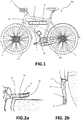
- reference 100 generally indicates a bicycle.
- the bicycle 100 comprises a first 101 and second wheels 102, for example corresponding to the front wheel and rear wheel.
- a brake is associated to at least the first wheel 101, the brake being actuatable by a knob located on the handlebar, for example.
- the braking system can be of any known type, for example a pad or disk brake, commanded by a mechanical system, for example a cable or hydraulic system.
- the bicycle 100 comprises a brake assist system 1 for a cyclist of the bicycle itself.
- the system 1 does not actively control the braking, on the contrary it communicates, by a vibrating haptic feedback, to the cyclist the emergence of possibly dangerous events, particularly the slippage or a possible slippage of the first wheel 101, or the initial flipping-over of the bicycle around the same due to a braking.
- the slippage events are typical of bicycles having narrow wheels and tires, for example racing bicycles, while the flipping-over is typical of bicycles having large wheels and tires, for example mountain bikes.
- the basic principle of the system is the same and consists of correcting the slippage for preventing the flipping-over, according to the type of a considered bicycle, in other words to provide a vibrating haptic feedback advising the cyclist about a dangerous condition.
- the system 1 comprises an actuator 4 adapted to generate vibrations.
- the actuator 4 can comprise an eccentric mass such to generate vibrations when is rotated.
- the actuator 4 can be mounted to a portion of the bicycle so that, when the actuator vibrates, the vibrations can be perceived by the cyclist.
- the actuator 4 is mounted to the brake lever of the first wheel 101, which is the wheel subjected to a slippage or around which a flipping-over caused by an excessively intense brake can occur. Therefore, the vibrating feedback is transferred to the lever on which the cyclist must act for modulating the braking.
- the actuator 4 can for example be received inside a groove 32 typically present in the rear portion of the brake lever 33.
- the actuator 4 can be placed in the groove 32 for example by a housing, not shown in the figures, configured to close the groove 32 for protecting the actuator 4 from the weather, besides preventing the cyclist hand from contacting the actuator 4 itself.
- the actuator 4 is made integral to the brake lever 33 by the housing.
- the actuator is supplied and controlled by electric wires 37.
- the actuator 4 is of a DC brushed type and can be voltage- or current-controlled.
- a battery 23 is preferably associated to the actuator 4 for supplying and moving the latter.
- the system 1 comprises a first sensor 2 for measuring the angular speed ⁇ 1 of the first wheel 101, particularly of the front wheel.
- the first sensor 2 is adapted to generate a signal representative of such angular speed of the first wheel.
- Such first sensor 2 can transmit the signal representative of the angular speed ⁇ 1 of the first wheel 101 either wirelessly or by wire.
- the system 1 can further comprise a second sensor 3 for measuring the angular speed ⁇ 2 of the second wheel 102, particularly of the rear wheel.
- the bicycle speed v can be used by the system 1, according to the invention, as it will be explained in the following.
- the bicycle speed if is necessary, can be alternatively derived from other sensors, for example inertial sensors, so that the second sensor 3 for measuring the angular speed ⁇ 2 of the second wheel 102 can be omitted.
- the system further comprises a module for determining the slope angle ⁇ of the bicycle, in other words the road slope, and adapted to supply a signal representing the same. This can be calculated in different ways.
- the module for determining the slope ⁇ comprises a dedicated slope sensor adapted to supply a signal representing the same.
- the slope ⁇ can be obtained from signals representing inertial magnitudes of the bicycle, for example according to what is described in: M. Corno, P. Spagnol, S. M. Savaresi S "Road Slope Estimation in Bicycles without Torque Measurements".
- the system 1 can comprise an inertial measuring unit 18 adapted to measure one or more among the longitudinal a x , lateral a y and vertical accelerations a z , and/or one or more among the roll ⁇ x , yaw ⁇ y , and pitch angular speeds ⁇ z of the bicycle, and adapted to generate signals representing the same.
- the inertial measuring unit 18 can be advantageously further used for further operations of the system 1 according to the invention.
- the speed v of the bicycle can be calculated by integrating over time limited intervals the longitudinal acceleration a x supplied by the inertial measuring unit 18.
- the system 1 comprises a sensor for detecting the braking action of a user, adapted to supply a signal representing the same.
- a sensor for detecting the braking action of a user, adapted to supply a signal representing the same.
- such sensor can comprise a switch (not shown in the figures) coupled with the brake lever 33, capable of detecting when this is actuated by the cyclist.
- the braking can be detected also without such sensor, particularly by the signal from the speed sensor 2 of the first wheel 101.
- the system 1 comprises a module for detecting a pedal-thrust input of the cyclist (not shown in the figures).
- a pedal-thrust input of the cyclist can comprise a pedal-thrust torque sensor mounted to the bicycle pedals, or a pedal-thrust speed sensor, mounted to the pedals or a free-wheel mechanism preferably placed at the rear wheel, wherein the chain unloads the driving torque applied by the cyclist to the wheel.
- the pedal-thrust input can be obtained from signals supplied by the angular speed sensor 2 of the first wheel 101 and/or by the inertial measuring unit 18 according to known estimate algorithms.
- the pedal-thrust rate is possibly obtained from what is disclosed in the patent application WO 2017/089904 filed by the Applicant, the contents thereof being herein incorporated by reference.
- the system 1 comprises a control module 5 adapted to generate a command signal to the actuator 4 so that this latter vibrates at a determined vibration frequency f.
- the command signal to the actuator can be determined based on signals from one or more of the system 1 sensors and based on one or more reference magnitudes.
- the system further comprises a learning module 50 configured to determine and supply to the control module 5 said one or more reference magnitudes.
- the one or more reference magnitudes, as determined by the learning module 50 represent the skillfulness of a cyclist, and are determined based on signals from one or more of the system 1 sensors, according to what will be described in the following.
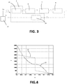
- Figure 3 shows the block 6 representing the cyclist, which acts with a determined force F c on the brake lever for actuating the first wheel brake. Consequently, the bicycle braking system, represented by block 7, transforms such force F c into a braking torque T on the first wheel.
- the block 8 represents the bicycle and takes into consideration the dynamics established by the tire and road, which can determine a slippage of the first wheel with respect to the road. This is due to several factors, among them the road conditions, tire conditions, road slope, bicycle roll angle.
- the control module 5 comprises a module 24 for estimating the (linear) deceleration ⁇ of the first wheel.
- the control module 5 determines the vibration frequency f that the actuator 4 must have, based on a static map stored in a memory module 25 of the control module itself.
- Figure 4 shows two possible curves establishing a relationship between the vibration frequency and the deceleration error e ⁇ .
- a discontinuity is provided when the deceleration error e ⁇ is zero.
- the derivative is equal to zero. Consequently, the frequency f stays about constant and is subjected to minimal variations about such condition.
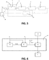
- the vibration frequency f of the actuator is also affected by the effective speed v of the bicycle.
- the frequency determined based on the static map of the memory module 25 is amplified by a factor kv, wherein k is a constant and v is the bicycle speed.
- k is a constant
- v is the bicycle speed.
- This latter can be determined from the signal representing the longitudinal acceleration a x , supplied by the inertial measuring unit 18, or from the signal representing the angular speed ⁇ 2 of the second wheel, if present. Therefore, the frequency f depends on the bicycle speed v, particularly is amplified as the bicycle speed v increases.
- the learning module 50 can be configured to supply to the control module the reference deceleration ⁇ ref .
- the learning module 50 determines and updates a cyclist profile as he/she uses the bicycle, and determines the reference deceleration ⁇ ref , by also progressively updating it.
- Figure 6 shows a schematic representation of the learning module 50 according to a possible embodiment of the invention.
- the learning module 50 comprises a braking detecting module 51 configured to detect when a cyclist is braking.
- the module 51 can determine the occurrence of a braking if it receives, at the input, the signal from the previously cited braking sensor, if is present.
- the braking sensor If the braking sensor is omitted, it is possible to determine the occurrence of a braking, by the signal representing the angular speed ⁇ 1 of the first wheel.
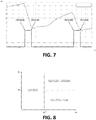
- Figure 7 shows a possible trend during time t of such speed, wherein two abrupt reductions of the same are shown, having a start ("start braking") and a stop (“stop braking”) corresponding to the breakings.
- the module 51 finds the brakings because it performs an analysis of the angular speed ⁇ 1 of the first wheel during time t.
- the brakings are analytically detectable for example by analyzing the angular acceleration (obtainable by time deriving the angular speed ⁇ 1 of the first wheel) and the jerk (obtainable by time deriving the angular acceleration of the first wheel) of the first wheel.
- the angular acceleration of the first wheel will jump, while the angular jerk of the first wheel will show a peak during braking.
- the module 51 generates a signal indicative of the presence of a braking ("brake").
- the learning module 50 comprises a braking classifying module 52 configured to classify each braking event based on at least the signal representing the first wheel speed ⁇ 1 , preferably further based on the signal representing the slope ⁇ and to output, at each braking event detected by the braking detection module 51, one or more parameters representing such classification.
- a braking classifying module 52 configured to classify each braking event based on at least the signal representing the first wheel speed ⁇ 1 , preferably further based on the signal representing the slope ⁇ and to output, at each braking event detected by the braking detection module 51, one or more parameters representing such classification.
- FIG 8 it shows a diagram of a possible braking classification.
- the abscissa represents the speed ⁇ 1 of the first wheel, and the ordinate the slope ⁇ .
- the diagram shows three quadrants:
- a threshold speed ⁇ 1 * separating the low speed from the high speed.
- the braking is determined as a downhill or plain braking based on a threshold slope, preferably equal to 0° (eventually ⁇ a constant).
- a threshold slope preferably equal to 0° (eventually ⁇ a constant).
- the parameters representing the braking can include, for example, a more or less high score, based on the tendency of the cyclist to brake at high or low speeds, along downhill or on plain.
- the classification can be only performed based on the angular speed of the first wheel.
- the braking classifying module 52 is configured to further classify the braking based on the roll angle of the bicycle and/or based on the pedal-thrust input detected before braking.
- the bicycle roll angle can be obtained from the signal representing the roll angular speed ⁇ x supplied by the inertial measuring unit 18, while the pedal-thrust input can be detected by the beforehand cited module for detecting the pedal-thrust input (the torque or speed/pedal-thrust rate).
- the learning module 50 further comprises a module for optimizing the reference magnitudes 53, configured to receive at the input the parameters representing the braking classification, supplied by the module 52, and to generate a cyclist profile by a progressive update. Moreover, the module for optimizing the reference magnitudes 53, based on the progressively updated profile, determines the reference magnitudes supplied to the control module 5. With reference to the embodiments shown in Figures 3 and 5 , the module for optimizing the reference magnitudes 53 can for example determine and update, during the cyclist run, the reference deceleration ⁇ ref . Therefore, if the cyclist is classified as prudent, the reference deceleration ⁇ ref could assume a low value (in absolute value) while, if the cyclist is more aggressive, the reference deceleration could assume a higher value (in absolute value).
- the module for optimizing the reference magnitudes 53 can further receive, at the input, in order to determine the reference magnitudes, one or more of the following information:
- the system 1 can for example comprise a GPS module for geopositioning the bicycle during the motion thereof.
- said information can be locally saved in a memory module of the system 1.
- the information can be stored in a remote system 54, for example in a cloud system.
- the system 1 can comprise a transmission module for supplying and receiving data to/from the remote system.
- the system 1 can be connected to a mobile device of the cyclist, for example a smartphone, storing a dedicated application.
- a hybrid system can be further provided in which some information are locally saved, and other information are remotely saved.
- control module 5 can be configured according to each of the embodiment variants described in the international patent application WO 2016/203331 , the content thereof being integrally incorporated by reference.
- the reference magnitudes which can be updated by the learning module 50 can include:
- the actuator 4 can be voltage- or current-controlled.
- the system 1 comprises a voltage-control module of the actuator (not shown in the figures) receiving, at the input, the command signal, and consequently supplying the actuator 4 with a voltage adapted to vibrate the actuator at the determined vibration frequency.
- the system 1 comprises a current-control module 34 of the actuator, schematically illustrated in Figure 9 .
- the module 34 receives, at the input, the desired vibration frequency determined by the previously described modes, indicated in this case as a reference frequency f ref .
- the module 34 comprises a memory module 35 storing a static map relating the reference vibration frequency f ref to a reference current l ref .
- An example of such map is shown in Figure 10 . Therefore, a reference current l ref corresponding to the reference vibration frequency f ref is obtained at the output of the memory module 35.
- the module 34 performs a closed-loop control of the actuator current 4.
- the module 34 comprises a current sensor measuring the motor effective current l, from which a current error ei between the reference current l ref and effective current l is determined.
- the module 34 comprises a voltage command module 36 determining the DC (duty cycle) voltage to be applied across the actuator 4 so that the current error ei is minimized, in other words so that the effective current l substantially follows the trend of the reference current l ref . Due to the current l set in this way, the actuator 4 will vibrate at an effective frequency f which follows the trend of the reference frequency f ref .
- Such current-control method enables to have faster response times than the ones of the voltage-control, and further enables to prevent too high currents from flowing in the actuator 4.
- system 1 and also the elements indicated by the term “module”, can be implemented by hardware devices (control units, for example), by software or by a hardware and software combination.
Landscapes
- Engineering & Computer Science (AREA)
- Mechanical Engineering (AREA)
- Transportation (AREA)
- Regulating Braking Force (AREA)
- Motorcycle And Bicycle Frame (AREA)
Description
- The present invention refers to a brake assist system for a cyclist on a bicycle by an haptic feedback, particularly a system adapted to aid the cyclist to prevent a braking wheel from excessively slipping (consequently from loosing the lateral stability), or from possibly flipping over the bicycle, due to too high decelerations. The system according to the invention is configured to adapt to the ability of a cyclist.
- Braking a bicycle, especially the front wheel thereof, is an action requiring a cyclist to have a determined sensibility and if he/she does not correctly brake, risks and problems can rise. For example, with reference to racing bicycles provided with narrow wheels and tires, an improperly modulated braking, particularly a too intense braking, can cause dangerous slippages which can cause falls. On the contrary, bicycles provided with large wheels and tires, such as mountain bikes, slipping is less risky, however on the other side the same large tire, in case of a too intense braking of the front wheel, can cause the bicycle itself to flip over around this wheel.
- The Applicant, in order to overcome this problem, filed the international patent application
WO 2016/203331 , regarding a brake assist system for a cyclist on a bicycle by an haptic feedback, wherein an actuator is vibrated at a determined frequency if slippage conditions and/or a risk of flipping over the front wheel are determined. The operation of such system is based on the comparison between the effective motion conditions detected by bicycle sensors and preset reference conditions, manually selectable by the cyclist among a plurality of predefined options. The vibration of the actuator is managed as a function of such comparison. The documentWO 2016/203331 discloses an adaptive brake assist system in accordance with the preamble ofclaim 1. - However, such system has the inconvenience of not being sufficiently adaptable because is based on preset reference conditions which do not necessarily correspond to the real driving skillfulness of a cyclist.
- Therefore, an object of the present invention is that of providing a brake assist system for a cyclist on a bicycle by an haptic feedback capable of adapting to the driving skillfulness of each specific cyclist.
- This and other objects are obtained by an adaptive brake assist system for a cyclist on a bicycle by an haptic feedback according to
claim 1. - The dependent claims define possible advantageous embodiments of the invention.
- In order to gain a better comprehension of the invention and appreciate the advantages thereof, some illustrative non-limiting embodiments thereof will be described in the following with reference to the attached figures, wherein:
-
Figure 1 is a schematic illustration of a bicycle provided with a brake assist system according to a possible embodiment of the invention; -
Figures 2a and 2b are two schematic illustrations of possible positions of an actuator of the system in a brake lever of the bicycle, a mountain bike and a racing bicycle respectively; -
Figure 3 is a block diagram of a brake assist system according to a possible embodiment of the invention; -
Figure 4 is a diagram showing two possible curves of a vibration frequency versus a deceleration error of the first wheel of the bicycle; -
Figure 5 is a block diagram of a brake assist system according to a further possible embodiment of the invention; -
Figure 6 is a block diagram of a learning module of the brake assist system according to a possible embodiment; -
Figure 7 is a diagram illustrating a possible trend of the speed of a bicycle wheel versus the time for determining a braking action on it; -
Figure 8 is a diagram illustrating a possible classification of the brakings based on the angular speed of a bicycle wheel and slope; -
Figure 9 is a block diagram of a current control module of the actuator of the system according to a possible embodiment of the invention; -
Figure 10 is a diagram illustrating a possible relationship between a reference frequency and a reference current for a current-control of the actuator of the system according to a possible embodiment of the invention. - With reference to
Figure 1 ,reference 100 generally indicates a bicycle. Thebicycle 100 comprises a first 101 andsecond wheels 102, for example corresponding to the front wheel and rear wheel. A brake is associated to at least thefirst wheel 101, the brake being actuatable by a knob located on the handlebar, for example. The braking system can be of any known type, for example a pad or disk brake, commanded by a mechanical system, for example a cable or hydraulic system. - The
bicycle 100 comprises abrake assist system 1 for a cyclist of the bicycle itself. As it will be explained, thesystem 1 does not actively control the braking, on the contrary it communicates, by a vibrating haptic feedback, to the cyclist the emergence of possibly dangerous events, particularly the slippage or a possible slippage of thefirst wheel 101, or the initial flipping-over of the bicycle around the same due to a braking. The slippage events are typical of bicycles having narrow wheels and tires, for example racing bicycles, while the flipping-over is typical of bicycles having large wheels and tires, for example mountain bikes. However, the basic principle of the system is the same and consists of correcting the slippage for preventing the flipping-over, according to the type of a considered bicycle, in other words to provide a vibrating haptic feedback advising the cyclist about a dangerous condition. - For this purpose, the
system 1 comprises anactuator 4 adapted to generate vibrations. For example, theactuator 4 can comprise an eccentric mass such to generate vibrations when is rotated. Theactuator 4 can be mounted to a portion of the bicycle so that, when the actuator vibrates, the vibrations can be perceived by the cyclist. Preferably, theactuator 4 is mounted to the brake lever of thefirst wheel 101, which is the wheel subjected to a slippage or around which a flipping-over caused by an excessively intense brake can occur. Therefore, the vibrating feedback is transferred to the lever on which the cyclist must act for modulating the braking. - With references to
Figures 2a and 2b , respectively illustrating a detail of the handlebar of a mountain bike or of a racing bicycle, theactuator 4 can for example be received inside agroove 32 typically present in the rear portion of thebrake lever 33. Theactuator 4 can be placed in thegroove 32 for example by a housing, not shown in the figures, configured to close thegroove 32 for protecting theactuator 4 from the weather, besides preventing the cyclist hand from contacting theactuator 4 itself. Theactuator 4 is made integral to thebrake lever 33 by the housing. The actuator is supplied and controlled byelectric wires 37. - Preferably, the
actuator 4 is of a DC brushed type and can be voltage- or current-controlled. - A
battery 23 is preferably associated to theactuator 4 for supplying and moving the latter. - The
system 1 comprises afirst sensor 2 for measuring the angular speed ω1 of thefirst wheel 101, particularly of the front wheel. Thefirst sensor 2 is adapted to generate a signal representative of such angular speed of the first wheel. Suchfirst sensor 2 can transmit the signal representative of the angular speed ω1 of thefirst wheel 101 either wirelessly or by wire. - According to a possible embodiment, the
system 1 can further comprise asecond sensor 3 for measuring the angular speed ω2 of thesecond wheel 102, particularly of the rear wheel. Thesecond sensor 3 is adapted to generate a signal representing such angular speed of the second wheel. From the signal representing the angular speed ω2 of thesecond wheel 102, it is possible to determine the speed v of the bicycle, assuming the second wheel is not slipping, from the relationship v = ω2R2, wherein R2 is the radius of thesecond wheel 102. Optionally, the bicycle speed v can be used by thesystem 1, according to the invention, as it will be explained in the following. Moreover, the bicycle speed, if is necessary, can be alternatively derived from other sensors, for example inertial sensors, so that thesecond sensor 3 for measuring the angular speed ω2 of thesecond wheel 102 can be omitted. - According to a possible embodiment, the system further comprises a module for determining the slope angle θ of the bicycle, in other words the road slope, and adapted to supply a signal representing the same. This can be calculated in different ways.
- According to a possible embodiment, the module for determining the slope θ comprises a dedicated slope sensor adapted to supply a signal representing the same. Alternatively, the slope θ can be obtained from signals representing inertial magnitudes of the bicycle, for example according to what is described in: M. Corno, P. Spagnol, S. M. Savaresi S "Road Slope Estimation in Bicycles without Torque Measurements". For this purpose, the
system 1 can comprise aninertial measuring unit 18 adapted to measure one or more among the longitudinal ax, lateral ay and vertical accelerations az, and/or one or more among the roll ωx, yaw ωy, and pitch angular speeds ωz of the bicycle, and adapted to generate signals representing the same. As it will be explained, theinertial measuring unit 18 can be advantageously further used for further operations of thesystem 1 according to the invention. Particularly, for example, the speed v of the bicycle can be calculated by integrating over time limited intervals the longitudinal acceleration ax supplied by theinertial measuring unit 18. - According to an embodiment, the
system 1 comprises a sensor for detecting the braking action of a user, adapted to supply a signal representing the same. For example, such sensor can comprise a switch (not shown in the figures) coupled with thebrake lever 33, capable of detecting when this is actuated by the cyclist. Alternatively, as it will be described, the braking can be detected also without such sensor, particularly by the signal from thespeed sensor 2 of thefirst wheel 101. - According to the invention, the
system 1 comprises a module for detecting a pedal-thrust input of the cyclist (not shown in the figures). For example, such module can comprise a pedal-thrust torque sensor mounted to the bicycle pedals, or a pedal-thrust speed sensor, mounted to the pedals or a free-wheel mechanism preferably placed at the rear wheel, wherein the chain unloads the driving torque applied by the cyclist to the wheel. Alternatively, the pedal-thrust input can be obtained from signals supplied by theangular speed sensor 2 of thefirst wheel 101 and/or by the inertial measuringunit 18 according to known estimate algorithms. For example, the pedal-thrust rate is possibly obtained from what is disclosed in the patent applicationWO 2017/089904 filed by the Applicant, the contents thereof being herein incorporated by reference. - The
system 1 comprises acontrol module 5 adapted to generate a command signal to theactuator 4 so that this latter vibrates at a determined vibration frequency f. The command signal to the actuator can be determined based on signals from one or more of thesystem 1 sensors and based on one or more reference magnitudes. - According to the invention, the system further comprises a
learning module 50 configured to determine and supply to thecontrol module 5 said one or more reference magnitudes. The one or more reference magnitudes, as determined by thelearning module 50, represent the skillfulness of a cyclist, and are determined based on signals from one or more of thesystem 1 sensors, according to what will be described in the following. - Referring to the attached figures, possible embodiments of the invention will be now described.
- For example,
Figure 3 shows theblock 6 representing the cyclist, which acts with a determined force Fc on the brake lever for actuating the first wheel brake. Consequently, the bicycle braking system, represented byblock 7, transforms such force Fc into a braking torque T on the first wheel. Theblock 8 represents the bicycle and takes into consideration the dynamics established by the tire and road, which can determine a slippage of the first wheel with respect to the road. This is due to several factors, among them the road conditions, tire conditions, road slope, bicycle roll angle. - The
control module 5 comprises amodule 24 for estimating the (linear) deceleration η of the first wheel. Specifically, the estimatingmodule 24 is configured to determine the deceleration of the first wheel from the angular speed ω1 of the first wheel, by deriving it the angular deceleration and therefore the first wheel and consequently the linear deceleration of the first wheel ω 1 can be obtained based on the formula:
first wheel 101. - The
control module 5 determines the vibration frequency f that theactuator 4 must have, based on a static map stored in amemory module 25 of the control module itself.Such memory module 25 can particularly receive, at the input, the error eη between a reference deceleration ηref and deceleration η of the first wheel determined as said before:
-
Figure 4 shows two possible curves establishing a relationship between the vibration frequency and the deceleration error eη. - According to a
first curve 26, a discontinuity is provided when the deceleration error eη is zero. According to asecond curve 27, at a zero deceleration error eη, the derivative is equal to zero. Consequently, the frequency f stays about constant and is subjected to minimal variations about such condition. - According to a further possible variant illustrated in
Figure 5 , the vibration frequency f of the actuator is also affected by the effective speed v of the bicycle. Particularly, the frequency determined based on the static map of thememory module 25 is amplified by a factor kv, wherein k is a constant and v is the bicycle speed. This latter can be determined from the signal representing the longitudinal acceleration ax, supplied by the inertial measuringunit 18, or from the signal representing the angular speed ω2 of the second wheel, if present. Therefore, the frequency f depends on the bicycle speed v, particularly is amplified as the bicycle speed v increases. - Referring to the hereinbefore described embodiments of the
control module 5, thelearning module 50 can be configured to supply to the control module the reference deceleration ηref. Particularly, thelearning module 50 determines and updates a cyclist profile as he/she uses the bicycle, and determines the reference deceleration ηref, by also progressively updating it. -
Figure 6 shows a schematic representation of thelearning module 50 according to a possible embodiment of the invention. - According to such embodiment, the
learning module 50 comprises abraking detecting module 51 configured to detect when a cyclist is braking. - The
module 51 can determine the occurrence of a braking if it receives, at the input, the signal from the previously cited braking sensor, if is present. - If the braking sensor is omitted, it is possible to determine the occurrence of a braking, by the signal representing the angular speed ω1 of the first wheel. For example,
Figure 7 shows a possible trend during time t of such speed, wherein two abrupt reductions of the same are shown, having a start ("start braking") and a stop ("stop braking") corresponding to the breakings. Themodule 51 finds the brakings because it performs an analysis of the angular speed ω1 of the first wheel during time t. Particularly, the brakings are analytically detectable for example by analyzing the angular acceleration (obtainable by time deriving the angular speed ω1 of the first wheel) and the jerk (obtainable by time deriving the angular acceleration of the first wheel) of the first wheel. The angular acceleration of the first wheel will jump, while the angular jerk of the first wheel will show a peak during braking. - Referring again to
Figure 6 , during braking, themodule 51 generates a signal indicative of the presence of a braking ("brake"). - According to the invention, the
learning module 50 comprises abraking classifying module 52 configured to classify each braking event based on at least the signal representing the first wheel speed ω1, preferably further based on the signal representing the slope θ and to output, at each braking event detected by thebraking detection module 51, one or more parameters representing such classification. Referring toFigure 8 , it shows a diagram of a possible braking classification. The abscissa represents the speed ω1 of the first wheel, and the ordinate the slope θ. The diagram shows three quadrants: - LOW SPEED
- HIGH SPEED ― DOWNHILL
- HIGH SPEED ― PLAIN
- According to this example, it is provided a threshold speed ω1* separating the low speed from the high speed. Above the threshold speed ω1*, the braking is determined as a downhill or plain braking based on a threshold slope, preferably equal to 0° (eventually ± a constant). Generally, for example, a cyclist often braking at low speeds has a prudent behaviour, while a cyclist frequently braking at high speeds ― perhaps mainly along downhills ― and less at low speeds, has a more aggressive behaviour. The parameters representing the braking can include, for example, a more or less high score, based on the tendency of the cyclist to brake at high or low speeds, along downhill or on plain.
- Of course, it is possible to classify the braking by modes different from the above described ones. For example, without the signal representing the slope, the classification can be only performed based on the angular speed of the first wheel.
- According to the invention, the
braking classifying module 52 is configured to further classify the braking based on the roll angle of the bicycle and/or based on the pedal-thrust input detected before braking. The bicycle roll angle can be obtained from the signal representing the roll angular speed ωx supplied by the inertial measuringunit 18, while the pedal-thrust input can be detected by the beforehand cited module for detecting the pedal-thrust input (the torque or speed/pedal-thrust rate). - Referring again to
Figure 6 , advantageously, thelearning module 50 further comprises a module for optimizing thereference magnitudes 53, configured to receive at the input the parameters representing the braking classification, supplied by themodule 52, and to generate a cyclist profile by a progressive update. Moreover, the module for optimizing thereference magnitudes 53, based on the progressively updated profile, determines the reference magnitudes supplied to thecontrol module 5. With reference to the embodiments shown inFigures 3 and5 , the module for optimizing thereference magnitudes 53 can for example determine and update, during the cyclist run, the reference deceleration ηref. Therefore, if the cyclist is classified as prudent, the reference deceleration ηref could assume a low value (in absolute value) while, if the cyclist is more aggressive, the reference deceleration could assume a higher value (in absolute value). - According to a possible embodiment, the module for optimizing the
reference magnitudes 53 can further receive, at the input, in order to determine the reference magnitudes, one or more of the following information: - sex of the cyclist;
- age of the cyclist;
- type of the bicycle;
- type of brakes;
- positioning.
- For example, it is possible to foresee a lower reference deceleration ηref for older cyclist. In addition, it is possible to obtain information from the positioning, such as for example: weather conditions, road surface conditions, etcetera. With reference to the positioning, the
system 1 can for example comprise a GPS module for geopositioning the bicycle during the motion thereof. - It is observed that said information can be locally saved in a memory module of the
system 1. Alternatively, the information can be stored in aremote system 54, for example in a cloud system. For this purpose, thesystem 1 can comprise a transmission module for supplying and receiving data to/from the remote system. According to a variant, thesystem 1 can be connected to a mobile device of the cyclist, for example a smartphone, storing a dedicated application. A hybrid system can be further provided in which some information are locally saved, and other information are remotely saved. - Even though the present description refers to the reference deceleration ηref as a reference magnitude which is updated by the
learning module 50, it is observed that this latter can act also on reference magnitudes of different type. - Particularly, the
control module 5 can be configured according to each of the embodiment variants described in the international patent applicationWO 2016/203331 , the content thereof being integrally incorporated by reference. - So that, in a non-limiting illustrative way, referring also to the contents of the international patent application
WO 2016/203331 , the reference magnitudes which can be updated by thelearning module 50, can include: - static maps correlating input magnitudes (the effective slippage λ of the first wheel, slippage error eλ, parameter R representing the flipping-over risk, error eη between the reference deceleration ηref and effective deceleration η of the first wheel, effective deceleration η of the first wheel, error eε between a mixed magnitude of reference deceleration and slippage εref and a mixed magnitude of effective deceleration and slippage ε of the first wheel, etcetera) to the vibration frequency f of the actuator;
- amplification constant k of the vibration frequency of the actuator, as defined by the static maps, as a function of the bicycle speed v;
- reference slippage λref, reference slippage λφ ref, varying as a function of the roll angle φ, a mixed magnitude of the reference deceleration and slippage εref.
- Once determined the vibration frequency f by the above described modes, it is necessary to control the
actuator 4 itself so that this effectively vibrates at such vibration frequency. - Alternatively, the
actuator 4 can be voltage- or current-controlled. - If the
actuator 4 is voltage-controlled, it suffices to modify the supply voltage of the actuator, based on the determined vibration frequency. Therefore, according to such variant, thesystem 1 comprises a voltage-control module of the actuator (not shown in the figures) receiving, at the input, the command signal, and consequently supplying theactuator 4 with a voltage adapted to vibrate the actuator at the determined vibration frequency. - According to a further variant, if the
actuator 4 is current-controlled, thesystem 1 comprises a current-control module 34 of the actuator, schematically illustrated inFigure 9 . - According to this variant, the
module 34 receives, at the input, the desired vibration frequency determined by the previously described modes, indicated in this case as a reference frequency fref. - The
module 34 comprises amemory module 35 storing a static map relating the reference vibration frequency fref to a reference current lref. An example of such map is shown inFigure 10 . Therefore, a reference current lref corresponding to the reference vibration frequency fref is obtained at the output of thememory module 35. - Consequently, the
module 34 performs a closed-loop control of the actuator current 4. For this purpose, themodule 34 comprises a current sensor measuring the motor effective current l, from which a current error ei between the reference current lref and effective current l is determined. - Moreover, the
module 34 comprises avoltage command module 36 determining the DC (duty cycle) voltage to be applied across theactuator 4 so that the current error ei is minimized, in other words so that the effective current l substantially follows the trend of the reference current lref. Due to the current l set in this way, theactuator 4 will vibrate at an effective frequency f which follows the trend of the reference frequency fref. - Generally, such current-control method enables to have faster response times than the ones of the voltage-control, and further enables to prevent too high currents from flowing in the
actuator 4. - It is observed that in the present description and in the attached claims, the
system 1 and also the elements indicated by the term "module", can be implemented by hardware devices (control units, for example), by software or by a hardware and software combination.
Claims (14)
- Adaptive brake assist system (1) for a cyclist on a bicycle (100) by an haptic feedback, comprising:- a first sensor (2) for measuring the angular speed (ω1) of a first wheel (101) of the bicycle, adapted to generate a signal representative of the angular speed of the first wheel (101);- an actuator (4) mountable to a portion of the bicycle, adapted to generate vibrations;- a control module (5) configured for generating a command signal of the actuator (4), so that the actuator vibrates with a vibration frequency (f), based on at least said signal representative of the angular speed of the first wheel (ω1) and based on one or more reference magnitudes (ηref);characterized in that it further comprises:- a learning module (50) configured for determining, updating and delivering to the control module (5) said one or more reference magnitudes (ηref) based on at least the signal representative of the angular speed (ω1) of the first wheel (101), wherein the learning module (50) comprises:a module for sensing the braking (51) configured for sensing when the cyclist is braking and for outputting a signal representative of the braking presence, anda braking classifying module (52), configured for classifying each braking event as sensed by the braking sensing module (51) based on at least the signal representative of the angular speed of the first wheel (ω1), and for delivering one or more parameters representative of such classification of the braking.
- System (1) according to claim 1, further comprising a module for determining the slope angle (θ) of the bicycle, adapted to deliver a signal representative of the same, wherein the learning module (50) is configured for determining, updating and delivering to the control module (5) said one or more reference magnitudes (ηref) further based on the slope (θ) of the bicycle.
- System (1) according to claim 1 or 2, comprising an inertial measuring unit (18) adapted to measure the longitudinal (ax) and/or lateral (ay) and/or vertical accelerations (az), and/or the roll (ωx) and/or pitch (ωy) and/or jaw (ωz) angular speeds of the bicycle, and to generate signals representative of the same.
- System (1) according to claim 2 or 3, wherein said module for determining the slope (θ) comprises a slope sensor adapted to deliver a signal representative of the same.
- System (1) according to claims 2 and 3, wherein said module for determining the slope (θ) is configured for determining said signal representative of the slope (θ) from the signals of the inertial measuring unit (18).
- System (1) according to any of claims from 1 to 5, wherein said braking sensing module (51) comprises a sensor for sensing the braking action by a user, adapted to deliver a signal representative of the same.
- System (1) according to any of claims from 1 to 5, wherein said braking sensing module (51) is configured for sensing when the cyclist is braking based on said signal representative of the angular speed of the first wheel (ω1).
- System (1) according to claim 2 or according to any of the preceding claims when dependent on claim 2, wherein said braking classifying module (52) is configured for classifying each braking event as sensed by the braking sensing module (51) and for delivering said one or more parameters representative of such classification of the braking further based on the signal representative of the slope (θ).
- System (1) according to claim 3 or according to any of the preceding claims when dependent on claim 3, wherein said braking classifying module (52) is configured for classifying each braking event as sensed by the braking sensing module (51) and for delivering said one or more parameters representative of such classification of the braking further based on the roll angle of the bicycle as determined from the signal representative of the roll angular speed (ωx) sensed before braking.
- System (1) according to any of the preceding claims, comprising a module for detecting a pedal-thrust input from a cyclist, adapted to deliver a signal representative of the same, wherein said braking classifying module (52) is configured for classifying each braking event as sensed by the braking sensing module (51) and for delivering said one or more parameters representative of such classification of the braking further based on the signal representative of the pedal-thrust input from the cyclist, sensed before braking.
- System (1) according to any of the preceding claims, wherein the learning module (50) further comprises a module for optimizing the reference magnitudes (53), configured for:- generating a cyclist profile, by progressively updating it, based on one or more parameters representative of the classification of the braking;- determining said one or more reference magnitudes (ηref) based on the cyclist profile.
- System (1) according to claim 11, wherein said reference magnitudes optimizing module (53) is configured for generating the cyclist profile further based on the sex of the cyclist and/or age of the cyclist and/or the type of bicycle and/or the type of brakes and/or based on the location.
- System (1) according to any of the preceding claims, wherein said first wheel (101) is a front wheel of the bicycle (100).
- Bicycle (100) comprising a first (101) and second wheels (102), a brake lever (33) for braking one of said first (101) and second wheels (102), and an adaptive brake assist system according to any of the preceding claims.
Applications Claiming Priority (2)
| Application Number | Priority Date | Filing Date | Title |
|---|---|---|---|
| IT201700135958 | 2017-11-27 | ||
| PCT/IB2018/058767 WO2019102290A1 (en) | 2017-11-27 | 2018-11-08 | Adaptive brake assist system for a cyclist on a bicycle by an aptic feedback |
Publications (2)
| Publication Number | Publication Date |
|---|---|
| EP3717318A1 EP3717318A1 (en) | 2020-10-07 |
| EP3717318B1 true EP3717318B1 (en) | 2021-12-22 |
Family
ID=61581519
Family Applications (1)
| Application Number | Title | Priority Date | Filing Date |
|---|---|---|---|
| EP18803789.9A Active EP3717318B1 (en) | 2017-11-27 | 2018-11-08 | Adaptive brake assist system for a cyclist on a bicycle by an aptic feedback |
Country Status (5)
| Country | Link |
|---|---|
| US (1) | US11260836B2 (en) |
| EP (1) | EP3717318B1 (en) |
| JP (1) | JP7219277B2 (en) |
| CN (1) | CN111741878B (en) |
| WO (1) | WO2019102290A1 (en) |
Families Citing this family (8)
| Publication number | Priority date | Publication date | Assignee | Title |
|---|---|---|---|---|
| JP7156908B2 (en) * | 2018-10-31 | 2022-10-19 | 株式会社シマノ | Controller and detector |
| IT201900004069A1 (en) * | 2019-03-20 | 2020-09-20 | Blubrake S R L | System for improving the performance of a cyclist on a bicycle |
| CN111307172B (en) * | 2020-03-03 | 2022-11-08 | 北京骑胜科技有限公司 | Bicycle and method for determining bicycle riding information |
| US12151770B2 (en) | 2021-12-22 | 2024-11-26 | Zero Motorcycles, Inc. | Switchgear for vehicle and vehicle including switchgear |
| CN114872725B (en) * | 2022-05-30 | 2023-04-14 | 大拓无限(重庆)智能科技有限公司 | Intelligent control system for electric two-wheeled vehicles |
| EP4357152B1 (en) * | 2022-10-19 | 2025-08-20 | Hochschule Für Angewandte Wissenschaften München | Anti-lock braking system |
| DE102023202197A1 (en) | 2023-03-10 | 2024-09-12 | Robert Bosch Gesellschaft mit beschränkter Haftung | Method for outputting information on a deceleration process |
| CN119718087B (en) * | 2025-02-25 | 2025-06-20 | 厦门理工学院 | Interactive method for wearable multi-mode haptic feedback system of rider |
Family Cites Families (10)
| Publication number | Priority date | Publication date | Assignee | Title |
|---|---|---|---|---|
| JP2006193069A (en) | 2005-01-14 | 2006-07-27 | Toyota Motor Corp | Vehicle alarm device |
| US7944343B2 (en) * | 2007-10-07 | 2011-05-17 | Audi Ag | System and method for providing information in a vehicle |
| FR2923596B1 (en) * | 2007-11-09 | 2010-01-15 | Michelin Soc Tech | SYSTEM FOR MONITORING THE BEHAVIOR OF THE GROUND OF A VEHICLE COMPRISING A DETERMINATION OF THE SLOPE OF THE BEARING FLOOR 1 |
| JP2010061608A (en) | 2008-09-08 | 2010-03-18 | Denso Corp | Object detection apparatus |
| DE102013205245A1 (en) * | 2013-03-25 | 2014-09-25 | Continental Teves Ag & Co. Ohg | Vehicle reference speed determination method and vehicle control unit with such a method |
| GB201311001D0 (en) * | 2013-06-20 | 2013-08-07 | Lucabella Holdings Llc | Lucabella |
| EP3245093B1 (en) | 2015-01-12 | 2021-09-01 | Harman International Industries, Incorporated | Cognitive load driving assistant |
| US10293878B2 (en) | 2015-06-19 | 2019-05-21 | Blubrake S.R.L. | Brake assist system for a cyclist on a bicycle by a haptic feedback |
| CN105711701A (en) | 2015-12-31 | 2016-06-29 | 天津百世达科技有限公司 | Intelligent bicycle |
| ITUB20160057A1 (en) | 2016-02-04 | 2017-08-04 | E Novia S P A | Assistance system for riding a bicycle by sending a haptic feedback to the cyclist |
-
2018
- 2018-11-08 EP EP18803789.9A patent/EP3717318B1/en active Active
- 2018-11-08 WO PCT/IB2018/058767 patent/WO2019102290A1/en not_active Ceased
- 2018-11-08 US US16/766,785 patent/US11260836B2/en active Active
- 2018-11-08 CN CN201880082191.7A patent/CN111741878B/en not_active Expired - Fee Related
- 2018-11-08 JP JP2020528954A patent/JP7219277B2/en active Active
Also Published As
| Publication number | Publication date |
|---|---|
| JP2021504219A (en) | 2021-02-15 |
| CN111741878A (en) | 2020-10-02 |
| US11260836B2 (en) | 2022-03-01 |
| WO2019102290A1 (en) | 2019-05-31 |
| CN111741878B (en) | 2022-06-14 |
| US20200298809A1 (en) | 2020-09-24 |
| JP7219277B2 (en) | 2023-02-07 |
| EP3717318A1 (en) | 2020-10-07 |
Similar Documents
| Publication | Publication Date | Title |
|---|---|---|
| US11260836B2 (en) | Adaptive brake assist system for a cyclist on a bicycle by an haptic feedback | |
| JP6764476B2 (en) | Brake assist system for cyclists with tactile feedback | |
| EP3411285B1 (en) | System for assisting in driving a bicycle by sending a haptic feedback to a cyclist | |
| CN103448552A (en) | Display apparatus for vehicles | |
| EP2974900A1 (en) | Straddle-type vehicle | |
| US10040509B1 (en) | Control system for electric bicycles | |
| JP6067939B2 (en) | Pitch angle control system, pitch angle control method, and vehicle | |
| KR101243075B1 (en) | Controlling method and apparatus of adaptive cruise control system for vehicles | |
| CN110225850B (en) | Brake assist system for cyclists on bicycles | |
| JP2008522886A (en) | Apparatus and method for determining height of center of gravity of vehicle | |
| EP3253629A1 (en) | Control system | |
| KR102527810B1 (en) | Method and control device for operating an electric vehicle or a hybrid vehicle | |
| US11158142B2 (en) | Method for tire force reserve estimation | |
| KR101308355B1 (en) | An Electronic Stability Control System of Vehicle | |
| JP2006117102A (en) | Vehicle travel control device | |
| JP6248508B2 (en) | Vehicle driving support device | |
| KR20140133276A (en) | Control method of 4 wheel drive vehicle | |
| KR101339738B1 (en) | Tire-sensitized lane keeping support device and method of controlling the same | |
| JP2006056383A (en) | Body slip angle estimation method | |
| CN107635839A (en) | For the method and apparatus for the brake activated for detecting vehicle | |
| KR20170064269A (en) | Electronic stability control method in a vehicle and system thereof | |
| CN119502713A (en) | Traction control method and device for electric vehicle |
Legal Events
| Date | Code | Title | Description |
|---|---|---|---|
| STAA | Information on the status of an ep patent application or granted ep patent |
Free format text: STATUS: UNKNOWN |
|
| STAA | Information on the status of an ep patent application or granted ep patent |
Free format text: STATUS: THE INTERNATIONAL PUBLICATION HAS BEEN MADE |
|
| PUAI | Public reference made under article 153(3) epc to a published international application that has entered the european phase |
Free format text: ORIGINAL CODE: 0009012 |
|
| STAA | Information on the status of an ep patent application or granted ep patent |
Free format text: STATUS: REQUEST FOR EXAMINATION WAS MADE |
|
| 17P | Request for examination filed |
Effective date: 20200527 |
|
| AK | Designated contracting states |
Kind code of ref document: A1 Designated state(s): AL AT BE BG CH CY CZ DE DK EE ES FI FR GB GR HR HU IE IS IT LI LT LU LV MC MK MT NL NO PL PT RO RS SE SI SK SM TR |
|
| AX | Request for extension of the european patent |
Extension state: BA ME |
|
| DAV | Request for validation of the european patent (deleted) | ||
| DAX | Request for extension of the european patent (deleted) | ||
| GRAP | Despatch of communication of intention to grant a patent |
Free format text: ORIGINAL CODE: EPIDOSNIGR1 |
|
| STAA | Information on the status of an ep patent application or granted ep patent |
Free format text: STATUS: GRANT OF PATENT IS INTENDED |
|
| INTG | Intention to grant announced |
Effective date: 20210716 |
|
| GRAS | Grant fee paid |
Free format text: ORIGINAL CODE: EPIDOSNIGR3 |
|
| GRAA | (expected) grant |
Free format text: ORIGINAL CODE: 0009210 |
|
| STAA | Information on the status of an ep patent application or granted ep patent |
Free format text: STATUS: THE PATENT HAS BEEN GRANTED |
|
| AK | Designated contracting states |
Kind code of ref document: B1 Designated state(s): AL AT BE BG CH CY CZ DE DK EE ES FI FR GB GR HR HU IE IS IT LI LT LU LV MC MK MT NL NO PL PT RO RS SE SI SK SM TR |
|
| REG | Reference to a national code |
Ref country code: GB Ref legal event code: FG4D |
|
| REG | Reference to a national code |
Ref country code: CH Ref legal event code: EP |
|
| REG | Reference to a national code |
Ref country code: DE Ref legal event code: R096 Ref document number: 602018028607 Country of ref document: DE |
|
| REG | Reference to a national code |
Ref country code: AT Ref legal event code: REF Ref document number: 1456870 Country of ref document: AT Kind code of ref document: T Effective date: 20220115 |
|
| REG | Reference to a national code |
Ref country code: IE Ref legal event code: FG4D |
|
| REG | Reference to a national code |
Ref country code: LT Ref legal event code: MG9D |
|
| PG25 | Lapsed in a contracting state [announced via postgrant information from national office to epo] |
Ref country code: RS Free format text: LAPSE BECAUSE OF FAILURE TO SUBMIT A TRANSLATION OF THE DESCRIPTION OR TO PAY THE FEE WITHIN THE PRESCRIBED TIME-LIMIT Effective date: 20211222 Ref country code: LT Free format text: LAPSE BECAUSE OF FAILURE TO SUBMIT A TRANSLATION OF THE DESCRIPTION OR TO PAY THE FEE WITHIN THE PRESCRIBED TIME-LIMIT Effective date: 20211222 Ref country code: FI Free format text: LAPSE BECAUSE OF FAILURE TO SUBMIT A TRANSLATION OF THE DESCRIPTION OR TO PAY THE FEE WITHIN THE PRESCRIBED TIME-LIMIT Effective date: 20211222 Ref country code: BG Free format text: LAPSE BECAUSE OF FAILURE TO SUBMIT A TRANSLATION OF THE DESCRIPTION OR TO PAY THE FEE WITHIN THE PRESCRIBED TIME-LIMIT Effective date: 20220322 |
|
| REG | Reference to a national code |
Ref country code: NL Ref legal event code: MP Effective date: 20211222 |
|
| REG | Reference to a national code |
Ref country code: AT Ref legal event code: MK05 Ref document number: 1456870 Country of ref document: AT Kind code of ref document: T Effective date: 20211222 |
|
| PG25 | Lapsed in a contracting state [announced via postgrant information from national office to epo] |
Ref country code: SE Free format text: LAPSE BECAUSE OF FAILURE TO SUBMIT A TRANSLATION OF THE DESCRIPTION OR TO PAY THE FEE WITHIN THE PRESCRIBED TIME-LIMIT Effective date: 20211222 Ref country code: NO Free format text: LAPSE BECAUSE OF FAILURE TO SUBMIT A TRANSLATION OF THE DESCRIPTION OR TO PAY THE FEE WITHIN THE PRESCRIBED TIME-LIMIT Effective date: 20220322 Ref country code: LV Free format text: LAPSE BECAUSE OF FAILURE TO SUBMIT A TRANSLATION OF THE DESCRIPTION OR TO PAY THE FEE WITHIN THE PRESCRIBED TIME-LIMIT Effective date: 20211222 Ref country code: HR Free format text: LAPSE BECAUSE OF FAILURE TO SUBMIT A TRANSLATION OF THE DESCRIPTION OR TO PAY THE FEE WITHIN THE PRESCRIBED TIME-LIMIT Effective date: 20211222 Ref country code: GR Free format text: LAPSE BECAUSE OF FAILURE TO SUBMIT A TRANSLATION OF THE DESCRIPTION OR TO PAY THE FEE WITHIN THE PRESCRIBED TIME-LIMIT Effective date: 20220323 |
|
| PG25 | Lapsed in a contracting state [announced via postgrant information from national office to epo] |
Ref country code: NL Free format text: LAPSE BECAUSE OF FAILURE TO SUBMIT A TRANSLATION OF THE DESCRIPTION OR TO PAY THE FEE WITHIN THE PRESCRIBED TIME-LIMIT Effective date: 20211222 |
|
| PG25 | Lapsed in a contracting state [announced via postgrant information from national office to epo] |
Ref country code: SM Free format text: LAPSE BECAUSE OF FAILURE TO SUBMIT A TRANSLATION OF THE DESCRIPTION OR TO PAY THE FEE WITHIN THE PRESCRIBED TIME-LIMIT Effective date: 20211222 Ref country code: SK Free format text: LAPSE BECAUSE OF FAILURE TO SUBMIT A TRANSLATION OF THE DESCRIPTION OR TO PAY THE FEE WITHIN THE PRESCRIBED TIME-LIMIT Effective date: 20211222 Ref country code: RO Free format text: LAPSE BECAUSE OF FAILURE TO SUBMIT A TRANSLATION OF THE DESCRIPTION OR TO PAY THE FEE WITHIN THE PRESCRIBED TIME-LIMIT Effective date: 20211222 Ref country code: PT Free format text: LAPSE BECAUSE OF FAILURE TO SUBMIT A TRANSLATION OF THE DESCRIPTION OR TO PAY THE FEE WITHIN THE PRESCRIBED TIME-LIMIT Effective date: 20220422 Ref country code: ES Free format text: LAPSE BECAUSE OF FAILURE TO SUBMIT A TRANSLATION OF THE DESCRIPTION OR TO PAY THE FEE WITHIN THE PRESCRIBED TIME-LIMIT Effective date: 20211222 Ref country code: EE Free format text: LAPSE BECAUSE OF FAILURE TO SUBMIT A TRANSLATION OF THE DESCRIPTION OR TO PAY THE FEE WITHIN THE PRESCRIBED TIME-LIMIT Effective date: 20211222 Ref country code: CZ Free format text: LAPSE BECAUSE OF FAILURE TO SUBMIT A TRANSLATION OF THE DESCRIPTION OR TO PAY THE FEE WITHIN THE PRESCRIBED TIME-LIMIT Effective date: 20211222 |
|
| PG25 | Lapsed in a contracting state [announced via postgrant information from national office to epo] |
Ref country code: PL Free format text: LAPSE BECAUSE OF FAILURE TO SUBMIT A TRANSLATION OF THE DESCRIPTION OR TO PAY THE FEE WITHIN THE PRESCRIBED TIME-LIMIT Effective date: 20211222 Ref country code: AT Free format text: LAPSE BECAUSE OF FAILURE TO SUBMIT A TRANSLATION OF THE DESCRIPTION OR TO PAY THE FEE WITHIN THE PRESCRIBED TIME-LIMIT Effective date: 20211222 |
|
| REG | Reference to a national code |
Ref country code: DE Ref legal event code: R097 Ref document number: 602018028607 Country of ref document: DE |
|
| PG25 | Lapsed in a contracting state [announced via postgrant information from national office to epo] |
Ref country code: IS Free format text: LAPSE BECAUSE OF FAILURE TO SUBMIT A TRANSLATION OF THE DESCRIPTION OR TO PAY THE FEE WITHIN THE PRESCRIBED TIME-LIMIT Effective date: 20220422 |
|
| PLBE | No opposition filed within time limit |
Free format text: ORIGINAL CODE: 0009261 |
|
| STAA | Information on the status of an ep patent application or granted ep patent |
Free format text: STATUS: NO OPPOSITION FILED WITHIN TIME LIMIT |
|
| PG25 | Lapsed in a contracting state [announced via postgrant information from national office to epo] |
Ref country code: DK Free format text: LAPSE BECAUSE OF FAILURE TO SUBMIT A TRANSLATION OF THE DESCRIPTION OR TO PAY THE FEE WITHIN THE PRESCRIBED TIME-LIMIT Effective date: 20211222 Ref country code: AL Free format text: LAPSE BECAUSE OF FAILURE TO SUBMIT A TRANSLATION OF THE DESCRIPTION OR TO PAY THE FEE WITHIN THE PRESCRIBED TIME-LIMIT Effective date: 20211222 |
|
| 26N | No opposition filed |
Effective date: 20220923 |
|
| PGFP | Annual fee paid to national office [announced via postgrant information from national office to epo] |
Ref country code: FR Payment date: 20221121 Year of fee payment: 5 |
|
| PG25 | Lapsed in a contracting state [announced via postgrant information from national office to epo] |
Ref country code: SI Free format text: LAPSE BECAUSE OF FAILURE TO SUBMIT A TRANSLATION OF THE DESCRIPTION OR TO PAY THE FEE WITHIN THE PRESCRIBED TIME-LIMIT Effective date: 20211222 |
|
| PG25 | Lapsed in a contracting state [announced via postgrant information from national office to epo] |
Ref country code: IT Free format text: LAPSE BECAUSE OF FAILURE TO SUBMIT A TRANSLATION OF THE DESCRIPTION OR TO PAY THE FEE WITHIN THE PRESCRIBED TIME-LIMIT Effective date: 20211222 |
|
| PG25 | Lapsed in a contracting state [announced via postgrant information from national office to epo] |
Ref country code: MC Free format text: LAPSE BECAUSE OF FAILURE TO SUBMIT A TRANSLATION OF THE DESCRIPTION OR TO PAY THE FEE WITHIN THE PRESCRIBED TIME-LIMIT Effective date: 20211222 |
|
| REG | Reference to a national code |
Ref country code: CH Ref legal event code: PL |
|
| GBPC | Gb: european patent ceased through non-payment of renewal fee |
Effective date: 20221108 |
|
| REG | Reference to a national code |
Ref country code: BE Ref legal event code: MM Effective date: 20221130 |
|
| PG25 | Lapsed in a contracting state [announced via postgrant information from national office to epo] |
Ref country code: LI Free format text: LAPSE BECAUSE OF NON-PAYMENT OF DUE FEES Effective date: 20221130 Ref country code: CH Free format text: LAPSE BECAUSE OF NON-PAYMENT OF DUE FEES Effective date: 20221130 |
|
| PG25 | Lapsed in a contracting state [announced via postgrant information from national office to epo] |
Ref country code: LU Free format text: LAPSE BECAUSE OF NON-PAYMENT OF DUE FEES Effective date: 20221108 |
|
| PG25 | Lapsed in a contracting state [announced via postgrant information from national office to epo] |
Ref country code: IE Free format text: LAPSE BECAUSE OF NON-PAYMENT OF DUE FEES Effective date: 20221108 Ref country code: GB Free format text: LAPSE BECAUSE OF NON-PAYMENT OF DUE FEES Effective date: 20221108 |
|
| PG25 | Lapsed in a contracting state [announced via postgrant information from national office to epo] |
Ref country code: BE Free format text: LAPSE BECAUSE OF NON-PAYMENT OF DUE FEES Effective date: 20221130 |
|
| PG25 | Lapsed in a contracting state [announced via postgrant information from national office to epo] |
Ref country code: CY Free format text: LAPSE BECAUSE OF FAILURE TO SUBMIT A TRANSLATION OF THE DESCRIPTION OR TO PAY THE FEE WITHIN THE PRESCRIBED TIME-LIMIT Effective date: 20211222 |
|
| PG25 | Lapsed in a contracting state [announced via postgrant information from national office to epo] |
Ref country code: MK Free format text: LAPSE BECAUSE OF FAILURE TO SUBMIT A TRANSLATION OF THE DESCRIPTION OR TO PAY THE FEE WITHIN THE PRESCRIBED TIME-LIMIT Effective date: 20211222 Ref country code: HU Free format text: LAPSE BECAUSE OF FAILURE TO SUBMIT A TRANSLATION OF THE DESCRIPTION OR TO PAY THE FEE WITHIN THE PRESCRIBED TIME-LIMIT; INVALID AB INITIO Effective date: 20181108 |
|
| PG25 | Lapsed in a contracting state [announced via postgrant information from national office to epo] |
Ref country code: MT Free format text: LAPSE BECAUSE OF FAILURE TO SUBMIT A TRANSLATION OF THE DESCRIPTION OR TO PAY THE FEE WITHIN THE PRESCRIBED TIME-LIMIT Effective date: 20211222 |
|
| PG25 | Lapsed in a contracting state [announced via postgrant information from national office to epo] |
Ref country code: FR Free format text: LAPSE BECAUSE OF NON-PAYMENT OF DUE FEES Effective date: 20231130 |
|
| PG25 | Lapsed in a contracting state [announced via postgrant information from national office to epo] |
Ref country code: FR Free format text: LAPSE BECAUSE OF NON-PAYMENT OF DUE FEES Effective date: 20231130 |
|
| PG25 | Lapsed in a contracting state [announced via postgrant information from national office to epo] |
Ref country code: TR Free format text: LAPSE BECAUSE OF FAILURE TO SUBMIT A TRANSLATION OF THE DESCRIPTION OR TO PAY THE FEE WITHIN THE PRESCRIBED TIME-LIMIT Effective date: 20211222 |
|
| PGFP | Annual fee paid to national office [announced via postgrant information from national office to epo] |
Ref country code: DE Payment date: 20251126 Year of fee payment: 8 |