EP3717286B1 - Axle clamping arrangement - Google Patents
Axle clamping arrangement Download PDFInfo
- Publication number
- EP3717286B1 EP3717286B1 EP18839909.1A EP18839909A EP3717286B1 EP 3717286 B1 EP3717286 B1 EP 3717286B1 EP 18839909 A EP18839909 A EP 18839909A EP 3717286 B1 EP3717286 B1 EP 3717286B1
- Authority
- EP
- European Patent Office
- Prior art keywords
- axle
- trailing arm
- pad
- protrusion
- clamping arrangement
- Prior art date
- Legal status (The legal status is an assumption and is not a legal conclusion. Google has not performed a legal analysis and makes no representation as to the accuracy of the status listed.)
- Active
Links
Images


Classifications
-
- B—PERFORMING OPERATIONS; TRANSPORTING
- B60—VEHICLES IN GENERAL
- B60G—VEHICLE SUSPENSION ARRANGEMENTS
- B60G11/00—Resilient suspensions characterised by arrangement, location or kind of springs
- B60G11/02—Resilient suspensions characterised by arrangement, location or kind of springs having leaf springs only
- B60G11/10—Resilient suspensions characterised by arrangement, location or kind of springs having leaf springs only characterised by means specially adapted for attaching the spring to axle or sprung part of the vehicle
- B60G11/113—Mountings on the axle
-
- B—PERFORMING OPERATIONS; TRANSPORTING
- B60—VEHICLES IN GENERAL
- B60G—VEHICLE SUSPENSION ARRANGEMENTS
- B60G11/00—Resilient suspensions characterised by arrangement, location or kind of springs
- B60G11/32—Resilient suspensions characterised by arrangement, location or kind of springs having springs of different kinds
- B60G11/34—Resilient suspensions characterised by arrangement, location or kind of springs having springs of different kinds including leaf springs
- B60G11/46—Resilient suspensions characterised by arrangement, location or kind of springs having springs of different kinds including leaf springs and also fluid springs
- B60G11/465—Resilient suspensions characterised by arrangement, location or kind of springs having springs of different kinds including leaf springs and also fluid springs with a flexible wall
-
- B—PERFORMING OPERATIONS; TRANSPORTING
- B60—VEHICLES IN GENERAL
- B60G—VEHICLE SUSPENSION ARRANGEMENTS
- B60G9/00—Resilient suspensions of a rigid axle or axle housing for two or more wheels
- B60G9/003—Resilient suspensions of a rigid axle or axle housing for two or more wheels the axle being rigidly connected to a trailing guiding device
-
- B—PERFORMING OPERATIONS; TRANSPORTING
- B60—VEHICLES IN GENERAL
- B60G—VEHICLE SUSPENSION ARRANGEMENTS
- B60G2204/00—Indexing codes related to suspensions per se or to auxiliary parts
- B60G2204/10—Mounting of suspension elements
- B60G2204/14—Mounting of suspension arms
- B60G2204/148—Mounting of suspension arms on the unsprung part of the vehicle, e.g. wheel knuckle or rigid axle
-
- B—PERFORMING OPERATIONS; TRANSPORTING
- B60—VEHICLES IN GENERAL
- B60G—VEHICLE SUSPENSION ARRANGEMENTS
- B60G2204/00—Indexing codes related to suspensions per se or to auxiliary parts
- B60G2204/40—Auxiliary suspension parts; Adjustment of suspensions
- B60G2204/43—Fittings, brackets or knuckles
- B60G2204/4306—Bracket or knuckle for rigid axles, e.g. for clamping
-
- B—PERFORMING OPERATIONS; TRANSPORTING
- B60—VEHICLES IN GENERAL
- B60G—VEHICLE SUSPENSION ARRANGEMENTS
- B60G2204/00—Indexing codes related to suspensions per se or to auxiliary parts
- B60G2204/40—Auxiliary suspension parts; Adjustment of suspensions
- B60G2204/44—Centering or positioning means
Definitions
- the invention relates to the field of (air) sprung wheel axle suspensions commonly applied on utility vehicles such as trucks, trailers or semi-trailers.
- the invention relates to an axle clamping arrangement according to the preamble of claim 1.
- This interlocking means often is a pin like member attached to the axle pad and received in a recess in the trailing arm. Such an element may also be used to position the axle pad on the trailing arm.
- DE 10 2012 103 961 A1 discloses an axle clamping arrangement comprising a tubular axle body, a trailing arm that crosses the axle body and an axle pad that is clamped between the axle body and the trailing arm.
- the assembly of trailing arm, axle pad and axle body is clamped together by U-bolts which extend around the axle body and which are tightened by nuts relative to a plate lying on the opposite side of the trailing arm.
- U-bolts which extend around the axle body and which are tightened by nuts relative to a plate lying on the opposite side of the trailing arm.
- the clamping forces are transmitted between the trailing arm and the axle pad.
- the interfaces in the engagement areas A and B lie in the same plane (or at least a plane with the same normal direction) and only provide a non-positive locking, which in general is not sufficient to prevent shifting of the trailing arm and axle pad with respect to each other. Therefore, in the engagement areas A and B the axle pad is provided with two protrusions and the trailing arm is provided with two blind holes which receive the respective protrusions of the axle pad to interlock the axle pad with respect to the trailing arm in a positive connection. This interlocking on two locations prevents relative shifting and rotation of the axle pad and the trailing arm in the plane defined by the interface between the trailing arm and the axle pad.
- axle pad is provided with one positioning protrusion, approximately in the middle between the legs of the U-bolts, which protrusion closely fits in a blind hole provided in the trailing arm.
- axle pad and the trailing arm are both provided with a blind hole between the legs of the U-bolts, in which a dowel is inserted to provide a correct longitudinal positioning of the axle pad (and thus the axle) on the trailing arm.
- axle pad in this known clamping arrangement has at the front end and at the rear end lateral upstanding formations extending upward along either lateral side of the trailing arm. These lateral upstanding formations interlock the trailing arm and the axle pad in a transverse direction of the trailing arm.
- a disadvantage of the known axle clamping arrangement is that the interlocking means and/or the corresponding recesses (such as blind holes) have to fit accurately, which generally requires a well-defined machining operation to remove tolerances in the parts.
- machining operations especially on the dynamically loaded trailing arm have a negative effect on the strength of the part.
- the machining of parts leads to additional handling and costs.
- EP 1334848 A1 discloses a clamping arrangement wherein there is three point bearing between the axle pad and the trailing arm.
- WO2012/078031 discloses a clamping arrangement with a three point bearing between the axle pad and the trailing arm. Also a clamping arrangement with a two point bearing bracket is shown, which may be considered the closest prior art for the invention. However, with this known two point bearing bracket the axle body also directly bears against the trailing arm. The influence of fabrication tolerances is mitigated by these embodiments.
- the invention has for an object to provide an axle clamping arrangement in which the parts do not have to be machined to provide the interlocking structure.
- the tapering protrusion provides a supporting area in which the axle pad is clamped against the tapering surface of the complementary recess. Since the surface is tapering, the structure when clamped together is able to compensate for manufacturing tolerances in both the trailing arm and the axle pad. Consequently no machining of parts is necessary, which makes the manufacturing easier and more cost effective.
- the circumferential tapering surface provides a non-positive locking ("kraftschlüssig") in the rotational direction of the protrusion.
- the tapering shape of the recess and the protrusion provides a combination of a positive locking (“formschlüssig”) and non-positive locking (“kraftschlüssig").
- the first engagement area and the second engagement area provide a two point bearing between the axle pad and the clamping region of the trailing arm.
- the tapering protrusion has a base which has a width or a diameter which is at least 30% of the width of the trailing arm at the location of the clamping arrangement, preferably 50% or more. In this way it is assured that the support surface is large enough to distribute the clamping forces to be transmitted between the axle pad and the trailing arm at the first engagement area.
- the tapering shape of the protrusion has a tapering circumferential surface which extends obliquely with respect to the base of the tapering protrusion.
- the tapering circumferential surface extends under an angle ⁇ with respect to the normal of the base, wherein the angle ⁇ between the normal of said base and the peripheral surface 10° ⁇ ⁇ ⁇ 60°.
- the protrusion is formed on the axle pad and the recess is formed, preferably as a depression, into the trailing arm.
- the axle pad is often a cast or forged part, on which the protrusion can be formed easily.
- Trailing arms, in particular flexible trailing arms are often made from spring steel by a rolling process. After the arm is rolled it is easier to provide a depression than a protrusion in such a rolled arm.
- flexible trailing arms can also be made by forging in which it would be possible to provide a tapering protrusion on the trailing arm.
- the protrusion may have different shapes. In a particular embodiment it has for example a round and tapering shape, preferably a frusto-conical shape, and the recess has a complementary round and tapering shape.
- the tapering surface of the frusto-conical shape may be purely conical, but it may also have a negative curvature or a positive curvature. In the latter case the protrusion may even be a spherical segment.
- the protrusion may also have a polygonal and tapering shape, and the recess in that case has a complementary polygonal and tapering shape.
- the polygonal and tapering shape is a truncated square pyramid shape.
- the sides of the truncated pyramid may be positively curved, negatively curved or plane.
- the clamping arrangement comprises a second engagement area in which a generally flat support surface of the axle pad and a generally flat support surface of the trailing arm are clamped in engagement with each other, wherein, seen in the longitudinal direction of the trailing arm, the second engagement area is spaced apart from the first engagement area. More preferably the second engagement area is located in front of the first engagement area.
- the tensioning means comprise tensioning shanks, wherein at a front end region of the axle pad at least one front shank of said tensioning shanks and at a rear end region of the axle pad at least one rear shank of said tensioning shanks is located.
- the first and second engagement regions are located near the front and rear shanks, such that the clamping forces are guided efficiently into the engagement surfaces.
- first engagement area is located substantially at the rear end region of the axle pad (i.e. at or near the rear shanks), seen in the longitudinal direction of the trailing arm and the second engagement area is located substantially at the front end region of the axle pad (i.e. at or near the front shanks).
- the protrusion in the first engagement area has a centre axis which is, seen in the longitudinal direction of the trailing arm, at the same level as the centre axis of the at least one rear shank.
- the tensioning means may have several practical embodiments.
- the most common tensioning means used are bolts and U-bolts which have threaded shanks and cooperate with an associated threaded nut.
- the tensioning means may comprise multiple bolts each including one of said threaded shanks.
- a clamping body may be applied on a side of the axle body opposite the axle pad and is engaged by the bolts.
- Such a clamping body is as such known and may alternatively also be used with U-bolts, wherein the U-bolts extend around the clamping body, or around hooking formations formed on the clamping body.
- the tensioning means comprise one or more U-bolts each having two of said threaded shanks.
- the U-bolt extends around the axle body, such that the U-bolt has a front shank and a rear shank, which extend along a front side and a rear side of the axle body.
- the protrusion in the first engagement area has a centre axis
- the flat support surface of the axle pad in the second engagement area has a normal.
- the centre axis of the protrusion and said normal may extend under an angle ⁇ with respect to each other, preferably in the range 0° ⁇ ⁇ ⁇ 90°.
- the mentioned centre axis and the mentioned normal extend parallel to each other.
- the axle pad is formed conform to the shape of the trailing arm as a curved or angled plate body. In that event the angle ⁇ > 0° and may be as large as 90°.
- the axle pad has two lateral lugs which extend from the axle pad upwardly along respective lateral sides of the trailing arm and which provide a lateral interlocking between the trailing arm and the axle pad.
- the axle pad has at least one lug extending upwardly from the axle pad, and wherein the trailing arm has at least one corresponding recess in the axle facing side thereof, which at least one lug and recess provide a lateral interlocking between the trailing arm and the axle pad.
- the lug(s) provide(s) a transverse interlocking at a location remote from the tapering protrusion, such that especially when the tapering protrusion has a round shape, e.g. a truncated cone shape, the axle pad is blocked by the lugs to rotate around the centre axis of the protrusion.
- the invention also relates to a (air) sprung wheel axle suspension including a clamping arrangement as described in the above.
- an axle pad as intended herein and mentioned in the appended claims is a part that is arranged between the axle body and the trailing arm.
- the tensioning means clamp the axle body in the axle seat formed in the axle pad.
- the axle pad is clamped against the trailing arm.
- the axle body is thus not clamped directly against the trailing arm.
- a wheel axle suspension for a utility vehicle such as a trailer, semi-trailer or a truck.
- a wheel axle suspension comprises an axle body 1, in this case a tubular axle body 1 with a circular cross section.
- the axle body may also have another cross section, for example rectangular, which is not shown in the figures.
- the vehicle wheels and other components can be mounted.
- the axle body 1 is suspended from a vehicle chassis by trailing arms 5.
- trailing arms 5 In Fig. 1 there is shown only one trailing arm 5, but in an air sprung wheel axle suspension, there are generally two substantially parallel trailing arms 5, one at either lateral side of the vehicle, which are connected to the axle body 1.
- the trailing arms 5 extend in the longitudinal direction of the vehicle.
- an eyelet 6 is formed by which the trailing arm 5 can be pivotally connected to a carrying bracket of the vehicle chassis (not shown).
- an air spring (not shown) may be mounted, which air spring at an upper end thereof supports the vehicle chassis.
- the trailing arm 5 in the shown embodiment is a so called flexible trailing arm, which has a spring portion 8 acting as a leaf spring.
- the spring portion 8 extends rearwardly from the eyelet 6.
- flexible trailing arms are made of spring steel by means of a rolling process to give the spring portion 8 a parabolic thickness taper toward the front end.
- flexible trailing arms having a non-parabolic thickness taper and a width taper are possible.
- Flexible trailing arms can also be made in other ways, such as for example by forging. Also flexible trailing arms made of composite materials are contemplated.
- axle pad 2 is provided, which is arranged between the axle body 1 and the trailing arm 5 at a clamping region 9 of the latter.
- the clamping region 9 of the trailing arm integrally adjoins the spring portion 8 at a rear end thereof.
- the axle pad 2 is typically a metal cast part, but may also be made in another way.
- the axle pad 2 has an axle seat 3 formed in it, which provides an engagement surface 4 against which part of the circumference of a longitudinal section of the axle body 1 is clamped.
- the axle body 1 is thus only supported by the axle pad 2 and there is no direct contact between the axle body 1 and the trailing arm 5.
- the trailing arm 5 extends crosswise with respect to the axle body 1.
- the axle pad 2 has on this trailing arm facing side 11 a first engagement area 13 and a second engagement area 12 where the axle pad 2 engages the axle facing side 10 of the trailing arm 5.
- the tensioning means for clamping the trailing arm 5, the axle pad 2 and the axle body 1 together comprise two U-bolts 14, each located laterally from the trailing arm 5 and extending around the axle body 1.
- the shanks 15 of the U-bolts 14 have threaded end portions adapted to screw threaded nuts 16 on.
- the shanks 15 of the respective U-bolts 14 extend upwardly along a lateral side of the trailing arm 5 and extend through holes provided in the respective strap plates 17.
- axle pad 2 engages the trailing arm 5 at the engagement areas 12 and 13 formed on the axle pad 2.
- the first engagement area 13 of the axle pad 2 includes a tapering protrusion 19 which is, in a preferred embodiment formed as a truncated cone.
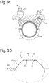
- the truncated cone has a circumferential surface 20 which is tapering, and which may be purely frusto-conical as indicated in Fig. 11(b) , or have a positive curvature as shown in Fig. 11 (a) or a negative curvature as shown in Fig. 11 (c) .
- a recess 22, complementary to the shape of the protrusion 19, is formed in the axle facing side 10 in the clamping region 9 of the trailing arm 2, as is illustrated in Fig. 5 .
- the protrusion 19 is received in the recess 22.
- the tapering surface 20 of the protrusion 19 is supported by a tapering surface 23 of the recess 22.
- the tapering surfaces 20 and 23 thus constitute support surfaces of the protrusion 19 and the recess 22 respectively in the first engagement area 13.
- the trailing arm is supported at the rear end of the clamping region 9 by the tapering surface of the protrusion 19. There is no engagement between the axle pad 2 and the axle facing side 10 of the trailing arm 5 in the vicinity of the protrusion 19 and the recess 22.
- the recess 22 is formed as a depression in the axle facing side 10 of the trailing arm 5.
- the trailing arm 10 is subjected during use to dynamic loads it is desirable to use a forming method without machining in which material is cut away. It is important that no sharp edges are created, which could lead to high stresses in the trailing arm material. From a strength point of view it is desired to maintain enough material to maintain the required strength.
- the first engagement area 13 is located at a rear end of the trailing arm facing side 11 of the axle pad 2.
- the protrusion 19 has a centre axis 21 (cf. Fig. 11 ), which seen from a lateral side coincides with the centre axis of the rear shanks 15 of the respective U-bolts 14 as can be seen in Figs 2 and 3 .
- the second engagement area 12 is located at a front end of the trailing arm facing side 11 of the axle pad 2.
- a ridge 25 is formed which defines a raised engagement surface 24.
- the engagement surface 24 is generally flat and engages the generally flat axle facing side 10 of the trailing arm 5 at the clamping region 9.
- the centre of the engagement surface 24 is preferably located at the same level, seen in the longitudinal direction, as the centre axis of the front shanks 15 of the U-bolts 14.
- the two engagement areas 12, 13 there is a gap 26 between the axle facing side 10 of the trailing arm 5 and the trailing arm facing side 11 of the axle pad 2.
- the two engagement areas 12, 13 provide a two point bearing between the axle pad 2 and the clamping region 9 of the trailing arm 5, which may be best seen in Fig. 3 .
- Figs 6 - 8 illustrate another embodiment of a clamping arrangement according to the invention.
- the structure of this embodiment is the generally the same as in the embodiment described in the above with reference to Figs 1-5 . Therefore, like parts have been indicated with the same reference numerals and for a description of those parts is referred to the above.
- This trailing arm 50 in Figs 6 - 8 has lateral ears 27 formed at the rear end of the clamping region 9.
- the lateral ears 27 are provided with through holes 28 through which the rear shanks 15 of the U-bolts can pass.
- the ears 27 thus constitute a counter element for the nuts 16 screwed on the rear shanks 15.
- a strap plate 17 is arranged as a counter element, like in the previous embodiment.
- a cross section is shown of the clamping arrangement of the embodiment of Fig 6-8 .
- This cross section is essentially the same as the one shown in Fig 3 .
- Fig. 10 is shown an enlarged view of the first engagement area 13 encircled in Fig. 9 .
- the protrusion 19 has a frusto-conical shape.
- This height of the gap 29 can vary, depending on the actual dimensions of the protrusion 19 and the recess 22, which include manufacturing tolerances in them.
- the base of the protrusion and of the recess may have a diameter D (cf. Fig. 15 ) with a tolerance of +/- 0,4 mm.
- the frusto-conical shape of the protrusion 19 and of the recess 22 allow for the compensation of these tolerances.
- a tolerance of +/- 0,4 mm leads through the distance L between the centre of the axle body 1 and the centre of the eyelet 6 to a height difference ⁇ h of the axis of the eyelet 6 of about +/- 1 mm, which is indicated in Fig. 15 .
- the tapering shape of the protrusion 19 has a peripheral surface 20 which extends obliquely with respect to the base of said tapering protrusion.
- the conical surface 20 extends under an angle ⁇ with respect to the normal 21 of said base as can be seen in Fig. 12 .
- the angle ⁇ between the normal 21 of said base and the peripheral surface 20 is preferably within the range 10° ⁇ ⁇ ⁇ 60°, such that tolerances can be sufficiently compensated.
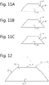
- a trailing arm 51 is shown which is similar to the trailing arm 50 of Fig. 8 .
- this trailing arm 51 there are longitudinal slots 52, 53 formed in the axle body facing surface of the trailing arm 51, which slots 52, 53 adjoin the recess 22.
- Fig. 13 a clamping arrangement of a different wheel axle suspension.
- This wheel axle suspension includes a trailing arm 55 which is curved at its clamping region 59.
- This trailing arm 55 has at the rear end a mounting portion 57 for an air spring which is on a lower level than the front end of the trailing arm, the axle pad 62 in this embodiment is formed conform to the shape of the trailing arm as a curved plate body.
- a tapering protrusion 19 is formed similar to the protrusions 19 described in the above and for example shown in Fig. 11 (a) - (c) .
- the protrusion 19 in the first engagement area has a centre axis 63
- the flat support surface 64 of the axle pad 62 in the second engagement area has a normal 65.
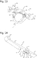
- Figs. 16 and 17 is shown a part of a wheel axle suspension with another embodiment of the axle pad.
- the axle pad 2 has two lateral lugs 30 which extend from the axle pad upwardly along the respective lateral sides of the trailing arm 5.
- the lateral lugs 30 provide a lateral interlocking between the trailing arm 5 and the axle pad 2.
- the lateral lugs 30 are formed on the axle pad 2 just rearwardly from the engagement surface 24.
- the lugs are formed more to the front, longitudinally seen at the level of the engagement surface 24.
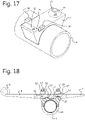
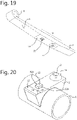
- Figs 18 - 20 An alternative embodiment is illustrated by Figs 18 - 20 .
- the axle pad 2 has instead of the lateral lugs 30 (cf. Fig. 17 ) a central lug 32 which protrudes from an upper side of the axle pad 2.
- the lug 32 is located behind the engagement surface 24.
- the lug 32 is square, but it may have another shape.
- the lug 32 is received in a corresponding recess 33 in the axle facing side 10 of the clamping region 9 of the trailing arm 5.
- the recess 33 can be pressed in the surface of the axle facing side 10.
- the recess 33 has in the longitudinal direction of the trailing arm 5 a larger length than the lug 32 as can be seen in Fig. 18 .
- the recess 33 has a depth such that there remains a gap between the top of the lug 32 and the bottom of the recess, which can also be recognised in Fig. 18 . Only the lateral sides 32A of the lug 32 fit narrowly, i.e. with a narrow gap, in the recess 33, such that the protrusion and recess 33 provide a lateral interlocking between the axle pad 2 and the trailing arm 5.
Landscapes
- Engineering & Computer Science (AREA)
- Mechanical Engineering (AREA)
- Vehicle Body Suspensions (AREA)
Description
- The invention relates to the field of (air) sprung wheel axle suspensions commonly applied on utility vehicles such as trucks, trailers or semi-trailers.
- In particular the invention relates to an axle clamping arrangement according to the preamble of
claim 1. - Wheel axle suspensions with axle clamping arrangements of this type are well known in the art. The trailing arm, the axle pad and the axle body are firmly clamped together by means of the tensioning means, whereby in engagement areas the frictional force should fix the axle body to the trailing arm. However, the frictional force alone is generally not sufficient to entirely keep the dynamically loaded trailing arm and the axle pad together, which may lead to shifting of the axle pad (and thus the axle body) with respect to the trailing arm. This shifting is undesirable because it leads to dislocation of the axle body with respect to the trailing arms, which may lead to extensive wear of tires, parts and even failure of parts. Therefore in such clamping arrangements there is often used an interlocking means to interlock, i.e. positive locking, the axle pad and the trailing arm in the longitudinal and transverse direction of the trailing arm. This interlocking means often is a pin like member attached to the axle pad and received in a recess in the trailing arm. Such an element may also be used to position the axle pad on the trailing arm.
- For example
DE 10 2012 103 961 A1 discloses an axle clamping arrangement comprising a tubular axle body, a trailing arm that crosses the axle body and an axle pad that is clamped between the axle body and the trailing arm. The assembly of trailing arm, axle pad and axle body is clamped together by U-bolts which extend around the axle body and which are tightened by nuts relative to a plate lying on the opposite side of the trailing arm. When the axle pad and the trailing arm are clamped together, the interface between them is defined by two engagement areas, one at the front end of the axle pad and one at the rear end of the axle pad, which engagement areas are indicated by "A" and "B" inFig. 3 of this document. In the engagement areas A and B the clamping forces are transmitted between the trailing arm and the axle pad. The interfaces in the engagement areas A and B lie in the same plane (or at least a plane with the same normal direction) and only provide a non-positive locking, which in general is not sufficient to prevent shifting of the trailing arm and axle pad with respect to each other. Therefore, in the engagement areas A and B the axle pad is provided with two protrusions and the trailing arm is provided with two blind holes which receive the respective protrusions of the axle pad to interlock the axle pad with respect to the trailing arm in a positive connection. This interlocking on two locations prevents relative shifting and rotation of the axle pad and the trailing arm in the plane defined by the interface between the trailing arm and the axle pad. - Another example of such a clamping arrangement is disclosed in
EP 1273464 . In this example the axle pad is provided with one positioning protrusion, approximately in the middle between the legs of the U-bolts, which protrusion closely fits in a blind hole provided in the trailing arm. - Yet another example of such a clamping arrangement is disclosed in
DE 10 2009 030 633 A1 . In this example the axle pad and the trailing arm are both provided with a blind hole between the legs of the U-bolts, in which a dowel is inserted to provide a correct longitudinal positioning of the axle pad (and thus the axle) on the trailing arm. Additionally the axle pad in this known clamping arrangement has at the front end and at the rear end lateral upstanding formations extending upward along either lateral side of the trailing arm. These lateral upstanding formations interlock the trailing arm and the axle pad in a transverse direction of the trailing arm. - A disadvantage of the known axle clamping arrangement is that the interlocking means and/or the corresponding recesses (such as blind holes) have to fit accurately, which generally requires a well-defined machining operation to remove tolerances in the parts. However, such machining operations, especially on the dynamically loaded trailing arm have a negative effect on the strength of the part. Moreover, the machining of parts leads to additional handling and costs.
-
EP 1334848 A1 discloses a clamping arrangement wherein there is three point bearing between the axle pad and the trailing arm. -
WO2012/078031 discloses a clamping arrangement with a three point bearing between the axle pad and the trailing arm. Also a clamping arrangement with a two point bearing bracket is shown, which may be considered the closest prior art for the invention. However, with this known two point bearing bracket the axle body also directly bears against the trailing arm. The influence of fabrication tolerances is mitigated by these embodiments. - The invention has for an object to provide an axle clamping arrangement in which the parts do not have to be machined to provide the interlocking structure.
- This object is achieved by an axle clamping arrangement according to
claim 1. - In the clamping arrangement of the invention the tapering protrusion provides a supporting area in which the axle pad is clamped against the tapering surface of the complementary recess. Since the surface is tapering, the structure when clamped together is able to compensate for manufacturing tolerances in both the trailing arm and the axle pad. Consequently no machining of parts is necessary, which makes the manufacturing easier and more cost effective. Moreover the circumferential tapering surface provides a non-positive locking ("kraftschlüssig") in the rotational direction of the protrusion. In the longitudinal and transverse direction of the trailing arm the tapering shape of the recess and the protrusion provides a combination of a positive locking ("formschlüssig") and non-positive locking ("kraftschlüssig"). The first engagement area and the second engagement area provide a two point bearing between the axle pad and the clamping region of the trailing arm.
- In a practical embodiment the tapering protrusion has a base which has a width or a diameter which is at least 30% of the width of the trailing arm at the location of the clamping arrangement, preferably 50% or more. In this way it is assured that the support surface is large enough to distribute the clamping forces to be transmitted between the axle pad and the trailing arm at the first engagement area.
- The tapering shape of the protrusion has a tapering circumferential surface which extends obliquely with respect to the base of the tapering protrusion. In a particular practical embodiment the tapering circumferential surface extends under an angle α with respect to the normal of the base, wherein the angle α between the normal of said base and the
peripheral surface 10° < α < 60°. - In a preferred embodiment the protrusion is formed on the axle pad and the recess is formed, preferably as a depression, into the trailing arm. The axle pad is often a cast or forged part, on which the protrusion can be formed easily. Trailing arms, in particular flexible trailing arms are often made from spring steel by a rolling process. After the arm is rolled it is easier to provide a depression than a protrusion in such a rolled arm. However flexible trailing arms can also be made by forging in which it would be possible to provide a tapering protrusion on the trailing arm.
- The protrusion may have different shapes. In a particular embodiment it has for example a round and tapering shape, preferably a frusto-conical shape, and the recess has a complementary round and tapering shape. The tapering surface of the frusto-conical shape may be purely conical, but it may also have a negative curvature or a positive curvature. In the latter case the protrusion may even be a spherical segment.
- Instead of round and tapering shape, the protrusion may also have a polygonal and tapering shape, and the recess in that case has a complementary polygonal and tapering shape. In a practical embodiment the polygonal and tapering shape is a truncated square pyramid shape. Also in this embodiment the sides of the truncated pyramid may be positively curved, negatively curved or plane.
- In a preferred embodiment the clamping arrangement comprises a second engagement area in which a generally flat support surface of the axle pad and a generally flat support surface of the trailing arm are clamped in engagement with each other, wherein, seen in the longitudinal direction of the trailing arm, the second engagement area is spaced apart from the first engagement area. More preferably the second engagement area is located in front of the first engagement area.
- In a practical embodiment the tensioning means comprise tensioning shanks, wherein at a front end region of the axle pad at least one front shank of said tensioning shanks and at a rear end region of the axle pad at least one rear shank of said tensioning shanks is located.
- The first and second engagement regions are located near the front and rear shanks, such that the clamping forces are guided efficiently into the engagement surfaces.
- In a preferred embodiment the first engagement area is located substantially at the rear end region of the axle pad (i.e. at or near the rear shanks), seen in the longitudinal direction of the trailing arm and the second engagement area is located substantially at the front end region of the axle pad (i.e. at or near the front shanks).
- In a further embodiment the protrusion in the first engagement area has a centre axis which is, seen in the longitudinal direction of the trailing arm, at the same level as the centre axis of the at least one rear shank.
- The tensioning means may have several practical embodiments. The most common tensioning means used are bolts and U-bolts which have threaded shanks and cooperate with an associated threaded nut.
- In a possible embodiment the tensioning means may comprise multiple bolts each including one of said threaded shanks. In such an embodiment a clamping body may be applied on a side of the axle body opposite the axle pad and is engaged by the bolts. Such a clamping body is as such known and may alternatively also be used with U-bolts, wherein the U-bolts extend around the clamping body, or around hooking formations formed on the clamping body.
- In another possible embodiment the tensioning means comprise one or more U-bolts each having two of said threaded shanks. In a further preferred embodiment the U-bolt extends around the axle body, such that the U-bolt has a front shank and a rear shank, which extend along a front side and a rear side of the axle body.
- The protrusion in the first engagement area has a centre axis, and the flat support surface of the axle pad in the second engagement area has a normal. The centre axis of the protrusion and said normal may extend under an angle β with respect to each other, preferably in the range 0° ≤ β ≤ 90°. When the angle β = 0°, the mentioned centre axis and the mentioned normal extend parallel to each other. In wheel axle suspensions where the trailing arm is curved at the clamping region, for example where the trailing arm has at the rear end a mounting portion for an air spring which is on a lower level than the front end of the trailing arm, the axle pad is formed conform to the shape of the trailing arm as a curved or angled plate body. In that event the angle β > 0° and may be as large as 90°.
- Notwithstanding the above there are embodiments possible wherein the angle β < 0°. In practise when the angle β remains small, but to a maximum of -45°.
- In a possible embodiment the axle pad has two lateral lugs which extend from the axle pad upwardly along respective lateral sides of the trailing arm and which provide a lateral interlocking between the trailing arm and the axle pad. In an alternative embodiment the axle pad has at least one lug extending upwardly from the axle pad, and wherein the trailing arm has at least one corresponding recess in the axle facing side thereof, which at least one lug and recess provide a lateral interlocking between the trailing arm and the axle pad. The lug(s) provide(s) a transverse interlocking at a location remote from the tapering protrusion, such that especially when the tapering protrusion has a round shape, e.g. a truncated cone shape, the axle pad is blocked by the lugs to rotate around the centre axis of the protrusion.
- The invention also relates to a (air) sprung wheel axle suspension including a clamping arrangement as described in the above.
- It is noted that an axle pad as intended herein and mentioned in the appended claims is a part that is arranged between the axle body and the trailing arm. The tensioning means clamp the axle body in the axle seat formed in the axle pad. The axle pad is clamped against the trailing arm. The axle body is thus not clamped directly against the trailing arm.
- The invention will be further elucidated in the following detailed description with reference to the drawing, in which:
-
Fig. 1 shows in a view in perspective a part of a wheel axle suspension with an embodiment of an axle clamping arrangement according to the invention, -
Fig. 2 shows in a side elevational view the part of the wheel axle suspension ofFig. 1 , -
Fig. 3 shows the side elevational view ofFig. 2 partly in cross-section, -
Fig. 4 shows in a view in perspective from above part of the axle body with the axle pad of the wheel axle suspension ofFig. 1 , -
Fig. 5 shows in a view in perspective from below a trailing arm of the wheel axle suspension ofFig. 1 , -
Fig. 6 shows in a view in perspective a part of a wheel axle suspension with another trailing arm with an embodiment of an axle clamping arrangement according to the invention, -
Fig. 7 shows in a side elevational view the part of the wheel axle suspension ofFig. 6 , -
Fig. 8 shows in a view in perspective from below the trailing arm of the wheel axle suspension ofFig. 6 , -
Fig. 9 shows a cross section of the clamping arrangement ofFig. 6 , -
Fig. 10 shows a detail of the cross section ofFig. 9 including a tapering protrusion, -
Fig. 11 (a) - (c) show cross sections of different shapes of the protrusion ofFig. 10 , -
Fig. 12 shows a cross section of the protrusion with indication of the inclination of the peripheral surface of the protrusion ofFig .10 , -
Fig. 13 shows a cross section of a clamping arrangement of a different wheel axle suspension, -
Fig. 14 shows in a view in perspective from below an alternative trailing arm of the wheel axle suspension ofFig. 6 , -
Fig. 15 shows the view ofFig. 3 with indication of the tolerances on dimension of the clamping arrangement, and -
Fig. 16 shows in a side elevational view partly in cross section a part of a wheel axle suspension with another embodiment of an axle clamping arrangement according to the invention, -
Fig. 17 shows in a view in perspective from above part of the axle body with the axle pad of the wheel axle suspension ofFig. 16 , -
Fig. 18 shows in a side elevational view partly in cross section a part of a wheel axle suspension with yet another embodiment of an axle clamping arrangement according to the invention, -
Fig. 19 shows in a view in perspective from below a trailing arm of the wheel axle suspension ofFig. 18 , and -
Fig. 20 shows in a view in perspective from above part of the axle body with the axle pad of the wheel axle suspension ofFig. 18 . - In
Fig. 1 and 2 is shown a part of a wheel axle suspension for a utility vehicle such as a trailer, semi-trailer or a truck. Such a wheel axle suspension comprises anaxle body 1, in this case atubular axle body 1 with a circular cross section. In other possible embodiments the axle body may also have another cross section, for example rectangular, which is not shown in the figures. At the ends of theaxle body 1, the vehicle wheels and other components can be mounted. - The
axle body 1 is suspended from a vehicle chassis by trailingarms 5. InFig. 1 there is shown only one trailingarm 5, but in an air sprung wheel axle suspension, there are generally two substantially parallel trailingarms 5, one at either lateral side of the vehicle, which are connected to theaxle body 1. The trailingarms 5 extend in the longitudinal direction of the vehicle. - At a front end portion of the trailing
arm 5 aneyelet 6 is formed by which the trailingarm 5 can be pivotally connected to a carrying bracket of the vehicle chassis (not shown). At arear end portion 7 of the trailingarm 5 an air spring (not shown) may be mounted, which air spring at an upper end thereof supports the vehicle chassis. This is all common for the skilled person in the field of sprung wheel axle suspensions and will not be further elaborated here. The trailingarm 5 in the shown embodiment is a so called flexible trailing arm, which has aspring portion 8 acting as a leaf spring. Thespring portion 8 extends rearwardly from theeyelet 6. In general such flexible trailing arms are made of spring steel by means of a rolling process to give the spring portion 8 a parabolic thickness taper toward the front end. Also flexible trailing arms having a non-parabolic thickness taper and a width taper are possible. Flexible trailing arms can also be made in other ways, such as for example by forging. Also flexible trailing arms made of composite materials are contemplated. - To position the
axle body 1 with respect to the trailingarms 5 anaxle pad 2 is provided, which is arranged between theaxle body 1 and the trailingarm 5 at aclamping region 9 of the latter. The clampingregion 9 of the trailing arm integrally adjoins thespring portion 8 at a rear end thereof. - The
axle pad 2 is typically a metal cast part, but may also be made in another way. Theaxle pad 2 has anaxle seat 3 formed in it, which provides anengagement surface 4 against which part of the circumference of a longitudinal section of theaxle body 1 is clamped. Theaxle body 1 is thus only supported by theaxle pad 2 and there is no direct contact between theaxle body 1 and the trailingarm 5. - As can be best seen in
Figs 3 - 5 , theside 11 of theaxle pad 2 opposite theaxle seat 3, i.e. in the shown example the upper side of theaxle pad 2, is facing the trailingarm 5 and is arranged against anaxle facing side 10 of the clampingregion 9 of the trailingarm 5. The trailingarm 5 extends crosswise with respect to theaxle body 1. Theaxle pad 2 has on this trailing arm facing side 11 afirst engagement area 13 and asecond engagement area 12 where theaxle pad 2 engages theaxle facing side 10 of the trailingarm 5. - In the shown example, the tensioning means for clamping the trailing
arm 5, theaxle pad 2 and theaxle body 1 together comprise two U-bolts 14, each located laterally from the trailingarm 5 and extending around theaxle body 1. Theshanks 15 of the U-bolts 14 have threaded end portions adapted to screw threaded nuts 16 on. On theside 18 of the clamping region of the trailingarm 5, which is facing away from theaxle body 1, i.e. in this example the upper side of the clampingregion 9, twostrap plates 17 extend transversely over the trailingarm 5. Theshanks 15 of the respective U-bolts 14 extend upwardly along a lateral side of the trailingarm 5 and extend through holes provided in therespective strap plates 17. When tightening the nuts 16 on theshanks 15, thestrap plates 17 function as counter elements and the U-bolts 14 are tensioned and a clamping force results to clamp theaxle body 1, theaxle pad 2 and the trailingarm 5 together. - As mentioned the
axle pad 2 engages the trailingarm 5 at theengagement areas axle pad 2. - In the embodiment shown the
first engagement area 13 of theaxle pad 2 includes a taperingprotrusion 19 which is, in a preferred embodiment formed as a truncated cone. The truncated cone has acircumferential surface 20 which is tapering, and which may be purely frusto-conical as indicated inFig. 11(b) , or have a positive curvature as shown inFig. 11 (a) or a negative curvature as shown inFig. 11 (c) . - A
recess 22, complementary to the shape of theprotrusion 19, is formed in theaxle facing side 10 in theclamping region 9 of the trailingarm 2, as is illustrated inFig. 5 . In the mounted state theprotrusion 19 is received in therecess 22. When the trailingarm 5 and theaxle pad 2 are clamped together the taperingsurface 20 of theprotrusion 19 is supported by a taperingsurface 23 of therecess 22. The tapering surfaces 20 and 23 thus constitute support surfaces of theprotrusion 19 and therecess 22 respectively in thefirst engagement area 13. As can be clearly derived fromFigs. 2 and3 the trailing arm is supported at the rear end of the clampingregion 9 by the tapering surface of theprotrusion 19. There is no engagement between theaxle pad 2 and theaxle facing side 10 of the trailingarm 5 in the vicinity of theprotrusion 19 and therecess 22. - It is preferred that the
recess 22 is formed as a depression in theaxle facing side 10 of the trailingarm 5. As the trailingarm 10 is subjected during use to dynamic loads it is desirable to use a forming method without machining in which material is cut away. It is important that no sharp edges are created, which could lead to high stresses in the trailing arm material. From a strength point of view it is desired to maintain enough material to maintain the required strength. - The
first engagement area 13 is located at a rear end of the trailingarm facing side 11 of theaxle pad 2. In the particular embodiment shown in theFigs 1 - 5 , theprotrusion 19 has a centre axis 21 (cf.Fig. 11 ), which seen from a lateral side coincides with the centre axis of therear shanks 15 of the respective U-bolts 14 as can be seen inFigs 2 and3 . - In the shown embodiment the
second engagement area 12 is located at a front end of the trailingarm facing side 11 of theaxle pad 2. In this second engagement area 12 aridge 25 is formed which defines a raisedengagement surface 24. Theengagement surface 24 is generally flat and engages the generally flataxle facing side 10 of the trailingarm 5 at the clampingregion 9. The centre of theengagement surface 24 is preferably located at the same level, seen in the longitudinal direction, as the centre axis of thefront shanks 15 of the U-bolts 14. - Between the two
engagement areas gap 26 between theaxle facing side 10 of the trailingarm 5 and the trailingarm facing side 11 of theaxle pad 2. Thus, the twoengagement areas axle pad 2 and the clampingregion 9 of the trailingarm 5, which may be best seen inFig. 3 . -
Figs 6 - 8 illustrate another embodiment of a clamping arrangement according to the invention. The structure of this embodiment is the generally the same as in the embodiment described in the above with reference toFigs 1-5 . Therefore, like parts have been indicated with the same reference numerals and for a description of those parts is referred to the above. - The difference between this embodiment of
Figs 6 - 8 and the embodiment ofFigs 1 - 5 is in the trailing arm. This trailingarm 50 inFigs 6 - 8 haslateral ears 27 formed at the rear end of the clampingregion 9. Thelateral ears 27 are provided with throughholes 28 through which therear shanks 15 of the U-bolts can pass. In this embodiment theears 27 thus constitute a counter element for the nuts 16 screwed on therear shanks 15. At the front end astrap plate 17 is arranged as a counter element, like in the previous embodiment. - In
Fig. 9 a cross section is shown of the clamping arrangement of the embodiment ofFig 6-8 . This cross section is essentially the same as the one shown inFig 3 . InFig. 10 is shown an enlarged view of thefirst engagement area 13 encircled inFig. 9 . In this enlarged view it is visible that theprotrusion 19 has a frusto-conical shape. It can be seen inFig. 10 that there is agap 29 between thetop surface 19a of the frusto-conical protrusion 19 and thebottom surface 22a of therecess 22. This height of thegap 29 can vary, depending on the actual dimensions of theprotrusion 19 and therecess 22, which include manufacturing tolerances in them. For example the base of the protrusion and of the recess may have a diameter D (cf.Fig. 15 ) with a tolerance of +/- 0,4 mm. The frusto-conical shape of theprotrusion 19 and of therecess 22 allow for the compensation of these tolerances. A tolerance of +/- 0,4 mm leads through the distance L between the centre of theaxle body 1 and the centre of theeyelet 6 to a height difference Δh of the axis of theeyelet 6 of about +/- 1 mm, which is indicated inFig. 15 . - The tapering shape of the
protrusion 19 has aperipheral surface 20 which extends obliquely with respect to the base of said tapering protrusion. In particular theconical surface 20 extends under an angle α with respect to the normal 21 of said base as can be seen inFig. 12 . The angle α between the normal 21 of said base and theperipheral surface 20 is preferably within therange 10° < α < 60°, such that tolerances can be sufficiently compensated. - In
Fig. 14 a trailingarm 51 is shown which is similar to the trailingarm 50 ofFig. 8 . In this trailingarm 51 there arelongitudinal slots 52, 53 formed in the axle body facing surface of the trailingarm 51, whichslots 52, 53 adjoin therecess 22. - In
Fig. 13 is shown a clamping arrangement of a different wheel axle suspension. This wheel axle suspension includes a trailingarm 55 which is curved at itsclamping region 59. This trailingarm 55 has at the rear end a mountingportion 57 for an air spring which is on a lower level than the front end of the trailing arm, theaxle pad 62 in this embodiment is formed conform to the shape of the trailing arm as a curved plate body. At the rear end a taperingprotrusion 19 is formed similar to theprotrusions 19 described in the above and for example shown inFig. 11 (a) - (c) . - The
protrusion 19 in the first engagement area has acentre axis 63, and theflat support surface 64 of theaxle pad 62 in the second engagement area has a normal 65. Thecentre axis 63 of theprotrusion 19 and said normal 65 extend under an angle β with respect to each other, in the example shown inFig. 13 the angle β = 45°. However, the angle may be in practise within a range 0° ≤ β ≤ 90°. When the angle β = 0°, the mentionedcentre axis 63 and the mentioned normal 65 extend parallel to each other, which results in the embodiment ofFig. 7 . - In
Figs. 16 and17 is shown a part of a wheel axle suspension with another embodiment of the axle pad. The difference with the embodiment shown inFigs 1 and 2 is that in this embodiment theaxle pad 2 has twolateral lugs 30 which extend from the axle pad upwardly along the respective lateral sides of the trailingarm 5. The lateral lugs 30 provide a lateral interlocking between the trailingarm 5 and theaxle pad 2. In the particular embodiment as is shown inFig. 16 the lateral lugs 30 are formed on theaxle pad 2 just rearwardly from theengagement surface 24. However, it is also possible that the lugs are formed more to the front, longitudinally seen at the level of theengagement surface 24. - An alternative embodiment is illustrated by
Figs 18 - 20 . In this embodiment theaxle pad 2 has instead of the lateral lugs 30 (cf.Fig. 17 ) acentral lug 32 which protrudes from an upper side of theaxle pad 2. Thelug 32 is located behind theengagement surface 24. In this case thelug 32 is square, but it may have another shape. Thelug 32 is received in acorresponding recess 33 in theaxle facing side 10 of the clampingregion 9 of the trailingarm 5. Therecess 33 can be pressed in the surface of theaxle facing side 10. Therecess 33 has in the longitudinal direction of the trailing arm 5 a larger length than thelug 32 as can be seen inFig. 18 . Furthermore, therecess 33 has a depth such that there remains a gap between the top of thelug 32 and the bottom of the recess, which can also be recognised inFig. 18 . Only the lateral sides 32A of thelug 32 fit narrowly, i.e. with a narrow gap, in therecess 33, such that the protrusion andrecess 33 provide a lateral interlocking between theaxle pad 2 and the trailingarm 5.
Claims (15)
- Vehicle axle clamping arrangement for a sprung wheel axle of a vehicle, in particular of a utility vehicle such as a truck, trailer or semi-trailer, the axle clamping arrangement comprising:- an axle body (1) extending in a transverse direction of the vehicle;- a trailing arm (5, 55) crossing the axle body (1) on an upper or lower side thereof;- an axle pad (2, 62) arranged between the trailing arm (5, 55) and the axle body (1), the axle pad (2, 62) having an axle seat (3) formed in it for receiving a longitudinal section of the axle body (1);- tensioning means (14, 16, 17) for clamping the trailing arm (5), the axle pad (2) and the axle body (1) together;wherein the axle body (1) is clamped only against an engagement surface (4) provided by the axle seat (3),characterized in that the axle clamping arrangement provides a two-point bearing between the axle pad (2, 62) and a clamping region (9, 59) of the trailing arm (5, 55), said two-point bearing being provided by a first engagement area (13) and a second engagement area (12) which are spaced apart from each other seen in the longitudinal direction of the trailing arm (5, 55), and in which, respectively, a support surface (20, 24, 64) of the axle pad (2, 62) and a support surface (10, 23) of the trailing arm (5, 55) are clamped in engagement with each other,wherein in the first engagement area (13) a tapering protrusion (19) is formed on one of the axle pad (2, 62) and the trailing arm (5, 55) and a complementary tapering recess (22) is formed on the other one of the axle pad (2, 62) and the trailing arm (5, 55) to receive said protrusion (19), said tapering surfaces of the protrusion (19) and of the recess (22) constituting the support surfaces in the first engagement area (13) where the axle pad (2, 62) and the trailing arm (5, 55) are clamped in engagement with each other, andwherein in the second engagement area (12) a generally flat support surface (24, 64) is formed on the axle pad (2, 62) and a generally flat support surface is formed (10) on the trailing arm (5, 55), said flat support surfaces (24, 10, 64) constituting the support surfaces in the second engagement area (12) where the axle pad (2, 62) and the trailing arm (5, 55) are clamped in engagement with each other.
- Axle clamping arrangement according to claim 1, wherein the protrusion (19) has a base which has a width or a diameter which is at least 30% of the width of the trailing arm (5, 55) at the location of the clamping region (9, 59).
- Axle clamping arrangement according to claim 1, wherein the protrusion (19) has a base which has a width or a diameter which is 50% or more of the width of the trailing arm (5, 55) at the location of the clamping region (9, 59).
- Axle clamping arrangement according to any of the claims 1-3, wherein the tapering shape of the protrusion (19) has a tapering surface (20) which extends obliquely with respect to a base of said tapering protrusion (19), in particular under an angle α with respect to the normal (21) of said base, wherein the angle α between the normal (21) of said base and the peripheral surface 10° < α < 60°.
- Axle clamping arrangement according to any of the claims 1-4, wherein the protrusion (19) in the first engagement area has a centre axis (63), and the flat support surface (64) of the axle pad (2) in the second engagement area (12) has a normal (65), wherein said centre axis (63) and said normal (65) extend under an angle β with respect to each other, wherein -45° ≤ β ≤ 90°, preferably 0° ≤ β ≤ 90°.
- Axle clamping arrangement according to any of the claims 1-5, wherein the protrusion (19) has a round and tapering shape, and the recess (22) has a complementary round and tapering shape.
- Axle clamping arrangement according to claim 6, wherein the round and tapering shape is a frusto-conical shape or a spherical segment (spherical frustum).
- Axle clamping arrangement according to claim 7, wherein:- the frusto-conical shape has a negative curvature; or- the frusto-conical shape has a positive curvature.
- Axle clamping arrangement according to claim 1-5, wherein the protrusion has a polygonal and tapering shape, and the recess has a complementary polygonal and tapering shape.
- Axle clamping arrangement according to claim 9, wherein the polygonal and tapering shape is a truncated square pyramid shape.
- Axle clamping arrangement according to any of the claims 1-10, wherein the protrusion (19) is formed on the axle pad (2, 62) and the recess (22) is formed into the trailing arm (5, 55).
- Axle clamping arrangement according to any of the claims 1-11, wherein the recess (22) is formed as a depression.
- Axle clamping arrangement according to any of the claims 1-12, wherein the tensioning means comprise tensioning shanks (15), wherein at a front end region of the axle pad (2, 62) at least one front shank (15) of said tensioning shanks (15) and at a rear end region of the axle pad (2, 62) at least one rear shank (15) of said tensioning shanks (15) is located, wherein, preferably, the tensioning shanks (15) are threaded shanks, and the tensioning means furthermore comprise nuts (16) adapted to cooperate with the threaded shanks (15).
- Axle clamping arrangement according to claim 13, wherein, seen in the longitudinal direction of the trailing arm (5, 55), the first engagement area (13) is located substantially at the rear end region of the axle pad (2, 62) and the second engagement area (12) is located substantially at the front end region of the axle pad (2, 62), wherein, preferably, the protrusion (19) in the first engagement area (13) has a centre axis (21), which is, seen in the longitudinal direction of the trailing arm (5), at the same level as the centre axis of the at least one rear shank (15).
- Sprung wheel axle suspension comprising an axle clamping arrangement according to any one of the preceding claims.
Applications Claiming Priority (2)
| Application Number | Priority Date | Filing Date | Title |
|---|---|---|---|
| NL2019987A NL2019987B1 (en) | 2017-11-28 | 2017-11-28 | Axle clamping arrangement |
| PCT/NL2018/050799 WO2019108062A1 (en) | 2017-11-28 | 2018-11-28 | Axle clamping arrangement |
Publications (2)
| Publication Number | Publication Date |
|---|---|
| EP3717286A1 EP3717286A1 (en) | 2020-10-07 |
| EP3717286B1 true EP3717286B1 (en) | 2022-04-13 |
Family
ID=61003329
Family Applications (1)
| Application Number | Title | Priority Date | Filing Date |
|---|---|---|---|
| EP18839909.1A Active EP3717286B1 (en) | 2017-11-28 | 2018-11-28 | Axle clamping arrangement |
Country Status (3)
| Country | Link |
|---|---|
| EP (1) | EP3717286B1 (en) |
| NL (1) | NL2019987B1 (en) |
| WO (1) | WO2019108062A1 (en) |
Families Citing this family (1)
| Publication number | Priority date | Publication date | Assignee | Title |
|---|---|---|---|---|
| CN115091907A (en) * | 2022-07-11 | 2022-09-23 | 东风汽车底盘系统有限公司 | Spring steel guide arm with mounting hole |
Citations (8)
| Publication number | Priority date | Publication date | Assignee | Title |
|---|---|---|---|---|
| US2539091A (en) | 1947-06-27 | 1951-01-23 | Frank E Linke | Spring mounting for automotive vehicles |
| EP0830957A2 (en) | 1996-09-19 | 1998-03-25 | Otto Sauer Achsenfabrik Keilberg | Clamp for an axle boday of a vehicle axle |
| DE29713996U1 (en) | 1997-08-06 | 1998-12-10 | Trenkamp & Gehle GmbH, 49413 Dinklage | Device for connecting the axle body of a wheel axle, in particular a commercial vehicle, to the trailing arms of an axle support |
| WO2010095924A1 (en) | 2009-02-17 | 2010-08-26 | Weweler Nederland B.V. | Support for pneumatic spring of wheel axle suspension. |
| WO2012078031A1 (en) | 2010-12-09 | 2012-06-14 | Vdl Weweler B.V. | Vehicle axle suspension, and vehicle comprising such vehicle axle suspension |
| US9050870B2 (en) | 2012-05-30 | 2015-06-09 | Hendrickson Usa, L.L.C. | Energy storing suspension components having retention recesses |
| EP2847012B1 (en) | 2012-05-07 | 2016-08-31 | BPW Bergische Achsen KG | Axle fixation for a sprung vehicle axle |
| DE102016013647A1 (en) | 2016-11-16 | 2017-05-11 | Daimler Ag | Clamping arrangement for a wheel axle of a commercial vehicle |
Family Cites Families (6)
| Publication number | Priority date | Publication date | Assignee | Title |
|---|---|---|---|---|
| NL1015231C2 (en) * | 2000-05-18 | 2001-11-20 | Weweler Nv | Connection between vehicle axle and wishbone. |
| NL1018435C2 (en) | 2001-07-02 | 2003-01-13 | Weweler Nv | Connection between an axle body of a wheel axle of a vehicle and a bearing arm carrying the wheel axle. |
| NL1019766C2 (en) * | 2002-01-17 | 2003-07-18 | Schmitz Cargobull Ag | Connection between vehicle axle and suspension arm. |
| US7066479B2 (en) * | 2003-04-23 | 2006-06-27 | Arvinmeritor Technology, Llc | Axle housing suspension seat assembly |
| EP2130688B1 (en) * | 2008-05-15 | 2011-04-27 | Weweler Nederland B.V. | Axle suspension of a vehicle. |
| DE102009030633A1 (en) | 2009-06-25 | 2010-12-30 | Bpw Bergische Achsen Kg | Axle connection for spring-loaded vehicle axles for e.g. lorry-trailer, has plate with opening that widens toward plate outer side to lug, where transmission of supporting forces of nut opposite plate exclusively takes place in lug |
-
2017
- 2017-11-28 NL NL2019987A patent/NL2019987B1/en active
-
2018
- 2018-11-28 EP EP18839909.1A patent/EP3717286B1/en active Active
- 2018-11-28 WO PCT/NL2018/050799 patent/WO2019108062A1/en not_active Ceased
Patent Citations (8)
| Publication number | Priority date | Publication date | Assignee | Title |
|---|---|---|---|---|
| US2539091A (en) | 1947-06-27 | 1951-01-23 | Frank E Linke | Spring mounting for automotive vehicles |
| EP0830957A2 (en) | 1996-09-19 | 1998-03-25 | Otto Sauer Achsenfabrik Keilberg | Clamp for an axle boday of a vehicle axle |
| DE29713996U1 (en) | 1997-08-06 | 1998-12-10 | Trenkamp & Gehle GmbH, 49413 Dinklage | Device for connecting the axle body of a wheel axle, in particular a commercial vehicle, to the trailing arms of an axle support |
| WO2010095924A1 (en) | 2009-02-17 | 2010-08-26 | Weweler Nederland B.V. | Support for pneumatic spring of wheel axle suspension. |
| WO2012078031A1 (en) | 2010-12-09 | 2012-06-14 | Vdl Weweler B.V. | Vehicle axle suspension, and vehicle comprising such vehicle axle suspension |
| EP2847012B1 (en) | 2012-05-07 | 2016-08-31 | BPW Bergische Achsen KG | Axle fixation for a sprung vehicle axle |
| US9050870B2 (en) | 2012-05-30 | 2015-06-09 | Hendrickson Usa, L.L.C. | Energy storing suspension components having retention recesses |
| DE102016013647A1 (en) | 2016-11-16 | 2017-05-11 | Daimler Ag | Clamping arrangement for a wheel axle of a commercial vehicle |
Also Published As
| Publication number | Publication date |
|---|---|
| WO2019108062A1 (en) | 2019-06-06 |
| NL2019987B1 (en) | 2019-06-05 |
| EP3717286A1 (en) | 2020-10-07 |
Similar Documents
| Publication | Publication Date | Title |
|---|---|---|
| CA2776799C (en) | Wheel axle suspension having clamp bodies with a protrusion for attaching an indented tubular axle to trailing arms | |
| EP1089889B1 (en) | Trailing arm axle/suspension system | |
| EP3461653B1 (en) | Axle clamping arrangement | |
| EP2398659B1 (en) | Support for pneumatic spring of wheel axle suspension. | |
| EP2648927B1 (en) | Vehicle axle suspension, and vehicle comprising such vehicle axle suspension | |
| EP3853049B1 (en) | Air-sprung wheel axle suspension of a vehicle with and bearing bracket for a trailing arm having a hammerhead | |
| EP3177468B1 (en) | Mounting of an axle lift | |
| US4618162A (en) | Device and method for adjusting camber in a strut-type vehicle suspension | |
| US8820760B2 (en) | Wheel axle suspension | |
| EP3717286B1 (en) | Axle clamping arrangement | |
| EP1980425B1 (en) | Width-varying suspension arm | |
| EP1970225A1 (en) | Strut arrangement for wheel axle suspension | |
| US20030163911A1 (en) | Method for attaching an axle to a leaf spring on a golf cart with hydraulic brakes | |
| EP3473457B1 (en) | Axle lift | |
| EP1580044A1 (en) | Connection between a wheel axle of a vehicle and a said wheel axle carrying trailing arm | |
| EP4263250B1 (en) | Trailing arm assembly | |
| EP0001337A1 (en) | A wheel mounting assembly | |
| GB2376218A (en) | Vehicle lift axles | |
| NL2008050C2 (en) | Wheel axle suspension. | |
| KR101339215B1 (en) | Rear suspension system | |
| JPH0444411Y2 (en) | ||
| AU2020248958A1 (en) | Axle fixation for a vehicle axle, and axle plate for same |
Legal Events
| Date | Code | Title | Description |
|---|---|---|---|
| STAA | Information on the status of an ep patent application or granted ep patent |
Free format text: STATUS: UNKNOWN |
|
| STAA | Information on the status of an ep patent application or granted ep patent |
Free format text: STATUS: THE INTERNATIONAL PUBLICATION HAS BEEN MADE |
|
| PUAI | Public reference made under article 153(3) epc to a published international application that has entered the european phase |
Free format text: ORIGINAL CODE: 0009012 |
|
| STAA | Information on the status of an ep patent application or granted ep patent |
Free format text: STATUS: REQUEST FOR EXAMINATION WAS MADE |
|
| 17P | Request for examination filed |
Effective date: 20200618 |
|
| AK | Designated contracting states |
Kind code of ref document: A1 Designated state(s): AL AT BE BG CH CY CZ DE DK EE ES FI FR GB GR HR HU IE IS IT LI LT LU LV MC MK MT NL NO PL PT RO RS SE SI SK SM TR |
|
| AX | Request for extension of the european patent |
Extension state: BA ME |
|
| DAV | Request for validation of the european patent (deleted) | ||
| DAX | Request for extension of the european patent (deleted) | ||
| GRAP | Despatch of communication of intention to grant a patent |
Free format text: ORIGINAL CODE: EPIDOSNIGR1 |
|
| STAA | Information on the status of an ep patent application or granted ep patent |
Free format text: STATUS: GRANT OF PATENT IS INTENDED |
|
| RIC1 | Information provided on ipc code assigned before grant |
Ipc: B60G 11/113 20060101AFI20210521BHEP Ipc: B60G 9/00 20060101ALI20210521BHEP Ipc: B60G 11/46 20060101ALI20210521BHEP |
|
| INTG | Intention to grant announced |
Effective date: 20210611 |
|
| GRAJ | Information related to disapproval of communication of intention to grant by the applicant or resumption of examination proceedings by the epo deleted |
Free format text: ORIGINAL CODE: EPIDOSDIGR1 |
|
| STAA | Information on the status of an ep patent application or granted ep patent |
Free format text: STATUS: REQUEST FOR EXAMINATION WAS MADE |
|
| INTC | Intention to grant announced (deleted) | ||
| GRAP | Despatch of communication of intention to grant a patent |
Free format text: ORIGINAL CODE: EPIDOSNIGR1 |
|
| STAA | Information on the status of an ep patent application or granted ep patent |
Free format text: STATUS: GRANT OF PATENT IS INTENDED |
|
| INTG | Intention to grant announced |
Effective date: 20211122 |
|
| GRAS | Grant fee paid |
Free format text: ORIGINAL CODE: EPIDOSNIGR3 |
|
| GRAA | (expected) grant |
Free format text: ORIGINAL CODE: 0009210 |
|
| STAA | Information on the status of an ep patent application or granted ep patent |
Free format text: STATUS: THE PATENT HAS BEEN GRANTED |
|
| AK | Designated contracting states |
Kind code of ref document: B1 Designated state(s): AL AT BE BG CH CY CZ DE DK EE ES FI FR GB GR HR HU IE IS IT LI LT LU LV MC MK MT NL NO PL PT RO RS SE SI SK SM TR |
|
| REG | Reference to a national code |
Ref country code: GB Ref legal event code: FG4D |
|
| REG | Reference to a national code |
Ref country code: CH Ref legal event code: EP |
|
| REG | Reference to a national code |
Ref country code: DE Ref legal event code: R096 Ref document number: 602018033921 Country of ref document: DE |
|
| REG | Reference to a national code |
Ref country code: IE Ref legal event code: FG4D |
|
| REG | Reference to a national code |
Ref country code: AT Ref legal event code: REF Ref document number: 1483124 Country of ref document: AT Kind code of ref document: T Effective date: 20220515 |
|
| REG | Reference to a national code |
Ref country code: LT Ref legal event code: MG9D |
|
| REG | Reference to a national code |
Ref country code: NL Ref legal event code: MP Effective date: 20220413 |
|
| REG | Reference to a national code |
Ref country code: AT Ref legal event code: MK05 Ref document number: 1483124 Country of ref document: AT Kind code of ref document: T Effective date: 20220413 |
|
| PG25 | Lapsed in a contracting state [announced via postgrant information from national office to epo] |
Ref country code: NL Free format text: LAPSE BECAUSE OF FAILURE TO SUBMIT A TRANSLATION OF THE DESCRIPTION OR TO PAY THE FEE WITHIN THE PRESCRIBED TIME-LIMIT Effective date: 20220413 |
|
| PG25 | Lapsed in a contracting state [announced via postgrant information from national office to epo] |
Ref country code: SE Free format text: LAPSE BECAUSE OF FAILURE TO SUBMIT A TRANSLATION OF THE DESCRIPTION OR TO PAY THE FEE WITHIN THE PRESCRIBED TIME-LIMIT Effective date: 20220413 Ref country code: PT Free format text: LAPSE BECAUSE OF FAILURE TO SUBMIT A TRANSLATION OF THE DESCRIPTION OR TO PAY THE FEE WITHIN THE PRESCRIBED TIME-LIMIT Effective date: 20220816 Ref country code: NO Free format text: LAPSE BECAUSE OF FAILURE TO SUBMIT A TRANSLATION OF THE DESCRIPTION OR TO PAY THE FEE WITHIN THE PRESCRIBED TIME-LIMIT Effective date: 20220713 Ref country code: LT Free format text: LAPSE BECAUSE OF FAILURE TO SUBMIT A TRANSLATION OF THE DESCRIPTION OR TO PAY THE FEE WITHIN THE PRESCRIBED TIME-LIMIT Effective date: 20220413 Ref country code: HR Free format text: LAPSE BECAUSE OF FAILURE TO SUBMIT A TRANSLATION OF THE DESCRIPTION OR TO PAY THE FEE WITHIN THE PRESCRIBED TIME-LIMIT Effective date: 20220413 Ref country code: GR Free format text: LAPSE BECAUSE OF FAILURE TO SUBMIT A TRANSLATION OF THE DESCRIPTION OR TO PAY THE FEE WITHIN THE PRESCRIBED TIME-LIMIT Effective date: 20220714 Ref country code: FI Free format text: LAPSE BECAUSE OF FAILURE TO SUBMIT A TRANSLATION OF THE DESCRIPTION OR TO PAY THE FEE WITHIN THE PRESCRIBED TIME-LIMIT Effective date: 20220413 Ref country code: ES Free format text: LAPSE BECAUSE OF FAILURE TO SUBMIT A TRANSLATION OF THE DESCRIPTION OR TO PAY THE FEE WITHIN THE PRESCRIBED TIME-LIMIT Effective date: 20220413 Ref country code: BG Free format text: LAPSE BECAUSE OF FAILURE TO SUBMIT A TRANSLATION OF THE DESCRIPTION OR TO PAY THE FEE WITHIN THE PRESCRIBED TIME-LIMIT Effective date: 20220713 Ref country code: AT Free format text: LAPSE BECAUSE OF FAILURE TO SUBMIT A TRANSLATION OF THE DESCRIPTION OR TO PAY THE FEE WITHIN THE PRESCRIBED TIME-LIMIT Effective date: 20220413 |
|
| PG25 | Lapsed in a contracting state [announced via postgrant information from national office to epo] |
Ref country code: RS Free format text: LAPSE BECAUSE OF FAILURE TO SUBMIT A TRANSLATION OF THE DESCRIPTION OR TO PAY THE FEE WITHIN THE PRESCRIBED TIME-LIMIT Effective date: 20220413 Ref country code: PL Free format text: LAPSE BECAUSE OF FAILURE TO SUBMIT A TRANSLATION OF THE DESCRIPTION OR TO PAY THE FEE WITHIN THE PRESCRIBED TIME-LIMIT Effective date: 20220413 Ref country code: LV Free format text: LAPSE BECAUSE OF FAILURE TO SUBMIT A TRANSLATION OF THE DESCRIPTION OR TO PAY THE FEE WITHIN THE PRESCRIBED TIME-LIMIT Effective date: 20220413 Ref country code: IS Free format text: LAPSE BECAUSE OF FAILURE TO SUBMIT A TRANSLATION OF THE DESCRIPTION OR TO PAY THE FEE WITHIN THE PRESCRIBED TIME-LIMIT Effective date: 20220813 |
|
| REG | Reference to a national code |
Ref country code: DE Ref legal event code: R026 Ref document number: 602018033921 Country of ref document: DE |
|
| PLBI | Opposition filed |
Free format text: ORIGINAL CODE: 0009260 |
|
| PLAX | Notice of opposition and request to file observation + time limit sent |
Free format text: ORIGINAL CODE: EPIDOSNOBS2 |
|
| PG25 | Lapsed in a contracting state [announced via postgrant information from national office to epo] |
Ref country code: SM Free format text: LAPSE BECAUSE OF FAILURE TO SUBMIT A TRANSLATION OF THE DESCRIPTION OR TO PAY THE FEE WITHIN THE PRESCRIBED TIME-LIMIT Effective date: 20220413 Ref country code: SK Free format text: LAPSE BECAUSE OF FAILURE TO SUBMIT A TRANSLATION OF THE DESCRIPTION OR TO PAY THE FEE WITHIN THE PRESCRIBED TIME-LIMIT Effective date: 20220413 Ref country code: RO Free format text: LAPSE BECAUSE OF FAILURE TO SUBMIT A TRANSLATION OF THE DESCRIPTION OR TO PAY THE FEE WITHIN THE PRESCRIBED TIME-LIMIT Effective date: 20220413 Ref country code: EE Free format text: LAPSE BECAUSE OF FAILURE TO SUBMIT A TRANSLATION OF THE DESCRIPTION OR TO PAY THE FEE WITHIN THE PRESCRIBED TIME-LIMIT Effective date: 20220413 Ref country code: DK Free format text: LAPSE BECAUSE OF FAILURE TO SUBMIT A TRANSLATION OF THE DESCRIPTION OR TO PAY THE FEE WITHIN THE PRESCRIBED TIME-LIMIT Effective date: 20220413 Ref country code: CZ Free format text: LAPSE BECAUSE OF FAILURE TO SUBMIT A TRANSLATION OF THE DESCRIPTION OR TO PAY THE FEE WITHIN THE PRESCRIBED TIME-LIMIT Effective date: 20220413 |
|
| 26 | Opposition filed |
Opponent name: SAF-HOLLAND GMBH Effective date: 20230113 |
|
| PG25 | Lapsed in a contracting state [announced via postgrant information from national office to epo] |
Ref country code: AL Free format text: LAPSE BECAUSE OF FAILURE TO SUBMIT A TRANSLATION OF THE DESCRIPTION OR TO PAY THE FEE WITHIN THE PRESCRIBED TIME-LIMIT Effective date: 20220413 |
|
| PLBP | Opposition withdrawn |
Free format text: ORIGINAL CODE: 0009264 |
|
| PG25 | Lapsed in a contracting state [announced via postgrant information from national office to epo] |
Ref country code: SI Free format text: LAPSE BECAUSE OF FAILURE TO SUBMIT A TRANSLATION OF THE DESCRIPTION OR TO PAY THE FEE WITHIN THE PRESCRIBED TIME-LIMIT Effective date: 20220413 |
|
| PLBB | Reply of patent proprietor to notice(s) of opposition received |
Free format text: ORIGINAL CODE: EPIDOSNOBS3 |
|
| PG25 | Lapsed in a contracting state [announced via postgrant information from national office to epo] |
Ref country code: MC Free format text: LAPSE BECAUSE OF FAILURE TO SUBMIT A TRANSLATION OF THE DESCRIPTION OR TO PAY THE FEE WITHIN THE PRESCRIBED TIME-LIMIT Effective date: 20220413 |
|
| REG | Reference to a national code |
Ref country code: CH Ref legal event code: PL |
|
| GBPC | Gb: european patent ceased through non-payment of renewal fee |
Effective date: 20221128 |
|
| REG | Reference to a national code |
Ref country code: BE Ref legal event code: MM Effective date: 20221130 |
|
| PG25 | Lapsed in a contracting state [announced via postgrant information from national office to epo] |
Ref country code: LI Free format text: LAPSE BECAUSE OF NON-PAYMENT OF DUE FEES Effective date: 20221130 Ref country code: CH Free format text: LAPSE BECAUSE OF NON-PAYMENT OF DUE FEES Effective date: 20221130 |
|
| PG25 | Lapsed in a contracting state [announced via postgrant information from national office to epo] |
Ref country code: LU Free format text: LAPSE BECAUSE OF NON-PAYMENT OF DUE FEES Effective date: 20221128 |
|
| PG25 | Lapsed in a contracting state [announced via postgrant information from national office to epo] |
Ref country code: IE Free format text: LAPSE BECAUSE OF NON-PAYMENT OF DUE FEES Effective date: 20221128 Ref country code: GB Free format text: LAPSE BECAUSE OF NON-PAYMENT OF DUE FEES Effective date: 20221128 |
|
| PLBD | Termination of opposition procedure: decision despatched |
Free format text: ORIGINAL CODE: EPIDOSNOPC1 |
|
| REG | Reference to a national code |
Ref country code: DE Ref legal event code: R100 Ref document number: 602018033921 Country of ref document: DE |
|
| PG25 | Lapsed in a contracting state [announced via postgrant information from national office to epo] |
Ref country code: FR Free format text: LAPSE BECAUSE OF NON-PAYMENT OF DUE FEES Effective date: 20221130 Ref country code: BE Free format text: LAPSE BECAUSE OF NON-PAYMENT OF DUE FEES Effective date: 20221130 |
|
| PG25 | Lapsed in a contracting state [announced via postgrant information from national office to epo] |
Ref country code: IT Free format text: LAPSE BECAUSE OF FAILURE TO SUBMIT A TRANSLATION OF THE DESCRIPTION OR TO PAY THE FEE WITHIN THE PRESCRIBED TIME-LIMIT Effective date: 20220413 |
|
| PLBM | Termination of opposition procedure: date of legal effect published |
Free format text: ORIGINAL CODE: 0009276 |
|
| 27C | Opposition proceedings terminated |
Effective date: 20231128 |
|
| PG25 | Lapsed in a contracting state [announced via postgrant information from national office to epo] |
Ref country code: CY Free format text: LAPSE BECAUSE OF FAILURE TO SUBMIT A TRANSLATION OF THE DESCRIPTION OR TO PAY THE FEE WITHIN THE PRESCRIBED TIME-LIMIT Effective date: 20220413 |
|
| PG25 | Lapsed in a contracting state [announced via postgrant information from national office to epo] |
Ref country code: MK Free format text: LAPSE BECAUSE OF FAILURE TO SUBMIT A TRANSLATION OF THE DESCRIPTION OR TO PAY THE FEE WITHIN THE PRESCRIBED TIME-LIMIT Effective date: 20220413 Ref country code: HU Free format text: LAPSE BECAUSE OF FAILURE TO SUBMIT A TRANSLATION OF THE DESCRIPTION OR TO PAY THE FEE WITHIN THE PRESCRIBED TIME-LIMIT; INVALID AB INITIO Effective date: 20181128 |
|
| PG25 | Lapsed in a contracting state [announced via postgrant information from national office to epo] |
Ref country code: MT Free format text: LAPSE BECAUSE OF FAILURE TO SUBMIT A TRANSLATION OF THE DESCRIPTION OR TO PAY THE FEE WITHIN THE PRESCRIBED TIME-LIMIT Effective date: 20220413 |
|
| PG25 | Lapsed in a contracting state [announced via postgrant information from national office to epo] |
Ref country code: BG Free format text: LAPSE BECAUSE OF FAILURE TO SUBMIT A TRANSLATION OF THE DESCRIPTION OR TO PAY THE FEE WITHIN THE PRESCRIBED TIME-LIMIT Effective date: 20220413 |
|
| PG25 | Lapsed in a contracting state [announced via postgrant information from national office to epo] |
Ref country code: BG Free format text: LAPSE BECAUSE OF FAILURE TO SUBMIT A TRANSLATION OF THE DESCRIPTION OR TO PAY THE FEE WITHIN THE PRESCRIBED TIME-LIMIT Effective date: 20220413 |
|
| PG25 | Lapsed in a contracting state [announced via postgrant information from national office to epo] |
Ref country code: TR Free format text: LAPSE BECAUSE OF FAILURE TO SUBMIT A TRANSLATION OF THE DESCRIPTION OR TO PAY THE FEE WITHIN THE PRESCRIBED TIME-LIMIT Effective date: 20220413 |
|
| PGFP | Annual fee paid to national office [announced via postgrant information from national office to epo] |
Ref country code: DE Payment date: 20251118 Year of fee payment: 8 |