EP1273464A1 - Connection between an axle beam of a wheel axle of a vehicle and a bearing arm supporting the wheel axle - Google Patents
Connection between an axle beam of a wheel axle of a vehicle and a bearing arm supporting the wheel axle Download PDFInfo
- Publication number
- EP1273464A1 EP1273464A1 EP02077599A EP02077599A EP1273464A1 EP 1273464 A1 EP1273464 A1 EP 1273464A1 EP 02077599 A EP02077599 A EP 02077599A EP 02077599 A EP02077599 A EP 02077599A EP 1273464 A1 EP1273464 A1 EP 1273464A1
- Authority
- EP
- European Patent Office
- Prior art keywords
- bearing arm
- axle beam
- supporting plate
- clamping
- axle
- Prior art date
- Legal status (The legal status is an assumption and is not a legal conclusion. Google has not performed a legal analysis and makes no representation as to the accuracy of the status listed.)
- Granted
Links
- 230000000284 resting effect Effects 0.000 claims description 2
- 239000006096 absorbing agent Substances 0.000 description 2
- 230000035939 shock Effects 0.000 description 2
- 230000000694 effects Effects 0.000 description 1
- 238000003754 machining Methods 0.000 description 1
Images


Classifications
-
- B—PERFORMING OPERATIONS; TRANSPORTING
- B60—VEHICLES IN GENERAL
- B60G—VEHICLE SUSPENSION ARRANGEMENTS
- B60G9/00—Resilient suspensions of a rigid axle or axle housing for two or more wheels
- B60G9/003—Resilient suspensions of a rigid axle or axle housing for two or more wheels the axle being rigidly connected to a trailing guiding device
-
- B—PERFORMING OPERATIONS; TRANSPORTING
- B60—VEHICLES IN GENERAL
- B60G—VEHICLE SUSPENSION ARRANGEMENTS
- B60G11/00—Resilient suspensions characterised by arrangement, location or kind of springs
- B60G11/02—Resilient suspensions characterised by arrangement, location or kind of springs having leaf springs only
- B60G11/10—Resilient suspensions characterised by arrangement, location or kind of springs having leaf springs only characterised by means specially adapted for attaching the spring to axle or sprung part of the vehicle
- B60G11/113—Mountings on the axle
-
- B—PERFORMING OPERATIONS; TRANSPORTING
- B60—VEHICLES IN GENERAL
- B60G—VEHICLE SUSPENSION ARRANGEMENTS
- B60G11/00—Resilient suspensions characterised by arrangement, location or kind of springs
- B60G11/32—Resilient suspensions characterised by arrangement, location or kind of springs having springs of different kinds
- B60G11/34—Resilient suspensions characterised by arrangement, location or kind of springs having springs of different kinds including leaf springs
- B60G11/46—Resilient suspensions characterised by arrangement, location or kind of springs having springs of different kinds including leaf springs and also fluid springs
- B60G11/465—Resilient suspensions characterised by arrangement, location or kind of springs having springs of different kinds including leaf springs and also fluid springs with a flexible wall
-
- B—PERFORMING OPERATIONS; TRANSPORTING
- B60—VEHICLES IN GENERAL
- B60G—VEHICLE SUSPENSION ARRANGEMENTS
- B60G2200/00—Indexing codes relating to suspension types
- B60G2200/30—Rigid axle suspensions
- B60G2200/31—Rigid axle suspensions with two trailing arms rigidly connected to the axle
-
- B—PERFORMING OPERATIONS; TRANSPORTING
- B60—VEHICLES IN GENERAL
- B60G—VEHICLE SUSPENSION ARRANGEMENTS
- B60G2202/00—Indexing codes relating to the type of spring, damper or actuator
- B60G2202/10—Type of spring
- B60G2202/11—Leaf spring
- B60G2202/112—Leaf spring longitudinally arranged
-
- B—PERFORMING OPERATIONS; TRANSPORTING
- B60—VEHICLES IN GENERAL
- B60G—VEHICLE SUSPENSION ARRANGEMENTS
- B60G2204/00—Indexing codes related to suspensions per se or to auxiliary parts
- B60G2204/10—Mounting of suspension elements
- B60G2204/14—Mounting of suspension arms
- B60G2204/148—Mounting of suspension arms on the unsprung part of the vehicle, e.g. wheel knuckle or rigid axle
-
- B—PERFORMING OPERATIONS; TRANSPORTING
- B60—VEHICLES IN GENERAL
- B60G—VEHICLE SUSPENSION ARRANGEMENTS
- B60G2204/00—Indexing codes related to suspensions per se or to auxiliary parts
- B60G2204/40—Auxiliary suspension parts; Adjustment of suspensions
- B60G2204/43—Fittings, brackets or knuckles
- B60G2204/4306—Bracket or knuckle for rigid axles, e.g. for clamping
-
- B—PERFORMING OPERATIONS; TRANSPORTING
- B60—VEHICLES IN GENERAL
- B60G—VEHICLE SUSPENSION ARRANGEMENTS
- B60G2204/00—Indexing codes related to suspensions per se or to auxiliary parts
- B60G2204/40—Auxiliary suspension parts; Adjustment of suspensions
- B60G2204/44—Centering or positioning means
-
- B—PERFORMING OPERATIONS; TRANSPORTING
- B60—VEHICLES IN GENERAL
- B60G—VEHICLE SUSPENSION ARRANGEMENTS
- B60G2204/00—Indexing codes related to suspensions per se or to auxiliary parts
- B60G2204/40—Auxiliary suspension parts; Adjustment of suspensions
- B60G2204/45—Stops limiting travel
- B60G2204/4504—Stops limiting travel using cable or band to prevent extension
-
- B—PERFORMING OPERATIONS; TRANSPORTING
- B60—VEHICLES IN GENERAL
- B60G—VEHICLE SUSPENSION ARRANGEMENTS
- B60G2206/00—Indexing codes related to the manufacturing of suspensions: constructional features, the materials used, procedures or tools
- B60G2206/01—Constructional features of suspension elements, e.g. arms, dampers, springs
- B60G2206/30—Constructional features of rigid axles
Definitions
- the present invention relates to a connection between an axle beam of a wheel axle of a vehicle and a bearing arm of the wheel axle extending in the longitudinal direction of the vehicle and intersecting the axle beam substantially at right angles, according to the preamble of claim 1.
- connection is known in many embodiments, for example from EP-A-0830957, for an axle beam of circular cross section, and from EP-A-0590528, for an axle beam of square cross section.
- the axle beam is usually fitted on the underside of the bearing arm.
- this increases the ride height of the vehicle, i.e. the distance between the underside of the chassis of the vehicle and the axle beam, since part of the space between the axle beam and the underside of the chassis is taken up by the bearing arm, and the space then remaining between the bearing arm and the underside of the chassis has to be sufficient to provide a spring travel for the wheel axle.
- the supporting plate is of a fairly heavy design and parts of the clamping means project above the bearing arm, so that these parts take up a relatively large amount of space on the top side of the bearing arm, the ride height is increased even further.
- the object of the invention is to provide a connection of the abovementioned type in the case of which with an axle beam fitted underneath the bearing arm the ride height of the vehicle is not much greater than with the axle beam fitted on the top side of the bearing arm.
- connection according to the invention is very stable and can be designed in such a way that the parts of the connection are relatively light and project as little as possible above the bearing arm, so that the ride height of the vehicle can remain limited.
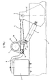
- Fig. 1 shows an air spring system for a wheel axle of a vehicle, in which the connection between the axle beam of circular cross section of the wheel axle and the bearing arm of the wheel axle is designed according to the invention.
- Fig. 1 the axle beam of the wheel axle is indicated by reference numeral 1.
- the air spring system illustrated comprises a bearing bracket 3 fixed on a chassis beam 2 of a vehicle, a bearing arm 5 fixed at the position of a fixing point 4 in a pivoting manner on the bearing bracket 3, an air bellows 7 fitted between the free end part of the bearing arm 5 that is situated at a distance from the fixing point 4 and the chassis beam, and a shock absorber 8 fitted between the bearing bracket 3 and the bearing arm 5.
- the bearing arm 5 intersects the axle beam 1 substantially at right angles.
- the axle beam 1 is fitted on the underside of the bearing arm and connected to the bearing arm 5 by means of a connection according to the invention to be described in further detail below, which connection is indicated in its entirety by reference numeral 10.
- the advantage of fitting the axle beam on the underside of the bearing arm 5 is that space is created for fitting a brake system, for example, on the axle beam.
- the invention is not limited to a system in which the axle beam is fitted on the underside of the bearing arm.
- connection 10 comprises an intermediate block (axle pad) 11 between the axle beam 1 and the bearing arm 5, which intermediate block is provided with a recess 12 in which the axle beam 1 rests, and is provided with two supporting plates 13 and 14, which are fitted on the bearing arm on the side of the bearing arm 5 facing away from the axle beam 1.
- connection 10 further comprises clamping elements in the form of two substantially U-shaped brackets 15 and 16, the free end parts 17 of which are provided with screw thread.
- the free end parts 17 of the U-shaped brackets 15 and 16 project through bores in the supporting plates 13 and 14 and are provided with nuts 18.
- the supporting plates 13 and 14, the bearing arm 5, the intermediate block 11 and the axle beam 1 are immovably connected to each other by means of the U-shaped brackets 15 and 16 with nuts 18.
- the intermediate block 11 can be connected to the axle beam 1 by means of a welded connection 19, in order to prevent the axle beam 1 from starting to rotate relative to the intermediate block.
- the intermediate block is further provided with a lug 20, which slots into a recess 21 in the bearing arm 5. In this way the intermediate block 11 is always positioned correctly relative to the bearing arm 5.
- the positioning of the intermediate block 11 relative to the bearing arm 5 can, however, also be achieved in a different way.
- each of the two supporting plates 13 and 14 can be provided with clamping parts 22 and 23, which extend on either side next to the bearing arm 5, and which are each provided with holes drilled through them, through which the free end parts 17 of the U-shaped brackets 15 and 16 extend.
- the clamping parts 22 and 23 are provided with supporting faces 24 and 25 for the nuts 18. These supporting faces 24 and 25 lie at a level that is such that the free end parts 17 with the nuts 18 of the U-shaped brackets 15 and 16 do not extend above the top side of the supporting plates 13 and 14. This means that the nuts 18 lie at a low level, and the space between the bearing arm and the chassis beam situated above the bearing arm can be used in the optimum manner as a spring path for the wheel axle.
- each supporting plate 13, 14 between the clamping parts 22, 23 is slightly deformable.
- the clamping parts 22, 23 rest with their free ends 27 on the side faces 28 of the intermediate block 11.
- said clamping parts 22, 23 can be clamped firmly on the intermediate block 11 with a limited tightening moment of the nuts 18.
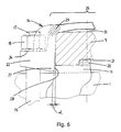
- the deformability of the part 26 can be achieved (see Figs. 3, 5 and 6) by making a transitional part 29 between the clamping parts 22, 23 and the remainder of the supporting plate 13, 14 slightly flexible and/or by making the part 26 slightly extensible.
- the latter is possible by providing the part 26 with a narrowed part 30 (Figs. 3 and 5) or by making the part 26 a curved shape (Fig. 6), so that a space 31 is created between the part 26 and the bearing arm 5.
- the bearing arm 5 and the supporting plates 13 and 14 can be calibrated.
- the side faces of the bearing arm 5 are then preferably bevelled at least over a part situated at the side of the supporting plate 13, 14, in order to be able to calibrate the width of the bearing arm 5 in a simple manner (see Figs. 5 and 6).
- the angle of bevel (clearance angle) ⁇ can be relatively small (a few degrees).
- the height of the bevelled part is preferably 1/3 - 1/2 of the height of the bearing arm 5.
- the shape of the faces of the clamping parts 22, 23 of the supporting plates 13, 14 interacting with the bearing arm 5 is preferably adapted to the shape of the bearing arm 5.
- connection according to the invention described above comprises two supporting plates 13, 14, which are situated in the longitudinal direction of the bearing arm 5 on either side of the axle beam 1, and which are each provided with two clamping parts 22, 23 extending on either side next to the bearing arm 5.
- connection comprises a single supporting plate that is provided with two or four clamping parts situated in pairs in the longitudinal direction of the bearing arm 5 on either side of the axle beam 1, and extending in pairs on either side of the bearing arm 5.
- connection according to the invention described above can also be used in a slightly adapted embodiment for an axle beam with a substantially rectangular or square cross section.
- the shock absorber 8 can be fixed to a supporting plate 13' by means of an additional bracket 32 on the supporting plate 13'.
- This additional bracket 32 is preferably asymmetrical relative to the longitudinal axis of the bearing arm 5, in other words fitted largely next to the bearing arm 5, so that when the bearing arm 5 moves upwards the additional bracket 32 does not go against the underside of the chassis beam 2, which would destroy the effect of the special design of the connection.
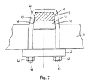
- FIG. 7 Another embodiment of a connection according to the invention is shown in Fig. 7.
- the axle beam 1 has a substantially rectangular or square cross section.
- connection between the axle beam 1 and the bearing arm 5 comprises an intermediate block (axle pad) 41 fitted between the axle beam 1 and the bearing arm, which intermediate block is provided with a recess in which the axle beam 1 rests, a supporting plate 42 that is fitted on the side facing away from the bearing arm 5 for the axle beam 1, and clamping elements in the form of two substantially U-shaped brackets 43 (only one visible in Fig. 7), which are fitted around the bearing arm 5 on either side of the axle beam 1.
- the free end parts 44 and 45 of the U-shaped brackets 43 project through bores in the supporting plate 42 and are provided with nuts 46 and 47.
- the U-shaped brackets form clamping parts which interact in a clamping manner with at least a part of the side faces 48 and 49 of the bearing arm 5 and at least a part of the side faces 50 and 51 of the intermediate block 41.
- the side faces 48, 49, 50 and 51 are preferably slightly bevelled, the shape of the U-shaped brackets 43 being adapted to them.
- connection shown in Fig. 7 can also be used in the case of an axle beam with a circular cross section.
- connection according to the invention is used in the case of an axle beam mounted on the underside of the bearing arm.
- the connection can, however, also be used in the case of an axle beam mounted on the top side of the bearing arm.
Landscapes
- Engineering & Computer Science (AREA)
- Mechanical Engineering (AREA)
- Vehicle Body Suspensions (AREA)
- Axle Suspensions And Sidecars For Cycles (AREA)
Abstract
Description
- The present invention relates to a connection between an axle beam of a wheel axle of a vehicle and a bearing arm of the wheel axle extending in the longitudinal direction of the vehicle and intersecting the axle beam substantially at right angles, according to the preamble of
claim 1. - Such a connection is known in many embodiments, for example from EP-A-0830957, for an axle beam of circular cross section, and from EP-A-0590528, for an axle beam of square cross section. In order to create sufficient space for a brake system, for example, the axle beam is usually fitted on the underside of the bearing arm. However, this increases the ride height of the vehicle, i.e. the distance between the underside of the chassis of the vehicle and the axle beam, since part of the space between the axle beam and the underside of the chassis is taken up by the bearing arm, and the space then remaining between the bearing arm and the underside of the chassis has to be sufficient to provide a spring travel for the wheel axle. If, in addition, as in the case of the known connections, the supporting plate is of a fairly heavy design and parts of the clamping means project above the bearing arm, so that these parts take up a relatively large amount of space on the top side of the bearing arm, the ride height is increased even further.
- The object of the invention is to provide a connection of the abovementioned type in the case of which with an axle beam fitted underneath the bearing arm the ride height of the vehicle is not much greater than with the axle beam fitted on the top side of the bearing arm.
- This object is achieved according to the invention by a connection according to
claim 1. - The connection according to the invention is very stable and can be designed in such a way that the parts of the connection are relatively light and project as little as possible above the bearing arm, so that the ride height of the vehicle can remain limited.
- Preferred embodiments of the connection according to the invention are described in the subclaims.
- The invention will be explained in greater detail in the exemplary embodiment below with reference to the drawing, in which:
- Fig. 1 shows an air spring system for a wheel axle of a vehicle, in which a specific embodiment of the connection according to the invention is used;
- Fig. 2 shows on an enlarged scale a slightly modified embodiment of a connection according to the invention;
- Fig. 3 shows a top view of the connection of Fig. 2;
- Fig. 4 shows a side view of the connection of Fig. 2;
- Fig. 5 shows a detail V of Fig. 4 on an enlarged scale;
- Fig. 6 shows in an illustration corresponding to Fig. 5 a slightly different embodiment of the connection according to the invention; and
- Fig. 7 shows yet another embodiment of a connection according to the invention.
-
- Fig. 1 shows an air spring system for a wheel axle of a vehicle, in which the connection between the axle beam of circular cross section of the wheel axle and the bearing arm of the wheel axle is designed according to the invention.
- In Fig. 1 the axle beam of the wheel axle is indicated by
reference numeral 1. The air spring system illustrated comprises abearing bracket 3 fixed on achassis beam 2 of a vehicle, abearing arm 5 fixed at the position of a fixing point 4 in a pivoting manner on thebearing bracket 3, anair bellows 7 fitted between the free end part of thebearing arm 5 that is situated at a distance from the fixing point 4 and the chassis beam, and ashock absorber 8 fitted between thebearing bracket 3 and thebearing arm 5. Thebearing arm 5 intersects theaxle beam 1 substantially at right angles. Theaxle beam 1 is fitted on the underside of the bearing arm and connected to thebearing arm 5 by means of a connection according to the invention to be described in further detail below, which connection is indicated in its entirety byreference numeral 10. - The advantage of fitting the axle beam on the underside of the
bearing arm 5 is that space is created for fitting a brake system, for example, on the axle beam. However, the invention is not limited to a system in which the axle beam is fitted on the underside of the bearing arm. - In the embodiments shown in Figs. 2 to 6 the
connection 10 comprises an intermediate block (axle pad) 11 between theaxle beam 1 and thebearing arm 5, which intermediate block is provided with arecess 12 in which theaxle beam 1 rests, and is provided with two supportingplates bearing arm 5 facing away from theaxle beam 1. - The
connection 10 further comprises clamping elements in the form of two substantially U-shapedbrackets free end parts 17 of which are provided with screw thread. Thefree end parts 17 of the U-shapedbrackets plates nuts 18. The supportingplates bearing arm 5, theintermediate block 11 and theaxle beam 1 are immovably connected to each other by means of theU-shaped brackets nuts 18. - The
intermediate block 11 can be connected to theaxle beam 1 by means of awelded connection 19, in order to prevent theaxle beam 1 from starting to rotate relative to the intermediate block. At the side resting against thebearing arm 5, the intermediate block is further provided with alug 20, which slots into arecess 21 in thebearing arm 5. In this way theintermediate block 11 is always positioned correctly relative to thebearing arm 5. The positioning of theintermediate block 11 relative to thebearing arm 5 can, however, also be achieved in a different way. - As can be seen clearly in Figs. 4 - 6, each of the two supporting
plates clamping parts bearing arm 5, and which are each provided with holes drilled through them, through which thefree end parts 17 of theU-shaped brackets clamping parts faces nuts 18. These supportingfaces free end parts 17 with thenuts 18 of the U-shapedbrackets plates nuts 18 lie at a low level, and the space between the bearing arm and the chassis beam situated above the bearing arm can be used in the optimum manner as a spring path for the wheel axle. - The
part 26 of each supportingplate clamping parts nuts 18 have been tightened, theclamping parts free ends 27 on the side faces 28 of theintermediate block 11. Through the deformability of thepart 26, saidclamping parts intermediate block 11 with a limited tightening moment of thenuts 18. - The deformability of the
part 26 can be achieved (see Figs. 3, 5 and 6) by making atransitional part 29 between theclamping parts plate part 26 slightly extensible. The latter is possible by providing thepart 26 with a narrowed part 30 (Figs. 3 and 5) or by making the part 26 a curved shape (Fig. 6), so that aspace 31 is created between thepart 26 and thebearing arm 5. - In order to minimize the influence of tolerances, the
bearing arm 5 and the supportingplates bearing arm 5 are then preferably bevelled at least over a part situated at the side of the supportingplate bearing arm 5 in a simple manner (see Figs. 5 and 6). The angle of bevel (clearance angle) α can be relatively small (a few degrees). The height of the bevelled part is preferably 1/3 - 1/2 of the height of thebearing arm 5. - The shape of the faces of the
clamping parts plates bearing arm 5 is preferably adapted to the shape of thebearing arm 5. - It is also possible to calibrate a
bearing arm 5 with non-bevelled side faces. The side faces of thebearing arm 5 will then usually be subjected to a machining operation, such as grinding. - The embodiment of the connection according to the invention described above comprises two supporting
plates bearing arm 5 on either side of theaxle beam 1, and which are each provided with twoclamping parts bearing arm 5. - Another embodiment of the connection (not shown here) comprises a single supporting plate that is provided with two or four clamping parts situated in pairs in the longitudinal direction of the
bearing arm 5 on either side of theaxle beam 1, and extending in pairs on either side of thebearing arm 5. - The connection according to the invention described above can also be used in a slightly adapted embodiment for an axle beam with a substantially rectangular or square cross section.
- As shown in Fig. 1, the
shock absorber 8 can be fixed to a supporting plate 13' by means of anadditional bracket 32 on the supporting plate 13'. Thisadditional bracket 32 is preferably asymmetrical relative to the longitudinal axis of thebearing arm 5, in other words fitted largely next to thebearing arm 5, so that when thebearing arm 5 moves upwards theadditional bracket 32 does not go against the underside of thechassis beam 2, which would destroy the effect of the special design of the connection. - Another embodiment of a connection according to the invention is shown in Fig. 7. In Fig. 7 the
axle beam 1 has a substantially rectangular or square cross section. - The connection between the
axle beam 1 and thebearing arm 5 comprises an intermediate block (axle pad) 41 fitted between theaxle beam 1 and the bearing arm, which intermediate block is provided with a recess in which theaxle beam 1 rests, a supportingplate 42 that is fitted on the side facing away from thebearing arm 5 for theaxle beam 1, and clamping elements in the form of two substantially U-shaped brackets 43 (only one visible in Fig. 7), which are fitted around thebearing arm 5 on either side of theaxle beam 1. Thefree end parts brackets 43 project through bores in the supportingplate 42 and are provided withnuts - The U-shaped brackets form clamping parts which interact in a clamping manner with at least a part of the side faces 48 and 49 of the
bearing arm 5 and at least a part of the side faces 50 and 51 of the intermediate block 41. The side faces 48, 49, 50 and 51 are preferably slightly bevelled, the shape of the U-shapedbrackets 43 being adapted to them. - With a slightly adapted shape of the intermediate block and the supporting plate, the connection shown in Fig. 7 can also be used in the case of an axle beam with a circular cross section.
- In the above description the connection according to the invention is used in the case of an axle beam mounted on the underside of the bearing arm. The connection can, however, also be used in the case of an axle beam mounted on the top side of the bearing arm.
Claims (9)
- Connection between an axle beam of a wheel axle of a vehicle and a bearing arm of the wheel axle extending in the longitudinal direction of the vehicle and intersecting the axle beam substantially at right angles, comprising an intermediate block (axle pad) fitted between the axle beam and the bearing arm, which intermediate block is provided with a recess in which the axle beam rests, and comprising connecting means that comprise at least one supporting plate and clamping elements of the screw bolt type, which extend on either side of the bearing arm and the axle beam and through bores that are drilled through the supporting plate, which connecting means connect the bearing arm, the intermediate block and the axle beam immovably to each other, characterized in that the connecting means are provided with clamping parts situated on either side next to the bearing arm, each clamping part interacting in a clamping manner with at least a part of a side face of the bearing arm and at least a part of a side face of the intermediate block.
- Connection according to claim 1, in which the supporting plate is fitted on the bearing arm on the side of the bearing arm facing away from the axle beam, and is provided with parts projecting beyond the bearing arm on either side, which projecting parts are designed as the clamping parts situated on either side next to the bearing arm, each clamping part interacting in a clamping manner with the bearing arm at least over a part of a side face of the bearing arm that is situated on the side of the supporting plate, and each clamping part at the free end resting in a clamping manner on a side face of the intermediate block.
- Connection according to claim 2, in which the part of the supporting plate between the clamping parts is at least partially slightly deformable.
- Connection according to claim 2 or 3, in which the connection comprises two supporting plates situated in the longitudinal direction of the bearing arm on either side of the axle beam, each supporting plate being provided with two clamping parts extending on either side next to the bearing arm.
- Connection according to claim 2 or 3, in which the connection comprises one supporting plate that is provided with four clamping parts situated in the longitudinal direction of the bearing arm in pairs on either side of the axle beam, and extending in pairs on either side of the bearing arm.
- Connection according to one of claims 2 - 5, in which the clamping elements are composed of two substantially U-shaped brackets, which are fitted around the axle beam on either side of the bearing arm, and the free end parts of which are provided with screw thread and extend through bores that are drilled through the clamping parts of the supporting plate(s), nuts being screwed onto the parts of the free end parts of the brackets projecting beyond the supporting plate(s), which nuts rest upon supporting faces on the side of the clamping parts facing away from the axle beam, which supporting faces are situated at a level that is such that the free end parts with the nuts of the brackets are situated in the vertical direction below the level of the top side of the supporting plate(s).
- Connection according to claim 1, in which the supporting plate is fitted on the side of the axle beam facing away from the bearing arm, and the clamping elements are composed of two substantially U-shaped brackets, which are fitted around the bearing arm on either side of the axle beam, and the free end parts of which are provided with screw thread and extend through the bores that are drilled through the supporting plate, nuts being screwed onto the parts of the free end parts of the brackets projecting beyond the supporting plate, which nuts rest upon supporting faces on the side of the supporting plate facing away from the axle beam, and the legs of the U-shaped brackets being designed as the clamping parts situated on either side of the bearing arm.
- Connection according to one of claims 1 - 7, in which the side faces of the bearing arm are bevelled at least over a part of the height of the bearing arm situated on the side of the supporting plate.
- Connection according to claim 8, in which the side faces of the bearing arm are bevelled over approximately 1/3 - 1/2 of the height of the bearing arm.
Applications Claiming Priority (2)
| Application Number | Priority Date | Filing Date | Title |
|---|---|---|---|
| NL1018435 | 2001-07-02 | ||
| NL1018435A NL1018435C2 (en) | 2001-07-02 | 2001-07-02 | Connection between an axle body of a wheel axle of a vehicle and a bearing arm carrying the wheel axle. |
Publications (2)
| Publication Number | Publication Date |
|---|---|
| EP1273464A1 true EP1273464A1 (en) | 2003-01-08 |
| EP1273464B1 EP1273464B1 (en) | 2005-10-26 |
Family
ID=19773647
Family Applications (1)
| Application Number | Title | Priority Date | Filing Date |
|---|---|---|---|
| EP02077599A Expired - Lifetime EP1273464B1 (en) | 2001-07-02 | 2002-07-01 | Connection between an axle beam of a wheel axle of a vehicle and a bearing arm supporting the wheel axle |
Country Status (5)
| Country | Link |
|---|---|
| EP (1) | EP1273464B1 (en) |
| AT (1) | ATE307730T1 (en) |
| DE (1) | DE60206846T2 (en) |
| ES (1) | ES2252386T3 (en) |
| NL (1) | NL1018435C2 (en) |
Cited By (13)
| Publication number | Priority date | Publication date | Assignee | Title |
|---|---|---|---|---|
| EP1574366A1 (en) * | 2004-03-09 | 2005-09-14 | BPW Bergische Achsen KG | Axle suspension and sping plate for an axle attachment |
| NL1026947C2 (en) | 2004-09-01 | 2006-03-02 | Weweler Nv | Spring arm with crushed end section. |
| NL1034316C2 (en) | 2007-08-31 | 2009-03-03 | Weweler Nv | Wheel axle suspension with plastic spring arm. |
| WO2011059312A1 (en) | 2009-11-10 | 2011-05-19 | Weweler Nederland B.V. | Wheel axle suspension having clamp bodies with a protrusion for attaching an indented tubular axle to trailing arms |
| WO2012078031A1 (en) * | 2010-12-09 | 2012-06-14 | Vdl Weweler B.V. | Vehicle axle suspension, and vehicle comprising such vehicle axle suspension |
| WO2012154032A1 (en) | 2011-05-12 | 2012-11-15 | Vdl Weweler B.V. | Wheel axle suspension |
| NL2008050C2 (en) * | 2011-12-28 | 2013-07-01 | Vdl Weweler B V | Wheel axle suspension. |
| US20130168940A1 (en) * | 2011-12-28 | 2013-07-04 | Vdl Weweler B.V. | Wheel Axle Suspension |
| DE102012004400A1 (en) | 2012-03-02 | 2013-09-05 | Schomäcker Federnwerk GmbH | Device for connecting axle body of wheel axle of vehicle with control arm extending in longitudinal direction, comprises intermediate element formed as intermediate yoke portion extending in axle body that has legs projecting to control arm |
| WO2013167118A1 (en) * | 2012-05-07 | 2013-11-14 | Bpw Bergische Achsen Kg | Axle fixation for a sprung vehicle axle |
| CN108698439A (en) * | 2016-02-25 | 2018-10-23 | 塞夫霍兰德有限公司 | Axle |
| WO2019108062A1 (en) | 2017-11-28 | 2019-06-06 | Vdl Weweler B.V. | Axle clamping arrangement |
| RU199378U1 (en) * | 2020-04-24 | 2020-08-31 | Общество С Ограниченной Ответственностью "Научно-Производственное Объединение "Ростар" | SUSPENSION OF THE VEHICLE |
Citations (12)
| Publication number | Priority date | Publication date | Assignee | Title |
|---|---|---|---|---|
| US3061301A (en) * | 1960-06-30 | 1962-10-30 | Ford Motor Co | Isolating device for suspension system |
| US3751021A (en) * | 1971-10-12 | 1973-08-07 | Dayton Steel Foundry Co | Leaf spring clamp and support |
| US3913937A (en) * | 1974-07-03 | 1975-10-21 | Dura Corp | Universal axle pad and clamp assemblies for vehicle suspensions |
| JPS5587606A (en) * | 1978-12-23 | 1980-07-02 | Nhk Spring Co Ltd | Clamping device for lamellar spring |
| GB2126539A (en) * | 1982-09-13 | 1984-03-28 | Fruehauf Corp | Spring axle connections |
| EP0590528A1 (en) | 1992-09-30 | 1994-04-06 | BPW Bergische Achsen Kommanditgesellschaft | Axle fixation |
| EP0618095A1 (en) * | 1993-04-02 | 1994-10-05 | Trenkamp & Gehle GmbH | Device for mounting an axle on longitudinal arms for industrial vehicles |
| US5362095A (en) * | 1991-07-25 | 1994-11-08 | Nicholas Eveley | Resiliently mounted cantilever spring supported air spring suspension |
| EP0810109A1 (en) * | 1996-05-28 | 1997-12-03 | Weweler Nederland B.V. | Axle construction for a vehicle, and axle pad and clamping plate therefor |
| EP0830957A2 (en) | 1996-09-19 | 1998-03-25 | Otto Sauer Achsenfabrik Keilberg | Clamp for an axle boday of a vehicle axle |
| EP1052123A1 (en) * | 1999-05-10 | 2000-11-15 | Meritor Heavy Vehicle Systems Limited | Axle mounting assembly and suspension arm assembly including said assembly |
| EP1088687A1 (en) * | 1999-09-29 | 2001-04-04 | Weweler Nederland B.V. | Connection between a vehicle wheel axle and an arm bearing the wheel axle |
Family Cites Families (1)
| Publication number | Priority date | Publication date | Assignee | Title |
|---|---|---|---|---|
| JPS58164412A (en) * | 1982-03-25 | 1983-09-29 | Nissan Motor Co Ltd | Leaf spring |
-
2001
- 2001-07-02 NL NL1018435A patent/NL1018435C2/en not_active IP Right Cessation
-
2002
- 2002-07-01 DE DE60206846T patent/DE60206846T2/en not_active Expired - Lifetime
- 2002-07-01 AT AT02077599T patent/ATE307730T1/en not_active IP Right Cessation
- 2002-07-01 ES ES02077599T patent/ES2252386T3/en not_active Expired - Lifetime
- 2002-07-01 EP EP02077599A patent/EP1273464B1/en not_active Expired - Lifetime
Patent Citations (12)
| Publication number | Priority date | Publication date | Assignee | Title |
|---|---|---|---|---|
| US3061301A (en) * | 1960-06-30 | 1962-10-30 | Ford Motor Co | Isolating device for suspension system |
| US3751021A (en) * | 1971-10-12 | 1973-08-07 | Dayton Steel Foundry Co | Leaf spring clamp and support |
| US3913937A (en) * | 1974-07-03 | 1975-10-21 | Dura Corp | Universal axle pad and clamp assemblies for vehicle suspensions |
| JPS5587606A (en) * | 1978-12-23 | 1980-07-02 | Nhk Spring Co Ltd | Clamping device for lamellar spring |
| GB2126539A (en) * | 1982-09-13 | 1984-03-28 | Fruehauf Corp | Spring axle connections |
| US5362095A (en) * | 1991-07-25 | 1994-11-08 | Nicholas Eveley | Resiliently mounted cantilever spring supported air spring suspension |
| EP0590528A1 (en) | 1992-09-30 | 1994-04-06 | BPW Bergische Achsen Kommanditgesellschaft | Axle fixation |
| EP0618095A1 (en) * | 1993-04-02 | 1994-10-05 | Trenkamp & Gehle GmbH | Device for mounting an axle on longitudinal arms for industrial vehicles |
| EP0810109A1 (en) * | 1996-05-28 | 1997-12-03 | Weweler Nederland B.V. | Axle construction for a vehicle, and axle pad and clamping plate therefor |
| EP0830957A2 (en) | 1996-09-19 | 1998-03-25 | Otto Sauer Achsenfabrik Keilberg | Clamp for an axle boday of a vehicle axle |
| EP1052123A1 (en) * | 1999-05-10 | 2000-11-15 | Meritor Heavy Vehicle Systems Limited | Axle mounting assembly and suspension arm assembly including said assembly |
| EP1088687A1 (en) * | 1999-09-29 | 2001-04-04 | Weweler Nederland B.V. | Connection between a vehicle wheel axle and an arm bearing the wheel axle |
Non-Patent Citations (1)
| Title |
|---|
| PATENT ABSTRACTS OF JAPAN vol. 004, no. 132 (M - 032) 17 September 1980 (1980-09-17) * |
Cited By (26)
| Publication number | Priority date | Publication date | Assignee | Title |
|---|---|---|---|---|
| EP1574366A1 (en) * | 2004-03-09 | 2005-09-14 | BPW Bergische Achsen KG | Axle suspension and sping plate for an axle attachment |
| NL1026947C2 (en) | 2004-09-01 | 2006-03-02 | Weweler Nv | Spring arm with crushed end section. |
| EP1632370A1 (en) | 2004-09-01 | 2006-03-08 | Weweler Nederland B.V. | Suspension arm with flattened end part |
| NL1034316C2 (en) | 2007-08-31 | 2009-03-03 | Weweler Nv | Wheel axle suspension with plastic spring arm. |
| EP2030815A1 (en) | 2007-08-31 | 2009-03-04 | Weweler Nederland N.V. | Wheel axle suspension with plastic spring arm |
| US8764037B2 (en) | 2009-11-10 | 2014-07-01 | Vdl Weweler B.V. | Wheel axle suspension having clamp bodies with a protrusion for attaching an indented tubular axle to trailing arms |
| WO2011059312A1 (en) | 2009-11-10 | 2011-05-19 | Weweler Nederland B.V. | Wheel axle suspension having clamp bodies with a protrusion for attaching an indented tubular axle to trailing arms |
| CN102596602A (en) * | 2009-11-10 | 2012-07-18 | Vdl维维乐有限公司 | Wheel axle suspension having clamp bodies with a protrusion for attaching an indented tubular axle to trailing arms |
| CN102596602B (en) * | 2009-11-10 | 2015-11-25 | Vdl维维乐有限公司 | There is the wheel axle suspension with the tubular shafts of band recess being attached to the clamping body of the protrusion of draft arm |
| WO2012078031A1 (en) * | 2010-12-09 | 2012-06-14 | Vdl Weweler B.V. | Vehicle axle suspension, and vehicle comprising such vehicle axle suspension |
| US9156324B2 (en) | 2010-12-09 | 2015-10-13 | Vdl Weweler B.V. | Vehicle axle suspension, and vehicle comprising such vehicle axle suspension |
| US9096108B2 (en) | 2011-05-12 | 2015-08-04 | Vdl Weweler B.V. | Wheel axle suspension |
| WO2012154032A1 (en) | 2011-05-12 | 2012-11-15 | Vdl Weweler B.V. | Wheel axle suspension |
| US8820760B2 (en) | 2011-12-28 | 2014-09-02 | Vdl Weweler B.V. | Wheel axle suspension |
| US20130168940A1 (en) * | 2011-12-28 | 2013-07-04 | Vdl Weweler B.V. | Wheel Axle Suspension |
| NL2008050C2 (en) * | 2011-12-28 | 2013-07-01 | Vdl Weweler B V | Wheel axle suspension. |
| DE102012004400A1 (en) | 2012-03-02 | 2013-09-05 | Schomäcker Federnwerk GmbH | Device for connecting axle body of wheel axle of vehicle with control arm extending in longitudinal direction, comprises intermediate element formed as intermediate yoke portion extending in axle body that has legs projecting to control arm |
| DE102012004400B4 (en) | 2012-03-02 | 2023-12-14 | Schomäcker Federnwerk GmbH | Device for connecting an axle body |
| WO2013167118A1 (en) * | 2012-05-07 | 2013-11-14 | Bpw Bergische Achsen Kg | Axle fixation for a sprung vehicle axle |
| US9186947B2 (en) | 2012-05-07 | 2015-11-17 | Bpw Bergische Achsen Kg | Axle fixation for a sprung vehicle axle |
| CN108698439A (en) * | 2016-02-25 | 2018-10-23 | 塞夫霍兰德有限公司 | Axle |
| US20190054766A1 (en) * | 2016-02-25 | 2019-02-21 | Saf-Holland Gmbh | Axle system |
| US11198326B2 (en) * | 2016-02-25 | 2021-12-14 | SAF-Holland, GmbH | Axle system |
| CN108698439B (en) * | 2016-02-25 | 2022-02-01 | 塞夫霍兰德有限公司 | Axle system and method for producing an axle system |
| WO2019108062A1 (en) | 2017-11-28 | 2019-06-06 | Vdl Weweler B.V. | Axle clamping arrangement |
| RU199378U1 (en) * | 2020-04-24 | 2020-08-31 | Общество С Ограниченной Ответственностью "Научно-Производственное Объединение "Ростар" | SUSPENSION OF THE VEHICLE |
Also Published As
| Publication number | Publication date |
|---|---|
| DE60206846D1 (en) | 2005-12-01 |
| ES2252386T3 (en) | 2006-05-16 |
| EP1273464B1 (en) | 2005-10-26 |
| DE60206846T2 (en) | 2006-07-06 |
| NL1018435C2 (en) | 2003-01-13 |
| ATE307730T1 (en) | 2005-11-15 |
Similar Documents
| Publication | Publication Date | Title |
|---|---|---|
| EP1273464B1 (en) | Connection between an axle beam of a wheel axle of a vehicle and a bearing arm supporting the wheel axle | |
| US6257601B1 (en) | Mounting plate for adjustably positioning vehicle suspension struts | |
| US4695073A (en) | Toe and camber adjusting system | |
| US6439588B1 (en) | V-stay mounting for vehicles | |
| CA2334260A1 (en) | Trailing arm axle/suspension system | |
| EP0941915B1 (en) | Wheel axle suspension for a vehicle with a gas spring system | |
| CA2221937A1 (en) | Weld-on axle bracket with u-bolt connection | |
| SE457784B (en) | STORAGE FOR VEHICLE WHEELS | |
| US7175190B2 (en) | Horizontal mount of suspension element to axle | |
| US4552379A (en) | Compression link adaptor assembly | |
| US6082750A (en) | Closed joint leaf spring mounting assembly | |
| US20030160416A1 (en) | Bent torque rod | |
| US7004078B2 (en) | Truck for railroad car | |
| EP0943529A1 (en) | Fastening device for a longitudinal supporting arm of a suspended axle unit of a vehicle | |
| US9096108B2 (en) | Wheel axle suspension | |
| KR20080028972A (en) | Car chassis | |
| US7699327B2 (en) | Wheel suspension | |
| EP1508459B1 (en) | Connection between round vehicle axle and suspension arm | |
| EP1580044A1 (en) | Connection between a wheel axle of a vehicle and a said wheel axle carrying trailing arm | |
| US20240399806A1 (en) | Adjustable control arm and ball joint assembly | |
| CA2258107A1 (en) | Laterally adjustable control means for vehicle frames and axles | |
| EP1894754B1 (en) | Connecting structure for a wheel axle | |
| EP1936334B1 (en) | Load beam for a weighing apparatus. | |
| US6820884B2 (en) | Integrated axle adaptor and spring seat for a vehicle suspension system | |
| KR20020056492A (en) | A Mounting Structure of Shock Absober and Spring of Suspension Device |
Legal Events
| Date | Code | Title | Description |
|---|---|---|---|
| PUAI | Public reference made under article 153(3) epc to a published international application that has entered the european phase |
Free format text: ORIGINAL CODE: 0009012 |
|
| AK | Designated contracting states |
Kind code of ref document: A1 Designated state(s): AT BE BG CH CY CZ DE DK EE ES FI FR GB GR IE IT LI LU MC NL PT SE SK TR |
|
| AX | Request for extension of the european patent |
Free format text: AL;LT;LV;MK;RO;SI |
|
| 17P | Request for examination filed |
Effective date: 20030708 |
|
| AKX | Designation fees paid |
Designated state(s): AT BE BG CH CY CZ DE DK EE ES FI FR GB GR IE IT LI LU MC NL PT SE SK TR |
|
| 17Q | First examination report despatched |
Effective date: 20030908 |
|
| GRAP | Despatch of communication of intention to grant a patent |
Free format text: ORIGINAL CODE: EPIDOSNIGR1 |
|
| GRAS | Grant fee paid |
Free format text: ORIGINAL CODE: EPIDOSNIGR3 |
|
| GRAA | (expected) grant |
Free format text: ORIGINAL CODE: 0009210 |
|
| AK | Designated contracting states |
Kind code of ref document: B1 Designated state(s): AT BE BG CH CY CZ DE DK EE ES FI FR GB GR IE IT LI LU MC NL PT SE SK TR |
|
| PG25 | Lapsed in a contracting state [announced via postgrant information from national office to epo] |
Ref country code: SK Free format text: LAPSE BECAUSE OF FAILURE TO SUBMIT A TRANSLATION OF THE DESCRIPTION OR TO PAY THE FEE WITHIN THE PRESCRIBED TIME-LIMIT Effective date: 20051026 Ref country code: CH Free format text: LAPSE BECAUSE OF FAILURE TO SUBMIT A TRANSLATION OF THE DESCRIPTION OR TO PAY THE FEE WITHIN THE PRESCRIBED TIME-LIMIT Effective date: 20051026 Ref country code: CZ Free format text: LAPSE BECAUSE OF FAILURE TO SUBMIT A TRANSLATION OF THE DESCRIPTION OR TO PAY THE FEE WITHIN THE PRESCRIBED TIME-LIMIT Effective date: 20051026 Ref country code: LI Free format text: LAPSE BECAUSE OF FAILURE TO SUBMIT A TRANSLATION OF THE DESCRIPTION OR TO PAY THE FEE WITHIN THE PRESCRIBED TIME-LIMIT Effective date: 20051026 Ref country code: AT Free format text: LAPSE BECAUSE OF FAILURE TO SUBMIT A TRANSLATION OF THE DESCRIPTION OR TO PAY THE FEE WITHIN THE PRESCRIBED TIME-LIMIT Effective date: 20051026 Ref country code: FI Free format text: LAPSE BECAUSE OF FAILURE TO SUBMIT A TRANSLATION OF THE DESCRIPTION OR TO PAY THE FEE WITHIN THE PRESCRIBED TIME-LIMIT Effective date: 20051026 |
|
| REG | Reference to a national code |
Ref country code: GB Ref legal event code: FG4D |
|
| REG | Reference to a national code |
Ref country code: CH Ref legal event code: EP |
|
| REG | Reference to a national code |
Ref country code: IE Ref legal event code: FG4D |
|
| REF | Corresponds to: |
Ref document number: 60206846 Country of ref document: DE Date of ref document: 20051201 Kind code of ref document: P |
|
| PG25 | Lapsed in a contracting state [announced via postgrant information from national office to epo] |
Ref country code: DK Free format text: LAPSE BECAUSE OF FAILURE TO SUBMIT A TRANSLATION OF THE DESCRIPTION OR TO PAY THE FEE WITHIN THE PRESCRIBED TIME-LIMIT Effective date: 20060126 Ref country code: BG Free format text: LAPSE BECAUSE OF FAILURE TO SUBMIT A TRANSLATION OF THE DESCRIPTION OR TO PAY THE FEE WITHIN THE PRESCRIBED TIME-LIMIT Effective date: 20060126 Ref country code: GR Free format text: LAPSE BECAUSE OF FAILURE TO SUBMIT A TRANSLATION OF THE DESCRIPTION OR TO PAY THE FEE WITHIN THE PRESCRIBED TIME-LIMIT Effective date: 20060126 |
|
| REG | Reference to a national code |
Ref country code: SE Ref legal event code: TRGR |
|
| PG25 | Lapsed in a contracting state [announced via postgrant information from national office to epo] |
Ref country code: PT Free format text: LAPSE BECAUSE OF FAILURE TO SUBMIT A TRANSLATION OF THE DESCRIPTION OR TO PAY THE FEE WITHIN THE PRESCRIBED TIME-LIMIT Effective date: 20060327 |
|
| REG | Reference to a national code |
Ref country code: CH Ref legal event code: PL |
|
| REG | Reference to a national code |
Ref country code: ES Ref legal event code: FG2A Ref document number: 2252386 Country of ref document: ES Kind code of ref document: T3 |
|
| ET | Fr: translation filed | ||
| PG25 | Lapsed in a contracting state [announced via postgrant information from national office to epo] |
Ref country code: GB Free format text: LAPSE BECAUSE OF NON-PAYMENT OF DUE FEES Effective date: 20060701 |
|
| PG25 | Lapsed in a contracting state [announced via postgrant information from national office to epo] |
Ref country code: IE Free format text: LAPSE BECAUSE OF NON-PAYMENT OF DUE FEES Effective date: 20060703 |
|
| PG25 | Lapsed in a contracting state [announced via postgrant information from national office to epo] |
Ref country code: MC Free format text: LAPSE BECAUSE OF NON-PAYMENT OF DUE FEES Effective date: 20060731 |
|
| PLBE | No opposition filed within time limit |
Free format text: ORIGINAL CODE: 0009261 |
|
| STAA | Information on the status of an ep patent application or granted ep patent |
Free format text: STATUS: NO OPPOSITION FILED WITHIN TIME LIMIT |
|
| 26N | No opposition filed |
Effective date: 20060727 |
|
| GBPC | Gb: european patent ceased through non-payment of renewal fee |
Effective date: 20060701 |
|
| REG | Reference to a national code |
Ref country code: IE Ref legal event code: MM4A |
|
| PG25 | Lapsed in a contracting state [announced via postgrant information from national office to epo] |
Ref country code: EE Free format text: LAPSE BECAUSE OF FAILURE TO SUBMIT A TRANSLATION OF THE DESCRIPTION OR TO PAY THE FEE WITHIN THE PRESCRIBED TIME-LIMIT Effective date: 20051026 |
|
| PG25 | Lapsed in a contracting state [announced via postgrant information from national office to epo] |
Ref country code: TR Free format text: LAPSE BECAUSE OF FAILURE TO SUBMIT A TRANSLATION OF THE DESCRIPTION OR TO PAY THE FEE WITHIN THE PRESCRIBED TIME-LIMIT Effective date: 20051026 Ref country code: LU Free format text: LAPSE BECAUSE OF NON-PAYMENT OF DUE FEES Effective date: 20060701 |
|
| PG25 | Lapsed in a contracting state [announced via postgrant information from national office to epo] |
Ref country code: CY Free format text: LAPSE BECAUSE OF FAILURE TO SUBMIT A TRANSLATION OF THE DESCRIPTION OR TO PAY THE FEE WITHIN THE PRESCRIBED TIME-LIMIT Effective date: 20051026 |
|
| PGFP | Annual fee paid to national office [announced via postgrant information from national office to epo] |
Ref country code: BE Payment date: 20080731 Year of fee payment: 7 Ref country code: SE Payment date: 20080729 Year of fee payment: 7 |
|
| BERE | Be: lapsed |
Owner name: *WEWELER NEDERLAND B.V. Effective date: 20090731 |
|
| EUG | Se: european patent has lapsed | ||
| PG25 | Lapsed in a contracting state [announced via postgrant information from national office to epo] |
Ref country code: BE Free format text: LAPSE BECAUSE OF NON-PAYMENT OF DUE FEES Effective date: 20090731 |
|
| PG25 | Lapsed in a contracting state [announced via postgrant information from national office to epo] |
Ref country code: SE Free format text: LAPSE BECAUSE OF NON-PAYMENT OF DUE FEES Effective date: 20090702 |
|
| PGFP | Annual fee paid to national office [announced via postgrant information from national office to epo] |
Ref country code: FR Payment date: 20110812 Year of fee payment: 10 Ref country code: ES Payment date: 20110726 Year of fee payment: 10 |
|
| PGFP | Annual fee paid to national office [announced via postgrant information from national office to epo] |
Ref country code: IT Payment date: 20110727 Year of fee payment: 10 |
|
| REG | Reference to a national code |
Ref country code: FR Ref legal event code: ST Effective date: 20130329 |
|
| PG25 | Lapsed in a contracting state [announced via postgrant information from national office to epo] |
Ref country code: FR Free format text: LAPSE BECAUSE OF NON-PAYMENT OF DUE FEES Effective date: 20120731 |
|
| PG25 | Lapsed in a contracting state [announced via postgrant information from national office to epo] |
Ref country code: IT Free format text: LAPSE BECAUSE OF NON-PAYMENT OF DUE FEES Effective date: 20120701 |
|
| REG | Reference to a national code |
Ref country code: ES Ref legal event code: FD2A Effective date: 20131018 |
|
| PG25 | Lapsed in a contracting state [announced via postgrant information from national office to epo] |
Ref country code: ES Free format text: LAPSE BECAUSE OF NON-PAYMENT OF DUE FEES Effective date: 20120702 |
|
| PGFP | Annual fee paid to national office [announced via postgrant information from national office to epo] |
Ref country code: NL Payment date: 20130724 Year of fee payment: 12 |
|
| REG | Reference to a national code |
Ref country code: NL Ref legal event code: V1 Effective date: 20150201 |
|
| PG25 | Lapsed in a contracting state [announced via postgrant information from national office to epo] |
Ref country code: NL Free format text: LAPSE BECAUSE OF NON-PAYMENT OF DUE FEES Effective date: 20150201 |
|
| PGFP | Annual fee paid to national office [announced via postgrant information from national office to epo] |
Ref country code: DE Payment date: 20190724 Year of fee payment: 18 |
|
| REG | Reference to a national code |
Ref country code: DE Ref legal event code: R119 Ref document number: 60206846 Country of ref document: DE |
|
| PG25 | Lapsed in a contracting state [announced via postgrant information from national office to epo] |
Ref country code: DE Free format text: LAPSE BECAUSE OF NON-PAYMENT OF DUE FEES Effective date: 20210202 |