EP3717285B1 - Embedded system for measuring pressure and method - Google Patents
Embedded system for measuring pressure and method Download PDFInfo
- Publication number
- EP3717285B1 EP3717285B1 EP18803418.5A EP18803418A EP3717285B1 EP 3717285 B1 EP3717285 B1 EP 3717285B1 EP 18803418 A EP18803418 A EP 18803418A EP 3717285 B1 EP3717285 B1 EP 3717285B1
- Authority
- EP
- European Patent Office
- Prior art keywords
- pressure
- wheel
- measurement device
- vehicle wheel
- pressure measurement
- Prior art date
- Legal status (The legal status is an assumption and is not a legal conclusion. Google has not performed a legal analysis and makes no representation as to the accuracy of the status listed.)
- Active
Links
- 238000000034 method Methods 0.000 title claims description 8
- 238000009530 blood pressure measurement Methods 0.000 claims description 24
- 238000005259 measurement Methods 0.000 claims description 16
- 239000012530 fluid Substances 0.000 claims description 10
- 238000004891 communication Methods 0.000 claims description 9
- 238000013500 data storage Methods 0.000 claims description 3
- 239000000523 sample Substances 0.000 description 8
- 230000005540 biological transmission Effects 0.000 description 7
- 238000005516 engineering process Methods 0.000 description 6
- KXGFMDJXCMQABM-UHFFFAOYSA-N 2-methoxy-6-methylphenol Chemical compound [CH]OC1=CC=CC([CH])=C1O KXGFMDJXCMQABM-UHFFFAOYSA-N 0.000 description 3
- 238000012423 maintenance Methods 0.000 description 3
- 238000004519 manufacturing process Methods 0.000 description 3
- 239000000463 material Substances 0.000 description 3
- 229920001568 phenolic resin Polymers 0.000 description 3
- 239000005011 phenolic resin Substances 0.000 description 3
- 229920002943 EPDM rubber Polymers 0.000 description 2
- RRHGJUQNOFWUDK-UHFFFAOYSA-N Isoprene Chemical compound CC(=C)C=C RRHGJUQNOFWUDK-UHFFFAOYSA-N 0.000 description 2
- 229920000271 Kevlar® Polymers 0.000 description 2
- QVFWZNCVPCJQOP-UHFFFAOYSA-N chloralodol Chemical compound CC(O)(C)CC(C)OC(O)C(Cl)(Cl)Cl QVFWZNCVPCJQOP-UHFFFAOYSA-N 0.000 description 2
- 239000002131 composite material Substances 0.000 description 2
- 230000000694 effects Effects 0.000 description 2
- 230000006870 function Effects 0.000 description 2
- 230000005484 gravity Effects 0.000 description 2
- 230000001939 inductive effect Effects 0.000 description 2
- 239000004761 kevlar Substances 0.000 description 2
- 229920001195 polyisoprene Polymers 0.000 description 2
- 230000002035 prolonged effect Effects 0.000 description 2
- 229920003051 synthetic elastomer Polymers 0.000 description 2
- 239000005061 synthetic rubber Substances 0.000 description 2
- OKTJSMMVPCPJKN-UHFFFAOYSA-N Carbon Chemical compound [C] OKTJSMMVPCPJKN-UHFFFAOYSA-N 0.000 description 1
- 229920000049 Carbon (fiber) Polymers 0.000 description 1
- 241001415961 Gaviidae Species 0.000 description 1
- 244000043261 Hevea brasiliensis Species 0.000 description 1
- 238000004026 adhesive bonding Methods 0.000 description 1
- 238000013459 approach Methods 0.000 description 1
- 229910052799 carbon Inorganic materials 0.000 description 1
- 239000004917 carbon fiber Substances 0.000 description 1
- 239000000805 composite resin Substances 0.000 description 1
- 238000001514 detection method Methods 0.000 description 1
- 238000006073 displacement reaction Methods 0.000 description 1
- 239000003822 epoxy resin Substances 0.000 description 1
- 239000003302 ferromagnetic material Substances 0.000 description 1
- 239000000835 fiber Substances 0.000 description 1
- -1 for example Substances 0.000 description 1
- 239000007789 gas Substances 0.000 description 1
- 238000007689 inspection Methods 0.000 description 1
- 239000007788 liquid Substances 0.000 description 1
- 239000002184 metal Substances 0.000 description 1
- VNWKTOKETHGBQD-UHFFFAOYSA-N methane Chemical compound C VNWKTOKETHGBQD-UHFFFAOYSA-N 0.000 description 1
- 238000010295 mobile communication Methods 0.000 description 1
- 238000012544 monitoring process Methods 0.000 description 1
- 229920003052 natural elastomer Polymers 0.000 description 1
- 229920001194 natural rubber Polymers 0.000 description 1
- 229920000647 polyepoxide Polymers 0.000 description 1
- 229920000642 polymer Polymers 0.000 description 1
- 239000011347 resin Substances 0.000 description 1
- 229920005989 resin Polymers 0.000 description 1
- 238000005096 rolling process Methods 0.000 description 1
- 238000005245 sintering Methods 0.000 description 1
- 238000005476 soldering Methods 0.000 description 1
- 229910001220 stainless steel Inorganic materials 0.000 description 1
- 239000010935 stainless steel Substances 0.000 description 1
- 238000003466 welding Methods 0.000 description 1
Images


Classifications
-
- B—PERFORMING OPERATIONS; TRANSPORTING
- B60—VEHICLES IN GENERAL
- B60C—VEHICLE TYRES; TYRE INFLATION; TYRE CHANGING; CONNECTING VALVES TO INFLATABLE ELASTIC BODIES IN GENERAL; DEVICES OR ARRANGEMENTS RELATED TO TYRES
- B60C23/00—Devices for measuring, signalling, controlling, or distributing tyre pressure or temperature, specially adapted for mounting on vehicles; Arrangement of tyre inflating devices on vehicles, e.g. of pumps or of tanks; Tyre cooling arrangements
- B60C23/02—Signalling devices actuated by tyre pressure
- B60C23/04—Signalling devices actuated by tyre pressure mounted on the wheel or tyre
- B60C23/0491—Constructional details of means for attaching the control device
-
- B—PERFORMING OPERATIONS; TRANSPORTING
- B60—VEHICLES IN GENERAL
- B60C—VEHICLE TYRES; TYRE INFLATION; TYRE CHANGING; CONNECTING VALVES TO INFLATABLE ELASTIC BODIES IN GENERAL; DEVICES OR ARRANGEMENTS RELATED TO TYRES
- B60C23/00—Devices for measuring, signalling, controlling, or distributing tyre pressure or temperature, specially adapted for mounting on vehicles; Arrangement of tyre inflating devices on vehicles, e.g. of pumps or of tanks; Tyre cooling arrangements
- B60C23/02—Signalling devices actuated by tyre pressure
- B60C23/04—Signalling devices actuated by tyre pressure mounted on the wheel or tyre
- B60C23/0408—Signalling devices actuated by tyre pressure mounted on the wheel or tyre transmitting the signals by non-mechanical means from the wheel or tyre to a vehicle body mounted receiver
- B60C23/041—Means for supplying power to the signal- transmitting means on the wheel
-
- B—PERFORMING OPERATIONS; TRANSPORTING
- B60—VEHICLES IN GENERAL
- B60C—VEHICLE TYRES; TYRE INFLATION; TYRE CHANGING; CONNECTING VALVES TO INFLATABLE ELASTIC BODIES IN GENERAL; DEVICES OR ARRANGEMENTS RELATED TO TYRES
- B60C23/00—Devices for measuring, signalling, controlling, or distributing tyre pressure or temperature, specially adapted for mounting on vehicles; Arrangement of tyre inflating devices on vehicles, e.g. of pumps or of tanks; Tyre cooling arrangements
- B60C23/02—Signalling devices actuated by tyre pressure
- B60C23/04—Signalling devices actuated by tyre pressure mounted on the wheel or tyre
- B60C23/0408—Signalling devices actuated by tyre pressure mounted on the wheel or tyre transmitting the signals by non-mechanical means from the wheel or tyre to a vehicle body mounted receiver
- B60C23/0422—Signalling devices actuated by tyre pressure mounted on the wheel or tyre transmitting the signals by non-mechanical means from the wheel or tyre to a vehicle body mounted receiver characterised by the type of signal transmission means
- B60C23/0433—Radio signals
- B60C23/0447—Wheel or tyre mounted circuits
- B60C23/0455—Transmission control of wireless signals
- B60C23/0459—Transmission control of wireless signals self triggered by motion sensor
-
- B—PERFORMING OPERATIONS; TRANSPORTING
- B60—VEHICLES IN GENERAL
- B60C—VEHICLE TYRES; TYRE INFLATION; TYRE CHANGING; CONNECTING VALVES TO INFLATABLE ELASTIC BODIES IN GENERAL; DEVICES OR ARRANGEMENTS RELATED TO TYRES
- B60C23/00—Devices for measuring, signalling, controlling, or distributing tyre pressure or temperature, specially adapted for mounting on vehicles; Arrangement of tyre inflating devices on vehicles, e.g. of pumps or of tanks; Tyre cooling arrangements
- B60C23/02—Signalling devices actuated by tyre pressure
- B60C23/04—Signalling devices actuated by tyre pressure mounted on the wheel or tyre
- B60C23/0486—Signalling devices actuated by tyre pressure mounted on the wheel or tyre comprising additional sensors in the wheel or tyre mounted monitoring device, e.g. movement sensors, microphones or earth magnetic field sensors
- B60C23/0488—Movement sensor, e.g. for sensing angular speed, acceleration or centripetal force
Definitions
- the present invention relates to the measurement of pressure and more particularly to the measurement of pressure in an aircraft wheel.
- an aircraft wheel comprises a cylindrical rim carrying a tire defining with the rim an interior volume filled with a pressurized fluid, generally air.
- the pressure of the air trapped in the wheel is measured after each landing using a pressure measuring device mounted on the inflation valve integral with the rim.
- the rim generally contains a stack of brake discs called a heat sink, which gives off a significant amount of heat when the aircraft is braked (temperatures above 500 degrees Celsius). This heat makes it necessary to use specific materials and assembly techniques which make the manufacture of such a pressure sensor very expensive.
- the exposure of the sensor to a high temperature during the measurement disturbs the precision of the measurement.
- the object of the invention is to improve the precision of a pressure measuring device.
- a vehicle wheel comprising a rim carrying a tire defining with the rim an internal volume filled with a pressurized fluid, the wheel comprising a pressure measuring device mounted so as to be able to move freely in the interior space.
- the pressure measuring device comprises an electronic circuit for control which is connected to a pressure sensor, a wheel immobility sensor and to an electronic wireless communication circuit.
- the pressure measuring device is arranged to control a pressure measurement when the wheel is detected as being stationary.
- a device which is not subjected to the heat of the heat sink and which performs a pressure measurement while being, with certainty, as far as possible from the heat sink.
- the pressure sensor of the measuring device can thus integrate components whose heat resistance is reduced compared to the prior art and whose precision is improved.
- the temperatures to which the measuring device is exposed during the measurement being lower, the temperature compensation of the measurement may be non-existent or even limited, which results in better precision of the pressure measurement carried out by the device according to the invention. .
- the detection of the immobility of the wheel is particularly effective when the immobility sensor comprises an accelerometer.
- Manufacturing costs are improved when the means of wireless communication include a Bluetooth transmitter / receiver and / or an RFID tag and / or a radio transmitter / receiver tuned to the industrial, scientific and medical frequency bands.
- Temperature compensation can be achieved and thus improve the precision of the pressure measurement when the pressure measurement device comprises a temperature sensor of the pressurized fluid.
- the autonomy of the measuring device is greatly improved when the pressure measuring device comprises means for recovering kinetic energy.
- the device for measuring pressure includes data storage memory.
- the robustness of the measuring device is improved when the device comprises an outer casing extending around a housing enclosing at least one electronic card.
- Pressure measurement in a hostile environment can be performed when the outer casing defines an airtight inner volume and the pressure measuring device comprises a strain gauge secured to an inner surface of the outer casing and connected to the electronic card. .
- the outer casing defines an inner volume and comprises at least one pressurized fluid inlet port.
- the pressure measuring device then comprises a sensor for measuring the pressure in the interior volume.
- the invention also relates to a pressure measuring device intended to be placed in a vehicle wheel according to the invention.
- the pressure measuring device comprises an electronic card 2 on which is welded a microcontroller 3.
- the microcontroller 3 is connected by a wire 4.1 to a resistive electromechanical nanosystem for measuring pressure, here a strain gauge 4 bonded to the inner surface 5 of a substantially spherical outer casing 6 which extends around the electronic card 2.
- the outer casing 6 is here made of synthetic rubber and defines an airtight inner volume 7.
- the outer casing 6 is connected to the electronic card 2 by three elastic links 6.1 extending from the internal surface 5 to the screwing points 2.1 on the electronic card 2.
- the electronic card 2 also receives an accelerometer 8, an RFID tag 9 and a radio transmitter / receiver 10 which can be tuned to the industrial, scientific and medical devices and on GSM-type network bands.
- the industrial, scientific and medical frequency bands are defined in Europe by the standard EN 55011 and the RED directive and allow long distance communication at low speed. In the United States, these bands are defined by Parts 15 and 18 of Title 47 of the "Code of Federal Regulations”. These frequency bands are generally used in so-called “Internet of Things” or IoT (for “Internet Of Things”) applications.
- the pressure measuring device 1 also comprises a resistive temperature probe 11, a kinetic energy recuperator 12 comprising a converter 13 which converts the captured kinetic energy into electrical energy and sends it to a battery 14.
- the recuperator of energy 12 comprises, here, a ball 12.1 made of ferromagnetic material which can move freely in the air gap of a coil 12.2.
- the accelerometer 8, the RFID tag 9, the radio transmitter / receiver 10, the temperature probe 11, the recuperator 12 and the battery 14 are integral with the electronic card 2 and connected to the microcontroller 3.
- the electronic card 2 carries also a SRAM memory module 15 connected to the microcontroller 3.
- the electronic card 2 as well as its components are embedded in a phenolic resin which, after hardening, produces a case 16 for protecting the electronic card 2, the screwing points 2.1 being left accessible.
- the pressure measuring device 1 is placed in a wheel 50 of an aircraft 100.
- the wheel 50 comprises a rim 51 on which a tire 52 is mounted.
- the tire 52 defines with the rim 51 an interior volume 53 of the wheel 50 filled with pressurized air.
- the pressure measuring device 1 is placed in the tire 52 when it is mounted on the rim 51.
- the pressure measuring device 1 is mounted free in the internal volume 53, that is to say that there is no connection between the rim 51 and / or the tire 52 and the pressure measuring device 1.
- the latter can move in the interior volume 53 independently of the movement of the wheel 50.
- the rim 51 is substantially cylindrical and houses a well heat 54 comprising a stack of brake disks alternately linked to the rim 51 and to a fixed element of a leg 55 of a landing gear 56 which carries the wheel 50.
- the avionics equipment 101 of the aircraft 100 comprises a radio transmitter / receiver 102 tuned to the transmission / reception frequencies of the transmitter / receiver 10 of the pressure measuring device 1.
- the pressure measuring device 1 is activated when it is placed in the wheel 50 of the aircraft 100 when the tire 52 is placed on the rim 51 during a maintenance operation.
- the wheel 50 is rotating and, depending on the speed of rotation of the wheel 50, the measuring device 1 remains in the lower part of the wheel 50 and rolls on itself close to the zone 60 of contact of the wheel 50 with the ground G ( figure 3 ).
- the pressure measuring device 1 is successively driven by the inner surface 57 of the tire 52 and then falls back into the zone 60 ( figure 4 ).
- the pressure measuring device 1 rebounds against the inner surface 57 of the tire 52 and moves through the volume. interior 53.
- the pressure measuring device 1 can also be found pressed against the interior surface 57 of the tire 52 during its rotation ( figure 5 ).
- the accelerometer 8 detects the movement of the wheel 50 and the recuperator 12 converts the kinetic energy to which the pressure measuring device 1 is subjected into electrical energy which is stored by battery 14.
- the measuring device 1 is exceptionally in prolonged contact with the rim 51.
- the accelerometer 8 detects that the wheel 50 is stationary.
- the microcontroller 3 then begins the countdown of a predetermined duration T stored in the memory module 15, here a duration of thirty minutes.
- the microcontroller 3 reads the measurement of the strain gauge 4 and of the temperature probe 11.
- the microcontroller 3 transforms the deformation of the outer casing 6 subjected to the pressure differential prevailing between the interior volume 7 of the pressure device 1 and the interior volume 53 of the wheel 50 in a measurement of the pressure of the air prevailing in the interior volume 53 using the strain gauge 4.
- the microcontroller 3 then performs a temperature compensation.
- the microcontroller 3 sends then using the radio transmitter / receiver 10 the value of the pressure of the wheel 50 to the radio transmitter / receiver 102 of the aircraft 100.
- the microcontroller 3 then encodes the value of the pressure of the wheel 50 to form at adapted and records it in the RFID tag 9.
- the microcontroller 3 then controls the standby of the measuring device 1. When From this standby, the energy consumed by the device is limited to the sole monitoring of the accelerometer 8.
- the accelerometer 8 can detect the movement of the aircraft 100 during its phase of flight and not perform the pressure measurement and the transmission thereof.
- the pressure measuring device 1 is subjected to gravity and rests at the lowest point of the wheel 50, that is to say at a distance d from the rim 51.
- the pressure device 1 is subjected to the rotation of the wheel 50 and moves freely in the interior volume 53 of the tire 52.
- the accelerometer 8 detects the movement of the wheel 50 and the recuperator 12 converts the kinetic energy to which the pressure measuring device 1 is subjected into electrical energy which is stored by the battery 14.
- the measuring device 1 is exceptionally in prolonged contact with the rim 51.
- the accelerometer 8 detects that the wheel 50 is stationary.
- the microcontroller 3 then begins the countdown of a predetermined duration T stored in the memory module 15, here a duration of thirty minutes. At the end of this count, the microcontroller 3 reads the measurement of the strain gauge 4 and of the temperature probe 11.
- the microcontroller 3 transforms the deformation of the outer casing 6 subjected to the pressure differential prevailing between the interior volume 7 of the pressure device 1 and the interior volume 53 of the wheel 50 in a measurement of the pressure of the air prevailing in the interior volume 53 using the strain gauge 4.
- the microcontroller 3 then performs a temperature compensation.
- the microcontroller 3 then sends to using the radio transmitter / receiver 10 the measurement of the pressure of the wheel 50 to the radio transmitter / receiver 102 of the aircraft 100.
- This transmission of the measurement of the pressure of the wheel 50 can also be addressed to a radio receiver 202 of a maintenance platform 200 of the parking place of the aircraft 100 - generally an airport. This makes it possible to avoid a displacement of the maintenance operators up to the wheel 50 and ensures an automated follow-up of the wheel 50.
- a second transmission can also take place via the transmitter / receiver 10 on the GSM frequency band, allowing a remote platform to track the wheel 50.
- the microcontroller 3 then encodes the pressure value of the wheel 50 in the appropriate format and records it in the RFID tag 9.
- the microcontroller then places the measurement device of press 1 in standby.
- the pressure can be checked on demand using an RFID interrogator 70.
- the operator approaches an RFID interrogator 70 to the wheel 50.
- the RFID tag 9 sends the value of the pressure of the wheel 50 which is read by the RFID interrogator 70.
- a pressure measuring device 1 is then obtained which performs the pressure measurement while being systematically removed as far as possible from the heat sink 54.
- This makes it possible to use the pressure sensor 4 in a temperature range in which the influence of the temperature on the pressure sensor 4 is limited, or even easily compensable.
- the components of the pressure measuring device 1 are subjected to lower temperatures and can therefore be chosen from ranges that are less expensive than the components of the prior art.
- the mechanical stresses generated by the centrifugal force on the pressure measuring device 1 are also reduced and also make it possible to retain components that are more economical than those of the prior art.
- the measuring device 1 is thus more economical and more precise than the existing solutions.
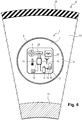
- the measuring device 1 comprises an electronic card 2 on which are welded a microcontroller 3 and an electromechanical pressure measurement microsystem, here a capacitive pressure sensor 20.
- the outer casing 6 comprises an orifice 21 for admitting fluid into the internal volume 7.
- the electronic card 2 is here mounted free, that is to say so as to be able to move there freely, in the internal volume 7.
- the card electronics 2 also receives an accelerometer 8, a Bluetooth transmitter / receiver 22 and a radio transmitter / receiver 10 which can be tuned to industrial, scientific and medical frequency bands and to GSM type network bands.
- the pressure measuring device 1 also comprises a thermocouple 23, a kinetic energy recuperator 12 comprising a converter 13 which converts the captured kinetic energy into electrical energy and sends it to a battery 14.
- the capacitive pressure sensor 20, the accelerometer 8, the Bluetooth transmitter / receiver 22, the radio transmitter / receiver 10, the temperature probe 11, the recuperator 12 and the battery 14 are integral with the electronic card 2 and connected to the microcontroller 3.
- the electronic card 2 also carries a SRAM memory module 15 connected to the microcontroller 3.
- the electronic board 2 and its components are embedded in a phenolic resin which, after hardening, forms a case 16 for protecting the electronic board 2.
- the pressure measuring device 1 When the pressure measuring device 1 is placed in a wheel 50 of an aircraft 100, the pressurized air which occupies the internal volume 53 of the wheel 50 enters the internal volume 7 of the pressure measuring device 1 through the orifice 21. The pressure which reigns in the internal volume 7 of the pressure measuring device 1 is then equal to the pressure which reigns in the internal volume 53 of the wheel 50. This pressure is measured by the capacitive pressure sensor 20 and is transmitted to the microcontroller 3.
- the operation of the pressure measuring device 1 according to the second embodiment of the invention is identical to that previously described.
- the Bluetooth transmitter / receiver 22 allows easy wireless communication of the value of the pressure of the wheel 50 to common mobile communication equipment of the smartphone type.
- the electronic card 2 can be integral with the outer casing 6, as in the first embodiment of the invention.
Landscapes
- Engineering & Computer Science (AREA)
- Mechanical Engineering (AREA)
- Computer Networks & Wireless Communication (AREA)
- Measuring Fluid Pressure (AREA)
- Arrangements For Transmission Of Measured Signals (AREA)
Description
La présente invention concerne la mesure de pression et plus particulièrement la mesure de pression dans une roue d'aéronef.The present invention relates to the measurement of pressure and more particularly to the measurement of pressure in an aircraft wheel.
Classiquement, une roue d'aéronef comprend une jante cylindrique portant un pneu définissant avec la jante un volume intérieur rempli d'un fluide sous pression, généralement de l'air. La mesure de la pression de l'air enfermé dans la roue est effectuée après chaque atterrissage à l'aide d'un dispositif de mesure de pression monté sur la valve de gonflage solidaire de la jante. La jante renferme généralement une pile de disque de freinage appelée puit de chaleur et qui dégage une importante quantité de chaleur lors du freinage de l'aéronef (températures supérieures à 500 degrés Celsius). Cette chaleur oblige à utiliser des matériaux et des techniques d'assemblage spécifiques qui rendent la fabrication d'un tel capteur de pression très couteux. De plus l'exposition du capteur à une température élevée lors de la mesure perturbe la précision de la mesure.Conventionally, an aircraft wheel comprises a cylindrical rim carrying a tire defining with the rim an interior volume filled with a pressurized fluid, generally air. The pressure of the air trapped in the wheel is measured after each landing using a pressure measuring device mounted on the inflation valve integral with the rim. The rim generally contains a stack of brake discs called a heat sink, which gives off a significant amount of heat when the aircraft is braked (temperatures above 500 degrees Celsius). This heat makes it necessary to use specific materials and assembly techniques which make the manufacture of such a pressure sensor very expensive. In addition, the exposure of the sensor to a high temperature during the measurement disturbs the precision of the measurement.
L'invention a pour objet d'améliorer la précision d'un dispositif de mesure de pression.The object of the invention is to improve the precision of a pressure measuring device.
A cet effet, on prévoit selon l'invention, une roue de véhicule comprenant une jante portant un pneu définissant avec la jante un volume intérieur rempli d'un fluide sous pression, la roue comprenant un dispositif de mesure de pression monté de manière à pouvoir se déplacer librement dans le volume intérieur. Le dispositif de mesure de pression comporte un circuit électronique de commande qui est relié à un capteur de pression, un capteur d'immobilité de la roue et à un circuit électronique de communication sans fil. Le dispositif de mesure de pression est agencé pour commander une mesure de pression lorsque la roue est détectée comme étant immobile.To this end, according to the invention, a vehicle wheel is provided comprising a rim carrying a tire defining with the rim an internal volume filled with a pressurized fluid, the wheel comprising a pressure measuring device mounted so as to be able to move freely in the interior space. The pressure measuring device comprises an electronic circuit for control which is connected to a pressure sensor, a wheel immobility sensor and to an electronic wireless communication circuit. The pressure measuring device is arranged to control a pressure measurement when the wheel is detected as being stationary.
On obtient alors un dispositif qui n'est pas soumis à la chaleur du puit de chaleur et qui réalise une mesure de pression en étant, de manière certaine, aussi éloigné que possible du puits de chaleur. Le capteur de pression du dispositif de mesure peut ainsi intégrer des composants dont la résistance à la chaleur est réduite par rapport à l'art antérieur et dont la précision est améliorée. Les températures auxquelles est exposé le dispositif de mesure lors de la mesure étant plus faibles, la compensation en température de la mesure peut être inexistante voire limitée, ce qui résulte en une meilleure précision de la mesure de pression réalisée par le dispositif selon l'invention.A device is then obtained which is not subjected to the heat of the heat sink and which performs a pressure measurement while being, with certainty, as far as possible from the heat sink. The pressure sensor of the measuring device can thus integrate components whose heat resistance is reduced compared to the prior art and whose precision is improved. The temperatures to which the measuring device is exposed during the measurement being lower, the temperature compensation of the measurement may be non-existent or even limited, which results in better precision of the pressure measurement carried out by the device according to the invention. .
La détection de l'immobilité de la roue est particulièrement efficace lorsque le capteur d'immobilité comprend un accéléromètre.The detection of the immobility of the wheel is particularly effective when the immobility sensor comprises an accelerometer.
Les couts de fabrication sont améliorés lorsque les moyens de communication sans fil comprennent un émetteur/récepteur Bluetooth et/ou une étiquette RFID et/ou un émetteur/récepteur radio accordé sur les bandes de fréquence industrielles, scientifiques et médicales.Manufacturing costs are improved when the means of wireless communication include a Bluetooth transmitter / receiver and / or an RFID tag and / or a radio transmitter / receiver tuned to the industrial, scientific and medical frequency bands.
Une compensation en température peut être réalisée et ainsi améliorer la précision de la mesure de pression lorsque le dispositif de mesure de pression comprend un capteur de température du fluide sous pression.Temperature compensation can be achieved and thus improve the precision of the pressure measurement when the pressure measurement device comprises a temperature sensor of the pressurized fluid.
L'autonomie du dispositif de mesure est grandement améliorée lorsque le dispositif de mesure de pression comprend des moyens de récupération d'énergie cinétique.The autonomy of the measuring device is greatly improved when the pressure measuring device comprises means for recovering kinetic energy.
Avantageusement, le dispositif de mesure de pression comprend une mémoire de stockage de données.Advantageously, the device for measuring pressure includes data storage memory.
La robustesse du dispositif de mesure est améliorée lorsque le dispositif comprend une enveloppe extérieure s'étendant autour d'un boîtier renfermant au moins une carte électronique.The robustness of the measuring device is improved when the device comprises an outer casing extending around a housing enclosing at least one electronic card.
Une fabrication économique est obtenue lorsque l'enveloppe extérieure est de forme sensiblement sphérique.Economical manufacture is obtained when the outer shell is substantially spherical in shape.
La mesure de pression en milieu hostile peut être effectuée lorsque l'enveloppe extérieure définit un volume intérieur hermétique et que le dispositif de mesure de pression comprend une jauge de déformation solidaire d'une surface intérieure de l'enveloppe extérieure et reliée à la carte électronique. Alternativement, l'enveloppe extérieure définit un volume intérieur et comprend au moins un orifice d'admission du fluide sous pression. Le dispositif de mesure de pression comprend alors un capteur de mesure de la pression dans le volume intérieur.Pressure measurement in a hostile environment can be performed when the outer casing defines an airtight inner volume and the pressure measuring device comprises a strain gauge secured to an inner surface of the outer casing and connected to the electronic card. . Alternatively, the outer casing defines an inner volume and comprises at least one pressurized fluid inlet port. The pressure measuring device then comprises a sensor for measuring the pressure in the interior volume.
L'invention porte également sur un dispositif de mesure de pression destiné à être placé dans une roue de véhicule selon l'invention.The invention also relates to a pressure measuring device intended to be placed in a vehicle wheel according to the invention.
L'invention porte également sur un procédé de mesure de pression d'une roue de véhicule à l'aide d'un dispositif de mesure selon l'invention, le procédé comprenant les étapes suivantes :
- a) détecter que le dispositif de mesure de pression est immobile depuis une durée prédéterminée ;
- b) mesurer la pression du volume intérieur;
- c) envoyer à l'aide du circuit électronique de communication sans fil une valeur de la pression mesurée.
- a) detecting that the pressure measuring device has been stationary for a predetermined period of time;
- b) measure the pressure of the interior volume;
- c) send a measured pressure value using the electronic wireless communication circuit.
Il sera fait référence aux figures annexées parmi lesquelles :
- la
figure 1 est une vue schématique en perspective d'une coupe d'un dispositif de mesure de pression selon un premier mode de réalisation de l'invention ; - la
figure 2 est une vue schématique en coupe d'une roue de véhicule selon un premier mode de réalisation de l'invention ; - les
figures 3 à 5 sont des vues schématiques en coupe de la roue de lafigure 2 dans diverses configurations dynamiques ; - la
figure 6 est une vue schématique partielle en coupe d'une roue selon un deuxième mode de réalisation de l'invention.
- the
figure 1 is a schematic perspective view of a section of a pressure measuring device according to a first embodiment of the invention; - the
figure 2 is a schematic sectional view of a vehicle wheel according to a first embodiment of the invention; - the
figures 3 to 5 are schematic sectional views of the wheel of thefigure 2 in various dynamic configurations; - the
figure 6 is a partial schematic sectional view of a wheel according to a second embodiment of the invention.
En référence à la
La carte électronique 2 reçoit également un accéléromètre 8, un étiquette RFID 9 et un émetteur/récepteur radio 10 pouvant s'accorder sur les bandes de fréquences industrielles, scientifiques et médicales et sur les bandes de réseau de type GSM. Les bandes de fréquences industrielles, scientifiques et médicales sont définies en Europe par la norme EN 55011 et la directive RED et permettent une communication longue distance à faible débit. Aux Etats-Unis, ces bandes sont définies par les parties 15 et 18 du titre 47 du "code of federal regulations". Ces bandes de fréquences sont généralement utilisées dans les applications dites « Internet des objets » ou IoT (pour « Internet Of Things » en anglais). Le dispositif de mesure de pression 1 comprend également une sonde de température 11 résistive, un récupérateur 12 d'énergie cinétique comprenant un convertisseur 13 qui convertit l'énergie cinétique captée en énergie électrique et l'envoie à une batterie 14. Le récupérateur d'énergie 12 comprend, ici, une bille 12.1 en matériau ferromagnétique pouvant se déplacer librement dans l'entrefer d'une bobine 12.2.The
L'accéléromètre 8, l'étiquette RFID 9, l'émetteur/récepteur radio 10, la sonde de température 11, le récupérateur 12 et la batterie 14 sont solidaires de la carte électronique 2 et reliés au microcontrôleur 3. La carte électronique 2 porte également un module de mémoire 15 SRAM relié au microcontrôleur 3.The
La carte électronique 2 ainsi que ses composants sont noyés dans une résine phénolique qui, après durcissement, réalise un boitier 16 de protection de la carte électronique 2, les points de vissage 2.1 étant laissés accessibles.The
Comme visible en
L'équipement avionique 101 de l'aéronef 100 comprend un émetteur/récepteur radio 102 accordé sur les fréquences d'émission/réception de l'émetteur/récepteur 10 du dispositif de mesure de pression 1.The
En fonctionnement, et en référence aux
Lors de la phase de vol, l'accéléromètre 8 détecte que la roue 50 est immobile. Le microcontrôleur 3 entame alors le décompte d'une durée T prédéterminée et stockée dans le module de mémoire 15, ici une durée de trente minutes. A l'issue de ce décompte, le microcontrôleur 3 lit la mesure de la jauge de contrainte 4 et de la sonde de température 11. Le microcontrôleur 3 transforme la déformation de l'enveloppe extérieure 6 soumise au différentiel de pression régnant entre le volume intérieur 7 du dispositif de pression 1 et le volume intérieur 53 de la roue 50 en une mesure de pression de l'air régnant dans le volume intérieur 53 à l'aide de la jauge de contrainte 4. Le microcontrôleur 3 réalise alors une compensation en température de la mesure de pression, en utilisant la mesure de la sonde de température 11 et en consultant une table de compensation de la dérive de la jauge de contrainte 4 en fonction de la température stockée dans le module de mémoire SRAM 15. Le microcontrôleur 3 envoie ensuite à l'aide de l'émetteur/récepteur radio 10 la valeur de la pression de la roue 50 à l'émetteur/récepteur radio 102 de l'aéronef 100. Le microcontrôleur 3 encode ensuite la valeur de la pression de la roue 50 au format adapté et l'enregistre dans l'étiquette RFID 9. Le microcontrôleur 3 commande ensuite la mise en veille du dispositif de mesure 1. Lors de cette mise en veille, l'énergie consommée par le dispositif est limitée à la seule surveillance de l'accéléromètre 8.During the flight phase, the
Avantageusement, l'accéléromètre 8 peut détecter le déplacement de l'aéronef 100 lors de sa phase de vol et ne pas effectuer la mesure de pression et la transmission de celle-ci. Lorsque la roue 50 est immobile, le dispositif de mesure de pression 1 est soumis à la gravité et repose au point le plus bas de la roue 50, c'est-à-dire à une distance d de la jante 51.Advantageously, the
Lors de l'atterrissage de l'aéronef 100, le dispositif de pression 1 est soumis à la rotation de la roue 50 et se déplace librement dans le volume intérieur 53 du pneu 52. Au cours de la rotation de la roue 50, l'accéléromètre 8 détecte le mouvement de la roue 50 et le récupérateur 12 convertit l'énergie cinétique à laquelle est soumis le dispositif de mesure de pression 1 en énergie électrique qui est stockée par la batterie 14.During the landing of the
Au cours de ces mouvements, le dispositif de mesure 1 est exceptionnellement en contact prolongé avec la jante 51.During these movements, the measuring
Une fois l'aéronef à l'arrêt l'accéléromètre 8 détecte que la roue 50 est immobile. Le microcontrôleur 3 entame alors le décompte d'une durée T prédéterminée et stockée dans le module de mémoire 15, ici une durée de trente minutes. A l'issue de ce décompte, le microcontrôleur 3 lit la mesure de la jauge de contrainte 4 et de la sonde de température 11. Le microcontrôleur 3 transforme la déformation de l'enveloppe extérieure 6 soumise au différentiel de pression régnant entre le volume intérieur 7 du dispositif de pression 1 et le volume intérieur 53 de la roue 50 en une mesure de pression de l'air régnant dans le volume intérieur 53 à l'aide de la jauge de contrainte 4. Le microcontrôleur 3 réalise alors une compensation en température de la mesure de pression, en utilisant la mesure de la sonde de température 11 et en consultant une table de compensation de la dérive de la jauge de contrainte 4 en fonction de la température stockée dans le module de mémoire SRAM 15. Le microcontrôleur 3 envoie ensuite à l'aide de l'émetteur/récepteur radio 10 la mesure de la pression de la roue 50 à l'émetteur/récepteur radio 102 de l'aéronef 100. Cette transmission de la mesure de la pression de la roue 50 peut également être adressée à un récepteur radio 202 d'une plateforme de maintenance 200 du lieu de parking de l'aéronef 100 -généralement un aéroport. Ceci permet d'éviter un déplacement des opérateurs de maintenance jusqu'à la roue 50 et assure un suivi automatisé de la roue 50. Une seconde transmission peut également avoir lieu via l'émetteur/récepteur 10 sur la bande de fréquence GSM, permettant à une plateforme distante d'effectuer un suivi de la roue 50. Le microcontrôleur 3 encode ensuite la valeur de la pression de la roue 50 au format adapté et l'enregistre dans l'étiquette RFID 9. Le microcontrôleur place alors le dispositif de mesure de pression 1 en veille.Once the aircraft has stopped, the
Lors de visite d'inspection de la roue 50, la pression peut être contrôlée à la demande à l'aide d'un interrogateur RFID 70. L'opérateur approche un interrogateur RFID 70 de la roue 50. Sous l'effet de l'interrogateur 70, l'étiquette RFID 9 envoie la valeur de la pression de la roue 50 qui est lue par l'interrogateur RFID 70.During an inspection visit to the
On obtient alors un dispositif de mesure de pression 1 qui réalise la mesure de pression en étant systématiquement éloigné le plus possible du puits de chaleur 54. Ceci permet de mettre en œuvre le capteur de pression 4 dans une plage de température dans laquelle l'influence de la température sur le capteur de pression 4 est limitée, voire aisément compensable. Les composants du dispositif de mesure de pression 1 subissent des températures moins élevées et peuvent donc être choisis dans des gammes moins couteuses que les composants de l'art antérieur. Les sollicitations mécaniques engendrées par la force centrifuge sur le dispositif de mesure de pression 1 sont également réduites et permettent, également, de retenir des composants plus économiques que ceux de l'art antérieur. Le dispositif de mesure 1 est ainsi plus économique et plus précis que les solutions existantes.A
Les éléments identiques ou analogues à ceux précédemment décrits porteront une référence numérique identique à ceux-ci dans la description qui suit d'un deuxième mode de réalisation de l'invention.Elements identical or similar to those previously described will bear a numerical reference identical to them in the following description of a second embodiment of the invention.
En référence à la
Le capteur de pression capacitif 20, l'accéléromètre 8, l'émetteur/récepteur Bluetooth 22, l'émetteur/récepteur radio 10, la sonde de température 11, le récupérateur 12 et la batterie 14 sont solidaires de la carte électronique 2 et reliés au microcontrôleur 3. La carte électronique 2 porte également un module de mémoire 15 SRAM relié au microcontrôleur 3.The
La carte électronique 2 ainsi que ses composants sont noyés dans une résine phénolique qui, après durcissement, réalise un boitier 16 de protection de la carte électronique 2.The
Lorsque le dispositif de mesure de pression 1 est placé dans une roue 50 d'un aéronef 100, l'air sous pression qui occupe le volume intérieur 53 de la roue 50 pénètre le volume intérieur 7 du dispositif de mesure de pression 1 par l'orifice 21. La pression qui règne dans le volume intérieur 7 du dispositif de mesure de pression 1 est alors égale à la pression qui règne dans le volume intérieur 53 de la roue 50. Cette pression est mesurée par le capteur de pression capacitif 20 et est transmise au microcontrôleur 3.When the
Le fonctionnement du dispositif de mesure de pression 1 selon le deuxième mode de réalisation de l'invention est identique à celui précédemment décrit. L'émetteur/récepteur Bluetooth 22 permet une communication sans fil aisée de la valeur de la pression de la roue 50 vers des équipements de communication mobile courants de type smartphone.
Bien entendu, la carte électronique 2 peut être solidaire de l'enveloppe extérieure 6, comme dans le premier mode de réalisation de l'invention.The operation of the
Of course, the
Bien entendu, l'invention n'est pas limitée aux modes de réalisation décrits mais englobe toute variante entrant dans le champ de l'invention tel que défini par les revendications.Of course, the invention is not limited to embodiments described but encompasses any variant coming within the scope of the invention as defined by the claims.
En particulier,
- bien qu'ici le dispositif de mesure de pression comprenne un microcontrôleur, l'invention s'applique également à d'autres types de circuit électronique de commande comme par exemple un FPGA, des portes logiques ou un microprocesseur ;
- bien qu'ici le microcontrôleur, ainsi que les autres composants, soient soudés sur une carte électronique, l'invention s'applique également à d'autres moyens de liaison des composants au circuit de commande comme par exemple des liaisons par brochage, par frittage ou par brasage sur un support de type PCB, ou des composants reliés de manière filaire;
- bien qu'ici la jauge de contrainte soit reliée par un fil au microcontrôleur, l'invention s'applique également à des liaisons sans fil entre les différents composants du dispositif de mesure de pression ;
- bien qu'ici le dispositif comprenne un nanosystème de mesure de pression ou un microsystème de mesure de pression, l'invention s'applique également à d'autres types de capteur de pression comme par exemple des capteurs résistifs, inductifs, capacitif ou à effet hall pouvant être nanométriques, micrométriques, millimétriques ou quelconques ;
- bien qu'ici la jauge de déformation soit collée sur la face intérieure de l'enveloppe extérieure du dispositif de mesure de pression, l'invention s'applique également à d'autres moyens de solidariser la jauge de pression à l'enveloppe extérieure comme par exemple une application de résine, une soudure ultrasonique ou un bouterollage ;
- bien qu'ici l'enveloppe extérieure soit de forme sensiblement sphérique, l'invention s'applique également à d'autres formes d'enveloppe extérieure comme par exemple une forme ovoïde, toute forme facilitant le roulement du dispositif dans le volume intérieur de la roue ou une forme quelconque. L'invention s'applique également à un dispositif de mesure de pression dépourvu d'enveloppe extérieure ;
- bien qu'ici l'enveloppe extérieure soit réalisée en caoutchouc synthétique, l'invention s'applique également à des enveloppes réalisées en d'autres matériaux comme par exemple du caoutchouc naturel, de l'EPDM, des polymères, des composites carbone/kevlar de l'acier inoxydable ou tout autre matériau ;
- bien qu'ici la carte électronique soit reliée à l'enveloppe extérieure par trois liens élastiques, l'invention s'applique également à une carte électronique reliée par un unique lien, deux liens ou plus de trois liens élastiques ou non, l'invention s'applique également à une carte électronique montée libre dans l'enveloppe extérieure ;
- bien qu'ici le dispositif de mesure comprenne un accéléromètre, l'invention s'applique également à d'autres types de capteur d'immobilité comme par exemple une centrale inertielle, un gyroscope, un ou plusieurs pendule, une ou plusieurs interrupteur actionné par la gravité ;
- bien qu'ici le dispositif de mesure de pression comprenne une étiquette RFID, l'invention s'applique également à d'autres types de technologies passives d'émission à courte distance comme par exemple un protocole NFC ;
- bien qu'ici le dispositif de mesure de pression comprenne un émetteur/récepteur Bluetooth, l'invention s'applique également à d'autres types de technologies actives d'émission à courte distance comme par exemple les technologies Wi-Fi, ou ultra-son ;
- bien qu'ici le dispositif de mesure de pression comprenne une énetteur/récepteur radio pouvant s'accorder sur les bandes de types GSM, l'invention s'applique également à d'autres types de techniques d'émission à sur un réseau public comme par exemple un protocole 2G, 3G, 4G, 5G, de type LoRa, edge ou dérivées du standard IEEE 802.15.4;
- bien qu'ici le dispositif de mesure de pression comprenne une sonde de température résistive, l'invention s'applique également à d'autres types de capteurs de température du fluide sous pression régnant dans la roue comme par exemple un thermocouple ou un pyromètre infrarouge;
- bien qu'ici le dispositif de mesure de pression comprenne un convertisseur d'énergie cinétique inductif, l'invention s'applique également à d'autres types de convertisseurs d'énergie comme par exemple un convertisseur d'énergie cinétique de type piézoélectrique ou un convertisseur d'énergie thermique ;
- bien qu'ici le dispositif de mesure de pression comprenne une mémoire SRAM, l'invention s'applique également à d'autres types de mémoire de stockage de données comme par exemple une mémoire DPRAM, MAM, PRAM, un disque dur ou une
- although here the pressure measuring device comprises a microcontroller, the invention also applies to other types of electronic control circuit such as for example an FPGA, logic gates or a microprocessor;
- although here the microcontroller, as well as the other components, are soldered on an electronic card, the invention also applies to other means of connection of the components to the control circuit such as for example connections by pinning, by sintering or by soldering on a PCB type support, or components connected by wire;
- although here the strain gauge is connected by a wire to the microcontroller, the invention also applies to wireless connections between the various components of the pressure measuring device;
- although here the device comprises a nanosystem for measuring pressure or a microsystem for measuring pressure, the invention also applies to other types of pressure sensor such as, for example, resistive, inductive, capacitive or effect sensors hall which can be nanometric, micrometric, millimeter or any;
- although here the deformation gauge is glued to the inner face of the outer casing of the pressure measuring device, the invention also applies to other means of securing the pressure gauge to the casing exterior, for example resin application, ultrasonic welding or snap-gluing;
- although here the outer casing is of substantially spherical shape, the invention also applies to other shapes of outer casing such as for example an ovoid shape, any shape facilitating the rolling of the device in the internal volume of the wheel or any shape. The invention also applies to a pressure measuring device without an outer casing;
- although here the outer casing is made of synthetic rubber, the invention also applies to casings made of other materials such as for example natural rubber, EPDM, polymers, carbon / Kevlar composites stainless steel or any other material;
- although here the electronic card is connected to the outer casing by three elastic links, the invention also applies to an electronic card connected by a single link, two links or more than three elastic links or not, the invention also applies to an electronic card mounted freely in the outer casing;
- although here the measuring device comprises an accelerometer, the invention also applies to other types of immobility sensor such as for example an inertial unit, a gyroscope, one or more pendulum, one or more switches actuated by gravity ;
- although here the pressure measuring device comprises an RFID tag, the invention also applies to other types of passive transmission technologies at short distances such as for example an NFC protocol;
- although here the pressure measuring device comprises a Bluetooth transmitter / receiver, the invention also applies to other types of active short-range transmission technologies such as, for example, Wi-Fi, or ultra-high technology. his ;
- although here the pressure measuring device comprises a radio transmitter / receiver which can be tuned to GSM-type bands, the invention also applies to other types of transmission techniques on a public network such as for example a 2G, 3G, 4G, 5G protocol, of the LoRa or edge type or derived from the IEEE 802.15.4 standard;
- although here the pressure measuring device comprises a resistive temperature probe, the invention also applies to other types of temperature sensors of the pressurized fluid prevailing in the wheel such as for example a thermocouple or an infrared pyrometer ;
- although here the pressure measuring device comprises an inductive kinetic energy converter, the invention also applies to other types of energy converters such as for example a kinetic energy converter of the piezoelectric type or a thermal energy converter;
- although here the pressure measuring device comprises an SRAM memory, the invention also applies to other types of data storage memory such as for example a DPRAM, MAM, PRAM memory, a hard disk or a
Claims (12)
- A vehicle wheel (50) for a vehicle (100), the wheel comprising a rim (51) carrying a tire (52) co-operating with the rim (51) to define an inside volume (53) that is filled with a fluid under pressure, the wheel (50) including a pressure measurement device (1) mounted so as to be capable of moving freely in the inside volume (53), the pressure measurement device (1) comprising an electronic control circuit (3) that is connected to a pressure sensor (4, 20), to an absence-of-movement sensor (8) for sensing when the wheel (50) is not moving, and to an electronic circuit (9, 10, 22) for wireless communication, the pressure measurement device (1) being arranged to cause pressure to be measured while the wheel (50) is detected as not moving.
- A vehicle wheel (50) according to claim 1, wherein the absence-of-movement sensor comprises an accelerometer (8) .
- A vehicle wheel (50) according to any preceding claim, wherein the electronic circuit for wireless communication comprises a Bluetooth transceiver (22) and/or an RFID tag (9) and/or a radio transceiver (10) tuned to the industrial, scientific, and medical frequency bands.
- A vehicle wheel (50) according to any preceding claim, wherein the pressure measurement device (1) includes a temperature sensor (11) for sensing the temperature of the fluid under pressure.
- A vehicle wheel (50) according to any preceding claim, wherein the pressure measurement device (1) includes means (12) for recovering kinetic energy.
- A vehicle wheel (50) according to any preceding claim, wherein the pressure measurement device (1) includes a data storage memory (15).
- A vehicle wheel (50) according to any preceding claim, wherein the pressure measurement device (1) includes an outer shell (6) extending around a housing (16) containing at least one electronic card (2).
- A vehicle wheel (50) according to claim 7, wherein the outer shell (6) is substantially spherical in shape.
- A vehicle wheel (50) according to claim 7 or claim 8, wherein the outer shell (6) defines a hermetically sealed inside volume (7), the pressure measurement device (1) including a strain gauge (4) secured to an inside surface (5) of the outer shell (6) and connected to the electronic card (2).
- A vehicle wheel (50) according to claim 7 or claim 8, wherein the outer shell (6) defines an inside volume (7) and includes at least one orifice (21) for admitting the fluid under pressure, the pressure measurement device (1) including a pressure measurement sensor (20) in the inside volume.
- A pressure measurement device (1) for placing in a vehicle wheel (50) according to any one of claims 1 to 10.
- A method of measuring pressure in a vehicle wheel (50) using a measurement device according to any one of claims 1 to 10, the method comprising the following steps:a) detecting that the pressure measurement device (1) has not been moving for a predetermined duration;b) measuring the pressure of the inside volume (53); andc) using the electronic circuit (9, 10, 22) for wireless communication to send a measured pressure value.
Applications Claiming Priority (2)
| Application Number | Priority Date | Filing Date | Title |
|---|---|---|---|
| FR1761238A FR3074096B1 (en) | 2017-11-27 | 2017-11-27 | AUTONOMOUS ON-BOARD PRESSURE MEASUREMENT DEVICE PRESSURE MEASUREMENT METHOD |
| PCT/EP2018/081131 WO2019101583A1 (en) | 2017-11-27 | 2018-11-13 | Standalone on-board pressure measurement device, and pressure measurement method |
Publications (2)
| Publication Number | Publication Date |
|---|---|
| EP3717285A1 EP3717285A1 (en) | 2020-10-07 |
| EP3717285B1 true EP3717285B1 (en) | 2021-12-29 |
Family
ID=62222730
Family Applications (1)
| Application Number | Title | Priority Date | Filing Date |
|---|---|---|---|
| EP18803418.5A Active EP3717285B1 (en) | 2017-11-27 | 2018-11-13 | Embedded system for measuring pressure and method |
Country Status (5)
| Country | Link |
|---|---|
| US (1) | US10953709B2 (en) |
| EP (1) | EP3717285B1 (en) |
| CN (1) | CN111405993B (en) |
| FR (1) | FR3074096B1 (en) |
| WO (1) | WO2019101583A1 (en) |
Families Citing this family (5)
| Publication number | Priority date | Publication date | Assignee | Title |
|---|---|---|---|---|
| GB2602012A (en) * | 2020-12-15 | 2022-06-22 | Airbus Operations Ltd | Tyre monitor |
| GB2602260A (en) * | 2020-12-16 | 2022-06-29 | Airbus Operations Ltd | Wheel assembly sensor apparatus |
| GB202019750D0 (en) * | 2020-12-15 | 2021-01-27 | Airbus Operations Ltd | Tyre monitor |
| US20240083200A1 (en) * | 2020-12-15 | 2024-03-14 | Airbus Operations Limited | Tyre monitor |
| GB2623795A (en) * | 2022-10-27 | 2024-05-01 | Airbus Operations Ltd | A tire monitoring device |
Family Cites Families (10)
| Publication number | Priority date | Publication date | Assignee | Title |
|---|---|---|---|---|
| US6278363B1 (en) * | 2000-07-14 | 2001-08-21 | Motorola, Inc | Method and system for monitoring air pressure of tires on a vehicle |
| AU2011247846B2 (en) * | 2003-02-04 | 2012-06-07 | Bridgestone Americas Tire Operations, Llc | Non-attached tire monitoring device |
| CN101492000B (en) * | 2008-01-22 | 2010-12-08 | 苏州驶安特汽车电子有限公司 | Tire pressure real-time monitoring method using tire pressure monitoring system |
| US8742912B2 (en) * | 2008-12-31 | 2014-06-03 | Stmicroelectronics, Inc. | Self-powered sensor system for monitoring tire pressure |
| DE102010003954A1 (en) * | 2010-04-14 | 2011-10-20 | Robert Bosch Gmbh | Method and device for monitoring the tire pressure of motor vehicle tires |
| US8723661B2 (en) * | 2011-10-31 | 2014-05-13 | Hong Kong Applied Science and Technology Research Institute Company Limited | Mount-free tire pressure monitoring system |
| US9016117B2 (en) * | 2012-05-23 | 2015-04-28 | Yuval Solomon | Tire monitoring apparatus, system and method of using the same |
| FI125958B (en) * | 2013-05-10 | 2016-04-29 | Murata Manufacturing Co | Improved pressure sensor |
| GB2540414A (en) * | 2015-07-16 | 2017-01-18 | Airbus Operations Ltd | Tyre pressure sensor device |
| CN205239028U (en) * | 2015-11-25 | 2016-05-18 | 领联汽车零部件制造(上海)有限公司 | Electromagnetic induction type tire pressure sensor |
-
2017
- 2017-11-27 FR FR1761238A patent/FR3074096B1/en not_active Expired - Fee Related
-
2018
- 2018-11-13 US US16/763,316 patent/US10953709B2/en active Active
- 2018-11-13 EP EP18803418.5A patent/EP3717285B1/en active Active
- 2018-11-13 CN CN201880076471.7A patent/CN111405993B/en active Active
- 2018-11-13 WO PCT/EP2018/081131 patent/WO2019101583A1/en unknown
Also Published As
| Publication number | Publication date |
|---|---|
| US10953709B2 (en) | 2021-03-23 |
| CN111405993A (en) | 2020-07-10 |
| EP3717285A1 (en) | 2020-10-07 |
| WO2019101583A1 (en) | 2019-05-31 |
| CN111405993B (en) | 2022-05-27 |
| US20200290411A1 (en) | 2020-09-17 |
| FR3074096A1 (en) | 2019-05-31 |
| FR3074096B1 (en) | 2019-12-20 |
Similar Documents
| Publication | Publication Date | Title |
|---|---|---|
| EP3717285B1 (en) | Embedded system for measuring pressure and method | |
| US11814189B2 (en) | Internal tire and/or wheel monitoring device and method | |
| EP3394837B1 (en) | Aircraft landing gear ageing monitoring method | |
| CA2775382C (en) | Sealed pressure-measuring member | |
| EP2956686B1 (en) | Instrumented damper and performance monitoring system comprising such a damper | |
| EP3304022B1 (en) | Pressure-measuring device with improved reliability and associated calibration method | |
| US20130312509A1 (en) | Tire monitoring apparatus, system and method of using the same | |
| CN113167674B (en) | Closed pressure sensor | |
| WO2016096667A1 (en) | System for evaluating the condition of a tyre | |
| EP2642149A1 (en) | System for measuring the temperature of braking parts of motor vehicles | |
| WO2021191154A1 (en) | Device for measuring tyre pressure | |
| FR3108402A1 (en) | Device for measuring an operating parameter of a tire | |
| US10102688B2 (en) | Wireless data system for measuring relative motion of transmission components | |
| EP2703798A1 (en) | Equipment for measuring the inflation pressure of a tire of a vehicle wheel | |
| FR2504675A1 (en) | Contactless monitor for vehicle tyre pressure - utilises pressure sensor at wheel hub connected through transformer with axle as core to galvanometric indicator | |
| FR3125570A1 (en) | Hydromechanical braking indicator device | |
| CA3233188A1 (en) | Method and system for determining the pressure of an aircraft tyre | |
| WO2024213485A1 (en) | Landing gear with a device for measuring rotational speed |
Legal Events
| Date | Code | Title | Description |
|---|---|---|---|
| STAA | Information on the status of an ep patent application or granted ep patent |
Free format text: STATUS: UNKNOWN |
|
| STAA | Information on the status of an ep patent application or granted ep patent |
Free format text: STATUS: THE INTERNATIONAL PUBLICATION HAS BEEN MADE |
|
| PUAI | Public reference made under article 153(3) epc to a published international application that has entered the european phase |
Free format text: ORIGINAL CODE: 0009012 |
|
| STAA | Information on the status of an ep patent application or granted ep patent |
Free format text: STATUS: REQUEST FOR EXAMINATION WAS MADE |
|
| 17P | Request for examination filed |
Effective date: 20200611 |
|
| AK | Designated contracting states |
Kind code of ref document: A1 Designated state(s): AL AT BE BG CH CY CZ DE DK EE ES FI FR GB GR HR HU IE IS IT LI LT LU LV MC MK MT NL NO PL PT RO RS SE SI SK SM TR |
|
| AX | Request for extension of the european patent |
Extension state: BA ME |
|
| DAV | Request for validation of the european patent (deleted) | ||
| DAX | Request for extension of the european patent (deleted) | ||
| GRAP | Despatch of communication of intention to grant a patent |
Free format text: ORIGINAL CODE: EPIDOSNIGR1 |
|
| STAA | Information on the status of an ep patent application or granted ep patent |
Free format text: STATUS: GRANT OF PATENT IS INTENDED |
|
| INTG | Intention to grant announced |
Effective date: 20210630 |
|
| GRAS | Grant fee paid |
Free format text: ORIGINAL CODE: EPIDOSNIGR3 |
|
| RAP3 | Party data changed (applicant data changed or rights of an application transferred) |
Owner name: SAFRAN ELECTRONICS & DEFENSE |
|
| RIN1 | Information on inventor provided before grant (corrected) |
Inventor name: COUTURIER, EMMANUEL Inventor name: FANTON, NICOLAS Inventor name: BICKARD, THIERRY |
|
| GRAA | (expected) grant |
Free format text: ORIGINAL CODE: 0009210 |
|
| STAA | Information on the status of an ep patent application or granted ep patent |
Free format text: STATUS: THE PATENT HAS BEEN GRANTED |
|
| AK | Designated contracting states |
Kind code of ref document: B1 Designated state(s): AL AT BE BG CH CY CZ DE DK EE ES FI FR GB GR HR HU IE IS IT LI LT LU LV MC MK MT NL NO PL PT RO RS SE SI SK SM TR |
|
| REG | Reference to a national code |
Ref country code: GB Ref legal event code: FG4D Free format text: NOT ENGLISH |
|
| REG | Reference to a national code |
Ref country code: CH Ref legal event code: EP |
|
| REG | Reference to a national code |
Ref country code: AT Ref legal event code: REF Ref document number: 1458415 Country of ref document: AT Kind code of ref document: T Effective date: 20220115 |
|
| REG | Reference to a national code |
Ref country code: IE Ref legal event code: FG4D Free format text: LANGUAGE OF EP DOCUMENT: FRENCH |
|
| REG | Reference to a national code |
Ref country code: DE Ref legal event code: R096 Ref document number: 602018028900 Country of ref document: DE |
|
| REG | Reference to a national code |
Ref country code: LT Ref legal event code: MG9D |
|
| PG25 | Lapsed in a contracting state [announced via postgrant information from national office to epo] |
Ref country code: RS Free format text: LAPSE BECAUSE OF FAILURE TO SUBMIT A TRANSLATION OF THE DESCRIPTION OR TO PAY THE FEE WITHIN THE PRESCRIBED TIME-LIMIT Effective date: 20211229 Ref country code: LT Free format text: LAPSE BECAUSE OF FAILURE TO SUBMIT A TRANSLATION OF THE DESCRIPTION OR TO PAY THE FEE WITHIN THE PRESCRIBED TIME-LIMIT Effective date: 20211229 Ref country code: FI Free format text: LAPSE BECAUSE OF FAILURE TO SUBMIT A TRANSLATION OF THE DESCRIPTION OR TO PAY THE FEE WITHIN THE PRESCRIBED TIME-LIMIT Effective date: 20211229 Ref country code: BG Free format text: LAPSE BECAUSE OF FAILURE TO SUBMIT A TRANSLATION OF THE DESCRIPTION OR TO PAY THE FEE WITHIN THE PRESCRIBED TIME-LIMIT Effective date: 20220329 |
|
| REG | Reference to a national code |
Ref country code: NL Ref legal event code: MP Effective date: 20211229 |
|
| REG | Reference to a national code |
Ref country code: AT Ref legal event code: MK05 Ref document number: 1458415 Country of ref document: AT Kind code of ref document: T Effective date: 20211229 |
|
| PG25 | Lapsed in a contracting state [announced via postgrant information from national office to epo] |
Ref country code: SE Free format text: LAPSE BECAUSE OF FAILURE TO SUBMIT A TRANSLATION OF THE DESCRIPTION OR TO PAY THE FEE WITHIN THE PRESCRIBED TIME-LIMIT Effective date: 20211229 Ref country code: NO Free format text: LAPSE BECAUSE OF FAILURE TO SUBMIT A TRANSLATION OF THE DESCRIPTION OR TO PAY THE FEE WITHIN THE PRESCRIBED TIME-LIMIT Effective date: 20220329 Ref country code: LV Free format text: LAPSE BECAUSE OF FAILURE TO SUBMIT A TRANSLATION OF THE DESCRIPTION OR TO PAY THE FEE WITHIN THE PRESCRIBED TIME-LIMIT Effective date: 20211229 Ref country code: HR Free format text: LAPSE BECAUSE OF FAILURE TO SUBMIT A TRANSLATION OF THE DESCRIPTION OR TO PAY THE FEE WITHIN THE PRESCRIBED TIME-LIMIT Effective date: 20211229 Ref country code: GR Free format text: LAPSE BECAUSE OF FAILURE TO SUBMIT A TRANSLATION OF THE DESCRIPTION OR TO PAY THE FEE WITHIN THE PRESCRIBED TIME-LIMIT Effective date: 20220330 |
|
| PG25 | Lapsed in a contracting state [announced via postgrant information from national office to epo] |
Ref country code: NL Free format text: LAPSE BECAUSE OF FAILURE TO SUBMIT A TRANSLATION OF THE DESCRIPTION OR TO PAY THE FEE WITHIN THE PRESCRIBED TIME-LIMIT Effective date: 20211229 |
|
| PG25 | Lapsed in a contracting state [announced via postgrant information from national office to epo] |
Ref country code: SM Free format text: LAPSE BECAUSE OF FAILURE TO SUBMIT A TRANSLATION OF THE DESCRIPTION OR TO PAY THE FEE WITHIN THE PRESCRIBED TIME-LIMIT Effective date: 20211229 Ref country code: SK Free format text: LAPSE BECAUSE OF FAILURE TO SUBMIT A TRANSLATION OF THE DESCRIPTION OR TO PAY THE FEE WITHIN THE PRESCRIBED TIME-LIMIT Effective date: 20211229 Ref country code: RO Free format text: LAPSE BECAUSE OF FAILURE TO SUBMIT A TRANSLATION OF THE DESCRIPTION OR TO PAY THE FEE WITHIN THE PRESCRIBED TIME-LIMIT Effective date: 20211229 Ref country code: PT Free format text: LAPSE BECAUSE OF FAILURE TO SUBMIT A TRANSLATION OF THE DESCRIPTION OR TO PAY THE FEE WITHIN THE PRESCRIBED TIME-LIMIT Effective date: 20220429 Ref country code: ES Free format text: LAPSE BECAUSE OF FAILURE TO SUBMIT A TRANSLATION OF THE DESCRIPTION OR TO PAY THE FEE WITHIN THE PRESCRIBED TIME-LIMIT Effective date: 20211229 Ref country code: EE Free format text: LAPSE BECAUSE OF FAILURE TO SUBMIT A TRANSLATION OF THE DESCRIPTION OR TO PAY THE FEE WITHIN THE PRESCRIBED TIME-LIMIT Effective date: 20211229 Ref country code: CZ Free format text: LAPSE BECAUSE OF FAILURE TO SUBMIT A TRANSLATION OF THE DESCRIPTION OR TO PAY THE FEE WITHIN THE PRESCRIBED TIME-LIMIT Effective date: 20211229 |
|
| PG25 | Lapsed in a contracting state [announced via postgrant information from national office to epo] |
Ref country code: PL Free format text: LAPSE BECAUSE OF FAILURE TO SUBMIT A TRANSLATION OF THE DESCRIPTION OR TO PAY THE FEE WITHIN THE PRESCRIBED TIME-LIMIT Effective date: 20211229 Ref country code: AT Free format text: LAPSE BECAUSE OF FAILURE TO SUBMIT A TRANSLATION OF THE DESCRIPTION OR TO PAY THE FEE WITHIN THE PRESCRIBED TIME-LIMIT Effective date: 20211229 |
|
| PG25 | Lapsed in a contracting state [announced via postgrant information from national office to epo] |
Ref country code: IS Free format text: LAPSE BECAUSE OF FAILURE TO SUBMIT A TRANSLATION OF THE DESCRIPTION OR TO PAY THE FEE WITHIN THE PRESCRIBED TIME-LIMIT Effective date: 20220429 |
|
| REG | Reference to a national code |
Ref country code: DE Ref legal event code: R097 Ref document number: 602018028900 Country of ref document: DE |
|
| PG25 | Lapsed in a contracting state [announced via postgrant information from national office to epo] |
Ref country code: DK Free format text: LAPSE BECAUSE OF FAILURE TO SUBMIT A TRANSLATION OF THE DESCRIPTION OR TO PAY THE FEE WITHIN THE PRESCRIBED TIME-LIMIT Effective date: 20211229 Ref country code: AL Free format text: LAPSE BECAUSE OF FAILURE TO SUBMIT A TRANSLATION OF THE DESCRIPTION OR TO PAY THE FEE WITHIN THE PRESCRIBED TIME-LIMIT Effective date: 20211229 |
|
| PLBE | No opposition filed within time limit |
Free format text: ORIGINAL CODE: 0009261 |
|
| STAA | Information on the status of an ep patent application or granted ep patent |
Free format text: STATUS: NO OPPOSITION FILED WITHIN TIME LIMIT |
|
| 26N | No opposition filed |
Effective date: 20220930 |
|
| PG25 | Lapsed in a contracting state [announced via postgrant information from national office to epo] |
Ref country code: SI Free format text: LAPSE BECAUSE OF FAILURE TO SUBMIT A TRANSLATION OF THE DESCRIPTION OR TO PAY THE FEE WITHIN THE PRESCRIBED TIME-LIMIT Effective date: 20211229 |
|
| PG25 | Lapsed in a contracting state [announced via postgrant information from national office to epo] |
Ref country code: IT Free format text: LAPSE BECAUSE OF FAILURE TO SUBMIT A TRANSLATION OF THE DESCRIPTION OR TO PAY THE FEE WITHIN THE PRESCRIBED TIME-LIMIT Effective date: 20211229 |
|
| REG | Reference to a national code |
Ref country code: DE Ref legal event code: R119 Ref document number: 602018028900 Country of ref document: DE |
|
| PG25 | Lapsed in a contracting state [announced via postgrant information from national office to epo] |
Ref country code: MC Free format text: LAPSE BECAUSE OF FAILURE TO SUBMIT A TRANSLATION OF THE DESCRIPTION OR TO PAY THE FEE WITHIN THE PRESCRIBED TIME-LIMIT Effective date: 20211229 |
|
| REG | Reference to a national code |
Ref country code: CH Ref legal event code: PL |
|
| GBPC | Gb: european patent ceased through non-payment of renewal fee |
Effective date: 20221113 |
|
| REG | Reference to a national code |
Ref country code: BE Ref legal event code: MM Effective date: 20221130 |
|
| PG25 | Lapsed in a contracting state [announced via postgrant information from national office to epo] |
Ref country code: LI Free format text: LAPSE BECAUSE OF NON-PAYMENT OF DUE FEES Effective date: 20221130 Ref country code: CH Free format text: LAPSE BECAUSE OF NON-PAYMENT OF DUE FEES Effective date: 20221130 |
|
| PG25 | Lapsed in a contracting state [announced via postgrant information from national office to epo] |
Ref country code: LU Free format text: LAPSE BECAUSE OF NON-PAYMENT OF DUE FEES Effective date: 20221113 |
|
| PG25 | Lapsed in a contracting state [announced via postgrant information from national office to epo] |
Ref country code: IE Free format text: LAPSE BECAUSE OF NON-PAYMENT OF DUE FEES Effective date: 20221113 Ref country code: GB Free format text: LAPSE BECAUSE OF NON-PAYMENT OF DUE FEES Effective date: 20221113 Ref country code: DE Free format text: LAPSE BECAUSE OF NON-PAYMENT OF DUE FEES Effective date: 20230601 |
|
| PG25 | Lapsed in a contracting state [announced via postgrant information from national office to epo] |
Ref country code: BE Free format text: LAPSE BECAUSE OF NON-PAYMENT OF DUE FEES Effective date: 20221130 |
|
| PGFP | Annual fee paid to national office [announced via postgrant information from national office to epo] |
Ref country code: FR Payment date: 20231020 Year of fee payment: 6 |
|
| PG25 | Lapsed in a contracting state [announced via postgrant information from national office to epo] |
Ref country code: CY Free format text: LAPSE BECAUSE OF FAILURE TO SUBMIT A TRANSLATION OF THE DESCRIPTION OR TO PAY THE FEE WITHIN THE PRESCRIBED TIME-LIMIT Effective date: 20211229 |
|
| PG25 | Lapsed in a contracting state [announced via postgrant information from national office to epo] |
Ref country code: MK Free format text: LAPSE BECAUSE OF FAILURE TO SUBMIT A TRANSLATION OF THE DESCRIPTION OR TO PAY THE FEE WITHIN THE PRESCRIBED TIME-LIMIT Effective date: 20211229 Ref country code: HU Free format text: LAPSE BECAUSE OF FAILURE TO SUBMIT A TRANSLATION OF THE DESCRIPTION OR TO PAY THE FEE WITHIN THE PRESCRIBED TIME-LIMIT; INVALID AB INITIO Effective date: 20181113 |
|
| PG25 | Lapsed in a contracting state [announced via postgrant information from national office to epo] |
Ref country code: MT Free format text: LAPSE BECAUSE OF FAILURE TO SUBMIT A TRANSLATION OF THE DESCRIPTION OR TO PAY THE FEE WITHIN THE PRESCRIBED TIME-LIMIT Effective date: 20211229 |