EP3716738A1 - Insertion device - Google Patents
Insertion device Download PDFInfo
- Publication number
- EP3716738A1 EP3716738A1 EP20165160.1A EP20165160A EP3716738A1 EP 3716738 A1 EP3716738 A1 EP 3716738A1 EP 20165160 A EP20165160 A EP 20165160A EP 3716738 A1 EP3716738 A1 EP 3716738A1
- Authority
- EP
- European Patent Office
- Prior art keywords
- coupling
- magnet
- spring
- pair
- supporting member
- Prior art date
- Legal status (The legal status is an assumption and is not a legal conclusion. Google has not performed a legal analysis and makes no representation as to the accuracy of the status listed.)
- Granted
Links
Images







Classifications
-
- H—ELECTRICITY
- H05—ELECTRIC TECHNIQUES NOT OTHERWISE PROVIDED FOR
- H05H—PLASMA TECHNIQUE; PRODUCTION OF ACCELERATED ELECTRICALLY-CHARGED PARTICLES OR OF NEUTRONS; PRODUCTION OR ACCELERATION OF NEUTRAL MOLECULAR OR ATOMIC BEAMS
- H05H7/00—Details of devices of the types covered by groups H05H9/00, H05H11/00, H05H13/00
- H05H7/04—Magnet systems, e.g. undulators, wigglers; Energisation thereof
-
- H—ELECTRICITY
- H01—ELECTRIC ELEMENTS
- H01F—MAGNETS; INDUCTANCES; TRANSFORMERS; SELECTION OF MATERIALS FOR THEIR MAGNETIC PROPERTIES
- H01F7/00—Magnets
- H01F7/02—Permanent magnets [PM]
- H01F7/0205—Magnetic circuits with PM in general
- H01F7/0221—Mounting means for PM, supporting, coating, encapsulating PM
-
- H—ELECTRICITY
- H05—ELECTRIC TECHNIQUES NOT OTHERWISE PROVIDED FOR
- H05H—PLASMA TECHNIQUE; PRODUCTION OF ACCELERATED ELECTRICALLY-CHARGED PARTICLES OR OF NEUTRONS; PRODUCTION OR ACCELERATION OF NEUTRAL MOLECULAR OR ATOMIC BEAMS
- H05H7/00—Details of devices of the types covered by groups H05H9/00, H05H11/00, H05H13/00
- H05H7/04—Magnet systems, e.g. undulators, wigglers; Energisation thereof
- H05H2007/041—Magnet systems, e.g. undulators, wigglers; Energisation thereof for beam bunching, e.g. undulators
Definitions
- the present invention relates to insertion devices including a first magnet array constituted by a plurality of magnets placed in an array, a first magnet supporting member for supporting the first magnet array mounted thereto, a second magnet array which is constituted by a plurality of magnets placed in an array and facing the first magnet array with a gap interposed therebetween, a second magnet supporting member for supporting the second magnet array mounted thereto, a gap driving mechanism for driving the first magnet supporting member and/or the second magnet supporting member in the direction in which the magnet arrays are facing each other, in order to change the size of the gap, and a driving conjunction mechanism for coupling the gap driving mechanism and the magnet supporting members to each other.
- synchrotron radiation If an electron beam having been accelerated to near the light velocity in a vacuum is bent within a magnet field, radiated light is emitted in tangential directions of the trajectory of the movement of the electron beam. This is called synchrotron radiation.
- electron-beam accumulating rings There have been made studies for practical applications of various techniques for installing light sources for generating such synchrotron radiation in straight sections of electron storage rings (electron-beam accumulating rings), in order to utilize their properties such as high directivity, high intensity, and high polarization properties.
- Existing electron storage rings have been provided with plural insertion devices (undulators), as high-brightness light sources with higher beam electric currents and smaller beam cross-sectional areas.
- Non-Patent Document 1 As such insertion devices, there has been known an insertion device disclosed in the following Non-Patent Document 1, for example.
- This insertion device has a structure including a first magnet array constituted by a plurality of magnets placed in an array, and a second magnet array constituted by a plurality of magnets placed in an array, which are facing each other with a gap interposed therebetween. Since the arrays of the plural magnets are facing each other, large attractive forces are exerted between both of them.
- Patent Document 1 discloses a structure provided with a compensation spring mechanism, in order to overcome the aforementioned problem.
- the magnet supporting members mentioned above are coupled to coupling beams via mechanisms (coupling shafts) that are vertical to the coupling beams, and the size of the gap is changed by moving the coupling beams in the vertical direction.
- the compensation spring mechanism is also coupled to the coupling beams via coupling portions.
- the coupling portions of the compensation spring mechanisms are placed between a plurality of coupling shafts. This is because they physically interfere with each other. Therefore, the positions of the coupling shafts once determined, inevitably and substantially determine the positions of the coupling portions and the compensation spring mechanisms.
- Patent Document 1 WO2018/143253 A1
- Non-Patent Document 1 Winick, Herman; George Brown; Klaus Halbach; John Harris (May 1981). "Synchrotron Radiation Wiggler and Undulator Magnets" Physics Today, May 1981, Volume 34, Issue 5, pp. 50 - 63
- the inventors of the present invention have found out that optimal positions of the compensation spring mechanisms relative to the positions of the coupling shafts in the insertion device having the configuration described above could be determined by simulation. Namely, it has been found out that there have been optimal positions for the compensation spring mechanisms where deformation of coupling beams could be most suppressed, depending on the length of the coupling beams, mounting positions of the coupling shafts, the number of compensation spring mechanisms to be placed, and so on.
- the present invention has been made in view of the circumstances described above, and it is an object of the present invention to provide an insertion device that can minimize deformation of coupling beams through optimization of the position of the compensation spring mechanism.
- an insertion device includes:
- the first magnet supporting member is integrally coupled to the first coupling beam
- the second magnet supporting member is integrally coupled to the second coupling beam.
- the gap driving mechanism drives at least one of the first coupling beam and the second coupling beam for changing the size of the gap.
- the spring conjunction mechanism includes the first spring supporting frame and the second spring supporting frame, which are mounted to the first auxiliary frame and the second auxiliary frame, respectively.
- first auxiliary frame and second auxiliary frame are coupled to the first coupling beam and the second coupling beam via the pairs of first coupling portions and second coupling portions, respectively. Further, the first spring supporting frame and the second spring supporting frame are allowed to move relative to each other, through the guide mechanism, in the direction in which the magnet arrays are facing each other.
- first auxiliary frame and second auxiliary frame are formed to make a space available for placing a mechanism for coupling the magnet supporting member and the coupling beam to each other.
- the compensation spring mechanism can thus be placed in a location other than the space noted above, which makes it possible to optimally place the compensation spring mechanism.
- the direction in which the magnet arrays are facing each other depends on the state where the magnet arrays are installed.
- the direction in which the magnet arrays are facing each other includes the vertical direction, the horizontal direction and arbitrary oblique directions, for example. Further, movements in the direction in which the magnet arrays are facing each other include both cases where the magnet arrays get closer to each other and cases where the magnet arrays get farther away from each other.
- the first auxiliary frame includes a pair of first front and back plates extending in a forward and rearward direction, and a first left and right plate extending in a leftward and rightward direction for coupling the pair of first front and back plates to each other
- the second auxiliary frame includes a pair of second front and back plates extending in a forward and rearward direction, and a second left and right plate extending in a leftward and rightward direction for coupling the pair of second front and back plates to each other
- the pair of first front and back plates is coupled to the first coupling beam via the first coupling portions
- the pair of second front and back plates is coupled to the second coupling beam via the second coupling portions.
- the auxiliary frame having this configuration allows a mechanism for coupling the magnet supporting member and the coupling beam to each other to be placed between a pair of front and back plates. Also, the spring supporting frame can be mounted to a left and right plate, so that an optimal position as its mounting position can be determined.
- the first auxiliary frame and the second auxiliary frame have a gate-like shape in plan view.
- the first left and right plate and the second left and right plate are formed with both mounting holes for mounting the first spring supporting frame and mounting holes for mounting the second spring supporting frame.
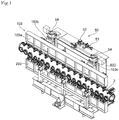
- FIG. 1 is a perspective view of the insertion device according to the present embodiment, from the front surface side.
- FIG. 2 is a perspective view of the same from the rear surface side.
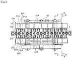
- FIG. 3 is a front view of the same.
- FIG. 4 is a plan view of the same when viewed from above.
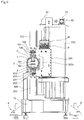
- FIG. 5 is a side view when viewed from the right side.
- FIG. 6 is a cross-sectional view taken along A-A in FIG. 3 .
- FIG. 7 is a cross-sectional view taken along B-B in FIG. 3 .
- FIG. 8 is a cross-sectional view taken along C-C in FIG. 3 .
- the leftward and rightward direction of the paper plane of FIG. 3 shall be the leftward and rightward direction of the insertion device, and the direction perpendicular thereto shall be the forward and rearward direction.
- the insertion device includes a first magnet array M1 constituted by a plurality of magnets placed in an array, and a second magnet array M2 constituted by a plurality of magnets placed in an array similarly, which are facing each other with a gap ⁇ interposed therebetween.
- An electron beam passes through this gap space.
- the magnet arrays it is possible to employ various types of examples of structures, such as ones disclosed in JP 2001-143899 A and JP 2014-13658 A , as well as one disclosed in Patent Document 1, for example. Accordingly, the magnet arrays are not limited to particular placement of magnets.
- the first magnet array M1 is supported by a first magnet supporting member 1, and the second magnet array M2 is supported by a second magnet supporting member 2.
- each of the magnets constituting the first magnet array M1 is coupled to the first magnet supporting member 1, through bolts and the like. The same applies to the second magnet array M2.
- the magnetic arrays which are the first magnet array M1 and the second magnet array M2, are facing each other in the vertical direction.
- the insertion device is not limited to the aforementioned structure and can also include magnet arrays in a horizontal direction or in an oblique direction or a combination of magnet arrays in two or more directions.
- the vacuum vessel 3 is supported on the base 10 through a supporting body 600.
- a supporting member 610 is provided on the supporting body 600, thereby receiving the lower portion of the vacuum vessel 3.
- the supporting body 600, the supporting member 610 and the vacuum vessel 3 are coupled to each other through mechanical means (for example, bolts and nuts) which are not illustrated.
- the supporting body 600 is also coupled to the base 10 through appropriate mechanical means (for example, bolts and nuts).
- Coupling shafts 100 are mounted to an upper portion of the first magnet supporting member 1, and the coupling shafts 100 are coupled at their upper ends to coupling plates 101. As illustrated in FIG. 3 , fourteen coupling shafts 100 are placed along the leftward and rightward direction, and fourteen coupling plates 101 are placed similarly.
- two coupling shafts 100 are placed along the forward and rearward direction when viewed from the front surface side, and these two coupling shafts 100 are coupled to each other through a single coupling plate 101.
- a total of 28 coupling shafts 100 is placed, and the respective two of these 28 coupling shafts 100 are coupled to each other through the fourteen coupling plates 101.
- a first coupling beam 103 is placed above the placement of the coupling shafts 100.
- the first coupling beam 103 and the coupling plates 101 are coupled to each other, through a magnet supporting member guide mechanism 102 such as a linear guide. This is provided for absorbing the change of the length of the first magnet supporting member 1, if the first magnet supporting member 1 changes in length in the horizontal direction due to thermal expansion thereof.
- the gap driving mechanism and the driving conjunction mechanism are prevented from being influenced by the thermal expansion.
- the first magnet supporting member 1 and the first coupling beam 103 are integrally coupled to each other.
- the first coupling beam 103 moves in the vertical direction (an example of the direction in which the magnet arrays are facing each other: the same applies to the following), the first magnet supporting member 1 also moves in the vertical direction integrally therewith, in conjunction with the first coupling beam 103. They move in the vertical direction by the same amount. Further, the mechanism for integrally coupling the first coupling beam 103 and the first magnet supporting member 1 to each other is not limited to the aforementioned structure, and various examples of modifications can be applied thereto.
- the second magnet supporting member 2 is also integrally coupled to a second coupling beam 203, through coupling shafts 200, coupling plates 201, and a magnet supporting member guide mechanism 202.
- the structure thereof is the same as that for the first coupling beam 103 and is not described herein. The same applies to the following description.
- the first coupling beam 103 includes a main-body frame 103a having a rectangular parallelepiped shape extending along the leftward and rightward direction. Further, supporting frames 103b are coupled, at two positions, to the rear side of the main-body frame 103a and are extended along the forward and rearward direction when viewed from the front surface side.
- the gap driving mechanism 50 for changing the size of the aforementioned gap ⁇ , in an upper portion of the rear portion of the insertion device.
- the gap driving mechanism 50 is installed on the base 10 with frames 500 interposed therebetween.
- the frames 500 have a rectangular parallelepiped shape with a rectangular cross section in the horizontal direction, and there are provided two such frames 500.
- a placement plate 501 is provided on the upper portions of the frames 500, and the gap driving mechanism 50 is placed thereon.
- the gap driving mechanism 50 includes a driving motor 51, and conversion portions 52, 53 and 54.
- the conversion portion 52 converts the driving transmission direction by 90 degrees.
- the conversion portion 53 converts the driving transmission direction and transmits the motive power such that it diverges leftwardly and rightwardly.
- the concrete structure thereof is constituted by known mechanical elements such as bevel gears.
- the conversion portions 54 convert the driving transmission into driving transmission in the vertical direction, which drives ball screw mechanisms 7 including a vertical shaft, as illustrated in FIG. 8 , for example.
- the ball screw mechanisms 7 are a well-known structure and are constituted by respective screw shaft portions 70 and respective nut portions 71.
- the screw shaft portions 70 are supported at their upper and lower sides by bearings 70a, and the bearings 70a are mounted to the frames 500.
- the nut portions 71 are mounted to the supporting frames 103b.
- the screw shaft portions 70 are rotated, thereby moving the nut portions 71 upwardly and downwardly. This can move the first coupling beam 103 in the vertical direction.
- the supporting frames 103b see FIG. 1 , FIG. 8 and others, in order to move the first coupling beam 103 in the vertical direction.
- the supporting frames 103b When viewed from the front surface side, the supporting frames 103b are mounted at their rear sides to the front sides of the frames 500 when viewed from the front surface side, through two frame guide mechanisms 103c. When viewed from the front surface side, the supporting frames 103b are mounted, at their front sides, to the first coupling beam 103.
- the driving motor 51 By driving the driving motor 51, the first coupling beam 103 can be moved in the vertical direction, thereby moving the first magnet supporting member 1 and the first magnet array M1 in the vertical direction. Namely, the size of the gap ⁇ can be changed.
- the second coupling beam 203 which is placed in the lower side, can also be moved in the vertical direction, similarly, through a gap driving mechanism (not illustrated) which is placed in the lower side.
- the structure thereof is basically the same as that for the first coupling beam 103 and is not described herein.
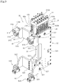
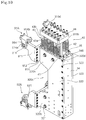
- FIG. 9 is a perspective view illustrating the structure of the spring conjunction mechanism 30 viewed from the front surface side.
- FIG. 10 is a perspective view illustrating the same from the rear surface side.
- FIG. 11 is a side view.
- FIG. 12 is a front view.
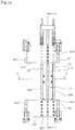
- FIG. 13 is a cross-sectional view taken along F-F in FIG. 12 .
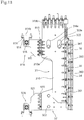
- FIG. 14 is a plan view (seen from above).
- FIG. 15 is a cross-sectional view taken along E-E in FIG. 12 .
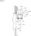
- FIG. 16 is a cross-sectional view taken along D-D in FIG. 11 .
- the spring conjunction mechanism 30 is constituted by a first spring supporting frame 31, and a second spring supporting frame 32.
- the second spring supporting frame 32 includes a pair of second plate portions 320, and the thickness direction thereof corresponds to the leftward and rightward direction.
- the second plate portions 320 are installed in such a way that the plates are erected in the vertical direction.
- the second plate portions 320 include an upper-portion protruding portion 320a, a lower-portion protruding portion 320b, and the concave portion 320c formed therebetween.
- the concave portion 320c is shaped to secure a space for placing the vacuum vessel 3 therein.
- the lower-portion protruding portion 320b and the upper-portion protruding portion 320a are protruded toward the magnet arrays in the same amount.
- the pair of second plate portions 320 are joined together by bolts 321 via shaft-like spacing members 322.
- the bolts 321 are provided at two locations on the lower side and two locations on the upper side.
- the length of the spacing members 322 determines the spacing between the pair of second plate portions 320.
- the pair of second plate portions 320 are integrally coupled to each other, at their rear surface side (their sides farther from the magnet arrays), through a coupling plate 34 (which corresponds to a plate coupling portion).
- the coupling plate 34 and the pair of second plate portions 320 are joined together by a large number of bolts 323.
- the first spring supporting frame 31 includes a single first plate portion 310 and is installed in such a way that the plate is erected in the vertical direction.
- the first plate portion 310 is provided in its upper portion with the upper-portion protruding portion 310a, on its side closer to the magnet arrays (see FIG. 13 ).
- This upper-portion protruding portion 310a protrudes in the same amount as the upper-portion protruding portion 320a of the second plate portion 320.
- the first plate portion 310 is placed in such a way as to be sandwiched between the pair of second plate portions 320, and they are placed with respective predetermined gaps interposed therebetween.
- the first plate portion 310 is positioned right in the middle between the pair of second plate portions 320.
- the spacing members 322 on the lower side are provided at positions where they do not interfere with the first plate portion 310.
- the spacing members 322 on the upper side (at two locations) are formed with long holes 310e that are elongated along the upward and downward direction so as not to interfere with the first plate portion 310.
- the holes are formed as long holes 310e in order to allow relative upward and downward movements of the first plate portion 310 and second plate portions 320, as will be described later.
- a placement plate 35 is placed on the rear side of the first plate portion 310, which is its side farther from the magnet arrays, and a guide mechanism 36 is placed between the placement plate 35 and the coupling plate 34.
- the placement plate 35 and the first plate portion 310 are joined together by a large number of bolts 350.
- the guide mechanism 36 will be referred to as a vertical guide mechanism 36, in order to distinguish it from guide mechanisms installed in other portions for facilitating understanding. However, it is not intended that the guide mechanism 36 should be installed restrictively in the vertical direction.
- the vertical guide mechanism 36 can be constituted by a linear guide, for example, such that a guide rail 360 therein is placed on the coupling plate 34, and a guide block 361 therein is placed on the first plate portion 310 (see FIGS. 13 and 15 ). Further, the guide rail and the guide block can also be interchanged in placement.
- the vertical guide mechanism 36 can also be constituted by other guide mechanisms than linear guides.
- the vertical guide mechanism 36 corresponds to a guide mechanism for guiding the relative movement of the first spring supporting frame 31 and the second spring supporting frame 32 in the vertical direction (in which the magnet arrays are facing each other).
- the first spring supporting frame 31 can be moved relative to the second spring supporting frame 32 in the vertical direction.
- the second plate portions 320 are provided, at their upper end faces, with respective spring placement portions 320d. Further, the first plate portion 310 is provided at its upper end portion with a compressive-force exertion portion 310b.
- the compressive-force exertion portion 310b is formed to have a plate shape with a horizontal surface. Compensation springs 42 are placed between the spring placement portions 320d and the compressive-force exertion portion 310b. Accordingly, the compressive-force exertion portion 310b also functions as a spring placement portion.
- Compensation spring mechanism 40 which constitutes the compensation module 8 together with the spring conjunction mechanism 30, with reference to FIG. 9 .
- Spring installation plates 41 are provided on the upper surfaces of the spring placement portions 320d.
- a plurality of compensation springs 42 are installed on the spring installation plates 41.
- Six compensation springs 42 are placed in the forward and rearward direction when viewed from the front surface side. Incidentally, the number of the compensation springs placed thereon can be properly determined. As illustrated in the plan view of FIG. 4 which illustrates them from above, the compensation modules 8 (the spring conjunction mechanisms 30 and the compensation spring mechanisms 40) are placed at four positions in the leftward and rightward direction (the direction of propagation of the electron beam).
- the number of the compensation modules placed therein can be properly determined, depending on the length of the insertion device in the leftward and rightward direction.
- the compensation springs 42 are arranged in two rows (since there is the pair of the second plate portions 320), and there is a total of 12 compensation springs 42.
- the compensation springs 42 are constituted by compression coil springs.
- the compensation springs 42 are placed at their lower end portions on the spring installation plates 41.
- Respective pushers 43 are placed on the upper end portions of the compensation springs 42.
- the pushers 43 are each constituted by a pressing portion 43a and a bolt portion 43b, which are integrally formed.
- the pressing portions 43a are structured to press the upper end portions of the compensation springs 42.
- the pushers 43 can be fastened to the compressive-force exertion portion 310b, through the bolt portions 43b.
- the pushers 43 can be positioned and secured through nuts 44.
- the amounts of initial compression of the respective compensation springs 42 can be adjusted, through the pushers 43.
- the compressive-force exertion portion 310b is joined to the upper end face of the first plate portion 310 by bolts 310d at six locations.
- the first spring supporting frame 31 is mounted to a first auxiliary frame 91 on the upper side
- the second spring supporting frame 32 is mounted to a second auxiliary frame 92 on the lower side.
- the first and second spring supporting frames 31 and 32 are mounted to the first and second coupling beams 103 and 203 not directly but via the first and second auxiliary frames 91 and 92. Since the first auxiliary frame 91 and second auxiliary frame 92 have the same basic structure, the first auxiliary frame 91 will be mainly described.
- the first auxiliary frame 91 is configured by a first left and right plate 910 and a pair of first front and back plates 911.
- the pair of first front and back plates 911 are joined to the first left and right plate 910 at its left and right end portions by bolts 912 (see FIG. 10 ). With these plates joined, the first auxiliary frame has a gate-like shape in plan view from above. Therefore, there is formed a space between the pair of first front and back plates 911.
- the second auxiliary frame 92 similarly, is configured by a second left and right plate 920 and a pair of second front and back plates 921.
- first left and right plate 910 Three rows of five holes formed along the upward and downward direction are provided in the leftward and right plate 910. Note that, the number of holes and the number of rows of holes and the like are not limited to those in the present embodiment.
- the first plate portion 310 of the first spring supporting frame 31 is joined to the first left and right plate 910 by bolts 913 (see FIG. 12 ), using the middle row of the three rows of holes.
- the second plate portions 320 of the second spring supporting frame 32 are joined by bolts 923 (see FIG. 12 ), using the left and right rows of the three rows of holes. Accordingly, the same member can be used as the first left and right plate 910 and the second left and right plate 920.
- the first coupling portions 91A are provided to distal end portions of the pair of first front and back plates 911 on the left and right.
- the first coupling portion 91A includes a coupling member 914 and a coupling shaft 915.
- the coupling member 914 is integrally formed with a shaft bore portion 914a (see FIG. 10 ) and a planar portion 914b.
- the planar portion 914b is coupled to the first coupling beam 103 from the lower surface side by bolts 916.
- the coupling shaft 915 is inserted in a hole 911a formed in the first front and back plate 911 such that it is allowed to slide.
- the coupling shaft 915 has such an outside diameter that there is formed a clearance between the coupling shaft 915 and the hole 914c in the coupling member 914 when the shaft fits therein.
- Bolts 917 are positioned below the coupling shaft 915 so that the coupling member 914 and the coupling shaft 915 are secured by the bolts 917.
- the first front and back plate 911 is not secured and allowed to rotate.
- second coupling portions 92A To join the second auxiliary frame 92 on the lower side to the second coupling beam 203, there is provided a pair of second coupling portions 92A.
- the second coupling portions 92A are positioned above the second coupling beam 203.
- the structure of the second coupling portion 92A is the same as that of the first coupling portion 91A, and is not described herein.
- the spring conjunction mechanism 30 and the first and second coupling beams 103 and 203 are coupled to each other.
- the compensation spring mechanisms 40 and the first magnet supporting member 1 and the second magnet supporting member 2 are coupled to each other through the spring conjunction mechanisms 30, with various members such as the coupling beams 103 and 203 interposed therebetween.
- the first auxiliary frame 91 and second auxiliary frame 92 are allowed to rotate and move, rather than being completely secured to the first coupling beam 103 and the second coupling beam 203, respectively.
- the compensation modules 8 are all installed on the rear side of the magnet arrays (on the side of the frames 500 with respect to the vacuum vessel 3).
- the compensation modules 8 can also be installed on the front side (on the opposite side from the frames 500 with respect to the vacuum vessel 3) or can be installed on the both sides of the vacuum vessel 3, depending on the structure of the insertion device in which the compensation modules 8 are installed and depending on the required sizes of the spring forces.
- the coupling shafts 100, coupling plates 101, magnet supporting member guide mechanism 102, and so on are provided as a magnet/beam coupling mechanism for coupling the first magnet supporting member 1 and the first coupling beam 103.
- the first coupling portions 91A and second coupling portions 92A are placed in the space between the magnet/beam coupling mechanisms (see also FIG. 14 ).
- the compensation spring mechanisms 40 are not placed in this space. If there were no auxiliary frames, the first spring supporting frame 31 and second spring supporting frame 32 would be placed between adjacent magnet/beam coupling mechanisms, which naturally would cause the compensation spring mechanism 40 to be placed in this space. However, the position of the compensation spring mechanism 40 where deformation of the magnet supporting members can be minimized is not necessarily between the adjacent magnet/beam coupling mechanisms.
- an optimal position of the compensation spring mechanism 40 could be determined by simulation. Namely, it has been found out that there has been an optimal position for the compensation spring mechanism 40 where deformation of coupling beams 103 and 203 could be most suppressed, depending on the lengths of the coupling beams 103 and 203, mounting positions of the coupling shafts 100 and 200, the number of compensation spring mechanisms 40 to be placed, and so on.
- the first and second coupling portions 91A and 92A cannot be placed at the positions where the magnet/beam coupling mechanisms (coupling shafts 100 and 200 and others) will be placed, because of which the optimal positions of the coupling shafts 100 and 200 sometimes conflict with the optimal positions of the coupling portions 91A and 92A. For this reason, previously, there has been the problem that the compensation spring mechanism 40 could not be placed at an optimal position and deformation of the coupling beams 103 and 203 could not be minimized.
- the configuration of the present invention provides flexibility to the possible placement position of the compensation spring mechanism 40.
- the compensation spring mechanism 40 is placed substantially behind the coupling shaft 100. While the compensation spring mechanism 40 could normally not be placed at this location (the position that conflicts with the position of the coupling shaft 100 in front view) without the auxiliary frames, the configuration of the present invention enables such placement.
- the mounting point of the compensation spring mechanism 40 can be changed within the range of width W of the first left and right plate 910, as is understood also from FIG. 14 . It only requires a design change wherein the rows of holes for mounting the first and second spring supporting frames 31 and 32 are matched with the optimal position.
- the first plate portion 310 is moved downwardly since the first coupling beam 103 is moved downwardly.
- the second plate portions 320 are moved upwardly since the second coupling beam 203 is moved upwardly.
- the compensation springs 42 in the compensation spring mechanisms 40 are compressed.
- the gap ⁇ is made smaller, the attractive force from the magnets is made larger and, in conjunction therewith, the spring forces in the compensation spring mechanisms 40 are made larger. If the attractive force is made larger, this exerts forces which attempt to deform the coupling beams, which are integrally coupled to the magnet supporting bodies supporting the magnet arrays.
- the magnet supporting bodies are also deformed, which makes the size of the gap ⁇ non-constant in the rightward and leftward direction, which is the direction of the electron beam, thereby making it impossible to maintain the magnetic-field intensity distribution in the direction of the electron beam which has been initially set.
- the compensation spring mechanisms 40 are provided, in order to suppress the deformations of the coupling beams due to attractive forces.
- first and second coupling portions 91A, 92A are constituted by coupling structures including a shaft and a fitting hole.
- the first and second coupling portions 91A, 92A are provided on the lower end portion of the first coupling beam 103 and on the upper end portion of the second coupling beam 203, respectively. Namely, both of the first and second coupling portions are provided in the side closer to the magnet arrays. This can inhibit the increase of the sizes of the first spring supporting frame 31 and the second spring supporting frame 32 in the upward and downward direction.
- the compensation spring mechanisms 40 are provided in the rear side with respect to the vacuum vessel 3 when viewed from the front surface side. When viewed from the front surface side, the front side with respect to the vacuum vessel 3 is opened. This prevents the compensation spring mechanisms 40 from obstructing works which necessitate accessing the vacuum vessel 3 and the magnet arrays from the front side when viewed from the front surface side.
- the respective elements constituting the spring conjunction mechanisms 30 it is possible to properly determine the materials thereof, the methods for fabricating them, and the constitutions of members therein, such as whether the respective elements are constituted by a single member or by a combination of plural members, for example.
- the mechanism may be integrally formed of a single component, or may be formed by connecting a plurality of components with bolts or the like.
Landscapes
- Physics & Mathematics (AREA)
- Optics & Photonics (AREA)
- Engineering & Computer Science (AREA)
- Plasma & Fusion (AREA)
- Spectroscopy & Molecular Physics (AREA)
- Particle Accelerators (AREA)
Abstract
Description
- The present invention relates to insertion devices including a first magnet array constituted by a plurality of magnets placed in an array, a first magnet supporting member for supporting the first magnet array mounted thereto, a second magnet array which is constituted by a plurality of magnets placed in an array and facing the first magnet array with a gap interposed therebetween, a second magnet supporting member for supporting the second magnet array mounted thereto, a gap driving mechanism for driving the first magnet supporting member and/or the second magnet supporting member in the direction in which the magnet arrays are facing each other, in order to change the size of the gap, and a driving conjunction mechanism for coupling the gap driving mechanism and the magnet supporting members to each other.
- If an electron beam having been accelerated to near the light velocity in a vacuum is bent within a magnet field, radiated light is emitted in tangential directions of the trajectory of the movement of the electron beam. This is called synchrotron radiation. There have been made studies for practical applications of various techniques for installing light sources for generating such synchrotron radiation in straight sections of electron storage rings (electron-beam accumulating rings), in order to utilize their properties such as high directivity, high intensity, and high polarization properties. Existing electron storage rings have been provided with plural insertion devices (undulators), as high-brightness light sources with higher beam electric currents and smaller beam cross-sectional areas.
- As such insertion devices, there has been known an insertion device disclosed in the following Non-Patent
Document 1, for example. This insertion device has a structure including a first magnet array constituted by a plurality of magnets placed in an array, and a second magnet array constituted by a plurality of magnets placed in an array, which are facing each other with a gap interposed therebetween. Since the arrays of the plural magnets are facing each other, large attractive forces are exerted between both of them. - Due to the exertion of the attractive forces, large loads are induced in gap driving mechanisms, which causes degradation of precise gap driving and deformations of magnet supporting members supporting the magnet arrays, thereby disordering the magnetic-field intensity distribution in the direction of an electron beam, which has been initially set in the magnetic-field generating space (the gap). This has resulted in the problem of impossibility of generation of synchrotron radiation with desired properties.
- The following
Patent Document 1 discloses a structure provided with a compensation spring mechanism, in order to overcome the aforementioned problem. The magnet supporting members mentioned above are coupled to coupling beams via mechanisms (coupling shafts) that are vertical to the coupling beams, and the size of the gap is changed by moving the coupling beams in the vertical direction. The compensation spring mechanism is also coupled to the coupling beams via coupling portions. - As is understood from
FIG. 3 of the followingPatent Document 1, the coupling portions of the compensation spring mechanisms are placed between a plurality of coupling shafts. This is because they physically interfere with each other. Therefore, the positions of the coupling shafts once determined, inevitably and substantially determine the positions of the coupling portions and the compensation spring mechanisms. - Patent Document 1:
WO2018/143253 A1 - Non-Patent Document 1: Winick, Herman; George Brown; Klaus Halbach; John Harris (May 1981). "Synchrotron Radiation Wiggler and Undulator Magnets" Physics Today, May 1981,
- The inventors of the present invention have found out that optimal positions of the compensation spring mechanisms relative to the positions of the coupling shafts in the insertion device having the configuration described above could be determined by simulation. Namely, it has been found out that there have been optimal positions for the compensation spring mechanisms where deformation of coupling beams could be most suppressed, depending on the length of the coupling beams, mounting positions of the coupling shafts, the number of compensation spring mechanisms to be placed, and so on.
- However, since the coupling portions cannot be placed at positions where the coupling shafts will be placed as described above, the optimal positions of the coupling shafts and the optimal positions of the compensation spring mechanisms sometimes conflict with each other. For this reason, there has been the problem that the compensation spring mechanisms could not be placed at optimal positions and deformation of the coupling beams could not be minimized.
- The present invention has been made in view of the circumstances described above, and it is an object of the present invention to provide an insertion device that can minimize deformation of coupling beams through optimization of the position of the compensation spring mechanism.
- In order to solve the above problem, an insertion device according to the present invention includes:
- a first magnet array including a plurality of magnets placed in an array;
- a first magnet supporting member adapted to support the first magnet array mounted to the first magnet supporting member;
- a second magnet array including a plurality of magnets placed in an array and facing the first magnet array with a gap interposed therebetween;
- a second magnet supporting member adapted to support the second magnet array mounted to the second magnet supporting member;
- a gap driving mechanism for driving the first magnet supporting member and/or the second magnet supporting member in a direction in which the magnet arrays are facing each other, in order to change a size of the gap;
- a first coupling beam coupled integrally to the first magnet supporting member;
- a second coupling beam coupled integrally to the second magnet supporting member;
- a driving conjunction mechanism for coupling at least one of the first coupling beam and the second coupling beam to the gap driving mechanism;
- a compensation spring mechanism adapted to act in such a direction as to cancel an attractive force acting between the first magnet array and the second magnet array; and
- a spring conjunction mechanism for coupling the compensation spring mechanism and the coupling beams to each other, wherein
- the spring conjunction mechanism includes:
- a first auxiliary frame coupled, through a pair of first coupling portions, to one of the first coupling beam and the second coupling beam;
- a second auxiliary frame coupled, through a pair of second coupling portions, to the other one of the first coupling beam and the second coupling beam;
- a first spring supporting frame mounted to the first auxiliary frame;
- a second spring supporting frame mounted to the second auxiliary frame; and
- a guide mechanism for guiding relative movement of the first spring supporting frame and the second spring supporting frame, in the direction in which the magnet arrays are facing each other,
- wherein the compensation spring mechanism is mounted to both the first spring supporting frame and the second spring supporting frame and configured to operate, when the size of the gap is changed, by allowing relative movement of the first spring supporting frame and the second spring supporting frame, in the direction in which the magnet arrays are facing each other,
- wherein the first auxiliary frame is capable of placing a mechanism for coupling the first magnet supporting member and the first coupling beam to each other between the pair of first coupling portions, and
- wherein the second auxiliary frame is capable of placing a mechanism for coupling the second magnet supporting member and the second coupling beam to each other between the pair of second coupling portions.
- With the insertion device having the aforementioned structure, it is possible to provide effects and advantages as follows. The first magnet supporting member is integrally coupled to the first coupling beam, and the second magnet supporting member is integrally coupled to the second coupling beam.
- The gap driving mechanism drives at least one of the first coupling beam and the second coupling beam for changing the size of the gap. The spring conjunction mechanism includes the first spring supporting frame and the second spring supporting frame, which are mounted to the first auxiliary frame and the second auxiliary frame, respectively.
- These first auxiliary frame and second auxiliary frame are coupled to the first coupling beam and the second coupling beam via the pairs of first coupling portions and second coupling portions, respectively. Further, the first spring supporting frame and the second spring supporting frame are allowed to move relative to each other, through the guide mechanism, in the direction in which the magnet arrays are facing each other.
- With this structure, moments induced by the operations of the compensation spring mechanism can be received by the guide mechanism, which inhibits such moments from influencing the gap driving mechanism through the first and second coupling portions. This can prevent the operations of the compensation spring from influencing the precise gap driving.
- Further, the first auxiliary frame and second auxiliary frame are formed to make a space available for placing a mechanism for coupling the magnet supporting member and the coupling beam to each other. The compensation spring mechanism can thus be placed in a location other than the space noted above, which makes it possible to optimally place the compensation spring mechanism.
- Further, the direction in which the magnet arrays are facing each other depends on the state where the magnet arrays are installed. The direction in which the magnet arrays are facing each other includes the vertical direction, the horizontal direction and arbitrary oblique directions, for example. Further, movements in the direction in which the magnet arrays are facing each other include both cases where the magnet arrays get closer to each other and cases where the magnet arrays get farther away from each other.
- In the present invention, preferably, the first auxiliary frame includes a pair of first front and back plates extending in a forward and rearward direction, and a first left and right plate extending in a leftward and rightward direction for coupling the pair of first front and back plates to each other,
the second auxiliary frame includes a pair of second front and back plates extending in a forward and rearward direction, and a second left and right plate extending in a leftward and rightward direction for coupling the pair of second front and back plates to each other,
the pair of first front and back plates is coupled to the first coupling beam via the first coupling portions, and
the pair of second front and back plates is coupled to the second coupling beam via the second coupling portions. - The auxiliary frame having this configuration allows a mechanism for coupling the magnet supporting member and the coupling beam to each other to be placed between a pair of front and back plates. Also, the spring supporting frame can be mounted to a left and right plate, so that an optimal position as its mounting position can be determined.
- In the present invention, preferably, the first auxiliary frame and the second auxiliary frame have a gate-like shape in plan view.
- By having a gate-like shape, it is possible to secure a space for placing a mechanism for coupling the magnet supporting member and the coupling beam to each other.
- In the present invention, preferably, the first left and right plate and the second left and right plate are formed with both mounting holes for mounting the first spring supporting frame and mounting holes for mounting the second spring supporting frame.
- This enables production of the first left and right plate and second left and right plate from a common member, which contributes to better parts management and cost reduction.
-
- FIG. 1
- is a perspective view of the front surface side of an insertion device according to the present embodiment;
- FIG. 2
- is a perspective view of the rear surface side of the insertion device according to the present embodiment;
- FIG. 3
- is a front view of the insertion device according to the present embodiment;
- FIG. 4
- is a plan view seen from above of the insertion device according to the present embodiment;
- FIG. 5
- is a side view of the insertion device according to the present embodiment;
- FIG. 6
- is a cross-sectional view taken along A-A in
FIG. 3 ; - FIG. 7
- is a cross-sectional view taken along B-B in
FIG. 3 ; - FIG. 8
- is a cross-sectional view taken along C-C in
FIG. 3 ; - FIG. 9
- is a perspective view of the front surface side illustrating the structure of the spring conjunction mechanism;
- FIG. 10
- is a perspective view of the rear surface side illustrating the structure of the spring conjunction mechanism;
- FIG. 11
- is a side view illustrating the structure of the spring conjunction mechanism;
- FIG. 12
- is a rear view illustrating the structure of the spring conjunction mechanism;
- FIG. 13
- is a cross-sectional view taken along F-F in
FIG. 12 ; - FIG. 14
- is a plan view seen from above illustrating the structure of the spring conjunction mechanism;
- FIG. 15
- is a cross-sectional view taken along E-E in
FIG. 12 ; and - FIG. 16
- is a cross-sectional view taken along D-D in
FIG. 11 . - A preferred embodiment of an insertion device according to the present invention will be described with reference to the drawings.
FIG. 1 is a perspective view of the insertion device according to the present embodiment, from the front surface side.FIG. 2 is a perspective view of the same from the rear surface side.FIG. 3 is a front view of the same.FIG. 4 is a plan view of the same when viewed from above.FIG. 5 is a side view when viewed from the right side. -
FIG. 6 is a cross-sectional view taken along A-A inFIG. 3 .FIG. 7 is a cross-sectional view taken along B-B inFIG. 3 .FIG. 8 is a cross-sectional view taken along C-C inFIG. 3 . In the following description, for convenience of explanation, the leftward and rightward direction of the paper plane ofFIG. 3 shall be the leftward and rightward direction of the insertion device, and the direction perpendicular thereto shall be the forward and rearward direction. - As illustrated in
FIG. 5 , the insertion device includes a first magnet array M1 constituted by a plurality of magnets placed in an array, and a second magnet array M2 constituted by a plurality of magnets placed in an array similarly, which are facing each other with a gap δ interposed therebetween. An electron beam passes through this gap space. Further, as the magnet arrays, it is possible to employ various types of examples of structures, such as ones disclosed inJP 2001-143899 A JP 2014-13658 A Patent Document 1, for example. Accordingly, the magnet arrays are not limited to particular placement of magnets. - The first magnet array M1 is supported by a first
magnet supporting member 1, and the second magnet array M2 is supported by a secondmagnet supporting member 2. For example, each of the magnets constituting the first magnet array M1 is coupled to the firstmagnet supporting member 1, through bolts and the like. The same applies to the second magnet array M2. - Further, the magnetic arrays, which are the first magnet array M1 and the second magnet array M2, are facing each other in the vertical direction. However, the insertion device is not limited to the aforementioned structure and can also include magnet arrays in a horizontal direction or in an oblique direction or a combination of magnet arrays in two or more directions.
- Further, the
vacuum vessel 3 is supported on the base 10 through a supportingbody 600. As also illustrated inFIG. 5 , a supportingmember 610 is provided on the supportingbody 600, thereby receiving the lower portion of thevacuum vessel 3. The supportingbody 600, the supportingmember 610 and thevacuum vessel 3 are coupled to each other through mechanical means (for example, bolts and nuts) which are not illustrated. Further, the supportingbody 600 is also coupled to the base 10 through appropriate mechanical means (for example, bolts and nuts). - Coupling
shafts 100 are mounted to an upper portion of the firstmagnet supporting member 1, and thecoupling shafts 100 are coupled at their upper ends tocoupling plates 101. As illustrated inFIG. 3 , fourteencoupling shafts 100 are placed along the leftward and rightward direction, and fourteencoupling plates 101 are placed similarly. - As illustrated in
FIG. 5 and others, twocoupling shafts 100 are placed along the forward and rearward direction when viewed from the front surface side, and these twocoupling shafts 100 are coupled to each other through asingle coupling plate 101. Namely, in the example illustrated inFIGS. 3 and5 , a total of 28coupling shafts 100 is placed, and the respective two of these 28coupling shafts 100 are coupled to each other through the fourteencoupling plates 101. - A
first coupling beam 103 is placed above the placement of thecoupling shafts 100. Thefirst coupling beam 103 and thecoupling plates 101 are coupled to each other, through a magnet supportingmember guide mechanism 102 such as a linear guide. This is provided for absorbing the change of the length of the firstmagnet supporting member 1, if the firstmagnet supporting member 1 changes in length in the horizontal direction due to thermal expansion thereof. - Accordingly, the gap driving mechanism and the driving conjunction mechanism are prevented from being influenced by the thermal expansion. As described above, the first
magnet supporting member 1 and thefirst coupling beam 103 are integrally coupled to each other. - If the
first coupling beam 103 moves in the vertical direction (an example of the direction in which the magnet arrays are facing each other: the same applies to the following), the firstmagnet supporting member 1 also moves in the vertical direction integrally therewith, in conjunction with thefirst coupling beam 103. They move in the vertical direction by the same amount. Further, the mechanism for integrally coupling thefirst coupling beam 103 and the firstmagnet supporting member 1 to each other is not limited to the aforementioned structure, and various examples of modifications can be applied thereto. - The second
magnet supporting member 2 is also integrally coupled to asecond coupling beam 203, throughcoupling shafts 200,coupling plates 201, and a magnet supportingmember guide mechanism 202. The structure thereof is the same as that for thefirst coupling beam 103 and is not described herein. The same applies to the following description. - As illustrated in
FIG. 1 , thefirst coupling beam 103 includes a main-body frame 103a having a rectangular parallelepiped shape extending along the leftward and rightward direction. Further, supportingframes 103b are coupled, at two positions, to the rear side of the main-body frame 103a and are extended along the forward and rearward direction when viewed from the front surface side. - There is provided the
gap driving mechanism 50 for changing the size of the aforementioned gap δ, in an upper portion of the rear portion of the insertion device. Thegap driving mechanism 50 is installed on the base 10 withframes 500 interposed therebetween. As illustrated inFIG. 2 , theframes 500 have a rectangular parallelepiped shape with a rectangular cross section in the horizontal direction, and there are provided twosuch frames 500. Aplacement plate 501 is provided on the upper portions of theframes 500, and thegap driving mechanism 50 is placed thereon. - The
gap driving mechanism 50 includes a drivingmotor 51, andconversion portions conversion portion 52 converts the driving transmission direction by 90 degrees. Theconversion portion 53 converts the driving transmission direction and transmits the motive power such that it diverges leftwardly and rightwardly. There are provided a pair of theconversion portions 54 in the left and right sides which are adapted to convert the driving in the horizontal direction into driving in the vertical direction. The concrete structure thereof is constituted by known mechanical elements such as bevel gears. - The
conversion portions 54 convert the driving transmission into driving transmission in the vertical direction, which drivesball screw mechanisms 7 including a vertical shaft, as illustrated inFIG. 8 , for example. Theball screw mechanisms 7 are a well-known structure and are constituted by respectivescrew shaft portions 70 andrespective nut portions 71. Thescrew shaft portions 70 are supported at their upper and lower sides bybearings 70a, and thebearings 70a are mounted to theframes 500. Thenut portions 71 are mounted to the supportingframes 103b. - By driving the
ball screw mechanisms 7, thescrew shaft portions 70 are rotated, thereby moving thenut portions 71 upwardly and downwardly. This can move thefirst coupling beam 103 in the vertical direction. There are provided the supportingframes 103b (seeFIG. 1 ,FIG. 8 and others), in order to move thefirst coupling beam 103 in the vertical direction. - When viewed from the front surface side, the supporting
frames 103b are mounted at their rear sides to the front sides of theframes 500 when viewed from the front surface side, through twoframe guide mechanisms 103c. When viewed from the front surface side, the supportingframes 103b are mounted, at their front sides, to thefirst coupling beam 103. - The
ball screw mechanisms 7, which are driven by theframe guide mechanisms 103c and theconversion portions 54 as described above, correspond to a driving conjunction mechanism for coupling thefirst coupling beam 103 and thegap driving mechanism 50 to each other. By driving the drivingmotor 51, thefirst coupling beam 103 can be moved in the vertical direction, thereby moving the firstmagnet supporting member 1 and the first magnet array M1 in the vertical direction. Namely, the size of the gap δ can be changed. - Further, the
second coupling beam 203, which is placed in the lower side, can also be moved in the vertical direction, similarly, through a gap driving mechanism (not illustrated) which is placed in the lower side. The structure thereof is basically the same as that for thefirst coupling beam 103 and is not described herein. By moving thefirst coupling beam 103 and thesecond coupling beam 203 in the vertical direction using the aforementioned structure, it is possible to change the size of the gap δ. By moving thefirst coupling beam 103 and thesecond coupling beam 203 in such a direction that they get closer to each other, the gap δ can be made smaller. By moving them in such a direction that they get farther away from each other, the gap δ can be made larger. - Next, as a preferred embodiment of compensation modules according to the present invention, there will be described, at first, a
spring conjunction mechanism 30, out ofcompensation spring mechanisms 40 andspring conjunction mechanisms 30 which constitutecompensation modules 8, mainly with reference toFigs. 9 to 15 .FIG. 9 is a perspective view illustrating the structure of thespring conjunction mechanism 30 viewed from the front surface side.FIG. 10 is a perspective view illustrating the same from the rear surface side. -
FIG. 11 is a side view.FIG. 12 is a front view.FIG. 13 is a cross-sectional view taken along F-F inFIG. 12 .FIG. 14 is a plan view (seen from above).FIG. 15 is a cross-sectional view taken along E-E inFIG. 12 .FIG. 16 is a cross-sectional view taken along D-D inFIG. 11 . These drawings are drawings for explaining the compensation module and do not show other mechanisms. - The
spring conjunction mechanism 30 is constituted by a firstspring supporting frame 31, and a secondspring supporting frame 32. The secondspring supporting frame 32 includes a pair ofsecond plate portions 320, and the thickness direction thereof corresponds to the leftward and rightward direction. Thesecond plate portions 320 are installed in such a way that the plates are erected in the vertical direction. Thesecond plate portions 320 include an upper-portion protruding portion 320a, a lower-portion protruding portion 320b, and theconcave portion 320c formed therebetween. As also illustrated inFIG. 5 , theconcave portion 320c is shaped to secure a space for placing thevacuum vessel 3 therein. As illustrated inFIGS. 9 ,11 and others, the lower-portion protruding portion 320b and the upper-portion protruding portion 320a are protruded toward the magnet arrays in the same amount. - As illustrated in
FIG. 9 , the pair ofsecond plate portions 320 are joined together bybolts 321 via shaft-like spacing members 322. Thebolts 321 are provided at two locations on the lower side and two locations on the upper side. The length of thespacing members 322 determines the spacing between the pair ofsecond plate portions 320. - As illustrated in
FIG. 10 , the pair ofsecond plate portions 320 are integrally coupled to each other, at their rear surface side (their sides farther from the magnet arrays), through a coupling plate 34 (which corresponds to a plate coupling portion). Thecoupling plate 34 and the pair ofsecond plate portions 320 are joined together by a large number ofbolts 323. - The first
spring supporting frame 31 includes a singlefirst plate portion 310 and is installed in such a way that the plate is erected in the vertical direction. Thefirst plate portion 310 is provided in its upper portion with the upper-portion protruding portion 310a, on its side closer to the magnet arrays (seeFIG. 13 ). This upper-portion protruding portion 310a protrudes in the same amount as the upper-portion protruding portion 320a of thesecond plate portion 320. - As can be seen also from
FIG. 12 , thefirst plate portion 310 is placed in such a way as to be sandwiched between the pair ofsecond plate portions 320, and they are placed with respective predetermined gaps interposed therebetween. Thefirst plate portion 310 is positioned right in the middle between the pair ofsecond plate portions 320. - As illustrated in
FIG. 13 , the spacingmembers 322 on the lower side are provided at positions where they do not interfere with thefirst plate portion 310. The spacingmembers 322 on the upper side (at two locations) are formed withlong holes 310e that are elongated along the upward and downward direction so as not to interfere with thefirst plate portion 310. The holes are formed aslong holes 310e in order to allow relative upward and downward movements of thefirst plate portion 310 andsecond plate portions 320, as will be described later. - As illustrated in
FIG. 13 , aplacement plate 35 is placed on the rear side of thefirst plate portion 310, which is its side farther from the magnet arrays, and aguide mechanism 36 is placed between theplacement plate 35 and thecoupling plate 34. Theplacement plate 35 and thefirst plate portion 310 are joined together by a large number ofbolts 350. - Incidentally, in the following description, the
guide mechanism 36 will be referred to as avertical guide mechanism 36, in order to distinguish it from guide mechanisms installed in other portions for facilitating understanding. However, it is not intended that theguide mechanism 36 should be installed restrictively in the vertical direction. - The
vertical guide mechanism 36 can be constituted by a linear guide, for example, such that aguide rail 360 therein is placed on thecoupling plate 34, and aguide block 361 therein is placed on the first plate portion 310 (seeFIGS. 13 and15 ). Further, the guide rail and the guide block can also be interchanged in placement. Thevertical guide mechanism 36 can also be constituted by other guide mechanisms than linear guides. Thevertical guide mechanism 36 corresponds to a guide mechanism for guiding the relative movement of the firstspring supporting frame 31 and the secondspring supporting frame 32 in the vertical direction (in which the magnet arrays are facing each other). - With this structure, the first
spring supporting frame 31 can be moved relative to the secondspring supporting frame 32 in the vertical direction. - The
second plate portions 320 are provided, at their upper end faces, with respectivespring placement portions 320d. Further, thefirst plate portion 310 is provided at its upper end portion with a compressive-force exertion portion 310b. The compressive-force exertion portion 310b is formed to have a plate shape with a horizontal surface. Compensation springs 42 are placed between thespring placement portions 320d and the compressive-force exertion portion 310b. Accordingly, the compressive-force exertion portion 310b also functions as a spring placement portion. - There will be described the
compensation spring mechanism 40 which constitutes thecompensation module 8 together with thespring conjunction mechanism 30, with reference toFIG. 9 .Spring installation plates 41 are provided on the upper surfaces of thespring placement portions 320d. A plurality of compensation springs 42 are installed on thespring installation plates 41. - Six compensation springs 42 are placed in the forward and rearward direction when viewed from the front surface side. Incidentally, the number of the compensation springs placed thereon can be properly determined. As illustrated in the plan view of
FIG. 4 which illustrates them from above, the compensation modules 8 (thespring conjunction mechanisms 30 and the compensation spring mechanisms 40) are placed at four positions in the leftward and rightward direction (the direction of propagation of the electron beam). - The number of the compensation modules placed therein can be properly determined, depending on the length of the insertion device in the leftward and rightward direction. With respect to the
compensation spring mechanism 40 at a single position, the compensation springs 42 are arranged in two rows (since there is the pair of the second plate portions 320), and there is a total of 12 compensation springs 42. - The compensation springs 42 are constituted by compression coil springs. The compensation springs 42 are placed at their lower end portions on the
spring installation plates 41.Respective pushers 43 are placed on the upper end portions of the compensation springs 42. Thepushers 43 are each constituted by apressing portion 43a and abolt portion 43b, which are integrally formed. Thepressing portions 43a are structured to press the upper end portions of the compensation springs 42. - The
pushers 43 can be fastened to the compressive-force exertion portion 310b, through thebolt portions 43b. Thepushers 43 can be positioned and secured through nuts 44. The amounts of initial compression of the respective compensation springs 42 can be adjusted, through thepushers 43. The compressive-force exertion portion 310b is joined to the upper end face of thefirst plate portion 310 bybolts 310d at six locations. - Next, there will be described the structure for coupling the
spring conjunction mechanism 30 to the first and second coupling beams 103 and 203. As illustrated inFIG. 9 , the firstspring supporting frame 31 is mounted to a firstauxiliary frame 91 on the upper side, and the secondspring supporting frame 32 is mounted to a secondauxiliary frame 92 on the lower side. - Namely, the first and second
spring supporting frames auxiliary frames auxiliary frame 91 and secondauxiliary frame 92 have the same basic structure, the firstauxiliary frame 91 will be mainly described. - The first
auxiliary frame 91 is configured by a first left andright plate 910 and a pair of first front andback plates 911. The pair of first front andback plates 911 are joined to the first left andright plate 910 at its left and right end portions by bolts 912 (seeFIG. 10 ). With these plates joined, the first auxiliary frame has a gate-like shape in plan view from above. Therefore, there is formed a space between the pair of first front andback plates 911. The secondauxiliary frame 92, similarly, is configured by a second left andright plate 920 and a pair of second front andback plates 921. - Three rows of five holes formed along the upward and downward direction are provided in the leftward and rightward direction in the first left and
right plate 910. Note that, the number of holes and the number of rows of holes and the like are not limited to those in the present embodiment. As illustrated inFIG. 12 , thefirst plate portion 310 of the firstspring supporting frame 31 is joined to the first left andright plate 910 by bolts 913 (seeFIG. 12 ), using the middle row of the three rows of holes. - The
second plate portions 320 of the secondspring supporting frame 32 are joined by bolts 923 (seeFIG. 12 ), using the left and right rows of the three rows of holes. Accordingly, the same member can be used as the first left andright plate 910 and the second left andright plate 920. - To join the first
auxiliary frame 91 to thefirst coupling beam 103, there is provided a pair offirst coupling portions 91A. Thefirst coupling portions 91A are provided to distal end portions of the pair of first front andback plates 911 on the left and right. Thefirst coupling portion 91A includes acoupling member 914 and acoupling shaft 915. Thecoupling member 914 is integrally formed with ashaft bore portion 914a (seeFIG. 10 ) and aplanar portion 914b. Theplanar portion 914b is coupled to thefirst coupling beam 103 from the lower surface side bybolts 916. - As illustrated in
FIG. 16 , thecoupling shaft 915 is inserted in ahole 911a formed in the first front andback plate 911 such that it is allowed to slide. Thecoupling shaft 915 has such an outside diameter that there is formed a clearance between thecoupling shaft 915 and thehole 914c in thecoupling member 914 when the shaft fits therein.Bolts 917 are positioned below thecoupling shaft 915 so that thecoupling member 914 and thecoupling shaft 915 are secured by thebolts 917. The first front andback plate 911 is not secured and allowed to rotate. - To join the second
auxiliary frame 92 on the lower side to thesecond coupling beam 203, there is provided a pair ofsecond coupling portions 92A. Thesecond coupling portions 92A are positioned above thesecond coupling beam 203. The structure of thesecond coupling portion 92A is the same as that of thefirst coupling portion 91A, and is not described herein. - With the configuration described above, the
spring conjunction mechanism 30 and the first and second coupling beams 103 and 203 are coupled to each other. Namely, thecompensation spring mechanisms 40 and the firstmagnet supporting member 1 and the secondmagnet supporting member 2 are coupled to each other through thespring conjunction mechanisms 30, with various members such as the coupling beams 103 and 203 interposed therebetween. The firstauxiliary frame 91 and secondauxiliary frame 92 are allowed to rotate and move, rather than being completely secured to thefirst coupling beam 103 and thesecond coupling beam 203, respectively. - Further, in
FIGS. 1 to 8 , thecompensation modules 8 are all installed on the rear side of the magnet arrays (on the side of theframes 500 with respect to the vacuum vessel 3). However, thecompensation modules 8 can also be installed on the front side (on the opposite side from theframes 500 with respect to the vacuum vessel 3) or can be installed on the both sides of thevacuum vessel 3, depending on the structure of the insertion device in which thecompensation modules 8 are installed and depending on the required sizes of the spring forces. - As illustrated in
FIG. 5 , thecoupling shafts 100,coupling plates 101, magnet supportingmember guide mechanism 102, and so on, are provided as a magnet/beam coupling mechanism for coupling the firstmagnet supporting member 1 and thefirst coupling beam 103. The same applies to the magnet/beam coupling mechanism for coupling the secondmagnet supporting member 2 and thesecond coupling beam 203. - As illustrated in
FIG. 3 , thefirst coupling portions 91A andsecond coupling portions 92A are placed in the space between the magnet/beam coupling mechanisms (see alsoFIG. 14 ). However, thecompensation spring mechanisms 40 are not placed in this space. If there were no auxiliary frames, the firstspring supporting frame 31 and secondspring supporting frame 32 would be placed between adjacent magnet/beam coupling mechanisms, which naturally would cause thecompensation spring mechanism 40 to be placed in this space. However, the position of thecompensation spring mechanism 40 where deformation of the magnet supporting members can be minimized is not necessarily between the adjacent magnet/beam coupling mechanisms. - The inventors of the present invention found out that an optimal position of the
compensation spring mechanism 40 could be determined by simulation. Namely, it has been found out that there has been an optimal position for thecompensation spring mechanism 40 where deformation ofcoupling beams coupling shafts compensation spring mechanisms 40 to be placed, and so on. - However, as described above, the first and
second coupling portions coupling shafts coupling shafts coupling portions compensation spring mechanism 40 could not be placed at an optimal position and deformation of the coupling beams 103 and 203 could not be minimized. - The configuration of the present invention, however, provides flexibility to the possible placement position of the
compensation spring mechanism 40. As illustrated inFIG. 14 , in the present embodiment, thecompensation spring mechanism 40 is placed substantially behind thecoupling shaft 100. While thecompensation spring mechanism 40 could normally not be placed at this location (the position that conflicts with the position of thecoupling shaft 100 in front view) without the auxiliary frames, the configuration of the present invention enables such placement. - The mounting point of the
compensation spring mechanism 40 can be changed within the range of width W of the first left andright plate 910, as is understood also fromFIG. 14 . It only requires a design change wherein the rows of holes for mounting the first and secondspring supporting frames - There will be described operations for changing the gap δ, with reference to
FIGS. 6 to 8 . Through thegap driving mechanisms 50, thefirst coupling beam 103 is moved downwardly, and thesecond coupling beam 203 is moved upwardly. Thus, the firstmagnet supporting member 1 and the first magnet array M1 are moved downwardly, and the secondmagnet supporting member 2 and the second magnet array M2 are moved upwardly. Consequently, the first magnet array M1 and the second magnet array M2 get closer to each other, thereby making the gap δ smaller. At the same time, the attractive force between the magnets is made larger. - Further, the
first plate portion 310 is moved downwardly since thefirst coupling beam 103 is moved downwardly. Further, thesecond plate portions 320 are moved upwardly since thesecond coupling beam 203 is moved upwardly. As a result thereof, the compensation springs 42 in thecompensation spring mechanisms 40 are compressed. As the gap δ is made smaller, the attractive force from the magnets is made larger and, in conjunction therewith, the spring forces in thecompensation spring mechanisms 40 are made larger. If the attractive force is made larger, this exerts forces which attempt to deform the coupling beams, which are integrally coupled to the magnet supporting bodies supporting the magnet arrays. - If the coupling beams are deformed, the magnet supporting bodies are also deformed, which makes the size of the gap δ non-constant in the rightward and leftward direction, which is the direction of the electron beam, thereby making it impossible to maintain the magnetic-field intensity distribution in the direction of the electron beam which has been initially set. For coping therewith, the
compensation spring mechanisms 40 are provided, in order to suppress the deformations of the coupling beams due to attractive forces. - Along with the increase of the compressive forces of the compensation springs 42, respective moments in opposite directions may be exerted on the
first coupling portions 91A and thesecond coupling portions 92A. These both moments are cancelled by the portion of thevertical guide mechanism 36. This prevents so large moments from being exerted on the first andsecond coupling portions second coupling portions - Therefore, even if a residual moment is exerted thereon due to cancelling errors, the moment can be absorbed by slight relative rotation of the shaft and the fitting hole. This can inhibit moments induced by the
compensation spring mechanisms 40 from adversely influencing thegap driving mechanisms 50, thereby preventing the accurate gap driving from being influenced thereby. - Further, in the present embodiment, the first and
second coupling portions first coupling beam 103 and on the upper end portion of thesecond coupling beam 203, respectively. Namely, both of the first and second coupling portions are provided in the side closer to the magnet arrays. This can inhibit the increase of the sizes of the firstspring supporting frame 31 and the secondspring supporting frame 32 in the upward and downward direction. - Further, the
compensation spring mechanisms 40 are provided in the rear side with respect to thevacuum vessel 3 when viewed from the front surface side. When viewed from the front surface side, the front side with respect to thevacuum vessel 3 is opened. This prevents thecompensation spring mechanisms 40 from obstructing works which necessitate accessing thevacuum vessel 3 and the magnet arrays from the front side when viewed from the front surface side. - Further, regarding the respective elements constituting the
spring conjunction mechanisms 30, it is possible to properly determine the materials thereof, the methods for fabricating them, and the constitutions of members therein, such as whether the respective elements are constituted by a single member or by a combination of plural members, for example. For example, the mechanism may be integrally formed of a single component, or may be formed by connecting a plurality of components with bolts or the like. Further, the same applies to the structures of the plate portions, and the shapes thereof are not limited to complete plates (flat plates). - Where numbers of components are specified herein in accordance with the drawings, it should be understood that these numbers are not limited to the numbers of components as illustrated in the drawings but may be set suitably.
- While all the
compensation modules 8 are coupled together using auxiliary frames in the present embodiment, depending on the results of simulation, there may becompensation modules 8 that use the auxiliary frame and that do not use the auxiliary frame mixedly placed. -
- M1
- First magnet array
- M2
- Second magnet array
- δ
- Gap
- 1
- first magnet supporting member
- 2
- Second magnet supporting member
- 3
- Vacuum vessel
- 4
- Pedestal
- 10
- Base
- 100
- Coupling shaft
- 101
- Coupling plate
- 102
- Magnet supporting member guide mechanism
- 103
- First coupling beam
- 200
- Coupling shaft
- 201
- Coupling plate
- 202
- magnet supporting member guide mechanism
- 203
- Second coupling beam
- 30
- Spring conjunction mechanism
- 31
- First spring supporting frame
- 32
- Second spring supporting frame
- 34
- Coupling plate
- 36
- Guide mechanism (Vertical guide mechanism)
- 310
- First plate portion
- 310a
- Upper-portion protruding portion
- 310b
- Compressive-force exertion portion
- 320
- Second plate portion
- 320a
- Upper-portion protruding portion
- 320b
- Lower-portion protruding portion
- 40
- Compensation spring mechanisms
- 42
- Compensation spring
- 43
- Pusher
- 43a
- Pressing portion
- 50
- Gap driving mechanism
- 7
- Ball screw mechanisms
- 70
- Screw shaft portion
- 71
- Nut portion
- 8
- Compensation module
- 91
- First auxiliary frame
- 91A
- First coupling portion
- 910
- First left and right plate
- 911
- First front and back plate
- 914
- Coupling member
- 915
- Coupling shaft
- 92
- Second auxiliary frame
- 92A
- Second coupling portion
- 920
- Second left and right plate
- 921
- second front and back plate
Claims (4)
- An insertion device comprising:- a first magnet array (M1) comprising a plurality of magnets placed in an array;- a first magnet supporting member (1) adapted to support the first magnet array (M1) mounted to the first magnet supporting member (1);- a second magnet array (M2) comprising a plurality of magnets placed in an array and facing the first magnet array (M1) with a gap (δ) interposed therebetween;- a second magnet supporting member (2) adapted to support the second magnet array (M2) mounted to the second magnet supporting member (2);- a gap driving mechanism (50) for driving the first magnet supporting member (1) and/or the second magnet supporting member (2) in a direction in which the magnet arrays (M1, M2) are facing each other, in order to change a size of the gap (δ);- a first coupling beam (103) coupled integrally to the first magnet supporting member (1);- a second coupling beam (203) coupled integrally to the second magnet supporting member (2);- a driving conjunction mechanism for coupling at least one of the first coupling beam (103) and the second coupling beam (203) to the gap driving mechanism (50);- a compensation spring mechanism (40) adapted to act in such a direction as to cancel an attractive force acting between the first magnet array (M1) and the second magnet array (M2); and- a spring conjunction mechanism (30) for coupling the compensation spring mechanism (40) and the coupling beams to each other,
wherein
the spring conjunction mechanism (30) includes:- a first auxiliary frame (91) coupled, through a pair of first coupling portions (91A), to one of the first coupling beam (103) and the second coupling beam (203);- a second auxiliary frame (92) coupled, through a pair of second coupling portions (92A), to the other one of the first coupling beam (103) and the second coupling beam (203);- a first spring supporting frame (31) mounted to the first auxiliary frame (91);- a second spring supporting frame (32) mounted to the second auxiliary frame (92); and- a guide mechanism (36) for guiding relative movement of the first spring supporting frame (31) and the second spring supporting frame (32), in the direction in which the magnet arrays (M1, M2) are facing each other,wherein the compensation spring mechanism (40) is mounted to both the first spring supporting frame (31) and the second spring supporting frame (32) and configured to operate, when the size of the gap (δ) is changed, by allowing relative movement of the first spring supporting frame (31) and the second spring supporting frame (32), in the direction in which the magnet arrays (M1, M2) are facing each other, wherein the first auxiliary frame (91) is capable of placing a mechanism for coupling the first magnet supporting member (1) and the first coupling beam (103) to each other between the pair of first coupling portions (91A), and
wherein the second auxiliary frame (92) is capable of placing a mechanism for coupling the second magnet supporting member (2) and the second coupling beam (203) to each other between the pair of second coupling portions (92A). - The insertion device according to claim 1,
wherein the first auxiliary frame (91) includes a pair of first front and back plates (911) extending in a forward and rearward direction, and a first left and right plate (910) extending in a leftward and rightward direction for coupling the pair of first front and back plates (911) to each other,
wherein the second auxiliary frame (92) includes a pair of second front and back plates (921) extending in a forward and rearward direction, and a second left and right plate (920) extending in a leftward and rightward direction for coupling the pair of second front and back plates (921) to each other,
wherein the pair of first front and back plates (911) is coupled to the first coupling beam (103) via the first coupling portions (91A), and
wherein the pair of second front and back plates (921) is coupled to the second coupling beam (203) via the second coupling portions (92A). - The insertion device according to claim 1 or 2,
wherein the first auxiliary frame (91) and the second auxiliary frame (92) have a gate-like shape in plan view. - The insertion device according to claim 2,
wherein the first left and right plate (910) and the second left and right plate (920) are formed with both mounting holes for mounting the first spring supporting frame (31) and mounting holes for mounting the second spring supporting frame (32).
Applications Claiming Priority (1)
| Application Number | Priority Date | Filing Date | Title |
|---|---|---|---|
| JP2019056932A JP7273362B2 (en) | 2019-03-25 | 2019-03-25 | insertion light source |
Publications (2)
| Publication Number | Publication Date |
|---|---|
| EP3716738A1 true EP3716738A1 (en) | 2020-09-30 |
| EP3716738B1 EP3716738B1 (en) | 2023-01-18 |
Family
ID=70008273
Family Applications (1)
| Application Number | Title | Priority Date | Filing Date |
|---|---|---|---|
| EP20165160.1A Active EP3716738B1 (en) | 2019-03-25 | 2020-03-24 | Insertion device |
Country Status (2)
| Country | Link |
|---|---|
| EP (1) | EP3716738B1 (en) |
| JP (1) | JP7273362B2 (en) |
Citations (5)
| Publication number | Priority date | Publication date | Assignee | Title |
|---|---|---|---|---|
| JP2001143899A (en) | 1999-11-11 | 2001-05-25 | Inst Of Physical & Chemical Res | Revolver type insertion light source |
| EP1715731A1 (en) * | 2004-01-23 | 2006-10-25 | Neomax Co., Ltd. | Undulator |
| JP2014013658A (en) | 2012-07-03 | 2014-01-23 | Hitachi Metals Ltd | Insertion light source |
| US20180124911A1 (en) * | 2015-07-31 | 2018-05-03 | Hitachi Metals, Ltd. | Insertion device |
| WO2018143253A1 (en) | 2017-02-01 | 2018-08-09 | 日立金属株式会社 | Insertion light source |
Family Cites Families (1)
| Publication number | Priority date | Publication date | Assignee | Title |
|---|---|---|---|---|
| JP6551670B2 (en) | 2015-07-31 | 2019-07-31 | 日立金属株式会社 | Insertion light source |
-
2019
- 2019-03-25 JP JP2019056932A patent/JP7273362B2/en active Active
-
2020
- 2020-03-24 EP EP20165160.1A patent/EP3716738B1/en active Active
Patent Citations (5)
| Publication number | Priority date | Publication date | Assignee | Title |
|---|---|---|---|---|
| JP2001143899A (en) | 1999-11-11 | 2001-05-25 | Inst Of Physical & Chemical Res | Revolver type insertion light source |
| EP1715731A1 (en) * | 2004-01-23 | 2006-10-25 | Neomax Co., Ltd. | Undulator |
| JP2014013658A (en) | 2012-07-03 | 2014-01-23 | Hitachi Metals Ltd | Insertion light source |
| US20180124911A1 (en) * | 2015-07-31 | 2018-05-03 | Hitachi Metals, Ltd. | Insertion device |
| WO2018143253A1 (en) | 2017-02-01 | 2018-08-09 | 日立金属株式会社 | Insertion light source |
Non-Patent Citations (2)
| Title |
|---|
| JUI-CHE HUANG ET AL: "A Mechanical Undulator Frame to Minimize Intrinsic Phase Errors", PROCEEDINGS OF THE 10TH MECHANICAL ENGINEERING DESIGN OF SYNCHROTRON RADIATION EQUIPMENT AND INSTRUMENTATION, vol. MEDSI2018, 1 December 2018 (2018-12-01), pages France, XP055716085, DOI: 10.18429/jacow-medsi2018-tuph19 * |
| WINICK, HERMANGEORGE BROWNKLAUS HALBACHJOHN HARRIS: "Synchrotron Radiation Wiggler and Undulator Magnets", PHYSICS TODAY, vol. 34, no. 5, May 1981 (1981-05-01), pages 50 - 63 |
Also Published As
| Publication number | Publication date |
|---|---|
| EP3716738B1 (en) | 2023-01-18 |
| JP7273362B2 (en) | 2023-05-15 |
| JP2020161240A (en) | 2020-10-01 |
Similar Documents
| Publication | Publication Date | Title |
|---|---|---|
| JP4477040B2 (en) | Wedge lock system | |
| US7956557B1 (en) | Support structures for planar insertion devices | |
| ITMI970602A1 (en) | MODULAR ANTENNA FOR COMPLEX OF SUPERTESSERE | |
| EP3716738B1 (en) | Insertion device | |
| US11608653B2 (en) | Energy dissipation device | |
| EP3579667B1 (en) | Insertion device | |
| US20180124911A1 (en) | Insertion device | |
| CN113186759A (en) | Assembling system and assembling method of permanent magnet track | |
| KR20100016026A (en) | Drive guide device | |
| JP7858403B2 (en) | Battery module housing structure | |
| JP6551670B2 (en) | Insertion light source | |
| US7768177B2 (en) | Compact size electromechanical translation apparatus | |
| ES2842956T3 (en) | Shrink Compensated Transformer Assembly | |
| CN223764357U (en) | A remote sensing mapping and positioning device | |
| JP7662149B2 (en) | Spring device | |
| CN217944619U (en) | Particle printing stock positioning jig for screen plane printing | |
| CN116191809B (en) | Array voice coil motor suitable for uniformity correction | |
| CN117108875B (en) | Display panel bracket and display device | |
| CN120080709A (en) | A power battery assembly with integrated bottom bracket and commercial vehicle | |
| Libkind et al. | Mechanical design of the VISA undulator | |
| Campese et al. | Strongly tapered helical undulator system for tessa-266 | |
| JP2021034344A (en) | Insertion light source | |
| Moog et al. | Design and Manufacture of a Prototype Undulator for the LCLS Project | |
| KR20250114021A (en) | fuel cell | |
| Bertolini et al. | Mechanical design of the VISA undulator |
Legal Events
| Date | Code | Title | Description |
|---|---|---|---|
| PUAI | Public reference made under article 153(3) epc to a published international application that has entered the european phase |
Free format text: ORIGINAL CODE: 0009012 |
|
| STAA | Information on the status of an ep patent application or granted ep patent |
Free format text: STATUS: THE APPLICATION HAS BEEN PUBLISHED |
|
| AK | Designated contracting states |
Kind code of ref document: A1 Designated state(s): AL AT BE BG CH CY CZ DE DK EE ES FI FR GB GR HR HU IE IS IT LI LT LU LV MC MK MT NL NO PL PT RO RS SE SI SK SM TR |
|
| AX | Request for extension of the european patent |
Extension state: BA ME |
|
| STAA | Information on the status of an ep patent application or granted ep patent |
Free format text: STATUS: REQUEST FOR EXAMINATION WAS MADE |
|
| 17P | Request for examination filed |
Effective date: 20210202 |
|
| RBV | Designated contracting states (corrected) |
Designated state(s): AL AT BE BG CH CY CZ DE DK EE ES FI FR GB GR HR HU IE IS IT LI LT LU LV MC MK MT NL NO PL PT RO RS SE SI SK SM TR |
|
| STAA | Information on the status of an ep patent application or granted ep patent |
Free format text: STATUS: EXAMINATION IS IN PROGRESS |
|
| 17Q | First examination report despatched |
Effective date: 20210628 |
|
| GRAP | Despatch of communication of intention to grant a patent |
Free format text: ORIGINAL CODE: EPIDOSNIGR1 |
|
| STAA | Information on the status of an ep patent application or granted ep patent |
Free format text: STATUS: GRANT OF PATENT IS INTENDED |
|
| INTG | Intention to grant announced |
Effective date: 20220805 |
|
| RIN1 | Information on inventor provided before grant (corrected) |
Inventor name: MIZUMOTO, SHINSAKU Inventor name: KITAMURA, HIDEO |
|
| GRAS | Grant fee paid |
Free format text: ORIGINAL CODE: EPIDOSNIGR3 |
|
| GRAA | (expected) grant |
Free format text: ORIGINAL CODE: 0009210 |
|
| STAA | Information on the status of an ep patent application or granted ep patent |
Free format text: STATUS: THE PATENT HAS BEEN GRANTED |
|
| AK | Designated contracting states |
Kind code of ref document: B1 Designated state(s): AL AT BE BG CH CY CZ DE DK EE ES FI FR GB GR HR HU IE IS IT LI LT LU LV MC MK MT NL NO PL PT RO RS SE SI SK SM TR |
|
| REG | Reference to a national code |
Ref country code: GB Ref legal event code: FG4D |
|
| REG | Reference to a national code |
Ref country code: CH Ref legal event code: EP |
|
| REG | Reference to a national code |
Ref country code: DE Ref legal event code: R096 Ref document number: 602020007606 Country of ref document: DE |
|
| REG | Reference to a national code |
Ref country code: AT Ref legal event code: REF Ref document number: 1545342 Country of ref document: AT Kind code of ref document: T Effective date: 20230215 Ref country code: IE Ref legal event code: FG4D |
|
| RAP4 | Party data changed (patent owner data changed or rights of a patent transferred) |
Owner name: PROTERIAL, LTD. |
|
| REG | Reference to a national code |
Ref country code: SE Ref legal event code: TRGR |
|
| REG | Reference to a national code |
Ref country code: LT Ref legal event code: MG9D |
|
| REG | Reference to a national code |
Ref country code: NL Ref legal event code: MP Effective date: 20230118 |
|
| REG | Reference to a national code |
Ref country code: AT Ref legal event code: MK05 Ref document number: 1545342 Country of ref document: AT Kind code of ref document: T Effective date: 20230118 |
|
| PG25 | Lapsed in a contracting state [announced via postgrant information from national office to epo] |
Ref country code: NL Free format text: LAPSE BECAUSE OF FAILURE TO SUBMIT A TRANSLATION OF THE DESCRIPTION OR TO PAY THE FEE WITHIN THE PRESCRIBED TIME-LIMIT Effective date: 20230118 |
|
| PG25 | Lapsed in a contracting state [announced via postgrant information from national office to epo] |
Ref country code: RS Free format text: LAPSE BECAUSE OF FAILURE TO SUBMIT A TRANSLATION OF THE DESCRIPTION OR TO PAY THE FEE WITHIN THE PRESCRIBED TIME-LIMIT Effective date: 20230118 Ref country code: PT Free format text: LAPSE BECAUSE OF FAILURE TO SUBMIT A TRANSLATION OF THE DESCRIPTION OR TO PAY THE FEE WITHIN THE PRESCRIBED TIME-LIMIT Effective date: 20230518 Ref country code: NO Free format text: LAPSE BECAUSE OF FAILURE TO SUBMIT A TRANSLATION OF THE DESCRIPTION OR TO PAY THE FEE WITHIN THE PRESCRIBED TIME-LIMIT Effective date: 20230418 Ref country code: LV Free format text: LAPSE BECAUSE OF FAILURE TO SUBMIT A TRANSLATION OF THE DESCRIPTION OR TO PAY THE FEE WITHIN THE PRESCRIBED TIME-LIMIT Effective date: 20230118 Ref country code: LT Free format text: LAPSE BECAUSE OF FAILURE TO SUBMIT A TRANSLATION OF THE DESCRIPTION OR TO PAY THE FEE WITHIN THE PRESCRIBED TIME-LIMIT Effective date: 20230118 Ref country code: HR Free format text: LAPSE BECAUSE OF FAILURE TO SUBMIT A TRANSLATION OF THE DESCRIPTION OR TO PAY THE FEE WITHIN THE PRESCRIBED TIME-LIMIT Effective date: 20230118 Ref country code: ES Free format text: LAPSE BECAUSE OF FAILURE TO SUBMIT A TRANSLATION OF THE DESCRIPTION OR TO PAY THE FEE WITHIN THE PRESCRIBED TIME-LIMIT Effective date: 20230118 Ref country code: AT Free format text: LAPSE BECAUSE OF FAILURE TO SUBMIT A TRANSLATION OF THE DESCRIPTION OR TO PAY THE FEE WITHIN THE PRESCRIBED TIME-LIMIT Effective date: 20230118 |
|
| PG25 | Lapsed in a contracting state [announced via postgrant information from national office to epo] |
Ref country code: PL Free format text: LAPSE BECAUSE OF FAILURE TO SUBMIT A TRANSLATION OF THE DESCRIPTION OR TO PAY THE FEE WITHIN THE PRESCRIBED TIME-LIMIT Effective date: 20230118 Ref country code: IS Free format text: LAPSE BECAUSE OF FAILURE TO SUBMIT A TRANSLATION OF THE DESCRIPTION OR TO PAY THE FEE WITHIN THE PRESCRIBED TIME-LIMIT Effective date: 20230518 Ref country code: GR Free format text: LAPSE BECAUSE OF FAILURE TO SUBMIT A TRANSLATION OF THE DESCRIPTION OR TO PAY THE FEE WITHIN THE PRESCRIBED TIME-LIMIT Effective date: 20230419 Ref country code: FI Free format text: LAPSE BECAUSE OF FAILURE TO SUBMIT A TRANSLATION OF THE DESCRIPTION OR TO PAY THE FEE WITHIN THE PRESCRIBED TIME-LIMIT Effective date: 20230118 |
|
| REG | Reference to a national code |
Ref country code: DE Ref legal event code: R119 Ref document number: 602020007606 Country of ref document: DE |
|
| PG25 | Lapsed in a contracting state [announced via postgrant information from national office to epo] |
Ref country code: SM Free format text: LAPSE BECAUSE OF FAILURE TO SUBMIT A TRANSLATION OF THE DESCRIPTION OR TO PAY THE FEE WITHIN THE PRESCRIBED TIME-LIMIT Effective date: 20230118 Ref country code: RO Free format text: LAPSE BECAUSE OF FAILURE TO SUBMIT A TRANSLATION OF THE DESCRIPTION OR TO PAY THE FEE WITHIN THE PRESCRIBED TIME-LIMIT Effective date: 20230118 Ref country code: MC Free format text: LAPSE BECAUSE OF FAILURE TO SUBMIT A TRANSLATION OF THE DESCRIPTION OR TO PAY THE FEE WITHIN THE PRESCRIBED TIME-LIMIT Effective date: 20230118 Ref country code: EE Free format text: LAPSE BECAUSE OF FAILURE TO SUBMIT A TRANSLATION OF THE DESCRIPTION OR TO PAY THE FEE WITHIN THE PRESCRIBED TIME-LIMIT Effective date: 20230118 Ref country code: DK Free format text: LAPSE BECAUSE OF FAILURE TO SUBMIT A TRANSLATION OF THE DESCRIPTION OR TO PAY THE FEE WITHIN THE PRESCRIBED TIME-LIMIT Effective date: 20230118 Ref country code: CZ Free format text: LAPSE BECAUSE OF FAILURE TO SUBMIT A TRANSLATION OF THE DESCRIPTION OR TO PAY THE FEE WITHIN THE PRESCRIBED TIME-LIMIT Effective date: 20230118 |
|
| REG | Reference to a national code |
Ref country code: CH Ref legal event code: PL |
|
| PLBE | No opposition filed within time limit |
Free format text: ORIGINAL CODE: 0009261 |
|
| STAA | Information on the status of an ep patent application or granted ep patent |
Free format text: STATUS: NO OPPOSITION FILED WITHIN TIME LIMIT |
|
| PG25 | Lapsed in a contracting state [announced via postgrant information from national office to epo] |
Ref country code: SK Free format text: LAPSE BECAUSE OF FAILURE TO SUBMIT A TRANSLATION OF THE DESCRIPTION OR TO PAY THE FEE WITHIN THE PRESCRIBED TIME-LIMIT Effective date: 20230118 |
|
| REG | Reference to a national code |
Ref country code: BE Ref legal event code: MM Effective date: 20230331 |
|
| 26N | No opposition filed |
Effective date: 20231019 |
|
| PG25 | Lapsed in a contracting state [announced via postgrant information from national office to epo] |
Ref country code: LU Free format text: LAPSE BECAUSE OF NON-PAYMENT OF DUE FEES Effective date: 20230324 |
|
| REG | Reference to a national code |
Ref country code: IE Ref legal event code: MM4A |
|
| PG25 | Lapsed in a contracting state [announced via postgrant information from national office to epo] |
Ref country code: SI Free format text: LAPSE BECAUSE OF FAILURE TO SUBMIT A TRANSLATION OF THE DESCRIPTION OR TO PAY THE FEE WITHIN THE PRESCRIBED TIME-LIMIT Effective date: 20230118 Ref country code: LI Free format text: LAPSE BECAUSE OF NON-PAYMENT OF DUE FEES Effective date: 20230331 Ref country code: IE Free format text: LAPSE BECAUSE OF NON-PAYMENT OF DUE FEES Effective date: 20230324 Ref country code: FR Free format text: LAPSE BECAUSE OF NON-PAYMENT OF DUE FEES Effective date: 20230331 Ref country code: DE Free format text: LAPSE BECAUSE OF NON-PAYMENT OF DUE FEES Effective date: 20231003 Ref country code: CH Free format text: LAPSE BECAUSE OF NON-PAYMENT OF DUE FEES Effective date: 20230331 |
|
| PG25 | Lapsed in a contracting state [announced via postgrant information from national office to epo] |
Ref country code: BE Free format text: LAPSE BECAUSE OF NON-PAYMENT OF DUE FEES Effective date: 20230331 |
|
| PG25 | Lapsed in a contracting state [announced via postgrant information from national office to epo] |
Ref country code: BG Free format text: LAPSE BECAUSE OF FAILURE TO SUBMIT A TRANSLATION OF THE DESCRIPTION OR TO PAY THE FEE WITHIN THE PRESCRIBED TIME-LIMIT Effective date: 20230118 |
|
| GBPC | Gb: european patent ceased through non-payment of renewal fee |
Effective date: 20240324 |
|
| PG25 | Lapsed in a contracting state [announced via postgrant information from national office to epo] |
Ref country code: BG Free format text: LAPSE BECAUSE OF FAILURE TO SUBMIT A TRANSLATION OF THE DESCRIPTION OR TO PAY THE FEE WITHIN THE PRESCRIBED TIME-LIMIT Effective date: 20230118 |
|
| PG25 | Lapsed in a contracting state [announced via postgrant information from national office to epo] |
Ref country code: GB Free format text: LAPSE BECAUSE OF NON-PAYMENT OF DUE FEES Effective date: 20240324 |
|
| PG25 | Lapsed in a contracting state [announced via postgrant information from national office to epo] |
Ref country code: GB Free format text: LAPSE BECAUSE OF NON-PAYMENT OF DUE FEES Effective date: 20240324 |
|
| PG25 | Lapsed in a contracting state [announced via postgrant information from national office to epo] |
Ref country code: CY Free format text: LAPSE BECAUSE OF FAILURE TO SUBMIT A TRANSLATION OF THE DESCRIPTION OR TO PAY THE FEE WITHIN THE PRESCRIBED TIME-LIMIT; INVALID AB INITIO Effective date: 20200324 |
|
| PG25 | Lapsed in a contracting state [announced via postgrant information from national office to epo] |
Ref country code: HU Free format text: LAPSE BECAUSE OF FAILURE TO SUBMIT A TRANSLATION OF THE DESCRIPTION OR TO PAY THE FEE WITHIN THE PRESCRIBED TIME-LIMIT; INVALID AB INITIO Effective date: 20200324 |
|
| PG25 | Lapsed in a contracting state [announced via postgrant information from national office to epo] |
Ref country code: TR Free format text: LAPSE BECAUSE OF FAILURE TO SUBMIT A TRANSLATION OF THE DESCRIPTION OR TO PAY THE FEE WITHIN THE PRESCRIBED TIME-LIMIT Effective date: 20230118 |
|
| PGFP | Annual fee paid to national office [announced via postgrant information from national office to epo] |
Ref country code: SE Payment date: 20260211 Year of fee payment: 7 |
|
| PGFP | Annual fee paid to national office [announced via postgrant information from national office to epo] |
Ref country code: IT Payment date: 20260220 Year of fee payment: 7 |