EP3716708B1 - Datenübertragungsverfahren sowie vorrichtung und computerspeichermedium - Google Patents
Datenübertragungsverfahren sowie vorrichtung und computerspeichermedium Download PDFInfo
- Publication number
- EP3716708B1 EP3716708B1 EP18882179.7A EP18882179A EP3716708B1 EP 3716708 B1 EP3716708 B1 EP 3716708B1 EP 18882179 A EP18882179 A EP 18882179A EP 3716708 B1 EP3716708 B1 EP 3716708B1
- Authority
- EP
- European Patent Office
- Prior art keywords
- dmrs
- ordering
- dmrs port
- dmrs ports
- ports
- Prior art date
- Legal status (The legal status is an assumption and is not a legal conclusion. Google has not performed a legal analysis and makes no representation as to the accuracy of the status listed.)
- Active
Links
Images


Classifications
-
- H—ELECTRICITY
- H04—ELECTRIC COMMUNICATION TECHNIQUE
- H04L—TRANSMISSION OF DIGITAL INFORMATION, e.g. TELEGRAPHIC COMMUNICATION
- H04L5/00—Arrangements affording multiple use of the transmission path
- H04L5/02—Channels characterised by the type of signal
- H04L5/06—Channels characterised by the type of signal the signals being represented by different frequencies
- H04L5/10—Channels characterised by the type of signal the signals being represented by different frequencies with dynamo-electric generation of carriers; with mechanical filters or demodulators
-
- H—ELECTRICITY
- H04—ELECTRIC COMMUNICATION TECHNIQUE
- H04B—TRANSMISSION
- H04B17/00—Monitoring; Testing
- H04B17/30—Monitoring; Testing of propagation channels
- H04B17/373—Predicting channel quality or other radio frequency [RF] parameters
-
- H—ELECTRICITY
- H04—ELECTRIC COMMUNICATION TECHNIQUE
- H04B—TRANSMISSION
- H04B7/00—Radio transmission systems, i.e. using radiation field
- H04B7/02—Diversity systems; Multi-antenna system, i.e. transmission or reception using multiple antennas
- H04B7/04—Diversity systems; Multi-antenna system, i.e. transmission or reception using multiple antennas using two or more spaced independent antennas
- H04B7/0413—MIMO systems
-
- H—ELECTRICITY
- H04—ELECTRIC COMMUNICATION TECHNIQUE
- H04B—TRANSMISSION
- H04B7/00—Radio transmission systems, i.e. using radiation field
- H04B7/02—Diversity systems; Multi-antenna system, i.e. transmission or reception using multiple antennas
- H04B7/04—Diversity systems; Multi-antenna system, i.e. transmission or reception using multiple antennas using two or more spaced independent antennas
- H04B7/06—Diversity systems; Multi-antenna system, i.e. transmission or reception using multiple antennas using two or more spaced independent antennas at the transmitting station
- H04B7/0613—Diversity systems; Multi-antenna system, i.e. transmission or reception using multiple antennas using two or more spaced independent antennas at the transmitting station using simultaneous transmission
- H04B7/0615—Diversity systems; Multi-antenna system, i.e. transmission or reception using multiple antennas using two or more spaced independent antennas at the transmitting station using simultaneous transmission of weighted versions of same signal
- H04B7/0619—Diversity systems; Multi-antenna system, i.e. transmission or reception using multiple antennas using two or more spaced independent antennas at the transmitting station using simultaneous transmission of weighted versions of same signal using feedback from receiving side
- H04B7/0621—Feedback content
- H04B7/0634—Antenna weights or vector/matrix coefficients
-
- H—ELECTRICITY
- H04—ELECTRIC COMMUNICATION TECHNIQUE
- H04B—TRANSMISSION
- H04B7/00—Radio transmission systems, i.e. using radiation field
- H04B7/02—Diversity systems; Multi-antenna system, i.e. transmission or reception using multiple antennas
- H04B7/04—Diversity systems; Multi-antenna system, i.e. transmission or reception using multiple antennas using two or more spaced independent antennas
- H04B7/06—Diversity systems; Multi-antenna system, i.e. transmission or reception using multiple antennas using two or more spaced independent antennas at the transmitting station
- H04B7/0686—Hybrid systems, i.e. switching and simultaneous transmission
- H04B7/0695—Hybrid systems, i.e. switching and simultaneous transmission using beam selection
- H04B7/06952—Selecting one or more beams from a plurality of beams, e.g. beam training, management or sweeping
- H04B7/06968—Selecting one or more beams from a plurality of beams, e.g. beam training, management or sweeping using quasi-colocation [QCL] between signals
-
- H—ELECTRICITY
- H04—ELECTRIC COMMUNICATION TECHNIQUE
- H04L—TRANSMISSION OF DIGITAL INFORMATION, e.g. TELEGRAPHIC COMMUNICATION
- H04L5/00—Arrangements affording multiple use of the transmission path
- H04L5/0001—Arrangements for dividing the transmission path
- H04L5/0014—Three-dimensional division
- H04L5/0023—Time-frequency-space
-
- H—ELECTRICITY
- H04—ELECTRIC COMMUNICATION TECHNIQUE
- H04L—TRANSMISSION OF DIGITAL INFORMATION, e.g. TELEGRAPHIC COMMUNICATION
- H04L5/00—Arrangements affording multiple use of the transmission path
- H04L5/003—Arrangements for allocating sub-channels of the transmission path
- H04L5/0048—Allocation of pilot signals, i.e. of signals known to the receiver
- H04L5/0051—Allocation of pilot signals, i.e. of signals known to the receiver of dedicated pilots, i.e. pilots destined for a single user or terminal
-
- H—ELECTRICITY
- H04—ELECTRIC COMMUNICATION TECHNIQUE
- H04L—TRANSMISSION OF DIGITAL INFORMATION, e.g. TELEGRAPHIC COMMUNICATION
- H04L5/00—Arrangements affording multiple use of the transmission path
- H04L5/0091—Signalling for the administration of the divided path, e.g. signalling of configuration information
-
- H—ELECTRICITY
- H04—ELECTRIC COMMUNICATION TECHNIQUE
- H04W—WIRELESS COMMUNICATION NETWORKS
- H04W72/00—Local resource management
- H04W72/12—Wireless traffic scheduling
- H04W72/1263—Mapping of traffic onto schedule, e.g. scheduled allocation or multiplexing of flows
-
- H—ELECTRICITY
- H04—ELECTRIC COMMUNICATION TECHNIQUE
- H04W—WIRELESS COMMUNICATION NETWORKS
- H04W72/00—Local resource management
- H04W72/20—Control channels or signalling for resource management
- H04W72/23—Control channels or signalling for resource management in the downlink direction of a wireless link, i.e. towards a terminal
- H04W72/231—Control channels or signalling for resource management in the downlink direction of a wireless link, i.e. towards a terminal the control data signalling from the layers above the physical layer, e.g. RRC or MAC-CE signalling
-
- H—ELECTRICITY
- H04—ELECTRIC COMMUNICATION TECHNIQUE
- H04W—WIRELESS COMMUNICATION NETWORKS
- H04W72/00—Local resource management
- H04W72/20—Control channels or signalling for resource management
- H04W72/23—Control channels or signalling for resource management in the downlink direction of a wireless link, i.e. towards a terminal
- H04W72/232—Control channels or signalling for resource management in the downlink direction of a wireless link, i.e. towards a terminal the control data signalling from the physical layer, e.g. DCI signalling
-
- H—ELECTRICITY
- H04—ELECTRIC COMMUNICATION TECHNIQUE
- H04W—WIRELESS COMMUNICATION NETWORKS
- H04W76/00—Connection management
- H04W76/20—Manipulation of established connections
- H04W76/27—Transitions between radio resource control [RRC] states
-
- H—ELECTRICITY
- H04—ELECTRIC COMMUNICATION TECHNIQUE
- H04W—WIRELESS COMMUNICATION NETWORKS
- H04W80/00—Wireless network protocols or protocol adaptations to wireless operation
- H04W80/02—Data link layer protocols
Definitions
- the present application relates to the field of communication technologies, and in particular, to a data transmission method, data receiving method, data sending apparatus and data receiving apparatus.
- a data demodulation process requires channel estimation based on a demodulation reference signal (DMRS).
- DMRS demodulation reference signal
- the DMRS in the NR system is transmitted in the same precoding manner as a corresponding data layer.
- the patent application WO2017/181818A1 relates to a method for transmitting data, a user equipment unit, and a network side device.
- the method comprises: receiving, in a subframe, first data and a first demodulation reference signal transmitted by a first network side device by means of n antenna ports, and second data and a second demodulation reference signal transmitted by a second network side device by means of m antenna ports, a time-frequency resource occupied by the first demodulation reference signal being different from a time-frequency resource occupied by the second demodulation reference signal, time-frequency resources occupied by the first data and the second data being at least partially overlapping; and performing demodulation processing on the data according to the first demodulation reference signal and the second demodulation reference signal.
- the method for transmitting data, the user equipment unit, and the network side device of the invention can be applied in a non-quasi co-located scenario, such that when multiple network side devices simultaneously transmit data to a user equipment unit in coordinated multiple points transmission/reception, the quadrature of demodulation reference signals of the multiple network side devices can be guaranteed.
- the patent application EP 3515141A1 discloses a DMRS port configuration information obtaining method, a DMRS port configuration information delivery method, and an apparatus, and relates to the field of communications technologies, to reduce signaling overheads.
- the DMRS port configuration information obtaining method may include: receiving, by UE, indication information sent by a base station, where the indication information includes overview information of DMRS ports of all UEs scheduled by the base station; and obtaining, by the UE, DMRS port configuration information of all the UEs according to a preset rule and the indication information.
- the patent application WO2011085509A1 discloses a method for mapping pattern between transmission layers to demodulation reference signal (DM-RS) ports for both SU-MIMO and MU-MIMO in case of multi-layer transmission in LTE ReI- 10.
- the patent application US20120300728A1 relates to a method and apparatus which transmit/receive at least one demodulation reference signal by using a CDM group and/or a transmission rank of a user device that have been used to transmit the at least one demodulation reference signal for the user device, an OCC that has been used to spread the demodulation reference signal, etc. Also, the present invention relates to a method and apparatus which change an antenna port for transmitting the demodulation reference signal by using NDI for a disabled transmission block.
- the patent application EP2536231A1 discloses a pre-coding method for hybrid multiplexing demodulation reference symbol (DMRS).
- the method includes: determining a multiplexing relationship between DMRS ports; making layers of data transport correspond to DMRS ports with the multiplexing relationship determined; and pre-coding pilot sequences corresponding to various DMRS ports according to the relationship between the layers of data transport and the DMRS ports.
- DMRS multiplexing demodulation reference symbol
- DMRS hybrid multiplexing demodulation reference symbol
- the patent application EP2753013A1 discloses a method and a device for transmitting downlink control information (DCI).
- the method comprises: processing the downlink control information to generate downlink control information code words; scrambling and modulating the downlink control information code words in turn to generate a modulation symbol sequence; mapping the modulation symbol sequence to v data layers, wherein v is an integer which is more than or equal to mapping modulation symbols on the v data layers to a demodulation reference signal (DMRS) antenna port; and mapping the modulation symbols on the DMRS antenna port to a physical antenna and sending to user equipment (UE).
- DMRS demodulation reference signal
- Embodiments of the present application provide a data transmission method, data receiving method, data sending apparatus and data receiving apparatus, so as to map a data layer to a DMRS port used in transmission according to a preset DMRS port ordering rule, and perform transmission.
- the invention is set out in the appended set of claims.
- Embodiments of the present application provide a data transmission method and apparatus and a computer storage medium, so as to map a data layer to a DMRS port used in transmission according to a preset DMRS port ordering rule, and perform transmission.
- DMRS basic pattern (front-load DMRS) configurations include the following.
- the number of DMRS symbol is 1: by using combination (comb) 2+ cyclic shifts (CS) 2, maximally 4 ports are supported.
- comb2 indicates frequency domain multiplexing.
- ports 0 and 2 have a multiplexing relationship of comb2.
- CS2 indicates that a sequence between ports is multiplexed by cyclic shifts.
- ports 0 and 1 have a multiplexing relationship of CS2.
- the number of DMRS symbols is 2: by using comb2+CS2+TD-OCC( ⁇ 1, 1 ⁇ and ⁇ 1, -1 ⁇ ), maximally 8 ports are supported.
- TD-OCC ( ⁇ 1, 1 ⁇ and ⁇ 1, -1 ⁇ ) indicate that time-domain orthogonal cover code (TD-OCC) multiplexing is adopted between two ports, and ⁇ 1, 1 ⁇ and ⁇ 1, -1 ⁇ are multiplexing coefficients of the two ports, respectively.
- TD-OCC indicates time-domain orthogonal cover code (OCC) multiplexing.
- OCC orthogonal cover code
- time-domain OCC multiplexing is adopted between ports 0/1 and 4/5.
- CS2 multiplexing is adopted between port 0 and port 1
- CS2 multiplexing is adopted between port 4 and port 5
- time domain OCC multiplexing is adopted between port 0/1 and port 4/5.
- the number of DMRS symbol is 1: by using 2-FD-OCC (adjacent frequency domain resource element (RE)), maximally 6 ports are supported.
- 2-FD-OCC adjacent frequency domain resource element (RE)
- 2-FD-OCC indicates frequency domain OCC multiplexing.
- frequency domain OCC multiplexing is adopted between ports 0 and 1.
- frequency-division multiplexing is adopted with other ports.
- FDM is used between ports 0/1 and 2/3.
- the number of DMRS symbols is 2: by adopting 2-FD-OCC (adjacent frequency domain RE) + TD-OCC ( ⁇ 1, 1 ⁇ and ⁇ 1, -1 ⁇ ), maximally 12 ports are supported.
- TD-OCC indicates time-domain OCC multiplexing.
- time-domain OCC multiplexing is adopted between ports 0/1 and 6/7.
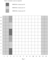
- the pattern in Fig. 1 can be used for configuration, and if the number of maximally supported ports exceeds 4, but does not exceed 8, the pattern in Fig. 2 can be used for configuration; and in configuration 2, if the number of maximally supported ports does not exceed 6, the pattern in Fig. 3 can be used for configuration; and if the number of maximally supported ports exceeds 6, but does not exceed 12, the pattern in Fig. 4 can be used for configuration.
- the number of ports described here refers to the total number of ports of all terminals multiplexed at each resource location.
- the first two columns represent control symbol fields, that is, symbol positions required for a downlink control channel; and the last two columns can be symbol positions required for an uplink control channel, that is, symbol resources of a data channel that cannot be used for a physical downlink shared channel (PDSCH).
- PDSCH physical downlink shared channel
- multiple transport receive points (TRPs)/antenna panels or sub-arrays may be considered for coordinated transmission.
- signals sent by different TRPs /panels may have relatively independent large-scale features, such as an average delay, delay spread, average Doppler shift, Doppler spread, and airspace reception parameter. Therefore, in NR, if large-scale parameters of two or more reference signal channels are consistent, it is called quasi-co-location (QCL). Otherwise, it is called non-QCL.
- the large-scale parameters are, for example, an average delay, delay spread, Doppler shift, Doppler spread, spatial reception parameter, average received power, and the like.
- the QCL is further explained as follows: the terminal cannot determine that received reference signal ports are from sites or antenna sub-arrays at same or different physical locations, and if parameters (or a subset thereof) such as the average delay, delay spread, Doppler shift, Doppler spread, spatial reception parameter, and average reception power of two reference signal ports are same, the two reference signals can be regarded as quasi-co-located in the sense of the aforementioned large-scale parameters.
- DMRS ports For DMRS ports, the concept of a QCL group is defined in an NR system, that is, a QCL group of DMRS ports (QCL group for short): DMRS ports in a QCL group are QCL, and DMRS ports in different QCL groups are not QCL. It is specified in the NR system that DMRS ports in a same code division multiplexing (CDM) group have a QCL relationship. That is, in a CDM group, reference signal ports occupy the same time-frequency resource, and are distinguished by orthogonal codewords.
- CDM code division multiplexing
- Each data channel can support two QCL groups.
- the data channel is, for example, a physical downlink shared channel (PDSCH).
- PDSCH physical downlink shared channel
- a QCL group of DMRS ports described in the embodiments of the present application may be referred to as a QCL group for short, and may also be referred to as a DMRS group.
- the DMRS port described in the embodiments of the present application may be referred to as a port for short, and may also be referred to as an antenna port.
- a specific scheme provided in an embodiment of the present application includes the following steps.
- Step I the network side indicates QCL group information (for indicating QCL grouping of DMRS ports) of DMRS ports through control signaling.
- the content of the QCL group information of the DMRS ports is optionally content as indicated in the following mode 1- 1, 1-2 or 1-3.
- CDM groups in a DMRS pattern are denoted by: CDM group 1, CDM group 2, ..., CDM group N.
- CDM group 1 CDM group 1
- CDM group 2 CDM group 2
- CDM group N CDM group N
- Mode 1-1 for example, notification can be made by DCI or MAC CE.
- An identifier corresponding to a reference signal having a QCL relationship with each CDM group (that is, a QCL reference source of each DMRS port in a CDM group n) in a DMRS pattern is respectively notified through control signaling.
- a reference signal having a QCL relationship with the CDM group n is Ref_n
- a corresponding identifier is ID_n; that is, only the ID_n needs to be notified
- the terminal can determine, according to the ID_n, that the reference signal having a QCL relationship with the CDM group n is Ref_n, and perform QCL grouping according to QCL reference sources; that is, DMRS ports included in CDM groups having the same identifier ID_n form a same QCL group, and the identifiers ID_n corresponding to DMRS ports of different QCL groups are different, and the identifiers ID_n corresponding to DMRS ports of a same QCL group are same.
- a set formed by DMRS ports included therein can be considered as one QCL group of DMRS ports. It should be noted that "one" here means that one group, but not one DMRS port, that is one QCL group, or DMRS group for short.
- Mode 1-2 CDM groups included in a QCL group i are directly indicated through control signaling, For example, for DMRS configuration type 2, the control signaling can indicate that QCL group 1 includes CDM groups 1 and 2, and QCL group 2 includes CDM group 3.
- Mode 1-3 A list of DMRS ports included in a QCL group i is directly indicated through control signaling. For example, for DMRS configuration type 2, if the number of data layers is 8, the control signaling can indicate that QCL group 1 includes DMRS ports 0, 1, 6, 7, and QCL group 2 includes DMRS ports 2, 3, 8, 9.
- control information i.e. QCL group information of DMRS ports
- QCL group information of DMRS ports can be notified to the terminal in a broadcast, multicast, or terminal-specific manner through radio resource control (RRC) configuration or media access control (MAC) control element (CE), or downlink control information (DCI).
- RRC radio resource control
- MAC media access control
- DCI downlink control information
- step I described above is not a step that must be performed, but an optional step; that is, the following steps can exist independently.
- the terminal can further determine an ordering manner of the DMRS ports occupied by the terminal, according to the QCL group information of the DMRS ports notified by the network side, in conjunction with a preset ordering rule of DMRS ports (the specific rule can be determined according to actual needs; exemplary description of some rules are provided in the following embodiments, but the present invention is not limited to the rules).
- Step II based on a number (i.e. a number of ranks) v of multiple-input multiple-output (MIMO) parallel transmission data layers, arranging the transmission data layers (each data layer is a data stream) into the following transmission signal vector according to serial numbers: x 0 i ⁇ x ⁇ ⁇ 1 i
- MIMO multiple-input multiple-output
- Y be a signal vector including v DMRS ports, where ports included in a set ⁇ P 0 ,..., P v-1 ⁇ are indicated by the DCI, and the ordering manner is determined by step III.
- Step III mapping one or more data layers to one or more DMRS ports used in transmission according to a preset DMRS port ordering rule, and performing transmission.
- Optional modes are as illustrated in the following modes 3-1, 3-2, 3-3, 3-4, 3-5.
- the above formula indicates that the corresponding elements in the vector are equal; that is, a data layer y ( p 0 ) ( i ) is mapped to a DMRS port x (0) ( i ) used in transmission, and similarly, a data layer y ( p v -1 ) ( i ) is mapped to a DMRS port x ( v -1) ( i ) used in transmission; the same formula is used similarly in the following mapping, which will not be described here.
- Case I is not part of the present invention and present for illustrative purpose only.
- Each DMRS port subset described in the embodiments of the present application is a set formed by DMRS ports included in each CDM group or QCL group.
- the v DMRS ports are arranged into a vector according to an ordering result described above: y p 0 i ⁇ y p ⁇ ⁇ 1 i
- the port subsets are further ordered; that is, subset 1 is arranged prior to subset 2, and the ports are in the order of 0, 1, 6, 7, 2, 3, 8, 9; as a result, P 0 , P 1 , P 2 , P 3 are equal to 0, 1, 6, 7, respectively, and P 4 , P 5 , P 6 , P 7 are equal to 2, 3, 8, 9, respectively.
- data layers 0, 1, 2, 3, 4, 5, 6, 7, 8 are mapped to DMRS ports 0, 1, 6, 7, 2, 3, 8, 9 used in transmission, respectively.
- Ordering within a port group according to the CDM group relationships of the DMRS ports in the DMRS pattern, the DMRS ports indicated in the DCI are ordered in the respective CDM groups to which the ports belong, where the serial numbers of the DMRS ports in each CDM group are arranged in ascending order (from small to large).
- the port subsets are further ordered in ascending order (from small to large) based on the smallest DMRS port serial number in each subset; that is, a subset in which the smallest DMRS port serial number is smaller is prior in the order, where each subset is DMRS ports in one CDM group.
- the v DMRS ports are arranged into a vector according to ordering described above: y p 0 i ⁇ y p ⁇ ⁇ 1 i
- the smallest DMRS port serial number in port subset 1 i.e. ports ⁇ 0, 1, 6, 7 ⁇
- the smallest DMRS port serial number in subset 2 i.e.
- the port subsets are further ordered; subset 1 is arranged prior to subset 2, and the ports are in the order of 0, 1, 6, 7, 2, 3, 8, 9; as a result, P 0 , P 1 , P 2 , P 3 are equal to 0, 1, 6, 7, respectively, and P 4 , P 5 , P 6 , P 7 are equal to 2, 3, 8, 9, respectively.
- data layers 0, 1, 2, 3, 4, 5, 6, 7, 8 are mapped to DMRS ports 0, 1, 6, 7, 2, 3, 8, 9 used in transmission, respectively.
- Ordering within a port group according to the CDM group relationships of the DMRS ports in the DMRS pattern, the DMRS ports indicated in the DCI are ordered in the respective CDM groups to which the ports belong, where the serial numbers of the DMRS ports in each group are arranged in ascending order (from small to large).
- Ordering between port groups the aforementioned subsets are arranged in ascending order based on the serial numbers of the CDM groups to which they belong.
- the v DMRS ports are arranged into a vector according to ordering described above: y p 0 i ⁇ y p ⁇ ⁇ 1 i .
- CDM group 1 including ports ⁇ 0, 1, 6, 7 ⁇ (ascending order)
- CDM group 2 including ports ⁇ 2, 3, 8, 9) (ascending order)
- the port subsets are further ordered (i.e. ⁇ CDM group 1, CDM group 2 ⁇ ), where subset 1 (i.e. ports ⁇ 0, 1, 6, 7 ⁇ ) is arranged prior to subset 2 (i.e.
- data layers 0, 1, 2, 3, 4, 5, 6, 7, 8 are mapped to DMRS ports 0, 1, 6, 7, 2, 3, 8, 9 used in transmission, respectively.
- Case I If there is only one QCL group or CDM group: the v DMRS ports allocated to the terminal in the DCI are ordered to ensure P 0 ⁇ P 1 ⁇ ,..., P v-1 . Case I is not part of the present invention and present for illustrative purpose only.
- the v DMRS ports are arranged into a vector according to ordering described above: y p 0 i ⁇ y p ⁇ ⁇ 1 i .
- port subset 1 includes 4 DMRS ports, which is greater than the number (3) of DMRS ports in subset 2, the port subsets are further ordered to obtain ⁇ subset 2, subset 1 ⁇ ; that is, P 0 , P 1 , P 2 are equal to 2, 3, 8, respectively, and P 3 , P 4 , P 5 , P 6 , P 7 are equal to 0, 1, 6, 7, respectively.
- the data layers 0, 1, 2, 3, 4, 5, 6, 7 are mapped to DMRS ports 2, 3, 8, 0, 1, 6, 7, respectively, used during transmission.
- the v DMRS ports are arranged into a vector according to ordering described above: y p 0 i ⁇ y p ⁇ ⁇ 1 i
- the data layers 0, 1, 2, 3, 4, 5, 6, 7 are mapped to DMRS ports 2, 3, 8, 0, 1, 6, 7, respectively, used during transmission.
- the preset DMRS port ordering rule described in the embodiments of the present application can be preset on the network side and the on the terminal side; that is, the same DMRS port ordering rule is set on both sides; and the same formula can be set on the network side and the terminal side, so as to map the data layers to the DMRS ports used in transmission in the same way.
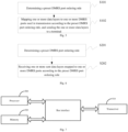
- a data sending method provided in an embodiment of the present application includes the following operations.
- a preset demodulation reference signal (DMRS) port ordering rule is determined; and a data layer is mapped to a DMRS port used in transmission according to the preset DMRS port ordering rule, and the data layer is sent to a terminal, so as to map a data layer to a DMRS port used in transmission according to a preset DMRS port ordering rule, and perform transmission.
- DMRS demodulation reference signal
- Mapping the one or more data layers to the one or more DMRS ports used in transmission according to the preset DMRS port ordering rule, and sending the one or more data layers to the terminal specifically includes:
- the method further includes: determining quasi-co-location (QCL) group information of the one or more DMRS ports; and notifying the terminal of the QCL group information.
- QCL quasi-co-location
- the signal vector formed by the v DMRS ports is determined according to an ordering result of the serial numbers of the v DMRS ports. Examples are case II in mode 3-1; case II in mode 3-4; and mode 3-2, mode 3-3, and mode 3-5.
- the ordering result is obtained by: ordering, within each subset, the serial numbers of DMRS ports in the DMRS port subset to obtain an ordering result, within each subset, of the DMRS port serial numbers corresponding to the DMRS port subset; and performing ordering between DMRS port subsets based on the ordering result, within each subset, of the DMRS port serial numbers corresponding to the DMRS port subset, where each DMRS port subset is a set formed by DMRS ports included in a CDM group or QCL group.
- Ordering between DMRS port subsets is performed by: performing ordering between DMRS port subsets based on the smallest DMRS port serial number in each DMRS port subset, such as in case II of mode 3-1 and mode 3-2 described above; or performing ordering between DMRS port subsets based on a serial number of the CDM group or QCL group corresponding to each DMRS port subset, such as in mode 3-3 described above; or performing ordering between DMRS port subsets based on the number of DMRS ports included in each DMRS port subset, such as in mode 3-5 described above.
- the QCL group information specifically includes one of the following information (that is, content described in the aforementioned mode 1-1, 1-2, or 1-3): in a DMRS pattern, an identifier corresponding to a reference signal having a QCL relationship with each code division multiplexing (CDM) group, where DMRS ports included in a CDM group having the same identifier form a same QCL group, and the identifiers corresponding to DMRS ports of different QCL groups are different, and the identifiers corresponding to DMRS ports of a same QCL group are same; a CDM group included in a QCL group; and a list of DMRS ports included in a QCL group.
- CDM code division multiplexing
- the QCL group information of the one or more DMRS ports is notified to the terminal in a broadcast, multicast or terminal-specific manner, through radio resource control (RRC) configuration or a media access control (MAC) control element (CE) or downlink control information (DCI).
- RRC radio resource control
- MAC media access control
- DCI downlink control information
- a data receiving method provided in an embodiment of the present application includes the following operations.
- Receiving one or more sent data layers mapped to one or more DMRS ports according to the preset DMRS port ordering rule specifically includes:
- the method further includes: receiving quasi-co-location (QCL) group information of the one or more DMRS ports notified by the network side.
- QCL quasi-co-location
- the terminal can further determine an ordering manner of the DMRS ports occupied by the terminal, according to the QCL group information of the DMRS ports, in conjunction with a preset ordering rule of DMRS port. Specifically, for example, content of ordering within a port group and ordering between port groups is involved in each of the aforementioned modes.
- the signal vector formed by the v DMRS ports is determined according to an ordering result of the serial numbers of the v DMRS ports.
- the ordering result is obtained by: ordering, within each subset, the serial numbers of DMRS ports in the DMRS port subset to obtain an ordering result, within each subset, of the DMRS port serial numbers corresponding to the DMRS port subset; and performing ordering between DMRS port subsets based on the ordering result, within each subset, of the DMRS port serial numbers corresponding to the DMRS port subset, where each DMRS port subset is a set formed by DMRS ports included in a CDM group or QCL group.
- Ordering between DMRS port subsets is performed by: performing ordering between DMRS port subsets based on the smallest DMRS port serial number in each DMRS port subset; or performing ordering between DMRS port subsets based on a serial number of the CDM group or QCL group corresponding to each DMRS port subset; or performing ordering between DMRS port subsets based on the number of DMRS ports included in each DMRS port subset.
- the QCL group information specifically includes one of the following information: in a DMRS pattern, an identifier corresponding to a reference signal having a QCL relationship with each code division multiplexing (CDM) group, where DMRS ports included in a CDM group having the same identifier form a same QCL group, and the identifiers corresponding to DMRS ports of different QCL groups are different, and the identifiers corresponding to DMRS ports of a same QCL group are same; a CDM group included in a QCL group; and a list of DMRS ports included in a QCL group.
- CDM code division multiplexing
- the notification is received in a broadcast, multicast, or terminal-specific manner, and the QCL group information of the one or more DMRS ports is acquired from radio resource control (RRC) configuration or a media access control (MAC) control element (CE) or downlink control information (DCI) in the notification.
- RRC radio resource control
- MAC media access control
- DCI downlink control information
- a data sending apparatus includes a memory 520 and a processor 500, where the memory 520 is configured to store program instructions, and the processor 500 is configured to call the program instructions stored in the memory 520, and execute the following steps according to obtained programs: determining a DMRS port ordering rule; and mapping one or more data layers to one or more DMRS ports used in transmission according to the preset DMRS port ordering rule, and sending the one or more data layers to a terminal through a transceiver 510.
- Embodiments illustrated in Fig. 7 are not part of the present invention and present for illustrative purpose only.
- a bus interface, the transceiver 510, and the like in Fig. 7 can all exist as optional devices in a data sending apparatus provided in the embodiment of the present application, and are not indispensable.
- the processor 500 mapping the one or more data layers to the one or more DMRS ports used in transmission according to the preset DMRS port ordering rule, and sending the one or more data layers to the terminal specifically includes:
- the processor 500 is further configured to: determine quasi-co-location (QCL) group information of the one or more DMRS ports; and notify the terminal of the QCL group information.
- QCL quasi-co-location
- the signal vector formed by the v DMRS ports is determined according to an ordering result of the serial numbers of the v DMRS ports.
- the ordering result is obtained by: ordering, within each subset, the serial numbers of DMRS ports in the DMRS port subset to obtain an ordering result, within each subset, of the DMRS port serial numbers corresponding to the DMRS port subset; and performing ordering between DMRS port subsets based on the ordering result, within each subset, of the DMRS port serial numbers corresponding to the DMRS port subset; where each DMRS port subset is a set formed by DMRS ports included in a CDM group or QCL group.
- ordering between DMRS port subsets is performed by: performing ordering between DMRS port subsets based on the smallest DMRS port serial number in each DMRS port subset; or performing ordering between DMRS port subsets based on a serial number of the CDM group or QCL group corresponding to each DMRS port subset; or performing ordering between DMRS port subsets based on the number of DMRS ports included in each DMRS port subset.
- the QCL group information specifically includes one of the following information: in a DMRS pattern, an identifier corresponding to a reference signal having a QCL relationship with each code division multiplexing (CDM) group, where DMRS ports included in a CDM group having the same identifier form a same QCL group, and the identifiers corresponding to DMRS ports of different QCL groups are different, and the identifiers corresponding to DMRS ports of a same QCL group are same; a CDM group included in a QCL group; and a list of DMRS ports included in a QCL group.
- CDM code division multiplexing
- the processor 500 notifies the QCL group information of the one or more DMRS ports to the terminal in a broadcast, multicast or terminal-specific manner, through radio resource control (RRC) configuration or a media access control (MAC) control element (CE) or downlink control information (DCI).
- RRC radio resource control
- MAC media access control
- DCI downlink control information
- the transceiver 510 is configured to receive and send data under the control of the processor 500.
- the bus architecture can include any number of interconnected buses and bridges, specifically linking together various circuits of one or more processors represented by the processor 500 and a memory represented by the memory 520.
- the bus architecture may also link together various other circuits of a peripheral device, a voltage stabilizer, a power management circuit and the like, which are all known in the art and thus not further described herein.
- a bus interface provides an interface.
- the transceiver 510 can be multiple elements, including a transmitter and a transceiver, providing a unit for communicating with various other apparatuses over a transmission medium.
- the processor 500 is responsible for managing the bus architecture and general processing, and the memory 520 can store data used by the processor 500 when the processor performs operations.
- the processor 500 can be a central processing unit (CPU), an application specific integrated circuit (ASIC), a field-programmable gate array (FPGA), or a complex programmable logic device (CPLD).
- CPU central processing unit
- ASIC application specific integrated circuit
- FPGA field-programmable gate array
- CPLD complex programmable logic device
- a data receiving apparatus provided in an embodiment of the present application includes a memory 620 and a processor 600, where the memory 620 is configured to store program instructions, and the processor 600 is configured to call the program instructions stored in the memory 620, and execute the following steps according to an obtained program: determining a preset DMRS port ordering rule; and receiving, by a transceiver 610, one or more sent data layers mapped to one or more DMRS ports according to the preset DMRS port ordering rule.
- Embodiments illustrated in Fig. 8 are not part of the present invention and present for illustrative purpose only.
- the devices other than the memory 620 and the processor 600 in Fig. 8 are optional devices that exist in a data receiving apparatus provided in the embodiment of the present application, and are not indispensable devices.
- receiving one or more sent data layers mapped to one or more DMRS ports according to the preset DMRS port ordering rule specifically includes:
- the processor 600 is further configured to receive quasi-co-located QCL group information of the one or more DMRS ports notified by the network side.
- the signal vector formed by the v DMRS ports is determined according to an ordering result of the serial numbers of the v DMRS ports.
- the ordering result is obtained by: ordering, within each subset, the serial numbers of DMRS ports in the DMRS port subset to obtain an ordering result, within each subset, of the DMRS port serial numbers corresponding to the DMRS port subset; and performing ordering between DMRS port subsets based on the ordering result, within each subset, of the DMRS port serial numbers corresponding to the DMRS port subset; where each DMRS port subset is a set formed by DMRS ports included in a CDM group or QCL group.
- the processor 600 performs ordering between DMRS port subsets by: performing ordering between DMRS port subsets based on the smallest DMRS port serial number in each DMRS port subset; or performing ordering between DMRS port subsets based on a serial number of the CDM group or QCL group corresponding to each DMRS port subset; or performing ordering between DMRS port subsets based on the number of DMRS ports included in each DMRS port subset.
- the QCL group information specifically includes one of the following information: in a DMRS pattern, an identifier corresponding to a reference signal having a QCL relationship with each code division multiplexing (CDM) group, where DMRS ports included in a CDM group having the same identifier form a same QCL group, and the identifiers corresponding to DMRS ports of different QCL groups are different, and the identifiers corresponding to DMRS ports of a same QCL group are same; a CDM group included in a QCL group; and a list of DMRS ports included in a QCL group.
- CDM code division multiplexing
- the processor 600 receives the notification in a broadcast, multicast, or terminal-specific manner, and acquires the QCL group information of the one or more DMRS ports from radio resource control (RRC) configuration or a media access control (MAC) control element (CE) or downlink control information (DCI) in the notification.
- RRC radio resource control
- MAC media access control
- DCI downlink control information
- the transceiver 610 is configured to receive and send data under the control of the processor 600.
- the bus architecture can include any number of interconnected buses and bridges, specifically linking together various circuitries of one or more processors represented by the processor 600 and a memory represented by the memory 620.
- the bus architecture may also link together various other circuitry of a peripheral device, a voltage stabilizer, a power management circuit and the like, which are all known in the art and thus not further described herein.
- a bus interface provides an interface.
- the transceiver 610 can be multiple elements, including a transmitter and a receiver, providing a unit for communicating with various other apparatuses over a transmission medium.
- a user interface 630 may also be an interface capable of externally or internally connecting a required device, including but not limited to a keypad, a display, a speaker, a microphone, a joystick, or the like.
- the processor 600 is responsible for managing the bus architecture and general processing, and the memory 620 may store data used by the processor 600 when the processor performs operations.
- the processor 600 can be a CPU (Central Processing Unit), an ASIC (Application Specific Integrated Circuit), an FPGA (Field-Programmable Gate Array) or a CPLD (Complex Programmable Logic Device).
- CPU Central Processing Unit
- ASIC Application Specific Integrated Circuit
- FPGA Field-Programmable Gate Array
- CPLD Complex Programmable Logic Device
- another data sending apparatus includes: a determining unit 11 configured to determine a preset demodulation reference signal (DMRS) port ordering rule; and a sending unit 12 configured to map one or more data layers to one or more DMRS ports used in transmission according to the preset DMRS port ordering rule, and send the one or more data layers to a terminal.
- DMRS demodulation reference signal
- another data receiving apparatus includes: a determining unit 21 configured to determine a preset DMRS port ordering rule; and a receiving unit 22 configured to receive one or more sent data layer mapped to one or more DMRS ports according to the preset DMRS port ordering rule.
- An embodiment of the present application provides a computer storage medium configured to store computer program instructions for the aforementioned computing device, including a program for executing the aforementioned information indicating or determining method.
- Embodiments of the computer storage medium are not part of the present invention and present for illustrative purpose only.
- the computer storage medium may be any available medium or data storage device that can be accessed by a computer, including but not limited to a magnetic memory (such as a floppy disk, hard disk, magnetic tape, magneto-optical disk (MO), etc.), an optical memory (such as a CD, DVD, BD, HVD, etc.), and a semiconductor memory (such as an ROM, EPROM, EEPROM, non-volatile memory (NAND Flash), and a solid-state drive (SSD)).
- a magnetic memory such as a floppy disk, hard disk, magnetic tape, magneto-optical disk (MO), etc.
- an optical memory such as a CD, DVD, BD, HVD, etc.
- semiconductor memory such as an ROM, EPROM, EEPROM, non-volatile memory (NAND Flash), and a solid-state drive (SSD)
- the method provided in the embodiment of the present application may be applied to a terminal device, and may also be applied to a network device.
- the terminal device may also be called user equipment ("UE"), mobile station ("MS”), mobile terminal, etc.
- the terminal can have the ability to communicate with one or more core networks through a radio access network (RAN).
- RAN radio access network
- the terminal may be a mobile phone (or a "cellular" phone), or a computer with a mobile property.
- the terminal may also be a portable, pocket-sized, handheld, computer-built or vehicle-mounted mobile apparatus.
- the network device can be a base station (e.g. an access point), which is a device, in an access network, that communicates with a wireless terminal through one or more sectors at an air interface.
- the base station can be used to perform conversion between a received air frame and IP packet as a router between the wireless terminal and the rest of the access network, where the rest of the access network can include an Internet Protocol (IP) network.
- IP Internet Protocol
- the base station may also coordinate attribute management of the air interface.
- the base station may be a base transceiver station (BTS) in GSM or CDMA, or may be a base station (NodeB) in WCDMA, or may also be an evolved base station (eNodeB or eNB or e-NodeB, evolutional Node B) in LTE, but the embodiments of the present invention are not limited thereto.
- BTS base transceiver station
- NodeB base station
- eNodeB or eNB or e-NodeB, evolutional Node B evolutional Node B
- LTE long term evolutional Node B
- the present application is described with reference to the flow diagrams and/or block diagrams of the method, device (system) and computer program product according to the embodiments of the present invention. It should be understood that each process and/or block in the flow diagrams and/or block diagrams, as well as combinations of processes and/or blocks in the flow diagrams and/or block diagrams can be implemented by computer program instructions.
- the computer program instructions can be provided to a processor of a general purpose computer, a special purpose computer, an embedded processor or other programmable data processing device to produce a machine, so that the instructions processed by the processor of the computer or other programmable data processing device generates a device for achieving functions specified in one or more processes of the flow diagrams and/or one or more blocks of the block diagrams.
- the computer program instructions may also be stored in a computer readable memory that can instruct a computer or other programmable data processing device to operate in a specified manner, so that the instructions stored in the computer readable memory generates a manufactured product containing an instruction device, where the instruction device achieves the functions specified in one or more processes of the flow diagrams and/or one or more blocks of the block diagrams.
- the computer program instructions may also be loaded to a computer or other programmable data processing device, so that a series of operation steps are executed on the computer or other programmable data processing device to generate computer implemented processing, so that the instructions executed on the computer or other programmable data processing device provide steps for achieving functions specified in one or more processes of the flow diagrams and/or one or more blocks of the block diagrams.
Landscapes
- Engineering & Computer Science (AREA)
- Signal Processing (AREA)
- Computer Networks & Wireless Communication (AREA)
- Physics & Mathematics (AREA)
- Mathematical Physics (AREA)
- Quality & Reliability (AREA)
- Electromagnetism (AREA)
- Mobile Radio Communication Systems (AREA)
Claims (8)
- Datenübertragungsverfahren, umfassend:Ermitteln (S101) einer voreingestellten Anschlussordnungsregel eines Demodulationsreferenzsignals, DMRS; undZuordnen (S102) einer oder mehrerer Datenschichten zu einem oder mehreren DMRS-Anschlüssen, die bei einer Übertragung gemäß der voreingestellten DMRS-Anschlussordnungsregel verwendet werden, und Senden der einen oder mehreren Datenschichten zu einem Endgerät;wobei das Zuordnen (S102) der einen oder mehreren Datenschichten zu dem einen oder den mehreren DMRS Anschlüssen, die bei einer Übertragung gemäß der voreingestellten DMRS-Anschlussordnungsregel verwendet wird, und das Senden der einen oder mehreren Datenschichten zu dem Endgerät, insbesondere umfassen: basierend auf einer Anzahl v von parallelen Übertragungsdatenschichten mit mehreren Eingängen und mehreren Ausgängen (Multiple-Input Multiple-Output, MIMO), Anordnen der einen oder mehreren Datenschichten gemäß den Seriennummern in einen folgenden Übertragungssignalvektor:
 Ermitteln eines folgenden Signalvektors, der durch eine Anzahl v von DMRS-Anschlüssen gebildet wird:
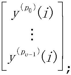 Zuordnen der Anzahl v von Datenschichten zu der Anzahl v von DMRS-Anschlüssen gemäß einer folgenden Formel und Senden der Anzahl v von Datenschichten zu dem Endgerät:
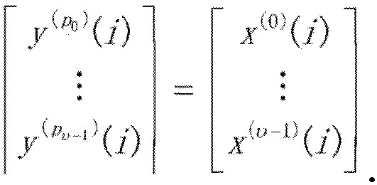 wobei
wobei

0 )(i) zugeordnet wird, der bei einer Übertragung verwendet wird, ..., eine Datenschicht x (v-1)(i) einem DMRS-Anschluss y (pv-1 )(i) zugeordnet wird, der bei einer Übertragung verwendet wird;wobei das Verfahren ferner umfasst:Ermitteln von Gruppeninformationen einer Quasi-Kolokation (Quasi-Co-Location group information, QCL-Gruppeninformationen) des einen oder der mehreren DMRS-Anschlüsse; undBenachrichtigen des Endgeräts über die QCL-Gruppeninformationen;wobei, wenn eine Vielzahl von QCL-Gruppen oder CDM-Gruppen vorhanden ist, der Signalvektor durch die Anzahl v von DMRS-Anschlüssen gemäß einem Ordnungsergebnis für die Seriennummern der Anzahl v von DMRS-Anschlüssen ermittelt wird;wobei das Ordnungsergebnis erhalten wird durch:Ordnen der Seriennummern der DMRS-Anschlüsse in jeder DMRS-Anschlussteilgruppe, um ein Ordnungsergebnis der Seriennummern der DMRS-Anschlüsse zu erhalten, die jeder DMRS-Anschlussteilgruppe entsprechen; undDurchführen eines Ordnens zwischen den DMRS-Anschlussteilgruppen basierend auf dem Ordnungsergebnis der Seriennummern der DMRS-Anschlüsse, die jeder DMRS-Anschlussteilgruppe entsprechen;wobei jede DMRS-Anschlussteilgruppe ein Satz ist, der durch DMRS-Anschlüsse gebildet wird, die in einer CDM-Gruppe oder einer QCL-Gruppe enthalten sind;wobei das Ordnen zwischen den DMRS-Anschlussteilgruppen durchgeführt wird durch:Durchführen eines Ordnens zwischen den DMRS-Anschlussteilgruppen basierend auf einer Reihenfolge von einer kleineren zu einer größeren Anzahl von DMRS-Anschlüssen, die in jeder DMRS-Anschlussteilgruppe enthalten sind; oderDurchführen eines Ordnens zwischen den DMRS-Anschlussteilgruppen basierend auf einer Reihenfolge von einer größeren zu einer kleineren Anzahl von DMRS-Anschlüssen, die in jeder DMRS-Anschlussteilgruppe enthalten sind. - Verfahren nach Anspruch 1, wobei die QCL-Gruppeninformationen insbesondere eine der folgenden Informationen umfassen:in einem DMRS-Muster, eine Kennung, die einem Referenzsignal entspricht, das eine QCL-Beziehung mit jeder Codemultiplexgruppe (Code Division Multiplexing group, CDM-Gruppe) aufweist, wobei die DMRS-Anschlüsse, die in den CDM-Gruppen enthalten sind, welche die gleiche Kennung aufweisen, eine gleiche QCL-Gruppe bilden, und wobei Kennungen, die DMRS-Anschlüssen aus unterschiedlichen QCL-Gruppen entsprechen, unterschiedlich sind, und wobei Kennungen, die DMRS-Anschlüssen aus der gleichen QCL-Gruppe entsprechen, gleich sind;wobei eine CDM-Gruppe in einer QCL-Gruppe enthalten ist; undwobei eine Liste von DMRS-Anschlüssen in einer QCL-Gruppe enthalten ist.
- Verfahren nach Anspruch 1, wobei die QCL-Gruppeninformationen des einen oder der mehreren DMRS-Anschlüsse dem Endgerät in einem Broadcast, einem Multicast oder einer endgerätespezifischen Weise, durch eine Konfiguration einer Funkressourcensteuerung (Radio Resource Control configuration, RRC-Konfiguration) oder ein Steuerelement (Control Element, CE) einer Medienzugangssteuerung (Media access control, MAC) oder Downlink-Steuerinformationen (Downlink Control Information, DCI) mitgeteilt werden.
- Datenempfangsverfahren, umfassend:Ermitteln (S201) einer voreingestellten Anschlussordnungsregel eines Demodulationsreferenzsignals, DMRS; undEmpfangen (S202) einer oder mehrerer übertragener Datenschichten, die gemäß der voreingestellten DMRS-Anschlussordnungsregel dem einen oder den mehreren DMRS-Anschlüssen zugeordnet sind;wobei das Empfangen (S202) einer oder mehrerer übertragener Datenschichten, die gemäß der voreingestellten DMRS-Anschlussordnungsregel dem einen oder den mehreren DMRS-Anschlüssen zugeordnet sind,insbesondere umfasst:basierend auf einer Anzahl v von parallelen Übertragungsdatenschichten mit mehreren Eingängen und mehreren Ausgängen (Multiple-Input Multiple-Output, MIMO), Anordnen der einen oder mehreren Datenschichten gemäß den Seriennummern in einen folgenden Übertraunssinalvektor:
 Ermitteln eines folgenden Signalvektors, der durch eine Anzahl v von DMRS-Anschlüssen gebildet wird:
 Empfangen der einen oder mehreren übertragenen Datenschichten, die dem einen oder den mehreren DMRS-Anschlüssen, die bei einer Übertragung verwendet werden, zugeordnet sind, gemäß einer folgenden Formel:
 wobei
wobei

0 )(i) zugeordnet wird, der bei einer Übertragung verwendet wird, ..., eine Datenschicht x(v-1)(i) einem DMRS-Anschluss y (pv-1 )(i) zugeordnet wird, der bei einer Übertragung verwendet wird;wobei das Verfahren ferner umfasst:Empfangen von Gruppeninformationen einer Quasi-Kolokation (Quasi-Co-Location group information, QCL-Gruppeninformationen) des einen oder der mehreren DMRS-Anschlüsse, die von einer Netzwerkseite mitgeteilt wurden;wobei, wenn eine Vielzahl von QCL-Gruppen oder CDM-Gruppen vorhanden ist, der Signalvektor durch die Anzahl v von DMRS-Anschlüssen gemäß einem Ordnungsergebnis für die Seriennummern der Anzahl v von DMRS-Anschlüssen ermittelt wird;wobei das Ordnungsergebnis erhalten wird durch:Ordnen der Seriennummern der DMRS-Anschlüsse in jeder DMRS-Anschlussteilgruppe, um ein Ordnungsergebnis der Seriennummern der DMRS-Anschlüsse zu erhalten, die jeder DMRS-Anschlussteilgruppe entsprechen; undDurchführen eines Ordnens zwischen den DMRS-Anschlussteilgruppen basierend auf dem Ordnungsergebnis der Seriennummern der DMRS-Anschlüsse, die jeder DMRS-Anschlussteilgruppe entsprechen;wobei jede DMRS-Anschlussteilgruppe ein Satz ist, der durch DMRS-Anschlüsse gebildet wird, die in einer CDM-Gruppe oder einer QCL-Gruppe enthalten sind;wobei das Ordnen zwischen den DMRS-Anschlussteilgruppen durchgeführt wird durch:Durchführen eines Ordnens zwischen den DMRS-Anschlussteilgruppen basierend auf einer Reihenfolge von einer kleineren zu einer größeren Anzahl von DMRS-Anschlüssen, die in jeder DMRS-Anschlussteilgruppe enthalten sind; oderDurchführen eines Ordnens zwischen den DMRS-Anschlussteilgruppen basierend auf einer Reihenfolge von einer größeren zu einer kleineren Anzahl von DMRS-Anschlüssen, die in jeder DMRS-Anschlussteilgruppe enthalten sind. - Verfahrens nach Anspruch 4, wobei die Mitteilung in einem Broadcast, einem Multicast oder einer endgerätespezifischen Weise empfangen wird, und wobei die QCL-Gruppeninformationen des einen oder der mehreren DMRS-Anschlüsse von einer Konfiguration einer Funkressourcensteuerung (Radio Resource Control configuration, RRC-Konfiguration) oder einem Steuerelement (Control Element, CE) einer Medienzugangssteuerung (Media access control, MAC) oder von Downlink-Steuerinformationen (Downlink Control Information, DCI) in der Mitteilung erfasst werden.
- Verfahren nach Anspruch 5, wobei die QCL-Gruppeninformationen insbesondere eine der folgenden Informationen umfassen:in einem DMRS-Muster, eine Kennung, die einem Referenzsignal entspricht, das eine QCL-Beziehung mit jeder Codemultiplexgruppe (Code Division Multiplexing group, CDM-Gruppe) aufweist, wobei die DMRS-Anschlüsse, die in einer CDM-Gruppe enthalten sind, welche die gleiche Kennung aufweisen, eine gleiche QCL-Gruppe bilden, und wobei Kennungen, die DMRS-Anschlüssen aus unterschiedlichen QCL-Gruppen entsprechen, unterschiedlich sind, und wobei Kennungen, die DMRS-Anschlüssen aus der gleichen QCL-Gruppe entsprechen, gleich sind;wobei eine CDM-Gruppe in einer QCL-Gruppe enthalten ist; undwobei eine Liste von DMRS-Anschlüssen in einer QCL-Gruppe enthalten ist.
- Datensendevorrichtung, umfassend:eine Ermittlungseinheit (11), die konfiguriert ist zum Ermitteln einer voreingestellten Anschlussordnungsregel eines Demodulationsreferenzsignals, DMRS; undeine Sendeeinheit (12), die konfiguriert ist zum Zuordnen einer oder mehrerer Datenschichten zu einem oder mehreren DMRS-Anschlüssen, die bei einer Übertragung gemäß der voreingestellten DMRS-Anschlussordnungsregel verwendet werden, und zum Senden der einen oder mehreren Datenschichten zu einem Endgerät;wobei die Sendeeinheit (12) ferner konfiguriert ist zum: basierend auf einer Anzahl v von parallelen Übertragungsdatenschichten mit mehreren Eingängen und mehreren Ausgängen (Multiple-Input Multiple-Output, MIMO), Anordnen der einen oder mehreren Datenschichten gemäß den Seriennummern in einen folgenden Übertragungssignalvektor:
 Ermitteln eines folgenden Signalvektors, der durch eine Anzahl v von DMRS-Anschlüssen gebildet wird:
 Zuordnen der Anzahl v von Datenschichten zu der Anzahl v von DMRS-Anschlüssen gemäß einer folgenden Formel und Senden der Anzahl v von Datenschichten zu dem Endgerät:
 wobei
wobei

0 )(i) zugeordnet wird, der bei einer Übertragung verwendet wird, ..., eine Datenschicht x (v-1)(i) einem DMRS-Anschluss y (pv-1 ) (i) zugeordnet wird, der bei einer Übertragung verwendet wird;wobei die Ermittlungseinheit (11) ferner konfiguriert ist zum Ermitteln von Gruppeninformationen einer Quasi-Kolokation (Quasi-Co-Location group information, QCL-Gruppeninformationen) des einen oder der mehreren DMRS-Anschlüsse; undwobei die Sendeeinheit (12) ferner konfiguriert ist zum Benachrichtigen des Endgeräts über die QCL-Gruppeninformationen;wobei, wenn eine Vielzahl von QCL-Gruppen oder CDM-Gruppen vorhanden ist, der Signalvektor durch die Anzahl v von DMRS-Anschlüssen gemäß einem Ordnungsergebnis für die Seriennummern der Anzahl v von DMRS-Anschlüssen ermittelt wird;wobei das Ordnungsergebnis erhalten wird durch:Ordnen der Seriennummern der DMRS-Anschlüsse in jeder DMRS-Anschlussteilgruppe, um ein Ordnungsergebnis der Seriennummern der DMRS-Anschlüsse zu erhalten, die jeder DMRS-Anschlussteilgruppe entsprechen; undDurchführen eines Ordnens zwischen den DMRS-Anschlussteilgruppen basierend auf dem Ordnungsergebnis der Seriennummern der DMRS-Anschlüsse, die jeder DMRS-Anschlussteilgruppe entsprechen;wobei jede DMRS-Anschlussteilgruppe ein Satz ist, der durch DMRS-Anschlüsse gebildet wird, die in einer CDM-Gruppe oder einer QCL-Gruppe enthalten sind;wobei das Ordnen zwischen den DMRS-Anschlussteilgruppen durchgeführt wird durch:Durchführen eines Ordnens zwischen den DMRS-Anschlussteilgruppen basierend auf einer Reihenfolge von einer kleineren zu einer größeren Anzahl von DMRS-Anschlüssen, die in jeder DMRS-Anschlussteilgruppe enthalten sind; oderDurchführen eines Ordnens zwischen den DMRS-Anschlussteilgruppen basierend auf einer Reihenfolge von einer größeren zu einer kleineren Anzahl von DMRS-Anschlüssen, die in jeder DMRS-Anschlussteilgruppe enthalten sind. - Datenempfangsvorrichtung, umfassend:eine Ermittlungseinheit (21), die konfiguriert ist zum Ermitteln einer voreingestellten Anschlussordnungsregel eines Demodulationsreferenzsignals, DMRS; undeine Empfangseinheit (22), die konfiguriert ist zum Empfangen einer oder mehrerer gesendeter Datenschichten, die gemäß der voreingestellten DMRS-Anschlussordnungsregel dem einen oder den mehreren DMRS-Anschlüssen zugeordnet sind;wobei die Empfangseinheit (22) ferner konfiguriert ist zum:basierend auf einer Anzahl v von parallelen Übertragungsdatenschichten mit mehreren Eingängen und mehreren Ausgängen (Multiple-Input Multiple-Output, MIMO), Anordnen der einen oder mehreren Datenschichten gemäß den Seriennummern in einen folgenden Übertragungssignalvektor:
 Ermitteln eines folgenden Signalvektors, der durch eine Anzahl v von DMRS-Anschlüssen gebildet wird:
 Empfangen der einen oder mehreren übertragenen Datenschichten, die dem einen oder den mehreren DMRS-Anschlüssen, die bei einer Übertragung verwendet werden, zugeordnet sind, gemäß einer folgenden Formel:
 wobei
wobei

0 )(i) zugeordnet wird, der bei einer Übertragung verwendet wird, ..., eine Datenschicht x (v-1)(i) einem DMRS-Anschluss y (pv-1 )(i) zugeordnet wird, der bei einer Übertragung verwendet wird;wobei die Empfangseinheit (22) ferner konfiguriert ist zum Empfangen von Gruppeninformationen einer Quasi-Kolokation (Quasi-Co-Location group information, QCL-Gruppeninformationen) des einen oder der mehreren DMRS-Anschlüsse, die von einer Netzwerkseite mitgeteilt wurden;wobei, wenn eine Vielzahl von QCL-Gruppen oder CDM-Gruppen vorhanden ist, der Signalvektor durch die Anzahl v von DMRS-Anschlüssen gemäß einem Ordnungsergebnis für die Seriennummern der Anzahl v von DMRS-Anschlüssen ermittelt wird;wobei das Ordnungsergebnis erhalten wird durch:Ordnen der Seriennummern der DMRS-Anschlüsse in jeder DMRS-Anschlussteilgruppe, um ein Ordnungsergebnis der Seriennummern der DMRS-Anschlüsse zu erhalten, die jeder DMRS-Anschlussteilgruppe entsprechen; undDurchführen eines Ordnens zwischen den DMRS-Anschlussteilgruppen basierend auf dem Ordnungsergebnis der Seriennummern der DMRS-Anschlüsse, die jeder DMRS-Anschlussteilgruppe entsprechen;wobei jede DMRS-Anschlussteilgruppe ein Satz ist, der durch DMRS-Anschlüsse gebildet wird, die in einer CDM-Gruppe oder einer QCL-Gruppe enthalten sind;wobei das Ordnen zwischen den DMRS-Anschlussteilgruppen durchgeführt wird durch:Durchführen eines Ordnens zwischen den DMRS-Anschlussteilgruppen basierend auf einer Reihenfolge von einer kleineren zu einer größeren Anzahl von DMRS-Anschlüssen, die in jeder DMRS-Anschlussteilgruppe enthalten sind; oderDurchführen eines Ordnens zwischen den DMRS-Anschlussteilgruppen basierend auf einer Reihenfolge von einer größeren zu einer kleineren Anzahl von DMRS-Anschlüssen, die in jeder DMRS-Anschlussteilgruppe enthalten sind.
Applications Claiming Priority (2)
| Application Number | Priority Date | Filing Date | Title |
|---|---|---|---|
| CN201711192554.6A CN109842468B (zh) | 2017-11-24 | 2017-11-24 | 数据传输方法及装置、计算机存储介质 |
| PCT/CN2018/109895 WO2019100859A1 (zh) | 2017-11-24 | 2018-10-11 | 数据传输方法及装置、计算机存储介质 |
Publications (3)
| Publication Number | Publication Date |
|---|---|
| EP3716708A1 EP3716708A1 (de) | 2020-09-30 |
| EP3716708A4 EP3716708A4 (de) | 2021-01-13 |
| EP3716708B1 true EP3716708B1 (de) | 2025-01-08 |
Family
ID=66631798
Family Applications (1)
| Application Number | Title | Priority Date | Filing Date |
|---|---|---|---|
| EP18882179.7A Active EP3716708B1 (de) | 2017-11-24 | 2018-10-11 | Datenübertragungsverfahren sowie vorrichtung und computerspeichermedium |
Country Status (6)
| Country | Link |
|---|---|
| US (1) | US11528120B2 (de) |
| EP (1) | EP3716708B1 (de) |
| JP (1) | JP2021505022A (de) |
| KR (1) | KR20200088455A (de) |
| CN (1) | CN109842468B (de) |
| WO (1) | WO2019100859A1 (de) |
Families Citing this family (8)
| Publication number | Priority date | Publication date | Assignee | Title |
|---|---|---|---|---|
| CN110463128B (zh) * | 2017-03-24 | 2022-10-18 | 苹果公司 | 用于CoMP的DM-RS分组和CSI报告 |
| CN110034890B (zh) * | 2018-01-12 | 2020-07-10 | 电信科学技术研究院有限公司 | 数据传输方法及装置、计算机存储介质 |
| CN111435883B (zh) * | 2019-01-11 | 2021-10-26 | 华为技术有限公司 | 准共址指示方法及装置 |
| US11240836B2 (en) * | 2019-08-08 | 2022-02-01 | Qualcomm Incorproated | Multi-state reference signaling and single-state data techniques |
| KR20240027614A (ko) * | 2021-07-20 | 2024-03-04 | 엘지전자 주식회사 | 무선 통신 시스템에서 상향링크 또는 하향링크 송수신을 수행하는 방법 및 장치 |
| US20250015942A1 (en) * | 2022-01-26 | 2025-01-09 | Qualcomm Incorporated | Downlink scheduling for increased orthogonal dmrs ports and prb bundling size |
| CN117413618A (zh) * | 2022-01-28 | 2024-01-16 | 中兴通讯股份有限公司 | 用于dmrs端口配置和指示的系统和方法 |
| US20240322969A1 (en) * | 2023-03-24 | 2024-09-26 | Samsung Electronics Co., Ltd. | Apparatus and methods for indicating dmrs ports for user equipment in a wireless communication system |
Citations (1)
| Publication number | Priority date | Publication date | Assignee | Title |
|---|---|---|---|---|
| US20190052502A1 (en) * | 2016-04-22 | 2019-02-14 | Huawei Technologies Co., Ltd. | Data transmission method, user equipment, and network side device |
Family Cites Families (12)
| Publication number | Priority date | Publication date | Assignee | Title |
|---|---|---|---|---|
| WO2011085509A1 (en) | 2010-01-12 | 2011-07-21 | Telefonaktiebolaget L M Ericsson (Publ) | Layer-to dm rs port mapping for lte-advanced |
| KR101740221B1 (ko) * | 2010-01-18 | 2017-05-29 | 주식회사 골드피크이노베이션즈 | 채널상태정보-기준신호 할당 방법 및 장치 |
| KR101789621B1 (ko) * | 2010-01-19 | 2017-10-25 | 엘지전자 주식회사 | 하향링크 데이터 전송방법 및 기지국과, 하향링크 데이터 수신방법 및 사용자기기 |
| CA2790291C (en) * | 2010-01-20 | 2017-08-15 | Telefonaktiebolaget L M Ericsson (Publ) | Antenna port mapping method and device for demodulation reference signals |
| CN102158319B (zh) * | 2010-02-12 | 2015-12-16 | 中兴通讯股份有限公司 | 一种基于混合复用解调参考符号的预编码方法及装置 |
| CN102299769B (zh) * | 2011-09-01 | 2014-06-25 | 电信科学技术研究院 | 一种下行控制信息传输方法及装置 |
| EP3232598B1 (de) * | 2012-03-12 | 2019-09-18 | Samsung Electronics Co., Ltd. | Verfahren und vorrichtung zum senden/empfangen eines steuerkanals in einem drahtloskommunikationssystem |
| CN104079384B (zh) | 2013-03-27 | 2017-10-17 | 华为技术有限公司 | 多天线系统的数据传输方法和设备 |
| CN104579595A (zh) * | 2013-10-16 | 2015-04-29 | 中兴通讯股份有限公司 | ePHICH的发送和接收方法及系统 |
| CN107078874B (zh) * | 2014-09-24 | 2020-09-04 | Lg 电子株式会社 | 无线通信系统中发送和接收参考信号的方法及其装置 |
| CN106712915B (zh) * | 2015-11-16 | 2020-06-30 | 中国移动通信集团公司 | 一种发送解调参考信号的方法、装置、基站及终端 |
| CN107889258B (zh) * | 2016-09-30 | 2020-07-24 | 华为技术有限公司 | 获取、下发dmrs端口配置信息的方法和装置 |
-
2017
- 2017-11-24 CN CN201711192554.6A patent/CN109842468B/zh active Active
-
2018
- 2018-10-11 US US16/766,700 patent/US11528120B2/en active Active
- 2018-10-11 EP EP18882179.7A patent/EP3716708B1/de active Active
- 2018-10-11 WO PCT/CN2018/109895 patent/WO2019100859A1/zh not_active Ceased
- 2018-10-11 KR KR1020207018236A patent/KR20200088455A/ko not_active Ceased
- 2018-10-11 JP JP2020528299A patent/JP2021505022A/ja active Pending
Patent Citations (1)
| Publication number | Priority date | Publication date | Assignee | Title |
|---|---|---|---|---|
| US20190052502A1 (en) * | 2016-04-22 | 2019-02-14 | Huawei Technologies Co., Ltd. | Data transmission method, user equipment, and network side device |
Also Published As
| Publication number | Publication date |
|---|---|
| US20200287699A1 (en) | 2020-09-10 |
| CN109842468A (zh) | 2019-06-04 |
| WO2019100859A1 (zh) | 2019-05-31 |
| EP3716708A1 (de) | 2020-09-30 |
| JP2021505022A (ja) | 2021-02-15 |
| EP3716708A4 (de) | 2021-01-13 |
| US11528120B2 (en) | 2022-12-13 |
| CN109842468B (zh) | 2020-09-01 |
| KR20200088455A (ko) | 2020-07-22 |
Similar Documents
| Publication | Publication Date | Title |
|---|---|---|
| US20230246754A1 (en) | Method for indicating reference signal configuration information, base station, and terminal | |
| US12368559B2 (en) | Technique for configuring a phase tracking reference signal | |
| EP3716708B1 (de) | Datenübertragungsverfahren sowie vorrichtung und computerspeichermedium | |
| US10863367B2 (en) | Reference signal sequence configuration method and network device | |
| JP7030202B2 (ja) | リソース指示方法、端末デバイス、及びネットワークデバイス | |
| EP2882244B1 (de) | Basisstation, endgerät, kommunikationssystem, kommunikationsverfahren und integrierte schaltung | |
| CN110226306A (zh) | 共享频谱的广播控制信道 | |
| EP3526907A1 (de) | Verfahren zur anpassung der dichte von demodulationsreferenzsignalen | |
| AU2013282265A1 (en) | Uplink hybrid acknowledgement signaling in wireless communications systems | |
| CN104205970A (zh) | 基站、终端、通信系统、通信方法以及集成电路 | |
| KR20190053748A (ko) | 무선 통신 시스템에서 제어 정보를 송수신하는 방법 및 장치 | |
| EP3739792B1 (de) | Datenübertragungsverfahren sowie vorrichtung und computerspeichermedium | |
| CN109842469B (zh) | 信息指示、确定方法及装置、计算机存储介质 | |
| CN119096639A (zh) | 用于多天线面板物理上行链路控制信道发送的控制信令 |
Legal Events
| Date | Code | Title | Description |
|---|---|---|---|
| STAA | Information on the status of an ep patent application or granted ep patent |
Free format text: STATUS: THE INTERNATIONAL PUBLICATION HAS BEEN MADE |
|
| PUAI | Public reference made under article 153(3) epc to a published international application that has entered the european phase |
Free format text: ORIGINAL CODE: 0009012 |
|
| STAA | Information on the status of an ep patent application or granted ep patent |
Free format text: STATUS: REQUEST FOR EXAMINATION WAS MADE |
|
| 17P | Request for examination filed |
Effective date: 20200604 |
|
| AK | Designated contracting states |
Kind code of ref document: A1 Designated state(s): AL AT BE BG CH CY CZ DE DK EE ES FI FR GB GR HR HU IE IS IT LI LT LU LV MC MK MT NL NO PL PT RO RS SE SI SK SM TR |
|
| AX | Request for extension of the european patent |
Extension state: BA ME |
|
| A4 | Supplementary search report drawn up and despatched |
Effective date: 20201211 |
|
| RIC1 | Information provided on ipc code assigned before grant |
Ipc: H04W 72/04 20090101AFI20201207BHEP Ipc: H04L 1/18 20060101ALI20201207BHEP Ipc: H04L 5/00 20060101ALI20201207BHEP |
|
| DAV | Request for validation of the european patent (deleted) | ||
| DAX | Request for extension of the european patent (deleted) | ||
| RAP1 | Party data changed (applicant data changed or rights of an application transferred) |
Owner name: DATANG MOBILE COMMUNICATIONS EQUIPMENT CO., LTD. |
|
| STAA | Information on the status of an ep patent application or granted ep patent |
Free format text: STATUS: EXAMINATION IS IN PROGRESS |
|
| 17Q | First examination report despatched |
Effective date: 20221219 |
|
| GRAP | Despatch of communication of intention to grant a patent |
Free format text: ORIGINAL CODE: EPIDOSNIGR1 |
|
| STAA | Information on the status of an ep patent application or granted ep patent |
Free format text: STATUS: GRANT OF PATENT IS INTENDED |
|
| INTG | Intention to grant announced |
Effective date: 20240731 |
|
| GRAS | Grant fee paid |
Free format text: ORIGINAL CODE: EPIDOSNIGR3 |
|
| GRAA | (expected) grant |
Free format text: ORIGINAL CODE: 0009210 |
|
| STAA | Information on the status of an ep patent application or granted ep patent |
Free format text: STATUS: THE PATENT HAS BEEN GRANTED |
|
| AK | Designated contracting states |
Kind code of ref document: B1 Designated state(s): AL AT BE BG CH CY CZ DE DK EE ES FI FR GB GR HR HU IE IS IT LI LT LU LV MC MK MT NL NO PL PT RO RS SE SI SK SM TR |
|
| REG | Reference to a national code |
Ref country code: GB Ref legal event code: FG4D |
|
| REG | Reference to a national code |
Ref country code: CH Ref legal event code: EP |
|
| REG | Reference to a national code |
Ref country code: DE Ref legal event code: R096 Ref document number: 602018078433 Country of ref document: DE |
|
| REG | Reference to a national code |
Ref country code: IE Ref legal event code: FG4D |
|
| REG | Reference to a national code |
Ref country code: LT Ref legal event code: MG9D |
|
| REG | Reference to a national code |
Ref country code: NL Ref legal event code: MP Effective date: 20250108 |
|
| REG | Reference to a national code |
Ref country code: AT Ref legal event code: MK05 Ref document number: 1759141 Country of ref document: AT Kind code of ref document: T Effective date: 20250108 |
|
| PG25 | Lapsed in a contracting state [announced via postgrant information from national office to epo] |
Ref country code: NL Free format text: LAPSE BECAUSE OF FAILURE TO SUBMIT A TRANSLATION OF THE DESCRIPTION OR TO PAY THE FEE WITHIN THE PRESCRIBED TIME-LIMIT Effective date: 20250108 |
|
| PG25 | Lapsed in a contracting state [announced via postgrant information from national office to epo] |
Ref country code: RS Free format text: LAPSE BECAUSE OF FAILURE TO SUBMIT A TRANSLATION OF THE DESCRIPTION OR TO PAY THE FEE WITHIN THE PRESCRIBED TIME-LIMIT Effective date: 20250408 |
|
| PG25 | Lapsed in a contracting state [announced via postgrant information from national office to epo] |
Ref country code: FI Free format text: LAPSE BECAUSE OF FAILURE TO SUBMIT A TRANSLATION OF THE DESCRIPTION OR TO PAY THE FEE WITHIN THE PRESCRIBED TIME-LIMIT Effective date: 20250108 |
|
| PG25 | Lapsed in a contracting state [announced via postgrant information from national office to epo] |
Ref country code: PL Free format text: LAPSE BECAUSE OF FAILURE TO SUBMIT A TRANSLATION OF THE DESCRIPTION OR TO PAY THE FEE WITHIN THE PRESCRIBED TIME-LIMIT Effective date: 20250108 |
|
| PG25 | Lapsed in a contracting state [announced via postgrant information from national office to epo] |
Ref country code: ES Free format text: LAPSE BECAUSE OF FAILURE TO SUBMIT A TRANSLATION OF THE DESCRIPTION OR TO PAY THE FEE WITHIN THE PRESCRIBED TIME-LIMIT Effective date: 20250108 |
|
| PG25 | Lapsed in a contracting state [announced via postgrant information from national office to epo] |
Ref country code: IS Free format text: LAPSE BECAUSE OF FAILURE TO SUBMIT A TRANSLATION OF THE DESCRIPTION OR TO PAY THE FEE WITHIN THE PRESCRIBED TIME-LIMIT Effective date: 20250508 Ref country code: NO Free format text: LAPSE BECAUSE OF FAILURE TO SUBMIT A TRANSLATION OF THE DESCRIPTION OR TO PAY THE FEE WITHIN THE PRESCRIBED TIME-LIMIT Effective date: 20250408 |
|
| PG25 | Lapsed in a contracting state [announced via postgrant information from national office to epo] |
Ref country code: HR Free format text: LAPSE BECAUSE OF FAILURE TO SUBMIT A TRANSLATION OF THE DESCRIPTION OR TO PAY THE FEE WITHIN THE PRESCRIBED TIME-LIMIT Effective date: 20250108 |
|
| PG25 | Lapsed in a contracting state [announced via postgrant information from national office to epo] |
Ref country code: LV Free format text: LAPSE BECAUSE OF FAILURE TO SUBMIT A TRANSLATION OF THE DESCRIPTION OR TO PAY THE FEE WITHIN THE PRESCRIBED TIME-LIMIT Effective date: 20250108 Ref country code: PT Free format text: LAPSE BECAUSE OF FAILURE TO SUBMIT A TRANSLATION OF THE DESCRIPTION OR TO PAY THE FEE WITHIN THE PRESCRIBED TIME-LIMIT Effective date: 20250508 |
|
| PG25 | Lapsed in a contracting state [announced via postgrant information from national office to epo] |
Ref country code: GR Free format text: LAPSE BECAUSE OF FAILURE TO SUBMIT A TRANSLATION OF THE DESCRIPTION OR TO PAY THE FEE WITHIN THE PRESCRIBED TIME-LIMIT Effective date: 20250409 Ref country code: BG Free format text: LAPSE BECAUSE OF FAILURE TO SUBMIT A TRANSLATION OF THE DESCRIPTION OR TO PAY THE FEE WITHIN THE PRESCRIBED TIME-LIMIT Effective date: 20250108 |
|
| PG25 | Lapsed in a contracting state [announced via postgrant information from national office to epo] |
Ref country code: AT Free format text: LAPSE BECAUSE OF FAILURE TO SUBMIT A TRANSLATION OF THE DESCRIPTION OR TO PAY THE FEE WITHIN THE PRESCRIBED TIME-LIMIT Effective date: 20250108 |
|
| PG25 | Lapsed in a contracting state [announced via postgrant information from national office to epo] |
Ref country code: SE Free format text: LAPSE BECAUSE OF FAILURE TO SUBMIT A TRANSLATION OF THE DESCRIPTION OR TO PAY THE FEE WITHIN THE PRESCRIBED TIME-LIMIT Effective date: 20250108 |
|
| PG25 | Lapsed in a contracting state [announced via postgrant information from national office to epo] |
Ref country code: SM Free format text: LAPSE BECAUSE OF FAILURE TO SUBMIT A TRANSLATION OF THE DESCRIPTION OR TO PAY THE FEE WITHIN THE PRESCRIBED TIME-LIMIT Effective date: 20250108 |
|
| REG | Reference to a national code |
Ref country code: DE Ref legal event code: R097 Ref document number: 602018078433 Country of ref document: DE |
|
| PG25 | Lapsed in a contracting state [announced via postgrant information from national office to epo] |
Ref country code: DK Free format text: LAPSE BECAUSE OF FAILURE TO SUBMIT A TRANSLATION OF THE DESCRIPTION OR TO PAY THE FEE WITHIN THE PRESCRIBED TIME-LIMIT Effective date: 20250108 |
|
| PG25 | Lapsed in a contracting state [announced via postgrant information from national office to epo] |
Ref country code: CZ Free format text: LAPSE BECAUSE OF FAILURE TO SUBMIT A TRANSLATION OF THE DESCRIPTION OR TO PAY THE FEE WITHIN THE PRESCRIBED TIME-LIMIT Effective date: 20250108 Ref country code: EE Free format text: LAPSE BECAUSE OF FAILURE TO SUBMIT A TRANSLATION OF THE DESCRIPTION OR TO PAY THE FEE WITHIN THE PRESCRIBED TIME-LIMIT Effective date: 20250108 |
|
| PG25 | Lapsed in a contracting state [announced via postgrant information from national office to epo] |
Ref country code: RO Free format text: LAPSE BECAUSE OF FAILURE TO SUBMIT A TRANSLATION OF THE DESCRIPTION OR TO PAY THE FEE WITHIN THE PRESCRIBED TIME-LIMIT Effective date: 20250108 |
|
| PG25 | Lapsed in a contracting state [announced via postgrant information from national office to epo] |
Ref country code: SK Free format text: LAPSE BECAUSE OF FAILURE TO SUBMIT A TRANSLATION OF THE DESCRIPTION OR TO PAY THE FEE WITHIN THE PRESCRIBED TIME-LIMIT Effective date: 20250108 |
|
| PLBE | No opposition filed within time limit |
Free format text: ORIGINAL CODE: 0009261 |
|
| STAA | Information on the status of an ep patent application or granted ep patent |
Free format text: STATUS: NO OPPOSITION FILED WITHIN TIME LIMIT |
|
| 26N | No opposition filed |
Effective date: 20251009 |
|
| PGFP | Annual fee paid to national office [announced via postgrant information from national office to epo] |
Ref country code: DE Payment date: 20251021 Year of fee payment: 8 |
|
| PGFP | Annual fee paid to national office [announced via postgrant information from national office to epo] |
Ref country code: GB Payment date: 20251022 Year of fee payment: 8 |
|
| PGFP | Annual fee paid to national office [announced via postgrant information from national office to epo] |
Ref country code: FR Payment date: 20251030 Year of fee payment: 8 |
|
| PG25 | Lapsed in a contracting state [announced via postgrant information from national office to epo] |
Ref country code: IT Free format text: LAPSE BECAUSE OF FAILURE TO SUBMIT A TRANSLATION OF THE DESCRIPTION OR TO PAY THE FEE WITHIN THE PRESCRIBED TIME-LIMIT Effective date: 20250108 |