EP3716640A1 - Mesure de capteur résistif partagée comportant une protection anti-collision à base de fpga - Google Patents
Mesure de capteur résistif partagée comportant une protection anti-collision à base de fpga Download PDFInfo
- Publication number
- EP3716640A1 EP3716640A1 EP19211137.5A EP19211137A EP3716640A1 EP 3716640 A1 EP3716640 A1 EP 3716640A1 EP 19211137 A EP19211137 A EP 19211137A EP 3716640 A1 EP3716640 A1 EP 3716640A1
- Authority
- EP
- European Patent Office
- Prior art keywords
- controller
- primary
- sensor
- sync pulse
- shared
- Prior art date
- Legal status (The legal status is an assumption and is not a legal conclusion. Google has not performed a legal analysis and makes no representation as to the accuracy of the status listed.)
- Granted
Links
Images


Classifications
-
- H—ELECTRICITY
- H04—ELECTRIC COMMUNICATION TECHNIQUE
- H04Q—SELECTING
- H04Q9/00—Arrangements in telecontrol or telemetry systems for selectively calling a substation from a main station, in which substation desired apparatus is selected for applying a control signal thereto or for obtaining measured values therefrom
- H04Q9/04—Arrangements for synchronous operation
-
- B—PERFORMING OPERATIONS; TRANSPORTING
- B64—AIRCRAFT; AVIATION; COSMONAUTICS
- B64G—COSMONAUTICS; VEHICLES OR EQUIPMENT THEREFOR
- B64G1/00—Cosmonautic vehicles
- B64G1/22—Parts of, or equipment specially adapted for fitting in or to, cosmonautic vehicles
- B64G1/24—Guiding or controlling apparatus, e.g. for attitude control
- B64G1/36—Guiding or controlling apparatus, e.g. for attitude control using sensors, e.g. sun-sensors, horizon sensors
-
- G—PHYSICS
- G05—CONTROLLING; REGULATING
- G05D—SYSTEMS FOR CONTROLLING OR REGULATING NON-ELECTRIC VARIABLES
- G05D1/00—Control of position, course, altitude or attitude of land, water, air or space vehicles, e.g. using automatic pilots
- G05D1/0055—Control of position, course, altitude or attitude of land, water, air or space vehicles, e.g. using automatic pilots with safety arrangements
- G05D1/0077—Control of position, course, altitude or attitude of land, water, air or space vehicles, e.g. using automatic pilots with safety arrangements using redundant signals or controls
-
- G—PHYSICS
- G05—CONTROLLING; REGULATING
- G05D—SYSTEMS FOR CONTROLLING OR REGULATING NON-ELECTRIC VARIABLES
- G05D1/00—Control of position, course, altitude or attitude of land, water, air or space vehicles, e.g. using automatic pilots
- G05D1/10—Simultaneous control of position or course in three dimensions
-
- G—PHYSICS
- G08—SIGNALLING
- G08C—TRANSMISSION SYSTEMS FOR MEASURED VALUES, CONTROL OR SIMILAR SIGNALS
- G08C13/00—Arrangements for influencing the relationship between signals at input and output, e.g. differentiating, delaying
Definitions
- the invention relates generally to controllers and sensors, and more particularly, to providing collision avoidance when multiple controllers share the same sensor.
- Vehicles such as aircraft and spacecraft are limited in the available space they have for internal systems such as, for example, life support and environmental systems. Thus, because space is limited, the number of sensors available for controllers within the internal systems is limited. Within each internal system there typically is a pair of sensors corresponding with each controller for redundancy. However, with today's designs, there is not enough room to accommodate a pair of sensors for each of the controllers. If a pair of controllers share the same sensor, then the data from the shared sensor would be corrupted if both controllers accessed the shared sensor simultaneously. What is needed is the ability for two independent controllers to share the same sensor without corrupting the sensor's data.
- a method for providing collision avoidance protection to controllers sharing the same sensor includes sending a first sync pulse via a primary controller to a secondary controller and sending a second sync pulse via the secondary controller to the primary controller.
- the primary controller changes a period of the first sync pulse to the secondary controller to indicate to the secondary controller that the primary controller is synced to the secondary controller.
- the secondary controller changes a period of the second sync pulse to the primary controller to indicate to the primary controller that the secondary controller is synced to the primary controller.
- the method further includes reading, via the primary controller, data from a shared sensor while the secondary controller waits for another sync pulse from the primary controller, wherein the other sync pulse indicates that the primary controller is no longer reading data from the shared sensor.
- the method also includes, in response to the secondary controller receiving the other sync pulse from the primary controller indicating the primary controller is no longer reading data from the shared sensor, reading, via the secondary controller, data from the shared sensor and the primary controller waiting for another sync pulse from the secondary controller, wherein the other sync pulse from the secondary controller indicates the secondary controller is no longer reading data from the shared sensor.
- a system for providing collision avoidance protection to controllers sharing the same sensor includes a first field programable gate array (FPGA) that includes a primary controller and a second FPGA that includes a secondary controller, wherein the primary and secondary controllers are asynchronous relative to one another, and wherein the primary and secondary controllers synchronize communications for receiving sensor data.
- the system also includes a pair of shared sensors, wherein each of the sensors of the pair of sensors is shared between the primary and secondary controllers, one of the sensors of the pair of sensors is dedicated to the primary controller, and the other sensor of the pair of sensors is dedicated to the secondary controller.
- the system includes wherein, in response to receiving a first sync pulse from the primary controller at the secondary controller, the secondary controller changes a period of a second sync pulse sent to the primary controller to indicate to the primary controller that the secondary controller is synced to the primary controller, and in response to receiving the second sync pulse from the secondary controller at the primary controller, the primary controller changes a period of the first sync pulse to the secondary controller to indicate to the secondary controller that the primary controller is synced to the secondary controller.
- an asynchronous controller for synchronizing reading of data from a shared sensor across a shared communication channel.
- the controller is configured from an FPGA and reads data from the shared sensor.
- the controller changes a period of a sync pulse to indicate when the controller is finished reading data from the shared sensor across the shared communication channel.
- the controller then waits to receive a sync pulse with a changed period in order to commence reading data again from the shared sensor.
- exemplary is used herein to mean “serving as an example, instance or illustration.” Any embodiment or design described herein as “exemplary” is not necessarily to be construed as preferred or advantageous over other embodiments or designs.
- the terms “at least one” and “one or more” may be understood to include any integer number greater than or equal to one, i.e. one, two, three, four, etc.
- the terms “a plurality” may be understood to include any integer number greater than or equal to two, i.e. two, three, four, five, etc.
- connection may include both an indirect “connection” and a direct “connection.”
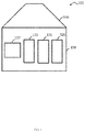
- FIG. 1 there is shown an embodiment illustrating a vehicle which may be any type of vehicle such as, for example, aircraft, spacecraft, space station, satellite, land vehicle and marine vehicle used while implementing the teachings herein.
- vehicle is hereinafter simply referred to as a spacecraft 100.
- teachings herein are not to be limited to only spacecraft.
- the spacecraft 100 is configured from multiple preconstructed assemblies such as assemblies 156, 158 shown in FIG. 1 .
- assemblies 156, 158 shown in FIG. 1 .
- the spacecraft 100 is depicted as having only the two assemblies 156, 158, any number of assemblies may be utilized to configure a vehicle such as the spacecraft 100.
- Each of the assemblies is manufactured to include one or more interior systems.
- the assembly 158 includes interior systems 120.
- each assembly may have any number of interior systems 120.
- An interior system 120 can be, for example, a life support system, air revitalization system, pressure control system, and the like.
- Each system may include, for example, various subsystems depending on the intended function such as controllers, processors, fans, actuators, valves, regulators, motors, generators, heat exchangers, carbon dioxide removal systems, trace contaminant control, smoke detectors and the like.
- the interior systems and subsystems may be hardened against radiation so that they may function and survive within a radiation environment.
- the spacecraft 100 includes a system control 132 for monitoring and managing the operation and behavior of the spacecraft 100 as well as the interior systems 120.
- the system control 132 receives telemetry data from the spacecraft 100 which it uses to monitor the spacecraft's health.
- the telemetry data contains sampled data to provide information about its internal systems 120.
- the system control 132 is a computerized system similar to a general-purpose computing system that is radiation hardened and that is allocated with mission and internal system requirements which define the system control's operational modes and states.
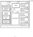
- FIG. 3 illustrates an exemplary embodiment of the physical components (i.e., hardware) of the control system 132.
- FIG. 2 depicts field programmable gate array (FPGA) based circuitry for a space environment for implementing one or more embodiments of the teachings herein.
- An assembly 158 of a vehicle for example the spacecraft 100, includes multiple FPGAs 210.
- Each FPGA 210 includes programable circuity for providing one or more controllers 220, 230.
- Each controller 220, 230 is configured to control at least one internal system 120 such as, for example, the life support system within the spacecraft 100. Because of the FPGA 210, the data acquired from the internal system 120 is real-time data. In one or more embodiments, the data received by the FPGA 210 is at a rate that exceeds a data rate of the system control 132 of the spacecraft 100.
- one of the controllers 220, 230 is a primary controller and the other is a secondary controller.
- the controller 220 is the primary controller 220 and the controller 230 is the secondary controller 230.
- the primary controller 220 sends a first sync pulse to the secondary controller 230 and the secondary controller 230 sends a second sync pulse to the primary controller 220.
- the primary and secondary controllers 220, 230 communicate with one another via the sync pulses over a channel of a multiplex of channels 240.
- each of the controllers 220, 230 includes a dedicated sensor of a pair of sensors 250, 260. As shown in FIG. 2 , the primary controller 220 communicates with a dedicated sensor 250 over a dedicated channel of the multiplex of channels 240 and the secondary controller 230 communicates with a dedicated sensor 260 over another different channel of the multiplex of channels 240.
- the primary and secondary controllers 220, 230 are independent or asynchronous controllers in that they operate asynchronously relative to one another. However, in order to share one of the sensors 250, 260, the primary and secondary controllers 220, 230 synchronize use of a shared communication channel from the multiplex of channels 240 in order to share one of the sensors. In other words, although the primary controller 220 receives data from its dedicated sensor 250, at times it is also possible to receive data from the secondary controller's 230 dedicated sensor 260 and it is also possible for the secondary controller 230 to receive data from the primary controller's 220 dedicated sensor 250, so long as the primary and secondary controllers 220, 230 synchronize access to the sensor 250, 260 over the shared communication channel. Thus, each of the controllers 220, 230 are permitted to share the other controller's dedicated sensor 250, 260 so long as the particular shared sensor is not accessed at the same time by both controllers 220, 230 over the shared communication channel.
- the primary controller 220 changes a period of the first sync pulse to the secondary controller 230 to indicate to the secondary controller 230 that the primary controller 220 is synced to the secondary controller 230.
- the secondary controller 230 changes a period of the second sync pulse to the primary controller 220 to indicate to the primary controller 220 that the secondary controller 230 is synced to the primary controller 220. Changing the period of a sync pulse may include, for example, lengthening the period of the sync pulse.
- lengthening the period of the first sync pulse to the secondary controller 230 indicates to the secondary controller 230 that the primary controller 220 is synced to the secondary controller 230 and lengthening the period of the second sync pulse to the primary controller 220 indicates to the primary controller 220 that the secondary controller 230 is synced to the primary controller 220.
- the primary controller 220 reads data from the shared sensor 260 while the secondary controller 220 waits for another sync pulse from the primary controller 220.
- the other sync pulse from the primary controller 220 indicates that the primary controller 220 is no longer reading data from the shared sensor 260.
- another sync pulse from the primary controller 220 is sent to the secondary controller 230 to tell the secondary controller 230 that the primary controller 220 is finished accessing the shared sensor 260.
- the secondary controller 230 begins reading data from the shared sensor 260 and the primary controller 220 waits for another sync pulse from the secondary controller 230.
- the other sync pulse from the secondary controller 230 indicates the secondary controller 230 is no longer reading data from the shared sensor 260 after which the primary controller 220 can access the shared sensor 160 again.
- receipt of the synched pulse by either of the primary and secondary controllers 220, 230 indicates when the other of the primary and secondary controllers 220, 230 is finished utilizing the shared communication channel to a shared sensor 250, 260 and, consequently, receipt of a synched pulse by either of the primary and secondary controllers 220, 230 indicates a status of asynchronicity of the other of the primary and secondary controllers 220, 230.
- the secondary controller 230 can also share access to the data from the primary controller's 220 dedicated sensor 250. In order for the secondary controller 230 to access shared sensor 250, the secondary controller 230 must wait until the primary controller 220 send a sync pulse with a longer period indicating that the primary controller 220 is finished accessing data from the shared sensor 250. While either of the primary and secondary controllers 220, 230 is waiting to access one of the sensors 250, 260 that is dedicated to the other controller, the primary and secondary controllers 220, 230 default to their own dedicated sensor 250, 260. Thus, the secondary controller 230 reads data from its own dedicated sensor 260 while waiting to receive the other sync pulse from the primary controller 220 in order to begin reading data from the sensor 250 as the shared sensor. Also, each of the primary and secondary controllers 220, 230 defaults to its own dedicated sensor when communication between the primary and secondary controllers 220, 230 is lost or when the status of the other of the controller is unknown.
- the control system 132 includes at least one processing unit 302 and a system memory 304.
- the system memory 304 comprises, but is not limited to, volatile storage (e.g., random access memory), non-volatile storage (e.g., read-only memory), flash memory, or any combination of such memories.
- the system memory 304 includes an operating system 305 and one or more program modules 306 suitable for running software applications 318.
- the system memory 304 includes one or more diagnostic modules 316 for providing diagnostic information including sensor information and data from the internal systems 120 via the FPGAs 210.
- system memory can includes many other modules such as, for example, a managing or monitoring module for managing and/or monitoring the sensors of the internal systems 120.
- the operating system 305 for example, is suitable for controlling the operation of the control system 132.
- diagnostics module 316 or some other modules can initiate via the FPGAs 210 managing and or monitoring of the functioning of one or more subsystems of the interior systems 140.
- control system 132 has additional features or functionality.
- the control system 132 includes additional data storage devices (removable and/or non-removable) such as, for example, magnetic disks, optical disks, or tape.
- additional storage is illustrated in FIG. 3 by a removable storage device 319 and a non-removable storage device 320.
- a number of program modules and data files are stored in the system memory 304. While executing on the processing unit 302, the program modules 306 (e.g., diagnostics module 316) perform processes including, but not limited to, one or more of the stages or steps of the method 600 illustrated in FIG. 6 . According to an aspect, other program modules are also used.
- the program modules 306 e.g., diagnostics module 316
- the program modules 306 perform processes including, but not limited to, one or more of the stages or steps of the method 600 illustrated in FIG. 6 .
- other program modules are also used.
- the control system 132 has one or more input device(s) 322 such as a keyboard, a mouse, a pen, a sound input device, a touch input device, etc.
- the input device may be a recorder receiving a video feed from one or more video cameras.
- the output device(s) 324 such as a display, speakers, a printer, etc. are also included according to an aspect.
- the aforementioned devices are examples and others may be used.
- the control system 132 includes one or more communication connections 326 allowing communications with ground control and other computing devices. Examples of suitable communication connections 326 include, but are not limited to, radio frequency (RF) transmitter, receiver, and/or transceiver circuitry; universal serial bus (USB), parallel, and/or serial ports.
- RF radio frequency
- USB universal serial bus
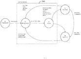
- FIG. 4 depicts a state diagram illustrating the states of one of the controllers 220, 230 while implementing one or more embodiments of the present invention.
- state 0 the particular controller is powered off.
- state 1 includes the controller 220, 230 waiting prior to receiving the sync pulse from the other controller in order to sync with the other controller.
- state 2 as explained above, once the either of the controllers 220, 230 receives the sync pulse from the other controller, the controller 220, 230 receiving the sync pulse is synced with the other of the controllers 220,230.
- FIG. 4 depicts a state diagram illustrating the states of one of the controllers 220, 230 while implementing one or more embodiments of the present invention.
- state 0 the particular controller is powered off.
- state 1 includes the controller 220, 230 waiting prior to receiving the sync pulse from the other controller in order to sync with the other controller.
- state 220, 230 receiving the sync pulse is synced with the other of the controllers 220,
- states 1 and 2 of a controller 220, 230 is grouped by a dashed line 410 to indicate normal operation of the controller 220, 230.
- states 3 and 4 illustrate fault states of a controller 220, 230.
- the controller 220, 230 faults.
- the sync fault may be cleared or the FPGA 210 may be reset and the controller state returned to state 2 in order to wait for another sync pulse.
- the controller 220, 230 may be switched back to state 1 to wait for another sync pulse by clearing the fault or by resetting the FPGA 210.
- the controller 220, 230 may be faulted in order to then command the controller 220, 230 into a new sync as shown at state 4. From state 4, the controller 220, 230 may be returned to state 1 in order to wait for another sync pulse from the other controller 220, 230.
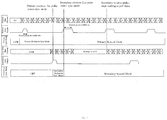
- FIG. 5 depicts an example of the startup synchronization of the pair of controllers 220, 230 according to one or more embodiments of the present invention.
- a sync mode, sync output, and a multiplexed channel for the dedicated sensor 250 of the primary controller 220 is depicted along with a sync mode, sync output, and a multiplexed channel for the dedicated sensor 260 of the secondary controller 230.
- the first vertical dashed line corresponds with the edge of the first shown sync pulse of the secondary sync output from the secondary controller 230 where the primary controller 220 receives the first sync pulse from the secondary controller 230 and enters the sync mode.
- the primary controller 220 outputs its sync pulse to the secondary controller 230.
- the output sync pulse from the primary controller 220 includes a lengthened period for indicating that the primary controller 220 is synced as described above.
- the secondary controller 230 then enters its own sync mode.
- the secondary controller 230 receives another sync pulse as output from the primary controller 220 and the secondary controller 230 stops waiting to poll input.
- one or more embodiments may include a method 600 for providing collision avoidance protection to controllers sharing the same sensor.
- the flow diagram of FIG. 6 illustrates the method 600 that includes process block 610 for sending a first sync pulse via a primary controller to a secondary controller and process block 620 for sending a second sync pulse via the secondary controller to the primary controller.
- the method 600 also includes process block 630 for, in response to receiving the second sync pulse at the primary controller, the primary controller changing a period of the first sync pulse to the secondary controller to indicate to the secondary controller that the primary controller is synced to the secondary controller.
- the method 600 also includes process block 640 for, in response to receiving the first sync pulse at the secondary controller, the secondary controller changing a period of the second sync pulse to the primary controller to indicate to the primary controller that the secondary controller is synced to the primary controller. Also, the method 600 includes process block 650 for reading, via the primary controller, data from a shared sensor while the secondary controller waits for another sync pulse from the primary controller, wherein the other sync pulse indicates that the primary controller is no longer reading data from the shared sensor.
- the method 600 also includes process block 660 for, in response to the secondary controller receiving the other sync pulse from the primary controller indicating the primary controller is no longer reading data from the shared sensor, reading, via the secondary controller, data from the shared sensor and the primary controller waiting for another sync pulse from the secondary controller, wherein the other sync pulse from the secondary controller indicates the secondary controller is no longer reading data from the shared sensor.
- the method 600 may also include one or more other process blocks.
- the method 600 may include where the shared sensor is one of a pair of sensors shared between the primary and secondary controllers and one of the sensors of the pair of sensors is dedicated to the primary controller and the other sensor of the pair of sensors is dedicated to the secondary controller.
- the method 600 may also include where either of the primary and secondary controllers defaults to its own dedicated sensor when a status of the other of the primary and secondary controllers is unknown.
- the method 600 may include each of the primary and secondary controllers defaulting to a dedicated sensor when communication between the primary and secondary controllers is lost.
- the method 600 may also include changing a period of the first sync pulse to the secondary controller to indicate to the secondary controller that the primary controller is synced to the secondary controller comprises lengthening the period of the first sync pulse to the secondary controller to indicate to the secondary controller that the primary controller is synced to the secondary controller and wherein changing the period of the second sync pulse to the primary controller to indicate to the primary controller that the secondary controller is synced to the primary controller comprises lengthening the period of the second sync pulse to the primary controller to indicate to the primary controller that the secondary controller is synced to the primary controller.
- the method 600 may include the primary and secondary controllers sharing a communication channel to the shared sensor and wherein receipt of the sync pulses indicate when each of the primary and secondary controllers is done reading data from the shared sensor over the shared communication channel.
- the method 600 can include the second controller reading data from a dedicated sensor while waiting to receive the other sync pulse from the primary controller in order to begin reading data from the shared sensor and the primary controller reading data from a dedicated sensor while waiting to receive the other sync pulse from the secondary controller in order to begin reading data from the shared sensor.
- the method 600 can include where the primary and secondary controllers are independent controllers that operate asynchronously relative to one another, and wherein the primary and secondary controllers synchronize use of a shared communication channel to the shared sensor.
- the method 600 may also include where receipt of the synched pulse by either of the primary and secondary controllers indicates when the other of the primary and secondary controllers is finished utilizing a shared channel to the shared sensor. Also, the method 600 may include where receipt of the synched pulse by either of the primary and secondary controllers indicates a status of asynchronicity of the other of the primary and secondary controllers.
- the method 600 can include the primary and secondary controllers waiting prior to receiving the second and first sync pulses, respectively, in order to begin reading data from the shared sensor across a shared communication channel and the primary and secondary controllers reading data from respective dedicated sensors while waiting for the first and second sync pulses.
Landscapes
- Engineering & Computer Science (AREA)
- Remote Sensing (AREA)
- Aviation & Aerospace Engineering (AREA)
- Radar, Positioning & Navigation (AREA)
- Physics & Mathematics (AREA)
- General Physics & Mathematics (AREA)
- Automation & Control Theory (AREA)
- Chemical & Material Sciences (AREA)
- Combustion & Propulsion (AREA)
- Computer Networks & Wireless Communication (AREA)
- Arrangements For Transmission Of Measured Signals (AREA)
Applications Claiming Priority (1)
| Application Number | Priority Date | Filing Date | Title |
|---|---|---|---|
| US16/365,261 US11117686B2 (en) | 2019-03-26 | 2019-03-26 | Shared resistive sensor measurement with FPGA based collision avoidance protection |
Publications (2)
| Publication Number | Publication Date |
|---|---|
| EP3716640A1 true EP3716640A1 (fr) | 2020-09-30 |
| EP3716640B1 EP3716640B1 (fr) | 2023-05-10 |
Family
ID=68655324
Family Applications (1)
| Application Number | Title | Priority Date | Filing Date |
|---|---|---|---|
| EP19211137.5A Active EP3716640B1 (fr) | 2019-03-26 | 2019-11-25 | Mesure de capteur résistif partagée comportant une protection anti-collision à base de fpga |
Country Status (2)
| Country | Link |
|---|---|
| US (1) | US11117686B2 (fr) |
| EP (1) | EP3716640B1 (fr) |
Cited By (1)
| Publication number | Priority date | Publication date | Assignee | Title |
|---|---|---|---|---|
| CN113110124A (zh) * | 2021-03-11 | 2021-07-13 | 上海新时达电气股份有限公司 | 双mcu控制方法及控制系统 |
Families Citing this family (3)
| Publication number | Priority date | Publication date | Assignee | Title |
|---|---|---|---|---|
| US12158687B2 (en) | 2020-05-14 | 2024-12-03 | Cirrus Logic, Inc. | System and method for providing increased number of time synchronized outputs by using communicating primary and secondary devices |
| US12143713B2 (en) * | 2020-05-14 | 2024-11-12 | Cirrus Logic, Inc. | Multi-chip camera controller system with inter-chip communication |
| US12143078B2 (en) | 2020-12-11 | 2024-11-12 | Cirrus Logic, Inc. | Circuit element pair matching method and circuit |
Citations (3)
| Publication number | Priority date | Publication date | Assignee | Title |
|---|---|---|---|---|
| WO2016057289A1 (fr) * | 2014-10-09 | 2016-04-14 | Invensense, Inc. | Système et procédé pour synchronisation de système capteur mems |
| US20180198545A1 (en) * | 2017-01-10 | 2018-07-12 | Infineon Technologies Ag | Synchronization mechanism for high speed sensor interface |
| US20190069051A1 (en) * | 2017-08-25 | 2019-02-28 | Honda Motor Co., Ltd. | System and method for synchronized vehicle sensor data acquisition processing using vehicular communication |
Family Cites Families (4)
| Publication number | Priority date | Publication date | Assignee | Title |
|---|---|---|---|---|
| US8176803B1 (en) | 2008-07-29 | 2012-05-15 | Orbital Research Inc. | High-temperature sensor interface and network |
| US8406217B2 (en) | 2010-04-16 | 2013-03-26 | Simmonds Precision Products, Inc. | Synchronizing wireless devices using timestamps and relative clock offsets of the wireless devices |
| US9582452B2 (en) | 2013-06-05 | 2017-02-28 | The Boeing Company | Sensor network using pulse width modulated signals |
| US10031875B2 (en) * | 2014-01-22 | 2018-07-24 | Texas Instruments Incorporated | Switch monitoring system |
-
2019
- 2019-03-26 US US16/365,261 patent/US11117686B2/en active Active
- 2019-11-25 EP EP19211137.5A patent/EP3716640B1/fr active Active
Patent Citations (3)
| Publication number | Priority date | Publication date | Assignee | Title |
|---|---|---|---|---|
| WO2016057289A1 (fr) * | 2014-10-09 | 2016-04-14 | Invensense, Inc. | Système et procédé pour synchronisation de système capteur mems |
| US20180198545A1 (en) * | 2017-01-10 | 2018-07-12 | Infineon Technologies Ag | Synchronization mechanism for high speed sensor interface |
| US20190069051A1 (en) * | 2017-08-25 | 2019-02-28 | Honda Motor Co., Ltd. | System and method for synchronized vehicle sensor data acquisition processing using vehicular communication |
Cited By (2)
| Publication number | Priority date | Publication date | Assignee | Title |
|---|---|---|---|---|
| CN113110124A (zh) * | 2021-03-11 | 2021-07-13 | 上海新时达电气股份有限公司 | 双mcu控制方法及控制系统 |
| CN113110124B (zh) * | 2021-03-11 | 2022-08-19 | 上海新时达电气股份有限公司 | 双mcu控制方法及控制系统 |
Also Published As
| Publication number | Publication date |
|---|---|
| US20200307832A1 (en) | 2020-10-01 |
| EP3716640B1 (fr) | 2023-05-10 |
| US11117686B2 (en) | 2021-09-14 |
Similar Documents
| Publication | Publication Date | Title |
|---|---|---|
| EP3716640B1 (fr) | Mesure de capteur résistif partagée comportant une protection anti-collision à base de fpga | |
| US4634110A (en) | Fault detection and redundancy management system | |
| US7246186B2 (en) | Mobius time-triggered communication | |
| US20100306435A1 (en) | Reconfigurable virtual backplane systems and methods | |
| EP3236325B1 (fr) | Appareil de commande, appareil de relais, procédé de commande pour appareil de commande, procédé de commande pour appareil de relais, programme de commande et support d'informations | |
| EP0408094A2 (fr) | Moniteur d'affichage d'application générale en avionique | |
| EP3376316B1 (fr) | Dispositif esclave, procédé de commande d'un dispositif esclave, programme de traitement d'informations et support d'enregistrement lisible par ordinateur | |
| US20200073355A1 (en) | Control system for controlling safety-critical and non-safety-critical processes with master-minion functionality | |
| JP6747525B2 (ja) | セーフティシステムおよびセーフティコントローラ | |
| US20130253706A1 (en) | Safety signal processing system | |
| KR20170095183A (ko) | 2채널 아키텍처 | |
| Thompson et al. | A CANbus-based safety-critical distributed aeroengine control systems architecture demonstrator | |
| EP2988456B1 (fr) | Procédé et système pour ajouter et communiquer à distance avec des adresses de terminal au-delà d'un protocole de bus standard | |
| EP2705426B1 (fr) | Processeur d'entrée/sortie configurable | |
| EP3564767A1 (fr) | Appareil de support, programme de support et procédé de réglage | |
| US20160134475A1 (en) | Control system, master station, and remote station | |
| RU2667040C1 (ru) | Интегрированная вычислительная система самолета МС-21 | |
| EP3772845B1 (fr) | Convertisseur de protocole, système de transmission de données, procédé de transmission de données et support d'enregistrement lisible par ordinateur non transitoire | |
| US9317024B2 (en) | Automation system | |
| US8539122B2 (en) | Submodule and method for exchanging peripheral data | |
| US10768601B2 (en) | Programmable controller | |
| EP3716068B1 (fr) | Interface de données haute vitesse pour des organes de commande de moteur de système réparti | |
| US20200310936A1 (en) | Reconfigurable stand alone distributed system motor controllers | |
| KR20220122145A (ko) | 무인항공기 네트워크 구조 및 네트워크 구조에서의 동기화 방법 | |
| EP4524919A1 (fr) | Prédiction et configuration de données d'aéronef d`un élément rempacable en escale |
Legal Events
| Date | Code | Title | Description |
|---|---|---|---|
| PUAI | Public reference made under article 153(3) epc to a published international application that has entered the european phase |
Free format text: ORIGINAL CODE: 0009012 |
|
| STAA | Information on the status of an ep patent application or granted ep patent |
Free format text: STATUS: THE APPLICATION HAS BEEN PUBLISHED |
|
| AK | Designated contracting states |
Kind code of ref document: A1 Designated state(s): AL AT BE BG CH CY CZ DE DK EE ES FI FR GB GR HR HU IE IS IT LI LT LU LV MC MK MT NL NO PL PT RO RS SE SI SK SM TR |
|
| AX | Request for extension of the european patent |
Extension state: BA ME |
|
| STAA | Information on the status of an ep patent application or granted ep patent |
Free format text: STATUS: REQUEST FOR EXAMINATION WAS MADE |
|
| 17P | Request for examination filed |
Effective date: 20210326 |
|
| RBV | Designated contracting states (corrected) |
Designated state(s): AL AT BE BG CH CY CZ DE DK EE ES FI FR GB GR HR HU IE IS IT LI LT LU LV MC MK MT NL NO PL PT RO RS SE SI SK SM TR |
|
| RIC1 | Information provided on ipc code assigned before grant |
Ipc: G08C 13/00 20060101ALI20221101BHEP Ipc: H04Q 9/04 20060101AFI20221101BHEP |
|
| GRAP | Despatch of communication of intention to grant a patent |
Free format text: ORIGINAL CODE: EPIDOSNIGR1 |
|
| STAA | Information on the status of an ep patent application or granted ep patent |
Free format text: STATUS: GRANT OF PATENT IS INTENDED |
|
| INTG | Intention to grant announced |
Effective date: 20221215 |
|
| GRAS | Grant fee paid |
Free format text: ORIGINAL CODE: EPIDOSNIGR3 |
|
| GRAA | (expected) grant |
Free format text: ORIGINAL CODE: 0009210 |
|
| STAA | Information on the status of an ep patent application or granted ep patent |
Free format text: STATUS: THE PATENT HAS BEEN GRANTED |
|
| AK | Designated contracting states |
Kind code of ref document: B1 Designated state(s): AL AT BE BG CH CY CZ DE DK EE ES FI FR GB GR HR HU IE IS IT LI LT LU LV MC MK MT NL NO PL PT RO RS SE SI SK SM TR |
|
| REG | Reference to a national code |
Ref country code: GB Ref legal event code: FG4D |
|
| REG | Reference to a national code |
Ref country code: AT Ref legal event code: REF Ref document number: 1567918 Country of ref document: AT Kind code of ref document: T Effective date: 20230515 Ref country code: CH Ref legal event code: EP |
|
| REG | Reference to a national code |
Ref country code: DE Ref legal event code: R096 Ref document number: 602019028676 Country of ref document: DE |
|
| REG | Reference to a national code |
Ref country code: IE Ref legal event code: FG4D |
|
| REG | Reference to a national code |
Ref country code: LT Ref legal event code: MG9D |
|
| REG | Reference to a national code |
Ref country code: NL Ref legal event code: MP Effective date: 20230510 |
|
| REG | Reference to a national code |
Ref country code: AT Ref legal event code: MK05 Ref document number: 1567918 Country of ref document: AT Kind code of ref document: T Effective date: 20230510 |
|
| PG25 | Lapsed in a contracting state [announced via postgrant information from national office to epo] |
Ref country code: SE Free format text: LAPSE BECAUSE OF FAILURE TO SUBMIT A TRANSLATION OF THE DESCRIPTION OR TO PAY THE FEE WITHIN THE PRESCRIBED TIME-LIMIT Effective date: 20230510 Ref country code: PT Free format text: LAPSE BECAUSE OF FAILURE TO SUBMIT A TRANSLATION OF THE DESCRIPTION OR TO PAY THE FEE WITHIN THE PRESCRIBED TIME-LIMIT Effective date: 20230911 Ref country code: NO Free format text: LAPSE BECAUSE OF FAILURE TO SUBMIT A TRANSLATION OF THE DESCRIPTION OR TO PAY THE FEE WITHIN THE PRESCRIBED TIME-LIMIT Effective date: 20230810 Ref country code: NL Free format text: LAPSE BECAUSE OF FAILURE TO SUBMIT A TRANSLATION OF THE DESCRIPTION OR TO PAY THE FEE WITHIN THE PRESCRIBED TIME-LIMIT Effective date: 20230510 Ref country code: ES Free format text: LAPSE BECAUSE OF FAILURE TO SUBMIT A TRANSLATION OF THE DESCRIPTION OR TO PAY THE FEE WITHIN THE PRESCRIBED TIME-LIMIT Effective date: 20230510 Ref country code: AT Free format text: LAPSE BECAUSE OF FAILURE TO SUBMIT A TRANSLATION OF THE DESCRIPTION OR TO PAY THE FEE WITHIN THE PRESCRIBED TIME-LIMIT Effective date: 20230510 |
|
| PG25 | Lapsed in a contracting state [announced via postgrant information from national office to epo] |
Ref country code: RS Free format text: LAPSE BECAUSE OF FAILURE TO SUBMIT A TRANSLATION OF THE DESCRIPTION OR TO PAY THE FEE WITHIN THE PRESCRIBED TIME-LIMIT Effective date: 20230510 Ref country code: PL Free format text: LAPSE BECAUSE OF FAILURE TO SUBMIT A TRANSLATION OF THE DESCRIPTION OR TO PAY THE FEE WITHIN THE PRESCRIBED TIME-LIMIT Effective date: 20230510 Ref country code: LV Free format text: LAPSE BECAUSE OF FAILURE TO SUBMIT A TRANSLATION OF THE DESCRIPTION OR TO PAY THE FEE WITHIN THE PRESCRIBED TIME-LIMIT Effective date: 20230510 Ref country code: LT Free format text: LAPSE BECAUSE OF FAILURE TO SUBMIT A TRANSLATION OF THE DESCRIPTION OR TO PAY THE FEE WITHIN THE PRESCRIBED TIME-LIMIT Effective date: 20230510 Ref country code: IS Free format text: LAPSE BECAUSE OF FAILURE TO SUBMIT A TRANSLATION OF THE DESCRIPTION OR TO PAY THE FEE WITHIN THE PRESCRIBED TIME-LIMIT Effective date: 20230910 Ref country code: HR Free format text: LAPSE BECAUSE OF FAILURE TO SUBMIT A TRANSLATION OF THE DESCRIPTION OR TO PAY THE FEE WITHIN THE PRESCRIBED TIME-LIMIT Effective date: 20230510 Ref country code: GR Free format text: LAPSE BECAUSE OF FAILURE TO SUBMIT A TRANSLATION OF THE DESCRIPTION OR TO PAY THE FEE WITHIN THE PRESCRIBED TIME-LIMIT Effective date: 20230811 |
|
| PG25 | Lapsed in a contracting state [announced via postgrant information from national office to epo] |
Ref country code: FI Free format text: LAPSE BECAUSE OF FAILURE TO SUBMIT A TRANSLATION OF THE DESCRIPTION OR TO PAY THE FEE WITHIN THE PRESCRIBED TIME-LIMIT Effective date: 20230510 |
|
| PG25 | Lapsed in a contracting state [announced via postgrant information from national office to epo] |
Ref country code: SK Free format text: LAPSE BECAUSE OF FAILURE TO SUBMIT A TRANSLATION OF THE DESCRIPTION OR TO PAY THE FEE WITHIN THE PRESCRIBED TIME-LIMIT Effective date: 20230510 |
|
| PG25 | Lapsed in a contracting state [announced via postgrant information from national office to epo] |
Ref country code: SM Free format text: LAPSE BECAUSE OF FAILURE TO SUBMIT A TRANSLATION OF THE DESCRIPTION OR TO PAY THE FEE WITHIN THE PRESCRIBED TIME-LIMIT Effective date: 20230510 Ref country code: SK Free format text: LAPSE BECAUSE OF FAILURE TO SUBMIT A TRANSLATION OF THE DESCRIPTION OR TO PAY THE FEE WITHIN THE PRESCRIBED TIME-LIMIT Effective date: 20230510 Ref country code: RO Free format text: LAPSE BECAUSE OF FAILURE TO SUBMIT A TRANSLATION OF THE DESCRIPTION OR TO PAY THE FEE WITHIN THE PRESCRIBED TIME-LIMIT Effective date: 20230510 Ref country code: EE Free format text: LAPSE BECAUSE OF FAILURE TO SUBMIT A TRANSLATION OF THE DESCRIPTION OR TO PAY THE FEE WITHIN THE PRESCRIBED TIME-LIMIT Effective date: 20230510 Ref country code: DK Free format text: LAPSE BECAUSE OF FAILURE TO SUBMIT A TRANSLATION OF THE DESCRIPTION OR TO PAY THE FEE WITHIN THE PRESCRIBED TIME-LIMIT Effective date: 20230510 Ref country code: CZ Free format text: LAPSE BECAUSE OF FAILURE TO SUBMIT A TRANSLATION OF THE DESCRIPTION OR TO PAY THE FEE WITHIN THE PRESCRIBED TIME-LIMIT Effective date: 20230510 |
|
| REG | Reference to a national code |
Ref country code: DE Ref legal event code: R097 Ref document number: 602019028676 Country of ref document: DE |
|
| PLBE | No opposition filed within time limit |
Free format text: ORIGINAL CODE: 0009261 |
|
| STAA | Information on the status of an ep patent application or granted ep patent |
Free format text: STATUS: NO OPPOSITION FILED WITHIN TIME LIMIT |
|
| 26N | No opposition filed |
Effective date: 20240213 |
|
| PG25 | Lapsed in a contracting state [announced via postgrant information from national office to epo] |
Ref country code: SI Free format text: LAPSE BECAUSE OF FAILURE TO SUBMIT A TRANSLATION OF THE DESCRIPTION OR TO PAY THE FEE WITHIN THE PRESCRIBED TIME-LIMIT Effective date: 20230510 |
|
| PG25 | Lapsed in a contracting state [announced via postgrant information from national office to epo] |
Ref country code: SI Free format text: LAPSE BECAUSE OF FAILURE TO SUBMIT A TRANSLATION OF THE DESCRIPTION OR TO PAY THE FEE WITHIN THE PRESCRIBED TIME-LIMIT Effective date: 20230510 |
|
| REG | Reference to a national code |
Ref country code: CH Ref legal event code: PL |
|
| PG25 | Lapsed in a contracting state [announced via postgrant information from national office to epo] |
Ref country code: MC Free format text: LAPSE BECAUSE OF FAILURE TO SUBMIT A TRANSLATION OF THE DESCRIPTION OR TO PAY THE FEE WITHIN THE PRESCRIBED TIME-LIMIT Effective date: 20230510 |
|
| PG25 | Lapsed in a contracting state [announced via postgrant information from national office to epo] |
Ref country code: LU Free format text: LAPSE BECAUSE OF NON-PAYMENT OF DUE FEES Effective date: 20231125 |
|
| PG25 | Lapsed in a contracting state [announced via postgrant information from national office to epo] |
Ref country code: CH Free format text: LAPSE BECAUSE OF NON-PAYMENT OF DUE FEES Effective date: 20231130 |
|
| GBPC | Gb: european patent ceased through non-payment of renewal fee |
Effective date: 20231125 |
|
| PG25 | Lapsed in a contracting state [announced via postgrant information from national office to epo] |
Ref country code: MC Free format text: LAPSE BECAUSE OF FAILURE TO SUBMIT A TRANSLATION OF THE DESCRIPTION OR TO PAY THE FEE WITHIN THE PRESCRIBED TIME-LIMIT Effective date: 20230510 Ref country code: LU Free format text: LAPSE BECAUSE OF NON-PAYMENT OF DUE FEES Effective date: 20231125 Ref country code: CH Free format text: LAPSE BECAUSE OF NON-PAYMENT OF DUE FEES Effective date: 20231130 |
|
| REG | Reference to a national code |
Ref country code: BE Ref legal event code: MM Effective date: 20231130 |
|
| REG | Reference to a national code |
Ref country code: IE Ref legal event code: MM4A |
|
| PG25 | Lapsed in a contracting state [announced via postgrant information from national office to epo] |
Ref country code: IE Free format text: LAPSE BECAUSE OF NON-PAYMENT OF DUE FEES Effective date: 20231125 |
|
| PG25 | Lapsed in a contracting state [announced via postgrant information from national office to epo] |
Ref country code: GB Free format text: LAPSE BECAUSE OF NON-PAYMENT OF DUE FEES Effective date: 20231125 |
|
| PG25 | Lapsed in a contracting state [announced via postgrant information from national office to epo] |
Ref country code: BE Free format text: LAPSE BECAUSE OF NON-PAYMENT OF DUE FEES Effective date: 20231130 |
|
| PG25 | Lapsed in a contracting state [announced via postgrant information from national office to epo] |
Ref country code: IE Free format text: LAPSE BECAUSE OF NON-PAYMENT OF DUE FEES Effective date: 20231125 Ref country code: GB Free format text: LAPSE BECAUSE OF NON-PAYMENT OF DUE FEES Effective date: 20231125 Ref country code: BE Free format text: LAPSE BECAUSE OF NON-PAYMENT OF DUE FEES Effective date: 20231130 |
|
| PG25 | Lapsed in a contracting state [announced via postgrant information from national office to epo] |
Ref country code: BG Free format text: LAPSE BECAUSE OF FAILURE TO SUBMIT A TRANSLATION OF THE DESCRIPTION OR TO PAY THE FEE WITHIN THE PRESCRIBED TIME-LIMIT Effective date: 20230510 |
|
| PG25 | Lapsed in a contracting state [announced via postgrant information from national office to epo] |
Ref country code: BG Free format text: LAPSE BECAUSE OF FAILURE TO SUBMIT A TRANSLATION OF THE DESCRIPTION OR TO PAY THE FEE WITHIN THE PRESCRIBED TIME-LIMIT Effective date: 20230510 |
|
| PG25 | Lapsed in a contracting state [announced via postgrant information from national office to epo] |
Ref country code: CY Free format text: LAPSE BECAUSE OF FAILURE TO SUBMIT A TRANSLATION OF THE DESCRIPTION OR TO PAY THE FEE WITHIN THE PRESCRIBED TIME-LIMIT; INVALID AB INITIO Effective date: 20191125 |
|
| PG25 | Lapsed in a contracting state [announced via postgrant information from national office to epo] |
Ref country code: HU Free format text: LAPSE BECAUSE OF FAILURE TO SUBMIT A TRANSLATION OF THE DESCRIPTION OR TO PAY THE FEE WITHIN THE PRESCRIBED TIME-LIMIT; INVALID AB INITIO Effective date: 20191125 |
|
| PG25 | Lapsed in a contracting state [announced via postgrant information from national office to epo] |
Ref country code: TR Free format text: LAPSE BECAUSE OF FAILURE TO SUBMIT A TRANSLATION OF THE DESCRIPTION OR TO PAY THE FEE WITHIN THE PRESCRIBED TIME-LIMIT Effective date: 20230510 |
|
| PGFP | Annual fee paid to national office [announced via postgrant information from national office to epo] |
Ref country code: DE Payment date: 20251022 Year of fee payment: 7 |
|
| PGFP | Annual fee paid to national office [announced via postgrant information from national office to epo] |
Ref country code: IT Payment date: 20251022 Year of fee payment: 7 |
|
| PGFP | Annual fee paid to national office [announced via postgrant information from national office to epo] |
Ref country code: FR Payment date: 20251022 Year of fee payment: 7 |
|
| P01 | Opt-out of the competence of the unified patent court (upc) registered |
Free format text: CASE NUMBER: UPC_APP_0019062_3716640/2025 Effective date: 20251222 |