EP3716484A1 - Fahrzeug-benutzer-schnittstelle - Google Patents
Fahrzeug-benutzer-schnittstelle Download PDFInfo
- Publication number
- EP3716484A1 EP3716484A1 EP20155576.0A EP20155576A EP3716484A1 EP 3716484 A1 EP3716484 A1 EP 3716484A1 EP 20155576 A EP20155576 A EP 20155576A EP 3716484 A1 EP3716484 A1 EP 3716484A1
- Authority
- EP
- European Patent Office
- Prior art keywords
- vehicle
- user interface
- adhesive layer
- display glass
- film
- Prior art date
- Legal status (The legal status is an assumption and is not a legal conclusion. Google has not performed a legal analysis and makes no representation as to the accuracy of the status listed.)
- Granted
Links
Images
Classifications
-
- G—PHYSICS
- G06—COMPUTING OR CALCULATING; COUNTING
- G06F—ELECTRIC DIGITAL DATA PROCESSING
- G06F3/00—Input arrangements for transferring data to be processed into a form capable of being handled by the computer; Output arrangements for transferring data from processing unit to output unit, e.g. interface arrangements
- G06F3/01—Input arrangements or combined input and output arrangements for interaction between user and computer
- G06F3/03—Arrangements for converting the position or the displacement of a member into a coded form
- G06F3/033—Pointing devices displaced or positioned by the user, e.g. mice, trackballs, pens or joysticks; Accessories therefor
- G06F3/039—Accessories therefor, e.g. mouse pads
- G06F3/0393—Accessories for touch pads or touch screens, e.g. mechanical guides added to touch screens for drawing straight lines, hard keys overlaying touch screens or touch pads
-
- H—ELECTRICITY
- H03—ELECTRONIC CIRCUITRY
- H03K—PULSE TECHNIQUE
- H03K17/00—Electronic switching or gating, i.e. not by contact-making and –breaking
- H03K17/94—Electronic switching or gating, i.e. not by contact-making and –breaking characterised by the way in which the control signals are generated
- H03K17/965—Switches controlled by moving an element forming part of the switch
- H03K17/975—Switches controlled by moving an element forming part of the switch using a capacitive movable element
-
- H—ELECTRICITY
- H01—ELECTRIC ELEMENTS
- H01H—ELECTRIC SWITCHES; RELAYS; SELECTORS; EMERGENCY PROTECTIVE DEVICES
- H01H3/00—Mechanisms for operating contacts
- H01H3/02—Operating parts, i.e. for operating driving mechanism by a mechanical force external to the switch
- H01H2003/026—Operating parts, i.e. for operating driving mechanism by a mechanical force external to the switch specially adapted to avoid injury to occupants of a car during an accident
-
- H—ELECTRICITY
- H03—ELECTRONIC CIRCUITRY
- H03K—PULSE TECHNIQUE
- H03K2217/00—Indexing scheme related to electronic switching or gating, i.e. not by contact-making or -breaking covered by H03K17/00
- H03K2217/94—Indexing scheme related to electronic switching or gating, i.e. not by contact-making or -breaking covered by H03K17/00 characterised by the way in which the control signal is generated
- H03K2217/94057—Rotary switches
- H03K2217/94073—Rotary switches with capacitive detection
-
- H—ELECTRICITY
- H03—ELECTRONIC CIRCUITRY
- H03K—PULSE TECHNIQUE
- H03K2217/00—Indexing scheme related to electronic switching or gating, i.e. not by contact-making or -breaking covered by H03K17/00
- H03K2217/94—Indexing scheme related to electronic switching or gating, i.e. not by contact-making or -breaking covered by H03K17/00 characterised by the way in which the control signal is generated
- H03K2217/96—Touch switches
- H03K2217/96062—Touch switches with tactile or haptic feedback
-
- H—ELECTRICITY
- H03—ELECTRONIC CIRCUITRY
- H03K—PULSE TECHNIQUE
- H03K2217/00—Indexing scheme related to electronic switching or gating, i.e. not by contact-making or -breaking covered by H03K17/00
- H03K2217/94—Indexing scheme related to electronic switching or gating, i.e. not by contact-making or -breaking covered by H03K17/00 characterised by the way in which the control signal is generated
- H03K2217/96—Touch switches
- H03K2217/9607—Capacitive touch switches
- H03K2217/960705—Safety of capacitive touch and proximity switches, e.g. increasing reliability, fail-safe
Definitions
- the present invention relates to a vehicle user interface with a display glass that is coated with a film and on which at least one actuating element is attached, via which inputs can be made.
- the invention also relates to a vehicle with such a vehicle-user interface and the use of such a vehicle-user interface in the vehicle.
- WO 2018/086793 A1 describes a vehicle-user interface with a touch-sensitive input surface, a movably mounted actuating element being provided on the input surface.
- the risk of injury in the event of a head impact on the actuating element is to be reduced by predetermined breaking points on the housing of the vehicle-user interface or on the carrier of the touch-sensitive input surface.
- the invention relates to a vehicle user interface.
- the vehicle-user interface in the context of the invention means a device for making control inputs relating to the vehicle or vehicle components.
- the driver of the vehicle is understood as the user, also known as the operator.
- the vehicle-user interface has a display glass that is coated with a film with at least one opening.
- a haptic actuating element is glued to the display glass within the at least one opening by means of a first adhesive layer. The bonding is such that an actuation of the actuation element can be detected via the display glass and can subsequently be converted into an input command.
- the user can be supported with his inputs, in particular if he is used to conventional operating devices with movably mounted actuating elements.
- an operation can also be carried out without visual control and without distraction from the traffic situation by grasping the actuating element.
- further operating options can be provided via further actuating elements and / or further vehicle components.
- the vehicle-user interface preferably provides a touch-sensitive glass surface, the display glass, via which inputs can be made.
- this glass surface is combined with a display, e.g. B. a pixel matrix display. This is known as a touch screen.
- a display-free glass surface which can be referred to as a touchpad.
- touches made on the display glass through the display glass are touch-sensitive Input device detected. These entries expand the possibilities for the user to make entries. He can make entries by touching the display glass or by actuating the actuating element. It is also possible to provide haptic feedback to the user through the actuating element.
- Providing at least one opening in the film for gluing the actuating element enables the display glass to be coated with the film in areas around the actuating element and thus allows the positive properties of the film for the area of the display glass visible to the user.
- the opening is located under the actuating element and the absence of the film under the actuating element is therefore imperceptible in normal operation. Thanks to the opening in the film, the vehicle-user interface is also simple and easy to assemble.
- the touch-sensitive input device is glued to the display glass by means of a second adhesive layer.
- the second adhesive layer is on the side of the display glass facing away from the film.
- the touch-sensitive input device can be used to detect the position of the actuating element.
- the touch-sensitive input device can, for example, also be used for touch detection on the display glass.
- the first adhesive layer is harder than the second adhesive layer.
- the adhesive connection between the display glass and the touch-sensitive input device is thus softer than the adhesive connection between the mechanical actuating element and the display glass. This enables the force to be transmitted directly to the display glass when a strong force is exerted on the actuation element, this can break, and the actuation element is thus lowered in the direction of the vehicle / user interface.
- the soft second adhesive layer enables and thus also promotes the lowering of the actuating element. All of this reduces the risk of injury to the user.
- the first adhesive layer has a Shore hardness D of greater than 30, for example greater than 35, preferably greater than or equal to 40.
- the Shore hardness is defined based on DIN EN ISO 868, for example.
- the first adhesive layer consists for example of an adhesive based on acrylates and hardens under the action of light and / or moisture and / or heat.
- the second adhesive layer has a Shore hardness 00 of less than 90, for example less than 70, preferably less than 50. This Shore hardness is defined, for example, based on DIN ISO 53505, after 72 hours of curing at room temperature.
- the second adhesive layer consists of an adhesive based on acrylates and cures under the action of light and / or moisture and / or heat.
- the vehicle-user interface can have one or more further actuation elements.
- the one or more further actuating elements like the at least one actuating element, are glued to the display glass in an opening in the film by the first adhesive layer so that actuation of the actuating element can be detected via the display glass.
- one or more of the input elements can be designed as rotary actuators. In this way, the input can be further adapted to the respective requirements.
- the film is a splinter protection film and / or an anti-fingerprint film and / or an anti-reflection film.
- the film is a film which has all three properties.
- the splinter protection film enables the actuation element to be pressed into the display glass in the event of an impact on the mechanical actuating element and the display glass to shatter through the film as a result but prevents splinters from getting into the vehicle interior.
- the anti-reflection film increases the comfort for the user by improving the readability of the display for the user.
- the anti-fingerprint film enables a clean exterior of the vehicle-user interface without annoying fingerprints on the display glass.
- the film is glued to the display glass by means of a third adhesive layer.
- the third adhesive layer can, for example, also consist of adhesive based on acrylates.
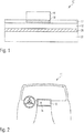
- Figure 1 shows a section through a vehicle user interface 10 with a display glass 12 and a film 14.
- a mechanical operating element 16 is glued to the display glass 12 by means of a first adhesive layer 18 in an opening in the film 14.
- the display glass 12 is glued to a touch-sensitive input device 22 via a second adhesive layer 20.
- the vehicle-user interface 10 realizes a touchscreen that can recognize inputs from a user by touching the display glass 12.
- inputs made by a user via the mechanical operating element 16 can be recognized.
- the operating element 16 is preferably implemented as a rotary actuator that is rotatably mounted.
- the operating element 16 can also optionally be driven by a motor by an actuator (not shown) for generating haptic feedback.
- Figure 2 shows an insight into the interior of a vehicle 30 with a vehicle-user interface 10 with an operating element 16.
- the requirements are high to ensure impact protection and to keep the risk of injury as low as possible in the event of a possible accident.
- the aim should be for the vehicle-user interface to yield and divert the forces that occur into the interior and thus reduce the forces acting on the head.
- This is achieved by the adhesive according to the invention by means of the first adhesive layer 18 of the actuating element on the display glass 12.
- the hardness of the first adhesive layer 18 is comparatively hard, in particular harder than the hardness of the second adhesive layer 20, so that the force in the event of an impact acts directly on the display glass 12 and causes it to shatter.
- the applied film 14 prevents the splinters from penetrating into the interior of the vehicle 30.
Landscapes
- Engineering & Computer Science (AREA)
- General Engineering & Computer Science (AREA)
- Theoretical Computer Science (AREA)
- Human Computer Interaction (AREA)
- Physics & Mathematics (AREA)
- General Physics & Mathematics (AREA)
- Position Input By Displaying (AREA)
- Fittings On The Vehicle Exterior For Carrying Loads, And Devices For Holding Or Mounting Articles (AREA)
Abstract
Description
- Die vorliegende Erfindung betrifft eine Fahrzeug-Benutzer-Schnittstelle mit einem Displayglas, das mit einer Folie beschichtet ist und auf dem mindestens ein Betätigungselement angebracht ist, über das Eingaben vorgenommen werden können. Die Erfindung betrifft außerdem ein Fahrzeug mit einer solchen Fahrzeug-Benutzer-Schnittstelle und die Verwendung einer solchen Fahrzeug-Benutzer-Schnittstelle im Fahrzeug.
- In der
WO 2018/086793 A1 wird eine Fahrzeug-Benutzer-Schnittstelle mit einer berührsensitiven Eingabefläche beschrieben, wobei an der Eingabefläche ein beweglich befestigtes Betätigungselement vorgesehen ist. Durch Sollbruchstellen am Gehäuse der Fahrzeug-Benutzer-Schnittstelle oder am Träger der berührsensitiven Eingabefläche soll das Verletzungsrisiko im Falle eines Kopfaufpralls auf das Betätigungselement verringert werden. - Vor diesem Hintergrund besteht Bedarf nach einer Lösung für eine Fahrzeug-Benutzer-Schnittstelle mit einfacherem Aufbau und im Vergleich verringertem Verletzungsrisiko. Diese Aufgabe wird gelöst durch eine Fahrzeug-Benutzer-Schnittstelle gemäß Patentanspruch 1. Eine gleichermaßen vorteilhafte Verwendung ist Gegenstand des nebengeordneten Verwendungsanspruchs 11. Vorteilhafte Ausgestaltungen sind jeweils Gegenstand der abhängigen Ansprüche.
- Die Erfindung betrifft eine Fahrzeug-Benutzer-Schnittstelle. Die Fahrzeug-Benutzer-Schnittstelle im Sinne der Erfindung meint eine Einrichtung zur Vornahme von Steuerungseingaben betreffend das Fahrzeug oder Fahrzeugkomponenten. Als Nutzer, auch Bedienter genannt, wird unter anderem der Fahrer des Fahrzeugs verstanden. Die Fahrzeug-Benutzer-Schnittstelle weist ein Displayglas auf, das mit einer Folie mit mindestens einer Öffnung beschichtet ist. Ein haptisches Betätigungselement ist innerhalb der mindestens einen Öffnung mittels einer ersten Klebeschicht auf dem Displayglas aufgeklebt. Die Klebung ist so, dass eine Betätigung des Betätigungsefements über das Displayglas erfassbar ist und im folgenden in einen Eingabebefehl umgesetzt werden kann.
- Durch eine solche Verklebung des Betätigungselements direkt auf dem Displayglas können die bei einem Kopfaufschlag auftretenden Kräfte direkt in das Displayglas abgeleitet werden. Dieses bricht bei extremer Belastung, z. B. bei einem Aufprall, und gewährleistet ein Abtauchen des Betätigungselements in die Fahrzeug-Benutzer-Schnittstelle. Das Verletzungsrisiko für den Benutzer wird so vermindert. Durch das direkte Aufkleben des Betätigungselements auf dem Displayglas ohne die Folie als Zwischenlage, ist die Verbindung zwischen Betätigungselement und Displayglas starrer und damit brüchiger und stellt damit eine Art Sollbruchstelle dar. Dies ist im Falle eines Aufpralls erwünscht, da das Betätigungselement bei einem Aufprall in der Fahrzeug-Benutzer-Schnittstelle versenkt werden soll und nicht weiterhin vorstehen soll. Ein weiteres Vorstehen vor das Displayglas könnte möglicherweise zu schwerwiegenderen Verletzungen führen.
- Durch das Vorsehen des Betätigungselements kann der Nutzer bei seinen Eingaben unterstützt werden, insbesondere wenn er an herkömmliche Bediengeräte mit beweglich gelagerten Betätigungselementen gewöhnt ist. Außerdem kann dadurch eine Bedienung auch ohne visuelle Kontrolle und ohne Ablenkung vom Verkehrsgeschehen durch Ergreifen des Betätigungselements durchgeführt werden. Neben der über das Displayglas und neben der über das Betätigungselement gegebenen Eingabeoption können weitere Bedienoptionen über weitere Betätigungselemente und/oder weitere Fahrzeugkomponenten vorgesehen sein.
- Bevorzugt stellt die Fahrzeug-Benutzer-Schnittstelle eine berührempfindlichen Glasfläche, das Displayglas, zu Verfügung, über den Eingaben vorgenommen werden können. Diese Glasfläche ist in einer Ausgestaltung mit einer Anzeige kombiniert, z. B. einer Pixelmatrixanzeige. Dies wird als Touchscreen bezeichnet. In einer anderen Ausgestaltung handelt es sich um eine anzeigelose Glasfläche, welche als Touchpad bezeichnet werden kann.
- Für die Ausgestaltung als Touchscreen oder Touchpad werden auf dem Displayglas vorgenommene Berührungen durch das Displayglas hindurch von einer berührempfindlichen Eingabevorrichtung erfasst. Diese Eingaben erweitern die Möglichkeiten für den Nutzer, Eingaben vorzunehmen. Er kann durch Berührung des Displayglases oder durch Betätigung des Betätigungselementes Eingaben vornehmen. Es ist ebenfalls möglich, ein haptisches Feedback durch das Betätigungselement an den Nutzer vorzusehen.
- In der Folie mindestens eine Öffnung für die Klebung des Betätigungselements vorzusehen ermöglicht, die Beschichtung des Displayglases mit der Folie in Gebieten um das Betätigungselement herum und erlaubt so die positiven Eigenschaften der Folie für den für den Benutzer sichtbaren Bereich des Displayglases. Die Öffnung befindet sich unter dem Betätigungselement und das Fehlen der Folie unter dem Betätigungselement ist somit im Normalbetrieb nicht wahrnehmbar im normalen Betrieb. Durch die Öffnung in der Folie ist die Fahrzeug-Benutzer-Schnittstelle zudem einfach aufgebaut und einfach montierbar.
- In einer Ausführungsform der Erfindung ist die berührempfindliche Eingabevorrichtung mittels einer zweiten Klebeschicht mit dem Displayglas verklebt. Die zweite Klebeschicht befindet sich auf der von der Folie abgewandten Seite des Displayglases. Die berührempfindliche Eingabevorrichtung kann zur Positionsdetektion des Betätigungselement verwendet werden. Die berührempfindliche Eingabevorrichtung kann beispielsweise auch zur Berührdetektion auf dem Displayglas verwendet werden.
- In einer bevorzugten Ausführungsform der Erfindung ist die erste Klebeschicht härter als die zweite Klebeschicht. Damit ist die Klebeverbindung zwischen dem Displayglas und der berührempfindlichen Eingabevorrichtung weicher als die Klebeverbindung zwischen dem mechanischen Betätigungselement und dem Displayglas. Dies ermöglicht, dass bei starker Krafteinwirkung auf das Betätigungselement die Kraft unmittelbar an das Displayglas übertragen wird, dieses brechen kann, und das Betätigungselement somit in Richtung Fahrzeug-Benutzer-Schnittstelle abgesenkt wird. Die weiche zweite Klebeschicht ermöglicht und befördert damit ebenfalls das Absenken des Betätigungselementes. All dies vermindert das Verletzungsrisiko für den Nutzer.
- In einer Ausführungsform der Erfindung weist die erste Klebeschicht eine Shore Härte D von größer 30, zum Beispiel von größer 35, bevorzugt von größer oder gleich 40 auf. Die Shore Härte ist beispielsweise in Anlehnung an DIN EN ISO 868 definiert. Die erste Klebeschicht besteht dabei beispielsweise aus einem Klebstoff auf der Basis von Acrylaten und härtet unter Einwirkung von Licht und/oder Feuchtigkeit und/oder Wärme aus.
- In einer Ausführungsform der Erfindung weist die zweite Klebeschicht eine Shore Härte 00 von kleiner 90, zum Beispiel von kleiner 70, bevorzugt von kleiner 50 auf. Diese Shore Härte ist beispielsweise in Anlehnung an DIN ISO 53505, nach 72 Stunden Härtung bei Raumtemperatur definiert. Beispielsweise besteht die zweite Klebeschicht aus einem Klebstoff auf der Basis von Acrylaten und härtet unter Einwirkung von Licht und/oder Feuchtigkeit und/oder Wärme aus.
- Die Fahrzeug-Benutzer-Schnittstelle kann neben dem einen Betätigungselement ein oder mehrere weitere Betätigungselemente aufweisen. Dabei ist das eine oder sind die mehreren weiteren Betätigungselemente ebenfalls wie das mindestens eine Betätigungselement in einer Öffnung der Folie mit dem Displayglas durch die erste Klebeschicht so verklebt, dass eine Betätigung des Betätigungselements über das Displayglas erfassbar ist.
- In Ausführungsformen der Erfindung kann eines oder mehrere der Eingabeelemente als Drehsteller ausgebildet sein. Auf diese Weise lässt sich die Eingabe weiter an die jeweiligen Erfordernisse anpassen.
- In einer bevorzugten Ausführungsform der Erfindung handelt es sich bei der Folie um einen Splitterschutzfolie und/oder eine Anti-Fingerabdruck-Folie und/oder um eine Anti-Reflexions-Folie. In einer Ausführungsform der Erfindung handelt es sich bei der Folie um eine Folie die alle drei Eigenschaften aufweist. Besonders die Splitterschutzfolie ermöglicht es, dass bei einem Aufprall auf das mechanische Betätigungselement das Betätigungselement in die Displayglas gedrückt wird und das Displayglas infolgedessen zersplittert, es durch die Folie aber verhindert wird, dass Splitter in den Fahrzeuginnenraum gelangen. Die Anti-Reflexion-Folie erhöht den Komfort für den Nutzer, indem sie die Ablesbarkeit des Displays für den Nutzer verbessert. Die Anti-Fingerabdruck-Folie ermöglicht ein sauberes Äußeres der Fahrzeug-Benutzer-Schnittstelle, ohne störende Fingerabdrücke auf dem Displayglas.
- In einer Ausführungsform der Erfindung ist die Folie mittels einer dritten Klebeschicht auf dem Displayglas aufgeklebt. Die dritte Klebeschicht kann beispielsweise ebenfalls aus Klebstoff auf der Basis von Acrylaten bestehen.
- Weitere Merkmale und Vorteile der Erfindung ergeben sich aus der folgenden Beschreibung von nicht einschränkend zu verstehenden Ausführungsbeispielen der Erfindung, die im Folgenden unter Bezugnahme auf die Figuren näher erläutert wird. In den Figuren bezeichnen gleiche Bezugszeichen gleiche oder gleich wirkende Elemente. Es zeigen schematisch:
- Fig. 1
- einen Schnitt durch eine Fahrzeug-Benutzer-Schnittstelle mit einem Bedienelement;
- Fig. 2
- ein Fahrzeug mit der Fahrzeug-Benutzer-Schnittstelle.
-
Figur 1 zeigt einen Schnitt durch eine Fahrzeug-Benutzer-Schnittstelle 10 mit einem Displayglas 12 und einer Folie 14. In einer Öffnung der Folie 14 ist ein mechanisches Bedienelement 16 mittels einer ersten Klebeschicht 18 auf das Displayglas 12 aufgeklebt. Auf der von der Folie abgewandten Seite ist das Displayglas 12 über eine zweite Klebeschicht 20 mit einer berührempfindlichen Eingabevorrichtung 22 verklebt. In die berührempfindliche Eingabevorrichtung 22 ist eine kapazitive, resistive und/oder induktive Detektionseinrichtung integriert, durch die die Berührsensitivität realisiert werden kann. Die Fahrzeug-Benutzer-Schnittstelle 10 realisiert einen Touchscreen, der Eingaben eines Nutzers über Berührungen auf dem Displayglas 12 erkennen kann. Zusätzlich können über das mechanische Bedienelement 16 vorgenommene Eingaben eines Nutzers erkannt werden. Bevorzugt ist das Bedienelement 16 als Drehsteller realisiert, der drehbar gelagert ist. Das Bedienelement 16 kann außerdem optional durch einen nicht dargestellten Aktor zur Erzeugung eines haptischen Feedbacks motorisch angetrieben werden. -
Figur 2 zeigt einen Einblick in das Innere eines Fahrzeuges 30 mit einer Fahrzeug-Benutzer-Schnittstelle 10 mit einem Bedienelement 16. Besonders in Fahrzeugen sind die Anforderungen hoch, Aufprallschutz zu gewährleisten und das Verletzungsrisiko bei einem möglichen Unfall möglichst gering zu halten. Insbesondere bei einem Kopfaufprall auf der Fahrzeug-Benutzer-Schnittstelle ist es anzustreben, dass die Fahrzeug-Benutzer-Schnittstelle nachgibt und die auftretenden Kräfte ins Innere ableitet und so die auf den Kopf wirkenden Kräfte verringert. Dies wird durch die erfindungsgemäße Klebung mittels der ersten Klebeschicht 18 des Betätigungselementes auf das Displayglas 12 erreicht. Die Härte der ersten Klebeschicht 18 ist vergleichsweise hart, insbesondere härter als die Härte der zweiten Klebeschicht 20, gewählt, so dass die Kraft bei einem Aufprall direkt auf das Displayglas 12 wirkt und dieses zum Zersplittern bringt. Durch die aufgebrachte Folie 14 wird dabei ein Eindringen der Splitter in den Innenraum des Fahrzeuges 30 verhindert. - Die hierin offenbarte erfindungsgemäße Anordnung ist nicht auf die hierin offenbarten Ausführungsformen beschränkt, sondern umfasst jeweils auch gleich wirkende weitere Ausführungsformen, die sich aus technisch sinnvollen weiteren Kombinationen der hierin beschriebenen Merkmale der Schaltungsanordnung ergeben. Insbesondere sind die hierin vorstehend in der allgemeinen Beschreibung und der Figurenbeschreibung genannten und/oder in den Figuren alleine gezeigten Merkmale und Merkmalskombinationen nicht nur in den jeweils hierin explizit angegebenen Kombinationen, sondern auch in anderen Kombinationen oder in Alleinstellung verwendbar, ohne den Rahmen der vorliegenden Erfindung zu verlassen.
-
- 10
- Fahrzeug-Benutzer-Schnittstelle
- 12
- Displayglas
- 14
- Folie
- 16
- Betätigungselement
- 18
- erste Klebeschicht
- 20
- zweite Klebeschicht
- 22
- berührempfindliche Eingabevorrichtung
- 30
- Fahrzeug
Claims (11)
- Fahrzeug-Benutzer-Schnittstelle (10) mit einem Displayglas (12), das mit einer Folie (14) beschichtet ist, welche mindestens eine Öffnung aufweist, und mit mindestens einem an dem Displayglas (12) angebrachten Betätigungselement (16), das innerhalb der mindestens einen Öffnung so mittels einer ersten Klebeschicht (18) auf dem Displayglas (12) aufgeklebt ist, dass eine Betätigung des Betätigungselements (16) über das Displayglas (12) erfassbar ist.
- Fahrzeug-Benutzer-Schnittstelle nach Anspruch 1, dadurch gekennzeichnet, dass das Displayglas (12) auf seiner von der Folie (14) abgewandten Seite mittels einer zweiten Klebeschicht (20) mit einer berührempfindlichen Eingabevorrichtung (22) verklebt ist.
- Fahrzeug-Benutzer-Schnittstelle nach Anspruch 2, dadurch gekennzeichnet, dass die erste Klebeschicht (18) härter als die zweite Klebeschicht (20) ist.
- Fahrzeug-Benutzer-Schnittstelle nach einem der vorhergehenden Ansprüche, dadurch gekennzeichnet, dass die erste Klebeschicht (18) eine Shore Härte D von größer 30, zum Beispiel von größer 35, bevorzugt von größer oder gleich 40, aufweist.
- Fahrzeug-Benutzer-Schnittstelle nach einem der Ansprüche 2 bis 4,
dadurch gekennzeichnet, dass die zweite Klebeschicht (20) eine Shore Härte 00 von kleiner 90, zum Beispiel von kleiner 70, bevorzugt von kleiner 50, aufweist. - Fahrzeug-Benutzer-Schnittstelle nach einem der Ansprüche 2 bis 5,
dadurch gekennzeichent, dass die erste und/oder zweite Klebeschicht (18, 20) Klebstoff auf Basis von Acrylaten aufweist. - Fahrzeug-Benutzer-Schnittstelle nach einem der vorhergehenden Ansprüche, dadurch gekennzeichnet, dass das Betätigungselement (16) drehbeweglich gelagert ist.
- Fahrzeug-Benutzer-Schnittstelle nach einem der vorhergehenden Ansprüche, dadurch gekennzeichnet, dass es sich bei der Folie (14) um eine Splitterschutzfolie und/oder eine Anti-Fingerabdruck-Folie und/oder um eine Anti-Reflexions-Folie handelt.
- Fahrzeug-Benutzer-Schnittstelle nach einem der vorhergehenden Ansprüche, dadurch gekennzeichnet, dass die Folie (14) mittels einer dritten Klebeschicht auf dem Displayglas (12) aufgeklebt ist, wobei die dritte Klebeschicht insbesondere gleich der ersten Klebeschicht sein kann.
- Fahrzeug (30) mit einer Fahrzeug-Benutzer-Schnittstelle (10) nach einem der vorhergehenden Ansprüche.
- Verwendung der Fahrzeug-Benutzer-Schnittstelle (10) nach einem der Ansprüche 1 bis 9 in einem Fahrzeug (30),
Applications Claiming Priority (1)
| Application Number | Priority Date | Filing Date | Title |
|---|---|---|---|
| DE102019107843.1A DE102019107843A1 (de) | 2019-03-27 | 2019-03-27 | Fahrzeug-Benutzer-Schnittstelle |
Publications (2)
| Publication Number | Publication Date |
|---|---|
| EP3716484A1 true EP3716484A1 (de) | 2020-09-30 |
| EP3716484B1 EP3716484B1 (de) | 2022-03-30 |
Family
ID=69526011
Family Applications (1)
| Application Number | Title | Priority Date | Filing Date |
|---|---|---|---|
| EP20155576.0A Active EP3716484B1 (de) | 2019-03-27 | 2020-02-05 | Fahrzeug-benutzer-schnittstelle |
Country Status (2)
| Country | Link |
|---|---|
| EP (1) | EP3716484B1 (de) |
| DE (1) | DE102019107843A1 (de) |
Families Citing this family (1)
| Publication number | Priority date | Publication date | Assignee | Title |
|---|---|---|---|---|
| DE102025123746A1 (de) | 2025-06-18 | 2026-04-16 | Audi Aktiengesellschaft | Aufprallsichere flexible Anzeigeeinheit für ein Fahrzeug |
Citations (4)
| Publication number | Priority date | Publication date | Assignee | Title |
|---|---|---|---|---|
| DE102010010574A1 (de) * | 2010-03-08 | 2011-09-08 | Volkswagen Ag | Bedienvorrichtung für ein Fahrzeug |
| EP2695923A2 (de) * | 2012-08-07 | 2014-02-12 | PiOptix GmbH | Verfahren zur durchsichtigen Verklebung von transparenten Schichten |
| WO2018086793A1 (de) | 2016-11-09 | 2018-05-17 | Preh Gmbh | Fahrzeug-benutzer-schnittstelle mit berührsensitiver eingabefläche und an der eingabefläche beweglich befestigtem betätigungsteil und verringertem verletzungsrisiko |
| US20180253119A1 (en) * | 2015-09-15 | 2018-09-06 | Preh Gmbh | Assembly of an electric display and a control dial having foreign-body ingress protection, view protection, and/or light isolation |
Family Cites Families (1)
| Publication number | Priority date | Publication date | Assignee | Title |
|---|---|---|---|---|
| US8199114B1 (en) * | 2000-09-26 | 2012-06-12 | Denny Jaeger | Touch sensor control devices |
-
2019
- 2019-03-27 DE DE102019107843.1A patent/DE102019107843A1/de not_active Withdrawn
-
2020
- 2020-02-05 EP EP20155576.0A patent/EP3716484B1/de active Active
Patent Citations (4)
| Publication number | Priority date | Publication date | Assignee | Title |
|---|---|---|---|---|
| DE102010010574A1 (de) * | 2010-03-08 | 2011-09-08 | Volkswagen Ag | Bedienvorrichtung für ein Fahrzeug |
| EP2695923A2 (de) * | 2012-08-07 | 2014-02-12 | PiOptix GmbH | Verfahren zur durchsichtigen Verklebung von transparenten Schichten |
| US20180253119A1 (en) * | 2015-09-15 | 2018-09-06 | Preh Gmbh | Assembly of an electric display and a control dial having foreign-body ingress protection, view protection, and/or light isolation |
| WO2018086793A1 (de) | 2016-11-09 | 2018-05-17 | Preh Gmbh | Fahrzeug-benutzer-schnittstelle mit berührsensitiver eingabefläche und an der eingabefläche beweglich befestigtem betätigungsteil und verringertem verletzungsrisiko |
Also Published As
| Publication number | Publication date |
|---|---|
| DE102019107843A1 (de) | 2020-10-01 |
| EP3716484B1 (de) | 2022-03-30 |
Similar Documents
| Publication | Publication Date | Title |
|---|---|---|
| EP2972698B1 (de) | Verfahren zum betreiben eines berührungsempfindlichen bediensystems und vorrichtung mit einem solchen bediensystem | |
| EP1545002B1 (de) | Piezoschalter | |
| EP3574396A1 (de) | Verfahren zum betreiben einer mensch-maschinen-schnittstelle sowie mensch-maschinen-schnittstelle | |
| EP2562630B1 (de) | Bedienvorrichtung | |
| DE102018103350A1 (de) | Bedienelement für einen Fahrzeuginnenraum | |
| DE20102197U1 (de) | Touchscreen mit einer für den Benutzer bestätigenden Berührungseingabe | |
| EP2574881A1 (de) | Verfahren zum Betrieb eines Bediensystems für ein Fahrzeug und Bediensystem für ein Fahrzeug | |
| DE102007002401A1 (de) | Medizinische Untersuchungs- oder Interventionseinrichtung | |
| EP3508967B1 (de) | Verfahren zum betreiben einer mensch-maschinen-schnittstelle sowie mensch-maschinen-schnittstelle | |
| EP1631975B1 (de) | Bedienelement | |
| DE102007015681A1 (de) | Bedienelement für Kraftfahrzeuge | |
| DE102014011118B4 (de) | Verfahren zum Bedienen einer Lichtfunktion von Kraftfahrzeugscheinwerfern und Kraftfahrzeug mit einer Anzeigeeinrichtung und einem Bedienelement für eine Bedienung der Lichtfunktion der Kraftfahrzeugscheinwerfer | |
| EP3716484B1 (de) | Fahrzeug-benutzer-schnittstelle | |
| DE102016108899A1 (de) | Kombiniertes Ein- und Ausgabegerät und Verfahren zur Bedienung eines Ein- und Ausgabegerätes | |
| DE102014018634B4 (de) | Eingabevorrichtung für ein Kraftfahrzeug mit einer Eingabevorrichtung | |
| EP3538393B1 (de) | Fahrzeug-benutzer-schnittstelle mit berührsensitiver eingabefläche und an der eingabefläche beweglich befestigtem betätigungsteil und verringertem verletzungsrisiko | |
| WO2016096099A1 (de) | Bedienvorrichtung für ein fahrzeug, insbesondere einen kraftwagen | |
| DE102015200010A1 (de) | Fortbewegungsmittel und Anwenderschnittstelle für ein Fortbewegungsmittel | |
| DE102013019571A1 (de) | Schwenkanordnung mit Überlastungsschutz | |
| DE102022110485B4 (de) | Verfahren und Steuersystem zum Aufrufen von Funktionen und zur Betätigung von Einstellungen eines Fahrzeugs | |
| DE102019008374B3 (de) | Bedienfeld eines Kraftfahrzeugs und zugehöriges Kraftfahrzeug | |
| DE102022131902A1 (de) | Verfahren zur bereitstellung eines aktivhaptischen rückmeldungssignals für ein bedienelement | |
| DE102021127036A1 (de) | System zum Bedienen eines Kraftfahrzeugs | |
| DE102009056192A1 (de) | Bedienvorrichtung in einem Kraftfahrzeug | |
| DE102020200049A1 (de) | Verfahren zum Betreiben eines Bediensystems und Bediensystem für ein Fahrzeug |
Legal Events
| Date | Code | Title | Description |
|---|---|---|---|
| PUAI | Public reference made under article 153(3) epc to a published international application that has entered the european phase |
Free format text: ORIGINAL CODE: 0009012 |
|
| STAA | Information on the status of an ep patent application or granted ep patent |
Free format text: STATUS: THE APPLICATION HAS BEEN PUBLISHED |
|
| AK | Designated contracting states |
Kind code of ref document: A1 Designated state(s): AL AT BE BG CH CY CZ DE DK EE ES FI FR GB GR HR HU IE IS IT LI LT LU LV MC MK MT NL NO PL PT RO RS SE SI SK SM TR |
|
| AX | Request for extension of the european patent |
Extension state: BA ME |
|
| STAA | Information on the status of an ep patent application or granted ep patent |
Free format text: STATUS: REQUEST FOR EXAMINATION WAS MADE |
|
| 17P | Request for examination filed |
Effective date: 20210329 |
|
| RBV | Designated contracting states (corrected) |
Designated state(s): AL AT BE BG CH CY CZ DE DK EE ES FI FR GB GR HR HU IE IS IT LI LT LU LV MC MK MT NL NO PL PT RO RS SE SI SK SM TR |
|
| REG | Reference to a national code |
Ref country code: DE Ref legal event code: R079 Ref document number: 502020000846 Country of ref document: DE Free format text: PREVIOUS MAIN CLASS: H03K0017975000 Ipc: G06F0003039000 |
|
| GRAP | Despatch of communication of intention to grant a patent |
Free format text: ORIGINAL CODE: EPIDOSNIGR1 |
|
| STAA | Information on the status of an ep patent application or granted ep patent |
Free format text: STATUS: GRANT OF PATENT IS INTENDED |
|
| GRAJ | Information related to disapproval of communication of intention to grant by the applicant or resumption of examination proceedings by the epo deleted |
Free format text: ORIGINAL CODE: EPIDOSDIGR1 |
|
| RIC1 | Information provided on ipc code assigned before grant |
Ipc: H01H 3/02 20060101ALI20210914BHEP Ipc: H03K 17/975 20060101ALI20210914BHEP Ipc: G06F 3/039 20130101AFI20210914BHEP |
|
| GRAP | Despatch of communication of intention to grant a patent |
Free format text: ORIGINAL CODE: EPIDOSNIGR1 |
|
| INTG | Intention to grant announced |
Effective date: 20211011 |
|
| INTG | Intention to grant announced |
Effective date: 20211027 |
|
| GRAS | Grant fee paid |
Free format text: ORIGINAL CODE: EPIDOSNIGR3 |
|
| GRAA | (expected) grant |
Free format text: ORIGINAL CODE: 0009210 |
|
| STAA | Information on the status of an ep patent application or granted ep patent |
Free format text: STATUS: THE PATENT HAS BEEN GRANTED |
|
| AK | Designated contracting states |
Kind code of ref document: B1 Designated state(s): AL AT BE BG CH CY CZ DE DK EE ES FI FR GB GR HR HU IE IS IT LI LT LU LV MC MK MT NL NO PL PT RO RS SE SI SK SM TR |
|
| REG | Reference to a national code |
Ref country code: GB Ref legal event code: FG4D Free format text: NOT ENGLISH |
|
| REG | Reference to a national code |
Ref country code: CH Ref legal event code: EP |
|
| REG | Reference to a national code |
Ref country code: AT Ref legal event code: REF Ref document number: 1479808 Country of ref document: AT Kind code of ref document: T Effective date: 20220415 |
|
| REG | Reference to a national code |
Ref country code: DE Ref legal event code: R096 Ref document number: 502020000846 Country of ref document: DE |
|
| REG | Reference to a national code |
Ref country code: IE Ref legal event code: FG4D Free format text: LANGUAGE OF EP DOCUMENT: GERMAN |
|
| REG | Reference to a national code |
Ref country code: LT Ref legal event code: MG9D |
|
| PG25 | Lapsed in a contracting state [announced via postgrant information from national office to epo] |
Ref country code: SE Free format text: LAPSE BECAUSE OF FAILURE TO SUBMIT A TRANSLATION OF THE DESCRIPTION OR TO PAY THE FEE WITHIN THE PRESCRIBED TIME-LIMIT Effective date: 20220330 Ref country code: RS Free format text: LAPSE BECAUSE OF FAILURE TO SUBMIT A TRANSLATION OF THE DESCRIPTION OR TO PAY THE FEE WITHIN THE PRESCRIBED TIME-LIMIT Effective date: 20220330 Ref country code: NO Free format text: LAPSE BECAUSE OF FAILURE TO SUBMIT A TRANSLATION OF THE DESCRIPTION OR TO PAY THE FEE WITHIN THE PRESCRIBED TIME-LIMIT Effective date: 20220630 Ref country code: LT Free format text: LAPSE BECAUSE OF FAILURE TO SUBMIT A TRANSLATION OF THE DESCRIPTION OR TO PAY THE FEE WITHIN THE PRESCRIBED TIME-LIMIT Effective date: 20220330 Ref country code: HR Free format text: LAPSE BECAUSE OF FAILURE TO SUBMIT A TRANSLATION OF THE DESCRIPTION OR TO PAY THE FEE WITHIN THE PRESCRIBED TIME-LIMIT Effective date: 20220330 Ref country code: BG Free format text: LAPSE BECAUSE OF FAILURE TO SUBMIT A TRANSLATION OF THE DESCRIPTION OR TO PAY THE FEE WITHIN THE PRESCRIBED TIME-LIMIT Effective date: 20220630 |
|
| REG | Reference to a national code |
Ref country code: NL Ref legal event code: MP Effective date: 20220330 |
|
| PG25 | Lapsed in a contracting state [announced via postgrant information from national office to epo] |
Ref country code: LV Free format text: LAPSE BECAUSE OF FAILURE TO SUBMIT A TRANSLATION OF THE DESCRIPTION OR TO PAY THE FEE WITHIN THE PRESCRIBED TIME-LIMIT Effective date: 20220330 Ref country code: GR Free format text: LAPSE BECAUSE OF FAILURE TO SUBMIT A TRANSLATION OF THE DESCRIPTION OR TO PAY THE FEE WITHIN THE PRESCRIBED TIME-LIMIT Effective date: 20220701 Ref country code: FI Free format text: LAPSE BECAUSE OF FAILURE TO SUBMIT A TRANSLATION OF THE DESCRIPTION OR TO PAY THE FEE WITHIN THE PRESCRIBED TIME-LIMIT Effective date: 20220330 |
|
| PG25 | Lapsed in a contracting state [announced via postgrant information from national office to epo] |
Ref country code: NL Free format text: LAPSE BECAUSE OF FAILURE TO SUBMIT A TRANSLATION OF THE DESCRIPTION OR TO PAY THE FEE WITHIN THE PRESCRIBED TIME-LIMIT Effective date: 20220330 |
|
| PG25 | Lapsed in a contracting state [announced via postgrant information from national office to epo] |
Ref country code: SM Free format text: LAPSE BECAUSE OF FAILURE TO SUBMIT A TRANSLATION OF THE DESCRIPTION OR TO PAY THE FEE WITHIN THE PRESCRIBED TIME-LIMIT Effective date: 20220330 Ref country code: SK Free format text: LAPSE BECAUSE OF FAILURE TO SUBMIT A TRANSLATION OF THE DESCRIPTION OR TO PAY THE FEE WITHIN THE PRESCRIBED TIME-LIMIT Effective date: 20220330 Ref country code: RO Free format text: LAPSE BECAUSE OF FAILURE TO SUBMIT A TRANSLATION OF THE DESCRIPTION OR TO PAY THE FEE WITHIN THE PRESCRIBED TIME-LIMIT Effective date: 20220330 Ref country code: PT Free format text: LAPSE BECAUSE OF FAILURE TO SUBMIT A TRANSLATION OF THE DESCRIPTION OR TO PAY THE FEE WITHIN THE PRESCRIBED TIME-LIMIT Effective date: 20220801 Ref country code: ES Free format text: LAPSE BECAUSE OF FAILURE TO SUBMIT A TRANSLATION OF THE DESCRIPTION OR TO PAY THE FEE WITHIN THE PRESCRIBED TIME-LIMIT Effective date: 20220330 Ref country code: EE Free format text: LAPSE BECAUSE OF FAILURE TO SUBMIT A TRANSLATION OF THE DESCRIPTION OR TO PAY THE FEE WITHIN THE PRESCRIBED TIME-LIMIT Effective date: 20220330 Ref country code: CZ Free format text: LAPSE BECAUSE OF FAILURE TO SUBMIT A TRANSLATION OF THE DESCRIPTION OR TO PAY THE FEE WITHIN THE PRESCRIBED TIME-LIMIT Effective date: 20220330 |
|
| PG25 | Lapsed in a contracting state [announced via postgrant information from national office to epo] |
Ref country code: PL Free format text: LAPSE BECAUSE OF FAILURE TO SUBMIT A TRANSLATION OF THE DESCRIPTION OR TO PAY THE FEE WITHIN THE PRESCRIBED TIME-LIMIT Effective date: 20220330 Ref country code: IS Free format text: LAPSE BECAUSE OF FAILURE TO SUBMIT A TRANSLATION OF THE DESCRIPTION OR TO PAY THE FEE WITHIN THE PRESCRIBED TIME-LIMIT Effective date: 20220730 Ref country code: AL Free format text: LAPSE BECAUSE OF FAILURE TO SUBMIT A TRANSLATION OF THE DESCRIPTION OR TO PAY THE FEE WITHIN THE PRESCRIBED TIME-LIMIT Effective date: 20220330 |
|
| REG | Reference to a national code |
Ref country code: DE Ref legal event code: R097 Ref document number: 502020000846 Country of ref document: DE |
|
| PG25 | Lapsed in a contracting state [announced via postgrant information from national office to epo] |
Ref country code: DK Free format text: LAPSE BECAUSE OF FAILURE TO SUBMIT A TRANSLATION OF THE DESCRIPTION OR TO PAY THE FEE WITHIN THE PRESCRIBED TIME-LIMIT Effective date: 20220330 |
|
| PLBE | No opposition filed within time limit |
Free format text: ORIGINAL CODE: 0009261 |
|
| STAA | Information on the status of an ep patent application or granted ep patent |
Free format text: STATUS: NO OPPOSITION FILED WITHIN TIME LIMIT |
|
| 26N | No opposition filed |
Effective date: 20230103 |
|
| PG25 | Lapsed in a contracting state [announced via postgrant information from national office to epo] |
Ref country code: SI Free format text: LAPSE BECAUSE OF FAILURE TO SUBMIT A TRANSLATION OF THE DESCRIPTION OR TO PAY THE FEE WITHIN THE PRESCRIBED TIME-LIMIT Effective date: 20220330 |
|
| PG25 | Lapsed in a contracting state [announced via postgrant information from national office to epo] |
Ref country code: IT Free format text: LAPSE BECAUSE OF FAILURE TO SUBMIT A TRANSLATION OF THE DESCRIPTION OR TO PAY THE FEE WITHIN THE PRESCRIBED TIME-LIMIT Effective date: 20220330 |
|
| PG25 | Lapsed in a contracting state [announced via postgrant information from national office to epo] |
Ref country code: MC Free format text: LAPSE BECAUSE OF FAILURE TO SUBMIT A TRANSLATION OF THE DESCRIPTION OR TO PAY THE FEE WITHIN THE PRESCRIBED TIME-LIMIT Effective date: 20220330 |
|
| REG | Reference to a national code |
Ref country code: CH Ref legal event code: PL |
|
| REG | Reference to a national code |
Ref country code: BE Ref legal event code: MM Effective date: 20230228 |
|
| PG25 | Lapsed in a contracting state [announced via postgrant information from national office to epo] |
Ref country code: LU Free format text: LAPSE BECAUSE OF NON-PAYMENT OF DUE FEES Effective date: 20230205 Ref country code: LI Free format text: LAPSE BECAUSE OF NON-PAYMENT OF DUE FEES Effective date: 20230228 Ref country code: CH Free format text: LAPSE BECAUSE OF NON-PAYMENT OF DUE FEES Effective date: 20230228 |
|
| REG | Reference to a national code |
Ref country code: IE Ref legal event code: MM4A |
|
| PG25 | Lapsed in a contracting state [announced via postgrant information from national office to epo] |
Ref country code: IE Free format text: LAPSE BECAUSE OF NON-PAYMENT OF DUE FEES Effective date: 20230205 Ref country code: FR Free format text: LAPSE BECAUSE OF NON-PAYMENT OF DUE FEES Effective date: 20230228 |
|
| PG25 | Lapsed in a contracting state [announced via postgrant information from national office to epo] |
Ref country code: BE Free format text: LAPSE BECAUSE OF NON-PAYMENT OF DUE FEES Effective date: 20230228 |
|
| GBPC | Gb: european patent ceased through non-payment of renewal fee |
Effective date: 20240205 |
|
| PG25 | Lapsed in a contracting state [announced via postgrant information from national office to epo] |
Ref country code: GB Free format text: LAPSE BECAUSE OF NON-PAYMENT OF DUE FEES Effective date: 20240205 |
|
| PG25 | Lapsed in a contracting state [announced via postgrant information from national office to epo] |
Ref country code: GB Free format text: LAPSE BECAUSE OF NON-PAYMENT OF DUE FEES Effective date: 20240205 |
|
| PGFP | Annual fee paid to national office [announced via postgrant information from national office to epo] |
Ref country code: AT Payment date: 20250417 Year of fee payment: 5 |
|
| PG25 | Lapsed in a contracting state [announced via postgrant information from national office to epo] |
Ref country code: CY Free format text: LAPSE BECAUSE OF FAILURE TO SUBMIT A TRANSLATION OF THE DESCRIPTION OR TO PAY THE FEE WITHIN THE PRESCRIBED TIME-LIMIT; INVALID AB INITIO Effective date: 20200205 |
|
| PG25 | Lapsed in a contracting state [announced via postgrant information from national office to epo] |
Ref country code: HU Free format text: LAPSE BECAUSE OF FAILURE TO SUBMIT A TRANSLATION OF THE DESCRIPTION OR TO PAY THE FEE WITHIN THE PRESCRIBED TIME-LIMIT; INVALID AB INITIO Effective date: 20200205 |
|
| PG25 | Lapsed in a contracting state [announced via postgrant information from national office to epo] |
Ref country code: TR Free format text: LAPSE BECAUSE OF FAILURE TO SUBMIT A TRANSLATION OF THE DESCRIPTION OR TO PAY THE FEE WITHIN THE PRESCRIBED TIME-LIMIT Effective date: 20220330 |
|
| PGFP | Annual fee paid to national office [announced via postgrant information from national office to epo] |
Ref country code: DE Payment date: 20260217 Year of fee payment: 7 |
|
| PG25 | Lapsed in a contracting state [announced via postgrant information from national office to epo] |
Ref country code: AT Free format text: LAPSE BECAUSE OF NON-PAYMENT OF DUE FEES Effective date: 20250205 |
|
| REG | Reference to a national code |
Ref country code: AT Ref legal event code: MM01 Ref document number: 1479808 Country of ref document: AT Kind code of ref document: T Effective date: 20250205 |