EP3716473A1 - Concentrating solar power generation device - Google Patents
Concentrating solar power generation device Download PDFInfo
- Publication number
- EP3716473A1 EP3716473A1 EP18880392.8A EP18880392A EP3716473A1 EP 3716473 A1 EP3716473 A1 EP 3716473A1 EP 18880392 A EP18880392 A EP 18880392A EP 3716473 A1 EP3716473 A1 EP 3716473A1
- Authority
- EP
- European Patent Office
- Prior art keywords
- power
- control
- panel
- concentrator photovoltaic
- wire harness
- Prior art date
- Legal status (The legal status is an assumption and is not a legal conclusion. Google has not performed a legal analysis and makes no representation as to the accuracy of the status listed.)
- Withdrawn
Links
- 238000010248 power generation Methods 0.000 title description 4
- NJPPVKZQTLUDBO-UHFFFAOYSA-N novaluron Chemical compound C1=C(Cl)C(OC(F)(F)C(OC(F)(F)F)F)=CC=C1NC(=O)NC(=O)C1=C(F)C=CC=C1F NJPPVKZQTLUDBO-UHFFFAOYSA-N 0.000 claims description 24
- JHWNWJKBPDFINM-UHFFFAOYSA-N Laurolactam Chemical compound O=C1CCCCCCCCCCCN1 JHWNWJKBPDFINM-UHFFFAOYSA-N 0.000 claims description 9
- 229920000299 Nylon 12 Polymers 0.000 claims description 8
- 239000000463 material Substances 0.000 claims description 6
- 238000010276 construction Methods 0.000 description 13
- 238000009413 insulation Methods 0.000 description 7
- 239000002184 metal Substances 0.000 description 6
- 230000005855 radiation Effects 0.000 description 4
- 229920001343 polytetrafluoroethylene Polymers 0.000 description 3
- 239000004810 polytetrafluoroethylene Substances 0.000 description 3
- 230000006866 deterioration Effects 0.000 description 2
- 230000000694 effects Effects 0.000 description 2
- 238000009434 installation Methods 0.000 description 2
- 230000002452 interceptive effect Effects 0.000 description 2
- 241000238631 Hexapoda Species 0.000 description 1
- 239000004952 Polyamide Substances 0.000 description 1
- 238000010586 diagram Methods 0.000 description 1
- 238000000034 method Methods 0.000 description 1
- 238000012986 modification Methods 0.000 description 1
- 230000004048 modification Effects 0.000 description 1
- 229920002647 polyamide Polymers 0.000 description 1
- 238000006068 polycondensation reaction Methods 0.000 description 1
- -1 polytetrafluoroethylene Polymers 0.000 description 1
- 238000007142 ring opening reaction Methods 0.000 description 1
Images



Classifications
-
- H—ELECTRICITY
- H02—GENERATION; CONVERSION OR DISTRIBUTION OF ELECTRIC POWER
- H02S—GENERATION OF ELECTRIC POWER BY CONVERSION OF INFRARED RADIATION, VISIBLE LIGHT OR ULTRAVIOLET LIGHT, e.g. USING PHOTOVOLTAIC [PV] MODULES
- H02S40/00—Components or accessories in combination with PV modules, not provided for in groups H02S10/00 - H02S30/00
- H02S40/30—Electrical components
- H02S40/34—Electrical components comprising specially adapted electrical connection means to be structurally associated with the PV module, e.g. junction boxes
-
- H—ELECTRICITY
- H02—GENERATION; CONVERSION OR DISTRIBUTION OF ELECTRIC POWER
- H02G—INSTALLATION OF ELECTRIC CABLES OR LINES, OR OF COMBINED OPTICAL AND ELECTRIC CABLES OR LINES
- H02G3/00—Installations of electric cables or lines or protective tubing therefor in or on buildings, equivalent structures or vehicles
- H02G3/02—Details
- H02G3/04—Protective tubing or conduits, e.g. cable ladders or cable troughs
- H02G3/0462—Tubings, i.e. having a closed section
- H02G3/0481—Tubings, i.e. having a closed section with a circular cross-section
-
- H—ELECTRICITY
- H02—GENERATION; CONVERSION OR DISTRIBUTION OF ELECTRIC POWER
- H02G—INSTALLATION OF ELECTRIC CABLES OR LINES, OR OF COMBINED OPTICAL AND ELECTRIC CABLES OR LINES
- H02G3/00—Installations of electric cables or lines or protective tubing therefor in or on buildings, equivalent structures or vehicles
- H02G3/30—Installations of cables or lines on walls, floors or ceilings
- H02G3/34—Installations of cables or lines on walls, floors or ceilings using separate protective tubing
-
- H—ELECTRICITY
- H02—GENERATION; CONVERSION OR DISTRIBUTION OF ELECTRIC POWER
- H02S—GENERATION OF ELECTRIC POWER BY CONVERSION OF INFRARED RADIATION, VISIBLE LIGHT OR ULTRAVIOLET LIGHT, e.g. USING PHOTOVOLTAIC [PV] MODULES
- H02S20/00—Supporting structures for PV modules
- H02S20/10—Supporting structures directly fixed to the ground
-
- H—ELECTRICITY
- H02—GENERATION; CONVERSION OR DISTRIBUTION OF ELECTRIC POWER
- H02S—GENERATION OF ELECTRIC POWER BY CONVERSION OF INFRARED RADIATION, VISIBLE LIGHT OR ULTRAVIOLET LIGHT, e.g. USING PHOTOVOLTAIC [PV] MODULES
- H02S20/00—Supporting structures for PV modules
- H02S20/30—Supporting structures being movable or adjustable, e.g. for angle adjustment
- H02S20/32—Supporting structures being movable or adjustable, e.g. for angle adjustment specially adapted for solar tracking
-
- Y—GENERAL TAGGING OF NEW TECHNOLOGICAL DEVELOPMENTS; GENERAL TAGGING OF CROSS-SECTIONAL TECHNOLOGIES SPANNING OVER SEVERAL SECTIONS OF THE IPC; TECHNICAL SUBJECTS COVERED BY FORMER USPC CROSS-REFERENCE ART COLLECTIONS [XRACs] AND DIGESTS
- Y02—TECHNOLOGIES OR APPLICATIONS FOR MITIGATION OR ADAPTATION AGAINST CLIMATE CHANGE
- Y02E—REDUCTION OF GREENHOUSE GAS [GHG] EMISSIONS, RELATED TO ENERGY GENERATION, TRANSMISSION OR DISTRIBUTION
- Y02E10/00—Energy generation through renewable energy sources
- Y02E10/50—Photovoltaic [PV] energy
Definitions
- the present disclosure relates to a concentrator photovoltaic apparatus.
- the present application claims priority to Japanese Patent Application No. 2017-225981 filed on November 24, 2017 , contents of which are incorporated by reference herein in their entirety.
- Japanese Patent Laying-Open No. 11-81542 (PTL 1) describes a cable wiring structure of a photovoltaic system arranged on a roof. In the photovoltaic system, electric power generated by a photovoltaic module is sent to an indoor inverter through a cable.
- a concentrator photovoltaic apparatus includes a concentrator photovoltaic panel and a power-purpose wire harness.
- the power-purpose wire harness is connected to the concentrator photovoltaic panel.
- the power-purpose wire harness includes a plurality of power cables through which electric power generated by the concentrator photovoltaic panel can be taken out and a power-purpose insulating tube that ties the plurality of power cables in bundle.
- a concentrator photovoltaic apparatus is often installed in a desert large in amount of solar radiation. In a severe environment such as the desert, efficiency in works for attachment of the power cable is significantly low.
- One manner of the present disclosure was made to solve a problem as above, and an object thereof is to provide a concentrator photovoltaic apparatus capable of achieving improved insulation performance of a power cable while efficiency in works for attachment of the power cable is improved.
- a concentrator photovoltaic apparatus capable of achieving improved insulation performance of a power cable while efficiency in works for attachment of the power cable is improved can be provided.
- concentrator photovoltaic apparatus 100 A construction of concentrator photovoltaic apparatus 100 according to the present embodiment will initially be described.
- concentrator photovoltaic apparatus 100 mainly includes concentrator photovoltaic panel 40, power-purpose wire harness 10, control-purpose wire harness 20, driving unit 30, pedestal 1, a shaft 4, connection box 2, and a control box 3.
- Concentrator photovoltaic panel 40 includes, for example, first panel portion 41 and second panel portion 42. Each of first panel portion 41 and second panel portion 42 is attached to shaft 4. First panel portion 41 and second panel portion 42 are provided at a distance from each other.
- Each of first panel portion 41 and second panel portion 42 includes a plurality of photovoltaic modules (not shown). Each of the plurality of photovoltaic modules has a power generation capacity, for example, of 150 watts.
- Concentrator photovoltaic apparatus 100 may have a total power generation capacity, for example, of 30 kilowatts or higher.
- Power-purpose wire harness 10 serves to take out electric power generated by concentrator photovoltaic panel 40 to the outside. Power-purpose wire harness 10 is connected to concentrator photovoltaic panel 40.
- Driving unit 30 can change an orientation of concentrator photovoltaic panel 40 in any orientation.
- Driving unit 30 includes, for example, an azimuth driving unit 31 and an elevation driving unit 32.
- Pedestal 1 supports driving unit 30. Specifically, azimuth driving unit 31 is supported on pedestal 1.
- Azimuth driving unit 31 is arranged, for example, on pedestal 1.
- Elevation driving unit 32 is attached to azimuth driving unit 31.
- Elevation driving unit 32 is arranged, for example, on azimuth driving unit 31.
- Shaft 4 is attached to elevation driving unit 32. Shaft 4 can rotate as it is driven by elevation driving unit 32.
- Control-purpose wire harness 20 serves to control driving unit 30.
- Control-purpose wire harness 20 is connected to driving unit 30.
- control-purpose wire harness 20 is connected to each of azimuth driving unit 31 and elevation driving unit 32.
- Connection box 2 is attached, for example, to pedestal 1.
- Power-purpose wire harness 10 is connected to connection box 2.
- Control box 3 is attached, for example, to pedestal 1.
- Control box 3 is adjacent to connection box 2, for example, in a circumferential direction of pedestal 1.
- Control-purpose wire harness 20 is connected to control box 3.
- Pedestal 1 is, for example, in a columnar shape.
- Each of connection box 2 and control box 3 is attached, for example, to an outer circumferential surface of pedestal 1.
- Each of power-purpose wire harness 10 and control-purpose wire harness 20 is provided, for example, along a direction of extension (a longitudinal direction) of pedestal 1.
- Power-purpose wire harness 10 includes a portion that extends from azimuth driving unit 31 toward connection box 2. Specifically, power-purpose wire harness 10 extends from azimuth driving unit 31 toward a bottom surface 1a of pedestal 1, is turned back between connection box 2 and bottom surface 1a, and extends toward connection box 2.
- control-purpose wire harness 20 includes a portion extending from azimuth driving unit 31 toward control box 3. Specifically, control-purpose wire harness 20 extends from azimuth driving unit 31 toward bottom surface 1a of pedestal 1, is turned back between control box 3 and bottom surface 1a, and extends toward control box 3.
- Each of power-purpose wire harness 10 and control-purpose wire harness 20 may be attached, for example, to the outer circumferential surface of pedestal 1.
- power-purpose wire harness 10 includes, for example, a plurality of power cables 72 and power-purpose insulating tube 71. Electric power generated by concentrator photovoltaic panel 40 can be taken out through the plurality of power cables 72. Power-purpose insulating tube 71 ties the plurality of power cables 72 in bundle.
- the plurality of power cables 72 include, for example, a plurality of first power cable portions 14, a plurality of second power cable portions 16, and a grounding line 18. Each of the plurality of first power cable portions 14 is connected to first panel portion 41. Each of the plurality of second power cable portions 16 is connected to second panel portion 42.
- Power-purpose insulating tube 71 includes, for example, a first region 11, a second region 12, and a third region 13.
- First region 11 surrounds both of the plurality of first power cable portions 14 and the plurality of second power cable portions 16.
- Second region 12 does not surround the plurality of first power cable portions 14 but surrounds the plurality of second power cable portions 16.
- Third region 13 surrounds the plurality of first power cable portions 14 but does not surround the plurality of second power cable portions 16.
- Each of first region 11 and third region 13 may further surround grounding line 18.
- a length of grounding line 18 exposed through third region 13 is, for example, 1 m.
- First region 11 is branched, for example, into second region 12 and third region 13.
- Second region 12 is continuous to first region 11.
- Third region 13 is continuous to first region 11.
- Third region 13 may be distant from second region 12.
- a length in the direction of extension of first region 11 is, for example, 6 m.
- a length in the direction of extension of each of second region 12 and third region 13 is, for example, 1.5 m.
- concentrator photovoltaic apparatus 100 may include a connection portion 7 that connects first panel portion 41 and second panel portion 42 to each other.
- Second region 12 may be arranged along connection portion 7.
- Second region 12 may extend from first panel portion 41 through connection portion 7 to second panel portion 42.
- Second region 12 may be longer in length in the direction of extension than third region 13.
- the plurality of first power cable portions 14 include, for example, a first positive-side power cable portion 14d, a first negative-side power cable portion 14c, a second positive-side power cable portion 14b, and a second negative-side power cable portion 14a.
- First positive-side power cable portion 14d exposed through third region 13 may be shorter in length than first negative-side power cable portion 14c exposed through third region 13.
- a length of first positive-side power cable portion 14d exposed through third region 13 is, for example, 0.1 m.
- a length of first negative-side power cable portion 14c exposed through third region 13 is, for example, 2 m.
- Second positive-side power cable portion 14b exposed through third region 13 may be shorter in length than second negative-side power cable portion 14a exposed through third region 13.
- a length of second positive-side power cable portion 14b exposed through third region 13 is, for example, 2 m.
- a length of second negative-side power cable portion 14a exposed through third region 13 is, for example, 5 m.
- Power-purpose wire harness 10 includes, for example, a first-panel-portion connector 15 connected to first panel portion 41.
- First-panel-portion connector 15 includes a first positive-side connector portion 15d, a first negative-side connector portion 15c, a second positive-side connector portion 15b, and a second negative-side connector portion 15a.
- First positive-side connector portion 15d is attached to first positive-side power cable portion 14d.
- First negative-side connector portion 15c is attached to first negative-side power cable portion 14c.
- Second positive-side connector portion 15b is attached to second positive-side power cable portion 14b.
- Second negative-side connector portion 15a is attached to second negative-side power cable portion 14a.
- the plurality of second power cable portions 16 include, for example, a third positive-side power cable portion 16c, a third negative-side power cable portion 16d, a fourth positive-side power cable portion 16a, and a fourth negative-side power cable portion 16b.
- Third positive-side power cable portion 16c exposed through second region 12 may be longer in length than third negative-side power cable portion 16d exposed through second region 12.
- a length of third negative-side power cable portion 16d exposed through second region 12 is, for example, 0.1 m.
- a length of third positive-side power cable portion 16c exposed through second region 12 is, for example, 2 m.
- Fourth positive-side power cable portion 16a exposed through second region 12 may be longer in length than fourth negative-side power cable portion 16b exposed through second region 12.
- a length of fourth negative-side power cable portion 16b exposed through second region 12 is, for example, 2 m.
- a length of fourth positive-side power cable portion 16a exposed through second region 12 is, for example, 5 m.
- Power-purpose wire harness 10 includes, for example, a second-panel-portion connector 17 connected to second panel portion 42.
- Second-panel-portion connector 17 includes a third positive-side connector portion 17c, a third negative-side connector portion 17d, a fourth positive-side connector portion 17a, and a fourth negative-side connector portion 17b.
- Third positive-side connector portion 17c is attached to third positive-side power cable portion 16c.
- Third negative-side connector portion 17d is attached to third negative-side power cable portion 16d.
- Fourth positive-side connector portion 17a is attached to fourth positive-side power cable portion 16a.
- Fourth negative-side connector portion 17b is attached to fourth negative-side power cable portion 16b.
- First-panel-portion connector 15 may be different in shape from second-panel-portion connector 17.
- first positive-side connector portion 15d may be different in shape from third negative-side connector portion 17d.
- First negative-side connector portion 15c may be different in shape from third positive-side connector portion 17c.
- Second positive-side connector portion 15b may be different in shape from fourth negative-side connector portion 17b.
- Second negative-side connector portion 15a may be different in shape from fourth positive-side connector portion 17a.
- power-purpose wire harness 10 includes, for example, a power-cable-side connector 5 (second connector 5).
- Power-cable-side connector 5 is connected to each of the plurality of power cables 72.
- power-cable-side connector 5 is connected, for example, to each of first positive-side power cable portion 14d, first negative-side power cable portion 14c, second positive-side power cable portion 14b, second negative-side power cable portion 14a, third positive-side power cable portion 16c, third negative-side power cable portion 16d, fourth positive-side power cable portion 16a, fourth negative-side power cable portion 16b, and grounding line 18.
- Power-cable-side connector 5 is arranged outside power-purpose insulating tube 71.
- Each of the plurality of power cables 72 has one end connected to power-cable-side connector 5.
- Each of the plurality of power cables 72 may have the other end connected to first-panel-portion connector 15 or second-panel-portion connector 17 or terminated by a terminal such as a ring terminal.
- each of the plurality of power cables 72 includes a metal line 33 and an insulating cover 34. Insulating cover 34 covers metal line 33.
- Each of the plurality of power cables 72 is arranged within first region 11 of power-purpose insulating tube 71. Specifically, first positive-side power cable portion 14d, first negative-side power cable portion 14c, second positive-side power cable portion 14b, second negative-side power cable portion 14a, third positive-side power cable portion 16c, third negative-side power cable portion 16d, fourth positive-side power cable portion 16a, fourth negative-side power cable portion 16b, and grounding line 18 are arranged within first region 11. At least one of the plurality of power cables 72 may be in contact with an inner surface of power-purpose insulating tube 71. As set forth above, power-purpose wire harness 10 has a double insulation structure.
- power-purpose wire harness 10 may include a tape 19.
- Tape 19 is composed, for example, of polytetrafluoroethylene (PTFE). PTFE is weather resistant to an environment large in amount of solar radiation.
- Tape 19 is attached to an end in the direction of extension of power-purpose insulating tube 71. Tape 19 may be in contact with second region 12 of power-purpose insulating tube 71 and the plurality of second power cable portions 16. Tape 19 is wrapped around in a circumferential direction of second region 12. A gap between second region 12 and the plurality of second power cable portions 16 is closed by tape 19. Similarly, tape 19 may be wrapped around in a circumferential direction of third region 13 so as to be in contact with third region 13 and the plurality of first power cable portions 14. A gap between third region 13 and the plurality of first power cable portions 14 is closed by tape 19. Entry of insects into a gap between the inner surface of power-purpose insulating tube 71 and the plurality of power cables 72 can thus be suppressed.
- PTFE polytetraflu
- control-purpose wire harness 20 of concentrator photovoltaic apparatus 100 A construction of control-purpose wire harness 20 of concentrator photovoltaic apparatus 100 according to the present embodiment will now be described.
- control-purpose wire harness 20 may include a plurality of control cables 73 and a control-purpose insulating tube 29. At least one of the plurality of control cables 73 is connected to driving unit 30. Control-purpose insulating tube 29 ties the plurality of control cables 73 in bundle.
- a voltage applied to each of the plurality of power cables 72 is higher than a voltage applied to each of the plurality of control cables 73.
- a voltage applied to each of the plurality of power cables 72 is set, for example, to 1000 V.
- a voltage applied to each of the plurality of control cables 73 is set, for example, to 12 V.
- Each of the plurality of control cables 73 includes metal line 33 and insulating cover 34 similarly to each of the plurality of power cables 72 (see Fig. 3 ).
- the plurality of control cables 73 include, for example, a first control cable portion 21, a second control cable portion 22, a third control cable portion 23, a fourth control cable portion 24, a fifth control cable portion 25, a sixth control cable portion 26, a seventh control cable portion 27, and an eighth control cable portion 28.
- Each of first control cable portion 21, second control cable portion 22, third control cable portion 23, fourth control cable portion 24, fifth control cable portion 25, sixth control cable portion 26, seventh control cable portion 27, and eighth control cable portion 28 is surrounded by control-purpose insulating tube 29.
- First control cable portion 21 is connected, for example, to a wind sensor (not shown).
- a length of first control cable portion 21 exposed through control-purpose insulating tube 29 is, for example, 12 m.
- Second control cable portion 22 is connected, for example, to a sun sensor (not shown).
- a length of second control cable portion 22 exposed through control-purpose insulating tube 29 is, for example, 5 m.
- Third control cable portion 23 is connected, for example, to azimuth driving unit 31.
- a length of first control cable portion 21 exposed through control-purpose insulating tube 29 is, for example, 1 m.
- Fourth control cable portion 24 is connected, for example, to elevation driving unit 32.
- a length of fourth control cable portion 24 exposed through control-purpose insulating tube 29 is, for example, 2 m.
- Fifth control cable portion 25 is connected, for example, to an elevation upper limit switch (not shown).
- Sixth control cable portion 26 is connected, for example, to an elevation lower limit switch (not shown).
- Seventh control cable portion 27 is connected, for example, to an azimuth upper limit switch (not shown).
- Eighth control cable portion 28 is connected, for example, to an azimuth lower limit switch (not shown).
- Each of fifth control cable portion 25, sixth control cable portion 26, seventh control cable portion 27, and eighth control cable portion 28 has a length, for example, of 0.5 m.
- control-purpose wire harness 20 includes, for example, a control-cable-side connector 9.
- Control-cable-side connector 9 is connected to each of the plurality of control cables 73.
- control-cable-side connector 9 is connected, for example, to each of first control cable portion 21, second control cable portion 22, third control cable portion 23, fourth control cable portion 24, fifth control cable portion 25, sixth control cable portion 26, seventh control cable portion 27, and eighth control cable portion 28.
- Control-cable-side connector 9 is arranged outside control-purpose insulating tube 29.
- Each of the plurality of control cables 73 has one end connected to control-cable-side connector 9.
- the plurality of power cables 72 have the other ends connected to a wind sensor, a sun sensor, azimuth driving unit 31, elevation driving unit 32, the elevation upper limit switch, the elevation lower limit switch, the azimuth upper limit switch, and the azimuth lower limit switch.
- Each of power-purpose insulating tube 71 and control-purpose insulating tube 29 may be, for example, a corrugated tube.
- the corrugated tube has a surface shape like bellows.
- Each of power-purpose insulating tube 71 and control-purpose insulating tube 29 is composed, for example, of a material containing nylon 12.
- Nylon 12 is composed of polyamide resulting from ring-opening polycondensation of lauryl lactam. Nylon 12 is weather resistant to ultraviolet rays.
- connection box 2 may include a connection-box-side connector 6 (first connector 6).
- Connection-box-side connector 6 may include, for example, a first engagement portion 61, a first insulating support portion 62, and a first electrode 63.
- First insulating support portion 62 supports first electrode 63.
- First electrode 63 is, for example, recessed.
- First engagement portion 61 is provided in first insulating support portion 62.
- First engagement portion 61 is, for example, projecting.
- Connection-box-side connector 6 can be connected to power-cable-side connector 5.
- power-cable-side connector 5 includes, for example, a second engagement portion 51, a second insulating support portion 52, a second electrode 53, and a second projecting surface 54.
- Second insulating support portion 52 supports second electrode 53.
- Second electrode 53 is, for example, in a rod shape.
- Second electrode 53 is connected to the plurality of power cables 72.
- Second engagement portion 51 is provided in second insulating support portion 52.
- Second engagement portion 51 is, for example, recessed.
- Second engagement portion 51 can be engaged with first engagement portion 61.
- Second electrode 53 can be engaged with first electrode 63.
- Connection-box-side connector 6 and power-cable-side connector 5 may be constructed to prevent connection between them in wrong electrode arrangement.
- each of first engagement portion 61 and second engagement portion 51 is arranged on the left in Fig. 6 .
- first engagement portion 61 is engaged with second engagement portion 51.
- first electrode 63 is engaged with second electrode 53.
- first engagement portion 61 is arranged on the right in Fig. 6 and second engagement portion 51 is arranged on the left in Fig. 6 .
- connection-box-side connector 6 and power-cable-side connector 5 shown in Fig. 6 is merely by way of example. Connection-box-side connector 6 and power-cable-side connector 5 according to the present embodiment are not limited to the construction shown in Fig. 6 .
- control box 3 may include a control-box-side connector 8.
- Control-box-side connector 8 includes, for example, a third engagement portion 81, a third insulating support portion 82, and a third electrode 83.
- Third insulating support portion 82 supports third electrode 83.
- Third electrode 83 is, for example, recessed.
- Third engagement portion 81 is provided in third insulating support portion 82.
- Third engagement portion 81 is, for example, projecting.
- Control-box-side connector 8 can be connected to control-cable-side connector 9.
- control-cable-side connector 9 includes, for example, a fourth engagement portion 91, a fourth insulating support portion 92, a fourth electrode 93, and a fourth projecting surface 94.
- Fourth insulating support portion 92 supports fourth electrode 93.
- Fourth electrode 93 is, for example, in a rod shape.
- Fourth electrode 93 is connected to the plurality of control cables 73.
- Fourth engagement portion 91 is provided in fourth insulating support portion 92.
- Fourth engagement portion 91 is, for example, recessed.
- Fourth engagement portion 91 can be engaged with third engagement portion 81.
- Fourth electrode 93 can be engaged with third electrode 83.
- Control-box-side connector 8 and control-cable-side connector 9 may be constructed to prevent connection between them in wrong electrode arrangement.
- each of third engagement portion 81 and fourth engagement portion 91 is arranged on the left.
- third engagement portion 81 is engaged with fourth engagement portion 91.
- third electrode 83 is engaged with fourth electrode 92.
- third engagement portion 81 is arranged on the right in Fig. 7 and fourth engagement portion 91 is arranged on the left in Fig. 6 .
- control-box-side connector 8 and control-cable-side connector 9 shown in Fig. 7 is merely by way of example.
- Control-box-side connector 8 and control-cable-side connector 9 according to the present embodiment are not limited to the construction shown in Fig. 7 .
- Concentrator photovoltaic panel 40 is constructed, for example, to be rotatable around two axes. Specifically, as shown in Fig. 8 , concentrator photovoltaic panel 40 is constructed to be rotatable around a first rotation axis A1 along the direction of extension of pedestal 1. Specifically, azimuth driving unit 31 rotates around first rotation axis A1 upon receiving a command from control box 3 through third control cable portion 23. Elevation driving unit 32 arranged on azimuth driving unit 31 thus rotates around first rotation axis A1 together with shaft 4. Therefore, concentrator photovoltaic panel 40 attached to shaft 4 rotates around first rotation axis A1. Concentrator photovoltaic panel 40 thus rotates in an azimuth direction B1.
- concentrator photovoltaic panel 40 is constructed to be rotatable around a second rotation axis A2 along the direction of extension of shaft 4.
- Second rotation axis A2 is orthogonal to first rotation axis A1.
- elevation driving unit 32 rotates around second rotation axis A2 upon receiving a command from control box 3 through fourth control cable portion 24.
- Shaft 4 attached to elevation driving unit 32 thus rotates around second rotation axis A2. Therefore, concentrator photovoltaic panel 40 attached to shaft 4 rotates around second rotation axis A2.
- Concentrator photovoltaic panel 40 thus rotates in an elevation direction B2.
- Concentrator photovoltaic panel 40 can track movement of the sun, for example, by using a sun sensor.
- concentrator photovoltaic panel 40 is movable with movement of the sun so as to maintain an angle at which the panel faces the sun.
- power-purpose wire harness 10 and control-purpose wire harness 20 are prepared. Specifically, power-purpose wire harness 10 is prepared by tying the plurality of power cables 72 in bundle by using power-purpose insulating tube 71. Similarly, control-purpose wire harness 20 is prepared by tying the plurality of control cables 73 in bundle by using control-purpose insulating tube 29. Each of power-purpose wire harness 10 and control-purpose wire harness 20 is prepared, for example, in advance in factories, rather than being prepared at a site of installation of concentrator photovoltaic apparatus 100.
- power-purpose wire harness 10 is attached to concentrator photovoltaic panel 40. Specifically, first-panel-portion connector 15 of power-purpose wire harness 10 is connected to first panel portion 41 of concentrator photovoltaic panel 40. Similarly, second-panel-portion connector 17 of power-purpose wire harness 10 is connected to second panel portion 42 of concentrator photovoltaic panel 40.
- Control-purpose wire harness 20 is attached to driving unit 30. Specifically, third control cable portion 23 of control-purpose wire harness 20 is connected, for example, to an azimuth control motor. Similarly, fourth control cable portion 24 of control-purpose wire harness 20 is connected, for example, to an elevation control motor. Other control cables are each connected to a prescribed sensor or switch.
- power-purpose wire harness 10 is attached to connection box 2. Specifically, power-cable-side connector 5 of power-purpose wire harness 10 is connected to connection-box-side connector 6 of connection box 2. Similarly, control-purpose wire harness 20 is attached to control box 3. Specifically, control-cable-side connector 9 of control-purpose wire harness 20 is connected to control-box-side connector 8 of control box 3. As set forth above, works for wiring the plurality of power cables 72 and the plurality of control cables 73 are completed.
- power-purpose wire harness 10 includes a plurality of power cables 72 through which electric power generated by concentrator photovoltaic panel 40 can be taken out and power-purpose insulating tube 71 that ties the plurality of power cables 72 in bundle.
- power-purpose insulating tube 71 By tying power cables 72 in bundle by using power-purpose insulating tube 71, insulation performance of power cable 72 can be enhanced. Consequently, reliability of power cable 72 can be improved.
- efficiency in works for attachment of power cable 72 can be improved.
- Concentrator photovoltaic apparatus 100 further includes driving unit 30 that drives concentrator photovoltaic panel 40 and control-purpose wire harness 20 connected to driving unit 30.
- Control-purpose wire harness 20 includes a plurality of control cables 73 connected to driving unit 30 and control-purpose insulating tube 29 that ties the plurality of control cables 73 in bundle.
- a voltage applied to each of the plurality of power cables 72 is higher than a voltage applied to each of the plurality of control cables 73.
- Concentrator photovoltaic apparatus 100 further includes pedestal 1 that supports driving unit 30.
- Each of power-purpose wire harness 10 and control-purpose wire harness 20 is provided along the direction of extension of pedestal 1. Thus, each of power-purpose wire harness 10 and control-purpose wire harness 20 can be prevented from interfering the concentrator photovoltaic panel in rotation of the concentrator photovoltaic panel.
- Concentrator photovoltaic apparatus 100 further includes connection box 2 attached to pedestal 1.
- Connection box 2 includes first connector 6.
- Power-purpose wire harness 10 includes second connector 5 that can be connected to first connector 6. Efficiency in attachment of power-purpose wire harness 10 to connection box 2 can thus be improved.
- the plurality of power cables 72 include a plurality of first power cable portions 14 connected to first panel portion 41 and a plurality of second power cable portions 16 connected to second panel portion 42.
- Power-purpose insulating tube 71 includes first region 11 that surrounds both of the plurality of first power cable portions 14 and the plurality of second power cable portions 16 and second region 12 that does not surround the plurality of first power cable portions 14 but surrounds the plurality of second power cable portions 16.
- the plurality of power cables 72 can thus be branched into the plurality of first power cable portions 14 connected to first panel portion 41 and the plurality of second power cable portions 16 connected to second panel portion 42.
- concentrator photovoltaic panel 40 includes first panel portion 41 and second panel portion 42 provided at a distance from each other.
- Power-purpose wire harness 10 includes first-panel-portion connector 15 connected to first panel portion 41 and second-panel-portion connector 17 connected to second panel portion 42.
- First-panel-portion connector 15 is different in shape from second-panel-portion connector 17. Wrong connection of first-panel-portion connector 15 to second panel portion 42 can thus be prevented. Similarly, wrong connection of second-panel-portion connector 17 to first panel portion 41 can be prevented. Consequently, efficiency in attachment of power cable 72 can further be improved.
- power-purpose insulating tube 71 is a corrugated tube. Since the corrugated tube is high in bendability, a degree of freedom in wiring can be enhanced.
- power-purpose insulating tube 71 is composed of a material containing nylon 12. Nylon 12 is weather resistant to ultraviolet rays. Therefore, even though concentrator photovoltaic apparatus 100 is installed at a location large in amount of solar radiation such as a desert, deterioration of power-purpose insulating tube 71 can be suppressed.
Landscapes
- Life Sciences & Earth Sciences (AREA)
- Sustainable Development (AREA)
- Engineering & Computer Science (AREA)
- Architecture (AREA)
- Civil Engineering (AREA)
- Structural Engineering (AREA)
- Photovoltaic Devices (AREA)
- Details Of Indoor Wiring (AREA)
Abstract
Description
- The present disclosure relates to a concentrator photovoltaic apparatus. The present application claims priority to Japanese Patent Application No.
2017-225981 filed on November 24, 2017 - Japanese Patent Laying-Open No.
11-81542 - PTL 1: Japanese Patent Laying-Open No.
11-81542 - A concentrator photovoltaic apparatus according to one manner of the present disclosure includes a concentrator photovoltaic panel and a power-purpose wire harness. The power-purpose wire harness is connected to the concentrator photovoltaic panel. The power-purpose wire harness includes a plurality of power cables through which electric power generated by the concentrator photovoltaic panel can be taken out and a power-purpose insulating tube that ties the plurality of power cables in bundle.
-
-
Fig. 1 is a schematic front view showing a construction of a concentrator photovoltaic apparatus according to the present embodiment. -
Fig. 2 is a schematic front view showing a construction of a power-purpose wire harness of the concentrator photovoltaic apparatus according to the present embodiment. -
Fig. 3 is a schematic cross-sectional view along the line III-III inFig. 2 . -
Fig. 4 is a schematic diagram showing a construction of an end of a power-purpose insulating tube of the concentrator photovoltaic apparatus according to the present embodiment. -
Fig. 5 is a schematic front view showing a construction of a control-purpose wire harness of the concentrator photovoltaic apparatus according to the present embodiment. -
Fig. 6 is a partial schematic cross-sectional view showing a construction of a power-cable-side connector and a connection-box-side connector of the concentrator photovoltaic apparatus according to the present embodiment. -
Fig. 7 is a partial schematic cross-sectional view showing a construction of a control-cable-side connector and a control-box-side connector of the concentrator photovoltaic apparatus according to the present embodiment. -
Fig. 8 is a schematic top view showing a first state of the concentrator photovoltaic apparatus according to the present embodiment. -
Fig. 9 is a schematic side view showing a second state of the concentrator photovoltaic apparatus according to the present embodiment. - With increase in amount of power generation by a photovoltaic system, it may become difficult to secure sufficient insulation performance with a conventional power cable and reliability of the power cable may become lower. In connecting a power cable, at a site of installation of the photovoltaic system, insulation of the power cable should be stripped off to expose a metal line and the metal line should manually be connected. A concentrator photovoltaic apparatus, however, is often installed in a desert large in amount of solar radiation. In a severe environment such as the desert, efficiency in works for attachment of the power cable is significantly low.
- One manner of the present disclosure was made to solve a problem as above, and an object thereof is to provide a concentrator photovoltaic apparatus capable of achieving improved insulation performance of a power cable while efficiency in works for attachment of the power cable is improved.
- According to one manner of the present disclosure, a concentrator photovoltaic apparatus capable of achieving improved insulation performance of a power cable while efficiency in works for attachment of the power cable is improved can be provided.
- Overview of an embodiment of the present disclosure will initially be described.
- (1) A concentrator
photovoltaic apparatus 100 according to one manner of the present disclosure includes a concentratorphotovoltaic panel 40 and a power-purpose wire harness 10. Power-purpose wire harness 10 is connected to concentratorphotovoltaic panel 40. Power-purpose wire harness 10 includes a plurality ofpower cables 72 through which electric power generated by concentratorphotovoltaic panel 40 can be taken out and a power-purpose insulating tube 71 that ties the plurality ofpower cables 72 in bundle. Bytying power cables 72 in bundle by using power-purpose insulating tube 71, insulation performance ofpower cable 72 can be enhanced. Consequently, reliability ofpower cable 72 can be improved. By tying the plurality ofpower cables 72 in bundle by using power-purpose insulating tube 71 to make a harness, efficiency in works for attachment ofpower cable 72 can be improved. - (2) Concentrator
photovoltaic apparatus 100 according to (1) may further include adriving unit 30 that drives concentratorphotovoltaic panel 40 and a control-purpose wire harness 20 connected to drivingunit 30. Control-purpose wire harness 20 may include a plurality ofcontrol cables 73 connected to drivingunit 30 and a control-purpose insulating tube 29 that ties the plurality ofcontrol cables 73 in bundle. A voltage applied to each of the plurality ofpower cables 72 may be higher than a voltage applied to each of the plurality ofcontrol cables 73. By tying the plurality ofcontrol cables 73 in bundle by using control-purpose insulating tube 29 to make a harness, efficiency in works for attachment of the control cable can be improved. Furthermore, a power supply different in type can be separated. - (3) Concentrator
photovoltaic apparatus 100 according to (2) may further include apedestal 1 that supportsdriving unit 30. Each of power-purpose wire harness 10 and control-purpose wire harness 20 may be provided along a direction of extension ofpedestal 1. Thus, each of power-purpose wire harness 10 and control-purpose wire harness 20 can be prevented from interfering concentratorphotovoltaic panel 40 in rotation of concentratorphotovoltaic panel 40. - (4) Concentrator
photovoltaic apparatus 100 according to (3) may further include aconnection box 2 attached topedestal 1.Connection box 2 may include afirst connector 6. Power-purpose wire harness 10 may include asecond connector 5 that can be connected tofirst connector 6. Efficiency in attachment of power-purpose wire harness 10 toconnection box 2 can thus be improved. - (5) In concentrator
photovoltaic apparatus 100 according to any one of (1) to (4), concentratorphotovoltaic panel 40 may include afirst panel portion 41 and asecond panel portion 42 provided at a distance from each other. Power-purpose wire harness 10 may include a first-panel-portion connector 15 connected tofirst panel portion 41 and a second-panel-portion connector 17 connected tosecond panel portion 42. First-panel-portion connector 15 may be different in shape from second-panel-portion connector 17. Wrong connection of first-panel-portion connector 15 tosecond panel portion 42 can thus be prevented. Similarly, wrong connection of second-panel-portion connector 17 tofirst panel portion 41 can be prevented. Consequently, efficiency in attachment ofpower cable 72 can further be improved. - (6) In concentrator
photovoltaic apparatus 100 according to (5), the plurality ofpower cables 72 may include a plurality of firstpower cable portions 14 connected tofirst panel portion 41 and a plurality of secondpower cable portions 16 connected tosecond panel portion 42. Power-purpose insulating tube 71 may include afirst region 11 that surrounds both of the plurality of firstpower cable portions 14 and the plurality of secondpower cable portions 16 and asecond region 12 that does not surround the plurality of firstpower cable portions 14 but surrounds the plurality of secondpower cable portions 16. The plurality ofpower cables 72 can thus be branched into the plurality of firstpower cable portions 14 connected tofirst panel portion 41 and the plurality of secondpower cable portions 16 connected tosecond panel portion 42. - (7) In concentrator
photovoltaic apparatus 100 according to any one of (1) to (6), power-purposeinsulating tube 71 may be a corrugated tube. Since the corrugated tube is high in bendability, a degree of freedom in wiring can be enhanced. - (8) In concentrator
photovoltaic apparatus 100 according to any one of (1) to (7), power-purpose insulating tube 71 may be composed of amaterial containing nylon 12. Nylon 12 is weather resistant to ultraviolet rays. Therefore, even though concentratorphotovoltaic apparatus 100 is installed at a location large in amount of solar radiation such as a desert, deterioration of power-purposeinsulating tube 71 can be suppressed. - Details of an embodiment of the present disclosure will be described below with reference to the drawings. The same or corresponding elements in the drawings below have the same reference characters allotted and description thereof will not be repeated.
- A construction of concentrator
photovoltaic apparatus 100 according to the present embodiment will initially be described. - As shown in
Fig. 1 , concentratorphotovoltaic apparatus 100 according to the present embodiment mainly includes concentratorphotovoltaic panel 40, power-purpose wire harness 10, control-purpose wire harness 20, drivingunit 30,pedestal 1, ashaft 4,connection box 2, and acontrol box 3. Concentratorphotovoltaic panel 40 includes, for example,first panel portion 41 andsecond panel portion 42. Each offirst panel portion 41 andsecond panel portion 42 is attached toshaft 4.First panel portion 41 andsecond panel portion 42 are provided at a distance from each other. Each offirst panel portion 41 andsecond panel portion 42 includes a plurality of photovoltaic modules (not shown). Each of the plurality of photovoltaic modules has a power generation capacity, for example, of 150 watts. Concentratorphotovoltaic apparatus 100 according to the present embodiment may have a total power generation capacity, for example, of 30 kilowatts or higher. Power-purpose wire harness 10 serves to take out electric power generated by concentratorphotovoltaic panel 40 to the outside. Power-purpose wire harness 10 is connected to concentratorphotovoltaic panel 40. - Driving
unit 30 can change an orientation of concentratorphotovoltaic panel 40 in any orientation. Drivingunit 30 includes, for example, anazimuth driving unit 31 and anelevation driving unit 32.Pedestal 1 supports drivingunit 30. Specifically,azimuth driving unit 31 is supported onpedestal 1.Azimuth driving unit 31 is arranged, for example, onpedestal 1.Elevation driving unit 32 is attached to azimuth drivingunit 31.Elevation driving unit 32 is arranged, for example, onazimuth driving unit 31.Shaft 4 is attached toelevation driving unit 32.Shaft 4 can rotate as it is driven byelevation driving unit 32. Control-purpose wire harness 20 serves to control drivingunit 30. Control-purpose wire harness 20 is connected to drivingunit 30. Specifically, control-purpose wire harness 20 is connected to each ofazimuth driving unit 31 andelevation driving unit 32. -
Connection box 2 is attached, for example, topedestal 1. Power-purpose wire harness 10 is connected toconnection box 2.Control box 3 is attached, for example, topedestal 1.Control box 3 is adjacent toconnection box 2, for example, in a circumferential direction ofpedestal 1. Control-purpose wire harness 20 is connected to controlbox 3.Pedestal 1 is, for example, in a columnar shape. Each ofconnection box 2 andcontrol box 3 is attached, for example, to an outer circumferential surface ofpedestal 1. Each of power-purpose wire harness 10 and control-purpose wire harness 20 is provided, for example, along a direction of extension (a longitudinal direction) ofpedestal 1. - Power-
purpose wire harness 10 includes a portion that extends fromazimuth driving unit 31 towardconnection box 2. Specifically, power-purpose wire harness 10 extends fromazimuth driving unit 31 toward abottom surface 1a ofpedestal 1, is turned back betweenconnection box 2 andbottom surface 1a, and extends towardconnection box 2. Similarly, control-purpose wire harness 20 includes a portion extending fromazimuth driving unit 31 towardcontrol box 3. Specifically, control-purpose wire harness 20 extends fromazimuth driving unit 31 towardbottom surface 1a ofpedestal 1, is turned back betweencontrol box 3 andbottom surface 1a, and extends towardcontrol box 3. Each of power-purpose wire harness 10 and control-purpose wire harness 20 may be attached, for example, to the outer circumferential surface ofpedestal 1. - A construction of power-
purpose wire harness 10 of concentratorphotovoltaic apparatus 100 according to the present embodiment will now be described. - As shown in
Fig. 2 , power-purpose wire harness 10 includes, for example, a plurality ofpower cables 72 and power-purpose insulating tube 71. Electric power generated by concentratorphotovoltaic panel 40 can be taken out through the plurality ofpower cables 72. Power-purpose insulating tube 71 ties the plurality ofpower cables 72 in bundle. The plurality ofpower cables 72 include, for example, a plurality of firstpower cable portions 14, a plurality of secondpower cable portions 16, and agrounding line 18. Each of the plurality of firstpower cable portions 14 is connected tofirst panel portion 41. Each of the plurality of secondpower cable portions 16 is connected tosecond panel portion 42. - Power-
purpose insulating tube 71 includes, for example, afirst region 11, asecond region 12, and athird region 13.First region 11 surrounds both of the plurality of firstpower cable portions 14 and the plurality of secondpower cable portions 16.Second region 12 does not surround the plurality of firstpower cable portions 14 but surrounds the plurality of secondpower cable portions 16.Third region 13 surrounds the plurality of firstpower cable portions 14 but does not surround the plurality of secondpower cable portions 16. Each offirst region 11 andthird region 13 may further surroundgrounding line 18. A length ofgrounding line 18 exposed throughthird region 13 is, for example, 1 m. -
First region 11 is branched, for example, intosecond region 12 andthird region 13.Second region 12 is continuous tofirst region 11.Third region 13 is continuous tofirst region 11.Third region 13 may be distant fromsecond region 12. A length in the direction of extension offirst region 11 is, for example, 6 m. A length in the direction of extension of each ofsecond region 12 andthird region 13 is, for example, 1.5 m. As shown inFig. 1 , concentratorphotovoltaic apparatus 100 may include aconnection portion 7 that connectsfirst panel portion 41 andsecond panel portion 42 to each other.Second region 12 may be arranged alongconnection portion 7.Second region 12 may extend fromfirst panel portion 41 throughconnection portion 7 tosecond panel portion 42.Second region 12 may be longer in length in the direction of extension thanthird region 13. - As shown in
Fig. 2 , the plurality of firstpower cable portions 14 include, for example, a first positive-sidepower cable portion 14d, a first negative-sidepower cable portion 14c, a second positive-sidepower cable portion 14b, and a second negative-sidepower cable portion 14a. First positive-sidepower cable portion 14d exposed throughthird region 13 may be shorter in length than first negative-sidepower cable portion 14c exposed throughthird region 13. A length of first positive-sidepower cable portion 14d exposed throughthird region 13 is, for example, 0.1 m. A length of first negative-sidepower cable portion 14c exposed throughthird region 13 is, for example, 2 m. Second positive-sidepower cable portion 14b exposed throughthird region 13 may be shorter in length than second negative-sidepower cable portion 14a exposed throughthird region 13. A length of second positive-sidepower cable portion 14b exposed throughthird region 13 is, for example, 2 m. A length of second negative-sidepower cable portion 14a exposed throughthird region 13 is, for example, 5 m. - Power-
purpose wire harness 10 includes, for example, a first-panel-portion connector 15 connected tofirst panel portion 41. First-panel-portion connector 15 includes a first positive-side connector portion 15d, a first negative-side connector portion 15c, a second positive-side connector portion 15b, and a second negative-side connector portion 15a. First positive-side connector portion 15d is attached to first positive-sidepower cable portion 14d. First negative-side connector portion 15c is attached to first negative-sidepower cable portion 14c. Second positive-side connector portion 15b is attached to second positive-sidepower cable portion 14b. Second negative-side connector portion 15a is attached to second negative-sidepower cable portion 14a. - As shown in
Fig. 2 , the plurality of secondpower cable portions 16 include, for example, a third positive-sidepower cable portion 16c, a third negative-sidepower cable portion 16d, a fourth positive-sidepower cable portion 16a, and a fourth negative-sidepower cable portion 16b. Third positive-sidepower cable portion 16c exposed throughsecond region 12 may be longer in length than third negative-sidepower cable portion 16d exposed throughsecond region 12. A length of third negative-sidepower cable portion 16d exposed throughsecond region 12 is, for example, 0.1 m. A length of third positive-sidepower cable portion 16c exposed throughsecond region 12 is, for example, 2 m. Fourth positive-sidepower cable portion 16a exposed throughsecond region 12 may be longer in length than fourth negative-sidepower cable portion 16b exposed throughsecond region 12. A length of fourth negative-sidepower cable portion 16b exposed throughsecond region 12 is, for example, 2 m. A length of fourth positive-sidepower cable portion 16a exposed throughsecond region 12 is, for example, 5 m. - Power-
purpose wire harness 10 includes, for example, a second-panel-portion connector 17 connected tosecond panel portion 42. Second-panel-portion connector 17 includes a third positive-side connector portion 17c, a third negative-side connector portion 17d, a fourth positive-side connector portion 17a, and a fourth negative-side connector portion 17b. Third positive-side connector portion 17c is attached to third positive-sidepower cable portion 16c. Third negative-side connector portion 17d is attached to third negative-sidepower cable portion 16d. Fourth positive-side connector portion 17a is attached to fourth positive-sidepower cable portion 16a. Fourth negative-side connector portion 17b is attached to fourth negative-sidepower cable portion 16b. - First-panel-
portion connector 15 may be different in shape from second-panel-portion connector 17. Specifically, first positive-side connector portion 15d may be different in shape from third negative-side connector portion 17d. First negative-side connector portion 15c may be different in shape from third positive-side connector portion 17c. Second positive-side connector portion 15b may be different in shape from fourth negative-side connector portion 17b. Second negative-side connector portion 15a may be different in shape from fourth positive-side connector portion 17a. - As shown in
Fig. 2 , power-purpose wire harness 10 includes, for example, a power-cable-side connector 5 (second connector 5). Power-cable-side connector 5 is connected to each of the plurality ofpower cables 72. Specifically, power-cable-side connector 5 is connected, for example, to each of first positive-sidepower cable portion 14d, first negative-sidepower cable portion 14c, second positive-sidepower cable portion 14b, second negative-sidepower cable portion 14a, third positive-sidepower cable portion 16c, third negative-sidepower cable portion 16d, fourth positive-sidepower cable portion 16a, fourth negative-sidepower cable portion 16b, andgrounding line 18. Power-cable-side connector 5 is arranged outside power-purpose insulating tube 71. Each of the plurality ofpower cables 72 has one end connected to power-cable-side connector 5. Each of the plurality ofpower cables 72 may have the other end connected to first-panel-portion connector 15 or second-panel-portion connector 17 or terminated by a terminal such as a ring terminal. - As shown in
Fig. 3 , each of the plurality ofpower cables 72 includes ametal line 33 and an insulatingcover 34. Insulatingcover 34 coversmetal line 33. Each of the plurality ofpower cables 72 is arranged withinfirst region 11 of power-purpose insulating tube 71. Specifically, first positive-sidepower cable portion 14d, first negative-sidepower cable portion 14c, second positive-sidepower cable portion 14b, second negative-sidepower cable portion 14a, third positive-sidepower cable portion 16c, third negative-sidepower cable portion 16d, fourth positive-sidepower cable portion 16a, fourth negative-sidepower cable portion 16b, andgrounding line 18 are arranged withinfirst region 11. At least one of the plurality ofpower cables 72 may be in contact with an inner surface of power-purpose insulating tube 71. As set forth above, power-purpose wire harness 10 has a double insulation structure. - As shown in
Fig. 4 , power-purpose wire harness 10 may include atape 19.Tape 19 is composed, for example, of polytetrafluoroethylene (PTFE). PTFE is weather resistant to an environment large in amount of solar radiation.Tape 19 is attached to an end in the direction of extension of power-purpose insulating tube 71.Tape 19 may be in contact withsecond region 12 of power-purpose insulating tube 71 and the plurality of secondpower cable portions 16.Tape 19 is wrapped around in a circumferential direction ofsecond region 12. A gap betweensecond region 12 and the plurality of secondpower cable portions 16 is closed bytape 19. Similarly,tape 19 may be wrapped around in a circumferential direction ofthird region 13 so as to be in contact withthird region 13 and the plurality of firstpower cable portions 14. A gap betweenthird region 13 and the plurality of firstpower cable portions 14 is closed bytape 19. Entry of insects into a gap between the inner surface of power-purpose insulating tube 71 and the plurality ofpower cables 72 can thus be suppressed. - A construction of control-
purpose wire harness 20 of concentratorphotovoltaic apparatus 100 according to the present embodiment will now be described. - As shown in
Fig. 5 , control-purpose wire harness 20 may include a plurality ofcontrol cables 73 and a control-purpose insulating tube 29. At least one of the plurality ofcontrol cables 73 is connected to drivingunit 30. Control-purpose insulating tube 29 ties the plurality ofcontrol cables 73 in bundle. A voltage applied to each of the plurality ofpower cables 72 is higher than a voltage applied to each of the plurality ofcontrol cables 73. A voltage applied to each of the plurality ofpower cables 72 is set, for example, to 1000 V. A voltage applied to each of the plurality ofcontrol cables 73 is set, for example, to 12 V. Each of the plurality ofcontrol cables 73 includesmetal line 33 and insulatingcover 34 similarly to each of the plurality of power cables 72 (seeFig. 3 ). - The plurality of
control cables 73 include, for example, a firstcontrol cable portion 21, a secondcontrol cable portion 22, a thirdcontrol cable portion 23, a fourthcontrol cable portion 24, a fifthcontrol cable portion 25, a sixthcontrol cable portion 26, a seventhcontrol cable portion 27, and an eighthcontrol cable portion 28. Each of firstcontrol cable portion 21, secondcontrol cable portion 22, thirdcontrol cable portion 23, fourthcontrol cable portion 24, fifthcontrol cable portion 25, sixthcontrol cable portion 26, seventhcontrol cable portion 27, and eighthcontrol cable portion 28 is surrounded by control-purpose insulating tube 29. - First
control cable portion 21 is connected, for example, to a wind sensor (not shown). A length of firstcontrol cable portion 21 exposed through control-purpose insulating tube 29 is, for example, 12 m. Secondcontrol cable portion 22 is connected, for example, to a sun sensor (not shown). A length of secondcontrol cable portion 22 exposed through control-purpose insulating tube 29 is, for example, 5 m. Thirdcontrol cable portion 23 is connected, for example, to azimuth drivingunit 31. A length of firstcontrol cable portion 21 exposed through control-purpose insulating tube 29 is, for example, 1 m. Fourthcontrol cable portion 24 is connected, for example, toelevation driving unit 32. A length of fourthcontrol cable portion 24 exposed through control-purpose insulating tube 29 is, for example, 2 m. - Fifth
control cable portion 25 is connected, for example, to an elevation upper limit switch (not shown). Sixthcontrol cable portion 26 is connected, for example, to an elevation lower limit switch (not shown). Seventhcontrol cable portion 27 is connected, for example, to an azimuth upper limit switch (not shown). Eighthcontrol cable portion 28 is connected, for example, to an azimuth lower limit switch (not shown). Each of fifthcontrol cable portion 25, sixthcontrol cable portion 26, seventhcontrol cable portion 27, and eighthcontrol cable portion 28 has a length, for example, of 0.5 m. - As shown in
Fig. 5 , control-purpose wire harness 20 includes, for example, a control-cable-side connector 9. Control-cable-side connector 9 is connected to each of the plurality ofcontrol cables 73. Specifically, control-cable-side connector 9 is connected, for example, to each of firstcontrol cable portion 21, secondcontrol cable portion 22, thirdcontrol cable portion 23, fourthcontrol cable portion 24, fifthcontrol cable portion 25, sixthcontrol cable portion 26, seventhcontrol cable portion 27, and eighthcontrol cable portion 28. Control-cable-side connector 9 is arranged outside control-purpose insulating tube 29. Each of the plurality ofcontrol cables 73 has one end connected to control-cable-side connector 9. The plurality ofpower cables 72 have the other ends connected to a wind sensor, a sun sensor,azimuth driving unit 31,elevation driving unit 32, the elevation upper limit switch, the elevation lower limit switch, the azimuth upper limit switch, and the azimuth lower limit switch. - Each of power-
purpose insulating tube 71 and control-purpose insulating tube 29 may be, for example, a corrugated tube. The corrugated tube has a surface shape like bellows. Each of power-purpose insulating tube 71 and control-purpose insulating tube 29 is composed, for example, of amaterial containing nylon 12.Nylon 12 is composed of polyamide resulting from ring-opening polycondensation of lauryl lactam.Nylon 12 is weather resistant to ultraviolet rays. - As shown in
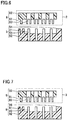
Fig. 6 ,connection box 2 may include a connection-box-side connector 6 (first connector 6). Connection-box-side connector 6 may include, for example, afirst engagement portion 61, a first insulatingsupport portion 62, and afirst electrode 63. First insulatingsupport portion 62 supportsfirst electrode 63.First electrode 63 is, for example, recessed.First engagement portion 61 is provided in first insulatingsupport portion 62.First engagement portion 61 is, for example, projecting. Connection-box-side connector 6 can be connected to power-cable-side connector 5. - As shown in
Fig. 6 , power-cable-side connector 5 includes, for example, a second engagement portion 51, a second insulatingsupport portion 52, asecond electrode 53, and a second projectingsurface 54. Second insulatingsupport portion 52 supportssecond electrode 53.Second electrode 53 is, for example, in a rod shape.Second electrode 53 is connected to the plurality ofpower cables 72. Second engagement portion 51 is provided in second insulatingsupport portion 52. Second engagement portion 51 is, for example, recessed. Second engagement portion 51 can be engaged withfirst engagement portion 61.Second electrode 53 can be engaged withfirst electrode 63. - Connection-box-
side connector 6 and power-cable-side connector 5 may be constructed to prevent connection between them in wrong electrode arrangement. As shown inFig. 6 , in correct electrode arrangement, each offirst engagement portion 61 and second engagement portion 51 is arranged on the left inFig. 6 . In this case,first engagement portion 61 is engaged with second engagement portion 51. Similarly,first electrode 63 is engaged withsecond electrode 53. In wrong electrode arrangement,first engagement portion 61 is arranged on the right inFig. 6 and second engagement portion 51 is arranged on the left inFig. 6 . When an attempt to attach power-cable-side connector 5 to connection-box-side connector 6 is made in this case,first engagement portion 61 abuts on second projectingsurface 54 of second insulatingsupport portion 52 so thatfirst electrode 63 is prevented from being engaged withsecond electrode 53. The construction of connection-box-side connector 6 and power-cable-side connector 5 shown inFig. 6 is merely by way of example. Connection-box-side connector 6 and power-cable-side connector 5 according to the present embodiment are not limited to the construction shown inFig. 6 . - As shown in
Fig. 7 ,control box 3 may include a control-box-side connector 8. Control-box-side connector 8 includes, for example, athird engagement portion 81, a thirdinsulating support portion 82, and a third electrode 83. Third insulatingsupport portion 82 supports third electrode 83. Third electrode 83 is, for example, recessed.Third engagement portion 81 is provided in third insulatingsupport portion 82.Third engagement portion 81 is, for example, projecting. Control-box-side connector 8 can be connected to control-cable-side connector 9. - As shown in
Fig. 7 , control-cable-side connector 9 includes, for example, afourth engagement portion 91, a fourth insulating support portion 92, a fourth electrode 93, and a fourth projectingsurface 94. Fourth insulating support portion 92 supports fourth electrode 93. Fourth electrode 93 is, for example, in a rod shape. Fourth electrode 93 is connected to the plurality ofcontrol cables 73.Fourth engagement portion 91 is provided in fourth insulating support portion 92.Fourth engagement portion 91 is, for example, recessed.Fourth engagement portion 91 can be engaged withthird engagement portion 81. Fourth electrode 93 can be engaged with third electrode 83. - Control-box-
side connector 8 and control-cable-side connector 9 may be constructed to prevent connection between them in wrong electrode arrangement. As shown inFig. 7 , in correct electrode arrangement, each ofthird engagement portion 81 andfourth engagement portion 91 is arranged on the left. In this case,third engagement portion 81 is engaged withfourth engagement portion 91. Similarly, third electrode 83 is engaged with fourth electrode 92. In wrong electrode arrangement,third engagement portion 81 is arranged on the right inFig. 7 andfourth engagement portion 91 is arranged on the left inFig. 6 . When an attempt to attach control-cable-side connector 9 to control-box-side connector 8 is made in this case,third engagement portion 81 abuts on fourth projectingsurface 94 of fourth insulating support portion 92 so that engagement of third electrode 83 with fourth electrode 93 is prevented. The construction of control-box-side connector 8 and control-cable-side connector 9 shown inFig. 7 is merely by way of example. Control-box-side connector 8 and control-cable-side connector 9 according to the present embodiment are not limited to the construction shown inFig. 7 . - An operation of concentrator
photovoltaic apparatus 100 according to the present embodiment will now be described. - Concentrator
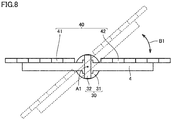
photovoltaic panel 40 is constructed, for example, to be rotatable around two axes. Specifically, as shown inFig. 8 , concentratorphotovoltaic panel 40 is constructed to be rotatable around a first rotation axis A1 along the direction of extension ofpedestal 1. Specifically,azimuth driving unit 31 rotates around first rotation axis A1 upon receiving a command fromcontrol box 3 through thirdcontrol cable portion 23.Elevation driving unit 32 arranged onazimuth driving unit 31 thus rotates around first rotation axis A1 together withshaft 4. Therefore, concentratorphotovoltaic panel 40 attached toshaft 4 rotates around first rotation axis A1. Concentratorphotovoltaic panel 40 thus rotates in an azimuth direction B1. - As shown in
Fig. 9 , concentratorphotovoltaic panel 40 is constructed to be rotatable around a second rotation axis A2 along the direction of extension ofshaft 4. Second rotation axis A2 is orthogonal to first rotation axis A1. Specifically,elevation driving unit 32 rotates around second rotation axis A2 upon receiving a command fromcontrol box 3 through fourthcontrol cable portion 24.Shaft 4 attached toelevation driving unit 32 thus rotates around second rotation axis A2. Therefore, concentratorphotovoltaic panel 40 attached toshaft 4 rotates around second rotation axis A2. Concentratorphotovoltaic panel 40 thus rotates in an elevation direction B2. Concentratorphotovoltaic panel 40 can track movement of the sun, for example, by using a sun sensor. Specifically, concentratorphotovoltaic panel 40 is movable with movement of the sun so as to maintain an angle at which the panel faces the sun. - A method of wiring in concentrator
photovoltaic apparatus 100 according to the present embodiment will now be described. - Initially, power-
purpose wire harness 10 and control-purpose wire harness 20 are prepared. Specifically, power-purpose wire harness 10 is prepared by tying the plurality ofpower cables 72 in bundle by using power-purpose insulating tube 71. Similarly, control-purpose wire harness 20 is prepared by tying the plurality ofcontrol cables 73 in bundle by using control-purpose insulating tube 29. Each of power-purpose wire harness 10 and control-purpose wire harness 20 is prepared, for example, in advance in factories, rather than being prepared at a site of installation of concentratorphotovoltaic apparatus 100. - Then, power-
purpose wire harness 10 is attached to concentratorphotovoltaic panel 40. Specifically, first-panel-portion connector 15 of power-purpose wire harness 10 is connected tofirst panel portion 41 of concentratorphotovoltaic panel 40. Similarly, second-panel-portion connector 17 of power-purpose wire harness 10 is connected tosecond panel portion 42 of concentratorphotovoltaic panel 40. Control-purpose wire harness 20 is attached to drivingunit 30. Specifically, thirdcontrol cable portion 23 of control-purpose wire harness 20 is connected, for example, to an azimuth control motor. Similarly, fourthcontrol cable portion 24 of control-purpose wire harness 20 is connected, for example, to an elevation control motor. Other control cables are each connected to a prescribed sensor or switch. - Then, power-
purpose wire harness 10 is attached toconnection box 2. Specifically, power-cable-side connector 5 of power-purpose wire harness 10 is connected to connection-box-side connector 6 ofconnection box 2. Similarly, control-purpose wire harness 20 is attached to controlbox 3. Specifically, control-cable-side connector 9 of control-purpose wire harness 20 is connected to control-box-side connector 8 ofcontrol box 3. As set forth above, works for wiring the plurality ofpower cables 72 and the plurality ofcontrol cables 73 are completed. - In wiring of cables at a site, cables and cable supplementary materials are always sufficiently procured. Therefore, there may be excessive cables and cable supplementary materials left after completion of wiring works. Quality of wiring works may be varied due to variation in skills of workers of a constructor at the site. Significant increase in number of cables due to a larger scale of facilities leads to complicated wiring works. In this case, time required for wiring works significantly increases and wrong wiring is also highly likely. By preparing the plurality of
power cables 72 and the plurality ofcontrol cables 73 as harnesses as above, cost for components can be reduced. Furthermore, variation in quality of wiring works can be lessened. In addition, time for wiring works can significantly be reduced. Moreover, possibility of wrong wiring can be lessened. By additionally providing an identification indication at the end of each cable, possibility of wrong wiring can further be lowered. - Functions and effects of concentrator
photovoltaic apparatus 100 according to the present embodiment will now be described. - In concentrator
photovoltaic apparatus 100 according to the present embodiment, power-purpose wire harness 10 includes a plurality ofpower cables 72 through which electric power generated by concentratorphotovoltaic panel 40 can be taken out and power-purpose insulating tube 71 that ties the plurality ofpower cables 72 in bundle. By tyingpower cables 72 in bundle by using power-purpose insulating tube 71, insulation performance ofpower cable 72 can be enhanced. Consequently, reliability ofpower cable 72 can be improved. By tying the plurality ofpower cables 72 in bundle by using power-purpose insulating tube 71 to make a harness, efficiency in works for attachment ofpower cable 72 can be improved. - Concentrator
photovoltaic apparatus 100 according to the present embodiment further includes drivingunit 30 that drives concentratorphotovoltaic panel 40 and control-purpose wire harness 20 connected to drivingunit 30. Control-purpose wire harness 20 includes a plurality ofcontrol cables 73 connected to drivingunit 30 and control-purpose insulating tube 29 that ties the plurality ofcontrol cables 73 in bundle. A voltage applied to each of the plurality ofpower cables 72 is higher than a voltage applied to each of the plurality ofcontrol cables 73. By tying the plurality ofcontrol cables 73 in bundle by using control-purpose insulating tube 29 to make a harness, efficiency in works for attachment of the control cable can be improved. Furthermore, a power supply different in type can be separated. - Concentrator
photovoltaic apparatus 100 according to the present embodiment further includespedestal 1 that supports drivingunit 30. Each of power-purpose wire harness 10 and control-purpose wire harness 20 is provided along the direction of extension ofpedestal 1. Thus, each of power-purpose wire harness 10 and control-purpose wire harness 20 can be prevented from interfering the concentrator photovoltaic panel in rotation of the concentrator photovoltaic panel. - Concentrator
photovoltaic apparatus 100 according to the present embodiment further includesconnection box 2 attached topedestal 1.Connection box 2 includesfirst connector 6. Power-purpose wire harness 10 includessecond connector 5 that can be connected tofirst connector 6. Efficiency in attachment of power-purpose wire harness 10 toconnection box 2 can thus be improved. - In concentrator
photovoltaic apparatus 100 according to the present embodiment, the plurality ofpower cables 72 include a plurality of firstpower cable portions 14 connected tofirst panel portion 41 and a plurality of secondpower cable portions 16 connected tosecond panel portion 42. Power-purpose insulating tube 71 includesfirst region 11 that surrounds both of the plurality of firstpower cable portions 14 and the plurality of secondpower cable portions 16 andsecond region 12 that does not surround the plurality of firstpower cable portions 14 but surrounds the plurality of secondpower cable portions 16. The plurality ofpower cables 72 can thus be branched into the plurality of firstpower cable portions 14 connected tofirst panel portion 41 and the plurality of secondpower cable portions 16 connected tosecond panel portion 42. - In concentrator
photovoltaic apparatus 100 according to the present embodiment, concentratorphotovoltaic panel 40 includesfirst panel portion 41 andsecond panel portion 42 provided at a distance from each other. Power-purpose wire harness 10 includes first-panel-portion connector 15 connected tofirst panel portion 41 and second-panel-portion connector 17 connected tosecond panel portion 42. First-panel-portion connector 15 is different in shape from second-panel-portion connector 17. Wrong connection of first-panel-portion connector 15 tosecond panel portion 42 can thus be prevented. Similarly, wrong connection of second-panel-portion connector 17 tofirst panel portion 41 can be prevented. Consequently, efficiency in attachment ofpower cable 72 can further be improved. - In concentrator
photovoltaic apparatus 100 according to the present embodiment, power-purpose insulating tube 71 is a corrugated tube. Since the corrugated tube is high in bendability, a degree of freedom in wiring can be enhanced. - In concentrator
photovoltaic apparatus 100 according to the present embodiment, power-purpose insulating tube 71 is composed of amaterial containing nylon 12.Nylon 12 is weather resistant to ultraviolet rays. Therefore, even though concentratorphotovoltaic apparatus 100 is installed at a location large in amount of solar radiation such as a desert, deterioration of power-purpose insulating tube 71 can be suppressed. - It should be understood that the embodiment disclosed herein is illustrative and non-restrictive in every respect. The scope of the present invention is defined by the terms of the claims rather than the description above and is intended to include any modifications within the scope and meaning equivalent to the terms of the claims.
- 1 pedestal; 1a bottom surface; 2 connection box; 3 control box; 4 shaft; 5 second connector (power-cable-side connector); 6 first connector (connection-box-side connector); 7 connection portion; 8 control-box-side connector; 9 control-cable-side connector; 10 power-purpose wire harness; 11 first region; 12 second region; 13 third region; 14 first power cable portion; 14a second negative-side power cable portion; 14b second positive-side power cable portion; 14c first negative-side power cable portion; 14d first positive-side power cable portion; 15 first-panel-portion connector; 15a second negative-side connector portion; 15b second positive-side connector portion; 15c first negative-side connector portion; 15d first positive-side connector portion; 16 second power cable portion; 16a fourth positive-side power cable portion; 16b fourth negative-side power cable portion; 16c third positive-side power cable portion; 16d third negative-side power cable portion; 17 second-panel-portion connector; 17a fourth positive-side connector portion; 17b fourth negative-side connector portion; 17c third positive-side connector portion; 17d third negative-side connector portion; 18 grounding line; 19 tape; 20 control-purpose wire harness; 21 first control cable portion; 22 second control cable portion; 23 third control cable portion; 24 fourth control cable portion; 25 fifth control cable portion; 26 sixth control cable portion; 27 seventh control cable portion; 28 eighth control cable portion; 29 control-purpose insulating tube; 30 driving unit; 31 azimuth driving unit; 32 elevation driving unit; 33 metal line; 34 insulating cover; 40 concentrator photovoltaic panel; 41 first panel portion; 42 second panel portion; 51 second engagement portion; 52 second insulating support portion; 53 second electrode; 54 second projecting surface; 61 first engagement portion; 62 first insulating support portion; 63 first electrode; 71 power-purpose insulating tube; 72 power cable; 73 control cable; 81 third engagement portion; 82 third insulating support portion; 83 third electrode; 91 fourth engagement portion; 92 fourth insulating support portion; 93 fourth electrode; 94 fourth projecting surface; 100 concentrator photovoltaic apparatus; A1 first rotation axis; A2 second rotation axis; B1 azimuth direction; B2 elevation direction
Claims (8)
- A concentrator photovoltaic apparatus comprising:a concentrator photovoltaic panel; anda power-purpose wire harness connected to the concentrator photovoltaic panel,the power-purpose wire harness includinga plurality of power cables through which electric power generated by the concentrator photovoltaic panel can be taken out, anda power-purpose insulating tube that ties the plurality of power cables in bundle.
- The concentrator photovoltaic apparatus according to claim 1, further comprising:a driving unit that drives the concentrator photovoltaic panel; anda control-purpose wire harness connected to the driving unit, whereinthe control-purpose wire harness includes a plurality of control cables connected to the driving unit and a control-purpose insulating tube that ties the plurality of control cables in bundle, anda voltage applied to each of the plurality of power cables is higher than a voltage applied to each of the plurality of control cables.
- The concentrator photovoltaic apparatus according to claim 2, further comprising:a pedestal that supports the driving unit, whereineach of the power-purpose wire harness and the control-purpose wire harness is provided along a direction of extension of the pedestal.
- The concentrator photovoltaic apparatus according to claim 3, further comprising:a connection box attached to the pedestal, whereinthe connection box includes a first connector, andthe power-purpose wire harness includes a second connector that can be connected to the first connector.
- The concentrator photovoltaic apparatus according to any one of claims 1 to 4, wherein
the concentrator photovoltaic panel includes a first panel portion and a second panel portion provided at a distance from each other,
the power-purpose wire harness includes a first-panel-portion connector connected to the first panel portion and a second-panel-portion connector connected to the second panel portion, and
the first-panel-portion connector is different in shape from the second-panel-portion connector. - The concentrator photovoltaic apparatus according to claim 5, wherein
the plurality of power cables include a plurality of first power cable portions connected to the first panel portion and a plurality of second power cable portions connected to the second panel portion, and
the power-purpose insulating tube includes a first region that surrounds both of the plurality of first power cable portions and the plurality of second power cable portions and a second region that does not surround the plurality of first power cable portions but surrounds the plurality of second power cable portions. - The concentrator photovoltaic apparatus according to any one of claims 1 to 6, wherein
the power-purpose insulating tube is a corrugated tube. - The concentrator photovoltaic apparatus according to any one of claims 1 to 7, wherein
the power-purpose insulating tube is composed of a material containing nylon 12.
Applications Claiming Priority (2)
| Application Number | Priority Date | Filing Date | Title |
|---|---|---|---|
| JP2017225981 | 2017-11-24 | ||
| PCT/JP2018/039138 WO2019102760A1 (en) | 2017-11-24 | 2018-10-22 | Concentrating solar power generation device |
Publications (2)
| Publication Number | Publication Date |
|---|---|
| EP3716473A1 true EP3716473A1 (en) | 2020-09-30 |
| EP3716473A4 EP3716473A4 (en) | 2021-08-11 |
Family
ID=66631469
Family Applications (1)
| Application Number | Title | Priority Date | Filing Date |
|---|---|---|---|
| EP18880392.8A Withdrawn EP3716473A4 (en) | 2017-11-24 | 2018-10-22 | CONCENTRATING SOLAR ENERGY GENERATING DEVICE |
Country Status (8)
| Country | Link |
|---|---|
| US (1) | US20200395887A1 (en) |
| EP (1) | EP3716473A4 (en) |
| JP (1) | JPWO2019102760A1 (en) |
| CN (1) | CN111373654A (en) |
| AU (1) | AU2018372296A1 (en) |
| MA (1) | MA50883A (en) |
| TW (1) | TW201926830A (en) |
| WO (1) | WO2019102760A1 (en) |
Families Citing this family (1)
| Publication number | Priority date | Publication date | Assignee | Title |
|---|---|---|---|---|
| JP2023034240A (en) * | 2021-08-30 | 2023-03-13 | 株式会社 Fd | Photovoltaic power generation system |
Family Cites Families (18)
| Publication number | Priority date | Publication date | Assignee | Title |
|---|---|---|---|---|
| NO153511C (en) * | 1983-08-25 | 1986-04-02 | Standard Tel Kabelfab As | FIRE AND OIL RESISTANT CABLE. |
| JP2894144B2 (en) * | 1993-03-18 | 1999-05-24 | 住友電装株式会社 | Wire harness waterproof structure |
| JPH09213137A (en) * | 1996-01-30 | 1997-08-15 | Showa Electric Wire & Cable Co Ltd | Termite-proof wires and cables |
| JP3406197B2 (en) | 1997-09-04 | 2003-05-12 | 積水化学工業株式会社 | Building wrapping joints and cable wiring structure of photovoltaic power generation system |
| JPH11166304A (en) * | 1997-12-04 | 1999-06-22 | Sanko Metal Ind Co Ltd | Roofing materials with solar cells |
| JP2000057854A (en) * | 1998-08-04 | 2000-02-25 | Sumitomo Wiring Syst Ltd | Wire bundle |
| JP5434748B2 (en) * | 2009-12-24 | 2014-03-05 | 日立金属株式会社 | Conductive path for vehicles |
| US8937249B2 (en) * | 2010-03-01 | 2015-01-20 | Shoals Technologies Group, Llc | Solar energy wire harness with in-line fuses |
| JP2013073883A (en) * | 2011-09-29 | 2013-04-22 | Yazaki Energy System Corp | Cable unit and method for manufacturing cable unit |
| JP6070376B2 (en) * | 2013-04-03 | 2017-02-01 | 住友電気工業株式会社 | Control device for solar tracking solar power generation system and solar tracking solar power generation system |
| US20150263668A1 (en) * | 2014-03-14 | 2015-09-17 | Jon Dennis Sader | System and method for a plug and play electrical wiring harness for the connection of a solar system to existing electrical wiring of a building |
| WO2016144890A1 (en) * | 2015-03-06 | 2016-09-15 | Instant Solar LLC | Portable solar power generation devices for permanent or temporary installations and methods thereof |
| JP2017005864A (en) * | 2015-06-10 | 2017-01-05 | 住友電気工業株式会社 | SOLAR POWER GENERATOR, SOLAR POWER GENERATOR INSTALLATION METHOD, AND SOLAR POWER GENERATOR OPERATION METHOD |
| JP2017011813A (en) * | 2015-06-18 | 2017-01-12 | 住友電装株式会社 | Branch part protection structure for wiring harness |
| ES1144186Y (en) * | 2015-09-14 | 2015-12-29 | Soltec Energias Renovables Sl | SOLAR ENERGY COLLECTION DEVICE |
| CN205647412U (en) * | 2016-04-11 | 2016-10-12 | 苏州金山太阳能科技有限公司 | Traditional thread binding putting of cable collection |
| JP6662210B2 (en) | 2016-06-20 | 2020-03-11 | 日本軽金属株式会社 | Joining method |
| JP6292266B2 (en) * | 2016-09-07 | 2018-03-14 | 住友電気工業株式会社 | Concentrating solar power generation panel and concentrating solar power generation device |
-
2018
- 2018-10-22 MA MA050883A patent/MA50883A/en unknown
- 2018-10-22 US US16/764,334 patent/US20200395887A1/en not_active Abandoned
- 2018-10-22 CN CN201880075033.9A patent/CN111373654A/en active Pending
- 2018-10-22 JP JP2019556138A patent/JPWO2019102760A1/en active Pending
- 2018-10-22 EP EP18880392.8A patent/EP3716473A4/en not_active Withdrawn
- 2018-10-22 WO PCT/JP2018/039138 patent/WO2019102760A1/en not_active Ceased
- 2018-10-22 AU AU2018372296A patent/AU2018372296A1/en not_active Abandoned
- 2018-11-02 TW TW107138933A patent/TW201926830A/en unknown
Also Published As
| Publication number | Publication date |
|---|---|
| EP3716473A4 (en) | 2021-08-11 |
| CN111373654A (en) | 2020-07-03 |
| WO2019102760A1 (en) | 2019-05-31 |
| TW201926830A (en) | 2019-07-01 |
| AU2018372296A1 (en) | 2020-06-11 |
| MA50883A (en) | 2020-09-30 |
| US20200395887A1 (en) | 2020-12-17 |
| JPWO2019102760A1 (en) | 2020-12-03 |
Similar Documents
| Publication | Publication Date | Title |
|---|---|---|
| US12015376B2 (en) | Lead assembly for connecting solar panel arrays to inverter | |
| JP4279145B2 (en) | Wind energy plant with current bus | |
| US8512057B2 (en) | Device comprising rigid connecting bars for the conducting connection of first to second busbars | |
| KR101303402B1 (en) | Wind energy system comprising busbars | |
| EP2610878A1 (en) | Wire harness | |
| US10778140B2 (en) | Device for capturing solar energy | |
| US10812015B2 (en) | Micro-inverter assembly for use in a photovoltaic system and method of making same | |
| US10570891B2 (en) | Busbar system | |
| JP3326207B2 (en) | Solar cell module | |
| KR20230019241A (en) | Lightning bypass system | |
| US20200395887A1 (en) | Concentrator photovoltaic apparatus | |
| JP2010268595A (en) | Wind power generator and power cable laying method to wind-power generator | |
| US20180219509A1 (en) | Easy to install flexible photovoltaic modules | |
| US10958212B2 (en) | Electrical connection support assembly and method of use | |
| JPWO2019082589A1 (en) | Solar power system | |
| US20150103497A1 (en) | Photovoltaic system with improved ac connections and method of making same | |
| JP4798956B2 (en) | Solar cell module and solar power generation apparatus using the same | |
| CN103346183B (en) | Electrical connection assembly of building photovoltaic component | |
| CN118899118A (en) | Photovoltaic cable for photovoltaic power station | |
| KR20130003292U (en) | Cylinder connected to the motor directly | |
| WO2024072830A1 (en) | Lead assembly with an integral fuse | |
| BR102020001381A2 (en) | PHOTOVOLTAIC MODULE WITH PROTECTIVE REGION AND PHOTOVOLTAIC MODULE PROTECTION METHOD | |
| WO2019225309A1 (en) | Solar power generation system | |
| JP2006165170A (en) | Solar power system |
Legal Events
| Date | Code | Title | Description |
|---|---|---|---|
| STAA | Information on the status of an ep patent application or granted ep patent |
Free format text: STATUS: THE INTERNATIONAL PUBLICATION HAS BEEN MADE |
|
| PUAI | Public reference made under article 153(3) epc to a published international application that has entered the european phase |
Free format text: ORIGINAL CODE: 0009012 |
|
| STAA | Information on the status of an ep patent application or granted ep patent |
Free format text: STATUS: REQUEST FOR EXAMINATION WAS MADE |
|
| 17P | Request for examination filed |
Effective date: 20200513 |
|
| AK | Designated contracting states |
Kind code of ref document: A1 Designated state(s): AL AT BE BG CH CY CZ DE DK EE ES FI FR GB GR HR HU IE IS IT LI LT LU LV MC MK MT NL NO PL PT RO RS SE SI SK SM TR |
|
| AX | Request for extension of the european patent |
Extension state: BA ME |
|
| DAX | Request for extension of the european patent (deleted) | ||
| RAV | Requested validation state of the european patent: fee paid |
Extension state: MA Effective date: 20200513 |
|
| A4 | Supplementary search report drawn up and despatched |
Effective date: 20210708 |
|
| RIC1 | Information provided on ipc code assigned before grant |
Ipc: H02S 40/34 20140101AFI20210702BHEP Ipc: H02G 3/04 20060101ALI20210702BHEP Ipc: H02G 3/30 20060101ALI20210702BHEP Ipc: H02S 20/10 20140101ALI20210702BHEP Ipc: H02S 20/32 20140101ALI20210702BHEP |
|
| STAA | Information on the status of an ep patent application or granted ep patent |
Free format text: STATUS: THE APPLICATION HAS BEEN WITHDRAWN |
|
| 18W | Application withdrawn |
Effective date: 20210930 |