EP3716354A1 - Power supply unit mounting structure and surveying instrument - Google Patents
Power supply unit mounting structure and surveying instrument Download PDFInfo
- Publication number
- EP3716354A1 EP3716354A1 EP20165584.2A EP20165584A EP3716354A1 EP 3716354 A1 EP3716354 A1 EP 3716354A1 EP 20165584 A EP20165584 A EP 20165584A EP 3716354 A1 EP3716354 A1 EP 3716354A1
- Authority
- EP
- European Patent Office
- Prior art keywords
- lock
- power supply
- supply unit
- plate
- cam
- Prior art date
- Legal status (The legal status is an assumption and is not a legal conclusion. Google has not performed a legal analysis and makes no representation as to the accuracy of the status listed.)
- Withdrawn
Links
Images


Classifications
-
- G—PHYSICS
- G01—MEASURING; TESTING
- G01C—MEASURING DISTANCES, LEVELS OR BEARINGS; SURVEYING; NAVIGATION; GYROSCOPIC INSTRUMENTS; PHOTOGRAMMETRY OR VIDEOGRAMMETRY
- G01C15/00—Surveying instruments or accessories not provided for in groups G01C1/00 - G01C13/00
-
- H—ELECTRICITY
- H01—ELECTRIC ELEMENTS
- H01M—PROCESSES OR MEANS, e.g. BATTERIES, FOR THE DIRECT CONVERSION OF CHEMICAL ENERGY INTO ELECTRICAL ENERGY
- H01M50/00—Constructional details or processes of manufacture of the non-active parts of electrochemical cells other than fuel cells, e.g. hybrid cells
- H01M50/20—Mountings; Secondary casings or frames; Racks, modules or packs; Suspension devices; Shock absorbers; Transport or carrying devices; Holders
- H01M50/233—Mountings; Secondary casings or frames; Racks, modules or packs; Suspension devices; Shock absorbers; Transport or carrying devices; Holders characterised by physical properties of casings or racks, e.g. dimensions
- H01M50/24—Mountings; Secondary casings or frames; Racks, modules or packs; Suspension devices; Shock absorbers; Transport or carrying devices; Holders characterised by physical properties of casings or racks, e.g. dimensions adapted for protecting batteries from their environment, e.g. from corrosion
-
- H—ELECTRICITY
- H01—ELECTRIC ELEMENTS
- H01M—PROCESSES OR MEANS, e.g. BATTERIES, FOR THE DIRECT CONVERSION OF CHEMICAL ENERGY INTO ELECTRICAL ENERGY
- H01M50/00—Constructional details or processes of manufacture of the non-active parts of electrochemical cells other than fuel cells, e.g. hybrid cells
- H01M50/20—Mountings; Secondary casings or frames; Racks, modules or packs; Suspension devices; Shock absorbers; Transport or carrying devices; Holders
- H01M50/244—Secondary casings; Racks; Suspension devices; Carrying devices; Holders characterised by their mounting method
-
- H—ELECTRICITY
- H01—ELECTRIC ELEMENTS
- H01M—PROCESSES OR MEANS, e.g. BATTERIES, FOR THE DIRECT CONVERSION OF CHEMICAL ENERGY INTO ELECTRICAL ENERGY
- H01M50/00—Constructional details or processes of manufacture of the non-active parts of electrochemical cells other than fuel cells, e.g. hybrid cells
- H01M50/20—Mountings; Secondary casings or frames; Racks, modules or packs; Suspension devices; Shock absorbers; Transport or carrying devices; Holders
- H01M50/247—Mountings; Secondary casings or frames; Racks, modules or packs; Suspension devices; Shock absorbers; Transport or carrying devices; Holders specially adapted for portable devices, e.g. mobile phones, computers, hand tools or pacemakers
-
- H—ELECTRICITY
- H01—ELECTRIC ELEMENTS
- H01M—PROCESSES OR MEANS, e.g. BATTERIES, FOR THE DIRECT CONVERSION OF CHEMICAL ENERGY INTO ELECTRICAL ENERGY
- H01M50/00—Constructional details or processes of manufacture of the non-active parts of electrochemical cells other than fuel cells, e.g. hybrid cells
- H01M50/20—Mountings; Secondary casings or frames; Racks, modules or packs; Suspension devices; Shock absorbers; Transport or carrying devices; Holders
- H01M50/262—Mountings; Secondary casings or frames; Racks, modules or packs; Suspension devices; Shock absorbers; Transport or carrying devices; Holders with fastening means, e.g. locks
- H01M50/264—Mountings; Secondary casings or frames; Racks, modules or packs; Suspension devices; Shock absorbers; Transport or carrying devices; Holders with fastening means, e.g. locks for cells or batteries, e.g. straps, tie rods or peripheral frames
-
- H—ELECTRICITY
- H01—ELECTRIC ELEMENTS
- H01M—PROCESSES OR MEANS, e.g. BATTERIES, FOR THE DIRECT CONVERSION OF CHEMICAL ENERGY INTO ELECTRICAL ENERGY
- H01M2220/00—Batteries for particular applications
- H01M2220/30—Batteries in portable systems, e.g. mobile phone, laptop
-
- Y—GENERAL TAGGING OF NEW TECHNOLOGICAL DEVELOPMENTS; GENERAL TAGGING OF CROSS-SECTIONAL TECHNOLOGIES SPANNING OVER SEVERAL SECTIONS OF THE IPC; TECHNICAL SUBJECTS COVERED BY FORMER USPC CROSS-REFERENCE ART COLLECTIONS [XRACs] AND DIGESTS
- Y02—TECHNOLOGIES OR APPLICATIONS FOR MITIGATION OR ADAPTATION AGAINST CLIMATE CHANGE
- Y02E—REDUCTION OF GREENHOUSE GAS [GHG] EMISSIONS, RELATED TO ENERGY GENERATION, TRANSMISSION OR DISTRIBUTION
- Y02E60/00—Enabling technologies; Technologies with a potential or indirect contribution to GHG emissions mitigation
- Y02E60/10—Energy storage using batteries
Definitions
- the present invention relates to a power supply unit mounting structure which enables a power supply unit to be easily attached and detached to and from a surveying instrument.
- a surveying instrument is used in a location or an environment where a commercial power supply is unavailable such as in the field and the like, the instrument itself is provided with a power supply. Further, a rechargeable battery is usually used as a power supply, and the battery is replaceable with respect to the surveying instrument.
- the surveying instrument is used in the field, a waterproof property is required, and the battery is desired to be easily replaceable.
- the power supply unit comprises a flange part and a lock module provided on the flange part
- the lock module comprises a lock knob which is rotatable and restrained from moving in the axial direction, a lock plate provided at a tip of a rotation shaft of the lock knob, and a cam mechanism configured to displace the lock plate in an axial direction by restraining a rotation of the lock plate
- the lock plate includes engagement holes which are engageable with the lock pins, and wherein the lock pins are inserted into the engagement holes by inserting the power supply unit into the power supply unit storage, and by rotating the lock knob, the lock plate is rotated and the lock
- the cam mechanism comprises a cam plate which is rotatably and slidably provided to the rotation shaft, a V-groove formed on the cam plate, a cam pin provided at a tip portion of the rotation shaft in such a manner that the cam pin is orthogonal to a rotation axis and which is fittable and removable with respect to the V-groove, and an energizing means which energizes the cam plate in such a manner that the cam plate is pressed against the cam pin, and wherein the lock plate is fixed to the cam plate.
- a surveying instrument comprises a surveying instrument main body which has a power supply unit storage, a power supply unit which is inserted into the power supply unit storage, and the power supply unit mounting structure.
- the power supply unit mounting structure for mounting a power supply unit which is inserted into a power supply unit storage of a surveying instrument main body comprises two stepped lock pins protruded adjacent to an opening of the power supply unit storage and a seal provided in such a manner that the seal surrounds the opening
- the power supply unit comprises a flange part and a lock module provided on the flange part
- the lock module comprises a lock knob which is rotatable and is restrained from moving in an axial direction, a lock plate provided at a tip of a rotation shaft of the lock knob, and a cam mechanism configured to displace the lock plate in an axial direction by restraining a rotation of the lock plate
- the lock plate includes engagement holes which are engageable with the lock pins, and wherein the lock pins are inserted into the engagement holes by inserting the power supply unit into the power supply unit storage, and by rotating the lock knob, the lock plate is rotated and the lock pins engage with the engagement holes
- FIG.1 is a perspective view of a surveying instrument 1 according to the present embodiment as viewed from the rear
- FIG.2A and FIG.2B are perspective views of a battery holder 4 as viewed from the front.
- a reference numeral 2 denotes a surveying instrument main body
- a reference numeral 3 denotes a power supply unit
- a reference numeral 4 denotes the battery holder
- a reference numeral 5 denotes a battery.
- the surveying instrument 1 mainly has the surveying instrument main body 2 and the power supply unit 3.
- the surveying instrument main body 2 has a power supply unit storage 7 which is opened to the rear.
- the power supply unit 3 is inserted into the power supply unit storage 7 from a horizontal direction.
- An abutting surface 8 receding inward from a rear end surface of the surveying instrument main body 2 is formed around an opening of the power supply unit storage 7.
- Lock pins 11 are protruded at two positions (left-and-right two positions in the drawing) adjacent to the opening on a flange surface 10 receding inward from the abutting surface 8.
- the power supply unit 3 is made up by the battery holder 4 and the battery 5, and the battery 5 is mounted on the battery holder 4 from above.
- the battery holder 4 consists of a flange part 13 and a battery case 14 which extends frontward. A shallow bottom concave portion is formed to the battery case 14, and the battery 5 is fitted in the concave portion from above. Electric contacts (not shown) are formed on a front end surface (in the drawing, an end surface on the surveying instrument main body 2 side) of the battery 5.
- the flange part 13 abuts on the abutting surface 8 in such a manner that a receding part of the abutting surface 8 is filled. Further, the flange part 13 has a lid 12 which closes the opening of the power supply unit storage 7, and a lock module 16 (to be described later) is provided on the flange part 13.
- the lock module 16 has a lock knob 15, and the lock knob 15 is rotatable in the flange part 13 and is restrained from moving in an axial direction.
- the lid 12 is provided with a seal 9, and the seal 9 can abut on a rim of the opening. It is to be noted that the seal 9 may be provided on the abutting surface 8 side.
- the lid 12 By inserting the power supply unit 3 into the power supply unit storage 7, the lid 12 closes the opening, and the seal 9 abuts on the rim of the opening.
- the electric contacts of the battery 5 are joined with electric contacts on the surveying instrument main body 2 side.
- the lock knob 15 In a state where the power supply unit 3 is inserted, when the lock knob 15 is rotated, the lock module 16 engages with the lock pins 11. Thereby, the power supply unit 3 is fastened to the surveying instrument main body 2, the seal 9 closely adheres to the rim of the opening, and the opening is sealed liquid-tight.
- FIG.2A, FIG.2B , FIG.3 , FIG.4A, and FIG.4B A description will be given on the lock module 16 by referring to FIG.2A, FIG.2B , FIG.3 , FIG.4A, and FIG.4B .
- FIG.2A and FIG.2B are perspective views of the battery holder 4 as viewed from the front, where FIG.2A shows an opened state and FIG.2B shows a locked state.
- FIG.2A and FIG.2B the right side is determined to be the front, and the left side is determined to be the rear. It is to be noted that the battery 5 is omitted in the drawings.
- reference numerals 11 denote lock pins, and as shown in FIG.1 , the lock pins 11 are protruded on the abutting surface 8 of the surveying instrument main body 2.
- the lock module 16 has a lock plate 21 at a front surface position.
- the lock plate 21 is accommodated in a space between the abutting surface 8 and the flange surface 10, and the lock plate 21 is rotatable in the space.
- Engagement holes 22 in which the lock pins 11 can be fitted are formed at both end portions of the lock plate 21.
- Each of the engagement holes 22 has a keyhole shape in which a circular hole 22a is continuous with a long hole 22b. A diameter of the circular hole 22a is larger than a diameter of the long hole 22b.
- Each of the lock pins 11 has a stepped shape and is formed of a head portion 11a, a shaft portion 11b, and a screw portion 11c.
- a diameter of the head portion 11a is smaller than the diameter of the circular hole 22a and larger than the diameter of the long hole 22b.
- a diameter of the shaft portion 11b is smaller than the diameter of the long hole 22b.
- an axial length of the shaft portion 11b is slightly longer than a thickness of the lock plate 21.
- the screw portion 11c is available for fixing the lock pin 11 to the flange surface 10.
- each lock pin 11 In the opened state as shown in FIG.2A and also in a state where the battery holder 4 is inserted into the power supply unit storage 7, the axis of each lock pin 11 coincides with the center of each circular hole 22a. Further, in a state where the battery holder 4 is completely inserted into the power supply unit storage 7, each head portion 11a passes through each circular hole 22a, and each shaft portion 11b is loosely fitted in each circular hole 22a.
- FIG.3 A description will be further given on the lock module 16 by referring to FIG.3 , FIG.4A, and FIG.4B . It is to be noted that, in FIG.3 , to facilitate the understanding, only half of the lock plate 21 is shown.
- a discoid cam plate 25 is rotatably and slidably fitted on a rotation shaft 24 of the lock knob 15.
- the lock plate 21 is fixed to the cam plate 25 by bolts 27.
- a compression spring 26 as an energizing means is provided in a compressed state on a rear surface side (a rear side) of the cam plate 25, and the compression spring 26 biases the cam plate 25 toward a tip side (the right side in FIG.4A and FIG.4B ) of the rotation shaft 24. That is, the compression spring 26 biases the cam plate 25 in such a manner that the cam plate 25 is pressed against the lock pins 11.
- the energizing means may be a coned disc spring, an elastic rubber, a waved washer, or the like.
- a V-groove 28 is formed on the cam plate 25.
- a center line of the V-groove 28 runs through the axis of the rotation shaft 24 and is also orthogonal to the axis.
- the rotation shaft 24 passes through the cam plate 25, and a cam pin 29 which is orthogonal to the axis of the rotation shaft 24 is provided at a protruding tip portion of the rotation shaft 24. It is to be noted that an axial length of the cam pin 29 is sufficiently shorter than a length (a diameter) of the lock knob 15.
- An escape hole 31 is formed at a central portion of the lock plate 21 in such a manner that an interference with the rotation shaft 24 and the cam pin 29 is avoided.
- the escape hole 31 has a shape which allows a relative rotation at a predetermined angle among the lock plate 21, the rotation shaft 24, and the cam pin 29.
- the escape hole 31 has a shape in which a fan shape is point-symmetrically arranged with respect to the center of the rotation shaft 24, and a center angle of the fan shape has the predetermined angle of the relative rotation.
- FIG.4A shows an unlocked state of the lock module 16, and the cam pin 29 is fitted in the V-groove 28 by an energizing force of the compression spring 26. Therefore, in a state where the rotation of the cam plate 25 is not restrained, the cam plate 25 and the rotation shaft 24, that is, the lock knob 15, integrally rotate.
- the cam plate 25 When the cam pin 29 gets out of the V-groove 28 and runs up onto the flat surface of the cam plate 25, the cam plate 25 is displaced to the lock knob 15 side against the energizing force of the compression spring 26. Actually, the cam plate 25 is fixed to the lock plate 21, the lock plate 21 is restrained by the lock pins 11, and hence the cam plate 25, that is, the lock knob 15 is displaced to the surveying instrument main body 2 side. Since the displacement of the lock knob 15 is a displacement of the flange part 13, the seal 9 is compressed, and the sealing is performed.
- the cam plate 25fitted on the rotation shaft 24 so that it can rotate and be axially displaced, the V-groove 28 formed on the cam plate 25, the cam pin 29 capable of fitting in the V-groove 28, the compression spring 26, and the like make up a cam mechanism.
- the cam mechanism enables the cam pin 29 to get out of the V-groove 28 by restraining the rotation of the cam plate 25 and enables the cam plate 25 to move in the axial direction of the rotation shaft 24.
- the battery 5 is loaded onto the battery case 14 from above in such a manner that the power supply unit 3 is provided.
- the power supply unit 3 is inserted into the power supply unit storage 7 from the horizontal direction.
- the lock pins 11 are fitted in and pass through the circular holes 22a.
- the cam plate 25 and the lock plate 21 rotate integrally with the lock knob 15, the long holes 22b are fitted in the shaft portions 11b, and then the shaft portions 11b abut against end edges of the long holes 22b respectively, and the rotation of the lock plate 21 is restrained.
- the rotation of the cam plate 25 is also restrained.
- the lock knob 15 is displaced toward the lock plate 21, that is, the flange part 13 is displaced toward the abutting surface 8. Thereby, the lid 12 closes the opening, the seal 9 is compressed between the lid 12 and the abutting surface 8, and the sealing is performed between the lid 12 and the abutting surface 8.
- the rotation of the lock knob 15 in one direction completes the locking and the sealing of the power supply unit 3 with respect to the surveying instrument main body 2. It is to be noted that, in case of removing the power supply unit 3, by rotating the lock knob 15 in a reverse direction, it is possible to easily remove the power supply unit 3.
- the battery 5 can be easily mounted to the battery holder 4 with no obstruction, and the rotation of the lock knob 15 in one direction suffices to mount the battery holder 4 to the surveying instrument main body 2. As a result, it is possible to easily replace the battery 5 of the surveying instrument 1.
Landscapes
- Chemical Kinetics & Catalysis (AREA)
- General Chemical & Material Sciences (AREA)
- Electrochemistry (AREA)
- Chemical & Material Sciences (AREA)
- Engineering & Computer Science (AREA)
- Computer Hardware Design (AREA)
- Life Sciences & Earth Sciences (AREA)
- Biophysics (AREA)
- Physics & Mathematics (AREA)
- General Physics & Mathematics (AREA)
- Radar, Positioning & Navigation (AREA)
- Remote Sensing (AREA)
- Battery Mounting, Suspending (AREA)
Abstract
Description
- The present invention relates to a power supply unit mounting structure which enables a power supply unit to be easily attached and detached to and from a surveying instrument.
- Since a surveying instrument is used in a location or an environment where a commercial power supply is unavailable such as in the field and the like, the instrument itself is provided with a power supply. Further, a rechargeable battery is usually used as a power supply, and the battery is replaceable with respect to the surveying instrument.
- Further, since the surveying instrument is used in the field, a waterproof property is required, and the battery is desired to be easily replaceable.
- It is an object of the present invention to provide a power supply unit mounting structure which facilitates a replacement of a battery and has a waterproof structure, and a surveying instrument.
- To attain the object as described above, a power supply unit mounting structure according to the present invention for mounting a power supply unit which is inserted into a power supply unit storage of a surveying instrument main body comprises two stepped lock pins protruded adjacent to an opening of the power supply unit storage and a seal provided in such a manner that the seal surrounds the opening, wherein the power supply unit comprises a flange part and a lock module provided on the flange part, wherein the lock module comprises a lock knob which is rotatable and restrained from moving in the axial direction, a lock plate provided at a tip of a rotation shaft of the lock knob, and a cam mechanism configured to displace the lock plate in an axial direction by restraining a rotation of the lock plate, wherein, at both end portions, the lock plate includes engagement holes which are engageable with the lock pins, and wherein the lock pins are inserted into the engagement holes by inserting the power supply unit into the power supply unit storage, and by rotating the lock knob, the lock plate is rotated and the lock pins engage with the engagement holes, the rotation of the lock plate is restrained by the engagement holes, and by rotating the lock knob after restraining the rotation of the lock plate, the flange part is displaced to the opening side, the seal is pressed, and the opening is sealed.
- Further, in the power supply unit mounting structure according to a preferred embodiment, the cam mechanism comprises a cam plate which is rotatably and slidably provided to the rotation shaft, a V-groove formed on the cam plate, a cam pin provided at a tip portion of the rotation shaft in such a manner that the cam pin is orthogonal to a rotation axis and which is fittable and removable with respect to the V-groove, and an energizing means which energizes the cam plate in such a manner that the cam plate is pressed against the cam pin, and wherein the lock plate is fixed to the cam plate.
- Furthermore, a surveying instrument according to the present invention comprises a surveying instrument main body which has a power supply unit storage, a power supply unit which is inserted into the power supply unit storage, and the power supply unit mounting structure.
- According to the present invention, the power supply unit mounting structure for mounting a power supply unit which is inserted into a power supply unit storage of a surveying instrument main body comprises two stepped lock pins protruded adjacent to an opening of the power supply unit storage and a seal provided in such a manner that the seal surrounds the opening, wherein the power supply unit comprises a flange part and a lock module provided on the flange part, wherein the lock module comprises a lock knob which is rotatable and is restrained from moving in an axial direction, a lock plate provided at a tip of a rotation shaft of the lock knob, and a cam mechanism configured to displace the lock plate in an axial direction by restraining a rotation of the lock plate, wherein, at both end portions, the lock plate includes engagement holes which are engageable with the lock pins, and wherein the lock pins are inserted into the engagement holes by inserting the power supply unit into the power supply unit storage, and by rotating the lock knob, the lock plate is rotated and the lock pins engage with the engagement holes, and the rotation of the lock plate is restrained by the engagement holes, and by rotating the lock knob after restraining the rotation of the lock plate, the flange part is displaced to the opening side, the seal is formed and the opening is sealed. As a result, an attachment and detachment of the power supply unit with respect to the power supply unit storage is completed only by rotating the lock knob, and the replacement of the battery is easy.
-
-
FIG.1 is an overall perspective view of an embodiment according to the present invention. -
FIG.2A is a perspective view of an opened state of a battery holder in the embodiment, andFIG.2B is a perspective view of a locked state of the battery holder. -
FIG.3 is a perspective view of a lock module. -
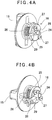
FIG.4A is a perspective view of an opened state of the lock module in which a lock plate is omitted, andFIG.4B is a perspective view of a locked state of the lock module in which the lock plate is omitted. - A description will be given below on an embodiment of the present invention by referring to the attached drawings.
-
FIG.1 is a perspective view of asurveying instrument 1 according to the present embodiment as viewed from the rear, andFIG.2A and FIG.2B are perspective views of abattery holder 4 as viewed from the front. - In
FIG.1 , areference numeral 2 denotes a surveying instrument main body, areference numeral 3 denotes a power supply unit, areference numeral 4 denotes the battery holder, and areference numeral 5 denotes a battery. - The
surveying instrument 1 mainly has the surveying instrumentmain body 2 and thepower supply unit 3. - The surveying instrument
main body 2 has a powersupply unit storage 7 which is opened to the rear. Thepower supply unit 3 is inserted into the powersupply unit storage 7 from a horizontal direction. - An abutting
surface 8 receding inward from a rear end surface of the surveying instrumentmain body 2 is formed around an opening of the powersupply unit storage 7. -
Lock pins 11 are protruded at two positions (left-and-right two positions in the drawing) adjacent to the opening on aflange surface 10 receding inward from theabutting surface 8. - The
power supply unit 3 is made up by thebattery holder 4 and thebattery 5, and thebattery 5 is mounted on thebattery holder 4 from above. - The
battery holder 4 consists of aflange part 13 and abattery case 14 which extends frontward. A shallow bottom concave portion is formed to thebattery case 14, and thebattery 5 is fitted in the concave portion from above. Electric contacts (not shown) are formed on a front end surface (in the drawing, an end surface on the surveying instrumentmain body 2 side) of thebattery 5. - The
flange part 13 abuts on theabutting surface 8 in such a manner that a receding part of theabutting surface 8 is filled. Further, theflange part 13 has alid 12 which closes the opening of the powersupply unit storage 7, and a lock module 16 (to be described later) is provided on theflange part 13. Thelock module 16 has alock knob 15, and thelock knob 15 is rotatable in theflange part 13 and is restrained from moving in an axial direction. Thelid 12 is provided with aseal 9, and theseal 9 can abut on a rim of the opening. It is to be noted that theseal 9 may be provided on theabutting surface 8 side. - By inserting the
power supply unit 3 into the powersupply unit storage 7, thelid 12 closes the opening, and theseal 9 abuts on the rim of the opening. In a state where thepower supply unit 3 is completely inserted , the electric contacts of thebattery 5 are joined with electric contacts on the surveying instrumentmain body 2 side. In a state where thepower supply unit 3 is inserted, when thelock knob 15 is rotated, thelock module 16 engages with thelock pins 11. Thereby, thepower supply unit 3 is fastened to the surveying instrumentmain body 2, theseal 9 closely adheres to the rim of the opening, and the opening is sealed liquid-tight. - A description will be given on the
lock module 16 by referring toFIG.2A, FIG.2B ,FIG.3 ,FIG.4A, and FIG.4B . -
FIG.2A and FIG.2B are perspective views of thebattery holder 4 as viewed from the front, whereFIG.2A shows an opened state andFIG.2B shows a locked state. InFIG.2A and FIG.2B , the right side is determined to be the front, and the left side is determined to be the rear. It is to be noted that thebattery 5 is omitted in the drawings. - Further, in
FIG.2A and FIG.2B ,reference numerals 11 denote lock pins, and as shown inFIG.1 , thelock pins 11 are protruded on theabutting surface 8 of the surveying instrumentmain body 2. - The
lock module 16 has alock plate 21 at a front surface position. Thelock plate 21 is accommodated in a space between theabutting surface 8 and theflange surface 10, and thelock plate 21 is rotatable in the space.Engagement holes 22 in which thelock pins 11 can be fitted are formed at both end portions of thelock plate 21. - After the
lock pins 11 are fitted in thelock plate 21, when thelock plate 21 is rotated at a predetermined angle, thelock plate 21 engages with thelock pins 11. Thereby, displacement in the axial direction between thelock plate 21 and thelock pins 11 is restrained, and the rotation is restricted by thelock pins 11. - Each of the
engagement holes 22 has a keyhole shape in which acircular hole 22a is continuous with along hole 22b. A diameter of thecircular hole 22a is larger than a diameter of thelong hole 22b. - Each of the
lock pins 11 has a stepped shape and is formed of ahead portion 11a, ashaft portion 11b, and ascrew portion 11c. A diameter of thehead portion 11a is smaller than the diameter of thecircular hole 22a and larger than the diameter of thelong hole 22b. Further, a diameter of theshaft portion 11b is smaller than the diameter of thelong hole 22b. Further, an axial length of theshaft portion 11b is slightly longer than a thickness of thelock plate 21. Thescrew portion 11c is available for fixing thelock pin 11 to theflange surface 10. - In the opened state as shown in
FIG.2A and also in a state where thebattery holder 4 is inserted into the powersupply unit storage 7, the axis of eachlock pin 11 coincides with the center of eachcircular hole 22a. Further, in a state where thebattery holder 4 is completely inserted into the powersupply unit storage 7, eachhead portion 11a passes through eachcircular hole 22a, and eachshaft portion 11b is loosely fitted in eachcircular hole 22a. - When the
lock knob 15 is turned in this state, thelock plate 21 rotates, and theshaft portions 11b are fitted in thelong holes 22b respectively. In a state where theshaft portions 11b are fitted in thelong holes 22b, since the diameter of eachhead portion 11a is larger than the diameter of eachlong hole 22b, the movement of thelock plate 21 in a front-and-rear direction is restrained by thelock pins 11. That is, thebattery holder 4 is fastened with respect to the surveying instrumentmain body 2 via thelock plate 21 and thelock pins 11. - A description will be further given on the
lock module 16 by referring toFIG.3 ,FIG.4A, and FIG.4B . It is to be noted that, inFIG.3 , to facilitate the understanding, only half of thelock plate 21 is shown. - A
discoid cam plate 25 is rotatably and slidably fitted on arotation shaft 24 of thelock knob 15. Thelock plate 21 is fixed to thecam plate 25 bybolts 27. Acompression spring 26 as an energizing means is provided in a compressed state on a rear surface side (a rear side) of thecam plate 25, and thecompression spring 26 biases thecam plate 25 toward a tip side (the right side inFIG.4A and FIG.4B ) of therotation shaft 24. That is, thecompression spring 26 biases thecam plate 25 in such a manner that thecam plate 25 is pressed against the lock pins 11. It is to be noted that the energizing means may be a coned disc spring, an elastic rubber, a waved washer, or the like. - A V-
groove 28 is formed on thecam plate 25. A center line of the V-groove 28 runs through the axis of therotation shaft 24 and is also orthogonal to the axis. - The
rotation shaft 24 passes through thecam plate 25, and acam pin 29 which is orthogonal to the axis of therotation shaft 24 is provided at a protruding tip portion of therotation shaft 24. It is to be noted that an axial length of thecam pin 29 is sufficiently shorter than a length (a diameter) of thelock knob 15. - An
escape hole 31 is formed at a central portion of thelock plate 21 in such a manner that an interference with therotation shaft 24 and thecam pin 29 is avoided. Theescape hole 31 has a shape which allows a relative rotation at a predetermined angle among thelock plate 21, therotation shaft 24, and thecam pin 29. For example, theescape hole 31 has a shape in which a fan shape is point-symmetrically arranged with respect to the center of therotation shaft 24, and a center angle of the fan shape has the predetermined angle of the relative rotation. -
FIG.4A shows an unlocked state of thelock module 16, and thecam pin 29 is fitted in the V-groove 28 by an energizing force of thecompression spring 26. Therefore, in a state where the rotation of thecam plate 25 is not restrained, thecam plate 25 and therotation shaft 24, that is, thelock knob 15, integrally rotate. - Next, when the rotation of the
cam plate 25 is restrained and further therotation shaft 24 is rotated in a restrained state, therotation shaft 24 is relatively rotated with respect to thecam plate 25. Thereby, thecam pin 29 gets over a slant surface of the V-groove 28 and runs up onto a flat surface of the cam plate 25 (FIG.4B ). - When the
cam pin 29 gets out of the V-groove 28 and runs up onto the flat surface of thecam plate 25, thecam plate 25 is displaced to thelock knob 15 side against the energizing force of thecompression spring 26. Actually, thecam plate 25 is fixed to thelock plate 21, thelock plate 21 is restrained by the lock pins 11, and hence thecam plate 25, that is, thelock knob 15 is displaced to the surveying instrumentmain body 2 side. Since the displacement of thelock knob 15 is a displacement of theflange part 13, theseal 9 is compressed, and the sealing is performed. - The cam plate 25fitted on the
rotation shaft 24 so that it can rotate and be axially displaced, the V-groove 28 formed on thecam plate 25, thecam pin 29 capable of fitting in the V-groove 28, thecompression spring 26, and the like make up a cam mechanism. The cam mechanism enables thecam pin 29 to get out of the V-groove 28 by restraining the rotation of thecam plate 25 and enables thecam plate 25 to move in the axial direction of therotation shaft 24. - It is to be noted that, when the
cam pin 29 gets out of the V-groove 28 and when theseal 9 is compressed, become loads the forces applied at the time of rotating thelock knob 15 become loads. However, the axial length of thecam pin 29 is short, a rotational resistance is limited to the vicinity of the rotation center, and hence a load torque to be produced is small. - A description will be given on a flow of mounting the
battery 5 to the surveying instrumentmain body 2 by referring toFIG.1 . - First, the
battery 5 is loaded onto thebattery case 14 from above in such a manner that thepower supply unit 3 is provided. Thepower supply unit 3 is inserted into the powersupply unit storage 7 from the horizontal direction. - The lock pins 11 are fitted in and pass through the
circular holes 22a. When thelock knob 15 is rotated, thecam plate 25 and thelock plate 21 rotate integrally with thelock knob 15, thelong holes 22b are fitted in theshaft portions 11b, and then theshaft portions 11b abut against end edges of thelong holes 22b respectively, and the rotation of thelock plate 21 is restrained. At the same time, the rotation of thecam plate 25 is also restrained. - When the
lock knob 15 is further rotated in the same direction, since therotation shaft 24 relatively rotates with respect to thecam plate 25, thecam pin 29 gets out of the V-groove 28 and runs up onto the flat surface of thecam plate 25. - The
lock knob 15 is displaced toward thelock plate 21, that is, theflange part 13 is displaced toward theabutting surface 8. Thereby, thelid 12 closes the opening, theseal 9 is compressed between thelid 12 and theabutting surface 8, and the sealing is performed between thelid 12 and theabutting surface 8. - Therefore, the rotation of the
lock knob 15 in one direction completes the locking and the sealing of thepower supply unit 3 with respect to the surveying instrumentmain body 2. It is to be noted that, in case of removing thepower supply unit 3, by rotating thelock knob 15 in a reverse direction, it is possible to easily remove thepower supply unit 3. - In the present embodiment, the
battery 5 can be easily mounted to thebattery holder 4 with no obstruction, and the rotation of thelock knob 15 in one direction suffices to mount thebattery holder 4 to the surveying instrumentmain body 2. As a result, it is possible to easily replace thebattery 5 of the surveyinginstrument 1.
Claims (3)
- A power supply unit mounting structure for mounting a power supply unit (3) which is inserted into a power supply unit storage (7) of a surveying instrument main body (2) comprising: two stepped lock pins (11) protruded adjacent to an opening of said power supply unit storage and a seal (9) provided in such a manner that said seal surrounds said opening, wherein said power supply unit comprises a flange part (13) and a lock module (16) provided on said flange part, wherein said lock module comprises a lock knob (15) which is rotatable and of which axis displacement is restrained, a lock plate (21) provided at a tip of a rotation shaft (24) of said lock knob, and a cam mechanism (25, 26, 28, 29) configured to displace said lock plate in an axial direction by restraining a rotation of said lock plate, wherein, at both end portions, said lock plate includes engagement holes (22) which are engageable with said lock pins, and wherein said lock pins are inserted into said engagement holes by inserting said power supply unit into said power supply unit storage, and by rotating said lock knob, said lock plate is rotated and said lock pins engage with said engagement holes, the rotation of said lock plate is restrained by said engagement holes, and by rotating said lock knob after restraining the rotation of said lock plate, said flange part is displaced to said opening side, said seal is pressed, and said opening is sealed.
- The power supply unit mounting structure according to claim 1, wherein said cam mechanism comprises a cam plate (25) which is rotatably and slidably provided to said rotation shaft (24), a V-groove (28) formed on said cam plate, a cam pin (29) provided at a tip portion of said rotation shaft in such a manner that said cam pin is orthogonal to a rotation axis and which is fittable and removable with respect to said V-groove, and an energizing means (26) which energizes said cam plate in such a manner that said cam plate is pressed against said cam pin, and wherein said lock plate (21) is fixed to said cam plate.
- A surveying instrument comprising a surveying instrument main body (2) which has a power supply unit storage (7), a power supply unit (3) which is inserted into said power supply unit storage, and said power supply unit mounting structure according to claim 1.
Applications Claiming Priority (1)
| Application Number | Priority Date | Filing Date | Title |
|---|---|---|---|
| JP2019059777A JP7224991B2 (en) | 2019-03-27 | 2019-03-27 | Power supply unit mounting structure and surveying equipment |
Publications (1)
| Publication Number | Publication Date |
|---|---|
| EP3716354A1 true EP3716354A1 (en) | 2020-09-30 |
Family
ID=70008326
Family Applications (1)
| Application Number | Title | Priority Date | Filing Date |
|---|---|---|---|
| EP20165584.2A Withdrawn EP3716354A1 (en) | 2019-03-27 | 2020-03-25 | Power supply unit mounting structure and surveying instrument |
Country Status (3)
| Country | Link |
|---|---|
| US (1) | US11274923B2 (en) |
| EP (1) | EP3716354A1 (en) |
| JP (1) | JP7224991B2 (en) |
Cited By (2)
| Publication number | Priority date | Publication date | Assignee | Title |
|---|---|---|---|---|
| CN114824629A (en) * | 2022-05-18 | 2022-07-29 | 武汉长江光电有限公司 | Quick locking device of battery clamp |
| GB2621008A (en) * | 2022-05-23 | 2024-01-31 | Ocado Innovation Ltd | Power source retention system |
Families Citing this family (1)
| Publication number | Priority date | Publication date | Assignee | Title |
|---|---|---|---|---|
| JP7267061B2 (en) | 2019-03-27 | 2023-05-01 | 株式会社トプコン | battery holder |
Citations (2)
| Publication number | Priority date | Publication date | Assignee | Title |
|---|---|---|---|---|
| EP2082848A1 (en) * | 2008-01-24 | 2009-07-29 | Robert Bosch Gmbh | An electrical device having a battery pack with an easy attachment and release mechanism |
| US20190025883A1 (en) * | 2016-01-16 | 2019-01-24 | Jsc Yukon Advanced Optics Worldwide | Securely mounting electronic device battery pack |
Family Cites Families (14)
| Publication number | Priority date | Publication date | Assignee | Title |
|---|---|---|---|---|
| JPS622452A (en) | 1985-06-27 | 1987-01-08 | Matsushita Electric Ind Co Ltd | battery holder |
| US5280273A (en) | 1992-12-21 | 1994-01-18 | Goldstein Mark K | Toxic gas detector system having convenient battery and sensor replacement |
| US5626979A (en) | 1994-04-08 | 1997-05-06 | Sony Corporation | Battery device and electronic equipment employing the battery device as power source |
| JP3428182B2 (en) * | 1994-11-18 | 2003-07-22 | 株式会社ニコン | Surveying instrument |
| JP3681820B2 (en) * | 1996-06-18 | 2005-08-10 | 株式会社ニコン | Surveyor with battery pack |
| JP3691166B2 (en) * | 1996-08-09 | 2005-08-31 | 株式会社ソキア | Surveyor battery pack attachment / detachment mechanism |
| JP2000249550A (en) | 1999-03-01 | 2000-09-14 | Asahi Precision Co Ltd | Power unit for electronic surveying instrument |
| JP2003047158A (en) | 2001-07-31 | 2003-02-14 | Topcon Corp | Surveying equipment |
| US6530804B1 (en) | 2002-04-11 | 2003-03-11 | Hon Hai Precision Ind. Co., Ltd. | Battery holder |
| JP4752277B2 (en) | 2005-02-04 | 2011-08-17 | 双葉電子工業株式会社 | Battery lock structure in electronic equipment |
| JP5049634B2 (en) | 2007-04-03 | 2012-10-17 | ペンタックスリコーイメージング株式会社 | Battery holder locking mechanism |
| JP6004774B2 (en) | 2011-12-16 | 2016-10-12 | モテックス プロダクツ カンパニー リミテッド | Battery removal device for electric vehicles |
| JP6654649B2 (en) * | 2015-12-14 | 2020-02-26 | 株式会社ニコン・トリンブル | Defect detection device and program |
| JP7267061B2 (en) | 2019-03-27 | 2023-05-01 | 株式会社トプコン | battery holder |
-
2019
- 2019-03-27 JP JP2019059777A patent/JP7224991B2/en active Active
-
2020
- 2020-03-16 US US16/819,609 patent/US11274923B2/en active Active
- 2020-03-25 EP EP20165584.2A patent/EP3716354A1/en not_active Withdrawn
Patent Citations (3)
| Publication number | Priority date | Publication date | Assignee | Title |
|---|---|---|---|---|
| EP2082848A1 (en) * | 2008-01-24 | 2009-07-29 | Robert Bosch Gmbh | An electrical device having a battery pack with an easy attachment and release mechanism |
| EP2082848B1 (en) * | 2008-01-24 | 2013-04-10 | Robert Bosch Gmbh | An electrical device having a battery pack with an easy attachment and release mechanism |
| US20190025883A1 (en) * | 2016-01-16 | 2019-01-24 | Jsc Yukon Advanced Optics Worldwide | Securely mounting electronic device battery pack |
Cited By (4)
| Publication number | Priority date | Publication date | Assignee | Title |
|---|---|---|---|---|
| CN114824629A (en) * | 2022-05-18 | 2022-07-29 | 武汉长江光电有限公司 | Quick locking device of battery clamp |
| CN114824629B (en) * | 2022-05-18 | 2024-02-13 | 武汉长江光电有限公司 | Quick locking device of battery clamp |
| GB2621008A (en) * | 2022-05-23 | 2024-01-31 | Ocado Innovation Ltd | Power source retention system |
| GB2621008B (en) * | 2022-05-23 | 2025-01-08 | Ocado Innovation Ltd | Power source retention system |
Also Published As
| Publication number | Publication date |
|---|---|
| US20200309522A1 (en) | 2020-10-01 |
| JP2020159873A (en) | 2020-10-01 |
| US11274923B2 (en) | 2022-03-15 |
| JP7224991B2 (en) | 2023-02-20 |
Similar Documents
| Publication | Publication Date | Title |
|---|---|---|
| US11274923B2 (en) | Power supply unit mounting structure and surveying instrument | |
| US9350118B2 (en) | Charging port locking device | |
| CN103025555B (en) | The mounting structure of the embedding case of vehicle | |
| US20030066667A1 (en) | Tool head attachment mechanism | |
| US6401302B1 (en) | Motor vehicle opening leaf handle | |
| TW201821318A (en) | Rotation locking device, vehicle lock using the rotation locking device and control method for locking | |
| JP6811126B2 (en) | Actuator | |
| JP6096715B2 (en) | Cylinder lock device | |
| JP2000038033A (en) | Covering device, especially covering plate for exterior door handle of automobile door | |
| JP2022140335A (en) | Charging flap configuration for automobiles | |
| JPH01315237A (en) | Power actuator with electric/manual switching mechanism | |
| EP3716355B1 (en) | Battery holder | |
| CN114435120A (en) | Actuating assembly and oil filler hole or charging hole flip assembly | |
| US20060230623A1 (en) | Tool | |
| EP1916064B1 (en) | Power tool with spindle lock | |
| JP2010106438A (en) | Lid locking device for vehicle | |
| US7946942B2 (en) | Power pivot device | |
| CN210234708U (en) | locking mechanism | |
| CN219834259U (en) | Vehicle-mounted camera | |
| KR102152336B1 (en) | Spindle locking apparatus, electronic tool and actuator for vehicle using the same | |
| CN114652226A (en) | Bottom shell | |
| CN210258090U (en) | System for locking or unlocking a second member under a first member | |
| CN222114929U (en) | Torsion screwdriver | |
| CN211144084U (en) | Locking structure and bicycle | |
| CN220692235U (en) | Battery cover assembly and thermal imaging instrument |
Legal Events
| Date | Code | Title | Description |
|---|---|---|---|
| PUAI | Public reference made under article 153(3) epc to a published international application that has entered the european phase |
Free format text: ORIGINAL CODE: 0009012 |
|
| STAA | Information on the status of an ep patent application or granted ep patent |
Free format text: STATUS: THE APPLICATION HAS BEEN PUBLISHED |
|
| AK | Designated contracting states |
Kind code of ref document: A1 Designated state(s): AL AT BE BG CH CY CZ DE DK EE ES FI FR GB GR HR HU IE IS IT LI LT LU LV MC MK MT NL NO PL PT RO RS SE SI SK SM TR |
|
| AX | Request for extension of the european patent |
Extension state: BA ME |
|
| STAA | Information on the status of an ep patent application or granted ep patent |
Free format text: STATUS: REQUEST FOR EXAMINATION WAS MADE |
|
| 17P | Request for examination filed |
Effective date: 20201210 |
|
| RBV | Designated contracting states (corrected) |
Designated state(s): AL AT BE BG CH CY CZ DE DK EE ES FI FR GB GR HR HU IE IS IT LI LT LU LV MC MK MT NL NO PL PT RO RS SE SI SK SM TR |
|
| STAA | Information on the status of an ep patent application or granted ep patent |
Free format text: STATUS: EXAMINATION IS IN PROGRESS |
|
| 17Q | First examination report despatched |
Effective date: 20210128 |
|
| STAA | Information on the status of an ep patent application or granted ep patent |
Free format text: STATUS: THE APPLICATION IS DEEMED TO BE WITHDRAWN |
|
| 18D | Application deemed to be withdrawn |
Effective date: 20250301 |