EP3716351A1 - Secondary battery - Google Patents
Secondary battery Download PDFInfo
- Publication number
- EP3716351A1 EP3716351A1 EP19815125.0A EP19815125A EP3716351A1 EP 3716351 A1 EP3716351 A1 EP 3716351A1 EP 19815125 A EP19815125 A EP 19815125A EP 3716351 A1 EP3716351 A1 EP 3716351A1
- Authority
- EP
- European Patent Office
- Prior art keywords
- secondary battery
- insulation layer
- top cap
- battery
- safety vent
- Prior art date
- Legal status (The legal status is an assumption and is not a legal conclusion. Google has not performed a legal analysis and makes no representation as to the accuracy of the status listed.)
- Pending
Links
Images

Classifications
-
- H—ELECTRICITY
- H01—ELECTRIC ELEMENTS
- H01M—PROCESSES OR MEANS, e.g. BATTERIES, FOR THE DIRECT CONVERSION OF CHEMICAL ENERGY INTO ELECTRICAL ENERGY
- H01M50/00—Constructional details or processes of manufacture of the non-active parts of electrochemical cells other than fuel cells, e.g. hybrid cells
- H01M50/30—Arrangements for facilitating escape of gases
- H01M50/342—Non-re-sealable arrangements
- H01M50/3425—Non-re-sealable arrangements in the form of rupturable membranes or weakened parts, e.g. pierced with the aid of a sharp member
-
- H—ELECTRICITY
- H01—ELECTRIC ELEMENTS
- H01M—PROCESSES OR MEANS, e.g. BATTERIES, FOR THE DIRECT CONVERSION OF CHEMICAL ENERGY INTO ELECTRICAL ENERGY
- H01M50/00—Constructional details or processes of manufacture of the non-active parts of electrochemical cells other than fuel cells, e.g. hybrid cells
- H01M50/10—Primary casings; Jackets or wrappings
- H01M50/147—Lids or covers
- H01M50/166—Lids or covers characterised by the methods of assembling casings with lids
-
- H—ELECTRICITY
- H01—ELECTRIC ELEMENTS
- H01M—PROCESSES OR MEANS, e.g. BATTERIES, FOR THE DIRECT CONVERSION OF CHEMICAL ENERGY INTO ELECTRICAL ENERGY
- H01M50/00—Constructional details or processes of manufacture of the non-active parts of electrochemical cells other than fuel cells, e.g. hybrid cells
- H01M50/10—Primary casings; Jackets or wrappings
- H01M50/147—Lids or covers
- H01M50/155—Lids or covers characterised by the material
-
- H—ELECTRICITY
- H01—ELECTRIC ELEMENTS
- H01M—PROCESSES OR MEANS, e.g. BATTERIES, FOR THE DIRECT CONVERSION OF CHEMICAL ENERGY INTO ELECTRICAL ENERGY
- H01M10/00—Secondary cells; Manufacture thereof
- H01M10/05—Accumulators with non-aqueous electrolyte
- H01M10/052—Li-accumulators
-
- H—ELECTRICITY
- H01—ELECTRIC ELEMENTS
- H01M—PROCESSES OR MEANS, e.g. BATTERIES, FOR THE DIRECT CONVERSION OF CHEMICAL ENERGY INTO ELECTRICAL ENERGY
- H01M50/00—Constructional details or processes of manufacture of the non-active parts of electrochemical cells other than fuel cells, e.g. hybrid cells
- H01M50/10—Primary casings; Jackets or wrappings
- H01M50/102—Primary casings; Jackets or wrappings characterised by their shape or physical structure
- H01M50/107—Primary casings; Jackets or wrappings characterised by their shape or physical structure having curved cross-section, e.g. round or elliptic
-
- H—ELECTRICITY
- H01—ELECTRIC ELEMENTS
- H01M—PROCESSES OR MEANS, e.g. BATTERIES, FOR THE DIRECT CONVERSION OF CHEMICAL ENERGY INTO ELECTRICAL ENERGY
- H01M50/00—Constructional details or processes of manufacture of the non-active parts of electrochemical cells other than fuel cells, e.g. hybrid cells
- H01M50/10—Primary casings; Jackets or wrappings
- H01M50/116—Primary casings; Jackets or wrappings characterised by the material
-
- H—ELECTRICITY
- H01—ELECTRIC ELEMENTS
- H01M—PROCESSES OR MEANS, e.g. BATTERIES, FOR THE DIRECT CONVERSION OF CHEMICAL ENERGY INTO ELECTRICAL ENERGY
- H01M50/00—Constructional details or processes of manufacture of the non-active parts of electrochemical cells other than fuel cells, e.g. hybrid cells
- H01M50/10—Primary casings; Jackets or wrappings
- H01M50/147—Lids or covers
-
- H—ELECTRICITY
- H01—ELECTRIC ELEMENTS
- H01M—PROCESSES OR MEANS, e.g. BATTERIES, FOR THE DIRECT CONVERSION OF CHEMICAL ENERGY INTO ELECTRICAL ENERGY
- H01M50/00—Constructional details or processes of manufacture of the non-active parts of electrochemical cells other than fuel cells, e.g. hybrid cells
- H01M50/10—Primary casings; Jackets or wrappings
- H01M50/147—Lids or covers
- H01M50/148—Lids or covers characterised by their shape
- H01M50/152—Lids or covers characterised by their shape for cells having curved cross-section, e.g. round or elliptic
-
- H—ELECTRICITY
- H01—ELECTRIC ELEMENTS
- H01M—PROCESSES OR MEANS, e.g. BATTERIES, FOR THE DIRECT CONVERSION OF CHEMICAL ENERGY INTO ELECTRICAL ENERGY
- H01M50/00—Constructional details or processes of manufacture of the non-active parts of electrochemical cells other than fuel cells, e.g. hybrid cells
- H01M50/10—Primary casings; Jackets or wrappings
- H01M50/147—Lids or covers
- H01M50/155—Lids or covers characterised by the material
- H01M50/162—Composite material consisting of a mixture of organic and inorganic materials
-
- H—ELECTRICITY
- H01—ELECTRIC ELEMENTS
- H01M—PROCESSES OR MEANS, e.g. BATTERIES, FOR THE DIRECT CONVERSION OF CHEMICAL ENERGY INTO ELECTRICAL ENERGY
- H01M50/00—Constructional details or processes of manufacture of the non-active parts of electrochemical cells other than fuel cells, e.g. hybrid cells
- H01M50/10—Primary casings; Jackets or wrappings
- H01M50/147—Lids or covers
- H01M50/155—Lids or covers characterised by the material
- H01M50/164—Lids or covers characterised by the material having a layered structure
-
- H—ELECTRICITY
- H01—ELECTRIC ELEMENTS
- H01M—PROCESSES OR MEANS, e.g. BATTERIES, FOR THE DIRECT CONVERSION OF CHEMICAL ENERGY INTO ELECTRICAL ENERGY
- H01M50/00—Constructional details or processes of manufacture of the non-active parts of electrochemical cells other than fuel cells, e.g. hybrid cells
- H01M50/10—Primary casings; Jackets or wrappings
- H01M50/147—Lids or covers
- H01M50/166—Lids or covers characterised by the methods of assembling casings with lids
- H01M50/167—Lids or covers characterised by the methods of assembling casings with lids by crimping
-
- H—ELECTRICITY
- H01—ELECTRIC ELEMENTS
- H01M—PROCESSES OR MEANS, e.g. BATTERIES, FOR THE DIRECT CONVERSION OF CHEMICAL ENERGY INTO ELECTRICAL ENERGY
- H01M50/00—Constructional details or processes of manufacture of the non-active parts of electrochemical cells other than fuel cells, e.g. hybrid cells
- H01M50/10—Primary casings; Jackets or wrappings
- H01M50/172—Arrangements of electric connectors penetrating the casing
-
- H—ELECTRICITY
- H01—ELECTRIC ELEMENTS
- H01M—PROCESSES OR MEANS, e.g. BATTERIES, FOR THE DIRECT CONVERSION OF CHEMICAL ENERGY INTO ELECTRICAL ENERGY
- H01M50/00—Constructional details or processes of manufacture of the non-active parts of electrochemical cells other than fuel cells, e.g. hybrid cells
- H01M50/10—Primary casings; Jackets or wrappings
- H01M50/183—Sealing members
-
- H—ELECTRICITY
- H01—ELECTRIC ELEMENTS
- H01M—PROCESSES OR MEANS, e.g. BATTERIES, FOR THE DIRECT CONVERSION OF CHEMICAL ENERGY INTO ELECTRICAL ENERGY
- H01M50/00—Constructional details or processes of manufacture of the non-active parts of electrochemical cells other than fuel cells, e.g. hybrid cells
- H01M50/10—Primary casings; Jackets or wrappings
- H01M50/183—Sealing members
- H01M50/19—Sealing members characterised by the material
- H01M50/191—Inorganic material
-
- H—ELECTRICITY
- H01—ELECTRIC ELEMENTS
- H01M—PROCESSES OR MEANS, e.g. BATTERIES, FOR THE DIRECT CONVERSION OF CHEMICAL ENERGY INTO ELECTRICAL ENERGY
- H01M50/00—Constructional details or processes of manufacture of the non-active parts of electrochemical cells other than fuel cells, e.g. hybrid cells
- H01M50/40—Separators; Membranes; Diaphragms; Spacing elements inside cells
- H01M50/471—Spacing elements inside cells other than separators, membranes or diaphragms; Manufacturing processes thereof
- H01M50/474—Spacing elements inside cells other than separators, membranes or diaphragms; Manufacturing processes thereof characterised by their position inside the cells
-
- H—ELECTRICITY
- H01—ELECTRIC ELEMENTS
- H01M—PROCESSES OR MEANS, e.g. BATTERIES, FOR THE DIRECT CONVERSION OF CHEMICAL ENERGY INTO ELECTRICAL ENERGY
- H01M50/00—Constructional details or processes of manufacture of the non-active parts of electrochemical cells other than fuel cells, e.g. hybrid cells
- H01M50/50—Current conducting connections for cells or batteries
- H01M50/572—Means for preventing undesired use or discharge
- H01M50/574—Devices or arrangements for the interruption of current
- H01M50/578—Devices or arrangements for the interruption of current in response to pressure
-
- H—ELECTRICITY
- H01—ELECTRIC ELEMENTS
- H01M—PROCESSES OR MEANS, e.g. BATTERIES, FOR THE DIRECT CONVERSION OF CHEMICAL ENERGY INTO ELECTRICAL ENERGY
- H01M50/00—Constructional details or processes of manufacture of the non-active parts of electrochemical cells other than fuel cells, e.g. hybrid cells
- H01M50/50—Current conducting connections for cells or batteries
- H01M50/572—Means for preventing undesired use or discharge
- H01M50/574—Devices or arrangements for the interruption of current
- H01M50/581—Devices or arrangements for the interruption of current in response to temperature
-
- H—ELECTRICITY
- H01—ELECTRIC ELEMENTS
- H01M—PROCESSES OR MEANS, e.g. BATTERIES, FOR THE DIRECT CONVERSION OF CHEMICAL ENERGY INTO ELECTRICAL ENERGY
- H01M50/00—Constructional details or processes of manufacture of the non-active parts of electrochemical cells other than fuel cells, e.g. hybrid cells
- H01M50/50—Current conducting connections for cells or batteries
- H01M50/572—Means for preventing undesired use or discharge
- H01M50/574—Devices or arrangements for the interruption of current
- H01M50/583—Devices or arrangements for the interruption of current in response to current, e.g. fuses
-
- H—ELECTRICITY
- H01—ELECTRIC ELEMENTS
- H01M—PROCESSES OR MEANS, e.g. BATTERIES, FOR THE DIRECT CONVERSION OF CHEMICAL ENERGY INTO ELECTRICAL ENERGY
- H01M50/00—Constructional details or processes of manufacture of the non-active parts of electrochemical cells other than fuel cells, e.g. hybrid cells
- H01M50/50—Current conducting connections for cells or batteries
- H01M50/531—Electrode connections inside a battery casing
-
- Y—GENERAL TAGGING OF NEW TECHNOLOGICAL DEVELOPMENTS; GENERAL TAGGING OF CROSS-SECTIONAL TECHNOLOGIES SPANNING OVER SEVERAL SECTIONS OF THE IPC; TECHNICAL SUBJECTS COVERED BY FORMER USPC CROSS-REFERENCE ART COLLECTIONS [XRACs] AND DIGESTS
- Y02—TECHNOLOGIES OR APPLICATIONS FOR MITIGATION OR ADAPTATION AGAINST CLIMATE CHANGE
- Y02E—REDUCTION OF GREENHOUSE GAS [GHG] EMISSIONS, RELATED TO ENERGY GENERATION, TRANSMISSION OR DISTRIBUTION
- Y02E60/00—Enabling technologies; Technologies with a potential or indirect contribution to GHG emissions mitigation
- Y02E60/10—Energy storage using batteries
-
- Y—GENERAL TAGGING OF NEW TECHNOLOGICAL DEVELOPMENTS; GENERAL TAGGING OF CROSS-SECTIONAL TECHNOLOGIES SPANNING OVER SEVERAL SECTIONS OF THE IPC; TECHNICAL SUBJECTS COVERED BY FORMER USPC CROSS-REFERENCE ART COLLECTIONS [XRACs] AND DIGESTS
- Y02—TECHNOLOGIES OR APPLICATIONS FOR MITIGATION OR ADAPTATION AGAINST CLIMATE CHANGE
- Y02P—CLIMATE CHANGE MITIGATION TECHNOLOGIES IN THE PRODUCTION OR PROCESSING OF GOODS
- Y02P70/00—Climate change mitigation technologies in the production process for final industrial or consumer products
- Y02P70/50—Manufacturing or production processes characterised by the final manufactured product
Definitions
- the present invention relates to a secondary battery, and more particularly, to a secondary battery having a structure capable of solving safety problems that may occur due to external short circuit.
- a secondary battery may be classified into a cylindrical or prismatic secondary battery having a structure in which an electrode assembly including an electrode and a separator is accommodated in a cylindrical or prismatic metal can and a pouch-type secondary battery having a structure in which an electrode assembly is accommodated in a pouch-type case containing aluminum according to structural characteristics or manufacturing characteristics.
- the cylindrical secondary battery has advantages in that it has relatively large capacity and is structurally stable.
- the secondary battery including a cylindrical secondary battery
- the secondary battery may be exposed to various types of risks during the use. In this case, problems such as ignition or explosion of the secondary battery may occur.
- the secondary battery is generally provided with various members for improving safety of the secondary battery.
- the members for improving the safety of the secondary battery may include, for example, a crimping gasket provided between a crimping part formed in an upper portion of a battery can constituting a main body of the secondary battery and a top cap or a safety vent to seal an inner space of the secondary battery from the outside and a CID gasket provided between the safety vent and a current interrupt device (CID) filter.
- a crimping gasket provided between a crimping part formed in an upper portion of a battery can constituting a main body of the secondary battery and a top cap or a safety vent to seal an inner space of the secondary battery from the outside
- a CID gasket provided between the safety vent and a current interrupt device (CID) filter.
- CID current interrupt device
- An object to be solved by the present invention is to quickly cut off current by breaking an electrode tab as quickly as possible when an external electrical conductive object is electrically connected directly to a positive electrode and a negative electrode of a cylindrical secondary battery.
- a secondary battery including: a battery can accommodating an electrode assembly and having a structure of which an upper side is opened; a top cap provided on an upper portion of the battery can; a safety vent provided below the top cap; a current interrupt device (CID) filter provided below the safety vent; a first gasket provided on an inner surface of the upper portion of the battery can and closely attached to a side portion of the safety vent to insulate the safety vent from the upper portion of the battery can; and a second gasket provided between the safety vent and the CID filter and closely attached to an upper portion of the CID filter to surround an outer end of the CID filter, the second gasket being closely attached to a lower portion of the safety vent, wherein an insulation layer is formed on an area on which the top cap and the first gasket are closely attached to each other.
- CID current interrupt device
- the insulation layer may include a ceramic material and a binder.
- the ceramic material may include aluminum oxide or silicon oxide.
- the binder may be contained at a content of 20 wt% to 90 wt% on the basis of a total weight of the insulation layer.
- a ratio of a thickness of the insulation layer to a thickness of the top cap may range of 0.015 to 0.15.
- a crimping part having a structure that is entirely or partially bent in an S-shape may be formed on the upper portion of the battery can, and the first gasket may be closely attached to an inner surface of the crimping part.
- the insulation layer may be formed on an area, which is disposed between an upper end of the crimping part and the top cap, of an inner area of the first gasket as a top surface of the top cap.
- the insulation layer may have a thickness of 0.015 mm to 0.045 mm.
- the top cap may have a thickness of 0.3 mm to 1.0 mm.
- the electrode tab of the secondary battery may be broken as quickly as possible to quickly cut off the current.
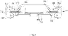
- FIG. 1 is a cross-sectional view illustrating an upper structure of a secondary battery according to a first example of the present invention
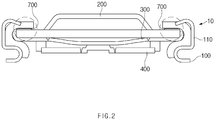
- FIG. 2 is a cross-sectional view illustrating an upper structure of a secondary battery according to a second example of the present invention.
- a secondary battery 10 may include a battery can 100 that accommodates an electrode assembly (not shown).
- the battery can 100 may have a structure of which an upper side is opened.
- the battery can 100 may have a cylindrical shape. That is, the secondary battery according to the present invention may be a cylindrical secondary battery.
- a crimping part 110 having a structure that is bent in an S-shape may be formed in an upper portion of the battery can 100.
- the expression 'the crimping part 110 has a structure bent in the S-shape' means that the crimping part 110 has at least one region protruding to the outside of the battery can and at least one region protruding to the inside of the battery can.
- an upper portion of the crimping part 110 may protrude to the outside of the battery can 100, and a lower portion of the crimping part 110 may protrude to the inside of the battery can 100.
- a top cap 200 may be disposed in the upper portion of the battery can 100.
- the top cap 200 may be a constituent for sealing the opened upper portion of the battery can 100.
- a safety vent 300 may be provided below the top cap 200.
- the safety vent 300 may be a constituent for exhausting a gas within the secondary battery when an internal pressure of the secondary battery exceeds a predetermined range.
- a notch 310 having a thickness less than that of each of other portions thereof may be formed in the safety vent 300.
- the notch formed in the safety vent 300 will be called a 'first notch 310'.
- the safety vent 300 may be closely attached to a lower portion of the top cap 200.
- an end of the safety vent 300 may be bent upward and then bent again to the inside of the battery can so that the end of the safety vent 300 surrounds a peripheral portion of the top cap 200.
- the safety vent 300 may have a structure in which an end of the safety vent 300 is bent upward only once to surround a side surface of the top cap 200.
- a current interrupt device (CID) filter 400 may be provided below the safety vent 300.
- a portion of an area of the safety vent 300 and a portion of an area of the CID filter 400 may be closely attached to each other or adhere to each other.
- a central portion of the safety vent 300 and a central portion of the CID filter 400 may be closely attached to each other or adhere to each other.
- the safety vent 300 and the CID filter 400 may be spaced apart from each other except for the areas on which the safety vent 300 and the CID filter are closely attached to each other or adhere to each other.
- the CID filter 400 may be a constituent configured to cut off the current of the secondary battery in emergency.
- a notch 410 having a thickness less than that of each of other portions thereof may be formed in the CID filter 400.
- the notch formed in the CID filter 400 will be called a 'second notch 410'.
- the top cap and the safety vent may be provided in the upper portion of the battery can. Nevertheless, sealability of the inner space of the battery can may be deteriorated as ever. When the sealability is deteriorated, an electrolyte within the secondary battery may leak to the outside, and external foreign substances may be introduced into the secondary battery.
- a gasket 500 may be additionally provided in the upper portion of the battery can 100.
- the gasket 500 may be disposed on an inner surface of the upper portion of the battery can 100.
- the gasket 500 may be closely attached to the inner surface of the crimping part 110.
- the gasket 500 may be disposed between the crimping part 110 and the safety vent and be closely attached to an outer portion of the safety vent.
- the gasket 500 disposed in the upper portion of the battery can 100 will be called a 'first gasket'.
- the first gasket 500 may be provided to more improve the sealability of the inner space of the battery can.
- the portion of the area of the safety vent 300 and the portion of the area of the CID filter 400 may be closely attached to each other or adhere to each other, and the safety vent 300 and the CID filter 400 may be spaced apart from each other on other areas thereof.
- the gasket 600 may be provided between the safety vent 300 and the CID filter 400 so that the areas on which the safety vent 300 and the CID filter 400 are spaced apart from each other are maintained to be spaced apart from each other.
- the gasket 600 provided on the safety vent 300 and the CID filter 400 will be called a 'second gasket'.
- the second gasket 600 may be provided to maintain the spaced state of the areas on which the safety vent 300 and the CID filter 400 are spaced apart from each other.
- an insulation layer 700 may be formed on an area on which the top cap 200 and the first gasket 500 are closely attached to each other in the secondary battery according to the present invention. More preferably, the insulation layer 700 may adhere to an area (see a dotted line in FIG. 2 ), on which the top cap 200 and the first gasket 500 are closely attached to each other, of a top surface of the top cap 200. For example, the insulation layer 700 may be formed on the top surface of the top cap 200 in a spray injection manner.
- the insulation layer 700 may be formed in a coating manner in which a material forming the insulation layer is applied and pressed to the top surface of the top cap 200 or in a manner in which the material forming the insulation layer is injected by nozzle to the top surface of the top cap 200 through a nozzle.
- the insulation layer 700 may contain a ceramic material and a binder.
- the ceramic material may include aluminum oxide or silicon oxide.
- the electrode tab of the secondary battery be cut off as quickly as possible when the external electrical conductive object is electrically connected directly to the positive electrode and the negative electrode of the cylindrical secondary battery.
- the positive electrode and the negative electrode of the secondary battery are electrically directly connected to each other by the external electrical conductive object, there is a problem in that a considerable time is required to cut off the current by breaking the electrode tab.
- the insulation layer according to the present invention may be a constituent for solving the problem in which it takes a considerable time to break the electrode tab. That is, as a result of conducting experiments by the inventor of the present invention, in the case in which a separate insulation layer containing the ceramic material and the binder is formed on the top surface of the top cap under certain conditions, when the external electrical conductive object is electrically connected directly to the positive electrode and the negative electrode of the cylindrical secondary battery, a time taken to cut off the current by breaking the electrode tab may be remarkably reduced.
- the insulation layer 700 of the present invention includes the ceramic material as well as the binder, the insulation layer having a larger thickness than that when forming an insulating layer using the ceramic material in another manner may be formed.
- evaporation may be used as the method of applying the ceramic material to the top cap.
- the thickness of the insulation layer may be limited. That is, when the ceramic material is applied to the top cap in the evaporation manner to form the insulation layer, if the thickness of the insulation layer increases, the insulation layer may be delaminated due to the deterioration of the adhesion force between the ceramic materials. Thus, the thickness of the insulation layer may be limited.
- the thickness of the insulation layer decreases, heat generated in the secondary battery, particularly, in the secondary battery in which the electrode tab is electrically connected to the CID filter may be easily released. As described above, when the heat generated in the upper portion of the secondary battery is released, since a temperature of the electrode tab does not rapidly increase, it may take a considerable time to cut off the current by breaking the electrode tab.
- the insulation layer according to the present invention includes not only the ceramic material but also the binder, bonding force between the ceramic materials may be improved by the binder.
- the insulation layer having the thick thickness is formed on the top cap, the shape of the insulation layer may be maintained to prevent the heat generated in the upper portion of the secondary battery from being released to the outside. Therefore, according to the present invention, when the external electrical conductive object is electrically connected directly to the positive electrode and the negative electrode of the cylindrical secondary battery, the electrode tab may be quickly broken.
- the external electrical conductive object When the external electrical conductive object is electrically connected directly to the positive electrode and the negative electrode of the cylindrical secondary battery, if the electrode tab is not quickly broken, the entire temperature of the secondary battery may sharply increase. This may cause explosion or fire of the secondary battery.
- the current of the secondary battery may be cut off to prevent the secondary battery from sharply increasing in temperature. That is, according to the present invention, a local temperature rise may be induced in a space in which the electrode tab is formed to quickly break the electrode tab and prevent the secondary battery from sharply increasing in temperature.
- the binder of the insulation layer according to the present invention may include an organic binder.
- the insulation layer may be formed through the coating in the spray injection manner.
- the binder includes the organic binder, since the material forming the insulation layer is maintained in a liquid phase in the coating step using the spray injection manner, the coating using the spray injection manner may be smoothly performed.
- the binder may be contained at a content of 20 wt% to 90 wt%, preferably, 30 wt% to 70 wt%, more preferably, 40 wt% to 50 wt% on the basis of the total weight of the insulation layer.
- the content of the binder is less than 20 wt% on the basis of the total weight of the insulation layer, the bonding between the ceramic materials may not be smoothly performed.
- the content of the binder exceeds 90 wt% on the basis of the total weight of the insulation layer, since an amount of ceramic material is excessively small, the heat generated in the upper portion of the secondary battery may be released to the outside. Thus, the electrode tab may not be quickly broken.
- the insulation layer 700 may be formed between an end of the upper portion of the crimping part 110 (i.e., a portion of the crimping part, which is bent from the upper portion of the crimping part to the inside of the battery can) and the top cap 200 in an internal area I (see FIG. 3 ) of the first gasket 500.
- an effect of preventing the battery can 100 and the safety vent 300 from directly contacting each other may be achieved.
- a ratio of the thickness of the insulation layer 700 to a thickness of the top cap 200 may range of 0.015 to 0.15.
- the ratio of the thickness of the insulation layer 700 to a thickness of the top cap 200 is less than 0.015, since the thickness of the insulation layer is excessively small, the heat generated in the upper portion of the secondary battery may be smoothly released to the outside.
- the electrode tab may not be quickly broken.
- the ratio of the thickness of the insulation layer 700 to the thickness of the top cap 200 exceeds 0.15, since the thickness of the insulation layer is excessively large, assemblability of the secondary battery, particularly, the top cap may be deteriorated, and the secondary battery may be deformed. More preferably, the ratio of the thickness of the insulation layer 700 to the thickness of the top cap 200 may range of 0.021 to 0.064.
- the insulation layer 700 may have a thickness of 0.015 mm to 0.045 mm.
- the top cap 200 may have a thickness of 0.3 mm to 1.0 mm.
- Silicon dioxide (SiO2), an organic binder, and an inorganic binder were added to a solvent isopropyl alcohol and dipropyleneglycol monomethyl ether to manufacture a composition for forming an insulation layer.
- the silicon dioxide was contained at a content of 20 wt%
- the organic binder was contained at a content of 10 wt%
- the inorganic binder was contained at a content of 20 wt% on the basis of a total weight of the composition for forming the insulating layer.
- Coating was performed in a coating manner in which the composition for forming the insulation layer, which is prepared as the described above, is applied and pressed to an edge of a top cap of a cylindrical battery can to form an insulation layer having a thickness of 0.020 mm.
- a safety vent was provided below the top cap, and a CID filter was provided below the safety vent.
- the second gasket was closely attached to a bottom surface of the safety vent and a top surface of the CID filter.
- the top cap had a thickness of 0.7 mm, and the safety vent had a thickness of 0.3 mm.
- the top cap was disposed in an upper portion of the battery can in which an electrode assembly is accommodated thereby manufacturing the cylindrical secondary battery sealed with a first gasket.
- a cylindrical secondary battery was manufactured in the same manner as in Embodiment 1, except that an insulation layer formed on a top surface of a top cap has a thickness of 0.025 mm.
- a cylindrical secondary battery was manufactured in the same manner as in Embodiment 1, except that an insulation layer formed on a top surface of a top cap has a thickness of 0.030 mm.
- a cylindrical secondary battery was manufactured in the same manner as in Embodiment 1, except that an insulation layer formed on a top surface of a top cap has a thickness of 0.035 mm.
- a cylindrical secondary battery was manufactured in the same manner as in Embodiment 1, except that an insulation layer formed on a top surface of a top cap has a thickness of 0.040 mm.
- a cylindrical secondary battery was manufactured in the same manner as in Embodiment 1, except that an insulation layer is not formed on a top surface of a top cap.
- Embodiment 2 and Comparative Example After a positive electrode and a negative electrode of the secondary battery according to Embodiment 2 and Comparative Example are electrically connected to each other by using a circuit having resistance of 15.0 mQ, a temperature of the secondary battery was measured at a time point at which current is cut off by using a thermocouple attached to a main body of the secondary battery.
- the measurement results are as follows. [Table 2] Embodiment 2 Comparative Example Thickness (mm) of insulation layer 0.025 - Temperature (°C) of secondary battery at time point at which current is cut off 79.8 110.3
Landscapes
- Chemical & Material Sciences (AREA)
- Chemical Kinetics & Catalysis (AREA)
- Electrochemistry (AREA)
- General Chemical & Material Sciences (AREA)
- Inorganic Chemistry (AREA)
- Engineering & Computer Science (AREA)
- Materials Engineering (AREA)
- Composite Materials (AREA)
- Manufacturing & Machinery (AREA)
- Connection Of Batteries Or Terminals (AREA)
- Gas Exhaust Devices For Batteries (AREA)
- Secondary Cells (AREA)
- Sealing Battery Cases Or Jackets (AREA)
Abstract
Description
- The present application claims the benefit of the priority of Korean Patent Application No.
10-2018-0065057, filed on June 05, 2018 - The present invention relates to a secondary battery, and more particularly, to a secondary battery having a structure capable of solving safety problems that may occur due to external short circuit.
- As technology development and demands for electronic devices increase, the demands for secondary batteries for supplying energy to the electronic devices are also increasing. Particularly, much research has been conducted on a lithium ion secondary battery having higher energy density and discharge voltage than those of the existing lithium ion secondary battery.
- A secondary battery may be classified into a cylindrical or prismatic secondary battery having a structure in which an electrode assembly including an electrode and a separator is accommodated in a cylindrical or prismatic metal can and a pouch-type secondary battery having a structure in which an electrode assembly is accommodated in a pouch-type case containing aluminum according to structural characteristics or manufacturing characteristics. Among them, the cylindrical secondary battery has advantages in that it has relatively large capacity and is structurally stable.
- However, in the case of the secondary battery including a cylindrical secondary battery, the secondary battery may be exposed to various types of risks during the use. In this case, problems such as ignition or explosion of the secondary battery may occur. In order to prevent the above problems from occurring, the secondary battery is generally provided with various members for improving safety of the secondary battery.
- The members for improving the safety of the secondary battery may include, for example, a crimping gasket provided between a crimping part formed in an upper portion of a battery can constituting a main body of the secondary battery and a top cap or a safety vent to seal an inner space of the secondary battery from the outside and a CID gasket provided between the safety vent and a current interrupt device (CID) filter.
- It is necessary that an electrode tab of the secondary battery be cut off as quickly as possible when the external electrical conductive object is electrically connected directly to a positive electrode and a negative electrode of the cylindrical secondary battery. However, according to the related art, when the positive electrode and the native electrode of the secondary battery are electrically directly connected to each other by the external electrical conductive object, there is a problem in that a considerable time is required to cut off the current by breaking the electrode tab.
- An object to be solved by the present invention is to quickly cut off current by breaking an electrode tab as quickly as possible when an external electrical conductive object is electrically connected directly to a positive electrode and a negative electrode of a cylindrical secondary battery.
- According to an aspect of the present invention for achieving the above object, disclosed is a secondary battery including: a battery can accommodating an electrode assembly and having a structure of which an upper side is opened; a top cap provided on an upper portion of the battery can; a safety vent provided below the top cap; a current interrupt device (CID) filter provided below the safety vent; a first gasket provided on an inner surface of the upper portion of the battery can and closely attached to a side portion of the safety vent to insulate the safety vent from the upper portion of the battery can; and a second gasket provided between the safety vent and the CID filter and closely attached to an upper portion of the CID filter to surround an outer end of the CID filter, the second gasket being closely attached to a lower portion of the safety vent, wherein an insulation layer is formed on an area on which the top cap and the first gasket are closely attached to each other.
- The insulation layer may include a ceramic material and a binder.
- The ceramic material may include aluminum oxide or silicon oxide.
- The binder may be contained at a content of 20 wt% to 90 wt% on the basis of a total weight of the insulation layer.
- A ratio of a thickness of the insulation layer to a thickness of the top cap may range of 0.015 to 0.15.
- A crimping part having a structure that is entirely or partially bent in an S-shape may be formed on the upper portion of the battery can, and the first gasket may be closely attached to an inner surface of the crimping part.
- The insulation layer may be formed on an area, which is disposed between an upper end of the crimping part and the top cap, of an inner area of the first gasket as a top surface of the top cap.
- The insulation layer may have a thickness of 0.015 mm to 0.045 mm.
- The top cap may have a thickness of 0.3 mm to 1.0 mm.
- According to the present invention, when the external electrical conductive object is electrically connected directly to the positive electrode and the negative electrode of the cylindrical secondary battery, the electrode tab of the secondary battery may be broken as quickly as possible to quickly cut off the current.
-
-
FIG. 1 is a cross-sectional view illustrating an upper structure of a secondary battery according to a first example of the present invention. -
FIG. 2 is a cross-sectional view illustrating an upper structure of a secondary battery according to a second example of the present invention. -
FIG. 3 is a cross-sectional view illustrating a structure of a first gasket of the secondary battery according to the present invention. - Hereinafter, a structure of a secondary battery according to the present invention will be described with reference to the accompanying drawings.
-
FIG. 1 is a cross-sectional view illustrating an upper structure of a secondary battery according to a first example of the present invention, andFIG. 2 is a cross-sectional view illustrating an upper structure of a secondary battery according to a second example of the present invention. - As illustrated in
FIGS. 1 and2 , asecondary battery 10 according to the present invention may include a battery can 100 that accommodates an electrode assembly (not shown). The battery can 100 may have a structure of which an upper side is opened. The battery can 100 may have a cylindrical shape. That is, the secondary battery according to the present invention may be a cylindrical secondary battery. - As illustrated in
FIGS. 1 and2 , acrimping part 110 having a structure that is bent in an S-shape may be formed in an upper portion of the battery can 100. Here, the expression 'thecrimping part 110 has a structure bent in the S-shape' means that the crimpingpart 110 has at least one region protruding to the outside of the battery can and at least one region protruding to the inside of the battery can. For example, as illustrated inFIGS. 1 and2 , an upper portion of the crimpingpart 110 may protrude to the outside of the battery can 100, and a lower portion of the crimpingpart 110 may protrude to the inside of the battery can 100. - A
top cap 200 may be disposed in the upper portion of the battery can 100. Thetop cap 200 may be a constituent for sealing the opened upper portion of the battery can 100. - A
safety vent 300 may be provided below thetop cap 200. Thesafety vent 300 may be a constituent for exhausting a gas within the secondary battery when an internal pressure of the secondary battery exceeds a predetermined range. For this, anotch 310 having a thickness less than that of each of other portions thereof may be formed in thesafety vent 300. Hereinafter, in this specification, the notch formed in thesafety vent 300 will be called a 'first notch 310'. When the internal pressure of the secondary battery exceeds the predetermined range, thefirst notch 310 of thesafety vent 300 may be broken to exhaust the gas within the secondary battery. Thus, explosion due to an increase in internal pressure of the secondary battery may be prevented. - As illustrated in
FIG. 1 , thesafety vent 300 may be closely attached to a lower portion of thetop cap 200. Here, as illustrated inFIG. 1 , an end of thesafety vent 300 may be bent upward and then bent again to the inside of the battery can so that the end of thesafety vent 300 surrounds a peripheral portion of thetop cap 200. On the other hand, as illustrated inFIG. 2 , thesafety vent 300 may have a structure in which an end of thesafety vent 300 is bent upward only once to surround a side surface of thetop cap 200. - A current interrupt device (CID)
filter 400 may be provided below thesafety vent 300. A portion of an area of thesafety vent 300 and a portion of an area of theCID filter 400 may be closely attached to each other or adhere to each other. For example, as illustrated inFIGS. 1 and2 , a central portion of thesafety vent 300 and a central portion of theCID filter 400 may be closely attached to each other or adhere to each other. Thesafety vent 300 and theCID filter 400 may be spaced apart from each other except for the areas on which the safety vent 300 and the CID filter are closely attached to each other or adhere to each other. - The
CID filter 400 may be a constituent configured to cut off the current of the secondary battery in emergency. For this, anotch 410 having a thickness less than that of each of other portions thereof may be formed in theCID filter 400. Hereinafter, in this specification, the notch formed in theCID filter 400 will be called a 'second notch 410'. When the internal pressure of the secondary battery exceeds the predetermined range, theCID filter 400 may be broken to cut off the current of the secondary battery. Particularly, when thesecond notch 410 is formed, theCID filter 400 may be broken at thesecond notch 410. Thus, explosion due to an increase in internal pressure of the secondary battery may be prevented. - As described above, the top cap and the safety vent may be provided in the upper portion of the battery can. Nevertheless, sealability of the inner space of the battery can may be deteriorated as ever. When the sealability is deteriorated, an electrolyte within the secondary battery may leak to the outside, and external foreign substances may be introduced into the secondary battery.
- Thus, to improve the sealability of the inner space of the battery can, a
gasket 500 may be additionally provided in the upper portion of the battery can 100. Thegasket 500 may be disposed on an inner surface of the upper portion of the battery can 100. When the crimpingpart 110 is formed in the upper portion of the battery can 100, thegasket 500 may be closely attached to the inner surface of the crimpingpart 110. As described above, when thesafety vent 300 has the structure that is bent upward and then bent again to the inside of the battery can, thegasket 500 may be disposed between the crimpingpart 110 and the safety vent and be closely attached to an outer portion of the safety vent. Hereinafter, thegasket 500 disposed in the upper portion of the battery can 100 will be called a 'first gasket'. Thefirst gasket 500 may be provided to more improve the sealability of the inner space of the battery can. - As described above, the portion of the area of the
safety vent 300 and the portion of the area of theCID filter 400 may be closely attached to each other or adhere to each other, and thesafety vent 300 and theCID filter 400 may be spaced apart from each other on other areas thereof. Also, thegasket 600 may be provided between thesafety vent 300 and theCID filter 400 so that the areas on which thesafety vent 300 and theCID filter 400 are spaced apart from each other are maintained to be spaced apart from each other. Hereinafter, thegasket 600 provided on thesafety vent 300 and theCID filter 400 will be called a 'second gasket'. Thesecond gasket 600 may be provided to maintain the spaced state of the areas on which thesafety vent 300 and theCID filter 400 are spaced apart from each other. - Continuously, referring to
FIGS. 1 and2 , aninsulation layer 700 may be formed on an area on which thetop cap 200 and thefirst gasket 500 are closely attached to each other in the secondary battery according to the present invention. More preferably, theinsulation layer 700 may adhere to an area (see a dotted line inFIG. 2 ), on which thetop cap 200 and thefirst gasket 500 are closely attached to each other, of a top surface of thetop cap 200. For example, theinsulation layer 700 may be formed on the top surface of thetop cap 200 in a spray injection manner. Alternatively, theinsulation layer 700 may be formed in a coating manner in which a material forming the insulation layer is applied and pressed to the top surface of thetop cap 200 or in a manner in which the material forming the insulation layer is injected by nozzle to the top surface of thetop cap 200 through a nozzle. - The
insulation layer 700 may contain a ceramic material and a binder. The ceramic material may include aluminum oxide or silicon oxide. - When a positive electrode and a negative electrode of the secondary battery are electrically connected to each other by an external electrical conductive object, heat is generated in the secondary battery while an excessive amount of current flows. In this case, it is preferable for the safety to cut off the flow of the current through the secondary battery by breaking the electrode tab of the secondary battery.
- Here, it is necessary that the electrode tab of the secondary battery be cut off as quickly as possible when the external electrical conductive object is electrically connected directly to the positive electrode and the negative electrode of the cylindrical secondary battery. However, according to the related art, when the positive electrode and the negative electrode of the secondary battery are electrically directly connected to each other by the external electrical conductive object, there is a problem in that a considerable time is required to cut off the current by breaking the electrode tab.
- The insulation layer according to the present invention may be a constituent for solving the problem in which it takes a considerable time to break the electrode tab. That is, as a result of conducting experiments by the inventor of the present invention, in the case in which a separate insulation layer containing the ceramic material and the binder is formed on the top surface of the top cap under certain conditions, when the external electrical conductive object is electrically connected directly to the positive electrode and the negative electrode of the cylindrical secondary battery, a time taken to cut off the current by breaking the electrode tab may be remarkably reduced.
- Since the
insulation layer 700 of the present invention includes the ceramic material as well as the binder, the insulation layer having a larger thickness than that when forming an insulating layer using the ceramic material in another manner may be formed. - For example, evaporation may be used as the method of applying the ceramic material to the top cap. However, when the ceramic material is applied to the top cap in the evaporation manner to form the insulation layer, the thickness of the insulation layer may be limited. That is, when the ceramic material is applied to the top cap in the evaporation manner to form the insulation layer, if the thickness of the insulation layer increases, the insulation layer may be delaminated due to the deterioration of the adhesion force between the ceramic materials. Thus, the thickness of the insulation layer may be limited. Here, when the thickness of the insulation layer decreases, heat generated in the secondary battery, particularly, in the secondary battery in which the electrode tab is electrically connected to the CID filter may be easily released. As described above, when the heat generated in the upper portion of the secondary battery is released, since a temperature of the electrode tab does not rapidly increase, it may take a considerable time to cut off the current by breaking the electrode tab.
- However, as described above, since the insulation layer according to the present invention includes not only the ceramic material but also the binder, bonding force between the ceramic materials may be improved by the binder. Thus, even though the insulation layer having the thick thickness is formed on the top cap, the shape of the insulation layer may be maintained to prevent the heat generated in the upper portion of the secondary battery from being released to the outside. Therefore, according to the present invention, when the external electrical conductive object is electrically connected directly to the positive electrode and the negative electrode of the cylindrical secondary battery, the electrode tab may be quickly broken.
- When the external electrical conductive object is electrically connected directly to the positive electrode and the negative electrode of the cylindrical secondary battery, if the electrode tab is not quickly broken, the entire temperature of the secondary battery may sharply increase. This may cause explosion or fire of the secondary battery.
- However, when the insulation layer is formed on the top cap so that the electrode tab is quickly broken according to the present invention, the current of the secondary battery may be cut off to prevent the secondary battery from sharply increasing in temperature. That is, according to the present invention, a local temperature rise may be induced in a space in which the electrode tab is formed to quickly break the electrode tab and prevent the secondary battery from sharply increasing in temperature.
- The binder of the insulation layer according to the present invention may include an organic binder. As described above, the insulation layer may be formed through the coating in the spray injection manner. When the binder includes the organic binder, since the material forming the insulation layer is maintained in a liquid phase in the coating step using the spray injection manner, the coating using the spray injection manner may be smoothly performed.
- Also, in the insulation layer according to the present invention, the binder may be contained at a content of 20 wt% to 90 wt%, preferably, 30 wt% to 70 wt%, more preferably, 40 wt% to 50 wt% on the basis of the total weight of the insulation layer. When the content of the binder is less than 20 wt% on the basis of the total weight of the insulation layer, the bonding between the ceramic materials may not be smoothly performed. On the other hand, when the content of the binder exceeds 90 wt% on the basis of the total weight of the insulation layer, since an amount of ceramic material is excessively small, the heat generated in the upper portion of the secondary battery may be released to the outside. Thus, the electrode tab may not be quickly broken.
- As illustrated in
FIG. 1 , theinsulation layer 700 may be formed between an end of the upper portion of the crimping part 110 (i.e., a portion of the crimping part, which is bent from the upper portion of the crimping part to the inside of the battery can) and thetop cap 200 in an internal area I (seeFIG. 3 ) of thefirst gasket 500. Thus, even though thefirst gasket 500 is melted, an effect of preventing the battery can 100 and thesafety vent 300 from directly contacting each other may be achieved. - When the
insulation layer 700 is formed on the top surface of thetop cap 200, a ratio of the thickness of theinsulation layer 700 to a thickness of thetop cap 200 may range of 0.015 to 0.15. When the ratio of the thickness of theinsulation layer 700 to a thickness of thetop cap 200 is less than 0.015, since the thickness of the insulation layer is excessively small, the heat generated in the upper portion of the secondary battery may be smoothly released to the outside. Thus, when the external electrical conductive object is electrically connected directly to the positive electrode and the negative electrode of the cylindrical secondary battery, the electrode tab may not be quickly broken. On the other hand, the ratio of the thickness of theinsulation layer 700 to the thickness of thetop cap 200 exceeds 0.15, since the thickness of the insulation layer is excessively large, assemblability of the secondary battery, particularly, the top cap may be deteriorated, and the secondary battery may be deformed. More preferably, the ratio of the thickness of theinsulation layer 700 to the thickness of thetop cap 200 may range of 0.021 to 0.064. - Particularly, the
insulation layer 700 may have a thickness of 0.015 mm to 0.045 mm. Also, thetop cap 200 may have a thickness of 0.3 mm to 1.0 mm. - Silicon dioxide (SiO2), an organic binder, and an inorganic binder were added to a solvent isopropyl alcohol and dipropyleneglycol monomethyl ether to manufacture a composition for forming an insulation layer. The silicon dioxide was contained at a content of 20 wt%, the organic binder was contained at a content of 10 wt%, and the inorganic binder was contained at a content of 20 wt% on the basis of a total weight of the composition for forming the insulating layer.
- Coating was performed in a coating manner in which the composition for forming the insulation layer, which is prepared as the described above, is applied and pressed to an edge of a top cap of a cylindrical battery can to form an insulation layer having a thickness of 0.020 mm.
- Here, a safety vent was provided below the top cap, and a CID filter was provided below the safety vent. A central portion of the safety vent and a central portion of the CID filter adhered to each other, and a peripheral portion of the safety vent and a peripheral portion of the CID filter were spaced apart from each other by a second gasket. The second gasket was closely attached to a bottom surface of the safety vent and a top surface of the CID filter. The top cap had a thickness of 0.7 mm, and the safety vent had a thickness of 0.3 mm.
- The top cap was disposed in an upper portion of the battery can in which an electrode assembly is accommodated thereby manufacturing the cylindrical secondary battery sealed with a first gasket.
- A cylindrical secondary battery was manufactured in the same manner as in Embodiment 1, except that an insulation layer formed on a top surface of a top cap has a thickness of 0.025 mm.
- A cylindrical secondary battery was manufactured in the same manner as in Embodiment 1, except that an insulation layer formed on a top surface of a top cap has a thickness of 0.030 mm.
- A cylindrical secondary battery was manufactured in the same manner as in Embodiment 1, except that an insulation layer formed on a top surface of a top cap has a thickness of 0.035 mm.
- A cylindrical secondary battery was manufactured in the same manner as in Embodiment 1, except that an insulation layer formed on a top surface of a top cap has a thickness of 0.040 mm.
- A cylindrical secondary battery was manufactured in the same manner as in Embodiment 1, except that an insulation layer is not formed on a top surface of a top cap.
- After a positive electrode and a negative electrode of the secondary battery according to Embodiments and Comparative Example are electrically connected to each other by using a circuit having resistance of 15.0 mQ, a time taken to cut off current was measured. The measurement results are as follows.
[Table 1] Em bodiment 1 Em bodiment 2 Em bodiment 3 Em bodiment 4 Em bodiment 5 Co mparative Example Thickness (mm) of insulation layer 0.020 0.025 0.030 0.035 0.040 - Time (seconds) taken to cut off current 18.9 16.3 13.1 11.5 9.6 24.6 - In case of Embodiments in comparison to Comparative Example, it was confirmed that the time taken to cut off the current of the secondary battery is significantly reduced. For example, in case of Embodiment 5 in comparison to Comparative Example, it was confirmed that the time taken to cut off the current of the secondary battery is significantly reduced to about 40%. Particularly, according to Experimental Example 1, it was confirmed that the time taken to cut off the current is reduced as the insulation layer becomes thicker.
- After a positive electrode and a negative electrode of the secondary battery according to Embodiment 2 and Comparative Example are electrically connected to each other by using a circuit having resistance of 15.0 mQ, a temperature of the secondary battery was measured at a time point at which current is cut off by using a thermocouple attached to a main body of the secondary battery. The measurement results are as follows.
[Table 2] Embodiment 2 Comparative Example Thickness (mm) of insulation layer 0.025 - Temperature (°C) of secondary battery at time point at which current is cut off 79.8 110.3 - In case of Embodiment 2 in comparison to Comparative Example, it was confirmed that the temperature of the secondary battery is significantly reduced at the time point at which the current of the secondary battery is cut off. That is, it was confirmed that the temperature of the secondary battery according to Embodiment 2 is significantly reduced to about 70% at the time point at which the current is cut off when compared to the temperature of the secondary battery according to Comparative Example.
Claims (9)
- A secondary battery comprising:a battery can accommodating an electrode assembly and having a structure of which an upper side is opened;a top cap provided on an upper portion of the battery can;a safety vent provided below the top cap;a current interrupt device (CID) filter provided below the safety vent;a first gasket provided on an inner surface of the upper portion of the battery can and closely attached to a side portion of the safety vent to insulate the safety vent from the upper portion of the battery can; anda second gasket provided between the safety vent and the CID filter and closely attached to an upper portion of the CID filter to surround an outer end of the CID filter, the second gasket being closely attached to a lower portion of the safety vent,wherein an insulation layer is formed on an area on which the top cap and the first gasket are closely attached to each other, andthe insulation layer comprises a ceramic material and a binder.
- The secondary battery of claim 1, wherein the binder comprises an organic binder.
- The secondary battery of claim 1, wherein the ceramic material comprises aluminum oxide or silicon oxide.
- The secondary battery of claim 1, wherein the binder is contained at a content of 20 wt% to 90 wt% on the basis of a total weight of the insulation layer.
- The secondary battery of claim 1, wherein a ratio of a thickness of the insulation layer to a thickness of the top cap ranges of 0.015 to 0.15.
- The secondary battery of claim 1, wherein a crimping part having a structure that is entirely or partially bent in an S-shape is formed on the upper portion of the battery can, and
the first gasket is closely attached to an inner surface of the crimping part. - The secondary battery of claim 1, wherein the insulation layer is formed on an area, which is disposed between an upper end of the crimping part and the top cap, of an inner area of the first gasket as a top surface of the top cap.
- The secondary battery of claim 1, wherein the insulation layer has a thickness of 0.015 mm to 0.045 mm.
- The secondary battery of claim 1, wherein the top cap has a thickness of 0.3 mm to 1.0 mm.
Applications Claiming Priority (2)
| Application Number | Priority Date | Filing Date | Title |
|---|---|---|---|
| KR1020180065057A KR20190138509A (en) | 2018-06-05 | 2018-06-05 | Secondary battery |
| PCT/KR2019/002685 WO2019235721A1 (en) | 2018-06-05 | 2019-03-07 | Secondary battery |
Publications (2)
| Publication Number | Publication Date |
|---|---|
| EP3716351A1 true EP3716351A1 (en) | 2020-09-30 |
| EP3716351A4 EP3716351A4 (en) | 2021-03-10 |
Family
ID=68769541
Family Applications (1)
| Application Number | Title | Priority Date | Filing Date |
|---|---|---|---|
| EP19815125.0A Pending EP3716351A4 (en) | 2018-06-05 | 2019-03-07 | SECONDARY BATTERY |
Country Status (6)
| Country | Link |
|---|---|
| US (2) | US20210083236A1 (en) |
| EP (1) | EP3716351A4 (en) |
| JP (1) | JP7062213B2 (en) |
| KR (2) | KR20190138509A (en) |
| CN (1) | CN111566837A (en) |
| WO (1) | WO2019235721A1 (en) |
Cited By (2)
| Publication number | Priority date | Publication date | Assignee | Title |
|---|---|---|---|---|
| EP4210139A3 (en) * | 2022-01-07 | 2023-10-11 | Samsung SDI Co., Ltd. | Secondary battery |
| SE545630C2 (en) * | 2022-12-22 | 2023-11-14 | Northvolt Ab | A controlled ventilating terminal part for a cylindrical secondary cell |
Families Citing this family (4)
| Publication number | Priority date | Publication date | Assignee | Title |
|---|---|---|---|---|
| CN114868305B (en) | 2019-12-18 | 2025-10-28 | 松下新能源株式会社 | Cylindrical batteries |
| CN111162204A (en) * | 2020-02-10 | 2020-05-15 | 深圳市合壹新能技术有限公司 | Button cell, sealing structure of cell and preassembling unit |
| WO2023002911A1 (en) * | 2021-07-21 | 2023-01-26 | 株式会社村田製作所 | Cylindrical battery |
| EP4391187A4 (en) * | 2022-06-02 | 2025-05-07 | LG Energy Solution, Ltd. | SECONDARY BATTERY |
Family Cites Families (18)
| Publication number | Priority date | Publication date | Assignee | Title |
|---|---|---|---|---|
| JP3579206B2 (en) * | 1997-02-28 | 2004-10-20 | 三洋電機株式会社 | Sealed storage battery |
| KR100627359B1 (en) | 2004-09-24 | 2006-09-21 | 삼성에스디아이 주식회사 | Secondary battery, cap assembly and vent plate using the same |
| KR100601521B1 (en) * | 2005-03-09 | 2006-07-19 | 삼성에스디아이 주식회사 | Lithium secondary battery |
| KR101054748B1 (en) * | 2007-06-14 | 2011-08-05 | 주식회사 엘지화학 | Secondary battery cap assembly with excellent electrolyte sealing |
| JP2009295554A (en) | 2008-06-09 | 2009-12-17 | Panasonic Corp | Battery |
| KR101184970B1 (en) * | 2009-10-13 | 2012-10-02 | 주식회사 엘지화학 | Cap assembly characterized by preventing gasket from drooping, and cylinderical secondary battery comprising the same |
| KR101313325B1 (en) * | 2011-07-13 | 2013-09-27 | 주식회사 엘지화학 | Cylindrical-type secondary battery |
| WO2014017091A1 (en) * | 2012-07-26 | 2014-01-30 | パナソニック株式会社 | Secondary battery |
| KR102234381B1 (en) * | 2014-01-07 | 2021-03-31 | 삼성에스디아이 주식회사 | Rechargeable battery having heat-resisting member |
| KR101932812B1 (en) * | 2015-06-04 | 2018-12-27 | 신흥에스이씨주식회사 | Method of manufacturing CID assembly for a secondary battery and the CID assembly thereof |
| KR102513320B1 (en) * | 2015-10-26 | 2023-03-24 | 삼성에스디아이 주식회사 | secondary battery |
| KR102528359B1 (en) * | 2015-11-26 | 2023-05-03 | 삼성에스디아이 주식회사 | Secondary battery |
| KR102586877B1 (en) * | 2016-04-11 | 2023-10-10 | 삼성에스디아이 주식회사 | Secondary Battery |
| US20190245249A1 (en) * | 2016-07-26 | 2019-08-08 | Nec Corporation | Electrode assembly and manufacturing method therefor |
| KR102642159B1 (en) * | 2016-09-20 | 2024-03-04 | 삼성에스디아이 주식회사 | secondary battery |
| CN110337742B (en) * | 2017-03-03 | 2022-03-22 | 日产自动车株式会社 | Secondary battery and control method for secondary battery |
| WO2018195303A1 (en) * | 2017-04-19 | 2018-10-25 | Unifrax I Llc | Insulation barrier for electrochemical battery and electrochemical battery including same |
| JP7171183B2 (en) * | 2017-12-19 | 2022-11-15 | 三洋電機株式会社 | Secondary battery and assembled battery using the same |
-
2018
- 2018-06-05 KR KR1020180065057A patent/KR20190138509A/en not_active Ceased
-
2019
- 2019-03-07 WO PCT/KR2019/002685 patent/WO2019235721A1/en not_active Ceased
- 2019-03-07 CN CN201980006677.7A patent/CN111566837A/en active Pending
- 2019-03-07 US US16/970,530 patent/US20210083236A1/en not_active Abandoned
- 2019-03-07 JP JP2020534293A patent/JP7062213B2/en active Active
- 2019-03-07 EP EP19815125.0A patent/EP3716351A4/en active Pending
-
2023
- 2023-03-21 US US18/124,327 patent/US20230231243A1/en not_active Abandoned
- 2023-04-12 KR KR1020230048307A patent/KR102673254B1/en active Active
Cited By (3)
| Publication number | Priority date | Publication date | Assignee | Title |
|---|---|---|---|---|
| EP4210139A3 (en) * | 2022-01-07 | 2023-10-11 | Samsung SDI Co., Ltd. | Secondary battery |
| SE545630C2 (en) * | 2022-12-22 | 2023-11-14 | Northvolt Ab | A controlled ventilating terminal part for a cylindrical secondary cell |
| SE2251554A1 (en) * | 2022-12-22 | 2023-11-14 | Northvolt Ab | A controlled ventilating terminal part for a cylindrical secondary cell |
Also Published As
| Publication number | Publication date |
|---|---|
| KR102673254B1 (en) | 2024-06-12 |
| WO2019235721A1 (en) | 2019-12-12 |
| CN111566837A (en) | 2020-08-21 |
| KR20190138509A (en) | 2019-12-13 |
| US20230231243A1 (en) | 2023-07-20 |
| EP3716351A4 (en) | 2021-03-10 |
| JP2021507472A (en) | 2021-02-22 |
| JP7062213B2 (en) | 2022-05-06 |
| KR20230054340A (en) | 2023-04-24 |
| US20210083236A1 (en) | 2021-03-18 |
Similar Documents
| Publication | Publication Date | Title |
|---|---|---|
| US20230231243A1 (en) | Secondary Battery | |
| KR100876268B1 (en) | Lithium secondary battery | |
| US20120196163A1 (en) | Hermetic battery | |
| EP2733767A2 (en) | Cylindrical rechargeable battery | |
| KR100983191B1 (en) | Cylindrical secondary battery | |
| KR20160045930A (en) | Battery cell with surge protector | |
| KR20180127721A (en) | Cylindrical-type Battery Comprising Gasket- Washer for High-effective Sealing | |
| KR101006883B1 (en) | Battery containing electrolyte suction washer | |
| US6805992B1 (en) | Battery and portable device | |
| KR20160011983A (en) | Cylindrical battery with improved corrosion resistance and method of making the same | |
| US7985498B2 (en) | Lithium secondary battery | |
| CN1235382A (en) | Cover assembly for prismatic storage battery | |
| KR101473392B1 (en) | Secondary battery and method for manufacturing the same | |
| KR20170053394A (en) | Beading-less cap assembly with modifed gasket material | |
| JP2008192323A (en) | Sealed battery | |
| KR100319112B1 (en) | Secondary Battery | |
| KR101450918B1 (en) | Cap assembly characterized by high quality of sealing | |
| KR19990074762A (en) | Nonaqueous Electrolyte Battery | |
| KR20030034429A (en) | Prismatic type sealed battery | |
| KR20220033944A (en) | The Electrode Assembly And The Secondary Battery | |
| KR100624968B1 (en) | Cap assembly and a lithium ion secondary battery having the same | |
| KR100995766B1 (en) | Cylindrical secondary battery with improved safety | |
| JP2000251866A (en) | Lithium ion battery | |
| KR100472511B1 (en) | Lithium secondary battery without protection circuit module | |
| KR100614359B1 (en) | Lithium secondary battery |
Legal Events
| Date | Code | Title | Description |
|---|---|---|---|
| STAA | Information on the status of an ep patent application or granted ep patent |
Free format text: STATUS: THE INTERNATIONAL PUBLICATION HAS BEEN MADE |
|
| PUAI | Public reference made under article 153(3) epc to a published international application that has entered the european phase |
Free format text: ORIGINAL CODE: 0009012 |
|
| STAA | Information on the status of an ep patent application or granted ep patent |
Free format text: STATUS: REQUEST FOR EXAMINATION WAS MADE |
|
| 17P | Request for examination filed |
Effective date: 20200625 |
|
| AK | Designated contracting states |
Kind code of ref document: A1 Designated state(s): AL AT BE BG CH CY CZ DE DK EE ES FI FR GB GR HR HU IE IS IT LI LT LU LV MC MK MT NL NO PL PT RO RS SE SI SK SM TR |
|
| AX | Request for extension of the european patent |
Extension state: BA ME |
|
| A4 | Supplementary search report drawn up and despatched |
Effective date: 20210210 |
|
| RIC1 | Information provided on ipc code assigned before grant |
Ipc: H01M 50/172 20210101ALI20210204BHEP Ipc: H01M 50/147 20210101AFI20210204BHEP |
|
| DAV | Request for validation of the european patent (deleted) | ||
| DAX | Request for extension of the european patent (deleted) | ||
| RAP1 | Party data changed (applicant data changed or rights of an application transferred) |
Owner name: LG ENERGY SOLUTION LTD. |
|
| RAP3 | Party data changed (applicant data changed or rights of an application transferred) |
Owner name: LG ENERGY SOLUTION, LTD. |