EP3716293A1 - Insulated conductor and insulated conductor manufacturing method - Google Patents
Insulated conductor and insulated conductor manufacturing method Download PDFInfo
- Publication number
- EP3716293A1 EP3716293A1 EP18880525.3A EP18880525A EP3716293A1 EP 3716293 A1 EP3716293 A1 EP 3716293A1 EP 18880525 A EP18880525 A EP 18880525A EP 3716293 A1 EP3716293 A1 EP 3716293A1
- Authority
- EP
- European Patent Office
- Prior art keywords
- fluorine
- conductor
- layer
- resin composition
- concentration gradient
- Prior art date
- Legal status (The legal status is an assumption and is not a legal conclusion. Google has not performed a legal analysis and makes no representation as to the accuracy of the status listed.)
- Pending
Links
- 239000004020 conductor Substances 0.000 title claims abstract description 201
- 238000004519 manufacturing process Methods 0.000 title claims description 29
- 229910052731 fluorine Inorganic materials 0.000 claims abstract description 322
- YCKRFDGAMUMZLT-UHFFFAOYSA-N Fluorine atom Chemical compound [F] YCKRFDGAMUMZLT-UHFFFAOYSA-N 0.000 claims abstract description 246
- 239000011737 fluorine Substances 0.000 claims abstract description 246
- 239000011342 resin composition Substances 0.000 claims abstract description 126
- 229920005989 resin Polymers 0.000 claims abstract description 93
- 239000011347 resin Substances 0.000 claims abstract description 93
- 125000001153 fluoro group Chemical group F* 0.000 claims abstract description 77
- 229920001187 thermosetting polymer Polymers 0.000 claims abstract description 46
- 230000007423 decrease Effects 0.000 claims abstract description 16
- 238000004070 electrodeposition Methods 0.000 claims description 89
- 239000002245 particle Substances 0.000 claims description 66
- 239000007788 liquid Substances 0.000 claims description 45
- 125000004429 atom Chemical group 0.000 claims description 29
- 238000001035 drying Methods 0.000 claims description 29
- 238000002844 melting Methods 0.000 claims description 20
- 230000008018 melting Effects 0.000 claims description 20
- 238000010438 heat treatment Methods 0.000 claims description 9
- 238000000034 method Methods 0.000 claims description 9
- 229920005992 thermoplastic resin Polymers 0.000 claims description 8
- 239000010410 layer Substances 0.000 description 252
- RYGMFSIKBFXOCR-UHFFFAOYSA-N Copper Chemical compound [Cu] RYGMFSIKBFXOCR-UHFFFAOYSA-N 0.000 description 49
- 229920002312 polyamide-imide Polymers 0.000 description 24
- 229920001721 polyimide Polymers 0.000 description 24
- 239000004642 Polyimide Substances 0.000 description 22
- 239000006185 dispersion Substances 0.000 description 19
- 239000004962 Polyamide-imide Substances 0.000 description 18
- 230000002349 favourable effect Effects 0.000 description 16
- SECXISVLQFMRJM-UHFFFAOYSA-N N-Methylpyrrolidone Chemical compound CN1CCCC1=O SECXISVLQFMRJM-UHFFFAOYSA-N 0.000 description 14
- 239000002612 dispersion medium Substances 0.000 description 14
- 230000000052 comparative effect Effects 0.000 description 13
- XLYOFNOQVPJJNP-UHFFFAOYSA-N water Substances O XLYOFNOQVPJJNP-UHFFFAOYSA-N 0.000 description 13
- 239000010949 copper Substances 0.000 description 10
- IJGRMHOSHXDMSA-UHFFFAOYSA-N Atomic nitrogen Chemical compound N#N IJGRMHOSHXDMSA-UHFFFAOYSA-N 0.000 description 8
- 229910052802 copper Inorganic materials 0.000 description 8
- 238000009826 distribution Methods 0.000 description 7
- 238000007667 floating Methods 0.000 description 7
- 239000002798 polar solvent Substances 0.000 description 7
- 238000013507 mapping Methods 0.000 description 6
- 239000000203 mixture Substances 0.000 description 6
- 238000002360 preparation method Methods 0.000 description 6
- 239000007787 solid Substances 0.000 description 6
- 239000002966 varnish Substances 0.000 description 6
- 239000011248 coating agent Substances 0.000 description 4
- 238000000576 coating method Methods 0.000 description 4
- 230000000694 effects Effects 0.000 description 4
- 239000012948 isocyanate Substances 0.000 description 4
- 229910052757 nitrogen Inorganic materials 0.000 description 4
- 239000003960 organic solvent Substances 0.000 description 4
- 239000002356 single layer Substances 0.000 description 4
- YFTHZRPMJXBUME-UHFFFAOYSA-N tripropylamine Chemical compound CCCN(CCC)CCC YFTHZRPMJXBUME-UHFFFAOYSA-N 0.000 description 4
- UPMLOUAZCHDJJD-UHFFFAOYSA-N 4,4'-Diphenylmethane Diisocyanate Chemical compound C1=CC(N=C=O)=CC=C1CC1=CC=C(N=C=O)C=C1 UPMLOUAZCHDJJD-UHFFFAOYSA-N 0.000 description 3
- ZMANZCXQSJIPKH-UHFFFAOYSA-N Triethylamine Chemical compound CCN(CC)CC ZMANZCXQSJIPKH-UHFFFAOYSA-N 0.000 description 3
- GTDPSWPPOUPBNX-UHFFFAOYSA-N ac1mqpva Chemical compound CC12C(=O)OC(=O)C1(C)C1(C)C2(C)C(=O)OC1=O GTDPSWPPOUPBNX-UHFFFAOYSA-N 0.000 description 3
- 239000002253 acid Substances 0.000 description 3
- 239000012298 atmosphere Substances 0.000 description 3
- 230000015572 biosynthetic process Effects 0.000 description 3
- 150000002513 isocyanates Chemical class 0.000 description 3
- 229910052751 metal Inorganic materials 0.000 description 3
- 239000002184 metal Substances 0.000 description 3
- 238000002156 mixing Methods 0.000 description 3
- SRPWOOOHEPICQU-UHFFFAOYSA-N trimellitic anhydride Chemical compound OC(=O)C1=CC=C2C(=O)OC(=O)C2=C1 SRPWOOOHEPICQU-UHFFFAOYSA-N 0.000 description 3
- VLDPXPPHXDGHEW-UHFFFAOYSA-N 1-chloro-2-dichlorophosphoryloxybenzene Chemical compound ClC1=CC=CC=C1OP(Cl)(Cl)=O VLDPXPPHXDGHEW-UHFFFAOYSA-N 0.000 description 2
- OKTJSMMVPCPJKN-UHFFFAOYSA-N Carbon Chemical compound [C] OKTJSMMVPCPJKN-UHFFFAOYSA-N 0.000 description 2
- 241000219122 Cucurbita Species 0.000 description 2
- 235000009852 Cucurbita pepo Nutrition 0.000 description 2
- IAZDPXIOMUYVGZ-UHFFFAOYSA-N Dimethylsulphoxide Chemical compound CS(C)=O IAZDPXIOMUYVGZ-UHFFFAOYSA-N 0.000 description 2
- 229920001774 Perfluoroether Polymers 0.000 description 2
- NQRYJNQNLNOLGT-UHFFFAOYSA-N Piperidine Chemical compound C1CCNCC1 NQRYJNQNLNOLGT-UHFFFAOYSA-N 0.000 description 2
- 239000012790 adhesive layer Substances 0.000 description 2
- QVGXLLKOCUKJST-UHFFFAOYSA-N atomic oxygen Chemical compound [O] QVGXLLKOCUKJST-UHFFFAOYSA-N 0.000 description 2
- 150000007514 bases Chemical class 0.000 description 2
- 229910052799 carbon Inorganic materials 0.000 description 2
- 239000003795 chemical substances by application Substances 0.000 description 2
- 239000011247 coating layer Substances 0.000 description 2
- 238000001816 cooling Methods 0.000 description 2
- 229920001577 copolymer Polymers 0.000 description 2
- 238000000354 decomposition reaction Methods 0.000 description 2
- JQVDAXLFBXTEQA-UHFFFAOYSA-N dibutylamine Chemical compound CCCCNCCCC JQVDAXLFBXTEQA-UHFFFAOYSA-N 0.000 description 2
- 238000002149 energy-dispersive X-ray emission spectroscopy Methods 0.000 description 2
- 238000005516 engineering process Methods 0.000 description 2
- 238000011156 evaluation Methods 0.000 description 2
- 239000000463 material Substances 0.000 description 2
- 229910052760 oxygen Inorganic materials 0.000 description 2
- 239000001301 oxygen Substances 0.000 description 2
- -1 particularly Polymers 0.000 description 2
- 239000009719 polyimide resin Substances 0.000 description 2
- 229920001343 polytetrafluoroethylene Polymers 0.000 description 2
- 239000004810 polytetrafluoroethylene Substances 0.000 description 2
- 238000003756 stirring Methods 0.000 description 2
- 238000003786 synthesis reaction Methods 0.000 description 2
- CYSGHNMQYZDMIA-UHFFFAOYSA-N 1,3-Dimethyl-2-imidazolidinon Chemical compound CN1CCN(C)C1=O CYSGHNMQYZDMIA-UHFFFAOYSA-N 0.000 description 1
- MXPYJVUYLVNEBB-UHFFFAOYSA-N 2-[2-(2-carboxybenzoyl)oxycarbonylbenzoyl]oxycarbonylbenzoic acid Chemical compound OC(=O)C1=CC=CC=C1C(=O)OC(=O)C1=CC=CC=C1C(=O)OC(=O)C1=CC=CC=C1C(O)=O MXPYJVUYLVNEBB-UHFFFAOYSA-N 0.000 description 1
- VQVIHDPBMFABCQ-UHFFFAOYSA-N 5-(1,3-dioxo-2-benzofuran-5-carbonyl)-2-benzofuran-1,3-dione Chemical compound C1=C2C(=O)OC(=O)C2=CC(C(C=2C=C3C(=O)OC(=O)C3=CC=2)=O)=C1 VQVIHDPBMFABCQ-UHFFFAOYSA-N 0.000 description 1
- JVERADGGGBYHNP-UHFFFAOYSA-N 5-phenylbenzene-1,2,3,4-tetracarboxylic acid Chemical compound OC(=O)C1=C(C(O)=O)C(C(=O)O)=CC(C=2C=CC=CC=2)=C1C(O)=O JVERADGGGBYHNP-UHFFFAOYSA-N 0.000 description 1
- 229910000838 Al alloy Inorganic materials 0.000 description 1
- 229910000881 Cu alloy Inorganic materials 0.000 description 1
- FXHOOIRPVKKKFG-UHFFFAOYSA-N N,N-Dimethylacetamide Chemical compound CN(C)C(C)=O FXHOOIRPVKKKFG-UHFFFAOYSA-N 0.000 description 1
- 239000004697 Polyetherimide Substances 0.000 description 1
- 229910052782 aluminium Inorganic materials 0.000 description 1
- XAGFODPZIPBFFR-UHFFFAOYSA-N aluminium Chemical compound [Al] XAGFODPZIPBFFR-UHFFFAOYSA-N 0.000 description 1
- 238000004458 analytical method Methods 0.000 description 1
- 238000009835 boiling Methods 0.000 description 1
- 238000006243 chemical reaction Methods 0.000 description 1
- 238000002296 dynamic light scattering Methods 0.000 description 1
- 238000001704 evaporation Methods 0.000 description 1
- 230000008020 evaporation Effects 0.000 description 1
- 229920001519 homopolymer Polymers 0.000 description 1
- 239000011159 matrix material Substances 0.000 description 1
- 239000000155 melt Substances 0.000 description 1
- 229920005575 poly(amic acid) Polymers 0.000 description 1
- 229920003055 poly(ester-imide) Polymers 0.000 description 1
- 229920006122 polyamide resin Polymers 0.000 description 1
- 229920001601 polyetherimide Polymers 0.000 description 1
- 239000011148 porous material Substances 0.000 description 1
- 230000001105 regulatory effect Effects 0.000 description 1
- 230000000717 retained effect Effects 0.000 description 1
- 229920006395 saturated elastomer Polymers 0.000 description 1
- 238000004062 sedimentation Methods 0.000 description 1
- 238000010998 test method Methods 0.000 description 1
- 229920001169 thermoplastic Polymers 0.000 description 1
- 239000004416 thermosoftening plastic Substances 0.000 description 1
- 238000004804 winding Methods 0.000 description 1
Images


Classifications
-
- H—ELECTRICITY
- H01—ELECTRIC ELEMENTS
- H01B—CABLES; CONDUCTORS; INSULATORS; SELECTION OF MATERIALS FOR THEIR CONDUCTIVE, INSULATING OR DIELECTRIC PROPERTIES
- H01B3/00—Insulators or insulating bodies characterised by the insulating materials; Selection of materials for their insulating or dielectric properties
- H01B3/18—Insulators or insulating bodies characterised by the insulating materials; Selection of materials for their insulating or dielectric properties mainly consisting of organic substances
- H01B3/30—Insulators or insulating bodies characterised by the insulating materials; Selection of materials for their insulating or dielectric properties mainly consisting of organic substances plastics; resins; waxes
- H01B3/44—Insulators or insulating bodies characterised by the insulating materials; Selection of materials for their insulating or dielectric properties mainly consisting of organic substances plastics; resins; waxes vinyl resins; acrylic resins
- H01B3/443—Insulators or insulating bodies characterised by the insulating materials; Selection of materials for their insulating or dielectric properties mainly consisting of organic substances plastics; resins; waxes vinyl resins; acrylic resins from vinylhalogenides or other halogenoethylenic compounds
- H01B3/445—Insulators or insulating bodies characterised by the insulating materials; Selection of materials for their insulating or dielectric properties mainly consisting of organic substances plastics; resins; waxes vinyl resins; acrylic resins from vinylhalogenides or other halogenoethylenic compounds from vinylfluorides or other fluoroethylenic compounds
-
- H—ELECTRICITY
- H01—ELECTRIC ELEMENTS
- H01B—CABLES; CONDUCTORS; INSULATORS; SELECTION OF MATERIALS FOR THEIR CONDUCTIVE, INSULATING OR DIELECTRIC PROPERTIES
- H01B13/00—Apparatus or processes specially adapted for manufacturing conductors or cables
- H01B13/0016—Apparatus or processes specially adapted for manufacturing conductors or cables for heat treatment
-
- C—CHEMISTRY; METALLURGY
- C08—ORGANIC MACROMOLECULAR COMPOUNDS; THEIR PREPARATION OR CHEMICAL WORKING-UP; COMPOSITIONS BASED THEREON
- C08G—MACROMOLECULAR COMPOUNDS OBTAINED OTHERWISE THAN BY REACTIONS ONLY INVOLVING UNSATURATED CARBON-TO-CARBON BONDS
- C08G73/00—Macromolecular compounds obtained by reactions forming a linkage containing nitrogen with or without oxygen or carbon in the main chain of the macromolecule, not provided for in groups C08G12/00 - C08G71/00
- C08G73/06—Polycondensates having nitrogen-containing heterocyclic rings in the main chain of the macromolecule
- C08G73/10—Polyimides; Polyester-imides; Polyamide-imides; Polyamide acids or similar polyimide precursors
- C08G73/14—Polyamide-imides
-
- C—CHEMISTRY; METALLURGY
- C08—ORGANIC MACROMOLECULAR COMPOUNDS; THEIR PREPARATION OR CHEMICAL WORKING-UP; COMPOSITIONS BASED THEREON
- C08L—COMPOSITIONS OF MACROMOLECULAR COMPOUNDS
- C08L79/00—Compositions of macromolecular compounds obtained by reactions forming in the main chain of the macromolecule a linkage containing nitrogen with or without oxygen or carbon only, not provided for in groups C08L61/00 - C08L77/00
- C08L79/04—Polycondensates having nitrogen-containing heterocyclic rings in the main chain; Polyhydrazides; Polyamide acids or similar polyimide precursors
- C08L79/08—Polyimides; Polyester-imides; Polyamide-imides; Polyamide acids or similar polyimide precursors
-
- C—CHEMISTRY; METALLURGY
- C09—DYES; PAINTS; POLISHES; NATURAL RESINS; ADHESIVES; COMPOSITIONS NOT OTHERWISE PROVIDED FOR; APPLICATIONS OF MATERIALS NOT OTHERWISE PROVIDED FOR
- C09D—COATING COMPOSITIONS, e.g. PAINTS, VARNISHES OR LACQUERS; FILLING PASTES; CHEMICAL PAINT OR INK REMOVERS; INKS; CORRECTING FLUIDS; WOODSTAINS; PASTES OR SOLIDS FOR COLOURING OR PRINTING; USE OF MATERIALS THEREFOR
- C09D127/00—Coating compositions based on homopolymers or copolymers of compounds having one or more unsaturated aliphatic radicals, each having only one carbon-to-carbon double bond, and at least one being terminated by a halogen; Coating compositions based on derivatives of such polymers
- C09D127/02—Coating compositions based on homopolymers or copolymers of compounds having one or more unsaturated aliphatic radicals, each having only one carbon-to-carbon double bond, and at least one being terminated by a halogen; Coating compositions based on derivatives of such polymers not modified by chemical after-treatment
- C09D127/12—Coating compositions based on homopolymers or copolymers of compounds having one or more unsaturated aliphatic radicals, each having only one carbon-to-carbon double bond, and at least one being terminated by a halogen; Coating compositions based on derivatives of such polymers not modified by chemical after-treatment containing fluorine atoms
- C09D127/18—Homopolymers or copolymers of tetrafluoroethene
-
- C—CHEMISTRY; METALLURGY
- C09—DYES; PAINTS; POLISHES; NATURAL RESINS; ADHESIVES; COMPOSITIONS NOT OTHERWISE PROVIDED FOR; APPLICATIONS OF MATERIALS NOT OTHERWISE PROVIDED FOR
- C09D—COATING COMPOSITIONS, e.g. PAINTS, VARNISHES OR LACQUERS; FILLING PASTES; CHEMICAL PAINT OR INK REMOVERS; INKS; CORRECTING FLUIDS; WOODSTAINS; PASTES OR SOLIDS FOR COLOURING OR PRINTING; USE OF MATERIALS THEREFOR
- C09D179/00—Coating compositions based on macromolecular compounds obtained by reactions forming in the main chain of the macromolecule a linkage containing nitrogen, with or without oxygen, or carbon only, not provided for in groups C09D161/00 - C09D177/00
- C09D179/04—Polycondensates having nitrogen-containing heterocyclic rings in the main chain; Polyhydrazides; Polyamide acids or similar polyimide precursors
- C09D179/08—Polyimides; Polyester-imides; Polyamide-imides; Polyamide acids or similar polyimide precursors
-
- C—CHEMISTRY; METALLURGY
- C09—DYES; PAINTS; POLISHES; NATURAL RESINS; ADHESIVES; COMPOSITIONS NOT OTHERWISE PROVIDED FOR; APPLICATIONS OF MATERIALS NOT OTHERWISE PROVIDED FOR
- C09D—COATING COMPOSITIONS, e.g. PAINTS, VARNISHES OR LACQUERS; FILLING PASTES; CHEMICAL PAINT OR INK REMOVERS; INKS; CORRECTING FLUIDS; WOODSTAINS; PASTES OR SOLIDS FOR COLOURING OR PRINTING; USE OF MATERIALS THEREFOR
- C09D201/00—Coating compositions based on unspecified macromolecular compounds
-
- C—CHEMISTRY; METALLURGY
- C09—DYES; PAINTS; POLISHES; NATURAL RESINS; ADHESIVES; COMPOSITIONS NOT OTHERWISE PROVIDED FOR; APPLICATIONS OF MATERIALS NOT OTHERWISE PROVIDED FOR
- C09D—COATING COMPOSITIONS, e.g. PAINTS, VARNISHES OR LACQUERS; FILLING PASTES; CHEMICAL PAINT OR INK REMOVERS; INKS; CORRECTING FLUIDS; WOODSTAINS; PASTES OR SOLIDS FOR COLOURING OR PRINTING; USE OF MATERIALS THEREFOR
- C09D5/00—Coating compositions, e.g. paints, varnishes or lacquers, characterised by their physical nature or the effects produced; Filling pastes
- C09D5/44—Coating compositions, e.g. paints, varnishes or lacquers, characterised by their physical nature or the effects produced; Filling pastes for electrophoretic applications
- C09D5/4473—Mixture of polymers
-
- C—CHEMISTRY; METALLURGY
- C09—DYES; PAINTS; POLISHES; NATURAL RESINS; ADHESIVES; COMPOSITIONS NOT OTHERWISE PROVIDED FOR; APPLICATIONS OF MATERIALS NOT OTHERWISE PROVIDED FOR
- C09D—COATING COMPOSITIONS, e.g. PAINTS, VARNISHES OR LACQUERS; FILLING PASTES; CHEMICAL PAINT OR INK REMOVERS; INKS; CORRECTING FLUIDS; WOODSTAINS; PASTES OR SOLIDS FOR COLOURING OR PRINTING; USE OF MATERIALS THEREFOR
- C09D7/00—Features of coating compositions, not provided for in group C09D5/00; Processes for incorporating ingredients in coating compositions
- C09D7/40—Additives
- C09D7/65—Additives macromolecular
-
- C—CHEMISTRY; METALLURGY
- C25—ELECTROLYTIC OR ELECTROPHORETIC PROCESSES; APPARATUS THEREFOR
- C25D—PROCESSES FOR THE ELECTROLYTIC OR ELECTROPHORETIC PRODUCTION OF COATINGS; ELECTROFORMING; APPARATUS THEREFOR
- C25D13/00—Electrophoretic coating characterised by the process
-
- C—CHEMISTRY; METALLURGY
- C25—ELECTROLYTIC OR ELECTROPHORETIC PROCESSES; APPARATUS THEREFOR
- C25D—PROCESSES FOR THE ELECTROLYTIC OR ELECTROPHORETIC PRODUCTION OF COATINGS; ELECTROFORMING; APPARATUS THEREFOR
- C25D13/00—Electrophoretic coating characterised by the process
- C25D13/12—Electrophoretic coating characterised by the process characterised by the article coated
- C25D13/16—Wires; Strips; Foils
-
- C—CHEMISTRY; METALLURGY
- C25—ELECTROLYTIC OR ELECTROPHORETIC PROCESSES; APPARATUS THEREFOR
- C25D—PROCESSES FOR THE ELECTROLYTIC OR ELECTROPHORETIC PRODUCTION OF COATINGS; ELECTROFORMING; APPARATUS THEREFOR
- C25D13/00—Electrophoretic coating characterised by the process
- C25D13/22—Servicing or operating apparatus or multistep processes
-
- H—ELECTRICITY
- H01—ELECTRIC ELEMENTS
- H01B—CABLES; CONDUCTORS; INSULATORS; SELECTION OF MATERIALS FOR THEIR CONDUCTIVE, INSULATING OR DIELECTRIC PROPERTIES
- H01B13/00—Apparatus or processes specially adapted for manufacturing conductors or cables
- H01B13/0036—Details
-
- H—ELECTRICITY
- H01—ELECTRIC ELEMENTS
- H01B—CABLES; CONDUCTORS; INSULATORS; SELECTION OF MATERIALS FOR THEIR CONDUCTIVE, INSULATING OR DIELECTRIC PROPERTIES
- H01B3/00—Insulators or insulating bodies characterised by the insulating materials; Selection of materials for their insulating or dielectric properties
- H01B3/18—Insulators or insulating bodies characterised by the insulating materials; Selection of materials for their insulating or dielectric properties mainly consisting of organic substances
- H01B3/30—Insulators or insulating bodies characterised by the insulating materials; Selection of materials for their insulating or dielectric properties mainly consisting of organic substances plastics; resins; waxes
- H01B3/303—Macromolecular compounds obtained by reactions forming a linkage containing nitrogen with or without oxygen or carbon in the main chain of the macromolecule, not provided for in groups H01B3/38 or H01B3/302
- H01B3/306—Polyimides or polyesterimides
-
- H—ELECTRICITY
- H01—ELECTRIC ELEMENTS
- H01B—CABLES; CONDUCTORS; INSULATORS; SELECTION OF MATERIALS FOR THEIR CONDUCTIVE, INSULATING OR DIELECTRIC PROPERTIES
- H01B7/00—Insulated conductors or cables characterised by their form
- H01B7/02—Disposition of insulation
-
- H—ELECTRICITY
- H01—ELECTRIC ELEMENTS
- H01F—MAGNETS; INDUCTANCES; TRANSFORMERS; SELECTION OF MATERIALS FOR THEIR MAGNETIC PROPERTIES
- H01F5/00—Coils
- H01F5/06—Insulation of windings
-
- H—ELECTRICITY
- H01—ELECTRIC ELEMENTS
- H01B—CABLES; CONDUCTORS; INSULATORS; SELECTION OF MATERIALS FOR THEIR CONDUCTIVE, INSULATING OR DIELECTRIC PROPERTIES
- H01B13/00—Apparatus or processes specially adapted for manufacturing conductors or cables
- H01B13/06—Insulating conductors or cables
- H01B13/16—Insulating conductors or cables by passing through or dipping in a liquid bath; by spraying
-
- H—ELECTRICITY
- H01—ELECTRIC ELEMENTS
- H01B—CABLES; CONDUCTORS; INSULATORS; SELECTION OF MATERIALS FOR THEIR CONDUCTIVE, INSULATING OR DIELECTRIC PROPERTIES
- H01B7/00—Insulated conductors or cables characterised by their form
- H01B7/02—Disposition of insulation
- H01B7/0208—Cables with several layers of insulating material
- H01B7/0216—Two layers
Definitions
- the present invention relates to an insulated conductor and an insulated conductor manufacturing method.
- Insulated conductors obtained by coating a conductor such as a copper wire with an insulating film are used for electric coils for a variety of electric devices such as a motor or a transformer.
- thermosetting resins particularly, polyimide-based resins such as a polyamide-imide or a polyimide are broadly used.
- Patent Literature 1 describes, as a method for manufacturing an insulated conductor having a high partial discharge inception voltage, a method in which, when an insulating coating containing a thermosetting resin and a bubble forming agent is applied onto a conductor and baked, the decomposition and evaporation of the bubble forming agent are carried out at the same time as a curing reaction of the thermosetting resin.
- Patent Literature 2 describes an insulated conductor having an insulating layer that is made up of a thermosetting resin and a fluororesin and in which the mass ratio between the thermosetting resin and the fluororesin is 90:10 to 10:90.
- the insulating layer a layer formed by mixing a thermosetting resin solution and a fluororesin organosol, applying the obtained liquid mixture onto a conductor, and baking the liquid mixture is used.
- Patent Literature 2 describes that, when the insulating layer is formed from the liquid mixture obtained by mixing the thermosetting resin solution and the fluororesin organosol, a thermosetting resin and a fluororesin are uniformly dispersed in the insulating layer.
- Patent Literature 3 describes an electric insulated wire in which an insulating film provided on a conductor is formed of at least two kinds of resin components and an interface between the two or more kinds of resins does not have a clear interface, but has an interface having a concentration of the resin component that changes continuously or stepwise.
- a fluororesin is described as the resin component.
- Patent Literature 3 as an electric insulated wire manufacturing method, a method including a step of forming an extruded coating layer on the surface of an electric wire provided with a conductor or an insulating layer using a melt obtained by melting and mixing at least two kinds of thermoplastic resins and then, or simultaneously, holding the extruded coating layer for a certain period of time at a temperature lower than the melting point or softening point of a resin having the highest melting point or softening point among the thermoplastic resins by 0°C to 100°C is described.
- Patent Literature 1 Japanese Unexamined Patent Application, First Publication No. 2005-259419
- the adhesion between a conductor and an insulating film is desirably favorable such that the insulating property of the conductor by the insulating film can be maintained for a long period of time.
- the insulated conductor described in Patent Literature 1 has pores in the insulating film, and thus there is a concern that the adhesion between the conductor and the insulating film may degrade.
- the present invention has been made in consideration of the above-described circumstance, and an object of the present invention is to provide an insulated conductor in which partial discharge does not easily occur, the adhesion between an insulating film and a conductor is excellent, and a crack is not easily generated and a manufacturing method thereof.
- an insulated conductor of the present invention is an insulated conductor including: a conductor; and an insulating film provided on a surface of the conductor, in which the insulating film has a fluorine-containing resin composition layer including a cured product of a thermosetting resin and a fluororesin and a fluorine concentration gradient layer which is disposed between the conductor and the fluorine-containing resin composition layer, includes a cured product of a thermosetting resin and a fluororesin, and is provided with a concentration gradient in which a fluorine atom content decreases from the fluorine-containing resin composition layer side toward the conductor.
- the fluorine-containing resin composition layer of the insulating film includes a cured product of a thermosetting resin and a fluororesin, and thus the relative permittivity decreases. Therefore, the partial discharge inception voltage of the insulating film increases.
- the fluorine concentration gradient layer disposed between the conductor and the fluorine-containing resin composition layer is provided with a concentration gradient in which the fluorine atom content decreases from the fluorine-containing resin composition layer side toward the conductor, and the fluorine concentration gradient layer has a common composition with the fluorine-containing resin composition layer on the fluorine-containing resin composition layer side, and thus the adhesion to the fluorine-containing resin composition layer becomes favorable, and a crack is not easily generated between the fluorine-containing resin composition layer and the concentration gradient layer.
- the fluorine-containing resin composition layer and the fluorine concentration gradient layer include a cured product of a thermosetting resin and are thus not easily distorted by heat and are capable of maintaining favorable adhesion between the fluorine-containing resin composition layer and the fluorine concentration gradient layer even at a high temperature.
- the content of the fluororesin having poor adhesion to the conductor is low on the conductor side of the fluorine concentration gradient layer, and thus the adhesion to the conductor becomes favorable. Therefore, the adhesion between the insulating film and the conductor improves.
- the fluororesin included in the fluorine-containing resin composition layer is a thermoplastic resin
- the fluororesin included in the fluorine concentration gradient layer is a thermoplastic resin
- the fluororesins included in the fluorine-containing resin composition layer and the fluorine concentration gradient layer have a low surface free energy and have poor compatibility with the thermosetting resin and thus move toward the surface of the insulating film by being heated, and thus the content of the fluororesin on the conductor side of the fluorine concentration gradient layer more reliably decreases, and the adhesion between the insulating film and the conductor becomes more favorable.
- the fluorine-containing resin composition layer has a sea-island structure made up of a sea phase including the cured product of the thermosetting resin and an island phase including the fluororesin dispersed in the sea phase.
- the fluorine-containing resin composition layer has a discontinuous sea-island structure divided into a sea phase including the cured product of the thermosetting resin and an island phase including the fluororesin, and thus a crack between the cured product of the thermosetting resin and the fluororesin does not easily grow, and the generation of a large crack becomes more difficult.
- a difference between a fluorine atom content at a place with a lowest fluorine atom content in the fluorine concentration gradient layer and a fluorine atom content in a central region in a thickness direction of the fluorine-containing resin composition layer is 10 atom% or more.
- the fluorine atom content at the place with the lowest fluorine atom content in the fluorine concentration gradient layer is lower than the fluorine atom content in the central region in the thickness direction of the fluorine-containing resin composition layer by 10 atom% or more, and the difference in the fluorine atom content between the fluorine-containing resin composition layer and the fluorine concentration gradient layer becomes large, and thus the adhesion between the insulating film and the conductor reliably improves.
- the fluorine atom content at the place with the lowest fluorine atom content in the fluorine concentration gradient layer is 15 atom% or less.
- the fluorine atom content at the place with the lowest fluorine atom content in the fluorine concentration gradient layer is as low as 15 atom% or less, and thus the adhesion between the insulating film and the conductor further improves.
- the place with the lowest fluorine atom content in the fluorine concentration gradient layer is in a range of 3 ⁇ m or less from the surface of the conductor.
- the place with the lowest fluorine atom content in the fluorine concentration gradient layer is as close to the surface of the conductor as 3 ⁇ m or less, and thus the adhesion between the insulating film and the conductor further improves.
- the fluorine atom content in the central region in the thickness direction of the fluorine-containing resin composition layer is in a range of 20 mass% or more and 70 mass% or less.
- the fluorine atom content in the fluorine-containing resin composition layer is in a range of 20 mass% or more and 70 mass% or less, and thus the relative permittivity reliably decreases, and the partial discharge inception voltage reliably increases.
- the fluorine-containing resin composition layer and the fluorine concentration gradient layer are a continuous phase.
- the fluorine-containing resin composition layer and the fluorine concentration gradient layer are a continuous phase, and fluorine-containing resin composition layer and the fluorine concentration gradient layer do not easily exfoliate from each other, and thus the adhesion between the insulating film and the conductor more reliably improves.
- a thickness of the fluorine concentration gradient layer is in a range of 2 ⁇ m or more and 15 ⁇ m or less.
- the thickness of the fluorine concentration gradient layer is in a range of 2 ⁇ m or more and 15 ⁇ m or less, and thus it is possible to improve both the adhesion between the conductor and the fluorine concentration gradient layer and the adhesion between the fluorine concentration gradient layer and the fluorine-containing resin composition layer, whereby it is possible to further improve the adhesion between the insulating film and the conductor.
- An insulated conductor manufacturing method of the present invention is an insulated conductor manufacturing method for manufacturing the above-described insulated conductor, the method comprising: an electrodeposition step of electrodepositing an electrodeposition liquid including thermosetting resin particles and fluororesin particles to a surface of the conductor to obtain an electrodeposition layer-attached conductor; and a drying step of heating and drying the electrodeposition layer-attached conductor at a temperature in a range of (a melting point of the fluororesin particles - 40°C) to (the melting point of the fluororesin particles + 30°C).
- the electrodeposition layer-attached conductor is heated at a temperature in a range of (the melting point of the fluororesin particles - 40°C) to (the melting point of the fluororesin particles + 30°C), and thus it is possible to move the fluororesin present on the surface of the conductor to the outside, whereby it is possible to manufacture an insulating film-attached conductor (insulated conductor) having the fluorine-containing resin composition layer and the fluorine concentration gradient layer.
- the heating time in the drying step is five minutes or longer.
- the heating time in the drying step is set to five minutes or longer, and thus it is possible to move a larger amount of the fluororesin present on the surface of the conductor to the outside, whereby it becomes possible to more reliably manufacture an insulated conductor having a fluorine-containing resin composition layer and a fluorine concentration gradient layer.
- the present invention it becomes possible to provide an insulated conductor in which partial discharge does not easily occur, the adhesion between an insulating film and a conductor is excellent, and a crack is not easily generated and a manufacturing method thereof.
- Fig. 1 is a transverse sectional view of an insulated conductor which is an embodiment of the present invention.
- An insulated conductor 10 of the present embodiment has a conductor 11 and an insulating film 12 provided on the surface of the conductor 11 as shown in Fig. 1 .
- the material of the conductor 11 is preferably metal having a favorable conductive property such as copper, a copper alloy, aluminum, or an aluminum alloy.
- the conductor 11 shown in Fig. 1 has a cross section shaped like a round metal wire, but the cross-sectional shape of the conductor 11 is not particularly limited and may be, for example, an elliptical shape or a square shape. In addition, the conductor 11 may be a metal plate.
- the insulating film 12 has a fluorine-containing resin composition layer 13 and a fluorine concentration gradient layer 14 disposed between the conductor 11 and the fluorine-containing resin composition layer 13.
- the fluorine-containing resin composition layer 13 includes a cured product of a thermosetting resin and a fluororesin.
- the fluorine concentration gradient layer 14 is provided with a concentration gradient in which the fluorine atom content decreases from the fluorine-containing resin composition layer 13 side toward the conductor 11.
- the fluorine-containing resin composition layer 13 has an action of insulating the conductor 11.
- the fluorine-containing resin composition layer 13 includes a cured product of a thermosetting resin and a fluororesin.
- the fluororesin in the fluorine-containing resin composition layer 13 has an effect for reducing the relative permittivity of the fluorine-containing resin composition layer 13, increasing the partial discharge inception voltage, and suppressing the occurrence of partial discharge.
- the fluororesin is preferably a thermoplastic resin having a melting point lower than the decomposition temperature of the cured product of the thermosetting resin.
- the melting point of the fluororesin is preferably in a range of 250°C or higher and 350°C or lower.
- the fluororesin may be a homopolymer or a copolymer.
- perfluoroalkoxy fluororesin PFA
- PTFE polytetrafluoroethylene
- FEP ethylenetetrafluoride-propylene hexafluoride copolymer
- the thermosetting resin is preferably a resin having any one or both of an imide bond and an amide bond.
- a polyamide-imide resin, a polyimide resin, a polyamic acid resin, a polyamide resin, a polyether-imide resin, and a polyester-imide resin can be exemplified. These thermosetting resins may be used singly or two or more thermosetting resins may be used in combination.
- the thermosetting resin is particularly preferably a polyimide-based resin (polyamide-imide resin or polyimide resin) having an imide bond.
- the thickness of the fluorine-containing resin composition layer 13 is preferably in a range of 5 ⁇ m or more and 100 ⁇ m or less. When the thickness of the fluorine-containing resin composition layer 13 is in this range, it is possible to reduce the relative permittivity without impairing the flexibility of the insulating film 12.
- the fluorine atom content in a central region in the thickness direction is preferably in a range of 10 atom% or more and 50 atom% or less and more preferably in a range of 20 atom% or more and 40 atom% or less.
- the fluorine atom content is in this range, it is possible to reduce the relative permittivity of the fluorine-containing resin composition layer 13 without impairing the flexibility of the insulating film 12.
- the central region in the thickness direction of the fluorine-containing resin composition layer 13 refers to a range from a location 1/4 of the thickness of the fluorine-containing resin composition layer 13 apart from the center in the thickness direction of the fluorine-containing resin composition layer 13 toward the conductor 11 side to a location 1/4 of the thickness of the fluorine-containing resin composition layer 13 apart from the center toward a side opposite to the conductor 11 side.
- the central region is a range from a location 10 ⁇ m apart from the center in the thickness direction of the fluorine-containing resin composition layer 13 toward the conductor 11 side to a location 10 ⁇ m apart from the center toward the side opposite to the conductor 11 side.
- the fluorine atom content is preferably uniform. Specifically, the difference between the highest value and the lowest value of the fluorine atom content in the central region in the thickness direction of the fluorine-containing resin composition layer 13 is preferably 5 atom% or less.
- the fluorine atom content of the fluorine-containing resin composition layer 13 is uniform, the relative permittivity of the fluorine-containing resin composition layer 13 becomes uniform, and thus partial discharge does not easily occur.
- the fluorine atom content of the fluorine-containing resin composition layer 13 refers to the proportion of the number of fluorine atoms in the total number of atoms of all elements included in the fluorine-containing resin composition layer 13.
- the fluorine atom content refers to the proportion of the number of fluorine (F) atoms in the total number of atoms of fluorine (F), carbon (C), nitrogen (N), oxygen (O), and copper (Cu) included in the fluorine-containing resin composition layer 13.
- the fluorine atom content in the central region in the thickness direction of the fluorine-containing resin composition layer 13 can be obtained by, for example, linearly analyzing the contents of individual elements along the thickness direction of the fluorine-containing resin composition layer 13 and computing the content of individual elements included in the central region.
- the fluorine-containing resin composition layer 13 preferably has a sea-island structure including a sea phase (matrix phase) including the cured product of the thermosetting resin and an island phase (domain phase) including the fluororesin dispersed in the sea phase.
- the fact that the fluorine-containing resin composition layer 13 has a sea-island structure can be confirmed using a scanning electron microscope (SEM) and an energy-dispersive X-ray spectroscopy (EDS) analyzer.
- SEM scanning electron microscope
- EDS energy-dispersive X-ray spectroscopy
- the fluorine-containing resin composition layer 13 has a sea-island structure.
- the shape of the island phase is not particularly limited and can be a spherical shape, an elliptically spherical shape, a conic shape, a polygonal shape, a plate shape, a cylindrical shape, a polygonal column shape, and a shape obtained by combining the above-described shaped.
- the shape of the island phase may be a neck shape or gourd shape having a narrow necked portion between thick portions.
- the island phase in the necked shape or the gourd shape has a large contact area with the sea phase and improves in the adhesion to the sea phase, and thus the shape stability of the entire low-concentration fluorine layer 13 becomes favorable.
- the fluorine concentration gradient layer 14 has an action for improving the adhesion between the conductor 11 and the insulating film 12.
- the fluorine concentration gradient layer 14 includes a thermosetting resin and a fluororesin.
- the fluorine concentration gradient layer 14 is provided with a concentration gradient in which the fluorine atom content decreases from the fluorine-containing resin composition layer 13 side toward the conductor 11, and the content of the fluororesin having poor adhesion to the conductor 11 becomes relatively low compared with the fluorine concentration gradient layer 14, and thus the adhesion between the conductor 11 and the fluorine concentration gradient layer 14 becomes favorable.
- the concentration gradient is provided, and thus the adhesion between the fluorine concentration gradient layer 14 and the fluorine-containing resin composition layer 13 also becomes favorable. Therefore, the adhesion between the conductor 11 and the insulating film 12 improves.
- thermosetting resin and the fluororesin included in the fluorine concentration gradient layer 14 are preferably the same as the thermosetting resin and the fluororesin included in the fluorine-containing resin composition layer 13.
- the fluorine-containing resin composition layer 13 and the fluorine concentration gradient layer 14 include the same thermosetting resin and the same fluororesin, whereby the adhesion between the fluorine-containing resin composition layer 13 and the fluorine concentration gradient layer 14 becomes favorable, and the flexibility improves.
- this difference (B-A) is less than 10 atom%, there is a concern that the adhesion between the conductor 11 and the fluorine concentration gradient layer 14 may not sufficiently improve.
- the difference (B-A) is preferably 20 atom% or less.
- the lowest fluorine atom content in the fluorine concentration gradient layer 14 can be obtained by, for example, linearly analyzing the contents of individual elements along the thickness direction of the fluorine concentration gradient layer 14, detecting a place having the lowest content of fluorine, and computing the fluorine atom content.
- the lowest fluorine atom content in the fluorine concentration gradient layer 14 is preferably 15 atom% or less.
- the lowest fluorine atom content in the fluorine concentration gradient layer 14 exceeds 15 atom%, there is a concern that the adhesion between the conductor 11 and the fluorine concentration gradient layer 14 may not sufficiently improve.
- the lowest fluorine atom content in the fluorine concentration gradient layer 14 becomes too low, and the difference from the fluorine atom content of the fluorine-containing resin composition layer 13 becomes large, there is a concern that the adhesion between the fluorine concentration gradient layer 14 and the fluorine-containing resin composition layer 13 may degrade. Therefore, the lowest fluorine atom content in the fluorine concentration gradient layer 14 is preferably 5 atom% or more.
- the place with the lowest fluorine atom content in the fluorine concentration gradient layer 14 may not be a portion in which the fluorine concentration gradient layer 14 is in contact with the surface of the conductor 11. That is, in the portion in which the fluorine concentration gradient layer 14 is in contact with the surface of the conductor 11, the fluorine atom content may be higher than the lowest fluorine atom content.
- the place with the lowest fluorine atom content in the fluorine concentration gradient layer 14 is too far away from the surface of the conductor 11, there is a concern that the adhesion between the fluorine concentration gradient layer 14 and the fluorine-containing resin composition layer 13 may degrade. Therefore, the place with the lowest fluorine atom content in the fluorine concentration gradient layer 14 is preferably in a range of 3 ⁇ m or less from the surface of the conductor 11.
- the fluorine-containing resin composition layer 13 and the fluorine concentration gradient layer 14 may be a discontinuous phase, but are preferably a continuous phase, that is, the fluorine atom content of the fluorine concentration gradient layer 14 preferably continuously increases relative to the fluorine atom content of the fluorine-containing resin composition layer 13.
- the boundary between the fluorine-containing resin composition layer 13 and the fluorine concentration gradient layer 14 is a location at which the concentration of fluorine changes discontinuously in a case where the fluorine-containing resin composition layer 13 and the fluorine concentration gradient layer 14 are not a continuous phase.
- the boundary between the fluorine-containing resin composition layer 13 and the fluorine concentration gradient layer 14 is a location at which the fluorine atom content of the fluorine concentration gradient layer 14 becomes lower than the fluorine atom content in the central region in the thickness direction of the fluorine-containing resin composition layer 13 by 2 atom%.
- the thickness of the fluorine concentration gradient layer 14 is preferably in a range of 2 ⁇ m or more and 15 ⁇ m or less. When the thickness of the fluorine concentration gradient layer 14 is less than 2 ⁇ m, there is a concern that it may become difficult to improve both the adhesion between the conductor 11 and the fluorine concentration gradient layer 14 and the adhesion between the fluorine concentration gradient layer 14 and the fluorine-containing resin composition layer 13.
- the thickness of the fluorine concentration gradient layer 14 exceeds 15 ⁇ m, the effect for improving both the adhesion between the conductor 11 and the fluorine concentration gradient layer 14 and the adhesion between the fluorine concentration gradient layer 14 and the fluorine-containing resin composition layer 13 is saturated, and the thickness of the fluorine-containing resin composition layer 13 becomes relatively thin, and thus there is a concern that the relative permittivity of the insulating film 12 may decrease as a whole.
- Fig. 2 is a flowchart of an insulated conductor manufacturing method which is an embodiment of the present invention.
- the insulated conductor manufacturing method of the present embodiment includes an electrodeposition step S01 of obtaining an electrodeposition layer-attached conductor by electrodepositing an electrodeposition liquid including thermosetting resin particles and fluororesin particles to a surface of the conductor and a drying step S02 of heating and drying the electrodeposition layer-attached conductor as shown in Fig. 2 .
- thermosetting resin particles are polyimide-based resin particles having an imide bond.
- the electrodeposition liquid is made up of a dispersion medium and a solid content.
- the solid content includes polyimide-based resin particles and fluororesin particles.
- the content proportion of the fluororesin particles in the solid content is preferably in a range of 20 mass% or more and 70 mass% or less and more preferably in a range of 30 mass% or more and 70 mass% or less.
- the median diameter of the polyimide-based resin particles is preferably in a range of 50 nm or more and 400 nm or less and more preferably in a range of 50 nm or more and 200 nm or less.
- the median diameter of the fluororesin particles is preferably in a range of 50 nm or more and 500 nm or less.
- the polyimide-based resin particles preferably have a smaller median diameter than the fluororesin particles.
- the reason for setting the preferred content proportion of the fluororesin particles in the solid content in a range of 20 mass% or more and 70 mass% or less is that, at a content proportion of less than 20 mass%, it is not possible to decrease the relative permittivity of the insulating film, and, at a content proportion of more than 70 mass%, it becomes difficult for the insulating film to form a sea-island structure.
- the reason for setting the preferred median diameter of the polyimide-based resin particles in a range of 50 nm or more and 400 nm or less is that, at a median diameter of less than 50 nm, the amount of the dispersion medium present between the resin particles in an electrodeposition layer formed by electrodeposition is small, and the resistance of the electrodeposition layer becomes large, and thus the electrodeposition rate becomes slow, and a long time is required to obtain an electrodeposition layer having a large thickness, and, at a median diameter of more than 400 nm, the dispersion stability of the electrodeposition liquid degrades.
- the reason for setting the preferred median diameter of the fluororesin particles in a range of 50 nm or more and 500 nm or less is that, at a median diameter of less than 50 nm, the amount of the dispersion medium present between the resin particles in the electrodeposition layer formed by electrodeposition is small, and the resistance of the electrodeposition layer becomes large, and thus the electrodeposition rate becomes slow, and a long time is required to obtain an electrodeposition layer having a large thickness, and, at a median diameter of more than 500 nm, the electrodeposition liquid agglomerate, sedimentation occurs, and the dispersion stability degrades.
- the dispersion medium preferably includes a polar solvent, water, and a base.
- the polar solvent preferably has a higher boiling point than water.
- organic solvents such as N-methyl-2-pyrrolidone, 1,3-dimethyl-2-imidazolidinone, dimethyl sulfoxide, and N,N dimethylacetamide are exemplified.
- base tri-n-propylamine, dibutylamine, piperidine, triethylamine, and the like are exemplified.
- the content proportion of water in the dispersion medium is preferably in a range of 10 mass% or more and 40 mass% or less and more preferably in a range of 18 mass% or more and 30 mass% or less.
- the content proportion of the polar solvent in the dispersion medium is preferably in a range of 60 mass% or more and 90 mass% or less
- the content proportion of the base in the dispersion medium is preferably in a range of 0.01 mass% or more and 0.3 mass% or less.
- the content proportion of the solid content in the electrodeposition liquid is preferably in a range of 1 mass% or more and 10 mass% or less.
- the reason for setting the preferred content proportion of water in the dispersion medium to 10 mass% or more and 40 mass% or less is that, at a content proportion of less than 10 mass%, the conductivity of the electrodeposition liquid is small, and the electrodeposition layer cannot be formed by electrodeposition, and, at a content proportion of more than 40 mass%, the volatilization rate of the dispersion medium during the drying of the electrodeposition liquid becomes fast, and, when the electrodeposition layer is formed to be thick, bubbles are likely to be generated in the electrodeposition layer.
- the reason for setting the preferred content proportion of the polar solvent in the dispersion medium is preferably in a range of 60 mass% or more and 90 mass% or less is that, at a content proportion of less than 60 mass%, the proportion of water in the dispersion medium becomes large, the volatilization rate becomes fast, and bubbles are likely to be generated, and, at a content proportion of more than 90 mass%, the proportion of water in the dispersion medium decreases, the electrodeposition rate becomes slow, and a long time is required to obtain an electrodeposition layer having a thick film.
- the reason for setting the preferred content proportion of the base in the dispersion medium in a range of 0.01 mass% or more and 0.3 mass% or less is that, at a content proportion of less than 0.01 mass%, the median diameter of the polyimide-based resin particles increases, and the dispersion stability deteriorates, and, at a content proportion of more than 0.3 mass%, the median diameter of the polyimide-based resin particles decreases, the amount of the dispersion medium present between the resin particles in the electrodeposition layer formed by electrodeposition is small, and the resistance of the electrodeposition layer becomes large, and thus the electrodeposition rate becomes slow, and a long time is required to obtain an electrodeposition layer having a large thickness.
- the reason for setting the preferred content proportion of the solid content in the electrodeposition liquid in a range of 1 mass% or more and 10 mass% or less is that, at a content proportion of less than 1 mass%, the electrodeposition rate becomes slow, and a long time is required to obtain an electrodeposition layer having a large thickness, and, at a content proportion of more than 10 mass%, the dispersion stability deteriorates.
- the median diameter of the polyimide-based resin particles and the median diameter of the fluororesin particles are volume-based average particle diameters measured using a dynamic light scattering particle size distribution analyzer (LB-550 manufactured by Horiba, Ltd.).
- the polar solvent, an isocyanate component, and an acid component are mixed together, heated to a temperature of 80°C to 130°C, held at this temperature for two to eight hours to be reacted with each other, thereby obtaining a polyimide-based resin.
- aromatic diisocyanates such as diphenylmethane-4,4'-diisocyanate (MDI), diphenylmethane-3,3'-diisocyanate, diphenylmethane-3,4'-diisocyanate, diphenylether-4,4'-diisocyanate, benzophenone-4,4'-diisocyanate, and diphenylsulfone-4,4'-diisocyanate and the like are exemplified, and, as the acid component, trimellitic anhydride (TMA), 1,2,5-trimellitic acid (1,2,5-ETM), biphenyltetracarboxylic dianhydride, benzophenonetetracarboxylic dianhydride, diphenylsulfonetetracarboxylic dianhydride, oxydiphthalic dianhydride (OPDA), pyromellitic dianhydride (PMDA),
- TMA trimellitic anhydr
- the polyimide-based resin varnish obtained above is further diluted with an organic solvent, a basic compound is added thereto, and then water is added thereto at room temperature under stirring. Therefore, a dispersion liquid of polyimide-based resin particles having a median diameter in a range of 50 nm or more and 400 nm or less is obtained.
- a commercially available dispersion of fluororesin particles is diluted with water and then stirred, thereby obtaining a dispersion liquid of fluororesin particles having a median diameter in a range of 50 nm or more and 500 nm or less.
- the dispersion liquid of the polyimide-based resin particles and the dispersion liquid of the fluororesin particles are mixed together, thereby obtaining an electrodeposition liquid.
- a method for electrodepositing the electrodeposition liquid on the surface of the conductor it is possible to use a method in which an opposite electrode and the conductor are immersed in the electrodeposition liquid, and then a direct-current voltage is applied using the opposite electrode as a negative electrode and the conductor as a positive electrode.
- the direct-current voltage applied is preferably in a range of 1 V or higher and 600 V or lower.
- the temperature of the electrodeposition liquid during the application of the direct-current voltage is preferably in a range of 5°C or higher and 40°C or lower.
- the application time of the direct-current voltage is preferably in a range of 0.01 seconds or longer and 300 seconds or shorter.
- the electrodeposition layer-attached conductor obtained in the electrodeposition step S01 is heated, and the electrodeposition layer is dried to form an insulating film, thereby obtaining an insulating film-attached conductor (insulated conductor).
- the drying atmosphere of the electrodeposition layer-attached conductor is not particularly limited and may be an atmospheric atmosphere or an inert atmosphere.
- the drying temperature is a temperature in a range of (the melting point of the fluororesin particles - 40°C) to (the melting point of the fluororesin particles + 30°C). In addition, the drying temperature is preferably in a range of 300°C or higher and 350°C or lower.
- the drying time fluctuates depending on factors such as the drying temperature, the size of the conductor, and the thickness of the electrodeposition layer, but is generally in a range of five minutes or longer and 10 minutes or shorter.
- the electrodeposition layer-attached conductor may be dried at a temperature lower than the melting point of the fluororesin particle of 200°C by less than 40°C as preliminary drying before heated at a temperature in a range of (the melting point of the fluororesin particles - 40°C) to (the melting point of the fluororesin particles + 30°C).
- the preliminary drying temperature is in this range, it is possible to efficiently dry the electrodeposition layer without moving the fluororesin particles to the surface of the film.
- the preliminary drying and the subsequent drying are preferably continuously carried out using the same heating device.
- the preliminary drying time fluctuates depending on factors such as the drying temperature, the size of the conductor, and the thickness of the electrodeposition layer, but is generally in a range of one minute or longer and 10 minutes or shorter, preferably five minutes or longer, and particularly preferably in a range of five minutes or longer and 10 minutes or shorter.
- the fluorine-containing resin composition layer 13 of the insulating film 12 includes the cured product of the thermosetting resin and the fluororesin, and thus the relative permittivity decreases. Therefore, the partial discharge inception voltage of the insulating film 12 becomes high.
- the fluorine concentration gradient layer 14 disposed between the conductor 11 and the fluorine-containing resin composition layer 13 is provided with the concentration gradient in which the fluorine atom content decreases from the fluorine-containing resin composition layer side toward the conductor, and the fluorine concentration gradient layer 14 has a common composition with the fluorine-containing resin composition 13 on the fluorine-containing resin composition layer 13 side, and thus the adhesion to the fluorine-containing resin composition layer 13 becomes favorable, and a crack is not easily generated between the fluorine-containing resin composition layer 13 and the fluorine concentration gradient layer 14.
- the fluorine-containing resin composition layer 13 and the fluorine concentration gradient layer 14 include the cured product of the thermosetting resin and are thus not easily distorted by heat and are capable of maintaining favorable adhesion between the fluorine-containing resin composition layer 13 and the fluorine concentration gradient layer 14 even at a high temperature.
- the content of the fluororesin having poor adhesion to the conductor 11 is low on the conductor 11 side, and thus the adhesion to the conductor 11 becomes favorable. Therefore, the adhesion between the insulating film 12 and the conductor 11 improves.
- thermoplastic resin is used as the fluororesins included in the fluorine-containing resin composition layer 13 and the fluorine concentration gradient layer 14, whereby heating facilitates the movement of the fluororesins toward the surface side of the insulating film 11, and thus the content of the fluororesin on the conductor 11 side of the fluorine concentration gradient layer 14 more reliably becomes low, and it is possible to make the adhesion between the insulating film and the conductor more favorable.
- the fluorine-containing resin composition layer 13 is provided with a discontinuous sea-island structure made up of the sea phase including the cured product of the thermosetting resin and the island phase including the fluororesin dispersed in the sea phase, whereby a crack between the cured product of the thermosetting resin and the fluororesin in the fluorine-containing resin composition layer 13 does not easily grow, and it is possible to make the generation of a large crack more difficult.
- the fluorine atom content at the place with the lowest fluorine atom content in the fluorine concentration gradient layer 14 is set to be lower than the fluorine atom content in the central region in the thickness direction of the fluorine-containing resin composition layer by 10 atom% or more to increase the difference in the fluorine atom content between the fluorine-containing resin composition layer 13 and the fluorine concentration gradient layer 14, whereby it is possible to reliably improve the adhesion between the insulating film 12 and the conductor 11.
- the fluorine atom content at the place with the lowest fluorine atom content in the fluorine concentration gradient layer 14 is set to 15 atom% or less, whereby it is possible to further improve the adhesion between the insulating film 12 and the conductor 11.
- the place with the lowest fluorine atom content in the fluorine concentration gradient layer 14 is formed as close to the surface of the conductor 11 as 3 ⁇ m or less, whereby it is possible to further improve the adhesion between the insulating film 12 and the conductor 11.
- the fluorine atom content in the central region in the thickness direction of the fluorine-containing resin composition layer 13 is set in a range of 20 mass% or more and 70 mass% or less, whereby it is possible to reliably decrease the relative permittivity, and thus it is possible to reliably increase the partial discharge inception voltage.
- the fluorine-containing resin composition layer 13 and the fluorine concentration gradient layer 14 are formed as a continuous phase to make the fluorine-containing resin composition layer 13 and the fluorine concentration gradient layer 14 not easily exfoliate from each other, whereby it is possible to further improve the adhesion between the insulating film 12 and the conductor 11.
- the thickness of the fluorine concentration gradient layer 14 is set in a range of 2 ⁇ m or more and 15 ⁇ m or less, whereby it is possible to improve both the adhesion between the conductor 11 and the fluorine concentration gradient layer 14 and the adhesion between the fluorine concentration gradient layer 14 and the fluorine-containing resin composition layer 13, and thus it is possible to further improve the adhesion between the insulating film 12 and the conductor 11.
- the electrodeposition layer-attached conductor is heated and dried at a temperature in a range of (the melting point of the fluororesin particles - 40°C) to (the melting point of the fluororesin particles + 30°C), and thus it is possible to move the fluororesin present on the surface of the conductor to the outside, whereby it is possible to manufacture an insulating film-attached conductor (insulated conductor) having the fluorine-containing resin composition layer 13 and the fluorine concentration gradient layer 14.
- the heating time in the drying step S02 is set to five minutes or longer, and thus it is possible to move a larger amount of the fluororesin present on the surface of the conductor to the outside, whereby it becomes possible to more reliably manufacture an insulated conductor having a fluorine-containing resin composition layer and a fluorine concentration gradient layer.
- the fluorine concentration gradient layer 14 is formed so as to cover the entire surface of the conductor 11, but the configuration is not limited to this case. Specifically, the fluorine concentration gradient layer 14 may be formed so as to be in contact with a part of the surface of the conductor 11.
- an adhesive layer may also be provided between the conductor 11 and the insulating film 12 in order to further improve the adhesion between the conductor 11 and the insulating film 12.
- the adhesive layer is preferably a layer singly including the thermosetting resin included in the insulating film 12.
- a high-concentration fluorine-containing resin composition layer including a thermosetting resin and a fluororesin and having a fluorine atom content relatively higher than that of the fluorine-containing resin composition layer 13 may also be provided on the outer circumferential surface of the fluorine-containing resin composition layer 13 of the insulating film 12.
- a fluororesin-only layer singly including a fluororesin may also be provided on the outer circumferential surface of the high-concentration fluorine-containing resin composition layer.
- PFA perfluoroalkoxy fluororesin
- PAI polyamide-imide resin
- PFA fluororesin
- An insulated copper wire was produced using the electrodeposition liquid prepared above. Specifically, first, the electrodeposition liquid was retained in an electrodeposition tank, and the temperature of the electrodeposition liquid in this electrodeposition tank was set to 20°C. Next, in a state in which a copper wire (conductor) having a length of 300 mm and a diameter of 1 mm was used as a positive electrode, a cylindrical copper plate inserted into the electrodeposition liquid in the electrodeposition tank was used as a negative electrode, and a direct-current voltage of 100 V was applied between the copper wire and the cylindrical copper plate, the copper wire and the cylindrical copper plate were held in the electrodeposition liquid in the electrodeposition tank for 30 seconds. Therefore, an electrodeposition layer-attached copper wire having an electrodeposition layer formed on the surface of the copper wire was obtained.
- the electrodeposition layer-attached copper wire was injected into a muffle furnace and heated under conditions of being heated at 250°C for five minutes and then heated at 300°C for five minutes to dry the electrodeposition layer, thereby obtaining a copper wire having an insulating film having a thickness of 45 ⁇ m formed on a surface.
- This insulating film-attached copper wire (insulated copper wire) was regarded as Invention Example 1.
- An insulated copper wire of Comparative Example 1 having an insulating film having a thickness of 45 ⁇ m formed on a surface was obtained in the same manner as in Invention Example 1 except for the fact that the electrodeposition layer-attached copper wire was heated at 250°C for five minutes and then not heated at 300°C.
- An insulated copper wire of Comparative Example 2 having an insulating film having a thickness of 45 ⁇ m formed on a surface was obtained in the same manner as in Invention Example 1 except for the fact that a polyimide-based resin particle dispersion liquid was used as the electrodeposition liquid instead of the electrodeposition liquid for fluororesin and polyamide-imide resin-complexed coating and the electrodeposition layer-attached copper wire was heated at 250°C for five minutes and then not heated at 300°C.
- the element distributions and fluorine atom contents of the insulating film, the friction coefficient, and the flexibility were measured using the following methods.
- the copper wire was buried in a resin and polished to obtain a cross section, and then a SEM photograph of the insulating film cross section of the insulated copper wire and an element mapping image of the fluorine atom in the insulating film cross section were captured using a SEM-EDS analyzer (manufactured by Hitachi High-Technologies Corporation, electron microscope SU8230).
- SEM-EDS analyzer manufactured by Hitachi High-Technologies Corporation, electron microscope SU8230.
- whether or not the fluorine-containing resin composition layer and the fluorine concentration gradient layer were formed in the insulating film or whether or not the fluorine concentration gradient layer was not formed and the insulating film was a single layer of an insulating layer (fluorine-containing resin composition layer) was confirmed.
- the relative permittivity was obtained by computing the permittivity from the electrostatic capacity of the insulating film and the film thickness of the insulating film using an LCR meter (manufactured by Hioki E. E. Corporation) and dividing this permittivity by the permittivity ⁇ 0 (8.85 x 10⁻¹² F/m) of a vacuum.
- the film thickness of the insulating film was measured using a micrometer (manufactured by Mitutoyo Corporation). The results are shown in Table 1.
- the adhesion was measured on the basis of "5.5 Adhesion test" of a method regulated by JIS C 3216-3 (Winding wires - Test methods - Part 3: Mechanical properties).
- a cut reaching the surface of the copper wire from the surface of the insulating film was provided in the center in the length direction of the insulated copper wire (length: 300 mm, diameter: 1 mm), then, the test specimen was stretched using a precision universal/tensile tester (manufactured by Shimadzu Corporation, AUTOGRAPH AGS-10kNX) at a speed of 5 ⁇ 1 mm per second such that the stretch ratio reached 15%, then, the surrounding of the cut provided to the insulated copper wire was observed, and the length of the insulating film floating from the copper wire (floating length) was measured.
- a precision universal/tensile tester manufactured by Shimadzu Corporation, AUTOGRAPH AGS-10kNX
- Fig. 3A is a SEM photograph of the insulating film cross section of the insulated copper wire obtained in Invention Example 1
- Fig. 3B is an element mapping image of a fluorine atom in the insulating film cross section.
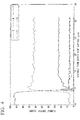
- Fig. 4 is a graph showing the element distributions in the thickness direction of the insulating film of the insulated copper wire obtained in Invention Example 1. White portions in the element mapping image indicate a fluorine atom. From the SEM photograph of Fig. 3A and the element mapping image of a fluorine atom of Fig.
- the fluorine concentration gradient layer was not formed in the insulating film, and the insulating film was a single layer of an insulating layer.
- the structure of the fluorine-containing resin composition layer was confirmed using a SEM-EDS analyzer (manufactured by Hitachi High-Technologies Corporation, electron microscope SU8230). The result is shown in Fig. 5 . From a SEM photograph of Fig. 5 , it was confirmed that the fluorine-containing resin composition layer had a sea-island structure made up of a sea phase 15 including the polyamide-imide and an island phase 16 including the fluororesin dispersed in the sea phase 15.
- the partial discharge inception voltage is high, the adhesion between the insulating film and the conductor is excellent, and a crack is not easily generated, and thus the insulated conductor can be advantageously used as electric coils for a variety of electric devices such as a motor or a transformer.
Landscapes
- Chemical & Material Sciences (AREA)
- Engineering & Computer Science (AREA)
- Organic Chemistry (AREA)
- Materials Engineering (AREA)
- Life Sciences & Earth Sciences (AREA)
- Chemical Kinetics & Catalysis (AREA)
- Wood Science & Technology (AREA)
- Physics & Mathematics (AREA)
- Health & Medical Sciences (AREA)
- Spectroscopy & Molecular Physics (AREA)
- Manufacturing & Machinery (AREA)
- Metallurgy (AREA)
- Electrochemistry (AREA)
- Molecular Biology (AREA)
- Power Engineering (AREA)
- Medicinal Chemistry (AREA)
- Polymers & Plastics (AREA)
- Thermal Sciences (AREA)
- Insulated Conductors (AREA)
- Laminated Bodies (AREA)
- Processes Specially Adapted For Manufacturing Cables (AREA)
- Paints Or Removers (AREA)
- Superconductors And Manufacturing Methods Therefor (AREA)
Abstract
Description
- The present invention relates to an insulated conductor and an insulated conductor manufacturing method.
- Priority is claimed on Japanese Patent Application No.
2017-223536, filed November 21, 2017 2018-215925, filed November 16, 2018 - Insulated conductors obtained by coating a conductor such as a copper wire with an insulating film are used for electric coils for a variety of electric devices such as a motor or a transformer. As a material of the insulating film of the insulated conductor, thermosetting resins, particularly, polyimide-based resins such as a polyamide-imide or a polyimide are broadly used.
- In response to an increase in the power of electric devices in recent years, voltage applied to an insulated conductor tends to increase. Therefore, there is a desire for an insulated conductor in which partial discharge does not easily occur. In order to suppress the occurrence of partial discharge in the insulated conductor, it is effective to increase the partial discharge inception voltage.
- Patent Literature 1 describes, as a method for manufacturing an insulated conductor having a high partial discharge inception voltage, a method in which, when an insulating coating containing a thermosetting resin and a bubble forming agent is applied onto a conductor and baked, the decomposition and evaporation of the bubble forming agent are carried out at the same time as a curing reaction of the thermosetting resin.
- In addition, Patent Literature 2 describes an insulated conductor having an insulating layer that is made up of a thermosetting resin and a fluororesin and in which the mass ratio between the thermosetting resin and the fluororesin is 90:10 to 10:90. In Patent Literature 2, as the insulating layer, a layer formed by mixing a thermosetting resin solution and a fluororesin organosol, applying the obtained liquid mixture onto a conductor, and baking the liquid mixture is used. Patent Literature 2 describes that, when the insulating layer is formed from the liquid mixture obtained by mixing the thermosetting resin solution and the fluororesin organosol, a thermosetting resin and a fluororesin are uniformly dispersed in the insulating layer.
- Patent Literature 3 describes an electric insulated wire in which an insulating film provided on a conductor is formed of at least two kinds of resin components and an interface between the two or more kinds of resins does not have a clear interface, but has an interface having a concentration of the resin component that changes continuously or stepwise. In Patent Literature 3, a fluororesin is described as the resin component. In addition, in Patent Literature 3, as an electric insulated wire manufacturing method, a method including a step of forming an extruded coating layer on the surface of an electric wire provided with a conductor or an insulating layer using a melt obtained by melting and mixing at least two kinds of thermoplastic resins and then, or simultaneously, holding the extruded coating layer for a certain period of time at a temperature lower than the melting point or softening point of a resin having the highest melting point or softening point among the thermoplastic resins by 0°C to 100°C is described.
-
- [Patent Literature 1]
Japanese Unexamined Patent Application, First Publication No.2013-187029 - [Patent Literature 1]
PCT International Publication No. WO2011/024809 - [Patent Literature 1]
Japanese Unexamined Patent Application, First Publication No.2005-259419 - In insulated conductors, the adhesion between a conductor and an insulating film is desirably favorable such that the insulating property of the conductor by the insulating film can be maintained for a long period of time. However, the insulated conductor described in Patent Literature 1 has pores in the insulating film, and thus there is a concern that the adhesion between the conductor and the insulating film may degrade.
- In addition, the addition of a fluororesin to the insulating layer as described in Patent Literature 2 and 3 is effective for the improvement of the lubricity of the surface of the insulating film. However, a fluororesin and resins other than the fluororesin have a low affinity to each other, and thus there is a problem in that a large crack is easily generated between the fluororesin and resins other than the fluororesin.
- The present invention has been made in consideration of the above-described circumstance, and an object of the present invention is to provide an insulated conductor in which partial discharge does not easily occur, the adhesion between an insulating film and a conductor is excellent, and a crack is not easily generated and a manufacturing method thereof.
- In order to achieve the above-described objects, an insulated conductor of the present invention is an insulated conductor including: a conductor; and an insulating film provided on a surface of the conductor, in which the insulating film has a fluorine-containing resin composition layer including a cured product of a thermosetting resin and a fluororesin and a fluorine concentration gradient layer which is disposed between the conductor and the fluorine-containing resin composition layer, includes a cured product of a thermosetting resin and a fluororesin, and is provided with a concentration gradient in which a fluorine atom content decreases from the fluorine-containing resin composition layer side toward the conductor.
- According to the insulated conductor of the present invention configured as described above, the fluorine-containing resin composition layer of the insulating film includes a cured product of a thermosetting resin and a fluororesin, and thus the relative permittivity decreases. Therefore, the partial discharge inception voltage of the insulating film increases. In addition, the fluorine concentration gradient layer disposed between the conductor and the fluorine-containing resin composition layer is provided with a concentration gradient in which the fluorine atom content decreases from the fluorine-containing resin composition layer side toward the conductor, and the fluorine concentration gradient layer has a common composition with the fluorine-containing resin composition layer on the fluorine-containing resin composition layer side, and thus the adhesion to the fluorine-containing resin composition layer becomes favorable, and a crack is not easily generated between the fluorine-containing resin composition layer and the concentration gradient layer. Furthermore, the fluorine-containing resin composition layer and the fluorine concentration gradient layer include a cured product of a thermosetting resin and are thus not easily distorted by heat and are capable of maintaining favorable adhesion between the fluorine-containing resin composition layer and the fluorine concentration gradient layer even at a high temperature. On the other hand, the content of the fluororesin having poor adhesion to the conductor is low on the conductor side of the fluorine concentration gradient layer, and thus the adhesion to the conductor becomes favorable. Therefore, the adhesion between the insulating film and the conductor improves.
- Here, in the insulated conductor of the present invention, it is preferable that the fluororesin included in the fluorine-containing resin composition layer is a thermoplastic resin, and the fluororesin included in the fluorine concentration gradient layer is a thermoplastic resin.
- In this case, the fluororesins included in the fluorine-containing resin composition layer and the fluorine concentration gradient layer have a low surface free energy and have poor compatibility with the thermosetting resin and thus move toward the surface of the insulating film by being heated, and thus the content of the fluororesin on the conductor side of the fluorine concentration gradient layer more reliably decreases, and the adhesion between the insulating film and the conductor becomes more favorable.
- In addition, in the insulated conductor of the present invention, it is preferable that the fluorine-containing resin composition layer has a sea-island structure made up of a sea phase including the cured product of the thermosetting resin and an island phase including the fluororesin dispersed in the sea phase.
- In this case, the fluorine-containing resin composition layer has a discontinuous sea-island structure divided into a sea phase including the cured product of the thermosetting resin and an island phase including the fluororesin, and thus a crack between the cured product of the thermosetting resin and the fluororesin does not easily grow, and the generation of a large crack becomes more difficult.
- In addition, in the insulated conductor of the present invention, it is preferable that a difference between a fluorine atom content at a place with a lowest fluorine atom content in the fluorine concentration gradient layer and a fluorine atom content in a central region in a thickness direction of the fluorine-containing resin composition layer is 10 atom% or more.
- In this case, the fluorine atom content at the place with the lowest fluorine atom content in the fluorine concentration gradient layer is lower than the fluorine atom content in the central region in the thickness direction of the fluorine-containing resin composition layer by 10 atom% or more, and the difference in the fluorine atom content between the fluorine-containing resin composition layer and the fluorine concentration gradient layer becomes large, and thus the adhesion between the insulating film and the conductor reliably improves.
- In addition, in the insulated conductor of the present invention, it is preferable that the fluorine atom content at the place with the lowest fluorine atom content in the fluorine concentration gradient layer is 15 atom% or less.
- In this case, the fluorine atom content at the place with the lowest fluorine atom content in the fluorine concentration gradient layer is as low as 15 atom% or less, and thus the adhesion between the insulating film and the conductor further improves.
- In addition, in the insulated conductor of the present invention, it is preferable that the place with the lowest fluorine atom content in the fluorine concentration gradient layer is in a range of 3 µm or less from the surface of the conductor.
- In this case, the place with the lowest fluorine atom content in the fluorine concentration gradient layer is as close to the surface of the conductor as 3 µm or less, and thus the adhesion between the insulating film and the conductor further improves.
- In addition, in the insulated conductor of the present invention, it is preferable that the fluorine atom content in the central region in the thickness direction of the fluorine-containing resin composition layer is in a range of 20 mass% or more and 70 mass% or less.
- In this case, the fluorine atom content in the fluorine-containing resin composition layer is in a range of 20 mass% or more and 70 mass% or less, and thus the relative permittivity reliably decreases, and the partial discharge inception voltage reliably increases.
- In addition, in the insulated conductor of the present invention, it is preferable that the fluorine-containing resin composition layer and the fluorine concentration gradient layer are a continuous phase.
- In this case, the fluorine-containing resin composition layer and the fluorine concentration gradient layer are a continuous phase, and fluorine-containing resin composition layer and the fluorine concentration gradient layer do not easily exfoliate from each other, and thus the adhesion between the insulating film and the conductor more reliably improves.
- In addition, in the insulated conductor of the present invention, it is preferable that a thickness of the fluorine concentration gradient layer is in a range of 2 µm or more and 15 µm or less.
- In this case, the thickness of the fluorine concentration gradient layer is in a range of 2 µm or more and 15 µm or less, and thus it is possible to improve both the adhesion between the conductor and the fluorine concentration gradient layer and the adhesion between the fluorine concentration gradient layer and the fluorine-containing resin composition layer, whereby it is possible to further improve the adhesion between the insulating film and the conductor.
- An insulated conductor manufacturing method of the present invention is an insulated conductor manufacturing method for manufacturing the above-described insulated conductor, the method comprising: an electrodeposition step of electrodepositing an electrodeposition liquid including thermosetting resin particles and fluororesin particles to a surface of the conductor to obtain an electrodeposition layer-attached conductor; and a drying step of heating and drying the electrodeposition layer-attached conductor at a temperature in a range of (a melting point of the fluororesin particles - 40°C) to (the melting point of the fluororesin particles + 30°C).
- According to the insulated conductor manufacturing method of the present invention configured as described above, in the drying step, the electrodeposition layer-attached conductor is heated at a temperature in a range of (the melting point of the fluororesin particles - 40°C) to (the melting point of the fluororesin particles + 30°C), and thus it is possible to move the fluororesin present on the surface of the conductor to the outside, whereby it is possible to manufacture an insulating film-attached conductor (insulated conductor) having the fluorine-containing resin composition layer and the fluorine concentration gradient layer.
- Here, in the insulated conductor manufacturing method of the present invention, it is preferable that the heating time in the drying step is five minutes or longer.
- In this case, the heating time in the drying step is set to five minutes or longer, and thus it is possible to move a larger amount of the fluororesin present on the surface of the conductor to the outside, whereby it becomes possible to more reliably manufacture an insulated conductor having a fluorine-containing resin composition layer and a fluorine concentration gradient layer.
- According to the present invention, it becomes possible to provide an insulated conductor in which partial discharge does not easily occur, the adhesion between an insulating film and a conductor is excellent, and a crack is not easily generated and a manufacturing method thereof.
-
-
Fig. 1 is a transverse sectional view of an insulated conductor which is an embodiment of the present invention. -
Fig. 2 is a flowchart of an insulated conductor manufacturing method which is an embodiment of the present invention. -
Fig. 3A is a SEM photograph of a cross section of an insulating film of an insulated copper wire obtained in Invention Example 1. -
Fig. 3B is an element mapping image of a fluorine atom in the cross section of the insulating film ofFig. 3A . -
Fig. 4 is a graph showing element distributions in a thickness direction of the insulating film of the insulated copper wire obtained in Invention Example 1. -
Fig. 5 is a SEM photograph of a fluorine-containing resin composition layer configuring the insulating film of the insulated copper wire obtained in Invention Example 1. - Next, an insulated conductor and an insulated conductor manufacturing method which are an embodiment of the present invention will be described with reference to the accompanying drawings.
-
Fig. 1 is a transverse sectional view of an insulated conductor which is an embodiment of the present invention. - An
insulated conductor 10 of the present embodiment has aconductor 11 and an insulatingfilm 12 provided on the surface of theconductor 11 as shown inFig. 1 . - The material of the
conductor 11 is preferably metal having a favorable conductive property such as copper, a copper alloy, aluminum, or an aluminum alloy. Theconductor 11 shown inFig. 1 has a cross section shaped like a round metal wire, but the cross-sectional shape of theconductor 11 is not particularly limited and may be, for example, an elliptical shape or a square shape. In addition, theconductor 11 may be a metal plate. - The insulating
film 12 has a fluorine-containingresin composition layer 13 and a fluorineconcentration gradient layer 14 disposed between theconductor 11 and the fluorine-containingresin composition layer 13. The fluorine-containingresin composition layer 13 includes a cured product of a thermosetting resin and a fluororesin. The fluorineconcentration gradient layer 14 is provided with a concentration gradient in which the fluorine atom content decreases from the fluorine-containingresin composition layer 13 side toward theconductor 11. - The fluorine-containing
resin composition layer 13 has an action of insulating theconductor 11. - The fluorine-containing
resin composition layer 13 includes a cured product of a thermosetting resin and a fluororesin. The fluororesin in the fluorine-containingresin composition layer 13 has an effect for reducing the relative permittivity of the fluorine-containingresin composition layer 13, increasing the partial discharge inception voltage, and suppressing the occurrence of partial discharge. - The fluororesin is preferably a thermoplastic resin having a melting point lower than the decomposition temperature of the cured product of the thermosetting resin. The melting point of the fluororesin is preferably in a range of 250°C or higher and 350°C or lower. The fluororesin may be a homopolymer or a copolymer. As examples of the fluororesin, perfluoroalkoxy fluororesin (PFA), polytetrafluoroethylene (PTFE), and ethylenetetrafluoride-propylene hexafluoride copolymer (FEP) can be exemplified. These fluororesins may be used singly or two or more fluororesins may be used in combination.
- The thermosetting resin is preferably a resin having any one or both of an imide bond and an amide bond. As examples of the thermosetting resin, a polyamide-imide resin, a polyimide resin, a polyamic acid resin, a polyamide resin, a polyether-imide resin, and a polyester-imide resin can be exemplified. These thermosetting resins may be used singly or two or more thermosetting resins may be used in combination. The thermosetting resin is particularly preferably a polyimide-based resin (polyamide-imide resin or polyimide resin) having an imide bond.
- The thickness of the fluorine-containing
resin composition layer 13 is preferably in a range of 5 µm or more and 100 µm or less. When the thickness of the fluorine-containingresin composition layer 13 is in this range, it is possible to reduce the relative permittivity without impairing the flexibility of the insulatingfilm 12. - In the fluorine-containing
resin composition layer 13, the fluorine atom content in a central region in the thickness direction is preferably in a range of 10 atom% or more and 50 atom% or less and more preferably in a range of 20 atom% or more and 40 atom% or less. When the fluorine atom content is in this range, it is possible to reduce the relative permittivity of the fluorine-containingresin composition layer 13 without impairing the flexibility of the insulatingfilm 12. The central region in the thickness direction of the fluorine-containingresin composition layer 13 refers to a range from a location 1/4 of the thickness of the fluorine-containingresin composition layer 13 apart from the center in the thickness direction of the fluorine-containingresin composition layer 13 toward theconductor 11 side to a location 1/4 of the thickness of the fluorine-containingresin composition layer 13 apart from the center toward a side opposite to theconductor 11 side. For example, in a case where the thickness of the fluorine-containingresin composition layer 13 is 40 µm, the central region is a range from alocation 10 µm apart from the center in the thickness direction of the fluorine-containingresin composition layer 13 toward theconductor 11 side to alocation 10 µm apart from the center toward the side opposite to theconductor 11 side. - In the fluorine-containing
resin composition layer 13, the fluorine atom content is preferably uniform. Specifically, the difference between the highest value and the lowest value of the fluorine atom content in the central region in the thickness direction of the fluorine-containingresin composition layer 13 is preferably 5 atom% or less. When the fluorine atom content of the fluorine-containingresin composition layer 13 is uniform, the relative permittivity of the fluorine-containingresin composition layer 13 becomes uniform, and thus partial discharge does not easily occur. - Here, in the present embodiment, the fluorine atom content of the fluorine-containing
resin composition layer 13 refers to the proportion of the number of fluorine atoms in the total number of atoms of all elements included in the fluorine-containingresin composition layer 13. For example, in a case where theconductor 11 is made of copper, and the fluorine-containingresin composition layer 13 is made of a polyamide-imide and a fluororesin, the fluorine atom content refers to the proportion of the number of fluorine (F) atoms in the total number of atoms of fluorine (F), carbon (C), nitrogen (N), oxygen (O), and copper (Cu) included in the fluorine-containingresin composition layer 13. The fluorine atom content in the central region in the thickness direction of the fluorine-containingresin composition layer 13 can be obtained by, for example, linearly analyzing the contents of individual elements along the thickness direction of the fluorine-containingresin composition layer 13 and computing the content of individual elements included in the central region. - The fluorine-containing
resin composition layer 13 preferably has a sea-island structure including a sea phase (matrix phase) including the cured product of the thermosetting resin and an island phase (domain phase) including the fluororesin dispersed in the sea phase. The fact that the fluorine-containingresin composition layer 13 has a sea-island structure can be confirmed using a scanning electron microscope (SEM) and an energy-dispersive X-ray spectroscopy (EDS) analyzer. For example, in a case where a cross section of the fluorine-containingresin composition layer 13 is observed using a SEM-EDS analyzer and a continuous portion from which no fluorine is detected (sea phase) and a portion from which granular fluorine is detected (island shape) are confirmed, it can be said that the fluorine-containingresin composition layer 13 has a sea-island structure. - The shape of the island phase is not particularly limited and can be a spherical shape, an elliptically spherical shape, a conic shape, a polygonal shape, a plate shape, a cylindrical shape, a polygonal column shape, and a shape obtained by combining the above-described shaped. The shape of the island phase may be a neck shape or gourd shape having a narrow necked portion between thick portions. The island phase in the necked shape or the gourd shape has a large contact area with the sea phase and improves in the adhesion to the sea phase, and thus the shape stability of the entire low-
concentration fluorine layer 13 becomes favorable. - The fluorine
concentration gradient layer 14 has an action for improving the adhesion between theconductor 11 and the insulatingfilm 12. - The fluorine
concentration gradient layer 14 includes a thermosetting resin and a fluororesin. The fluorineconcentration gradient layer 14 is provided with a concentration gradient in which the fluorine atom content decreases from the fluorine-containingresin composition layer 13 side toward theconductor 11, and the content of the fluororesin having poor adhesion to theconductor 11 becomes relatively low compared with the fluorineconcentration gradient layer 14, and thus the adhesion between theconductor 11 and the fluorineconcentration gradient layer 14 becomes favorable. In addition, the concentration gradient is provided, and thus the adhesion between the fluorineconcentration gradient layer 14 and the fluorine-containingresin composition layer 13 also becomes favorable. Therefore, the adhesion between theconductor 11 and the insulatingfilm 12 improves. In addition, the thermosetting resin and the fluororesin included in the fluorineconcentration gradient layer 14 are preferably the same as the thermosetting resin and the fluororesin included in the fluorine-containingresin composition layer 13. In addition, the fluorine-containingresin composition layer 13 and the fluorineconcentration gradient layer 14 include the same thermosetting resin and the same fluororesin, whereby the adhesion between the fluorine-containingresin composition layer 13 and the fluorineconcentration gradient layer 14 becomes favorable, and the flexibility improves. - A difference (B-A) when the fluorine atom content at a place with the lowest fluorine atom content in the fluorine concentration gradient layer 14 (hereinafter, also referred to as the "lowest fluorine atom content") is represented by A atom% and the fluorine atom content in a central region in the thickness direction of the fluorine-containing
resin composition layer 13 is represented by B atom% is preferably 10 atom% or more. When this difference (B-A) is less than 10 atom%, there is a concern that the adhesion between theconductor 11 and the fluorineconcentration gradient layer 14 may not sufficiently improve. However, when the difference (A-B) becomes large, there is a concern that the adhesion between the fluorineconcentration gradient layer 14 and the fluorine-containingresin composition layer 13 may degrade. Therefore, the difference (B-A) is preferably 20 atom% or less. - The lowest fluorine atom content in the fluorine
concentration gradient layer 14 can be obtained by, for example, linearly analyzing the contents of individual elements along the thickness direction of the fluorineconcentration gradient layer 14, detecting a place having the lowest content of fluorine, and computing the fluorine atom content. - In addition, the lowest fluorine atom content in the fluorine
concentration gradient layer 14 is preferably 15 atom% or less. When the lowest fluorine atom content in the fluorineconcentration gradient layer 14 exceeds 15 atom%, there is a concern that the adhesion between theconductor 11 and the fluorineconcentration gradient layer 14 may not sufficiently improve. On the other hand, when the lowest fluorine atom content in the fluorineconcentration gradient layer 14 becomes too low, and the difference from the fluorine atom content of the fluorine-containingresin composition layer 13 becomes large, there is a concern that the adhesion between the fluorineconcentration gradient layer 14 and the fluorine-containingresin composition layer 13 may degrade. Therefore, the lowest fluorine atom content in the fluorineconcentration gradient layer 14 is preferably 5 atom% or more. - The place with the lowest fluorine atom content in the fluorine
concentration gradient layer 14 may not be a portion in which the fluorineconcentration gradient layer 14 is in contact with the surface of theconductor 11. That is, in the portion in which the fluorineconcentration gradient layer 14 is in contact with the surface of theconductor 11, the fluorine atom content may be higher than the lowest fluorine atom content. However, when the place with the lowest fluorine atom content in the fluorineconcentration gradient layer 14 is too far away from the surface of theconductor 11, there is a concern that the adhesion between the fluorineconcentration gradient layer 14 and the fluorine-containingresin composition layer 13 may degrade. Therefore, the place with the lowest fluorine atom content in the fluorineconcentration gradient layer 14 is preferably in a range of 3 µm or less from the surface of theconductor 11. - The fluorine-containing
resin composition layer 13 and the fluorineconcentration gradient layer 14 may be a discontinuous phase, but are preferably a continuous phase, that is, the fluorine atom content of the fluorineconcentration gradient layer 14 preferably continuously increases relative to the fluorine atom content of the fluorine-containingresin composition layer 13. - The boundary between the fluorine-containing
resin composition layer 13 and the fluorineconcentration gradient layer 14 is a location at which the concentration of fluorine changes discontinuously in a case where the fluorine-containingresin composition layer 13 and the fluorineconcentration gradient layer 14 are not a continuous phase. In addition, in a case where the fluorine-containingresin composition layer 13 and the fluorineconcentration gradient layer 14 are a continuous phase, the boundary between the fluorine-containingresin composition layer 13 and the fluorineconcentration gradient layer 14 is a location at which the fluorine atom content of the fluorineconcentration gradient layer 14 becomes lower than the fluorine atom content in the central region in the thickness direction of the fluorine-containingresin composition layer 13 by 2 atom%. - The thickness of the fluorine
concentration gradient layer 14 is preferably in a range of 2 µm or more and 15 µm or less. When the thickness of the fluorineconcentration gradient layer 14 is less than 2 µm, there is a concern that it may become difficult to improve both the adhesion between theconductor 11 and the fluorineconcentration gradient layer 14 and the adhesion between the fluorineconcentration gradient layer 14 and the fluorine-containingresin composition layer 13. On the other hand, when the thickness of the fluorineconcentration gradient layer 14 exceeds 15 µm, the effect for improving both the adhesion between theconductor 11 and the fluorineconcentration gradient layer 14 and the adhesion between the fluorineconcentration gradient layer 14 and the fluorine-containingresin composition layer 13 is saturated, and the thickness of the fluorine-containingresin composition layer 13 becomes relatively thin, and thus there is a concern that the relative permittivity of the insulatingfilm 12 may decrease as a whole. -
Fig. 2 is a flowchart of an insulated conductor manufacturing method which is an embodiment of the present invention. - The insulated conductor manufacturing method of the present embodiment includes an electrodeposition step S01 of obtaining an electrodeposition layer-attached conductor by electrodepositing an electrodeposition liquid including thermosetting resin particles and fluororesin particles to a surface of the conductor and a drying step S02 of heating and drying the electrodeposition layer-attached conductor as shown in
Fig. 2 . - In the electrodeposition step S01, an electrodeposition liquid including thermosetting resin particles and thermoplastic fluororesin particles is electrodeposited on the surface of the conductor, thereby obtaining an electrodeposition layer-attached conductor. Here, regarding the electrodeposition liquid, a case where the thermosetting resin particles are polyimide-based resin particles having an imide bond will be described as an example.
- The electrodeposition liquid is made up of a dispersion medium and a solid content. The solid content includes polyimide-based resin particles and fluororesin particles.
- The content proportion of the fluororesin particles in the solid content is preferably in a range of 20 mass% or more and 70 mass% or less and more preferably in a range of 30 mass% or more and 70 mass% or less. In addition, the median diameter of the polyimide-based resin particles is preferably in a range of 50 nm or more and 400 nm or less and more preferably in a range of 50 nm or more and 200 nm or less. In addition, the median diameter of the fluororesin particles is preferably in a range of 50 nm or more and 500 nm or less. Furthermore, the polyimide-based resin particles preferably have a smaller median diameter than the fluororesin particles. Here, the reason for setting the preferred content proportion of the fluororesin particles in the solid content in a range of 20 mass% or more and 70 mass% or less is that, at a content proportion of less than 20 mass%, it is not possible to decrease the relative permittivity of the insulating film, and, at a content proportion of more than 70 mass%, it becomes difficult for the insulating film to form a sea-island structure. In addition, the reason for setting the preferred median diameter of the polyimide-based resin particles in a range of 50 nm or more and 400 nm or less is that, at a median diameter of less than 50 nm, the amount of the dispersion medium present between the resin particles in an electrodeposition layer formed by electrodeposition is small, and the resistance of the electrodeposition layer becomes large, and thus the electrodeposition rate becomes slow, and a long time is required to obtain an electrodeposition layer having a large thickness, and, at a median diameter of more than 400 nm, the dispersion stability of the electrodeposition liquid degrades. Furthermore, the reason for setting the preferred median diameter of the fluororesin particles in a range of 50 nm or more and 500 nm or less is that, at a median diameter of less than 50 nm, the amount of the dispersion medium present between the resin particles in the electrodeposition layer formed by electrodeposition is small, and the resistance of the electrodeposition layer becomes large, and thus the electrodeposition rate becomes slow, and a long time is required to obtain an electrodeposition layer having a large thickness, and, at a median diameter of more than 500 nm, the electrodeposition liquid agglomerate, sedimentation occurs, and the dispersion stability degrades.
- The dispersion medium preferably includes a polar solvent, water, and a base. In addition, the polar solvent preferably has a higher boiling point than water. As the polar solvent, organic solvents such as N-methyl-2-pyrrolidone, 1,3-dimethyl-2-imidazolidinone, dimethyl sulfoxide, and N,N dimethylacetamide are exemplified. Furthermore, as the base, tri-n-propylamine, dibutylamine, piperidine, triethylamine, and the like are exemplified. The content proportion of water in the dispersion medium is preferably in a range of 10 mass% or more and 40 mass% or less and more preferably in a range of 18 mass% or more and 30 mass% or less. In addition, the content proportion of the polar solvent in the dispersion medium is preferably in a range of 60 mass% or more and 90 mass% or less, and the content proportion of the base in the dispersion medium is preferably in a range of 0.01 mass% or more and 0.3 mass% or less. Furthermore, the content proportion of the solid content in the electrodeposition liquid is preferably in a range of 1 mass% or more and 10 mass% or less.
- Here, the reason for setting the preferred content proportion of water in the dispersion medium to 10 mass% or more and 40 mass% or less is that, at a content proportion of less than 10 mass%, the conductivity of the electrodeposition liquid is small, and the electrodeposition layer cannot be formed by electrodeposition, and, at a content proportion of more than 40 mass%, the volatilization rate of the dispersion medium during the drying of the electrodeposition liquid becomes fast, and, when the electrodeposition layer is formed to be thick, bubbles are likely to be generated in the electrodeposition layer. In addition, the reason for setting the preferred content proportion of the polar solvent in the dispersion medium is preferably in a range of 60 mass% or more and 90 mass% or less is that, at a content proportion of less than 60 mass%, the proportion of water in the dispersion medium becomes large, the volatilization rate becomes fast, and bubbles are likely to be generated, and, at a content proportion of more than 90 mass%, the proportion of water in the dispersion medium decreases, the electrodeposition rate becomes slow, and a long time is required to obtain an electrodeposition layer having a thick film. In addition, the reason for setting the preferred content proportion of the base in the dispersion medium in a range of 0.01 mass% or more and 0.3 mass% or less is that, at a content proportion of less than 0.01 mass%, the median diameter of the polyimide-based resin particles increases, and the dispersion stability deteriorates, and, at a content proportion of more than 0.3 mass%, the median diameter of the polyimide-based resin particles decreases, the amount of the dispersion medium present between the resin particles in the electrodeposition layer formed by electrodeposition is small, and the resistance of the electrodeposition layer becomes large, and thus the electrodeposition rate becomes slow, and a long time is required to obtain an electrodeposition layer having a large thickness. Furthermore, the reason for setting the preferred content proportion of the solid content in the electrodeposition liquid in a range of 1 mass% or more and 10 mass% or less is that, at a content proportion of less than 1 mass%, the electrodeposition rate becomes slow, and a long time is required to obtain an electrodeposition layer having a large thickness, and, at a content proportion of more than 10 mass%, the dispersion stability deteriorates. The median diameter of the polyimide-based resin particles and the median diameter of the fluororesin particles are volume-based average particle diameters measured using a dynamic light scattering particle size distribution analyzer (LB-550 manufactured by Horiba, Ltd.).
- Next, a manufacturing method of the electrodeposition liquid will be described.
- First, in a two-liter four-neck flask including a stirrer, a cooling pipe, a nitrogen introduction pipe, and a thermometer, the polar solvent, an isocyanate component, and an acid component are mixed together, heated to a temperature of 80°C to 130°C, held at this temperature for two to eight hours to be reacted with each other, thereby obtaining a polyimide-based resin. Here, as the isocyanate component, aromatic diisocyanates such as diphenylmethane-4,4'-diisocyanate (MDI), diphenylmethane-3,3'-diisocyanate, diphenylmethane-3,4'-diisocyanate, diphenylether-4,4'-diisocyanate, benzophenone-4,4'-diisocyanate, and diphenylsulfone-4,4'-diisocyanate and the like are exemplified, and, as the acid component, trimellitic anhydride (TMA), 1,2,5-trimellitic acid (1,2,5-ETM), biphenyltetracarboxylic dianhydride, benzophenonetetracarboxylic dianhydride, diphenylsulfonetetracarboxylic dianhydride, oxydiphthalic dianhydride (OPDA), pyromellitic dianhydride (PMDA), 4,4'-(2,2'-hexafluoroisopropylidene) diphthalic dianhydride, and the like are exemplified. After that, the polyimide-based resin synthesized above is diluted with the polar solvent, thereby preparing polyimide-based resin varnish.
- Next, the polyimide-based resin varnish obtained above is further diluted with an organic solvent, a basic compound is added thereto, and then water is added thereto at room temperature under stirring. Therefore, a dispersion liquid of polyimide-based resin particles having a median diameter in a range of 50 nm or more and 400 nm or less is obtained.
- A commercially available dispersion of fluororesin particles is diluted with water and then stirred, thereby obtaining a dispersion liquid of fluororesin particles having a median diameter in a range of 50 nm or more and 500 nm or less.
- The dispersion liquid of the polyimide-based resin particles and the dispersion liquid of the fluororesin particles are mixed together, thereby obtaining an electrodeposition liquid.
- As a method for electrodepositing the electrodeposition liquid on the surface of the conductor, it is possible to use a method in which an opposite electrode and the conductor are immersed in the electrodeposition liquid, and then a direct-current voltage is applied using the opposite electrode as a negative electrode and the conductor as a positive electrode. The direct-current voltage applied is preferably in a range of 1 V or higher and 600 V or lower. The temperature of the electrodeposition liquid during the application of the direct-current voltage is preferably in a range of 5°C or higher and 40°C or lower. The application time of the direct-current voltage is preferably in a range of 0.01 seconds or longer and 300 seconds or shorter.
- In the drying step S02, the electrodeposition layer-attached conductor obtained in the electrodeposition step S01 is heated, and the electrodeposition layer is dried to form an insulating film, thereby obtaining an insulating film-attached conductor (insulated conductor). The drying atmosphere of the electrodeposition layer-attached conductor is not particularly limited and may be an atmospheric atmosphere or an inert atmosphere.
- The drying temperature is a temperature in a range of (the melting point of the fluororesin particles - 40°C) to (the melting point of the fluororesin particles + 30°C). In addition, the drying temperature is preferably in a range of 300°C or higher and 350°C or lower. When the electrodeposition layer-attached conductor is heated at this temperature, the fluororesin particles in the electrodeposition layer melt or soften, and the fluororesin present on the surface of the conductor moves to the outside, whereby a fluorine concentration gradient layer is generated. The drying time fluctuates depending on factors such as the drying temperature, the size of the conductor, and the thickness of the electrodeposition layer, but is generally in a range of five minutes or longer and 10 minutes or shorter.
- In addition, in the drying step S02, the electrodeposition layer-attached conductor may be dried at a temperature lower than the melting point of the fluororesin particle of 200°C by less than 40°C as preliminary drying before heated at a temperature in a range of (the melting point of the fluororesin particles - 40°C) to (the melting point of the fluororesin particles + 30°C). When the preliminary drying temperature is in this range, it is possible to efficiently dry the electrodeposition layer without moving the fluororesin particles to the surface of the film. The preliminary drying and the subsequent drying are preferably continuously carried out using the same heating device. The preliminary drying time fluctuates depending on factors such as the drying temperature, the size of the conductor, and the thickness of the electrodeposition layer, but is generally in a range of one minute or longer and 10 minutes or shorter, preferably five minutes or longer, and particularly preferably in a range of five minutes or longer and 10 minutes or shorter.
- According to the
insulated conductor 10 of the present embodiment configured as described above, the fluorine-containingresin composition layer 13 of the insulatingfilm 12 includes the cured product of the thermosetting resin and the fluororesin, and thus the relative permittivity decreases. Therefore, the partial discharge inception voltage of the insulatingfilm 12 becomes high. In addition, the fluorineconcentration gradient layer 14 disposed between theconductor 11 and the fluorine-containingresin composition layer 13 is provided with the concentration gradient in which the fluorine atom content decreases from the fluorine-containing resin composition layer side toward the conductor, and the fluorineconcentration gradient layer 14 has a common composition with the fluorine-containingresin composition 13 on the fluorine-containingresin composition layer 13 side, and thus the adhesion to the fluorine-containingresin composition layer 13 becomes favorable, and a crack is not easily generated between the fluorine-containingresin composition layer 13 and the fluorineconcentration gradient layer 14. Furthermore, the fluorine-containingresin composition layer 13 and the fluorineconcentration gradient layer 14 include the cured product of the thermosetting resin and are thus not easily distorted by heat and are capable of maintaining favorable adhesion between the fluorine-containingresin composition layer 13 and the fluorineconcentration gradient layer 14 even at a high temperature. On the other hand, the content of the fluororesin having poor adhesion to theconductor 11 is low on theconductor 11 side, and thus the adhesion to theconductor 11 becomes favorable. Therefore, the adhesion between the insulatingfilm 12 and theconductor 11 improves. - In the
insulated conductor 10 of the present embodiment, the thermoplastic resin is used as the fluororesins included in the fluorine-containingresin composition layer 13 and the fluorineconcentration gradient layer 14, whereby heating facilitates the movement of the fluororesins toward the surface side of the insulatingfilm 11, and thus the content of the fluororesin on theconductor 11 side of the fluorineconcentration gradient layer 14 more reliably becomes low, and it is possible to make the adhesion between the insulating film and the conductor more favorable. - In the
insulated conductor 10 of the present embodiment, the fluorine-containingresin composition layer 13 is provided with a discontinuous sea-island structure made up of the sea phase including the cured product of the thermosetting resin and the island phase including the fluororesin dispersed in the sea phase, whereby a crack between the cured product of the thermosetting resin and the fluororesin in the fluorine-containingresin composition layer 13 does not easily grow, and it is possible to make the generation of a large crack more difficult. - In the
insulated conductor 10 of the present embodiment, the fluorine atom content at the place with the lowest fluorine atom content in the fluorineconcentration gradient layer 14 is set to be lower than the fluorine atom content in the central region in the thickness direction of the fluorine-containing resin composition layer by 10 atom% or more to increase the difference in the fluorine atom content between the fluorine-containingresin composition layer 13 and the fluorineconcentration gradient layer 14, whereby it is possible to reliably improve the adhesion between the insulatingfilm 12 and theconductor 11. - In the
insulated conductor 10 of the present embodiment, the fluorine atom content at the place with the lowest fluorine atom content in the fluorineconcentration gradient layer 14 is set to 15 atom% or less, whereby it is possible to further improve the adhesion between the insulatingfilm 12 and theconductor 11. - In the
insulated conductor 10 of the present embodiment, the place with the lowest fluorine atom content in the fluorineconcentration gradient layer 14 is formed as close to the surface of theconductor 11 as 3 µm or less, whereby it is possible to further improve the adhesion between the insulatingfilm 12 and theconductor 11. - In the
insulated conductor 10 of the present embodiment, the fluorine atom content in the central region in the thickness direction of the fluorine-containingresin composition layer 13 is set in a range of 20 mass% or more and 70 mass% or less, whereby it is possible to reliably decrease the relative permittivity, and thus it is possible to reliably increase the partial discharge inception voltage. - In the
insulated conductor 10 of the present embodiment, the fluorine-containingresin composition layer 13 and the fluorineconcentration gradient layer 14 are formed as a continuous phase to make the fluorine-containingresin composition layer 13 and the fluorineconcentration gradient layer 14 not easily exfoliate from each other, whereby it is possible to further improve the adhesion between the insulatingfilm 12 and theconductor 11. - In the
insulated conductor 10 of the present embodiment, the thickness of the fluorineconcentration gradient layer 14 is set in a range of 2 µm or more and 15 µm or less, whereby it is possible to improve both the adhesion between theconductor 11 and the fluorineconcentration gradient layer 14 and the adhesion between the fluorineconcentration gradient layer 14 and the fluorine-containingresin composition layer 13, and thus it is possible to further improve the adhesion between the insulatingfilm 12 and theconductor 11. - In addition, according to the insulated conductor manufacturing method of the present embodiment, in the drying step S02, the electrodeposition layer-attached conductor is heated and dried at a temperature in a range of (the melting point of the fluororesin particles - 40°C) to (the melting point of the fluororesin particles + 30°C), and thus it is possible to move the fluororesin present on the surface of the conductor to the outside, whereby it is possible to manufacture an insulating film-attached conductor (insulated conductor) having the fluorine-containing
resin composition layer 13 and the fluorineconcentration gradient layer 14. - Furthermore, in the insulated conductor manufacturing method of the present embodiment, the heating time in the drying step S02 is set to five minutes or longer, and thus it is possible to move a larger amount of the fluororesin present on the surface of the conductor to the outside, whereby it becomes possible to more reliably manufacture an insulated conductor having a fluorine-containing resin composition layer and a fluorine concentration gradient layer.
- Hitherto, the embodiment of the present invention has been described, but the present invention is not limited thereto and can be appropriately modified within the scope of the technical concept of the invention.
- For example, in the
insulated conductor 10 of the present embodiment shown inFig. 1 , the fluorineconcentration gradient layer 14 is formed so as to cover the entire surface of theconductor 11, but the configuration is not limited to this case. Specifically, the fluorineconcentration gradient layer 14 may be formed so as to be in contact with a part of the surface of theconductor 11. In addition, in theinsulated conductor 10 of the present embodiment, an adhesive layer may also be provided between theconductor 11 and the insulatingfilm 12 in order to further improve the adhesion between theconductor 11 and the insulatingfilm 12. The adhesive layer is preferably a layer singly including the thermosetting resin included in the insulatingfilm 12. - In addition, in order to improve the lubricity of the
insulated conductor 10, a high-concentration fluorine-containing resin composition layer including a thermosetting resin and a fluororesin and having a fluorine atom content relatively higher than that of the fluorine-containingresin composition layer 13 may also be provided on the outer circumferential surface of the fluorine-containingresin composition layer 13 of the insulatingfilm 12. Furthermore, a fluororesin-only layer singly including a fluororesin may also be provided on the outer circumferential surface of the high-concentration fluorine-containing resin composition layer. - Next, the action and effect of the present invention will be described in more detail using examples.
- First, in a two-liter four-neck flask including a stirrer, a cooling pipe, a nitrogen introduction pipe, and a thermometer, N-methyl-2-pyrrolidone (747 g) as an organic solvent, 4,4'-diphenylmethane isocyanate (298 g, 1.19 mol) as an isocyanate component, and trimellitic anhydride (227 g, 1.18 mol) as an acid component were injected and heated up to 130°C. The components were reacted at this temperature for approximately four hours, thereby obtaining a polyamide-imide resin (PAI) having a number-average molecular weight of 17,000. After that, the polyamide-imide resin synthesized above was diluted using N-methyl-2-pyrrolidone as an organic solvent such that the concentration of the polyamide-imide resin (non-volatile component) reached 20 mass%, thereby obtaining polyamide-imide varnish (polyamide-imide resin:N-methyl-2-pyrrolidone = 20 mass%:80 mass%).
- Next, the polyamide-imide varnish obtained above (62.5 g) was further diluted with N-methyl-2-pyrrolidone (140 g), tri-n-propylamine (0.5 g) which is a basic compound was added thereto, and then, while stirring this liquid at a high speed of a rotation speed of 10,000 rpm, water (47 g) was added thereto at normal temperature (25°C). Therefore, a dispersion liquid of polyamide-imide resin particles having a median diameter of 160 nm (polyamide-imide resin particles:N-methyl-2-pyrrolidone:water:tri-n-propylamine = 5 mass%:76 mass%:18.8 mass%:0.2 mass%) (250 g) was obtained.
- A commercially available perfluoroalkoxy fluororesin (PFA) dispersion was diluted with water and then stirred, thereby obtaining a PFA particle dispersion (median diameter: 200 nm, PFA particle:water = 30 mass%:70 mass%).
- The polyamide-imide resin (PAI) particle dispersion liquid (60 g) and the fluororesin (PFA) particle dispersion liquid (10 g) were mixed together, thereby obtaining an electrodeposition liquid (PAI particles:PFA particles:N-methyl-2-pyrrolidone:water:tri-n-propylamine = 4.3 mass%:4.3 mass%:65 mass%:26.2 mass%:0.2 mass%).
- An insulated copper wire was produced using the electrodeposition liquid prepared above. Specifically, first, the electrodeposition liquid was retained in an electrodeposition tank, and the temperature of the electrodeposition liquid in this electrodeposition tank was set to 20°C. Next, in a state in which a copper wire (conductor) having a length of 300 mm and a diameter of 1 mm was used as a positive electrode, a cylindrical copper plate inserted into the electrodeposition liquid in the electrodeposition tank was used as a negative electrode, and a direct-current voltage of 100 V was applied between the copper wire and the cylindrical copper plate, the copper wire and the cylindrical copper plate were held in the electrodeposition liquid in the electrodeposition tank for 30 seconds. Therefore, an electrodeposition layer-attached copper wire having an electrodeposition layer formed on the surface of the copper wire was obtained. Next, the electrodeposition layer-attached copper wire was injected into a muffle furnace and heated under conditions of being heated at 250°C for five minutes and then heated at 300°C for five minutes to dry the electrodeposition layer, thereby obtaining a copper wire having an insulating film having a thickness of 45 µm formed on a surface. This insulating film-attached copper wire (insulated copper wire) was regarded as Invention Example 1.
- An insulated copper wire of Comparative Example 1 having an insulating film having a thickness of 45 µm formed on a surface was obtained in the same manner as in Invention Example 1 except for the fact that the electrodeposition layer-attached copper wire was heated at 250°C for five minutes and then not heated at 300°C.
- An insulated copper wire of Comparative Example 2 having an insulating film having a thickness of 45 µm formed on a surface was obtained in the same manner as in Invention Example 1 except for the fact that a polyimide-based resin particle dispersion liquid was used as the electrodeposition liquid instead of the electrodeposition liquid for fluororesin and polyamide-imide resin-complexed coating and the electrodeposition layer-attached copper wire was heated at 250°C for five minutes and then not heated at 300°C.
- For the obtained insulated copper wires (insulated conductors), the element distributions and fluorine atom contents of the insulating film, the friction coefficient, and the flexibility were measured using the following methods.
- The copper wire was buried in a resin and polished to obtain a cross section, and then a SEM photograph of the insulating film cross section of the insulated copper wire and an element mapping image of the fluorine atom in the insulating film cross section were captured using a SEM-EDS analyzer (manufactured by Hitachi High-Technologies Corporation, electron microscope SU8230). In addition, from the obtained SEM photograph and element mapping image, whether or not the fluorine-containing resin composition layer and the fluorine concentration gradient layer were formed in the insulating film or whether or not the fluorine concentration gradient layer was not formed and the insulating film was a single layer of an insulating layer (fluorine-containing resin composition layer) was confirmed. In addition, regarding individual elements of fluorine (F), carbon (C), nitrogen (N), oxygen (O), and copper (Cu) in the insulating film of the insulated copper wire, the element contents in the case of regarding the total number of atoms as 100 atom% were linearly analyzed, and the element distributions in the thickness direction of the insulating film were confirmed. In addition, the thickness of the fluorine concentration gradient layer was measured from the fluorine contents obtained by the linear analysis, the lowest fluorine atom content of the fluorine concentration gradient layer was extracted, and the fluorine content of the insulating layer (fluorine-containing resin composition layer) was computed. As the fluorine content of the insulating layer, the average value of the fluorine contents in the central region of the insulating layer was used. The results are shown in
Fig. 3 ,Fig. 4 , and Table 1. - The relative permittivity was obtained by computing the permittivity from the electrostatic capacity of the insulating film and the film thickness of the insulating film using an LCR meter (manufactured by Hioki E. E. Corporation) and dividing this permittivity by the permittivity ε0 (8.85 x 10⁻¹² F/m) of a vacuum. The film thickness of the insulating film was measured using a micrometer (manufactured by Mitutoyo Corporation). The results are shown in Table 1.
- The adhesion was measured on the basis of "5.5 Adhesion test" of a method regulated by JIS C 3216-3 (Winding wires - Test methods - Part 3: Mechanical properties). A cut reaching the surface of the copper wire from the surface of the insulating film was provided in the center in the length direction of the insulated copper wire (length: 300 mm, diameter: 1 mm), then, the test specimen was stretched using a precision universal/tensile tester (manufactured by Shimadzu Corporation, AUTOGRAPH AGS-10kNX) at a speed of 5±1 mm per second such that the stretch ratio reached 15%, then, the surrounding of the cut provided to the insulated copper wire was observed, and the length of the insulating film floating from the copper wire (floating length) was measured. The floating lengths were measured throughout the entire surface of the insulated copper wire, and the maximum length of the measured floating lengths was shown in Table 1.
[Table 1] Composition of electrodeposition liquid Drying condition of electrodeposition layer-attached copper wire Evaluation Thermosetting resin particles Fluororesin particles Fluorine concentration gradient layer Insulating layer Relative permittivity Adhesion (floating length) (mm) Kind Content (mass%) Kind Content (mass%) Melting point (°C) Thickness (µm) Lowest fluorine atom content (atom%) Fluorine atom content (atom%) Invention Example 1 PAI 99.5 PFA 0.5 310 250°C x 5 minutes → 300°C x 5 minutes 8 11 24 2.9 2 Comparative Example 1 PAI 99.5 PFA 0.5 310 250°C x 5 minutes Fluorine concentration gradient layer not formed 29 3.4 4 Comparative Example 2 PAI 100 Fluororesin particles not added 250°C x 5 minutes - - - 4.7 2 -
Fig. 3A is a SEM photograph of the insulating film cross section of the insulated copper wire obtained in Invention Example 1, andFig. 3B is an element mapping image of a fluorine atom in the insulating film cross section.Fig. 4 is a graph showing the element distributions in the thickness direction of the insulating film of the insulated copper wire obtained in Invention Example 1. White portions in the element mapping image indicate a fluorine atom. From the SEM photograph ofFig. 3A and the element mapping image of a fluorine atom ofFig. 3B , in the insulated copper wire obtained in Invention Example 1, the formation of the fluorine-containingresin composition layer 13 and the fluorineconcentration gradient layer 14 disposed between theconductor 11 and the fluorine-containingresin composition layer 13 in the insulatingfilm 12 was confirmed. In addition, from the graph ofFig. 4 , it was confirmed that, in the fluorine-containing resin composition layer and the fluorine concentration gradient layer, the distributions of the individual elements changed continuously, and a continuous phase was formed. In contrast, in the insulated copper wire obtained in Comparative Example 1 in which the drying temperature of the electrodeposition layer-attached copper wire was as low as 250°C (the melting point of PFA particles - 60°C), the fluorine concentration gradient layer was not formed in the insulating film, and the insulating film was a single layer of an insulating layer. - In addition, as shown in Table 1, when the insulated copper wire of Comparative Example 1 provided with the single layer of the insulating film including the polyamide-imide resin and the fluororesin and the insulated copper wire of Comparative Example 2 provided with the single layer of the insulating film singly including the polyamide-imide resin are compared with each other, the relative permittivity became lower in the insulated copper wire of Comparative Example 1. On the other hand, it was confirmed that, regarding the adhesion, the floating length was shorter and more favorable in the insulated copper wire of Comparative Example 2.
- In contrast, it was confirmed that, in the insulated copper wire of Invention Example 1 in which the insulating film had the fluorine concentration gradient layer, the relative permittivity was, similar to the insulated copper wire of Comparative Example 1, suppressed to be low, and the adhesion was, similar to the insulated copper wire of Comparative Example 2, favorable.
- For the insulated copper wire of Invention Example 1, the structure of the fluorine-containing resin composition layer was confirmed using a SEM-EDS analyzer (manufactured by Hitachi High-Technologies Corporation, electron microscope SU8230). The result is shown in
Fig. 5 . From a SEM photograph ofFig. 5 , it was confirmed that the fluorine-containing resin composition layer had a sea-island structure made up of asea phase 15 including the polyamide-imide and anisland phase 16 including the fluororesin dispersed in thesea phase 15. - In the insulated conductor of the present invention, the partial discharge inception voltage is high, the adhesion between the insulating film and the conductor is excellent, and a crack is not easily generated, and thus the insulated conductor can be advantageously used as electric coils for a variety of electric devices such as a motor or a transformer. In addition, it is possible to manufacture in an industrially advantageous manner an insulated conductor in which the partial discharge inception voltage is high, the adhesion between the insulating film and the conductor is excellent, and a crack is not easily generated using the insulated conductor manufacturing method of the present invention.
-
- 10
- Insulated conductor
- 11
- Conductor
- 12
- Insulating film
- 13
- Fluorine-containing resin composition layer
- 14
- Fluorine concentration gradient layer
- 15
- Sea phase
- 16
- Island phase
Claims (11)
- An insulated conductor comprising:a conductor; andan insulating film provided on a surface of the conductor,wherein the insulating film includes a fluorine-containing resin composition layer including a cured product of a thermosetting resin and a fluororesin and a fluorine concentration gradient layer which is disposed between the conductor and the fluorine-containing resin composition layer, includes a cured product of a thermosetting resin and a fluororesin, and is provided with a concentration gradient in which a fluorine atom content decreases from the fluorine-containing resin composition layer side toward the conductor.
- The insulated conductor according to Claim 1,
wherein the fluororesin included in the fluorine-containing resin composition layer is a thermoplastic resin, and the fluororesin included in the fluorine concentration gradient layer is a thermoplastic resin. - The insulated conductor according to Claim 1 or 2,
wherein the fluorine-containing resin composition layer has a sea-island structure made up of a sea phase including the cured product of the thermosetting resin and an island phase including the fluororesin dispersed in the sea phase. - The insulated conductor according to any one of Claims 1 to 3,
wherein a difference between a fluorine atom content at a place with a lowest fluorine atom content in the fluorine concentration gradient layer and a fluorine atom content in a central region in a thickness direction of the fluorine-containing resin composition layer is 10 atom% or more. - The insulated conductor according to any one of Claims 1 to 4,
wherein a fluorine atom content at a place with a lowest fluorine atom content in the fluorine concentration gradient layer is 15 atom% or less. - The insulated conductor according to any one of Claims 1 to 5,
wherein a place with a lowest fluorine atom content in the fluorine concentration gradient layer is in a range of 3 µm or less from the surface of the conductor. - The insulated conductor according to any one of Claims 1 to 6,
wherein a fluorine atom content in a central region in a thickness direction of the fluorine-containing resin composition layer is in a range of 20 mass% or more and 70 mass% or less. - The insulated conductor according to any one of Claims 1 to 7,
wherein the fluorine-containing resin composition layer and the fluorine concentration gradient layer are a continuous phase. - The insulated conductor according to any one of Claims 1 to 8,
wherein a thickness of the fluorine concentration gradient layer is in a range of 2 µm or more and 15 µm or less. - An insulated conductor manufacturing method for manufacturing the insulated conductor according to any one of Claims 1 to 9, the method comprising:an electrodeposition step of electrodepositing an electrodeposition liquid including thermosetting resin particles and fluororesin particles to a surface of the conductor to obtain an electrodeposition layer-attached conductor; anda drying step of heating and drying the electrodeposition layer-attached conductor at a temperature in a range of (a melting point of the fluororesin particles - 40°C) to (the melting point of the fluororesin particles + 30°C).
- The insulated conductor manufacturing method according to Claim 10,
wherein a heating time in the drying step is five minutes or longer.
Applications Claiming Priority (3)
| Application Number | Priority Date | Filing Date | Title |
|---|---|---|---|
| JP2017223536 | 2017-11-21 | ||
| JP2018215925A JP6508406B1 (en) | 2017-11-21 | 2018-11-16 | Insulated conductor and method of manufacturing insulated conductor |
| PCT/JP2018/042816 WO2019102991A1 (en) | 2017-11-21 | 2018-11-20 | Insulated conductor and insulated conductor manufacturing method |
Publications (2)
| Publication Number | Publication Date |
|---|---|
| EP3716293A1 true EP3716293A1 (en) | 2020-09-30 |
| EP3716293A4 EP3716293A4 (en) | 2021-08-11 |
Family
ID=66429820
Family Applications (1)
| Application Number | Title | Priority Date | Filing Date |
|---|---|---|---|
| EP18880525.3A Pending EP3716293A4 (en) | 2017-11-21 | 2018-11-20 | Insulated conductor and insulated conductor manufacturing method |
Country Status (7)
| Country | Link |
|---|---|
| US (1) | US11430585B2 (en) |
| EP (1) | EP3716293A4 (en) |
| JP (1) | JP6508406B1 (en) |
| KR (1) | KR102590076B1 (en) |
| CN (1) | CN111418030B (en) |
| TW (1) | TWI787399B (en) |
| WO (1) | WO2019102991A1 (en) |
Families Citing this family (3)
| Publication number | Priority date | Publication date | Assignee | Title |
|---|---|---|---|---|
| JP7375777B2 (en) * | 2021-01-13 | 2023-11-08 | 三菱マテリアル株式会社 | Electrodeposition liquid, manufacturing method of insulation film |
| JP2022148149A (en) * | 2021-03-24 | 2022-10-06 | 三菱マテリアル株式会社 | Insulative coating-attached flat plate conductive plate, and manufacturing method thereof |
| CN113793718B (en) * | 2021-08-23 | 2024-01-09 | 湖南兴威新材料有限公司 | Thin film electrode and preparation method and application thereof |
Family Cites Families (17)
| Publication number | Priority date | Publication date | Assignee | Title |
|---|---|---|---|---|
| JPH0237619A (en) * | 1988-07-27 | 1990-02-07 | Showa Electric Wire & Cable Co Ltd | Environment-resistant cable |
| JP2001508588A (en) * | 1997-01-14 | 2001-06-26 | レイケム・コーポレイション | Insulated electrical conductor |
| JPH10334739A (en) * | 1997-05-30 | 1998-12-18 | Hitachi Cable Ltd | Wire/cable covered with elastomer and its manufacture |
| KR100572646B1 (en) * | 1998-07-17 | 2006-04-24 | 제이에스알 가부시끼가이샤 | A Polyimide-type Composite and Electronic Elements Using the Same, and Aqueous Polyimide-type Dispersions |
| JP2001294815A (en) * | 2000-04-13 | 2001-10-23 | Jsr Corp | Aqueous dispersion for forming low-dielectric constant insulation film, the resultant low-dielectric constant insulation film, and electronic component |
| JP2002298674A (en) | 2001-03-29 | 2002-10-11 | Mitsubishi Cable Ind Ltd | Manufacturing method of insulation wire and insulation wire |
| JP2003151754A (en) * | 2001-11-08 | 2003-05-23 | Matsushita Electric Ind Co Ltd | Induction heating apparatus |
| JP2005259419A (en) | 2004-03-10 | 2005-09-22 | Matsushita Electric Ind Co Ltd | Insulated cable and its manufacturing method |
| JP2006004681A (en) * | 2004-06-16 | 2006-01-05 | Totoku Electric Co Ltd | Colored fusion electric wire suitable at thermometry |
| JP2010100905A (en) * | 2008-10-24 | 2010-05-06 | Tokai Rubber Ind Ltd | Si-CONTAINING CARBON FILM AND DIE USING THE SAME |
| JP2011071089A (en) * | 2009-08-24 | 2011-04-07 | Daikin Industries Ltd | Electric wire and method of manufacturing the same |
| WO2011024809A1 (en) | 2009-08-24 | 2011-03-03 | ダイキン工業株式会社 | Electric wire and process for production thereof |
| US9075213B2 (en) * | 2011-09-14 | 2015-07-07 | Mitsubishi Rayon Co., Ltd. | Plastic optical fiber cable |
| JP2013187029A (en) | 2012-03-07 | 2013-09-19 | Furukawa Electric Co Ltd:The | Method for manufacturing insulated electric wire having bubble therein |
| CN205542046U (en) * | 2015-03-31 | 2016-08-31 | 日立金属株式会社 | Insulated wire, magnetism shielded cable , magnetic screen pipe and magnetic screen piece |
| JP6700996B2 (en) | 2016-06-15 | 2020-05-27 | 本田技研工業株式会社 | Battery state estimating device and battery state estimating method |
| JP2019096606A (en) | 2017-11-21 | 2019-06-20 | 三菱マテリアル株式会社 | Insulated conductor and method for manufacturing insulated conductor |
-
2018
- 2018-11-16 JP JP2018215925A patent/JP6508406B1/en active Active
- 2018-11-20 KR KR1020207014087A patent/KR102590076B1/en active IP Right Grant
- 2018-11-20 WO PCT/JP2018/042816 patent/WO2019102991A1/en unknown
- 2018-11-20 CN CN201880074817.XA patent/CN111418030B/en active Active
- 2018-11-20 EP EP18880525.3A patent/EP3716293A4/en active Pending
- 2018-11-20 US US16/758,505 patent/US11430585B2/en active Active
- 2018-11-21 TW TW107141422A patent/TWI787399B/en active
Also Published As
| Publication number | Publication date |
|---|---|
| CN111418030B (en) | 2021-09-10 |
| CN111418030A (en) | 2020-07-14 |
| JP6508406B1 (en) | 2019-05-08 |
| TWI787399B (en) | 2022-12-21 |
| TW201928997A (en) | 2019-07-16 |
| KR102590076B1 (en) | 2023-10-16 |
| WO2019102991A1 (en) | 2019-05-31 |
| EP3716293A4 (en) | 2021-08-11 |
| US20200251255A1 (en) | 2020-08-06 |
| KR20200090159A (en) | 2020-07-28 |
| US11430585B2 (en) | 2022-08-30 |
| JP2019096607A (en) | 2019-06-20 |
Similar Documents
| Publication | Publication Date | Title |
|---|---|---|
| EP3716292A1 (en) | Insulated conductor and insulated conductor manufacturing method | |
| EP3716293A1 (en) | Insulated conductor and insulated conductor manufacturing method | |
| KR102545341B1 (en) | Electrodeposition liquid and method for producing a conductor with an insulating coating using the same | |
| Yanashima et al. | Effects of addition of MgO fillers with various sizes and co-addition of nano-sized SiO2 fillers on the dielectric properties of epoxy resin | |
| CN108431905B (en) | Insulated wire | |
| WO2022154052A1 (en) | Electrodeposition fluid and method for producing insulating coating film | |
| JP6912253B2 (en) | Manufacturing method of insulated wire | |
| EP4318505A1 (en) | Insulation film-provided flat conductive plate and method for manufacturing same |
Legal Events
| Date | Code | Title | Description |
|---|---|---|---|
| STAA | Information on the status of an ep patent application or granted ep patent |
Free format text: STATUS: THE INTERNATIONAL PUBLICATION HAS BEEN MADE |
|
| PUAI | Public reference made under article 153(3) epc to a published international application that has entered the european phase |
Free format text: ORIGINAL CODE: 0009012 |
|
| STAA | Information on the status of an ep patent application or granted ep patent |
Free format text: STATUS: REQUEST FOR EXAMINATION WAS MADE |
|
| 17P | Request for examination filed |
Effective date: 20200427 |
|
| AK | Designated contracting states |
Kind code of ref document: A1 Designated state(s): AL AT BE BG CH CY CZ DE DK EE ES FI FR GB GR HR HU IE IS IT LI LT LU LV MC MK MT NL NO PL PT RO RS SE SI SK SM TR |
|
| AX | Request for extension of the european patent |
Extension state: BA ME |
|
| DAV | Request for validation of the european patent (deleted) | ||
| DAX | Request for extension of the european patent (deleted) | ||
| A4 | Supplementary search report drawn up and despatched |
Effective date: 20210712 |
|
| RIC1 | Information provided on ipc code assigned before grant |
Ipc: H01B 7/02 20060101AFI20210707BHEP Ipc: H01B 13/00 20060101ALI20210707BHEP Ipc: H01B 13/16 20060101ALI20210707BHEP Ipc: H01F 5/06 20060101ALI20210707BHEP Ipc: C08G 73/14 20060101ALI20210707BHEP Ipc: C08L 79/08 20060101ALI20210707BHEP Ipc: C09D 5/44 20060101ALI20210707BHEP Ipc: C09D 127/12 20060101ALI20210707BHEP Ipc: H01B 3/30 20060101ALI20210707BHEP Ipc: H01B 7/04 20060101ALI20210707BHEP Ipc: H01B 3/44 20060101ALI20210707BHEP Ipc: C09D 7/65 20180101ALI20210707BHEP Ipc: C09D 201/00 20060101ALI20210707BHEP Ipc: C25D 13/00 20060101ALI20210707BHEP |
|
| STAA | Information on the status of an ep patent application or granted ep patent |
Free format text: STATUS: EXAMINATION IS IN PROGRESS |
|
| 17Q | First examination report despatched |
Effective date: 20240209 |