EP3716291A1 - Fasergewebter isolator für einen elektrischen generator - Google Patents
Fasergewebter isolator für einen elektrischen generator Download PDFInfo
- Publication number
- EP3716291A1 EP3716291A1 EP19210458.6A EP19210458A EP3716291A1 EP 3716291 A1 EP3716291 A1 EP 3716291A1 EP 19210458 A EP19210458 A EP 19210458A EP 3716291 A1 EP3716291 A1 EP 3716291A1
- Authority
- EP
- European Patent Office
- Prior art keywords
- electric generator
- rotating portion
- generator
- coolant
- woven
- Prior art date
- Legal status (The legal status is an assumption and is not a legal conclusion. Google has not performed a legal analysis and makes no representation as to the accuracy of the status listed.)
- Granted
Links
Images


Classifications
-
- H—ELECTRICITY
- H02—GENERATION; CONVERSION OR DISTRIBUTION OF ELECTRIC POWER
- H02K—DYNAMO-ELECTRIC MACHINES
- H02K3/00—Details of windings
- H02K3/04—Windings characterised by the conductor shape, form or construction, e.g. with bar conductors
- H02K3/24—Windings characterised by the conductor shape, form or construction, e.g. with bar conductors with channels or ducts for cooling medium between the conductors
-
- H—ELECTRICITY
- H02—GENERATION; CONVERSION OR DISTRIBUTION OF ELECTRIC POWER
- H02K—DYNAMO-ELECTRIC MACHINES
- H02K3/00—Details of windings
- H02K3/32—Windings characterised by the shape, form or construction of the insulation
-
- H—ELECTRICITY
- H01—ELECTRIC ELEMENTS
- H01B—CABLES; CONDUCTORS; INSULATORS; SELECTION OF MATERIALS FOR THEIR CONDUCTIVE, INSULATING OR DIELECTRIC PROPERTIES
- H01B3/00—Insulators or insulating bodies characterised by the insulating materials; Selection of materials for their insulating or dielectric properties
- H01B3/18—Insulators or insulating bodies characterised by the insulating materials; Selection of materials for their insulating or dielectric properties mainly consisting of organic substances
- H01B3/48—Insulators or insulating bodies characterised by the insulating materials; Selection of materials for their insulating or dielectric properties mainly consisting of organic substances fibrous materials
-
- H—ELECTRICITY
- H02—GENERATION; CONVERSION OR DISTRIBUTION OF ELECTRIC POWER
- H02K—DYNAMO-ELECTRIC MACHINES
- H02K1/00—Details of the magnetic circuit
- H02K1/06—Details of the magnetic circuit characterised by the shape, form or construction
- H02K1/22—Rotating parts of the magnetic circuit
- H02K1/32—Rotating parts of the magnetic circuit with channels or ducts for flow of cooling medium
- H02K1/325—Rotating parts of the magnetic circuit with channels or ducts for flow of cooling medium between salient poles
-
- H—ELECTRICITY
- H02—GENERATION; CONVERSION OR DISTRIBUTION OF ELECTRIC POWER
- H02K—DYNAMO-ELECTRIC MACHINES
- H02K3/00—Details of windings
- H02K3/30—Windings characterised by the insulating material
-
- H—ELECTRICITY
- H02—GENERATION; CONVERSION OR DISTRIBUTION OF ELECTRIC POWER
- H02K—DYNAMO-ELECTRIC MACHINES
- H02K3/00—Details of windings
- H02K3/32—Windings characterised by the shape, form or construction of the insulation
- H02K3/34—Windings characterised by the shape, form or construction of the insulation between conductors or between conductor and core, e.g. slot insulation
- H02K3/345—Windings characterised by the shape, form or construction of the insulation between conductors or between conductor and core, e.g. slot insulation between conductor and core, e.g. slot insulation
-
- H—ELECTRICITY
- H02—GENERATION; CONVERSION OR DISTRIBUTION OF ELECTRIC POWER
- H02K—DYNAMO-ELECTRIC MACHINES
- H02K9/00—Arrangements for cooling or ventilating
- H02K9/19—Arrangements for cooling or ventilating for machines with closed casing and closed-circuit cooling using a liquid cooling medium, e.g. oil
- H02K9/20—Arrangements for cooling or ventilating for machines with closed casing and closed-circuit cooling using a liquid cooling medium, e.g. oil wherein the cooling medium vaporises within the machine casing
Definitions
- the subject matter disclosed herein generally relates to electrical generators, and more specifically to a method and an apparatus for cooling electrical generators.
- Electric generators are becoming more energy dense, and this is leading to thermal challenges.
- One of these challenges is to get a coolant to the hottest portions of the electric generator.
- an electric generator including: a main generator, including a rotating portion having main field windings; a stationary portion having generator armature windings; and a woven insulator at least partially enclosing the main field windings of the rotating portion, the woven insulator being included of strips or fibers of a material woven together, wherein the woven insulator is permeable to a coolant in a liquid form.
- further embodiments may include that the woven insulator fully encloses the main field windings of the rotating portion.
- further embodiments may include that the stationary portion is radially outward from the rotating portion.
- further embodiments may include coolant located within the electric generator, wherein the coolant migrates from the rotating portion to the stationary portion during operation of the electric generator.
- further embodiments may include that the coolant is in a gaseous form when migrating from the rotating portion to the stationary portion during operation of the electric generator.
- further embodiments may include that the woven insulator is configured to electrically insulate the main field windings of the rotating portion from other components of the electric generator.
- further embodiments may include that the material is at least one of polyamide, imide, aramid, and glass.
- an electric generator including: an exciter generator, including a rotating portion having exciter armature windings; a stationary portion having exciter windings; and a woven insulator at least partially enclosing the exciter armature windings of the rotating portion, the woven insulator being included of strips or fibers of a material woven together, wherein the woven insulator is permeable to a coolant in a liquid form.
- further embodiments may include that the woven insulator fully encloses the exciter armature windings of the rotating portion.
- further embodiments may include that the stationary portion is radially outward from the rotating portion.
- further embodiments may include: coolant located within the electric generator, wherein the coolant migrates from the rotating portion to the stationary portion during operation of the electric generator.
- further embodiments may include that the coolant is in a gaseous form when migrating from the rotating portion to the stationary portion during operation of the electric generator.
- further embodiments may include that the woven insulator is configured to electrically insulate the exciter armature windings of the rotating portion from other components of the electric generator.
- further embodiments may include that the material is at least one of polyamide, imide, aramid, and glass.
- Electric generators are becoming more energy dense, and this is leading to thermal challenges.
- One of these challenges is to get a coolant to the hottest portions of the electric generator, when electrical components need to be electrically insulated.
- Traditional electric insulators used in electric generators are nonporous, and thus do not allow coolant to pass through.
- Embodiments disclosed herein seek to provide a porous insulator for cooling the electric generator.
- FIG. 1 a cross-section view of an electric generator 200, in accordance with an embodiment of the present disclosure.
- the electric generator 200 may be operably connected to a mechanical power source 32 through a gearbox 300.
- the gear box 300 may or may not be required.
- a drive shaft coupling 202 may operably connect the electric generator 200 to gearbox 300.
- the mechanical power source 32 is configured to rotate a shaft 210 of the electric generator 200 (e.g., through the gear box 300) and the electric generator 200 is configured to generate electricity in response to the rotation of the shaft 210.
- the electric generator 200 may be a three-stage electrical generator that includes a main generator 220, an exciter generator 240, and a permanent magnet generator 260. While the electric generator 200 illustrated in FIG. 2 is a three-stage electrical generator, the embodiments disclosed herein may be incorporated into any other electrical generator.
- the main generator 220, the exciter generator 240, and the permanent magnet generator 260 may each be brushless.
- the main generator 220 includes a main field winding 224 on a rotating portion 222 and a generator armature winding 228 of a stationary portion 226.
- the exciter generator 240 includes a rotating exciter armature winding 244 on a rotating portion 242 and an exciter winding 248 on a stationary portion 246.
- the permanent magnet generator 260 includes permanent magnets 264 employed on a rotating portion 262 and a winding 268 on a stationary portion 266.
- the rotating portion 222 of the main generator 220, the rotating portion 242 of the exciter generator 240, and the rotating portion 262 of the permanent magnet generator 260 may each be operably connected to the shaft 210 of the electric generator 200 and configured to rotate with the shaft 210.
- the rotation of permanent magnets 264 generates an alternating current voltage on windings 268 of the stationary portion 266.
- the AC voltage provided by the permanent magnet generator 260 is selectively applied on an exciter winding 248 to a stationary portion 246 of the exciter generator 240.
- the exciter winding 248 generates a field that interacts with rotating exciter armature windings 244 on a rotating portion 242 of the exciter generator 240 to provide an AC voltage.
- a rotating rectifier assembly 249 rectifies the AC voltage and supplies the DC voltage to a main field winding 224 on the rotating portion 222 of the main generator 220.
- the rotating portion 222 may be operably connected to the mechanical power source 32 through the shaft 210 and configured to rotate when the mechanical power source 32 rotates. Rotation of the shaft 210 and the main field winding 224 induces three-phase AC output voltage on the generator armature winding 228 of the stationary portion 226 of the main generator 220.
- the electric generator 200 is incased in a structural support housing 280 that provides structure support for the electric generator 200.
- the structural support housing 280 may at least partially enclose the electric generator 200.
- the structural support housing 280 may fully enclose the electric generator 200 with the exception of the drive shaft coupling 202 extending through the structural support housing 280 to connect to the gearbox 300.
- a coolant 500 may be used to cool the main generator 220.
- the coolant 500 is a two-phase fluid capable of existing in a gaseous form and/or a liquid form.
- the coolant 500 may be an oil or any other coolant known to one of skill in the art. It is understood that while the main generator 220 is illustrated in FIG. 2 , the coolant 500 may be utilized similarly to cool other parts of the electric generator 200.
- the coolant 500 may be introduced into the main generator 220 from the shaft 210 to the rotating portion 222 of the main generator 220 and then may migrate in a radially outward direction R1 towards the stationary portion 226 of the electric generator 200. Due to elevated operating temperatures of the rotating portion 222 the coolant 500 may undergo a phase change and change from liquid form to gaseous form. The coolant 500 may have transformed into a gaseous form by the time the coolant 500 exits the rotating portion 222.
- friction is reduced between the stationary portion 226 and the rotating portion 222 by the coolant 500 being in a gaseous form rather than a liquid form in an area A1 between the stationary portion 226 and the rotating portion 222.
- a woven insulator 400 at least partially encloses the generator field winding 224 of the rotating portion 222.
- the woven insulator 400 may fully enclose the generator field winding 224 of the rotating portion 222.
- the woven insulator 400 is configured to electrically insulate the generator field windings 224 from other components of the electric generator 200 while being permeably to coolant 500 in a gaseous or liquid form.
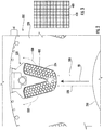
- the woven insulator 400 may be composed of a single electrically resistive material that is broken up into fibers or strips 410 and then woven together, as shown in FIG. 3 .
- the material of the woven insulator 400 may be polyamide/imide, aramid, glass, or similar material known to one of skill in the art.
- the woven composition of the woven insulator 400 allows the woven insulator 400 to be porous, which allows coolant 500 in a gaseous or liquid form to flow through the woven insulator 400. Once the coolant enters the rotating portion 222 by passing through the woven insulator 400, the coolant 500 may be in thermal communication with the generator field windings 224 of the rotating portion 222 and absorb heat from the generator field windings 224 of the rotating portion 222 prior to exiting the rotating portion 222 through the woven insulator 400.
- the woven insulator 400 may also be utilized in the exciter generator 240 as shown in FIG. 4 or anywhere within the electric generator 200 where extra cooling and electrical insulation is needed.
- a coolant 500 may be used to cool the exciter generator 240.
- the coolant 500 is a two-phase fluid capable of existing in a gaseous form and/or a liquid form.
- the coolant 500 may be an oil or any other coolant known to one of skill in the art. It is understood that while the exciter generator 240 is illustrated in FIG. 4 , the coolant 500 may be utilized similarly to cool other parts of the electric generator 200.
- the coolant 500 may be introduced into the exciter generator 240 from the shaft 210 to the rotating portion 242 of the exciter generator 240 and then may migrate in a radially outward direction R1 towards the stationary portion 246 of the electric generator 200. Due to elevated operating temperatures of the rotating portion 242 the coolant 500 may undergo a phase change and change from liquid form to gaseous form. The coolant 500 may have transformed into a gaseous form by the time the coolant 500 exits the rotating portion 242.
- friction is reduced between the stationary portion 246 and the rotating portion 242 by the coolant 500 being in a gaseous form rather than a liquid form in an area A2 between the stationary portion 246 and the rotating portion 242.
- a woven insulator 400 at least partially encloses the exciter field winding 244 of the rotating portion 242.
- the woven insulator 400 may fully enclose the exciter armature windings 244 of the rotating portion 242.
- the woven insulator 400 is configured to electrically insulate the exciter armature windings 244 from other components of the electric generator 200 while being permeably to coolant 500 in a gaseous or liquid form.
- the woven insulator 400 may be composed of a single electrically resistive material that is broken up into fibers or strips 410 and then woven together, as shown in FIG. 3 .
- the material of the woven insulator 400 may be polyamide/imide, aramid, glass, or similar material known to one of skill in the art.
- the woven composition of the woven insulator 400 allows the woven insulator 400 to be porous, which allows coolant 500 in a gaseous or liquid form to flow through the woven insulator 400. Once the coolant enters the rotating portion 242 by passing through the woven insulator 400, the coolant 500 may be in thermal communication with the exciter armature windings 244 of the rotating portion 242 and absorb heat from the exciter armature windings 244 of the rotating portion 242 prior to exiting the rotating portion 242 through the woven insulator 400.
Landscapes
- Engineering & Computer Science (AREA)
- Power Engineering (AREA)
- Physics & Mathematics (AREA)
- Spectroscopy & Molecular Physics (AREA)
- Insulation, Fastening Of Motor, Generator Windings (AREA)
- Motor Or Generator Cooling System (AREA)
Applications Claiming Priority (1)
| Application Number | Priority Date | Filing Date | Title |
|---|---|---|---|
| US16/363,104 US10998790B2 (en) | 2019-03-25 | 2019-03-25 | Fiber woven insulator for electric generator |
Publications (2)
| Publication Number | Publication Date |
|---|---|
| EP3716291A1 true EP3716291A1 (de) | 2020-09-30 |
| EP3716291B1 EP3716291B1 (de) | 2024-07-17 |
Family
ID=68621195
Family Applications (1)
| Application Number | Title | Priority Date | Filing Date |
|---|---|---|---|
| EP19210458.6A Active EP3716291B1 (de) | 2019-03-25 | 2019-11-20 | Fasergewebter isolator für einen elektrischen generator |
Country Status (2)
| Country | Link |
|---|---|
| US (1) | US10998790B2 (de) |
| EP (1) | EP3716291B1 (de) |
Families Citing this family (2)
| Publication number | Priority date | Publication date | Assignee | Title |
|---|---|---|---|---|
| DE102019113789A1 (de) * | 2019-05-23 | 2020-11-26 | Dr. Ing. H.C. F. Porsche Aktiengesellschaft | Stator einer elektrischen Maschine |
| EP4447269A1 (de) * | 2023-04-14 | 2024-10-16 | Wobben Properties GmbH | Spulenanordnung für eine elektrische maschine, stator, elektrische maschine und windenergieanlage |
Citations (3)
| Publication number | Priority date | Publication date | Assignee | Title |
|---|---|---|---|---|
| US20050218741A1 (en) * | 2004-03-18 | 2005-10-06 | Wnorowski Edward J Jr | Generators, transformers and stators containing high-strength, laminated, carbon-fiber windings |
| US20110273043A1 (en) * | 2010-05-05 | 2011-11-10 | Oeco, Llc | High reliability generator with dual drive path |
| US20180342919A1 (en) * | 2017-05-26 | 2018-11-29 | Ge Aviation Systems, Llc | Conductor and method of forming thereof |
Family Cites Families (9)
| Publication number | Priority date | Publication date | Assignee | Title |
|---|---|---|---|---|
| US2320866A (en) | 1941-07-29 | 1943-06-01 | Westinghouse Electric & Mfg Co | Flexible insulating material |
| US3749950A (en) | 1972-05-23 | 1973-07-31 | Gen Electric | Dynamoelectric machine having enhanced cooling |
| CH547028A (de) | 1972-06-16 | 1974-03-15 | Bbc Brown Boveri & Cie | Glimmschutzfolie, verfahren zu ihrer herstellung sowie ihre verwendung bei hochspannungswicklungen. |
| US4447947A (en) * | 1980-11-13 | 1984-05-15 | The United States Of America As Represented By The Secretary Of The Air Force | Process for making fluid-cooled electrical conductor |
| US4582749A (en) * | 1984-03-22 | 1986-04-15 | General Electric Company | Slot armor for dynamoelectric machines |
| US6242825B1 (en) * | 1998-11-25 | 2001-06-05 | Hitachi, Ltd. | Electric rotating machine with reduced thickness and volume of insulation |
| DE102011006680A1 (de) * | 2011-04-01 | 2012-10-04 | Aloys Wobben | Blechpaketanordnung |
| EP2645374A1 (de) * | 2012-03-26 | 2013-10-02 | Siemens Aktiengesellschaft | Zweilagiges Hochspannungsisolationssystem und elektrische Maschine |
| DE102012207535A1 (de) | 2012-05-07 | 2013-11-07 | Siemens Aktiengesellschaft | Isolierband-Material, Verfahren zur Herstellung und Verwendung dazu |
-
2019
- 2019-03-25 US US16/363,104 patent/US10998790B2/en active Active
- 2019-11-20 EP EP19210458.6A patent/EP3716291B1/de active Active
Patent Citations (3)
| Publication number | Priority date | Publication date | Assignee | Title |
|---|---|---|---|---|
| US20050218741A1 (en) * | 2004-03-18 | 2005-10-06 | Wnorowski Edward J Jr | Generators, transformers and stators containing high-strength, laminated, carbon-fiber windings |
| US20110273043A1 (en) * | 2010-05-05 | 2011-11-10 | Oeco, Llc | High reliability generator with dual drive path |
| US20180342919A1 (en) * | 2017-05-26 | 2018-11-29 | Ge Aviation Systems, Llc | Conductor and method of forming thereof |
Also Published As
| Publication number | Publication date |
|---|---|
| EP3716291B1 (de) | 2024-07-17 |
| US10998790B2 (en) | 2021-05-04 |
| US20200313489A1 (en) | 2020-10-01 |
Similar Documents
| Publication | Publication Date | Title |
|---|---|---|
| US3896320A (en) | High speed electric generator | |
| CN108604850B (zh) | 旋转电机 | |
| Klempner et al. | Handbook of large turbo-generator operation and maintenance | |
| US5347188A (en) | Electric machine with enhanced liquid cooling | |
| TW200822526A (en) | Dual-structured aircraft engine starter/generator | |
| US3663848A (en) | High-speed alternating current generators | |
| CN102985323B (zh) | 用于飞行器引擎的装置及相应的引擎和供应电力的方法 | |
| EP3422541B1 (de) | Selbsterregende synchrone reluktanzgeneratoren | |
| EP3716291B1 (de) | Fasergewebter isolator für einen elektrischen generator | |
| EP3116104A1 (de) | Steckplatzisolierung für elektrische maschinen | |
| CN110199450B (zh) | 能量存储系统以及能够稳定利用可变电力的系统 | |
| RU2384931C1 (ru) | Синхронная машина индукторного типа | |
| RU2579432C1 (ru) | Электромашина | |
| Kirtley et al. | MIT-EEI program on large superconducting machines | |
| US3330131A (en) | Refrigerator with transformer means | |
| CN111989848A (zh) | 同步电机 | |
| Nukki et al. | Exterior-rotor permanent magnet synchronous machine with toroidal windings for unmanned aerial vehicles | |
| CN108288879B (zh) | 用于电机的定子支承 | |
| RU2467451C2 (ru) | Коммутационная система электродвигателя постоянного тока | |
| EP4443713A1 (de) | Elektrische maschine mit einer leitungshalterungsanordnung | |
| King et al. | High speed water-cooled permanent magnet motor for pulse alternator-based pulse power systems | |
| GB2183102A (en) | Alternating current rotary convertors | |
| RU2656240C1 (ru) | Электродвижитель для получения свободной энергии, используя асинхронный генератор скольжения | |
| Varyukhin et al. | Design of an electric generator for an aircraft with a hybrid power system | |
| Huang et al. | A brushless DC motor design for an aircraft electro-hydraulic actuation system |
Legal Events
| Date | Code | Title | Description |
|---|---|---|---|
| PUAI | Public reference made under article 153(3) epc to a published international application that has entered the european phase |
Free format text: ORIGINAL CODE: 0009012 |
|
| STAA | Information on the status of an ep patent application or granted ep patent |
Free format text: STATUS: THE APPLICATION HAS BEEN PUBLISHED |
|
| AK | Designated contracting states |
Kind code of ref document: A1 Designated state(s): AL AT BE BG CH CY CZ DE DK EE ES FI FR GB GR HR HU IE IS IT LI LT LU LV MC MK MT NL NO PL PT RO RS SE SI SK SM TR |
|
| AX | Request for extension of the european patent |
Extension state: BA ME |
|
| STAA | Information on the status of an ep patent application or granted ep patent |
Free format text: STATUS: REQUEST FOR EXAMINATION WAS MADE |
|
| 17P | Request for examination filed |
Effective date: 20210326 |
|
| RBV | Designated contracting states (corrected) |
Designated state(s): AL AT BE BG CH CY CZ DE DK EE ES FI FR GB GR HR HU IE IS IT LI LT LU LV MC MK MT NL NO PL PT RO RS SE SI SK SM TR |
|
| STAA | Information on the status of an ep patent application or granted ep patent |
Free format text: STATUS: EXAMINATION IS IN PROGRESS |
|
| 17Q | First examination report despatched |
Effective date: 20230918 |
|
| REG | Reference to a national code |
Ref country code: DE Ref legal event code: R079 Free format text: PREVIOUS MAIN CLASS: H01B0003480000 Ipc: H02K0003240000 Ref country code: DE Ref legal event code: R079 Ref document number: 602019055291 Country of ref document: DE Free format text: PREVIOUS MAIN CLASS: H01B0003480000 Ipc: H02K0003240000 |
|
| GRAP | Despatch of communication of intention to grant a patent |
Free format text: ORIGINAL CODE: EPIDOSNIGR1 |
|
| STAA | Information on the status of an ep patent application or granted ep patent |
Free format text: STATUS: GRANT OF PATENT IS INTENDED |
|
| RIC1 | Information provided on ipc code assigned before grant |
Ipc: H02K 9/20 20060101ALI20240129BHEP Ipc: H02K 3/30 20060101ALI20240129BHEP Ipc: H01B 3/48 20060101ALI20240129BHEP Ipc: H02K 3/34 20060101ALI20240129BHEP Ipc: H02K 3/24 20060101AFI20240129BHEP |
|
| INTG | Intention to grant announced |
Effective date: 20240216 |
|
| GRAS | Grant fee paid |
Free format text: ORIGINAL CODE: EPIDOSNIGR3 |
|
| GRAA | (expected) grant |
Free format text: ORIGINAL CODE: 0009210 |
|
| STAA | Information on the status of an ep patent application or granted ep patent |
Free format text: STATUS: THE PATENT HAS BEEN GRANTED |
|
| AK | Designated contracting states |
Kind code of ref document: B1 Designated state(s): AL AT BE BG CH CY CZ DE DK EE ES FI FR GB GR HR HU IE IS IT LI LT LU LV MC MK MT NL NO PL PT RO RS SE SI SK SM TR |
|
| REG | Reference to a national code |
Ref country code: CH Ref legal event code: EP |
|
| REG | Reference to a national code |
Ref country code: DE Ref legal event code: R096 Ref document number: 602019055291 Country of ref document: DE |
|
| REG | Reference to a national code |
Ref country code: IE Ref legal event code: FG4D |
|
| REG | Reference to a national code |
Ref country code: LT Ref legal event code: MG9D |
|
| REG | Reference to a national code |
Ref country code: NL Ref legal event code: MP Effective date: 20240717 |
|
| PG25 | Lapsed in a contracting state [announced via postgrant information from national office to epo] |
Ref country code: PT Free format text: LAPSE BECAUSE OF FAILURE TO SUBMIT A TRANSLATION OF THE DESCRIPTION OR TO PAY THE FEE WITHIN THE PRESCRIBED TIME-LIMIT Effective date: 20241118 |
|
| REG | Reference to a national code |
Ref country code: AT Ref legal event code: MK05 Ref document number: 1705063 Country of ref document: AT Kind code of ref document: T Effective date: 20240717 |
|
| PG25 | Lapsed in a contracting state [announced via postgrant information from national office to epo] |
Ref country code: NL Free format text: LAPSE BECAUSE OF FAILURE TO SUBMIT A TRANSLATION OF THE DESCRIPTION OR TO PAY THE FEE WITHIN THE PRESCRIBED TIME-LIMIT Effective date: 20240717 |
|
| PG25 | Lapsed in a contracting state [announced via postgrant information from national office to epo] |
Ref country code: PT Free format text: LAPSE BECAUSE OF FAILURE TO SUBMIT A TRANSLATION OF THE DESCRIPTION OR TO PAY THE FEE WITHIN THE PRESCRIBED TIME-LIMIT Effective date: 20241118 Ref country code: NL Free format text: LAPSE BECAUSE OF FAILURE TO SUBMIT A TRANSLATION OF THE DESCRIPTION OR TO PAY THE FEE WITHIN THE PRESCRIBED TIME-LIMIT Effective date: 20240717 |
|
| PG25 | Lapsed in a contracting state [announced via postgrant information from national office to epo] |
Ref country code: NO Free format text: LAPSE BECAUSE OF FAILURE TO SUBMIT A TRANSLATION OF THE DESCRIPTION OR TO PAY THE FEE WITHIN THE PRESCRIBED TIME-LIMIT Effective date: 20241017 |
|
| PG25 | Lapsed in a contracting state [announced via postgrant information from national office to epo] |
Ref country code: GR Free format text: LAPSE BECAUSE OF FAILURE TO SUBMIT A TRANSLATION OF THE DESCRIPTION OR TO PAY THE FEE WITHIN THE PRESCRIBED TIME-LIMIT Effective date: 20241018 Ref country code: FI Free format text: LAPSE BECAUSE OF FAILURE TO SUBMIT A TRANSLATION OF THE DESCRIPTION OR TO PAY THE FEE WITHIN THE PRESCRIBED TIME-LIMIT Effective date: 20240717 Ref country code: PL Free format text: LAPSE BECAUSE OF FAILURE TO SUBMIT A TRANSLATION OF THE DESCRIPTION OR TO PAY THE FEE WITHIN THE PRESCRIBED TIME-LIMIT Effective date: 20240717 |
|
| PG25 | Lapsed in a contracting state [announced via postgrant information from national office to epo] |
Ref country code: BG Free format text: LAPSE BECAUSE OF FAILURE TO SUBMIT A TRANSLATION OF THE DESCRIPTION OR TO PAY THE FEE WITHIN THE PRESCRIBED TIME-LIMIT Effective date: 20240717 |
|
| PG25 | Lapsed in a contracting state [announced via postgrant information from national office to epo] |
Ref country code: LV Free format text: LAPSE BECAUSE OF FAILURE TO SUBMIT A TRANSLATION OF THE DESCRIPTION OR TO PAY THE FEE WITHIN THE PRESCRIBED TIME-LIMIT Effective date: 20240717 |
|
| PG25 | Lapsed in a contracting state [announced via postgrant information from national office to epo] |
Ref country code: AT Free format text: LAPSE BECAUSE OF FAILURE TO SUBMIT A TRANSLATION OF THE DESCRIPTION OR TO PAY THE FEE WITHIN THE PRESCRIBED TIME-LIMIT Effective date: 20240717 Ref country code: IS Free format text: LAPSE BECAUSE OF FAILURE TO SUBMIT A TRANSLATION OF THE DESCRIPTION OR TO PAY THE FEE WITHIN THE PRESCRIBED TIME-LIMIT Effective date: 20241117 |
|
| PG25 | Lapsed in a contracting state [announced via postgrant information from national office to epo] |
Ref country code: HR Free format text: LAPSE BECAUSE OF FAILURE TO SUBMIT A TRANSLATION OF THE DESCRIPTION OR TO PAY THE FEE WITHIN THE PRESCRIBED TIME-LIMIT Effective date: 20240717 |
|
| PG25 | Lapsed in a contracting state [announced via postgrant information from national office to epo] |
Ref country code: RS Free format text: LAPSE BECAUSE OF FAILURE TO SUBMIT A TRANSLATION OF THE DESCRIPTION OR TO PAY THE FEE WITHIN THE PRESCRIBED TIME-LIMIT Effective date: 20241017 Ref country code: ES Free format text: LAPSE BECAUSE OF FAILURE TO SUBMIT A TRANSLATION OF THE DESCRIPTION OR TO PAY THE FEE WITHIN THE PRESCRIBED TIME-LIMIT Effective date: 20240717 |
|
| PG25 | Lapsed in a contracting state [announced via postgrant information from national office to epo] |
Ref country code: RS Free format text: LAPSE BECAUSE OF FAILURE TO SUBMIT A TRANSLATION OF THE DESCRIPTION OR TO PAY THE FEE WITHIN THE PRESCRIBED TIME-LIMIT Effective date: 20241017 Ref country code: PL Free format text: LAPSE BECAUSE OF FAILURE TO SUBMIT A TRANSLATION OF THE DESCRIPTION OR TO PAY THE FEE WITHIN THE PRESCRIBED TIME-LIMIT Effective date: 20240717 Ref country code: NO Free format text: LAPSE BECAUSE OF FAILURE TO SUBMIT A TRANSLATION OF THE DESCRIPTION OR TO PAY THE FEE WITHIN THE PRESCRIBED TIME-LIMIT Effective date: 20241017 Ref country code: LV Free format text: LAPSE BECAUSE OF FAILURE TO SUBMIT A TRANSLATION OF THE DESCRIPTION OR TO PAY THE FEE WITHIN THE PRESCRIBED TIME-LIMIT Effective date: 20240717 Ref country code: IS Free format text: LAPSE BECAUSE OF FAILURE TO SUBMIT A TRANSLATION OF THE DESCRIPTION OR TO PAY THE FEE WITHIN THE PRESCRIBED TIME-LIMIT Effective date: 20241117 Ref country code: HR Free format text: LAPSE BECAUSE OF FAILURE TO SUBMIT A TRANSLATION OF THE DESCRIPTION OR TO PAY THE FEE WITHIN THE PRESCRIBED TIME-LIMIT Effective date: 20240717 Ref country code: GR Free format text: LAPSE BECAUSE OF FAILURE TO SUBMIT A TRANSLATION OF THE DESCRIPTION OR TO PAY THE FEE WITHIN THE PRESCRIBED TIME-LIMIT Effective date: 20241018 Ref country code: FI Free format text: LAPSE BECAUSE OF FAILURE TO SUBMIT A TRANSLATION OF THE DESCRIPTION OR TO PAY THE FEE WITHIN THE PRESCRIBED TIME-LIMIT Effective date: 20240717 Ref country code: ES Free format text: LAPSE BECAUSE OF FAILURE TO SUBMIT A TRANSLATION OF THE DESCRIPTION OR TO PAY THE FEE WITHIN THE PRESCRIBED TIME-LIMIT Effective date: 20240717 Ref country code: BG Free format text: LAPSE BECAUSE OF FAILURE TO SUBMIT A TRANSLATION OF THE DESCRIPTION OR TO PAY THE FEE WITHIN THE PRESCRIBED TIME-LIMIT Effective date: 20240717 Ref country code: AT Free format text: LAPSE BECAUSE OF FAILURE TO SUBMIT A TRANSLATION OF THE DESCRIPTION OR TO PAY THE FEE WITHIN THE PRESCRIBED TIME-LIMIT Effective date: 20240717 |
|
| PG25 | Lapsed in a contracting state [announced via postgrant information from national office to epo] |
Ref country code: SM Free format text: LAPSE BECAUSE OF FAILURE TO SUBMIT A TRANSLATION OF THE DESCRIPTION OR TO PAY THE FEE WITHIN THE PRESCRIBED TIME-LIMIT Effective date: 20240717 Ref country code: RO Free format text: LAPSE BECAUSE OF FAILURE TO SUBMIT A TRANSLATION OF THE DESCRIPTION OR TO PAY THE FEE WITHIN THE PRESCRIBED TIME-LIMIT Effective date: 20240717 Ref country code: DK Free format text: LAPSE BECAUSE OF FAILURE TO SUBMIT A TRANSLATION OF THE DESCRIPTION OR TO PAY THE FEE WITHIN THE PRESCRIBED TIME-LIMIT Effective date: 20240717 |
|
| REG | Reference to a national code |
Ref country code: DE Ref legal event code: R097 Ref document number: 602019055291 Country of ref document: DE |
|
| PG25 | Lapsed in a contracting state [announced via postgrant information from national office to epo] |
Ref country code: EE Free format text: LAPSE BECAUSE OF FAILURE TO SUBMIT A TRANSLATION OF THE DESCRIPTION OR TO PAY THE FEE WITHIN THE PRESCRIBED TIME-LIMIT Effective date: 20240717 |
|
| PG25 | Lapsed in a contracting state [announced via postgrant information from national office to epo] |
Ref country code: CZ Free format text: LAPSE BECAUSE OF FAILURE TO SUBMIT A TRANSLATION OF THE DESCRIPTION OR TO PAY THE FEE WITHIN THE PRESCRIBED TIME-LIMIT Effective date: 20240717 |
|
| PG25 | Lapsed in a contracting state [announced via postgrant information from national office to epo] |
Ref country code: SK Free format text: LAPSE BECAUSE OF FAILURE TO SUBMIT A TRANSLATION OF THE DESCRIPTION OR TO PAY THE FEE WITHIN THE PRESCRIBED TIME-LIMIT Effective date: 20240717 |
|
| PLBE | No opposition filed within time limit |
Free format text: ORIGINAL CODE: 0009261 |
|
| STAA | Information on the status of an ep patent application or granted ep patent |
Free format text: STATUS: NO OPPOSITION FILED WITHIN TIME LIMIT |
|
| 26N | No opposition filed |
Effective date: 20250422 |
|
| REG | Reference to a national code |
Ref country code: CH Ref legal event code: PL |
|
| PG25 | Lapsed in a contracting state [announced via postgrant information from national office to epo] |
Ref country code: MC Free format text: LAPSE BECAUSE OF FAILURE TO SUBMIT A TRANSLATION OF THE DESCRIPTION OR TO PAY THE FEE WITHIN THE PRESCRIBED TIME-LIMIT Effective date: 20240717 |
|
| PG25 | Lapsed in a contracting state [announced via postgrant information from national office to epo] |
Ref country code: LU Free format text: LAPSE BECAUSE OF NON-PAYMENT OF DUE FEES Effective date: 20241120 |
|
| REG | Reference to a national code |
Ref country code: CH Ref legal event code: PL |
|
| PG25 | Lapsed in a contracting state [announced via postgrant information from national office to epo] |
Ref country code: CH Free format text: LAPSE BECAUSE OF NON-PAYMENT OF DUE FEES Effective date: 20241130 |
|
| REG | Reference to a national code |
Ref country code: BE Ref legal event code: MM Effective date: 20241130 |
|
| PG25 | Lapsed in a contracting state [announced via postgrant information from national office to epo] |
Ref country code: SE Free format text: LAPSE BECAUSE OF FAILURE TO SUBMIT A TRANSLATION OF THE DESCRIPTION OR TO PAY THE FEE WITHIN THE PRESCRIBED TIME-LIMIT Effective date: 20240717 |
|
| PG25 | Lapsed in a contracting state [announced via postgrant information from national office to epo] |
Ref country code: BE Free format text: LAPSE BECAUSE OF NON-PAYMENT OF DUE FEES Effective date: 20241130 |
|
| PG25 | Lapsed in a contracting state [announced via postgrant information from national office to epo] |
Ref country code: IE Free format text: LAPSE BECAUSE OF NON-PAYMENT OF DUE FEES Effective date: 20241120 |
|
| PGFP | Annual fee paid to national office [announced via postgrant information from national office to epo] |
Ref country code: DE Payment date: 20251022 Year of fee payment: 7 |
|
| PGFP | Annual fee paid to national office [announced via postgrant information from national office to epo] |
Ref country code: GB Payment date: 20251023 Year of fee payment: 7 |
|
| PGFP | Annual fee paid to national office [announced via postgrant information from national office to epo] |
Ref country code: FR Payment date: 20251023 Year of fee payment: 7 |
|
| PG25 | Lapsed in a contracting state [announced via postgrant information from national office to epo] |
Ref country code: IT Free format text: LAPSE BECAUSE OF FAILURE TO SUBMIT A TRANSLATION OF THE DESCRIPTION OR TO PAY THE FEE WITHIN THE PRESCRIBED TIME-LIMIT Effective date: 20240717 |
|
| PG25 | Lapsed in a contracting state [announced via postgrant information from national office to epo] |
Ref country code: HU Free format text: LAPSE BECAUSE OF FAILURE TO SUBMIT A TRANSLATION OF THE DESCRIPTION OR TO PAY THE FEE WITHIN THE PRESCRIBED TIME-LIMIT; INVALID AB INITIO Effective date: 20191120 |
|
| PG25 | Lapsed in a contracting state [announced via postgrant information from national office to epo] |
Ref country code: CY Free format text: LAPSE BECAUSE OF FAILURE TO SUBMIT A TRANSLATION OF THE DESCRIPTION OR TO PAY THE FEE WITHIN THE PRESCRIBED TIME-LIMIT; INVALID AB INITIO Effective date: 20191120 |