EP3716229A1 - System and method of reducing a communication range - Google Patents
System and method of reducing a communication range Download PDFInfo
- Publication number
- EP3716229A1 EP3716229A1 EP20157054.6A EP20157054A EP3716229A1 EP 3716229 A1 EP3716229 A1 EP 3716229A1 EP 20157054 A EP20157054 A EP 20157054A EP 3716229 A1 EP3716229 A1 EP 3716229A1
- Authority
- EP
- European Patent Office
- Prior art keywords
- signals
- transceiver
- range
- controller circuit
- transmission
- Prior art date
- Legal status (The legal status is an assumption and is not a legal conclusion. Google has not performed a legal analysis and makes no representation as to the accuracy of the status listed.)
- Granted
Links
Images


Classifications
-
- H—ELECTRICITY
- H04—ELECTRIC COMMUNICATION TECHNIQUE
- H04B—TRANSMISSION
- H04B1/00—Details of transmission systems, not covered by a single one of groups H04B3/00 - H04B13/00; Details of transmission systems not characterised by the medium used for transmission
- H04B1/38—Transceivers, i.e. devices in which transmitter and receiver form a structural unit and in which at least one part is used for functions of transmitting and receiving
- H04B1/3822—Transceivers, i.e. devices in which transmitter and receiver form a structural unit and in which at least one part is used for functions of transmitting and receiving specially adapted for use in vehicles
-
- H—ELECTRICITY
- H04—ELECTRIC COMMUNICATION TECHNIQUE
- H04W—WIRELESS COMMUNICATION NETWORKS
- H04W4/00—Services specially adapted for wireless communication networks; Facilities therefor
- H04W4/02—Services making use of location information
- H04W4/021—Services related to particular areas, e.g. point of interest [POI] services, venue services or geofences
- H04W4/022—Services related to particular areas, e.g. point of interest [POI] services, venue services or geofences with dynamic range variability
-
- G—PHYSICS
- G07—CHECKING-DEVICES
- G07C—TIME OR ATTENDANCE REGISTERS; REGISTERING OR INDICATING THE WORKING OF MACHINES; GENERATING RANDOM NUMBERS; VOTING OR LOTTERY APPARATUS; ARRANGEMENTS, SYSTEMS OR APPARATUS FOR CHECKING NOT PROVIDED FOR ELSEWHERE
- G07C9/00—Individual registration on entry or exit
- G07C9/00174—Electronically operated locks; Circuits therefor; Nonmechanical keys therefor, e.g. passive or active electrical keys or other data carriers without mechanical keys
- G07C9/00309—Electronically operated locks; Circuits therefor; Nonmechanical keys therefor, e.g. passive or active electrical keys or other data carriers without mechanical keys operated with bidirectional data transmission between data carrier and locks
-
- H—ELECTRICITY
- H04—ELECTRIC COMMUNICATION TECHNIQUE
- H04W—WIRELESS COMMUNICATION NETWORKS
- H04W4/00—Services specially adapted for wireless communication networks; Facilities therefor
- H04W4/80—Services using short range communication, e.g. near-field communication [NFC], radio-frequency identification [RFID] or low energy communication
-
- H—ELECTRICITY
- H04—ELECTRIC COMMUNICATION TECHNIQUE
- H04W—WIRELESS COMMUNICATION NETWORKS
- H04W52/00—Power management, e.g. Transmission Power Control [TPC] or power classes
- H04W52/04—Transmission power control [TPC]
- H04W52/18—TPC being performed according to specific parameters
- H04W52/24—TPC being performed according to specific parameters using SIR [Signal to Interference Ratio] or other wireless path parameters
-
- G—PHYSICS
- G07—CHECKING-DEVICES
- G07C—TIME OR ATTENDANCE REGISTERS; REGISTERING OR INDICATING THE WORKING OF MACHINES; GENERATING RANDOM NUMBERS; VOTING OR LOTTERY APPARATUS; ARRANGEMENTS, SYSTEMS OR APPARATUS FOR CHECKING NOT PROVIDED FOR ELSEWHERE
- G07C9/00—Individual registration on entry or exit
- G07C9/00174—Electronically operated locks; Circuits therefor; Nonmechanical keys therefor, e.g. passive or active electrical keys or other data carriers without mechanical keys
- G07C9/00309—Electronically operated locks; Circuits therefor; Nonmechanical keys therefor, e.g. passive or active electrical keys or other data carriers without mechanical keys operated with bidirectional data transmission between data carrier and locks
- G07C2009/00341—Electronically operated locks; Circuits therefor; Nonmechanical keys therefor, e.g. passive or active electrical keys or other data carriers without mechanical keys operated with bidirectional data transmission between data carrier and locks keyless data carrier having more than one limited data transmission ranges
- G07C2009/00357—Electronically operated locks; Circuits therefor; Nonmechanical keys therefor, e.g. passive or active electrical keys or other data carriers without mechanical keys operated with bidirectional data transmission between data carrier and locks keyless data carrier having more than one limited data transmission ranges and the lock having more than one limited data transmission ranges
-
- G—PHYSICS
- G07—CHECKING-DEVICES
- G07C—TIME OR ATTENDANCE REGISTERS; REGISTERING OR INDICATING THE WORKING OF MACHINES; GENERATING RANDOM NUMBERS; VOTING OR LOTTERY APPARATUS; ARRANGEMENTS, SYSTEMS OR APPARATUS FOR CHECKING NOT PROVIDED FOR ELSEWHERE
- G07C2209/00—Indexing scheme relating to groups G07C9/00 - G07C9/38
- G07C2209/60—Indexing scheme relating to groups G07C9/00174 - G07C9/00944
- G07C2209/63—Comprising locating means for detecting the position of the data carrier, i.e. within the vehicle or within a certain distance from the vehicle
-
- H—ELECTRICITY
- H04—ELECTRIC COMMUNICATION TECHNIQUE
- H04W—WIRELESS COMMUNICATION NETWORKS
- H04W88/00—Devices specially adapted for wireless communication networks, e.g. terminals, base stations or access point devices
- H04W88/02—Terminal devices
Definitions
- This disclosure generally relates to a system that reduces a communication range between wireless communication devices.
- Bluetooth Low Energy when used for keyless vehicle entry applications, may present challenges for distinguishing 'fob'-to-vehicle distances.
- Existing BLE industry directions for new angle-of-arrival (AoA) and time-of-flight (ToF) features may result in increased costs and complexity.
- the present invention proposes to solve the above mentioned problem by providing a system comprising a first transceiver configured to transmit first radio frequency (RF) signals.
- the first transceiver is further configured to output the first RF signals at a first transmission level corresponding to a first transmission range.
- a controller circuit is communicatively coupled with the first transceiver.
- the controller circuit is configured to attenuate the first RF signals to transfer the first RF signals at a second transmission level lower than the first transmission level.
- the second transmission level corresponds to a shorter transmission range than the first transmission range.
- the controller circuit detects a presence of at least one second transceiver within the shorter transmission range using the first RF signals transmitted at the second transmission level.
- the present invention also proposes a method, comprising the steps of:
- the method further comprises the step of:
- the method further comprises:
- the method further includes the step of determining, with the controller circuit, a state of connection between the first transceiver and the at least one second transceiver; the state of connection including a connected state and unconnected state.
- the method further comprises:
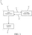
- Fig. 1 illustrates an example of a system 10 that reduces a communication range between wireless communication devices.
- the system 10 may provide various improvements over other systems.
- the system 10 includes a first transceiver 12 configured to transmit first radio frequency (RF) signals 14.
- the first RF signals 14 are high frequency RF signals that comply with a BLUETOOTH® Core Specification version 4.2 and later, including BLUETOOTH® Low Energy (hereafter BLE).
- the first transceiver 12 is a BLUETOOTH® device that is installed in a vehicle as part of a telematic control unit (TCU).
- the TCU controls tracking of the vehicle's position and includes, a global positioning system unit (GPS), an external mobile communication interface to communicate the position to a database server, an electronic processing unit, a microcontroller and/or a microprocessor, a memory or electronic storage media, and interface communications buses to other vehicle systems.
- GPS global positioning system unit
- the TCU controls tracking of the vehicle's position and includes, a global positioning system unit (GPS), an external mobile communication interface to communicate the position to a database server, an electronic processing unit, a microcontroller and/or a microprocessor, a memory or electronic storage media, and interface communications buses to other vehicle systems.
- GPS global positioning system unit
- the first transceiver 12 is configured to both transmit and receive BLE RF signals.
- the first transceiver 12 includes an antenna (not shown) configured to emit and collect the BLE RF signals.
- the antenna is a micro-strip antenna.
- the antenna is a metal plate antenna.
- the antenna is a chip antenna.
- the BLE RF signals are transmitted in a 2.4 GHz frequency band (i.e., 2.400 - 2.4835 GHz) and have a maximum theoretical unobstructed range exceeding 600 meters (600m).
- BLE is commonly employed in mobile phones, gaming systems, headsets, automotive infotainment systems, and personal computers.
- BLE devices are detected through a procedure based on broadcasting advertising packets from a host device (e.g.
- the vehicle receives scan request packets from a remote device (e.g., a smartphone). This is done using three separate frequencies within the frequency band, in order to reduce interference.
- the BLE advertising device sends a packet of information on at least one of the three frequencies, with a repetition period called the advertising interval.
- a BLE scanner in the host device listens to the frequency for a duration called the scan window, when the scan request packets are received, which is periodically repeated every scan interval.
- BLE devices may be paired by sharing a code unique to each BLE device, called a link key. The link keys are exchanged between the pairing devices and stored in the pairing devices to establish a secure connection, also referred to as a bond.
- the unconnected and/or unpaired devices may share a limited amount of information without pairing, such as a device name, a device class, a list of services provided by the device and other technical information specific to the device (e.g., device services, manufacturer, BLE specification, and clock offset).
- the first transceiver 12 is further configured to output the first RF signals 14 at a first transmission level corresponding to a first transmission range.
- the first transmission level is a full power level of the first transceiver 12 (e.g., 0.5mW to 10mW) that corresponds to a maximum range of transmission (e.g., greater than 600m).
- the system 10 also includes a controller circuit 16 communicatively coupled with the first transceiver 12.
- the controller circuit 16 may include a processor (not shown) such as a microprocessor or other control circuitry such as analog and/or digital control circuitry.
- the control circuitry may include one or more application-specific integrated circuits (ASICs) or field programmable gate arrays (FPGAs) that are persistently programmed to perform the techniques, or may include one or more general purpose hardware processors programmed to perform the techniques pursuant to program instructions in firmware, memory, other storage, or a combination.
- the controller circuit 16 may also combine custom hard-wired logic, ASICs, or FPGAs with custom programming to accomplish the techniques.
- the controller circuit 16 may include a memory or storage media (not shown), including non-volatile memory, such as electrically erasable programmable read-only memory (EEPROM) for storing one or more routines, thresholds, and captured data.
- EEPROM electrically erasable programmable read-only memory
- the controller circuit 16 stores data and allows individual bytes to be erased and reprogrammed by applying special programming signals.
- the controller circuit 16 may include other examples of non-volatile memory, such as flash memory, read-only memory (ROM), programmable read-only memory (PROM), and erasable programmable read-only memory (EPROM).
- the controller circuit 16 may include volatile memory, such as dynamic random-access memory (DRAM), static random-access memory (SRAM).
- DRAM dynamic random-access memory
- SRAM static random-access memory
- the one or more routines may be executed by the processor to perform steps for detecting a presence of at least one second transceiver 18 based on signals received by the controller circuit 16 from the first transceiver 12 as described herein.
- the first transceiver 12 includes the controller circuit 16 (i.e., the controller circuit 16 is integral to the first transceiver 12 electrical packaging).
- the first transceiver 12 and the controller circuit 16 are separate devices.
- the controller circuit 16 is configured to attenuate (i.e., weaken, diminish, reduce, etc.) the first RF signals 14 to transfer the first RF signals 14 at a second transmission level that is lower than the first transmission level.
- Signal attenuation reduces a strength or power of the RF signal without appreciably distorting the RF signal's waveform. That is, the power is reduced without significantly affecting the wavelength and/or modulation characteristics of the RF signal. Distorting the waveform would negatively affect the efficiency of the first transceiver 12.
- Signal attenuation typically is expressed in units of decibels (dB), where a 10 dB reduction represents a 10 fold reduction in the signal power.
- the decibel is a logarithmic-based value that is used to express the ratio of one value of a power to another power value (i.e. a power ratio) on a logarithmic scale.
- a 1 dB reduction in the signal power corresponds to an approximate 21% reduction in power
- a 3 dB reduction in the signal power corresponds to an approximate 50% reduction in power.
- the second transmission level corresponds to a shorter transmission range than the first transmission range due to the reduced signal power.
- the power of an RF signal is expressed in units of dBm, which indicates the power ratio is referenced to one milliwatt (1mW).
- a power level of 0.0dBm corresponds to a power of 1mW.
- the controller circuit 16 attenuates the first RF signals 14 up to about 50dBm out of a total BLE RF link budget of 90dBm to 105dBm.
- the link budget is a difference between the maximum RF signal power (about +5dBm to +10dBm) and the best reception sensitivity (about -90dBm to - 95dBm).
- attenuating first RF signals 14 by 50dBm eliminates almost half of the original dBm link budget.
- the 50dBm power reduction is approximately equivalent to reducing a radius of coverage to about 0.316% of the original radius of coverage.
- the controller circuit 16 reduces the communication range between the system 10 and the second transceiver 18 to a range of about 0.4m to about 2m, from the initial range of 600m.
- Fig. 2 is a table that indicates estimates of the reduction in the communication distance at various levels of attenuation, for both ideal (i.e., no signal interference), and typical environmental conditions that include common levels of RF signal interference and RF signal noise.
- the controller circuit 16 attenuates the first RF signals 14 through a separate signal attenuator 22 device that is communicatively coupled to a switched port interface 24.
- the switched port interface 24 has at least one RF antenna (not shown) communicatively coupled to at least two switched ports.
- the controller circuit 16 routes the first RF signals 14 from the first transceiver 12 to a first switched port, whereby the first RF signals 14 pass through the signal attenuator 22 interposed between the first switched port and the first transceiver 12, thereby reducing a range of communication of the first RF signals 14.
- the signal attenuator 22 may be any signal attenuator 22 compatible with the BLE specification.
- the signal attenuator 22 attenuates the first RF signals 14 at a fixed rate (e.g., 50dBm). In another example, the signal attenuator 22 attenuates the first RF signals 14 at a variable rate (e.g., 10dBm-50dBm).
- the controller circuit 16 attenuates the first RF signals 14 by reducing a transmission power of the first transceiver 12 without using the separate signal attenuator 22 device.
- the controller circuit 16 sends deep-level configuration commands, such as transmit packet-power commands and/or power table commands to the first transceiver 12 to reduce the transmitted power of the first RF signals 14 to the desired power that corresponds to the desired communication range.
- the controller circuit 16 detects the presence of the at least one second transceiver 18 within the shorter transmission range (e.g., about 0.4m to about 2m) using the first RF signals 14 transmitted at the second transmission level. That is, the first transceiver 12 communicates with the at least one second transceiver 18 within the shorter transmission range enabling the detection by the controller circuit 16.
- This reduced communication range has the technical advantage of enabling applications such as a "smartphone as a vehicle key", where large communication distances between the smartphone and the vehicle may be problematic for vehicle security.
- the system 10 may "ignore" potential interfering or malicious BLE signals from distant BLE devices during critical vehicle security modes, such as remote locking and unlocking, and/or remote starting.
- the second transceiver 18 is a key fob. In another example, the second transceiver 18 is a tablet. In another example, the second transceiver 18 is a smartwatch. In the example illustrated in Fig. 1 , the second transceiver 18 is a smartphone configured to transmit second RF signals 20 in accordance with the BLE specification, and is paired with the system 10 according to the BLE specification as described above.
- the first transceiver 12 also receives the second RF signals 20 transmitted from the at least one second transceiver 18.
- the second RF signals 20 have a first reception level corresponding to a first reception range in accordance with the maximum theoretical BLE range described above (i.e. 600m).
- the controller circuit 16 attenuates the received second RF signals 20 to transfer the second RF signals 20 at a second reception level.
- the second reception level corresponds to a second reception range that corresponds to a shorter reception range than the first reception range. This shorter reception range limits the communication range of the at least one second transceiver 18 with respect to the first transceiver 12.
- the controller circuit 16 attenuates the second RF signals 20 up to about 50dBm, reducing the communication range between the system 10 and the second transceiver 18 to the range of about 0.4m to about 2m, from the initial range of 600m. It will be appreciated that the controller circuit 16 may attenuate the first RF signals 14 and the second RF signals 20 at the same, or different, levels of attenuation.
- the controller circuit 16 attenuates the second RF signals 20 through the separate signal attenuator 22 device that is communicatively coupled to the switched port interface 24.
- the controller circuit 16 routes the second RF signals 20 from the second transceiver 18 to the first switched port, whereby the second RF signals 20 pass through the signal attenuator 22 interposed between the first switched port and the first transceiver 12, thereby reducing the range of communication of the RF signals.
- the signal attenuator 22 is bidirectional and attenuates RF signals in both directions (i.e. transmitted and received).
- the controller circuit 16 attenuates the second RF signals 20 by reducing a reception power of the first transceiver 12 without using the separate signal attenuator 22 device.
- the controller circuit 16 sends deep-level configuration commands, such as receive automatic gain control (AGC) attenuator selections to the first transceiver 12 to attenuate the second RF signals 20.
- AGC automatic gain control
- the controller circuit 16 further determines a state of connection between the first transceiver 12 and the at least one second transceiver 18.
- the state of connection includes a connected state and unconnected state. In the unconnected state, the first transceiver 12 and the at least one second transceiver 18 are able to communicate a limited amount of information without being paired, as described above.
- the first RF signals 14 include the advertising packets and the second RF signals 20 include the scan request packets.
- the controller circuit 16 attenuates the first RF signals 14 and/or the second RF signals 20 when the first transceiver 12 and the at least one second transceiver 18 are in the unconnected state.
- the controller circuit 16 ceases to attenuate the first RF signals 14 and the second RF signals 20 to enable the transfer of information at up to the maximum power levels of the system 10.
- the controller circuit 16 may use other criteria besides the state of connection to determine whether to attenuate the first RF signals 14 and/or the second RF signals 20. In an example, the controller circuit 16 attenuates the first RF signals 14 and/or the second RF signals 20 when the vehicle doors are locked, and ceases to attenuate the RF signals when the vehicle is unlocked. In another example, the controller circuit 16 attenuates the first RF signals 14 and/or the second RF signals 20 when the vehicle is turned off (e.g., key off), and ceases to attenuate the RF signals when the vehicle is turned on.
- the controller circuit 16 may use other criteria besides the state of connection to determine whether to attenuate the first RF signals 14 and/or the second RF signals 20. In an example, the controller circuit 16 attenuates the first RF signals 14 and/or the second RF signals 20 when the vehicle doors are locked, and ceases to attenuate the RF signals when the vehicle is unlocked. In another example, the controller circuit 16 at
- the controller circuit 16 attenuates the first RF signals 14 and/or the second RF signals 20 when the TCU has been commanded into a "reduced range” mode via another TCU interface, such as a managed cellular-network signal, and ceases to attenuate the RF signals when the TCU has been commanded into a "normal range” mode.
- the controller circuit 16 attenuates the first RF signals 14 and/or the second RF signals 20 when the TCU has counted down a preset timing interval, but does not attenuate the RF signals when the TCU is still counting down the preset timing interval. It will be appreciated that any combination of methods listed above may be implemented for optimal security and user convenience features.
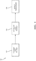
- Fig. 4 is a flow chart illustrating an example of a method 100 to reduce a communication distance.
- Step 102 TRANSMIT FIRST SIGNALS, includes transmitting the first RF signals 14 with a first transceiver 12 as described above.
- the first RF signals 14 have the first transmission range that corresponds to the maximum range of transmission of the first transceiver 12 (e.g., greater than 600m).
- Step 104 ATTENUATE FIRST SIGNALS, includes attenuating the first RF signals 14 with the controller circuit 16 communicatively coupled to the first transceiver 12 as described above.
- the controller circuit 16 reduces the strength of the first RF signals 14 from the first transmission level to the second transmission level, corresponding to the shorter transmission range.
- the controller circuit 16 routes the first RF signal through the separate signal attenuator 22.
- the controller circuit 16 attenuates the first RF signals 14 without using the separate signal attenuator 22 device by sending deep-level configuration commands such as transmit packet-power commands or power table commands to the first transceiver 12.
- Step 106 DETECT TRANSCEIVER, includes detecting, with the controller circuit 16, the at least one second transceiver 18 using the first RF signals 14 transmitted at the second transmission level.
- the controller circuit 16 detects the presence of the at least one second transceiver 18 within the shorter transmission range as described above.
- the first transceiver 12 receives second RF signals 20 transmitted from the at least one second transceiver 18 as described above.
- the controller circuit 16 attenuates the second RF signals 20 from the first reception level to the second reception level, corresponding to the shorter reception range than the first reception range.
- the shorter reception range limits the communication range of the at least one second transceiver 18 with respect to the first transceiver 12.
- the first transceiver 12 and the at least one second transceiver 18 transmit and receive the first RF signals 14 and the second RF signals 20 in accordance with the BLUETOOTH® Core Specification version 4.2 and later, as described above.
- the first RF signals 14 include advertising packets and the second RF signals 20 include scan request packets.
- the controller circuit 16 attenuates the first RF signals 14 and/or the second RF signals 20 when the first transceiver 12 and the second transceiver 18 are in the unconnected state, as described above.
- the controller circuit 16 ceases to attenuate the first RF signals 14 and/or the second RF signals 20 when the first transceiver 12 and the second transceiver 18 are in the connected state, as described above.
- a system 10 for reducing a communication range, and a method 100 of reducing the communication range are provided.
- the system 10 is an improvement over other systems because the system 10 ignores RF signals from distant devices that may pose a security threat.
- first contact could be termed a second contact
- second contact could be termed a first contact
- the first contact and the second contact are both contacts, but they are not the same contact.
- the terminology used in the description of the various described embodiments herein is for the purpose of describing particular embodiments only and is not intended to be limiting. As used in the description of the various described embodiments and the appended claims, the singular forms "a”, “an” and “the” are intended to include the plural forms as well, unless the context clearly indicates otherwise. It will also be understood that the term “and/or” as used herein refers to and encompasses any and all possible combinations of one or more of the associated listed items.
- the phrase “if it is determined” or “if [a stated condition or event] is detected” is, optionally, construed to mean “upon determining” or “in response to determining” or “upon detecting [the stated condition or event]” or “in response to detecting [the stated condition or event],” depending on the context.
Landscapes
- Engineering & Computer Science (AREA)
- Computer Networks & Wireless Communication (AREA)
- Signal Processing (AREA)
- Physics & Mathematics (AREA)
- General Physics & Mathematics (AREA)
- Mobile Radio Communication Systems (AREA)
- Transceivers (AREA)
- Lock And Its Accessories (AREA)
Abstract
Description
- This application claims the benefit of
U.S. Patent Application No. 16/370,064, filed March 29, 2019 - This disclosure generally relates to a system that reduces a communication range between wireless communication devices.
- Bluetooth Low Energy (BLE), when used for keyless vehicle entry applications, may present challenges for distinguishing 'fob'-to-vehicle distances. Existing BLE industry directions for new angle-of-arrival (AoA) and time-of-flight (ToF) features may result in increased costs and complexity.
- The present invention proposes to solve the above mentioned problem by providing a system comprising a first transceiver configured to transmit first radio frequency (RF) signals. The first transceiver is further configured to output the first RF signals at a first transmission level corresponding to a first transmission range. A controller circuit is communicatively coupled with the first transceiver. The controller circuit is configured to attenuate the first RF signals to transfer the first RF signals at a second transmission level lower than the first transmission level. The second transmission level corresponds to a shorter transmission range than the first transmission range. The controller circuit detects a presence of at least one second transceiver within the shorter transmission range using the first RF signals transmitted at the second transmission level.
- According to other advantageous features of the present invention:
- the first transceiver receives second RF signals transmitted from at least one second transceiver; the second RF signals having a first reception level corresponding to a first reception range; wherein the controller circuit attenuates the second RF signals to transfer the second RF signals at a second reception level; the second reception level corresponding to a second reception range corresponding to a shorter reception range than the first reception range; thereby limiting a communication range of the at least one second transceiver with respect to the first transceiver;
- the at least one second transceiver is one of a smartphone, a tablet, a key fob, and a smartwatch;
- the first transceiver transmits and receives the first RF signals in accordance with a BLUETOOTH® Core Specification version 4.2 and later;
- the first RF signals include advertising packets;
- the controller circuit further determines a state of connection between the first transceiver and the at least one second transceiver; the state of connection including a connected state and unconnected state;
- the controller circuit attenuates the first RF signals when the first transceiver and the at least one second transceiver are in the unconnected state;
- the controller circuit attenuates the second RF signals when the first transceiver and the at least one second transceiver are in the unconnected state;
- the at least one second transceiver transmits and receives the second RF signals in accordance with a BLUETOOTH® Core Specification version 4.2 and later;
- the second RF signals include scan request packets;
- the controller circuit attenuates the first RF signals up to 50dBm;
- the controller circuit reduces the communication range to a range of about 0.4m to about 2m;
- the controller circuit attenuates the second RF signals up to 50dBm;
- the controller circuit reduces the communication range to a range of about 0.4m to about 2m;
- The present invention also proposes a method, comprising the steps of:
- transmitting first radio frequency (RF) signals with a first transceiver, the first transceiver is configured to output the first RF signals at a first transmission level corresponding to a first transmission range.
- attenuating the first RF signals, with a controller circuit communicatively coupled with the first transceiver, to transfer the first RF signals at a second transmission level lower than the first transmission level. The second transmission level corresponds to a shorter transmission range than the first transmission range.
- using the first RF signals transmitted at the second transmission level to detect a presence of at least one second transceiver within the shorter transmission range.
- Preferably the method further comprises the step of:
- receiving, with the first transceiver, second RF signals transmitted from at least one second transceiver; the second RF signals having a first reception level corresponding to a first reception range; and attenuating the second RF signals, with the controller circuit, to transfer the second RF signals at a second reception level; the second reception level corresponding to a second reception range corresponding to a shorter reception range than the first reception range; thereby limiting a communication range of the at least one second transceiver with respect to the first transceiver.
- Preferably the method further comprises:
- the at least one second transceiver is one of a smartphone, a tablet, a key fob, and a smartwatch;
- the first transceiver transmits and receives the first RF signals in accordance with a BLUETOOTH® Core Specification version 4.2 and later;
- the first RF signals include advertising packets;
- Preferably the method further includes the step of determining, with the controller circuit, a state of connection between the first transceiver and the at least one second transceiver; the state of connection including a connected state and unconnected state.
- Preferably the method further comprises:
- the controller circuit attenuates the first RF signals when the first transceiver and the at least one second transceiver are in the unconnected state;
- the controller circuit attenuates the second RF signals when the first transceiver and the at least one second transceiver are in the unconnected state;
- the at least one second transceiver transmits and receives the second RF signals in accordance with a BLUETOOTH® Core Specification version 4.2 and later;
- the second RF signals include scan request packets;
- the controller circuit attenuates the first RF signals up to 50dBm;
- the controller circuit reduces the communication range to a range of about 0.4m to about 2m;
- the controller circuit attenuates the second RF signals up to 50dBm;
- the controller circuit reduces the communication range to a range of about 0.4m to about 2m.
- The present invention will now be described, by way of example with reference to the accompanying drawings, in which:
-
Fig. 1 is an illustration of a system that reduces a communication range in accordance with one embodiment; -
Fig. 2 is a table illustrating estimated communication ranges in accordance with one embodiment; -
Fig. 3 is an illustration of another system that reduces a communication range in accordance with one embodiment; and -
Fig. 4 is a flow chart illustrating a method of reducing a communication range in accordance with another embodiment. - Reference will now be made in detail to embodiments, examples of which are illustrated in the accompanying drawings. In the following detailed description, numerous specific details are set forth in order to provide a thorough understanding of the various described embodiments. However, it will be apparent to one of ordinary skill in the art that the various described embodiments may be practiced without these specific details. In other instances, well-known methods, procedures, components, circuits, and networks have not been described in detail so as not to unnecessarily obscure aspects of the embodiments.
-
Fig. 1 illustrates an example of asystem 10 that reduces a communication range between wireless communication devices. As will be described in more detail below, thesystem 10 may provide various improvements over other systems. - The
system 10 includes afirst transceiver 12 configured to transmit first radio frequency (RF)signals 14. In the example illustrated inFig. 1 , thefirst RF signals 14 are high frequency RF signals that comply with a BLUETOOTH® Core Specification version 4.2 and later, including BLUETOOTH® Low Energy (hereafter BLE). In an example, thefirst transceiver 12 is a BLUETOOTH® device that is installed in a vehicle as part of a telematic control unit (TCU). In an example, the TCU controls tracking of the vehicle's position and includes, a global positioning system unit (GPS), an external mobile communication interface to communicate the position to a database server, an electronic processing unit, a microcontroller and/or a microprocessor, a memory or electronic storage media, and interface communications buses to other vehicle systems. - The
first transceiver 12 is configured to both transmit and receive BLE RF signals. Thefirst transceiver 12 includes an antenna (not shown) configured to emit and collect the BLE RF signals. In an example the antenna is a micro-strip antenna. In another example, the antenna is a metal plate antenna. In yet another example, the antenna is a chip antenna. The BLE RF signals are transmitted in a 2.4 GHz frequency band (i.e., 2.400 - 2.4835 GHz) and have a maximum theoretical unobstructed range exceeding 600 meters (600m). BLE is commonly employed in mobile phones, gaming systems, headsets, automotive infotainment systems, and personal computers. BLE devices are detected through a procedure based on broadcasting advertising packets from a host device (e.g. the vehicle), and receiving scan request packets from a remote device (e.g., a smartphone). This is done using three separate frequencies within the frequency band, in order to reduce interference. The BLE advertising device sends a packet of information on at least one of the three frequencies, with a repetition period called the advertising interval. A BLE scanner in the host device listens to the frequency for a duration called the scan window, when the scan request packets are received, which is periodically repeated every scan interval. BLE devices may be paired by sharing a code unique to each BLE device, called a link key. The link keys are exchanged between the pairing devices and stored in the pairing devices to establish a secure connection, also referred to as a bond. The unconnected and/or unpaired devices may share a limited amount of information without pairing, such as a device name, a device class, a list of services provided by the device and other technical information specific to the device (e.g., device services, manufacturer, BLE specification, and clock offset). Thefirst transceiver 12 is further configured to output the first RF signals 14 at a first transmission level corresponding to a first transmission range. In an example, the first transmission level is a full power level of the first transceiver 12 (e.g., 0.5mW to 10mW) that corresponds to a maximum range of transmission (e.g., greater than 600m). - The
system 10 also includes acontroller circuit 16 communicatively coupled with thefirst transceiver 12. Thecontroller circuit 16 may include a processor (not shown) such as a microprocessor or other control circuitry such as analog and/or digital control circuitry. The control circuitry may include one or more application-specific integrated circuits (ASICs) or field programmable gate arrays (FPGAs) that are persistently programmed to perform the techniques, or may include one or more general purpose hardware processors programmed to perform the techniques pursuant to program instructions in firmware, memory, other storage, or a combination. Thecontroller circuit 16 may also combine custom hard-wired logic, ASICs, or FPGAs with custom programming to accomplish the techniques. Thecontroller circuit 16 may include a memory or storage media (not shown), including non-volatile memory, such as electrically erasable programmable read-only memory (EEPROM) for storing one or more routines, thresholds, and captured data. The EEPROM stores data and allows individual bytes to be erased and reprogrammed by applying special programming signals. Thecontroller circuit 16 may include other examples of non-volatile memory, such as flash memory, read-only memory (ROM), programmable read-only memory (PROM), and erasable programmable read-only memory (EPROM). Thecontroller circuit 16 may include volatile memory, such as dynamic random-access memory (DRAM), static random-access memory (SRAM). The one or more routines may be executed by the processor to perform steps for detecting a presence of at least onesecond transceiver 18 based on signals received by thecontroller circuit 16 from thefirst transceiver 12 as described herein. In an example, thefirst transceiver 12 includes the controller circuit 16 (i.e., thecontroller circuit 16 is integral to thefirst transceiver 12 electrical packaging). In another example, thefirst transceiver 12 and thecontroller circuit 16 are separate devices. - The
controller circuit 16 is configured to attenuate (i.e., weaken, diminish, reduce, etc.) the first RF signals 14 to transfer the first RF signals 14 at a second transmission level that is lower than the first transmission level. Signal attenuation reduces a strength or power of the RF signal without appreciably distorting the RF signal's waveform. That is, the power is reduced without significantly affecting the wavelength and/or modulation characteristics of the RF signal. Distorting the waveform would negatively affect the efficiency of thefirst transceiver 12. Signal attenuation typically is expressed in units of decibels (dB), where a 10 dB reduction represents a 10 fold reduction in the signal power. The decibel is a logarithmic-based value that is used to express the ratio of one value of a power to another power value (i.e. a power ratio) on a logarithmic scale. In an example, a 1 dB reduction in the signal power corresponds to an approximate 21% reduction in power, and a 3 dB reduction in the signal power corresponds to an approximate 50% reduction in power. The second transmission level corresponds to a shorter transmission range than the first transmission range due to the reduced signal power. Typically, the power of an RF signal is expressed in units of dBm, which indicates the power ratio is referenced to one milliwatt (1mW). As such, a power level of 0.0dBm corresponds to a power of 1mW. In an example, thecontroller circuit 16 attenuates the first RF signals 14 up to about 50dBm out of a total BLE RF link budget of 90dBm to 105dBm. The link budget is a difference between the maximum RF signal power (about +5dBm to +10dBm) and the best reception sensitivity (about -90dBm to - 95dBm). In this example, attenuating first RF signals 14 by 50dBm eliminates almost half of the original dBm link budget. As a result, the 50dBm power reduction is approximately equivalent to reducing a radius of coverage to about 0.316% of the original radius of coverage. In this example, thecontroller circuit 16 reduces the communication range between thesystem 10 and thesecond transceiver 18 to a range of about 0.4m to about 2m, from the initial range of 600m.Fig. 2 is a table that indicates estimates of the reduction in the communication distance at various levels of attenuation, for both ideal (i.e., no signal interference), and typical environmental conditions that include common levels of RF signal interference and RF signal noise. - In the example illustrated in
Fig. 3 , thecontroller circuit 16 attenuates the first RF signals 14 through aseparate signal attenuator 22 device that is communicatively coupled to a switchedport interface 24. The switchedport interface 24 has at least one RF antenna (not shown) communicatively coupled to at least two switched ports. Thecontroller circuit 16 routes the first RF signals 14 from thefirst transceiver 12 to a first switched port, whereby the first RF signals 14 pass through thesignal attenuator 22 interposed between the first switched port and thefirst transceiver 12, thereby reducing a range of communication of the first RF signals 14. Thesignal attenuator 22 may be anysignal attenuator 22 compatible with the BLE specification. In an example, thesignal attenuator 22 attenuates the first RF signals 14 at a fixed rate (e.g., 50dBm). In another example, thesignal attenuator 22 attenuates the first RF signals 14 at a variable rate (e.g., 10dBm-50dBm). - In another example, the
controller circuit 16 attenuates the first RF signals 14 by reducing a transmission power of thefirst transceiver 12 without using theseparate signal attenuator 22 device. In this example, thecontroller circuit 16 sends deep-level configuration commands, such as transmit packet-power commands and/or power table commands to thefirst transceiver 12 to reduce the transmitted power of the first RF signals 14 to the desired power that corresponds to the desired communication range. - The
controller circuit 16 detects the presence of the at least onesecond transceiver 18 within the shorter transmission range (e.g., about 0.4m to about 2m) using the first RF signals 14 transmitted at the second transmission level. That is, thefirst transceiver 12 communicates with the at least onesecond transceiver 18 within the shorter transmission range enabling the detection by thecontroller circuit 16. This reduced communication range has the technical advantage of enabling applications such as a "smartphone as a vehicle key", where large communication distances between the smartphone and the vehicle may be problematic for vehicle security. For example, thesystem 10 may "ignore" potential interfering or malicious BLE signals from distant BLE devices during critical vehicle security modes, such as remote locking and unlocking, and/or remote starting. In an example, thesecond transceiver 18 is a key fob. In another example, thesecond transceiver 18 is a tablet. In another example, thesecond transceiver 18 is a smartwatch. In the example illustrated inFig. 1 , thesecond transceiver 18 is a smartphone configured to transmit second RF signals 20 in accordance with the BLE specification, and is paired with thesystem 10 according to the BLE specification as described above. - Referring back to
Fig. 1 , thefirst transceiver 12 also receives the second RF signals 20 transmitted from the at least onesecond transceiver 18. The second RF signals 20 have a first reception level corresponding to a first reception range in accordance with the maximum theoretical BLE range described above (i.e. 600m). In this example, thecontroller circuit 16 attenuates the received second RF signals 20 to transfer the second RF signals 20 at a second reception level. The second reception level corresponds to a second reception range that corresponds to a shorter reception range than the first reception range. This shorter reception range limits the communication range of the at least onesecond transceiver 18 with respect to thefirst transceiver 12. In this example, thecontroller circuit 16 attenuates the second RF signals 20 up to about 50dBm, reducing the communication range between thesystem 10 and thesecond transceiver 18 to the range of about 0.4m to about 2m, from the initial range of 600m. It will be appreciated that thecontroller circuit 16 may attenuate the first RF signals 14 and the second RF signals 20 at the same, or different, levels of attenuation. - Referring back to
Fig. 3 , thecontroller circuit 16 attenuates the second RF signals 20 through theseparate signal attenuator 22 device that is communicatively coupled to the switchedport interface 24. Thecontroller circuit 16 routes the second RF signals 20 from thesecond transceiver 18 to the first switched port, whereby the second RF signals 20 pass through thesignal attenuator 22 interposed between the first switched port and thefirst transceiver 12, thereby reducing the range of communication of the RF signals. In the example illustrated inFig. 3 , thesignal attenuator 22 is bidirectional and attenuates RF signals in both directions (i.e. transmitted and received). - In another example, the
controller circuit 16 attenuates the second RF signals 20 by reducing a reception power of thefirst transceiver 12 without using theseparate signal attenuator 22 device. In this example, thecontroller circuit 16 sends deep-level configuration commands, such as receive automatic gain control (AGC) attenuator selections to thefirst transceiver 12 to attenuate the second RF signals 20. - In an example, the
controller circuit 16 further determines a state of connection between thefirst transceiver 12 and the at least onesecond transceiver 18. The state of connection includes a connected state and unconnected state. In the unconnected state, thefirst transceiver 12 and the at least onesecond transceiver 18 are able to communicate a limited amount of information without being paired, as described above. For example, in the unconnected state the first RF signals 14 include the advertising packets and the second RF signals 20 include the scan request packets. Thecontroller circuit 16 attenuates the first RF signals 14 and/or the second RF signals 20 when thefirst transceiver 12 and the at least onesecond transceiver 18 are in the unconnected state. In an example, once thefirst transceiver 12 and the at least onesecond transceiver 18 are in the connected state, thecontroller circuit 16 ceases to attenuate the first RF signals 14 and the second RF signals 20 to enable the transfer of information at up to the maximum power levels of thesystem 10. - The
controller circuit 16 may use other criteria besides the state of connection to determine whether to attenuate the first RF signals 14 and/or the second RF signals 20. In an example, thecontroller circuit 16 attenuates the first RF signals 14 and/or the second RF signals 20 when the vehicle doors are locked, and ceases to attenuate the RF signals when the vehicle is unlocked. In another example, thecontroller circuit 16 attenuates the first RF signals 14 and/or the second RF signals 20 when the vehicle is turned off (e.g., key off), and ceases to attenuate the RF signals when the vehicle is turned on. In another example, thecontroller circuit 16 attenuates the first RF signals 14 and/or the second RF signals 20 when the TCU has been commanded into a "reduced range" mode via another TCU interface, such as a managed cellular-network signal, and ceases to attenuate the RF signals when the TCU has been commanded into a "normal range" mode. In another example, thecontroller circuit 16 attenuates the first RF signals 14 and/or the second RF signals 20 when the TCU has counted down a preset timing interval, but does not attenuate the RF signals when the TCU is still counting down the preset timing interval. It will be appreciated that any combination of methods listed above may be implemented for optimal security and user convenience features. -
Fig. 4 is a flow chart illustrating an example of amethod 100 to reduce a communication distance. -
Step 102, TRANSMIT FIRST SIGNALS, includes transmitting the first RF signals 14 with afirst transceiver 12 as described above. The first RF signals 14 have the first transmission range that corresponds to the maximum range of transmission of the first transceiver 12 (e.g., greater than 600m). -
Step 104, ATTENUATE FIRST SIGNALS, includes attenuating the first RF signals 14 with thecontroller circuit 16 communicatively coupled to thefirst transceiver 12 as described above. Thecontroller circuit 16 reduces the strength of the first RF signals 14 from the first transmission level to the second transmission level, corresponding to the shorter transmission range. In an example, thecontroller circuit 16 routes the first RF signal through theseparate signal attenuator 22. In another example, thecontroller circuit 16 attenuates the first RF signals 14 without using theseparate signal attenuator 22 device by sending deep-level configuration commands such as transmit packet-power commands or power table commands to thefirst transceiver 12. -
Step 106, DETECT TRANSCEIVER, includes detecting, with thecontroller circuit 16, the at least onesecond transceiver 18 using the first RF signals 14 transmitted at the second transmission level. Thecontroller circuit 16 detects the presence of the at least onesecond transceiver 18 within the shorter transmission range as described above. - In an example, the
first transceiver 12 receives second RF signals 20 transmitted from the at least onesecond transceiver 18 as described above. Thecontroller circuit 16 attenuates the second RF signals 20 from the first reception level to the second reception level, corresponding to the shorter reception range than the first reception range. The shorter reception range limits the communication range of the at least onesecond transceiver 18 with respect to thefirst transceiver 12. - In an example, the
first transceiver 12 and the at least onesecond transceiver 18 transmit and receive the first RF signals 14 and the second RF signals 20 in accordance with the BLUETOOTH® Core Specification version 4.2 and later, as described above. In this example the first RF signals 14 include advertising packets and the second RF signals 20 include scan request packets. In another example, thecontroller circuit 16 attenuates the first RF signals 14 and/or the second RF signals 20 when thefirst transceiver 12 and thesecond transceiver 18 are in the unconnected state, as described above. In another example, thecontroller circuit 16 ceases to attenuate the first RF signals 14 and/or the second RF signals 20 when thefirst transceiver 12 and thesecond transceiver 18 are in the connected state, as described above. - Accordingly, a
system 10 for reducing a communication range, and amethod 100 of reducing the communication range are provided. Thesystem 10 is an improvement over other systems because thesystem 10 ignores RF signals from distant devices that may pose a security threat. - While this invention has been described in terms of the preferred embodiments thereof, it is not intended to be so limited, but rather only to the extent set forth in the claims that follow. "One or more" includes a function being performed by one element, a function being performed by more than one element, e.g., in a distributed fashion, several functions being performed by one element, several functions being performed by several elements, or any combination of the above. It will also be understood that, although the terms first, second, etc. are, in some instances, used herein to describe various elements, these elements should not be limited by these terms. These terms are only used to distinguish one element from another. For example, a first contact could be termed a second contact, and, similarly, a second contact could be termed a first contact, without departing from the scope of the various described embodiments. The first contact and the second contact are both contacts, but they are not the same contact. The terminology used in the description of the various described embodiments herein is for the purpose of describing particular embodiments only and is not intended to be limiting. As used in the description of the various described embodiments and the appended claims, the singular forms "a", "an" and "the" are intended to include the plural forms as well, unless the context clearly indicates otherwise. It will also be understood that the term "and/or" as used herein refers to and encompasses any and all possible combinations of one or more of the associated listed items. It will be further understood that the terms "includes," "including," "comprises," and/or "comprising," when used in this specification, specify the presence of stated features, integers, steps, operations, elements, and/or components, but do not preclude the presence or addition of one or more other features, integers, steps, operations, elements, components, and/or groups thereof. As used herein, the term "if' is, optionally, construed to mean "when" or "upon" or "in response to determining" or "in response to detecting," depending on the context. Similarly, the phrase "if it is determined" or "if [a stated condition or event] is detected" is, optionally, construed to mean "upon determining" or "in response to determining" or "upon detecting [the stated condition or event]" or "in response to detecting [the stated condition or event]," depending on the context.
Claims (15)
- A system, comprising:a first transceiver configured to transmit first radio frequency (RF) signals;the first transceiver further configured to output the first RF signals at a first transmission level corresponding to a first transmission range; anda controller circuit communicatively coupled with the first transceiver;the controller circuit configured to attenuate the first RF signals to transfer the first RF signals at a second transmission level lower than the first transmission level;wherein the second transmission level corresponds to a shorter transmission range than the first transmission range;wherein the controller circuit detects a presence of at least one second transceiver within the shorter transmission range using the first RF signals transmitted at the second transmission level.
- The system of claim 1, wherein the first transceiver receives second RF signals transmitted from at least one second transceiver;the second RF signals having a first reception level corresponding to a first reception range; whereinthe controller circuit attenuates the second RF signals to transfer the second RF signals at a second reception level;the second reception level corresponding to a second reception range corresponding to a shorter reception range than the first reception range;thereby limiting a communication range of the at least one second transceiver with respect to the first transceiver.
- The system of claim 2, wherein the at least one second transceiver is one of a smartphone, a tablet, a key fob, and a smartwatch.
- The system of any one of claims 2 to 3, wherein the first transceiver transmits and receives the first RF signals in accordance with a BLUETOOTH® Core Specification version 4.2 and later.
- The system of any of the preceding claims, wherein the first RF signals include advertising packets.
- The system of any one of claims 2 to 6, wherein the controller circuit further determines a state of connection between the first transceiver and the at least one second transceiver;
the state of connection including a connected state and unconnected state. - The system of claim 6, wherein the controller circuit attenuates the first RF signals when the first transceiver and the at least one second transceiver are in the unconnected state.
- The system of claim 6, wherein the controller circuit attenuates the second RF signals when the first transceiver and the at least one second transceiver are in the unconnected state.
- The system of any one of claims 2 to 8, wherein the at least one second transceiver transmits and receives the second RF signals in accordance with a BLUETOOTH® Core Specification version 4.2 and later.
- The system of claim 9, wherein the second RF signals include scan request packets.
- The system of any one of claims 2 to 10, wherein the controller circuit attenuates one of the first RF signals and second RF signals up to about 50dBm.
- The system of claim 11, wherein the controller circuit reduces the communication range to a range of about 0.4m to about 2m.
- A method, comprising:transmitting first radio frequency (RF) signals with a first transceiver;the first transceiver configured to output the first RF signals at a first transmission level corresponding to a first transmission range;attenuating the first RF signals, with a controller circuit communicatively coupled with the first transceiver, to transfer the first RF signals at a second transmission level lower than the first transmission level;wherein the second transmission level corresponds to a shorter transmission range than the first transmission range; andusing the first RF signals transmitted at the second transmission level to detect a presence of at least one second transceiver within the shorter transmission range.
- The method of claim 13, further including the steps of:receiving, with the first transceiver, second RF signals transmitted from at least one second transceiver;the second RF signals having a first reception level corresponding to a first reception range; andattenuating the second RF signals, with the controller circuit, to transfer the second RF signals at a second reception level;the second reception level corresponding to a second reception range corresponding to a shorter reception range than the first reception range;thereby limiting a communication range of the at least one second transceiver with respect to the first transceiver.
- The method of claim 14, wherein the at least one second transceiver is one of a smartphone, a tablet, a key fob, and a smartwatch.
Applications Claiming Priority (1)
| Application Number | Priority Date | Filing Date | Title |
|---|---|---|---|
| US16/370,064 US11146934B2 (en) | 2019-03-29 | 2019-03-29 | System and method of reducing a communication range |
Publications (2)
| Publication Number | Publication Date |
|---|---|
| EP3716229A1 true EP3716229A1 (en) | 2020-09-30 |
| EP3716229B1 EP3716229B1 (en) | 2023-10-04 |
Family
ID=69581984
Family Applications (1)
| Application Number | Title | Priority Date | Filing Date |
|---|---|---|---|
| EP20157054.6A Active EP3716229B1 (en) | 2019-03-29 | 2020-02-13 | System and method of reducing a communication range |
Country Status (3)
| Country | Link |
|---|---|
| US (2) | US11146934B2 (en) |
| EP (1) | EP3716229B1 (en) |
| CN (1) | CN111757264B (en) |
Families Citing this family (3)
| Publication number | Priority date | Publication date | Assignee | Title |
|---|---|---|---|---|
| US11146934B2 (en) | 2019-03-29 | 2021-10-12 | Aptiv Technologies Limited | System and method of reducing a communication range |
| US12325381B2 (en) | 2020-03-11 | 2025-06-10 | Aptiv Technologies AG | Detection device |
| US11588230B2 (en) | 2020-11-12 | 2023-02-21 | Aptiv Technologies Limited | System for transmitting radio frequency signals from a vehicle |
Citations (2)
| Publication number | Priority date | Publication date | Assignee | Title |
|---|---|---|---|---|
| US20100317289A1 (en) * | 2009-06-12 | 2010-12-16 | Prasanna Desai | Method and system for bluetooth low power link layer connection setup |
| US20140357194A1 (en) * | 2013-05-30 | 2014-12-04 | Broadcom Corporation | Interference Reduction using Signal Quality |
Family Cites Families (34)
| Publication number | Priority date | Publication date | Assignee | Title |
|---|---|---|---|---|
| JPH04137938U (en) | 1991-06-19 | 1992-12-22 | 株式会社東海理化電機製作所 | vehicle door mirror |
| DE10005558A1 (en) | 2000-02-09 | 2001-08-23 | Bosch Gmbh Robert | Vehicle data communications device uses dual channel communications microwave frequencies for intermediate frequency processing by conventional parts |
| US6980092B2 (en) | 2000-04-06 | 2005-12-27 | Gentex Corporation | Vehicle rearview mirror assembly incorporating a communication system |
| GB2362542A (en) * | 2000-05-05 | 2001-11-21 | Nokia Mobile Phones Ltd | Establishing communications with a proximate wireless device |
| DE10300955B4 (en) | 2003-01-13 | 2005-10-27 | Epcos Ag | Radar transceiver for microwave and millimeter wave applications |
| US7231177B2 (en) | 2003-11-13 | 2007-06-12 | Delphi Technologies, Inc. | Audio system with first and second units having wireless interface, and audio recievers therefor |
| US7046119B2 (en) | 2004-05-19 | 2006-05-16 | Lear Corporation | Vehicle independent passive entry system |
| US7248225B2 (en) | 2004-07-30 | 2007-07-24 | Delphi Technologies, Inc. | Vehicle mirror housing antenna assembly |
| DE102006025176C5 (en) | 2006-05-30 | 2023-02-23 | Continental Automotive Technologies GmbH | Antenna module for a vehicle |
| US8022861B2 (en) | 2008-04-04 | 2011-09-20 | Toyota Motor Engineering & Manufacturing North America, Inc. | Dual-band antenna array and RF front-end for mm-wave imager and radar |
| JP4849281B2 (en) | 2009-03-31 | 2012-01-11 | ミツミ電機株式会社 | Antenna device |
| US9014546B2 (en) | 2009-09-23 | 2015-04-21 | Rovi Guides, Inc. | Systems and methods for automatically detecting users within detection regions of media devices |
| US9201627B2 (en) * | 2010-01-05 | 2015-12-01 | Rovi Guides, Inc. | Systems and methods for transferring content between user equipment and a wireless communications device |
| DE102012008914B4 (en) | 2012-05-03 | 2018-09-20 | Audi Ag | Method and device for controlling an exterior mirror of a vehicle from a deployed position to a folded position |
| CN103684533A (en) * | 2012-09-17 | 2014-03-26 | 深圳市云通时代科技开发有限公司 | Bluetooth communication distance adjustment method and bluetooth relay gateway |
| US9536364B2 (en) * | 2013-02-25 | 2017-01-03 | GM Global Technology Operations LLC | Vehicle integration of BLE nodes to enable passive entry and passive start features |
| US8930045B2 (en) | 2013-05-01 | 2015-01-06 | Delphi Technologies, Inc. | Relay attack prevention for passive entry passive start (PEPS) vehicle security systems |
| US20150048927A1 (en) * | 2013-08-13 | 2015-02-19 | Directed, Llc | Smartphone based passive keyless entry system |
| US9628986B2 (en) * | 2013-11-11 | 2017-04-18 | At&T Intellectual Property I, L.P. | Method and apparatus for providing directional participant based image and video sharing |
| US9603013B2 (en) * | 2014-08-15 | 2017-03-21 | Facebook, Inc. | Bluetooth beacon protocol |
| US9426657B2 (en) * | 2014-08-15 | 2016-08-23 | Facebook, Inc. | Bluetooth transmission security pattern |
| DE102014220713A1 (en) | 2014-10-13 | 2016-04-14 | Continental Automotive Gmbh | Method and device for adjusting an exterior mirror |
| US10237193B2 (en) * | 2015-09-30 | 2019-03-19 | Apple Inc. | Prioritizing short-range wireless packets for time-sensitive applications |
| US9894475B2 (en) * | 2015-10-20 | 2018-02-13 | Perfect Sense, Inc. | Micro-location monitoring techniques |
| US10568034B2 (en) * | 2016-01-23 | 2020-02-18 | Blustream Corporation | Intelligent power management for monitoring a movable object |
| US9875591B2 (en) * | 2016-04-26 | 2018-01-23 | Ford Global Techologies, Llc | Systems and methods for phone-as-a-key range extension |
| US10149133B2 (en) * | 2016-09-22 | 2018-12-04 | Qualcomm Incorporated | Facilitating a location determination of a user equipment that is connected to a master radio based upon slave radio measurements |
| JP6574159B2 (en) * | 2016-12-06 | 2019-09-11 | パナソニック株式会社 | Wireless terminal and wireless base station allocation method |
| CN110463058B (en) * | 2017-03-29 | 2023-04-28 | 贝克顿·迪金森公司 | Systems, apparatuses, and methods for device pairing with range control and unexpected device coexistence detection |
| US10564261B2 (en) | 2017-05-11 | 2020-02-18 | Ford Global Technologies, Llc | Autonomous vehicle LIDAR mirror |
| CN111918797B (en) * | 2018-02-01 | 2022-04-26 | 斯特拉泰克安全公司 | Method and system for providing bluetooth-based Passive Entry and Passive Start (PEPS) for a vehicle |
| US10839627B2 (en) * | 2018-03-28 | 2020-11-17 | Denso International America, Inc. | Reflective environment detection systems and methods |
| US11146934B2 (en) | 2019-03-29 | 2021-10-12 | Aptiv Technologies Limited | System and method of reducing a communication range |
| US12325381B2 (en) | 2020-03-11 | 2025-06-10 | Aptiv Technologies AG | Detection device |
-
2019
- 2019-03-29 US US16/370,064 patent/US11146934B2/en not_active Expired - Fee Related
-
2020
- 2020-02-13 EP EP20157054.6A patent/EP3716229B1/en active Active
- 2020-03-27 CN CN202010229904.7A patent/CN111757264B/en not_active Expired - Fee Related
-
2021
- 2021-09-23 US US17/482,783 patent/US11729593B2/en active Active
Patent Citations (2)
| Publication number | Priority date | Publication date | Assignee | Title |
|---|---|---|---|---|
| US20100317289A1 (en) * | 2009-06-12 | 2010-12-16 | Prasanna Desai | Method and system for bluetooth low power link layer connection setup |
| US20140357194A1 (en) * | 2013-05-30 | 2014-12-04 | Broadcom Corporation | Interference Reduction using Signal Quality |
Also Published As
| Publication number | Publication date |
|---|---|
| EP3716229B1 (en) | 2023-10-04 |
| US11146934B2 (en) | 2021-10-12 |
| CN111757264B (en) | 2022-08-02 |
| US11729593B2 (en) | 2023-08-15 |
| US20200314619A1 (en) | 2020-10-01 |
| CN111757264A (en) | 2020-10-09 |
| US20220014893A1 (en) | 2022-01-13 |
Similar Documents
| Publication | Publication Date | Title |
|---|---|---|
| US11729593B2 (en) | System and method of reducing a communication range | |
| US20220167178A1 (en) | Controlling access point association for different geographic areas according to client device data rates in a wireless computer network | |
| US11301651B2 (en) | Method and device for data transfer between a mobile device and a reader device | |
| US9867143B1 (en) | Adaptive Power Modulation | |
| US10169941B2 (en) | Method for detecting an identifier for starting a motor vehicle | |
| FI126635B (en) | Procedure and technical device for short-range communication | |
| US20220301371A1 (en) | Entry system and method of operating the same | |
| US7970427B2 (en) | System and method for dynamically improving call connection | |
| US10275964B2 (en) | Portable ID-transmitter for an authentication system and an authentication operating system for use therewith | |
| US20180007691A1 (en) | Wireless Network Negotiation And Optimization | |
| US11375458B2 (en) | Method and device for altitude-based interference mitigation | |
| CN103310492A (en) | Sensitivity calibration system and calibration method thereof, and communication method of onboard unit | |
| US10455518B2 (en) | Device and method for the power adjustment of a WLAN network | |
| US8583074B2 (en) | Wireless security messaging model | |
| JP2001237846A (en) | Communication method and communication system using the same | |
| US20060058053A1 (en) | Method for logging in a mobile terminal at an access point of a local communication network, and access point and terminal for carrying out the method | |
| WO2016167676A1 (en) | Sub-group communication in a direct mode of operation | |
| US10181832B1 (en) | Multimode transmit power control loop, electronic device, and method of adjusting a detected operating level of amplified power output | |
| US20230132783A1 (en) | Automatic gate system | |
| EP4586510A1 (en) | Wake-up device and corresponding operating method | |
| US20080069072A1 (en) | Fraudulent synchronization burst detection | |
| KR102162722B1 (en) | Communication method and system for vehicle | |
| WO2026072566A1 (en) | Access control based on device location | |
| WO2004043015A1 (en) | Proximity detector | |
| JP2006135642A (en) | Repeater device |
Legal Events
| Date | Code | Title | Description |
|---|---|---|---|
| PUAI | Public reference made under article 153(3) epc to a published international application that has entered the european phase |
Free format text: ORIGINAL CODE: 0009012 |
|
| STAA | Information on the status of an ep patent application or granted ep patent |
Free format text: STATUS: THE APPLICATION HAS BEEN PUBLISHED |
|
| AK | Designated contracting states |
Kind code of ref document: A1 Designated state(s): AL AT BE BG CH CY CZ DE DK EE ES FI FR GB GR HR HU IE IS IT LI LT LU LV MC MK MT NL NO PL PT RO RS SE SI SK SM TR |
|
| AX | Request for extension of the european patent |
Extension state: BA ME |
|
| STAA | Information on the status of an ep patent application or granted ep patent |
Free format text: STATUS: REQUEST FOR EXAMINATION WAS MADE |
|
| 17P | Request for examination filed |
Effective date: 20210329 |
|
| RBV | Designated contracting states (corrected) |
Designated state(s): AL AT BE BG CH CY CZ DE DK EE ES FI FR GB GR HR HU IE IS IT LI LT LU LV MC MK MT NL NO PL PT RO RS SE SI SK SM TR |
|
| STAA | Information on the status of an ep patent application or granted ep patent |
Free format text: STATUS: EXAMINATION IS IN PROGRESS |
|
| 17Q | First examination report despatched |
Effective date: 20220429 |
|
| RAP3 | Party data changed (applicant data changed or rights of an application transferred) |
Owner name: APTIV TECHNOLOGIES LIMITED |
|
| GRAP | Despatch of communication of intention to grant a patent |
Free format text: ORIGINAL CODE: EPIDOSNIGR1 |
|
| STAA | Information on the status of an ep patent application or granted ep patent |
Free format text: STATUS: GRANT OF PATENT IS INTENDED |
|
| INTG | Intention to grant announced |
Effective date: 20230614 |
|
| GRAS | Grant fee paid |
Free format text: ORIGINAL CODE: EPIDOSNIGR3 |
|
| GRAA | (expected) grant |
Free format text: ORIGINAL CODE: 0009210 |
|
| STAA | Information on the status of an ep patent application or granted ep patent |
Free format text: STATUS: THE PATENT HAS BEEN GRANTED |
|
| AK | Designated contracting states |
Kind code of ref document: B1 Designated state(s): AL AT BE BG CH CY CZ DE DK EE ES FI FR GB GR HR HU IE IS IT LI LT LU LV MC MK MT NL NO PL PT RO RS SE SI SK SM TR |
|
| REG | Reference to a national code |
Ref country code: GB Ref legal event code: FG4D |
|
| REG | Reference to a national code |
Ref country code: CH Ref legal event code: EP |
|
| REG | Reference to a national code |
Ref country code: IE Ref legal event code: FG4D |
|
| REG | Reference to a national code |
Ref country code: DE Ref legal event code: R096 Ref document number: 602020018464 Country of ref document: DE |
|
| P01 | Opt-out of the competence of the unified patent court (upc) registered |
Effective date: 20231106 |
|
| REG | Reference to a national code |
Ref country code: LT Ref legal event code: MG9D |
|
| REG | Reference to a national code |
Ref country code: NL Ref legal event code: MP Effective date: 20231004 |
|
| REG | Reference to a national code |
Ref country code: AT Ref legal event code: MK05 Ref document number: 1618561 Country of ref document: AT Kind code of ref document: T Effective date: 20231004 |
|
| PG25 | Lapsed in a contracting state [announced via postgrant information from national office to epo] |
Ref country code: NL Free format text: LAPSE BECAUSE OF FAILURE TO SUBMIT A TRANSLATION OF THE DESCRIPTION OR TO PAY THE FEE WITHIN THE PRESCRIBED TIME-LIMIT Effective date: 20231004 |
|
| PG25 | Lapsed in a contracting state [announced via postgrant information from national office to epo] |
Ref country code: GR Free format text: LAPSE BECAUSE OF FAILURE TO SUBMIT A TRANSLATION OF THE DESCRIPTION OR TO PAY THE FEE WITHIN THE PRESCRIBED TIME-LIMIT Effective date: 20240105 |
|
| PG25 | Lapsed in a contracting state [announced via postgrant information from national office to epo] |
Ref country code: IS Free format text: LAPSE BECAUSE OF FAILURE TO SUBMIT A TRANSLATION OF THE DESCRIPTION OR TO PAY THE FEE WITHIN THE PRESCRIBED TIME-LIMIT Effective date: 20240204 |
|
| PG25 | Lapsed in a contracting state [announced via postgrant information from national office to epo] |
Ref country code: LT Free format text: LAPSE BECAUSE OF FAILURE TO SUBMIT A TRANSLATION OF THE DESCRIPTION OR TO PAY THE FEE WITHIN THE PRESCRIBED TIME-LIMIT Effective date: 20231004 |
|
| PG25 | Lapsed in a contracting state [announced via postgrant information from national office to epo] |
Ref country code: AT Free format text: LAPSE BECAUSE OF FAILURE TO SUBMIT A TRANSLATION OF THE DESCRIPTION OR TO PAY THE FEE WITHIN THE PRESCRIBED TIME-LIMIT Effective date: 20231004 |
|
| PG25 | Lapsed in a contracting state [announced via postgrant information from national office to epo] |
Ref country code: ES Free format text: LAPSE BECAUSE OF FAILURE TO SUBMIT A TRANSLATION OF THE DESCRIPTION OR TO PAY THE FEE WITHIN THE PRESCRIBED TIME-LIMIT Effective date: 20231004 |
|
| PG25 | Lapsed in a contracting state [announced via postgrant information from national office to epo] |
Ref country code: LT Free format text: LAPSE BECAUSE OF FAILURE TO SUBMIT A TRANSLATION OF THE DESCRIPTION OR TO PAY THE FEE WITHIN THE PRESCRIBED TIME-LIMIT Effective date: 20231004 Ref country code: IS Free format text: LAPSE BECAUSE OF FAILURE TO SUBMIT A TRANSLATION OF THE DESCRIPTION OR TO PAY THE FEE WITHIN THE PRESCRIBED TIME-LIMIT Effective date: 20240204 Ref country code: GR Free format text: LAPSE BECAUSE OF FAILURE TO SUBMIT A TRANSLATION OF THE DESCRIPTION OR TO PAY THE FEE WITHIN THE PRESCRIBED TIME-LIMIT Effective date: 20240105 Ref country code: ES Free format text: LAPSE BECAUSE OF FAILURE TO SUBMIT A TRANSLATION OF THE DESCRIPTION OR TO PAY THE FEE WITHIN THE PRESCRIBED TIME-LIMIT Effective date: 20231004 Ref country code: BG Free format text: LAPSE BECAUSE OF FAILURE TO SUBMIT A TRANSLATION OF THE DESCRIPTION OR TO PAY THE FEE WITHIN THE PRESCRIBED TIME-LIMIT Effective date: 20240104 Ref country code: AT Free format text: LAPSE BECAUSE OF FAILURE TO SUBMIT A TRANSLATION OF THE DESCRIPTION OR TO PAY THE FEE WITHIN THE PRESCRIBED TIME-LIMIT Effective date: 20231004 Ref country code: PT Free format text: LAPSE BECAUSE OF FAILURE TO SUBMIT A TRANSLATION OF THE DESCRIPTION OR TO PAY THE FEE WITHIN THE PRESCRIBED TIME-LIMIT Effective date: 20240205 |
|
| PG25 | Lapsed in a contracting state [announced via postgrant information from national office to epo] |
Ref country code: SE Free format text: LAPSE BECAUSE OF FAILURE TO SUBMIT A TRANSLATION OF THE DESCRIPTION OR TO PAY THE FEE WITHIN THE PRESCRIBED TIME-LIMIT Effective date: 20231004 Ref country code: RS Free format text: LAPSE BECAUSE OF FAILURE TO SUBMIT A TRANSLATION OF THE DESCRIPTION OR TO PAY THE FEE WITHIN THE PRESCRIBED TIME-LIMIT Effective date: 20231004 Ref country code: PL Free format text: LAPSE BECAUSE OF FAILURE TO SUBMIT A TRANSLATION OF THE DESCRIPTION OR TO PAY THE FEE WITHIN THE PRESCRIBED TIME-LIMIT Effective date: 20231004 Ref country code: NO Free format text: LAPSE BECAUSE OF FAILURE TO SUBMIT A TRANSLATION OF THE DESCRIPTION OR TO PAY THE FEE WITHIN THE PRESCRIBED TIME-LIMIT Effective date: 20240104 Ref country code: LV Free format text: LAPSE BECAUSE OF FAILURE TO SUBMIT A TRANSLATION OF THE DESCRIPTION OR TO PAY THE FEE WITHIN THE PRESCRIBED TIME-LIMIT Effective date: 20231004 Ref country code: HR Free format text: LAPSE BECAUSE OF FAILURE TO SUBMIT A TRANSLATION OF THE DESCRIPTION OR TO PAY THE FEE WITHIN THE PRESCRIBED TIME-LIMIT Effective date: 20231004 |
|
| REG | Reference to a national code |
Ref country code: DE Ref legal event code: R097 Ref document number: 602020018464 Country of ref document: DE |
|
| PG25 | Lapsed in a contracting state [announced via postgrant information from national office to epo] |
Ref country code: DK Free format text: LAPSE BECAUSE OF FAILURE TO SUBMIT A TRANSLATION OF THE DESCRIPTION OR TO PAY THE FEE WITHIN THE PRESCRIBED TIME-LIMIT Effective date: 20231004 |
|
| PG25 | Lapsed in a contracting state [announced via postgrant information from national office to epo] |
Ref country code: CZ Free format text: LAPSE BECAUSE OF FAILURE TO SUBMIT A TRANSLATION OF THE DESCRIPTION OR TO PAY THE FEE WITHIN THE PRESCRIBED TIME-LIMIT Effective date: 20231004 |
|
| PG25 | Lapsed in a contracting state [announced via postgrant information from national office to epo] |
Ref country code: SK Free format text: LAPSE BECAUSE OF FAILURE TO SUBMIT A TRANSLATION OF THE DESCRIPTION OR TO PAY THE FEE WITHIN THE PRESCRIBED TIME-LIMIT Effective date: 20231004 |
|
| PG25 | Lapsed in a contracting state [announced via postgrant information from national office to epo] |
Ref country code: SM Free format text: LAPSE BECAUSE OF FAILURE TO SUBMIT A TRANSLATION OF THE DESCRIPTION OR TO PAY THE FEE WITHIN THE PRESCRIBED TIME-LIMIT Effective date: 20231004 Ref country code: SK Free format text: LAPSE BECAUSE OF FAILURE TO SUBMIT A TRANSLATION OF THE DESCRIPTION OR TO PAY THE FEE WITHIN THE PRESCRIBED TIME-LIMIT Effective date: 20231004 Ref country code: RO Free format text: LAPSE BECAUSE OF FAILURE TO SUBMIT A TRANSLATION OF THE DESCRIPTION OR TO PAY THE FEE WITHIN THE PRESCRIBED TIME-LIMIT Effective date: 20231004 Ref country code: IT Free format text: LAPSE BECAUSE OF FAILURE TO SUBMIT A TRANSLATION OF THE DESCRIPTION OR TO PAY THE FEE WITHIN THE PRESCRIBED TIME-LIMIT Effective date: 20231004 Ref country code: EE Free format text: LAPSE BECAUSE OF FAILURE TO SUBMIT A TRANSLATION OF THE DESCRIPTION OR TO PAY THE FEE WITHIN THE PRESCRIBED TIME-LIMIT Effective date: 20231004 Ref country code: DK Free format text: LAPSE BECAUSE OF FAILURE TO SUBMIT A TRANSLATION OF THE DESCRIPTION OR TO PAY THE FEE WITHIN THE PRESCRIBED TIME-LIMIT Effective date: 20231004 Ref country code: CZ Free format text: LAPSE BECAUSE OF FAILURE TO SUBMIT A TRANSLATION OF THE DESCRIPTION OR TO PAY THE FEE WITHIN THE PRESCRIBED TIME-LIMIT Effective date: 20231004 |
|
| PLBE | No opposition filed within time limit |
Free format text: ORIGINAL CODE: 0009261 |
|
| STAA | Information on the status of an ep patent application or granted ep patent |
Free format text: STATUS: NO OPPOSITION FILED WITHIN TIME LIMIT |
|
| 26N | No opposition filed |
Effective date: 20240705 |
|
| PG25 | Lapsed in a contracting state [announced via postgrant information from national office to epo] |
Ref country code: MC Free format text: LAPSE BECAUSE OF FAILURE TO SUBMIT A TRANSLATION OF THE DESCRIPTION OR TO PAY THE FEE WITHIN THE PRESCRIBED TIME-LIMIT Effective date: 20231004 |
|
| REG | Reference to a national code |
Ref country code: CH Ref legal event code: PL |
|
| PG25 | Lapsed in a contracting state [announced via postgrant information from national office to epo] |
Ref country code: LU Free format text: LAPSE BECAUSE OF NON-PAYMENT OF DUE FEES Effective date: 20240213 |
|
| PG25 | Lapsed in a contracting state [announced via postgrant information from national office to epo] |
Ref country code: CH Free format text: LAPSE BECAUSE OF NON-PAYMENT OF DUE FEES Effective date: 20240229 |
|
| PG25 | Lapsed in a contracting state [announced via postgrant information from national office to epo] |
Ref country code: SI Free format text: LAPSE BECAUSE OF FAILURE TO SUBMIT A TRANSLATION OF THE DESCRIPTION OR TO PAY THE FEE WITHIN THE PRESCRIBED TIME-LIMIT Effective date: 20231004 |
|
| PG25 | Lapsed in a contracting state [announced via postgrant information from national office to epo] |
Ref country code: SI Free format text: LAPSE BECAUSE OF FAILURE TO SUBMIT A TRANSLATION OF THE DESCRIPTION OR TO PAY THE FEE WITHIN THE PRESCRIBED TIME-LIMIT Effective date: 20231004 Ref country code: LU Free format text: LAPSE BECAUSE OF NON-PAYMENT OF DUE FEES Effective date: 20240213 Ref country code: CH Free format text: LAPSE BECAUSE OF NON-PAYMENT OF DUE FEES Effective date: 20240229 |
|
| REG | Reference to a national code |
Ref country code: BE Ref legal event code: MM Effective date: 20240229 |
|
| PG25 | Lapsed in a contracting state [announced via postgrant information from national office to epo] |
Ref country code: BE Free format text: LAPSE BECAUSE OF NON-PAYMENT OF DUE FEES Effective date: 20240229 |
|
| PG25 | Lapsed in a contracting state [announced via postgrant information from national office to epo] |
Ref country code: IE Free format text: LAPSE BECAUSE OF NON-PAYMENT OF DUE FEES Effective date: 20240213 |
|
| PG25 | Lapsed in a contracting state [announced via postgrant information from national office to epo] |
Ref country code: IE Free format text: LAPSE BECAUSE OF NON-PAYMENT OF DUE FEES Effective date: 20240213 Ref country code: BE Free format text: LAPSE BECAUSE OF NON-PAYMENT OF DUE FEES Effective date: 20240229 |
|
| PGFP | Annual fee paid to national office [announced via postgrant information from national office to epo] |
Ref country code: DE Payment date: 20250121 Year of fee payment: 6 |
|
| PGFP | Annual fee paid to national office [announced via postgrant information from national office to epo] |
Ref country code: FR Payment date: 20250120 Year of fee payment: 6 |
|
| PGFP | Annual fee paid to national office [announced via postgrant information from national office to epo] |
Ref country code: GB Payment date: 20250111 Year of fee payment: 6 |
|
| REG | Reference to a national code |
Ref country code: DE Ref legal event code: R081 Ref document number: 602020018464 Country of ref document: DE Owner name: APTIV TECHNOLOGIES AG, CH Free format text: FORMER OWNER: APTIV TECHNOLOGIES LIMITED, ST. MICHAEL, BB |
|
| PG25 | Lapsed in a contracting state [announced via postgrant information from national office to epo] |
Ref country code: CY Free format text: LAPSE BECAUSE OF FAILURE TO SUBMIT A TRANSLATION OF THE DESCRIPTION OR TO PAY THE FEE WITHIN THE PRESCRIBED TIME-LIMIT; INVALID AB INITIO Effective date: 20200213 |
|
| PG25 | Lapsed in a contracting state [announced via postgrant information from national office to epo] |
Ref country code: HU Free format text: LAPSE BECAUSE OF FAILURE TO SUBMIT A TRANSLATION OF THE DESCRIPTION OR TO PAY THE FEE WITHIN THE PRESCRIBED TIME-LIMIT; INVALID AB INITIO Effective date: 20200213 |
|
| PG25 | Lapsed in a contracting state [announced via postgrant information from national office to epo] |
Ref country code: FI Free format text: LAPSE BECAUSE OF FAILURE TO SUBMIT A TRANSLATION OF THE DESCRIPTION OR TO PAY THE FEE WITHIN THE PRESCRIBED TIME-LIMIT Effective date: 20231004 |
|
| PG25 | Lapsed in a contracting state [announced via postgrant information from national office to epo] |
Ref country code: TR Free format text: LAPSE BECAUSE OF FAILURE TO SUBMIT A TRANSLATION OF THE DESCRIPTION OR TO PAY THE FEE WITHIN THE PRESCRIBED TIME-LIMIT Effective date: 20231004 |