EP3716017B1 - Haptische rückmeldung - Google Patents
Haptische rückmeldung Download PDFInfo
- Publication number
- EP3716017B1 EP3716017B1 EP19166199.0A EP19166199A EP3716017B1 EP 3716017 B1 EP3716017 B1 EP 3716017B1 EP 19166199 A EP19166199 A EP 19166199A EP 3716017 B1 EP3716017 B1 EP 3716017B1
- Authority
- EP
- European Patent Office
- Prior art keywords
- signal
- piezoelectric transducer
- transducers
- transducer array
- piezoelectric
- Prior art date
- Legal status (The legal status is an assumption and is not a legal conclusion. Google has not performed a legal analysis and makes no representation as to the accuracy of the status listed.)
- Active
Links
Images




Classifications
-
- A—HUMAN NECESSITIES
- A61—MEDICAL OR VETERINARY SCIENCE; HYGIENE
- A61B—DIAGNOSIS; SURGERY; IDENTIFICATION
- A61B5/00—Measuring for diagnostic purposes; Identification of persons
- A61B5/103—Measuring devices for testing the shape, pattern, colour, size or movement of the body or parts thereof, for diagnostic purposes
- A61B5/11—Measuring movement of the entire body or parts thereof, e.g. head or hand tremor or mobility of a limb
- A61B5/1113—Local tracking of patients, e.g. in a hospital or private home
- A61B5/1114—Tracking parts of the body
-
- A—HUMAN NECESSITIES
- A63—SPORTS; GAMES; AMUSEMENTS
- A63B—APPARATUS FOR PHYSICAL TRAINING, GYMNASTICS, SWIMMING, CLIMBING, OR FENCING; BALL GAMES; TRAINING EQUIPMENT
- A63B71/00—Games or sports accessories not covered in groups A63B1/00 - A63B69/00
- A63B71/06—Indicating or scoring devices for games or players, or for other sports activities
- A63B71/0619—Displays, user interfaces and indicating devices, specially adapted for sport equipment, e.g. display mounted on treadmills
-
- G—PHYSICS
- G01—MEASURING; TESTING
- G01S—RADIO DIRECTION-FINDING; RADIO NAVIGATION; DETERMINING DISTANCE OR VELOCITY BY USE OF RADIO WAVES; LOCATING OR PRESENCE-DETECTING BY USE OF THE REFLECTION OR RERADIATION OF RADIO WAVES; ANALOGOUS ARRANGEMENTS USING OTHER WAVES
- G01S5/00—Position-fixing by co-ordinating two or more direction or position line determinations; Position-fixing by co-ordinating two or more distance determinations
- G01S5/18—Position-fixing by co-ordinating two or more direction or position line determinations; Position-fixing by co-ordinating two or more distance determinations using ultrasonic, sonic or infrasonic waves
- G01S5/30—Determining absolute distances from a plurality of spaced points of known location
-
- G—PHYSICS
- G06—COMPUTING OR CALCULATING; COUNTING
- G06F—ELECTRIC DIGITAL DATA PROCESSING
- G06F3/00—Input arrangements for transferring data to be processed into a form capable of being handled by the computer; Output arrangements for transferring data from processing unit to output unit, e.g. interface arrangements
- G06F3/01—Input arrangements or combined input and output arrangements for interaction between user and computer
- G06F3/011—Arrangements for interaction with the human body, e.g. for user immersion in virtual reality
-
- G—PHYSICS
- G06—COMPUTING OR CALCULATING; COUNTING
- G06F—ELECTRIC DIGITAL DATA PROCESSING
- G06F3/00—Input arrangements for transferring data to be processed into a form capable of being handled by the computer; Output arrangements for transferring data from processing unit to output unit, e.g. interface arrangements
- G06F3/01—Input arrangements or combined input and output arrangements for interaction between user and computer
- G06F3/016—Input arrangements with force or tactile feedback as computer generated output to the user
-
- G—PHYSICS
- G08—SIGNALLING
- G08B—SIGNALLING SYSTEMS, e.g. PERSONAL CALLING SYSTEMS; ORDER TELEGRAPHS; ALARM SYSTEMS
- G08B6/00—Tactile signalling systems, e.g. tactile personal calling systems
-
- A—HUMAN NECESSITIES
- A61—MEDICAL OR VETERINARY SCIENCE; HYGIENE
- A61B—DIAGNOSIS; SURGERY; IDENTIFICATION
- A61B5/00—Measuring for diagnostic purposes; Identification of persons
- A61B5/0002—Remote monitoring of patients using telemetry, e.g. transmission of vital signals via a communication network
- A61B5/0015—Remote monitoring of patients using telemetry, e.g. transmission of vital signals via a communication network characterised by features of the telemetry system
- A61B5/002—Monitoring the patient using a local or closed circuit, e.g. in a room or building
-
- A—HUMAN NECESSITIES
- A63—SPORTS; GAMES; AMUSEMENTS
- A63B—APPARATUS FOR PHYSICAL TRAINING, GYMNASTICS, SWIMMING, CLIMBING, OR FENCING; BALL GAMES; TRAINING EQUIPMENT
- A63B71/00—Games or sports accessories not covered in groups A63B1/00 - A63B69/00
- A63B71/06—Indicating or scoring devices for games or players, or for other sports activities
- A63B71/0619—Displays, user interfaces and indicating devices, specially adapted for sport equipment, e.g. display mounted on treadmills
- A63B2071/0655—Tactile feedback
-
- A—HUMAN NECESSITIES
- A63—SPORTS; GAMES; AMUSEMENTS
- A63B—APPARATUS FOR PHYSICAL TRAINING, GYMNASTICS, SWIMMING, CLIMBING, OR FENCING; BALL GAMES; TRAINING EQUIPMENT
- A63B2230/00—Measuring physiological parameters of the user
- A63B2230/62—Measuring physiological parameters of the user posture
Definitions
- aspects relate, in general, to providing haptic feedback, and more particularly to a system and method for providing haptic feedback.
- Haptic technology can be used to provide contact or non-contact feedback to a user.
- the application of motions and vibrations to a user can be used in order to recreate the sense of touch, which may be used to communicate with the user in response to some action performed or to be performed for example.
- Patent publication WO 2014/1 14967 A1 describes a self-calibrating motion capture system.
- Patent publication EP 2 995 096 Al describes a method and apparatus for producing an acoustic field.
- the third signal can be generated at the second frequency.
- the first piezoelectric transducer array can be provided on or as part of an item of clothing.
- the first frequency can be a frequency in the range 10-2000Hz.
- the second frequency can be a frequency in the range 15-50kHz.
- a control module can be provided to receive raw data from respective piezoelectric transducers of the second piezoelectric transducer array, and, using the raw data, generate position data representing the relative position of the multiple piezoelectric transducers of the first piezoelectric transducer array.
- the control module can map the position data to a predetermined haptic response profile, and generate haptic response data representing the haptic response profile.
- a selected piezoelectric transducer of the second piezoelectric transducer array can transmit the haptic response data as part of the third signal.
- the control module can use respective time stamps from the raw data representing the times of transmission of second signals from respective piezoelectric transducers of the second piezoelectric transducer array to determine a time of flight of the second signals.
- a low energy radio-frequency communication module to receive a data signal from a command transducer of the second piezoelectric transducer array can be provided.
- the third signal can be generated by the low energy radio-frequency communication module of the command transducer.
- the command transducer can transmit data to selected ones of the low energy radio-frequency communication modules of the piezoelectric transducers of the first piezoelectric transducer array whereby to cause the corresponding piezoelectric transducers of the first piezoelectric transducer array to generate the first signal.
- a non-transitory machine-readable storage medium encoded with instructions executable by a processor for providing haptic feedback to a user, the machine-readable storage medium as set out in the accompanying claims.
- a (user) wearable system which provides a human body movement guidance control system and method.
- multiple piezoelectric transducers can be distributed on an individual (e.g. on one or more items of clothing, or directly to the user using suitable adhesive or by strapping etc.) and/or the surrounding environment (rooms/walls/callings/cars etc.).
- At least some of the transducers can operate in a Dual Frequency Mix (DFM) mode of operation targeting two operating bands: a low frequency band (from between 10-2000Hz, and ideally around 200Hz), which band being well-suited for haptic feedback, and a higher frequency band, such as one operating at ultrasonic frequencies (from around 15-50kHz, and ideally around 20kHz), which higher band being suitable for enabling transducer localisation, as will be described below in more detail.
- DFM Dual Frequency Mix
- the relative position of transducers that are disposed on an individual can be determined by calculating distance information (e.g. using time of flight (TOF), time of delay of arrival (TDOA) and/or angle of arrival (AOA) measurements) from signals transmitted and received between transducers in the ultrasonic band.
- This distance data can then be used to calculate the relative positions of the transducers using, for example, trilateration, triangulation and/or multilateration.
- DFM enables tandem operation of the same physical module (e.g. a transducer fabricated from piezoelectric material) to work as a haptic vibrator-actuator and/or ultrasonic emitter/receiver sequentially.
- a transducer fabricated from piezoelectric material
- the low frequency component mentioned above enables well-perceived haptic skin stimulations (via energy transferred to human body) while an ultrasonic frequency enables TOF distance measurement in the real time.
- the same piezoelectric transducer can be used for dual functionality; i.e. providing a system with haptic feedback guided by TOF measurements (i.e. distances between transducers) by using the same modules.
- distribution of transducers on an individual can be provided in such a way that TOF measurements are obtained as relative distances between the transducers.
- transducers placed on an individual can be used to determine posture information for the individual by exploiting localisation techniques. More particularly, in an example, relative positions of body parts (limbs, hands, legs, head, stomach, fingers, torso and so on), and overall body shapes can be tracked/monitored in real time. That is, positions of transducers relative to one another can provide an indication of body position/posture.
- an internal clock for TOF measurements and synchronisation between multiple transducers can be transmitted between transducers using embedded Bluetooth signal modules.
- the modules can include a clock in order to generate a clock signal for transmission.
- a system according to an example can be used to enable determination of the positions of the limbs, legs and other postures.
- the position of transducers relative to one another can be optimised to ensure that dilution of precision is minimised, which is a source of uncertainty in localisation algorithms related to the relative positions of sources and receivers. Since, in an example, each transducer can act as both source and receiver, there is also redundancy in the localisation system (more distance information than is necessary to implement triangulation, for example). This redundancy can help ensure robustness in the face of measurement errors e.g. due to multipath propagation from source to receiver.
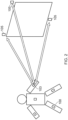
- a second piezoelectric transducer array comprising multiple piezoelectric transducers 105 is provided, respective ones of which configured to receive the second signal, and at least one of which is configured to generate a third signal at the second frequency.
- two transducers for the second array are depicted in figure 1 , it will be appreciated that more can be provided.
- Transducers of the first and/or second array may be provided on clothing, or directly attached to a user or a combination.
- transducers 103 of the first array can send and receive signals at the second frequency to/from transducers 105 of the second array. This enables time of flight measurements to be determined as the time of flight of a second signal to and/or from a transducer 103 from/to a transducer 105 can be obtained with reference to common clock signal that can be provided to transducers in the first and second arrays.
- each transducer in the first and second arrays includes a low energy radio frequency module, such as a Bluetooth low energy (or similar) module (BLE) for example.
- BLE Bluetooth low energy (or similar) module
- One of the transducers 105 in the second array can provide central clock information using a communication channel initiated between transducers using the BLE module. That is, in an example, one of the transducers in the second array can provide a clock signal, and other control information, to respective other ones of the transducers in the first and/or second arrays.
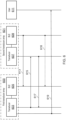
- Figure 2 is a schematic representation of a system according to an example.
- the distribution of transducers of the second array can be extended out to the surrounding environment where some or all of the transducers of the second array, used for triangularisation and TOF generation, can be located.
- Figure 2 depicts all such transducers extended out, although one or more may still be provided in situ on user 100.
- Transducers 103 (five in the example of figures 1 and 2 ) that are used to provide haptic feedback to user 100 remain on the user body. This can therefore minimise the number of the modules on the user and simplify the hardware on the body.
- Figure 5 is a schematic representation of a system according to an example.
- information about a user's (500) surrounding environment can be determined.
- the example of figure 5 is described with reference to an indoor environment, although an outdoor implementation is equally possible.
- a transducer of a first array (which, in the example of figure 5 may comprises only transducer) emits ultrasonic pulses as outlined previously, which are transmitted into the surrounding area.
- the propagation from source 501 to a receiver 503 is multipath, with multiple reflections from objects 505 in the room.
- the secondary pulses that have been received by the sensors 503 contain information about the locations of these reflective surfaces, which in turn contain information regarding the layout of the room such as the locations of furniture and walls.
- the secondary pulse data may also be used to estimate the acoustic reverberation characterisations of the room, which can be communicated to an audio system to optimise a multichannel system, for example.
- a system in response to a distance determination, can be used to provide haptic feedback to a user using transducers of the first array at the first frequency.
- a transducer of the second array can transmit a third signal to a selected piezoelectric transducer of the first piezoelectric transducer array, whereby to cause the said selected piezoelectric transducer of the first piezoelectric transducer array to initiate generation of the first signal at at least one piezoelectric transducer of the first piezoelectric transducer array.
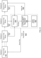
- Transducers 607 generate a third signal, at the second frequency for example, and receive a second signal.
- transducer 607 can provide a clock signal 613 using BLE 609, which is received by BLE 605 of transducers 603 in the first array 600 in order to provide a synchronisation for the system.
- the clock signal 613 may be received by all transducers in the first array 600 by way of their associated BLEs 605.
- transducer 607 emits a third signal 617 at the second frequency.
- the third signal is received at transducer 603 of the first piezoelectric transducer array 600.
- the third signal 617 is configured to cause the said selected piezoelectric transducer 603 of the first piezoelectric transducer array to initiate generation of the first signal 619 at at least one piezoelectric transducer of the first piezoelectric transducer array 600.
- said at least one piezoelectric transducer of the first piezoelectric transducer array 600 includes transducer 603.
- At least one piezoelectric transducer of the first piezoelectric transducer array 600 provides a signal 619 for user 611, whereby to provide haptic feedback to the user 611.
- a transducer that is selected to provide a haptic feedback can be identified using its unique identifier.
- a third signal can encode data representing one or more identifiers of transducers in the first array that are to provide haptic feedback.
- the third signal can further encode data representing the type of haptic feedback signal to be provided by a transducer, as described above for example.
- At least one transducer of the first and/or second arrays 600, 601 can further comprise a memory configured to store machine-readable instructions, and a processor configured to execute the said machine-readable instructions.
- the memory can also store data representing one or more haptic feedback signal profiles.
- Transducer 700 can be a transducer of the first and/or second arrays of figure 6 for example.
- a piezoelectric material 701 can be used to generate the first and second signals.
- application of electric field from power source 703 across the element 701 can cause the element to mechanically deform. Controlling the applied electrical field from source 703 enables the mechanical strain experienced by element 701 to be varied, thus enabling generation of signals at the first or second frequency.
- Power source 703 can also power BLE 705 and the processor 707 and so on of the transducer 700.
- element 701 Upon exposure to a signal at the second frequency, element 701 will mechanically stress leading to generation of an electric charge resulting in a detectable voltage across the element 701 that can be detected by a detector (not shown), and which represents a second signal.
- the detected signal can be decoded by processor 707 to determine, for example, a time stamp and/or identifier, as described above.
- Memory 709 can store data representing one or more haptic profiles.
- a profile can represent a time duration, periodicity, frequency, strength and so on of a haptic feedback signal, with different profiles comprising respective different values for one or more of these signal parameters.
- Respective haptic feedback profiles can be mapped to desired user movements. For example, as described above, one profile can be used to prompt a user to move an arm up, whilst another can be used to prompt a user to move an arm down, and so on.
- Instructions 711 can include instructions to, for example, generate one of the first, second or third signals (either by way of element 701 or BLE 705).
- one device emits an ultrasonic chirp outside the audible frequency range (above 20kHz).
- the other N-I devices receive this pulse at different times depending on their positions. Note that each device can act as both source and receiver at any given time, and only one device is shown as the source for simplicity. In fact, in an example, the devices could emit pulses simultaneously provided their respective pulses have different carrier frequencies, or operate sequentially if they do not.
Landscapes
- Engineering & Computer Science (AREA)
- General Engineering & Computer Science (AREA)
- Theoretical Computer Science (AREA)
- Physics & Mathematics (AREA)
- General Physics & Mathematics (AREA)
- Health & Medical Sciences (AREA)
- Human Computer Interaction (AREA)
- Life Sciences & Earth Sciences (AREA)
- General Health & Medical Sciences (AREA)
- Physical Education & Sports Medicine (AREA)
- Heart & Thoracic Surgery (AREA)
- Medical Informatics (AREA)
- Dentistry (AREA)
- Biophysics (AREA)
- Pathology (AREA)
- Biomedical Technology (AREA)
- Physiology (AREA)
- Oral & Maxillofacial Surgery (AREA)
- Molecular Biology (AREA)
- Surgery (AREA)
- Animal Behavior & Ethology (AREA)
- Public Health (AREA)
- Veterinary Medicine (AREA)
- Radar, Positioning & Navigation (AREA)
- Remote Sensing (AREA)
- User Interface Of Digital Computer (AREA)
Claims (14)
- System zum Bereitstellen einer haptischen Rückmeldung für einen Benutzer, wobei das System Folgendes umfasst:ein erstes piezoelektrisches Wandlerarray (600), das mehrere piezoelektrische Wandler (603) umfasst, von denen jeweilige dazu ausgelegt sind, in vorbestimmten Positionen am Benutzer angeordnet zu sein, und dazu ausgelegt, ein zweites Signal (615) mit einer zweiten Frequenz zu erzeugen und zu übertragen, und von denen mindestens einer dazu ausgelegt ist, ein erstes Signal (619) mit einer ersten Frequenz zu erzeugen; undein zweites piezoelektrisches Wandlerarray (601), das mehrere piezoelektrische Wandler (607) umfasst, von denen jeweilige dazu ausgelegt sind, das zweite Signal (615) zu empfangen, das vom ersten piezoelektrischen Wandlerarray übertragen wird, und von denen mindestens einer zu Folgendem ausgelegt ist:
Erzeugen und Übertragen eines dritten Signals (617) zu mindestens einem piezoelektrischen Wandler (603) des ersten piezoelektrischen Wandlerarrays (600), wodurch der mindestens eine piezoelektrische Wandler des ersten piezoelektrischen Wandlerarrays (600) veranlasst wird, eine Erzeugung des ersten Signals (619) an dem mindestens einen piezoelektrischen Wandler des ersten piezoelektrischen Wandlerarrays (600) zu initiieren, wobei das erste Signal (619) mit der ersten Frequenz geeignet ist, ein haptisches Rückmeldungssignal für einen Benutzer (611) bereitzustellen, wobei das zweite Signal (615) dazu ausgelegt ist, die Position eines Wandlers (603) des ersten piezoelektrischen Wandlerarrays (600) unter Verwendung von Wandlern (607) des zweiten Wandlerarrays (601) zu lokalisieren. - System nach Anspruch 1, wobei das dritte Signal (617) mit der zweiten Frequenz erzeugt wird.
- System nach Anspruch 1 oder 2, wobei das erste piezoelektrische Wandlerarray (600) auf einem Kleidungsstück oder als Teil desselben bereitgestellt wird.
- System nach einem der vorhergehenden Ansprüche, wobei die erste Frequenz eine Frequenz im Bereich von 10-2000 Hz ist.
- System nach einem der vorhergehenden Ansprüche, wobei die zweite Frequenz eine Frequenz im Bereich von 15-50 kHz ist.
- System nach einem der vorhergehenden Ansprüche, das ferner ein Steuermodul zum Empfangen von Rohdaten von jeweiligen piezoelektrischen Wandlern des zweiten piezoelektrischen Wandlerarrays und unter Verwendung der Rohdaten zum Erzeugen von Positionsdaten, die die relative Position der mehreren piezoelektrischen Wandler des ersten piezoelektrischen Wandlerarrays repräsentieren, umfasst.
- System nach Anspruch 6, wobei das Steuermodul dazu ausgelegt ist, die Positionsdaten einem vorbestimmten haptischen Antwortprofil zuzuordnen und haptische Antwortdaten zu erzeugen, die das haptische Antwortprofil repräsentieren.
- System nach Anspruch 7, wobei ein ausgewählter piezoelektrischer Wandler des zweiten piezoelektrischen Wandlerarrays (601) dazu ausgelegt ist, die haptischen Antwortdaten als Teil des dritten Signals (617) zu übertragen.
- System nach einem der Ansprüche 6 bis 8, wobei das Steuermodul dazu ausgelegt ist, jeweilige Zeitstempel aus den Rohdaten zu verwenden, die die Zeiten der Übertragung von zweiten Signalen (615) von jeweiligen piezoelektrischen Wandlern des zweiten piezoelektrischen Wandlerarrays (601) repräsentieren, um eine Flugzeit der zweiten Signale (615) zu bestimmen.
- System nach einem der vorhergehenden Ansprüche, wobei Wandler (603) des ersten piezoelektrischen Wandlerarrays (600) ferner ein jeweiliges niederenergetisches Funkfrequenzkommunikationsmodul umfassen, um ein Datensignal von einem Befehlswandler (607) des zweiten piezoelektrischen Wandlerarrays (601) zu empfangen.
- System nach Anspruch 10, wobei das dritte Signal (617) vom niederenergetischen Funkfrequenzkommunikationsmodul (609) des Befehlswandlers (607) erzeugt wird.
- System nach Anspruch 10, wobei der Befehlswandler dazu ausgelegt ist, Daten zu ausgewählten der niederenergetischen Funkfrequenzkommunikationsmodule der piezoelektrischen Wandler des ersten piezoelektrischen Wandlerarrays zu übertragen, wodurch die entsprechenden piezoelektrischen Wandler des ersten piezoelektrischen Wandlerarrays veranlasst werden, das erste Signal (619) zu erzeugen.
- Verfahren zum Bereitstellen einer haptischen Rückmeldung für einen Benutzer, wobei das Verfahren Folgendes umfasst:Erzeugen eines ersten Signals (619) mit einer ersten Frequenz durch jeweilige Wandler eines ersten piezoelektrischen Wandlerarrays (600), das mehrere piezoelektrische Wandler (603) umfasst,Erzeugen und Übertragen eines zweiten Signals (615) mit einer zweiten Frequenz durch jeweilige Wandler des ersten piezoelektrischen Wandlerarrays, das mehrere piezoelektrische Wandler (603) umfasst, die dazu ausgelegt sind, in vorbestimmten Positionen am Benutzer angeordnet zu sein;Empfangen des zweiten Signals, das vom ersten piezoelektrischen Array übertragen wird, durch jeweilige Wandler eines zweiten piezoelektrischen Wandlerarrays, das mehrere piezoelektrische Wandler umfasst;Erzeugen und Übertragen eines dritten Signals durch jeweilige Wandler des zweiten piezoelektrischen Wandlerarrays zu mindestens einem piezoelektrischen Wandler des ersten piezoelektrischen Wandlerarrays, wodurch der mindestens eine piezoelektrische Wandler des ersten piezoelektrischen Wandlerarrays veranlasst wird, eine Erzeugung des ersten Signals an dem mindestens einen piezoelektrischen Wandler des ersten piezoelektrischen Wandlerarrays zu initiieren, wobei das erste Signal (619) mit der Frequenz geeignet ist, ein haptisches Rückmeldungssignal für einen Benutzer bereitzustellen, wobei das zweite Signal (615) dazu ausgelegt ist, die Position eines Wandlers (603) des ersten piezoelektrischen Wandlerarrays (600) unter Verwendung von Wandlern (607) des zweiten Wandlerarrays (601) zu lokalisieren.
- Nichttransitorisches maschinenlesbares Speichermedium, auf dem Anweisungen codiert sind, die zum Bereitstellen einer haptischen Rückmeldung für einen Benutzer von einem Prozessor ausführbar sind, wobei das maschinenlesbare Speichermedium Anweisungen zum Durchführen der Schritte des Verfahrens von Anspruch 13 umfasst.
Priority Applications (3)
| Application Number | Priority Date | Filing Date | Title |
|---|---|---|---|
| EP19166199.0A EP3716017B1 (de) | 2019-03-29 | 2019-03-29 | Haptische rückmeldung |
| US17/434,216 US11841990B2 (en) | 2019-03-29 | 2020-03-11 | Haptic feedback |
| PCT/EP2020/056444 WO2020200673A1 (en) | 2019-03-29 | 2020-03-11 | Haptic feedback |
Applications Claiming Priority (1)
| Application Number | Priority Date | Filing Date | Title |
|---|---|---|---|
| EP19166199.0A EP3716017B1 (de) | 2019-03-29 | 2019-03-29 | Haptische rückmeldung |
Publications (2)
| Publication Number | Publication Date |
|---|---|
| EP3716017A1 EP3716017A1 (de) | 2020-09-30 |
| EP3716017B1 true EP3716017B1 (de) | 2025-06-25 |
Family
ID=66041225
Family Applications (1)
| Application Number | Title | Priority Date | Filing Date |
|---|---|---|---|
| EP19166199.0A Active EP3716017B1 (de) | 2019-03-29 | 2019-03-29 | Haptische rückmeldung |
Country Status (3)
| Country | Link |
|---|---|
| US (1) | US11841990B2 (de) |
| EP (1) | EP3716017B1 (de) |
| WO (1) | WO2020200673A1 (de) |
Families Citing this family (2)
| Publication number | Priority date | Publication date | Assignee | Title |
|---|---|---|---|---|
| US11624804B2 (en) * | 2020-10-08 | 2023-04-11 | Nokia Technologies Oy | System and method for location determination utilizing direct path information |
| CN113144542A (zh) * | 2021-04-09 | 2021-07-23 | 上海弘遥电子研究开发有限公司 | 一种沉浸式车载健身方法、系统、设备及可读存储介质 |
Citations (1)
| Publication number | Priority date | Publication date | Assignee | Title |
|---|---|---|---|---|
| EP2995096B1 (de) * | 2013-05-08 | 2017-12-20 | Ultrahaptics Ip Ltd | Verfahren und vorrichtung zur herstellung eines akustischen feldes |
Family Cites Families (8)
| Publication number | Priority date | Publication date | Assignee | Title |
|---|---|---|---|---|
| WO2006014810A2 (en) | 2004-07-29 | 2006-02-09 | Kevin Ferguson | A human movement measurement system |
| WO2014114967A1 (en) * | 2013-01-25 | 2014-07-31 | WENNER, Fabian | Self-calibrating motion capture system |
| US10799665B2 (en) | 2015-02-07 | 2020-10-13 | Pauseable Aps | System for tracking motion of a device |
| US10854104B2 (en) | 2015-08-28 | 2020-12-01 | Icuemotion Llc | System for movement skill analysis and skill augmentation and cueing |
| US10055948B2 (en) | 2015-11-30 | 2018-08-21 | Nike, Inc. | Apparel with ultrasonic position sensing and haptic feedback for activities |
| TWI647595B (zh) * | 2016-11-21 | 2019-01-11 | 宏達國際電子股份有限公司 | 人體姿勢偵測系統、穿戴裝置以及方法 |
| US10373452B2 (en) | 2016-11-29 | 2019-08-06 | Immersion Corporation | Targeted haptic projection |
| CN208112614U (zh) * | 2018-01-18 | 2018-11-16 | 加特兰微电子科技(上海)有限公司 | 变压器和射频接收装置 |
-
2019
- 2019-03-29 EP EP19166199.0A patent/EP3716017B1/de active Active
-
2020
- 2020-03-11 WO PCT/EP2020/056444 patent/WO2020200673A1/en not_active Ceased
- 2020-03-11 US US17/434,216 patent/US11841990B2/en active Active
Patent Citations (1)
| Publication number | Priority date | Publication date | Assignee | Title |
|---|---|---|---|---|
| EP2995096B1 (de) * | 2013-05-08 | 2017-12-20 | Ultrahaptics Ip Ltd | Verfahren und vorrichtung zur herstellung eines akustischen feldes |
Also Published As
| Publication number | Publication date |
|---|---|
| WO2020200673A1 (en) | 2020-10-08 |
| US20220187917A1 (en) | 2022-06-16 |
| EP3716017A1 (de) | 2020-09-30 |
| US11841990B2 (en) | 2023-12-12 |
Similar Documents
| Publication | Publication Date | Title |
|---|---|---|
| JP6218785B2 (ja) | 単一のデバイスおよび/または複数のデバイスの測距探知、配向決定、および/または測位のための方法および装置 | |
| US12372645B2 (en) | Transmitting device for use in location determination systems | |
| US11221404B1 (en) | Devices, systems, and methods for radar-based artificial reality tracking using zero-crossing detection | |
| US10133353B2 (en) | Three dimensional tactile feedback system | |
| CN105426024B (zh) | 一种基于超声波聚焦的触觉反馈系统及方法 | |
| CN110023884B (zh) | 可穿戴运动跟踪系统 | |
| US9782669B1 (en) | RF tracking with active sensory feedback | |
| US20100304931A1 (en) | Motion capture system | |
| US20170372524A1 (en) | Rf tracking with active sensory feedback | |
| EP3576427B1 (de) | Haptics-vorrichtung zur erzeugung von richtungsklang und haptischen empfindungen | |
| US12111981B2 (en) | Method and system utilizing phased array beamforming for six degree of freedom tracking for an emitter in augmented reality systems | |
| US11841990B2 (en) | Haptic feedback | |
| US20220179059A1 (en) | Object tracking using beat signal frequency and phase | |
| Shin et al. | Application of precise indoor position tracking to immersive virtual reality with translational movement support | |
| Suzuki et al. | Midair haptic display to human upper body | |
| US11662815B2 (en) | Apparatus, system, and method for detecting user input via hand gestures and arm movements | |
| WO2017125925A1 (en) | Method and system for real-time detection and location of multiple independently moving objects | |
| Carotenuto et al. | Touchless 3D gestural interface using coded ultrasounds | |
| Packi et al. | Wireless acoustic tracking for extended range telepresence | |
| US20250015801A1 (en) | Method and apparatus for ranging finding, orienting and/or positioning of single and/or multiple devices and/or device and method for orientation and positioning | |
| JP6589022B1 (ja) | 位置検出システム | |
| Choudhury | Technical perspective: Is your WiFi a sensor? | |
| JP2025053812A (ja) | 通信システム、情報端末及びプログラム | |
| CN119690272A (zh) | 基于超声换能器阵列的非接触式力触觉反馈系统及方法 | |
| HK40022900A (en) | Six degrees of freedom tracking of objects using sensors |
Legal Events
| Date | Code | Title | Description |
|---|---|---|---|
| PUAI | Public reference made under article 153(3) epc to a published international application that has entered the european phase |
Free format text: ORIGINAL CODE: 0009012 |
|
| STAA | Information on the status of an ep patent application or granted ep patent |
Free format text: STATUS: THE APPLICATION HAS BEEN PUBLISHED |
|
| AK | Designated contracting states |
Kind code of ref document: A1 Designated state(s): AL AT BE BG CH CY CZ DE DK EE ES FI FR GB GR HR HU IE IS IT LI LT LU LV MC MK MT NL NO PL PT RO RS SE SI SK SM TR |
|
| AX | Request for extension of the european patent |
Extension state: BA ME |
|
| STAA | Information on the status of an ep patent application or granted ep patent |
Free format text: STATUS: REQUEST FOR EXAMINATION WAS MADE |
|
| 17P | Request for examination filed |
Effective date: 20210324 |
|
| RBV | Designated contracting states (corrected) |
Designated state(s): AL AT BE BG CH CY CZ DE DK EE ES FI FR GB GR HR HU IE IS IT LI LT LU LV MC MK MT NL NO PL PT RO RS SE SI SK SM TR |
|
| STAA | Information on the status of an ep patent application or granted ep patent |
Free format text: STATUS: EXAMINATION IS IN PROGRESS |
|
| 17Q | First examination report despatched |
Effective date: 20220211 |
|
| GRAP | Despatch of communication of intention to grant a patent |
Free format text: ORIGINAL CODE: EPIDOSNIGR1 |
|
| STAA | Information on the status of an ep patent application or granted ep patent |
Free format text: STATUS: GRANT OF PATENT IS INTENDED |
|
| RIC1 | Information provided on ipc code assigned before grant |
Ipc: A61B 5/11 20060101ALI20240805BHEP Ipc: A61B 5/00 20060101ALI20240805BHEP Ipc: H04W 56/00 20090101ALI20240805BHEP Ipc: G01S 11/14 20060101ALI20240805BHEP Ipc: G01S 5/30 20060101ALI20240805BHEP Ipc: G01S 5/18 20060101ALI20240805BHEP Ipc: G06F 3/01 20060101AFI20240805BHEP |
|
| INTG | Intention to grant announced |
Effective date: 20240904 |
|
| GRAJ | Information related to disapproval of communication of intention to grant by the applicant or resumption of examination proceedings by the epo deleted |
Free format text: ORIGINAL CODE: EPIDOSDIGR1 |
|
| STAA | Information on the status of an ep patent application or granted ep patent |
Free format text: STATUS: EXAMINATION IS IN PROGRESS |
|
| INTC | Intention to grant announced (deleted) | ||
| GRAP | Despatch of communication of intention to grant a patent |
Free format text: ORIGINAL CODE: EPIDOSNIGR1 |
|
| STAA | Information on the status of an ep patent application or granted ep patent |
Free format text: STATUS: GRANT OF PATENT IS INTENDED |
|
| INTG | Intention to grant announced |
Effective date: 20250127 |
|
| GRAS | Grant fee paid |
Free format text: ORIGINAL CODE: EPIDOSNIGR3 |
|
| GRAA | (expected) grant |
Free format text: ORIGINAL CODE: 0009210 |
|
| STAA | Information on the status of an ep patent application or granted ep patent |
Free format text: STATUS: THE PATENT HAS BEEN GRANTED |
|
| AK | Designated contracting states |
Kind code of ref document: B1 Designated state(s): AL AT BE BG CH CY CZ DE DK EE ES FI FR GB GR HR HU IE IS IT LI LT LU LV MC MK MT NL NO PL PT RO RS SE SI SK SM TR |
|
| REG | Reference to a national code |
Ref country code: GB Ref legal event code: FG4D |
|
| REG | Reference to a national code |
Ref country code: CH Ref legal event code: EP |
|
| REG | Reference to a national code |
Ref country code: CH Ref legal event code: EP |
|
| REG | Reference to a national code |
Ref country code: IE Ref legal event code: FG4D |
|
| REG | Reference to a national code |
Ref country code: DE Ref legal event code: R096 Ref document number: 602019071449 Country of ref document: DE |
|
| PG25 | Lapsed in a contracting state [announced via postgrant information from national office to epo] |
Ref country code: FI Free format text: LAPSE BECAUSE OF FAILURE TO SUBMIT A TRANSLATION OF THE DESCRIPTION OR TO PAY THE FEE WITHIN THE PRESCRIBED TIME-LIMIT Effective date: 20250625 |
|
| REG | Reference to a national code |
Ref country code: LT Ref legal event code: MG9D |
|
| PG25 | Lapsed in a contracting state [announced via postgrant information from national office to epo] |
Ref country code: NO Free format text: LAPSE BECAUSE OF FAILURE TO SUBMIT A TRANSLATION OF THE DESCRIPTION OR TO PAY THE FEE WITHIN THE PRESCRIBED TIME-LIMIT Effective date: 20250925 Ref country code: GR Free format text: LAPSE BECAUSE OF FAILURE TO SUBMIT A TRANSLATION OF THE DESCRIPTION OR TO PAY THE FEE WITHIN THE PRESCRIBED TIME-LIMIT Effective date: 20250926 |
|
| PG25 | Lapsed in a contracting state [announced via postgrant information from national office to epo] |
Ref country code: BG Free format text: LAPSE BECAUSE OF FAILURE TO SUBMIT A TRANSLATION OF THE DESCRIPTION OR TO PAY THE FEE WITHIN THE PRESCRIBED TIME-LIMIT Effective date: 20250625 |
|
| PG25 | Lapsed in a contracting state [announced via postgrant information from national office to epo] |
Ref country code: HR Free format text: LAPSE BECAUSE OF FAILURE TO SUBMIT A TRANSLATION OF THE DESCRIPTION OR TO PAY THE FEE WITHIN THE PRESCRIBED TIME-LIMIT Effective date: 20250625 |
|
| PG25 | Lapsed in a contracting state [announced via postgrant information from national office to epo] |
Ref country code: RS Free format text: LAPSE BECAUSE OF FAILURE TO SUBMIT A TRANSLATION OF THE DESCRIPTION OR TO PAY THE FEE WITHIN THE PRESCRIBED TIME-LIMIT Effective date: 20250925 |
|
| PG25 | Lapsed in a contracting state [announced via postgrant information from national office to epo] |
Ref country code: LV Free format text: LAPSE BECAUSE OF FAILURE TO SUBMIT A TRANSLATION OF THE DESCRIPTION OR TO PAY THE FEE WITHIN THE PRESCRIBED TIME-LIMIT Effective date: 20250625 |
|
| REG | Reference to a national code |
Ref country code: NL Ref legal event code: MP Effective date: 20250625 |
|
| PG25 | Lapsed in a contracting state [announced via postgrant information from national office to epo] |
Ref country code: NL Free format text: LAPSE BECAUSE OF FAILURE TO SUBMIT A TRANSLATION OF THE DESCRIPTION OR TO PAY THE FEE WITHIN THE PRESCRIBED TIME-LIMIT Effective date: 20250625 |
|
| PG25 | Lapsed in a contracting state [announced via postgrant information from national office to epo] |
Ref country code: PT Free format text: LAPSE BECAUSE OF FAILURE TO SUBMIT A TRANSLATION OF THE DESCRIPTION OR TO PAY THE FEE WITHIN THE PRESCRIBED TIME-LIMIT Effective date: 20251027 |
|
| REG | Reference to a national code |
Ref country code: AT Ref legal event code: MK05 Ref document number: 1807140 Country of ref document: AT Kind code of ref document: T Effective date: 20250625 |
|
| PG25 | Lapsed in a contracting state [announced via postgrant information from national office to epo] |
Ref country code: IS Free format text: LAPSE BECAUSE OF FAILURE TO SUBMIT A TRANSLATION OF THE DESCRIPTION OR TO PAY THE FEE WITHIN THE PRESCRIBED TIME-LIMIT Effective date: 20251025 |
|
| PG25 | Lapsed in a contracting state [announced via postgrant information from national office to epo] |
Ref country code: AT Free format text: LAPSE BECAUSE OF FAILURE TO SUBMIT A TRANSLATION OF THE DESCRIPTION OR TO PAY THE FEE WITHIN THE PRESCRIBED TIME-LIMIT Effective date: 20250625 Ref country code: SM Free format text: LAPSE BECAUSE OF FAILURE TO SUBMIT A TRANSLATION OF THE DESCRIPTION OR TO PAY THE FEE WITHIN THE PRESCRIBED TIME-LIMIT Effective date: 20250625 |
|
| PG25 | Lapsed in a contracting state [announced via postgrant information from national office to epo] |
Ref country code: CZ Free format text: LAPSE BECAUSE OF FAILURE TO SUBMIT A TRANSLATION OF THE DESCRIPTION OR TO PAY THE FEE WITHIN THE PRESCRIBED TIME-LIMIT Effective date: 20250625 |
|
| PG25 | Lapsed in a contracting state [announced via postgrant information from national office to epo] |
Ref country code: PL Free format text: LAPSE BECAUSE OF FAILURE TO SUBMIT A TRANSLATION OF THE DESCRIPTION OR TO PAY THE FEE WITHIN THE PRESCRIBED TIME-LIMIT Effective date: 20250625 |
|
| PG25 | Lapsed in a contracting state [announced via postgrant information from national office to epo] |
Ref country code: EE Free format text: LAPSE BECAUSE OF FAILURE TO SUBMIT A TRANSLATION OF THE DESCRIPTION OR TO PAY THE FEE WITHIN THE PRESCRIBED TIME-LIMIT Effective date: 20250625 |
|
| PG25 | Lapsed in a contracting state [announced via postgrant information from national office to epo] |
Ref country code: SK Free format text: LAPSE BECAUSE OF FAILURE TO SUBMIT A TRANSLATION OF THE DESCRIPTION OR TO PAY THE FEE WITHIN THE PRESCRIBED TIME-LIMIT Effective date: 20250625 |
|
| PG25 | Lapsed in a contracting state [announced via postgrant information from national office to epo] |
Ref country code: ES Free format text: LAPSE BECAUSE OF FAILURE TO SUBMIT A TRANSLATION OF THE DESCRIPTION OR TO PAY THE FEE WITHIN THE PRESCRIBED TIME-LIMIT Effective date: 20250625 |
|
| PG25 | Lapsed in a contracting state [announced via postgrant information from national office to epo] |
Ref country code: DK Free format text: LAPSE BECAUSE OF FAILURE TO SUBMIT A TRANSLATION OF THE DESCRIPTION OR TO PAY THE FEE WITHIN THE PRESCRIBED TIME-LIMIT Effective date: 20250625 |
|
| PG25 | Lapsed in a contracting state [announced via postgrant information from national office to epo] |
Ref country code: IT Free format text: LAPSE BECAUSE OF FAILURE TO SUBMIT A TRANSLATION OF THE DESCRIPTION OR TO PAY THE FEE WITHIN THE PRESCRIBED TIME-LIMIT Effective date: 20250625 |
|
| PLBE | No opposition filed within time limit |
Free format text: ORIGINAL CODE: 0009261 |
|
| STAA | Information on the status of an ep patent application or granted ep patent |
Free format text: STATUS: NO OPPOSITION FILED WITHIN TIME LIMIT |
|
| REG | Reference to a national code |
Ref country code: CH Ref legal event code: L10 Free format text: ST27 STATUS EVENT CODE: U-0-0-L10-L00 (AS PROVIDED BY THE NATIONAL OFFICE) Effective date: 20260507 |