EP3715915A1 - Scanning device and vehicle-mounted radiation inspection system - Google Patents
Scanning device and vehicle-mounted radiation inspection system Download PDFInfo
- Publication number
- EP3715915A1 EP3715915A1 EP18881541.9A EP18881541A EP3715915A1 EP 3715915 A1 EP3715915 A1 EP 3715915A1 EP 18881541 A EP18881541 A EP 18881541A EP 3715915 A1 EP3715915 A1 EP 3715915A1
- Authority
- EP
- European Patent Office
- Prior art keywords
- scanning device
- limiting component
- vertical detection
- arm
- horizontal supporting
- Prior art date
- Legal status (The legal status is an assumption and is not a legal conclusion. Google has not performed a legal analysis and makes no representation as to the accuracy of the status listed.)
- Pending
Links
- 230000005855 radiation Effects 0.000 title claims abstract description 51
- 238000007689 inspection Methods 0.000 title claims abstract description 11
- 238000001514 detection method Methods 0.000 claims abstract description 137
- 230000035882 stress Effects 0.000 description 5
- 238000010586 diagram Methods 0.000 description 4
- 230000002093 peripheral effect Effects 0.000 description 3
- 230000003044 adaptive effect Effects 0.000 description 2
- 238000000034 method Methods 0.000 description 2
- 238000005381 potential energy Methods 0.000 description 2
- 239000003814 drug Substances 0.000 description 1
- 229940079593 drug Drugs 0.000 description 1
- 230000000694 effects Effects 0.000 description 1
- 239000002360 explosive Substances 0.000 description 1
- 230000006355 external stress Effects 0.000 description 1
- 238000009434 installation Methods 0.000 description 1
- 238000012986 modification Methods 0.000 description 1
- 230000004048 modification Effects 0.000 description 1
- 239000010970 precious metal Substances 0.000 description 1
- 239000007787 solid Substances 0.000 description 1
Images




Classifications
-
- G—PHYSICS
- G01—MEASURING; TESTING
- G01V—GEOPHYSICS; GRAVITATIONAL MEASUREMENTS; DETECTING MASSES OR OBJECTS; TAGS
- G01V5/00—Prospecting or detecting by the use of ionising radiation, e.g. of natural or induced radioactivity
- G01V5/20—Detecting prohibited goods, e.g. weapons, explosives, hazardous substances, contraband or smuggled objects
-
- G—PHYSICS
- G01—MEASURING; TESTING
- G01V—GEOPHYSICS; GRAVITATIONAL MEASUREMENTS; DETECTING MASSES OR OBJECTS; TAGS
- G01V5/00—Prospecting or detecting by the use of ionising radiation, e.g. of natural or induced radioactivity
- G01V5/20—Detecting prohibited goods, e.g. weapons, explosives, hazardous substances, contraband or smuggled objects
- G01V5/22—Active interrogation, i.e. by irradiating objects or goods using external radiation sources, e.g. using gamma rays or cosmic rays
-
- G—PHYSICS
- G01—MEASURING; TESTING
- G01N—INVESTIGATING OR ANALYSING MATERIALS BY DETERMINING THEIR CHEMICAL OR PHYSICAL PROPERTIES
- G01N23/00—Investigating or analysing materials by the use of wave or particle radiation, e.g. X-rays or neutrons, not covered by groups G01N3/00 – G01N17/00, G01N21/00 or G01N22/00
- G01N23/02—Investigating or analysing materials by the use of wave or particle radiation, e.g. X-rays or neutrons, not covered by groups G01N3/00 – G01N17/00, G01N21/00 or G01N22/00 by transmitting the radiation through the material
-
- G—PHYSICS
- G01—MEASURING; TESTING
- G01N—INVESTIGATING OR ANALYSING MATERIALS BY DETERMINING THEIR CHEMICAL OR PHYSICAL PROPERTIES
- G01N2223/00—Investigating materials by wave or particle radiation
- G01N2223/60—Specific applications or type of materials
- G01N2223/631—Specific applications or type of materials large structures, walls
Definitions
- the present disclosure relates to the technical field of scanning detection equipment, and in particular to a radiation scanning device and a vehicle-mounted radiation inspection system.
- the ray scanning system typically includes a horizontal supporting arm and a vertical detection arm. When the ray scanning system is required for a detection work, the vertical detection arm gradually unfolds under the driving of a driving device.
- the vertical detection arm When the vertical detection arm is unfolded to a predetermined position, but the driving device continues to apply a pulling force to the vertical detection arm, the vertical detection arm will twist around its own axis in the horizontal plane, so that a detector arranged on the vertical detection arm cannot accurately receive rays, which leads to errors in detection results and low detection accuracy.
- Some embodiments of the present disclosure provide a radiation scanning device and a vehicle-mounted radiation inspection system.
- the radiation scanning device has high detection precision and can improve the detection accuracy.
- a radiation scanning device including: a horizontal supporting arm; a vertical detection arm, which is rotatably connected to the horizontal supporting arm through a rotating shaft, and has a folded position and an unfolded position relative to the horizontal supporting arm, wherein a central axis line of the vertical detection arm is perpendicular to the rotating shaft; and torque balance components arranged on both sides of the central axis line; and the vertical detection arm is configured to abut against the horizontal supporting arm through the torque balance components at the unfolded position to maintain balance in a horizontal plane.
- the torque balance components include a first limiting component and a second limiting component, which fit with each other, one of the first limiting component and the second limiting component is arranged on the horizontal supporting arm, and the other is arranged on the vertical detection arm.
- the first limiting component includes a limiting column
- the second limiting component includes a limiting block
- the first limiting component includes a limiting block
- the second limiting component includes a limiting column
- the top of the limiting column includes a spherical surface
- the limiting block includes a concave surface or a convex surface matching the spherical surface.
- the first limiting component is of a columnar structure having a connection end and a free end, the diameter of the free end is greater than the diameter of the connection end, and the second limiting component includes an accommodating hole provided with an opening and for accommodating the free end.
- the second limiting component includes a body and a snap ring connected to the body, the accommodating hole is formed in the body, the free end is configured to be inserted into the accommodating hole by passing through the snap ring for clamping the free end.
- the snap ring includes a plurality of arc-shaped segments, each of the plurality of arc-shaped segments is slidably connected to the body, and each the plurality of arc-shaped segments is configured to reciprocate along the radial direction of the accommodating hole.
- a positioning hole is formed in an area corresponding to each of the plurality of arc-shaped segments on the body, the positioning hole communicates with the accommodating hole, each of the plurality of arc-shaped segments includes a convex portion inserted into the positioning hole, the second limiting component further includes a reset member arranged in the positioning hole, and the reset member abuts against the convex portion.
- the reset member includes a spring and a spring seat connected to the spring, the spring seat is connected to the body, and the spring is arranged between the convex portion and the spring seat.
- the second limiting component further includes a pressure sensor arranged on the hole wall of the accommodating hole.
- the radiation scanning device further includes a first magnetic component and a second magnetic component, which are configured to be attracted to each other, the first magnetic component is arranged on the horizontal supporting arm, and the second magnetic component is arranged on the vertical detection arm.
- the radiation scanning device includes the horizontal supporting arm, the vertical detection arm and the torque balance components.
- the horizontal supporting arm is rotatably connected to the vertical detection arm through a rotating shaft.
- the vertical detection arm has the folded position and the unfolded position relative to the horizontal supporting arm.
- Both the vertical detection arm and the horizontal supporting arm have central axis lines perpendicular to the rotating shaft.
- the central axis lines of the two are parallel to each other.
- the central axis lines of the two are perpendicular to each other.
- the torque balance components are arranged on the both sides of the central axis line of the vertical detection arm.
- the vertical detection arm When the vertical detection arm rotates to a vertical state, the vertical detection arm abuts against the horizontal supporting arm through the torque balance components. Under the action of the torque balance components, the respective torques on the both sides of the central axis line of the vertical detection arm are equal, and the directions are opposite, so that the vertical detection arm does not twist horizontally around its own central axis line, but maintains a balanced state, in this way, the vertical detection arm is maintained at an optimal detection position as a whole, and the detection accuracy is improved.
- the embodiments of the present disclosure provide a vehicle-mounted radiation inspection system, including a vehicle body and the above-mentioned radiation scanning device arranged on the vehicle body.
- connection can be a fixed connection and can also be a detachable connection or an integral connection; and the connection can be a direct connection and can also be a connection via an intermediate medium.
- connection can be a fixed connection and can also be a detachable connection or an integral connection; and the connection can be a direct connection and can also be a connection via an intermediate medium.
- the radiation scanning device is mainly used for scanning and detecting objects to be detected, such as containers or vehicles, so as to quickly and effectively check whether target articles exist in the containers or the vehicles.
- the radiation scanning device includes a vertical supporting arm 1, a horizontal supporting arm 2 and a vertical detection arm 3, which are sequentially connected.
- the vertical detection arm 3 has a folded position and an unfolded position relative to the horizontal supporting arm 2.
- the vertical supporting arm 1 can switch from a horizontal state to a vertical state, meanwhile, the vertical supporting arm 1 and the horizontal supporting arm 2 are perpendicular to each other, and the vertical detection arm 3 and the horizontal supporting arm 2 are perpendicular to each other.
- the vertical supporting arm 1, the horizontal supporting arm 2 and the vertical detection arm 3 can form a frame-type structure.
- the object to be detected can pass through the frame-type structure to be scanned and detected by rays.
- the vertical supporting arm 1, the horizontal supporting arm 2 and the vertical detection arm 3 in the present embodiment can be of solid columnar structures or hollow columnar structures.
- the vertical detection arm 3 and the horizontal supporting arm 2 in the present embodiment are rotationally connected through a rotating shaft 98.
- the vertical detection arm 3 can rotate relative to the horizontal supporting arm 2 to switch between the folded position and the unfolded position.
- the vertical detection arm 3 and the horizontal supporting arm 2 in the present embodiment both have central axis lines 99 perpendicular to the rotating shaft 98.
- their respective central axis lines 99 are parallel to each other.
- their respective central axis lines 99 are perpendicular to each other.
- the respective central axis lines 99 of the vertical detection arm 3 and the horizontal supporting arm 2 are located in the same plane.
- a detector 31 is arranged on the vertical detection arm 3 in the present embodiment.
- the detector 31 is used for receiving the rays.
- the radiation scanning device according to the embodiment of the present disclosure further includes torque balance components 4.
- the torque balance components 4 can keep the vertical detection arm 3 at the unfolded position at a predetermined position to prevent the vertical detection arm 3 from twisting in the horizontal plane, thereby avoiding a deviation of ray receiving angle of the detector 31, and ensuring that the detector 31 remains at an optimal ray receiving position, in order to accurately receive the ray dose passing through the object to be detected and to guarantee the detection accuracy of the vertical detection arm 3.
- the torque balance components 4 in the present embodiment are arranged on both sides of the central axis line 99 of the vertical detection arm 3, so that the torque balance components 4 can apply acting forces to the areas of the vertical detection arm 3 on the both sides of the central axis line 99.
- the horizontal torques formed by the respective acting forces in the areas on the both sides of the central axis line 99 of the vertical detection arm 3 deviating from the central axis 99 are equal, so that the vertical detection arm 3 at the unfolded position does not twist around central axis line 99 thereof in the horizontal plane due to the unbalanced stresses in the areas on the both sides of the central axis line 99.
- the detector 31 arranged in the vertical detection arm 3 is at a predetermined ray receiving position, and the ray receiving angle is optimal to ensure the detection accuracy.
- the torque balance components 4 in the present embodiment include a first limiting component 41 and a second limiting component 42, which fit with each other.
- the first limiting component 41 and the second limiting component 42 limit each other, so that accurate positioning of the vertical detection arm 3 can be ensured.
- One of the first limiting component 41 and the second limiting component 42 is arranged on the horizontal supporting arm 2, and the other is arranged on the vertical detection arm 3.
- the first limiting component 41 abuts against the second limiting component 42, thereby preventing the vertical detection arm 3 from continuing to unfold and maintaining the vertical detection arm 3 in the vertical state, at this time, the central axis line 99 of the vertical detection arm 3 is perpendicular to the central axis line 99 of the horizontal supporting arm 2.
- the stresses in the areas of the vertical detection arm 3 on the both sides of its own central axis line 99 are balanced, and the generated torques are equal to prevent the vertical detection arm 3 from twisting in the horizontal plane.
- the end portion of the vertical detection arm 3 close to the horizontal supporting arm 2 includes a first mounting surface and a second mounting surface.
- the first mounting surface and the second mounting surface are respectively located on the both sides of the own central axis line 99 of the vertical detection arm 3.
- the first mounting surface and the second mounting surface are both provided with the first limiting components 41.
- the second limiting components 42 are arranged at the end portion of the horizontal supporting arm 2 close to the vertical detection arm 3, and are arranged corresponding to the number and positions of the first limiting components 41.
- the horizontal torque formed by the pressure stress on the first mounting surface of the vertical detection arm 3 deviating from the central axis line 99 of the vertical detection arm 3 is equal to the horizontal torque formed by the pressure stress on the second mounting surface of the vertical detection arm 3 deviating from the central axis line 99 of the vertical detection arm 3, so that the vertical detector 31 keeps balance in the horizontal plane, thereby preventing the vertical detection arm 3 from twisting horizontally around central axis line 99 thereof.
- the radiation scanning device includes a driving rod 5.
- the horizontal supporting arm 2 is of a hollow columnar structure.
- the driving rod 5 is arranged in the horizontal supporting arm 2.
- the axis line of the driving rod 5 is parallel or coincident with the central axis line 99 of the horizontal supporting arm 2.
- the free end of the driving rod 5 is hinged with the end portion of the vertical detection arm 3 that is rotationally connected to the horizontal supporting arm 2.
- the driving rod 5 includes a plurality of telescopic segments. Each of the telescopic segments of the driving rod 5 performs telescopic motion to drive the vertical detection arm 3 to rotate around the rotating shaft 98.
- the first mounting surface and the second mounting surface of the vertical detection arm 3 are respectively located on the both sides of the driving rod 5.
- the number of the first limiting components 41 is two, one of which is arranged on the first mounting surface, and the other is arranged on the second mounting surface.
- the number of the second limiting components 42 is two, one of which is arranged on one side of the driving rod 5, and the other is arranged on the other side of the driving rod 5.
- the first limiting component 41 is arranged on the horizontal supporting arm 2, and the second limiting component 42 is arranged on the vertical detection arm 3.
- the first limiting component 41 includes a limiting column.
- the second limiting component 42 includes a limiting block.
- the limiting column in the present embodiment includes two opposite end portions, one of which is a connecting portion 411, and the other is an abutting portion 412.
- the connection portion 411 is connected and fixed with the horizontal supporting arm 2.
- the abutting portion 412 is in a free state.
- the limiting block can directly abut against the abutting portion 412 of the limiting column, so as to realize the mutual limit of the horizontal supporting arm 2 and the vertical detection arm 3 and to ensure that the central axis line 99 of the horizontal supporting arm 2 and the central axis line 99 of the vertical detection arm 3 are perpendicular to each other.
- the connecting portion 411 is provided with external threads to form a threaded connection with the horizontal supporting arm 2.
- the end face of the abutting portion 412 is a spherical surface.
- the limiting block includes a concave surface or a convex surface matching the spherical surface.
- the limiting block includes a fixing lug. The fixing lug of the limiting block is connected and fixed with the vertical detection arm 3 by screws. When the vertical detection arm 3 rotates to the unfolded position, the concave surface or convex surface of the limiting block directly abuts rigidly against the spherical surface of the limiting column.
- first limiting component 41 can also be arranged on the vertical detection arm 3, and the second limiting component 42 is arranged on the horizontal supporting arm 2.
- the structures of the first limiting component 41 and the second limiting component 42 are the same as those in the foregoing embodiment, and thus details are not described herein again.
- the first limiting component 41 is arranged on the vertical detection arm 3, and the second limiting component 42 is arranged on the horizontal supporting arm 2.
- the first limiting component 41 includes a connection end 411' and a free end 412'.
- the radial dimension of the free end 412' is greater than the radial dimension of the connection end 411'.
- the second limiting component 42 includes an accommodating hole 421 with an opening. The accommodating hole 421 is used for accommodating the free end 412' of the first limiting component 41.
- the free end 412' of the first limiting component 41 can be inserted into the accommodating hole 421 of the second limiting component 42 and pressed against the hole wall of the accommodating hole 421, thereby achieving the mutual limit of the horizontal supporting arm 2 and the vertical detection arm 3, and ensuring that the central axis line 99 of the horizontal supporting arm 2 and the central axis line 99 of the vertical detection arm 3 are perpendicular to each other.
- the vertical detector 31 at the unfolded position keeps balance in the horizontal plane, thereby preventing the vertical detection arm 3 from twisting horizontally around its own central axis line 99.
- the first limiting component 41 is of a stepped columnar structure.
- the diameter of the free end 412' is greater than the diameter of the connection end 411'.
- the free end 412' can be a frustum structure or a cylindrical structure.
- the accommodating hole 421 of the second limiting component 42 can be a tapered hole or a cylindrical blind hole.
- the second limiting component 42 includes a body 422 and a snap ring 423 connected to the body 422.
- the accommodating hole 421 is formed in the body 422.
- the snap ring 423 is arranged on the moving path of the free end 412'.
- the snap ring 423 can be clamped with the free end 412' to lock the free end 412' in the accommodating hole 421, so as to prevent the free end 412' from detaching from the accommodating hole 421, when the vertical detection arm 3 shakes due to the impact of an external force, therefore, it is ensured that the position of the vertical detection arm 3 remains stable, and the detector 31 normally receives the rays.
- the snap ring 423 in the present embodiment includes a plurality of arc-shaped segments 423a.
- Each of the plurality of arc-shaped segments 423a is slidably connected to the body 422.
- Each of the plurality of arc-shaped segment 423a can reciprocate along the radial direction of the accommodating hole 421.
- the plurality of arc-shaped segments 423a are distributed around the axis of the accommodating hole 421 and form a complete circular snap ring 423.
- the plurality of arc-shaped segments 423a are enclosed to form a through hole.
- the free end 412' of the first limiting component 41 Before entering the accommodating hole 421, the free end 412' of the first limiting component 41 firstly pushes each of the plurality of arc-shaped segments 423a to move along the radial direction of the accommodating hole 421 toward the direction away from the axis of the accommodating hole 421, so as to enlarge the diameter of the through hole and avoid the opening of the accommodating hole 421.
- each of the plurality of arc-shaped segments 423a moves along the radial direction of the accommodating hole 421 toward the direction close to the axis of the accommodating hole 421, so as to reduce the diameter of the through hole, and then the clamp and lock the free end 412' to prevent the vertical detection arm 3 from driving the free end 412' to withdraw from the accommodating hole 421 while shaking.
- the snap ring 423 includes two, three or four arc-shaped segments 423a.
- a positioning hole 422a is formed in an area corresponding to each of the plurality of arc-shaped segments 423a on the body 422.
- the positioning hole 422a communicates with the accommodating hole 421.
- the axis of the positioning hole 422a is perpendicular to the axis of the accommodating hole 421.
- Each of the plurality of arc-shaped segments 423a includes a convex portion 428 inserted into the positioning hole 422a.
- the convex portion 428 of each of the plurality of arc-shaped segments 423a moves along the axial direction of the positioning hole 422a.
- the convex portion 428 of each of the plurality of arc-shaped segments 423a is limited by the positioning hole 422a to ensure that each of the plurality of arc-shaped segments 423a maintains a stable position during the reciprocating process.
- the arc-shaped segment 423a includes a first inclined plane 424, a transitional surface 425 and a second inclined plane 426, which are successively distributed along the axial direction of the accommodating hole 421.
- the end face of the free end 412' of the first limiting component 41 away from the connection end 411' is provided with a slope surface having the same gradient as the first inclined plane 424, so that the slope surface of the free end 412' of the first limiting component 41 and the first inclined plane 424 slide relatively, and then it is easier to push the arc-shaped segment 423a to move into the accommodating hole 421.
- the end face of the free end 412' of the first limiting component 41 facing to the connection end 411' is provided with a slope surface having the same gradient as the second inclined plane 426, so that after the free end 412' is inserted into the accommodating hole 421, the second inclined plane 426 is fitted with the slope surface.
- the vertical detection arm 3 can drive the free end 412' of the first limiting component 41 to move, so that the slope surface of the free end 412' and the second inclined plane 426 slide relatively. In this way, the free end 412' of the first limiting component 41 can push the arc-shaped segment 423a to move and withdraw from the accommodating hole 421 with less effort.
- the transitional surface 425 is an arc surface, so that during the process of inserting or withdrawing the free end 412' of the first limiting component 41 from the accommodating hole 421, the relative sliding friction resistance between the transitional surface 425 and the peripheral surface of the free end 412' is small, which is conducive to inserting into or pulling out the free end 412' from the accommodating hole 421, and at the same time, the plurality of arc-shaped segments 423a generate no scratch on the peripheral surface of the free end 412', thereby ensuring the integrity of the peripheral surface of the free end 412'.
- the second limiting component 42 in the present embodiment further includes a reset member 427 arranged in the positioning hole 422a.
- the reset member 427 abuts against the convex portion 428.
- the reset member 427 can drive the arc-shaped segment 423a to automatically reset, thereby improving the degree of automation.
- the reset member 427 actively drives the arc-shaped segment 423a to move toward the axis of the accommodating hole 421 along the radial direction of the accommodating hole 421, so that the arc-shaped segment 423a returns to the initial position to clamp the free end 412'.
- the reset member 427 includes a spring 427a and a spring seat 427b connected to the spring 427a.
- the spring seat 427b is connected to the body 422.
- the spring seat 427b can be connected to the body 422 by screws, or, the spring seat 427b can be provided with threads, and the positioning hole 422a is provided with internal threads.
- the spring seat 427b is in threaded connection with the body 422 directly.
- the spring 427a is arranged between the convex portion 428 and the spring seat 427b. One end of the spring 427a is connected to the convex portion 428 of the arc-shaped segment 423a, and the other end thereof is connected to the spring seat 427b.
- the convex portion 428 of the arc-shaped segment 423a can compress the spring 427a, so that the spring 427a accumulates elastic potential energy.
- the spring 427a releases the elastic potential energy to drive the arc-shaped segment 423a to move toward the axis of the accommodating hole 421 along the radial direction of the accommodating hole 421.
- the spring 427a is a coil spring.
- the second limiting component 42 in the second embodiment further includes a pressure sensor 429.
- the pressure sensor 429 is arranged on the hole wall of the accommodating hole 421 and is used for detecting a pressure value of the free end 412' of the first limiting component 41 abutting against the hole wall of the accommodating hole 421, so as to judge whether the free end 412' of the first limiting component 41 is accurately inserted into the accommodating hole 421 and reaches a predetermined position, then, whether the vertical detection arm 3 is accurately unfolded to the predetermined unfolded position is judged, and the level of automation of the radiation scanning device is improved.
- the pressure sensor 429 can be a pressure strain gauge, and the pressure strain gauge is attached to the hole wall of the accommodating hole 421.
- the pressure strain gauge is attached to a wall surface of the tapered hole.
- the accommodating hole 421 is a cylindrical blind hole
- the accommodating hole 421 includes a bottom wall and a side wall. The pressure strain gauge is attached to the bottom wall.
- the radiation scanning device in the present embodiment further includes a first magnetic component 6 and a second magnetic component 7.
- the first magnetic component 6 is arranged on the horizontal supporting arm 2.
- the second magnetic component 7 is arranged on the vertical detection arm 3.
- the first limiting component 41 and the second limiting component 42 fit to locate the position of the vertical detecting arm 3, and at the same time, the first magnetic component 6 and the second magnetic component 7 are connected by mutual suction.
- the first magnetic component 6 and the second magnetic component 7 after the suction connection can keep a stable relative position between the horizontal supporting arm 2 and the vertical detection arm 3.
- the vertical detection arm 3 shakes due to the impact of external stress, the vertical detection arm 3 is connected to the horizontal supporting arm 2 as a whole through the first magnetic component 6 and the second magnetic component 7, therefore the shaking amplitude of the vertical detection arm 3 is small, and shaking of the vertical detection arm 3 can be stopped quickly to avoid the situation that the vertical detection arm 3 cannot perform the scanning detection work due to the excessive shaking time, thereby improving the adaptive capacity and the detection working efficiency of the vertical detection arm 3, and meanwhile avoiding the first limiting component 41 and the second limiting component 42 detaching from the connection state due to the excessive shaking amplitude of the vertical detection arm 3.
- the first magnetic component 6 and the second magnetic component 7 are located above the first limiting component 41 and the second limiting component 42.
- the first magnetic component 6 includes a first connecting rod and a first magnet.
- the first magnet is of a strip-shaped structure and extends along the axis of the rotating shaft 98.
- the second magnetic component 7 includes a second connecting rod and a second magnet.
- the second magnet is of a strip-shaped structure and extends along the axis of the rotating shaft 98.
- the first magnetic component 6 includes a first connecting rod and a first electromagnet.
- the first electromagnet is of a strip-shaped structure and extends along the axis of the rotating shaft 98.
- the second magnetic component 7 includes a second connecting rod and a second electromagnet.
- the second electromagnet is of a strip-shaped structure and extends along the axis of the rotating shaft 98.
- the radiation scanning device further includes a rotating platform arranged at one end of the vertical supporting arm 1 away from the horizontal supporting arm 2 and an oil cylinder connecting the rotating platform and the vertical supporting arm 1.
- One end of the oil cylinder is rotationally connected to the rotating platform through a rotating shaft, and the other end thereof is rotationally connected to the vertical supporting arm 1 through a rotating shaft.
- the oil cylinder can drive the vertical supporting arm 1 to fold to the horizontal state or unfold to the vertical state.
- the radiation scanning device includes the horizontal supporting arm 2, the vertical detection arm 3 and the torque balance components 4.
- the horizontal supporting arm 2 is rotatably connected to the vertical detection arm 3 through the rotating shaft 98.
- the vertical detection arm 3 has the folded position and the unfolded position relative to the horizontal supporting arm 2.
- Both the vertical detection arm 3 and the horizontal supporting arm 2 have central axis lines 99 perpendicular to the rotating shaft 98.
- the central axis lines 99 of the two are parallel to each other.
- the central axis lines 99 of the two are perpendicular to each other.
- the torque balance components 4 are arranged on the both sides of the central axis line 99 of the vertical detection arm 3.
- the vertical detection arm 3 rotates to the vertical state, the vertical detection arm 3 abuts against the horizontal supporting arm 2 through the torque balance components 4.
- the respective torques in the areas on the both sides of the central axis line 99 of the vertical detection arm 3 are equal, and the directions are opposite, so that the vertical detection arm 3 does not twist horizontally around central axis line 99 thereof, but maintains a balanced state, in this way, the vertical detection arm 3 is maintained at an optimal detection position as a whole, and the detection accuracy is improved.
- the embodiment of the present disclosure further provides a vehicle-mounted radiation inspection system, including a vehicle body 8 and the radiation scanning device in the above embodiments arranged on the vehicle body 8.
- the vehicle body 8 can carry the radiation scanning device to move to realize rapid changing site, and a scanning channel is quickly constructed at a predetermined position to carry out scanning detection work.
- the vehicle-mounted radiation inspection system is flexible and high in adaptive capacity. Since the vertical detection arm 3 of the radiation scanning device can still maintain a stable position at the unfolded position, the detection accuracy of the vehicle-mounted radiation inspection system is high.
Landscapes
- Physics & Mathematics (AREA)
- General Physics & Mathematics (AREA)
- Life Sciences & Earth Sciences (AREA)
- Geophysics (AREA)
- General Life Sciences & Earth Sciences (AREA)
- High Energy & Nuclear Physics (AREA)
- Analytical Chemistry (AREA)
- General Health & Medical Sciences (AREA)
- Immunology (AREA)
- Pathology (AREA)
- Biochemistry (AREA)
- Chemical & Material Sciences (AREA)
- Health & Medical Sciences (AREA)
- Manipulator (AREA)
- A Measuring Device Byusing Mechanical Method (AREA)
- Apparatus For Radiation Diagnosis (AREA)
Abstract
Description
- The present application claims the priority of Chinese Application No.
201711167451.4 - The present disclosure relates to the technical field of scanning detection equipment, and in particular to a radiation scanning device and a vehicle-mounted radiation inspection system.
- With the growth of global trade, the quantity required for containers is increasing. More goods are transported and traded in containers. In order to prevent contraband such as weapons, explosives, illegal drugs or precious metals from being hidden in the containers, but the containers cannot be opened for detection at the same time, the problem can be well solved by the nonintrusive detection to the containers using a ray scanning system. The ray scanning system typically includes a horizontal supporting arm and a vertical detection arm. When the ray scanning system is required for a detection work, the vertical detection arm gradually unfolds under the driving of a driving device. When the vertical detection arm is unfolded to a predetermined position, but the driving device continues to apply a pulling force to the vertical detection arm, the vertical detection arm will twist around its own axis in the horizontal plane, so that a detector arranged on the vertical detection arm cannot accurately receive rays, which leads to errors in detection results and low detection accuracy.
- Some embodiments of the present disclosure provide a radiation scanning device and a vehicle-mounted radiation inspection system. The radiation scanning device has high detection precision and can improve the detection accuracy.
- One aspect of the embodiment of the present disclosure provides a radiation scanning device, including: a horizontal supporting arm; a vertical detection arm, which is rotatably connected to the horizontal supporting arm through a rotating shaft, and has a folded position and an unfolded position relative to the horizontal supporting arm, wherein a central axis line of the vertical detection arm is perpendicular to the rotating shaft; and torque balance components arranged on both sides of the central axis line; and the vertical detection arm is configured to abut against the horizontal supporting arm through the torque balance components at the unfolded position to maintain balance in a horizontal plane.
- According to one aspect of the embodiments of the present disclosure, the torque balance components include a first limiting component and a second limiting component, which fit with each other, one of the first limiting component and the second limiting component is arranged on the horizontal supporting arm, and the other is arranged on the vertical detection arm.
- According to one aspect of the embodiments of the present disclosure, the first limiting component includes a limiting column, and the second limiting component includes a limiting block, or, the first limiting component includes a limiting block, and the second limiting component includes a limiting column.
- According to one aspect of the embodiments of the present disclosure, the top of the limiting column includes a spherical surface, and the limiting block includes a concave surface or a convex surface matching the spherical surface.
- According to one aspect of the embodiments of the present disclosure, the first limiting component is of a columnar structure having a connection end and a free end, the diameter of the free end is greater than the diameter of the connection end, and the second limiting component includes an accommodating hole provided with an opening and for accommodating the free end.
- According to one aspect of the embodiments of the present disclosure, the second limiting component includes a body and a snap ring connected to the body, the accommodating hole is formed in the body, the free end is configured to be inserted into the accommodating hole by passing through the snap ring for clamping the free end.
- According to one aspect of the embodiments of the present disclosure, the snap ring includes a plurality of arc-shaped segments, each of the plurality of arc-shaped segments is slidably connected to the body, and each the plurality of arc-shaped segments is configured to reciprocate along the radial direction of the accommodating hole.
- According to one aspect of the embodiments of the present disclosure, a positioning hole is formed in an area corresponding to each of the plurality of arc-shaped segments on the body, the positioning hole communicates with the accommodating hole, each of the plurality of arc-shaped segments includes a convex portion inserted into the positioning hole, the second limiting component further includes a reset member arranged in the positioning hole, and the reset member abuts against the convex portion.
- According to one aspect of the embodiments of the present disclosure, the reset member includes a spring and a spring seat connected to the spring, the spring seat is connected to the body, and the spring is arranged between the convex portion and the spring seat.
- According to one aspect of the embodiments of the present disclosure, the second limiting component further includes a pressure sensor arranged on the hole wall of the accommodating hole.
- According to one aspect of the embodiments of the present disclosure, the radiation scanning device further includes a first magnetic component and a second magnetic component, which are configured to be attracted to each other, the first magnetic component is arranged on the horizontal supporting arm, and the second magnetic component is arranged on the vertical detection arm.
- The radiation scanning device according to the embodiment of the present disclosure includes the horizontal supporting arm, the vertical detection arm and the torque balance components. The horizontal supporting arm is rotatably connected to the vertical detection arm through a rotating shaft. The vertical detection arm has the folded position and the unfolded position relative to the horizontal supporting arm. Both the vertical detection arm and the horizontal supporting arm have central axis lines perpendicular to the rotating shaft. When the vertical detection arm and the horizontal supporting arm are at the folded position, the central axis lines of the two are parallel to each other. When the vertical detection arm and the horizontal supporting arm are at the unfolded position, the central axis lines of the two are perpendicular to each other. The torque balance components are arranged on the both sides of the central axis line of the vertical detection arm. When the vertical detection arm rotates to a vertical state, the vertical detection arm abuts against the horizontal supporting arm through the torque balance components. Under the action of the torque balance components, the respective torques on the both sides of the central axis line of the vertical detection arm are equal, and the directions are opposite, so that the vertical detection arm does not twist horizontally around its own central axis line, but maintains a balanced state, in this way, the vertical detection arm is maintained at an optimal detection position as a whole, and the detection accuracy is improved.
- In another aspect, the embodiments of the present disclosure provide a vehicle-mounted radiation inspection system, including a vehicle body and the above-mentioned radiation scanning device arranged on the vehicle body.
- The features, advantages and technical effects of the exemplary embodiments of the present disclosure will be described below with reference to the drawings.
-
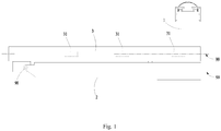
Fig. 1 is a top view of a radiation scanning device in a folded state according to one embodiment of the present disclosure; -
Fig. 2 is a perspective view of a radiation scanning device in a working state according to one embodiment of the present disclosure; -
Fig. 3 is a schematic diagram of a local structure of a radiation scanning device according to one embodiment of the present disclosure; -
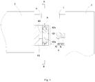
Fig. 4 is a schematic diagram of a local structure of a radiation scanning device according to another embodiment of the present disclosure; -
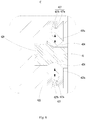
Fig. 5 is a partial enlarged drawing of a site A inFig. 4 ; -
Fig. 6 is a schematic diagram of a sectional structure of a site B-B inFig. 4 ; -
Fig. 7 is a structural schematic diagram of a connection state of a horizontal supporting arm and a vertical detection arm according to one embodiment of the present disclosure; -
Fig. 8 is a partial enlarged drawing of a site C inFig. 7 ; -
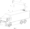
Fig. 9 is a perspective view of a vehicle-mounted radiation inspection system in a working state according to one embodiment of the present disclosure. - In the drawings, the drawings are not drawn to actual scale.
-
- 1, vertical supporting arm; 2, horizontal supporting arm; 3, vertical detection arm; 31. detector;
- 4, torque balance components; 41, first limiting component; 411, connecting portion; 412, abutting portion; 411', connection end; 412', free end; 42, second limiting component; 421 accommodating hole; 422, body; 422a, positioning hole; 423, snap ring; 423a, arc-shaped segment; 424, first inclined plane; 425, transitional surface; 426, second inclined plane; 427, reset member; 427a, spring; 427b, spring seat; 428, convex portion; 429, pressure sensor; 5, driving rod; 6, first magnetic component; 7, second magnetic component; 8, vehicle body; 98, rotating shaft; 99, central axis line.
- The embodiments of the present disclosure are described in further detail below with reference to the drawings and embodiments. The detailed description and drawings of the following embodiments are used to exemplarily illustrate the principle of the present disclosure, but cannot be used to limit the scope of the present disclosure, that is, the present disclosure is not limited to the described embodiments.
- In the description of the present disclosure, it should be noted that, unless otherwise stated, the meaning of "plurality" is two or more; orientation or positional relationships indicates by terms "upper", "lower", "left", "right", "inner", "outer" and the like are only for the convenience of describing the present disclosure and simplifying the description, rather than indicating or implying that the device or element referred to must have a particular orientation or be constructed and operated in a particular orientation, and thus cannot be interpreted as limitations to the present disclosure. In addition, the terms "first", "second" and the like are used for descriptive purposes only, and should not be interpreted as indicating or implying relative importance.
- In the description of the present disclosure, it should also be noted that the terms "installation", "connected" and "connection" should be understood in a broad sense unless otherwise specified and limited, for example, the connection can be a fixed connection and can also be a detachable connection or an integral connection; and the connection can be a direct connection and can also be a connection via an intermediate medium. For those of ordinary skill in the art, the specific meanings of the above terms in the present disclosure can be understood according to specific situations.
- In order to better understand the present disclosure, a radiation scanning device according to an embodiment of the present disclosure will be described in detail below with reference to
Fig. 1 to Fig. 9 . - The radiation scanning device according to the embodiment of the present disclosure is mainly used for scanning and detecting objects to be detected, such as containers or vehicles, so as to quickly and effectively check whether target articles exist in the containers or the vehicles.
- As shown in
Fig. 1 andFig. 2 , the radiation scanning device according to the embodiment of the present disclosure includes a vertical supportingarm 1, a horizontal supportingarm 2 and avertical detection arm 3, which are sequentially connected. Thevertical detection arm 3 has a folded position and an unfolded position relative to the horizontal supportingarm 2. When the radiation scanning device switches from a folded state to an unfolded state, the vertical supportingarm 1 can switch from a horizontal state to a vertical state, meanwhile, the vertical supportingarm 1 and the horizontal supportingarm 2 are perpendicular to each other, and thevertical detection arm 3 and the horizontal supportingarm 2 are perpendicular to each other. In this way, the vertical supportingarm 1, the horizontal supportingarm 2 and thevertical detection arm 3 can form a frame-type structure. The object to be detected can pass through the frame-type structure to be scanned and detected by rays. Optionally, the vertical supportingarm 1, the horizontal supportingarm 2 and thevertical detection arm 3 in the present embodiment can be of solid columnar structures or hollow columnar structures. - The
vertical detection arm 3 and the horizontal supportingarm 2 in the present embodiment are rotationally connected through arotating shaft 98. Thevertical detection arm 3 can rotate relative to the horizontal supportingarm 2 to switch between the folded position and the unfolded position. Thevertical detection arm 3 and the horizontal supportingarm 2 in the present embodiment both havecentral axis lines 99 perpendicular to therotating shaft 98. When thevertical detection arm 3 and the horizontal supportingarm 2 are at the folded position, their respectivecentral axis lines 99 are parallel to each other. When thevertical detection arm 3 and the horizontal supportingarm 2 are at the unfolded position, their respectivecentral axis lines 99 are perpendicular to each other. Preferably, the respectivecentral axis lines 99 of thevertical detection arm 3 and the horizontal supportingarm 2 are located in the same plane. - A
detector 31 is arranged on thevertical detection arm 3 in the present embodiment. Thedetector 31 is used for receiving the rays. The radiation scanning device according to the embodiment of the present disclosure further includestorque balance components 4. Thetorque balance components 4 can keep thevertical detection arm 3 at the unfolded position at a predetermined position to prevent thevertical detection arm 3 from twisting in the horizontal plane, thereby avoiding a deviation of ray receiving angle of thedetector 31, and ensuring that thedetector 31 remains at an optimal ray receiving position, in order to accurately receive the ray dose passing through the object to be detected and to guarantee the detection accuracy of thevertical detection arm 3. - The
torque balance components 4 in the present embodiment are arranged on both sides of thecentral axis line 99 of thevertical detection arm 3, so that thetorque balance components 4 can apply acting forces to the areas of thevertical detection arm 3 on the both sides of thecentral axis line 99. The horizontal torques formed by the respective acting forces in the areas on the both sides of thecentral axis line 99 of thevertical detection arm 3 deviating from thecentral axis 99 are equal, so that thevertical detection arm 3 at the unfolded position does not twist aroundcentral axis line 99 thereof in the horizontal plane due to the unbalanced stresses in the areas on the both sides of thecentral axis line 99. In this way, thedetector 31 arranged in thevertical detection arm 3 is at a predetermined ray receiving position, and the ray receiving angle is optimal to ensure the detection accuracy. - As shown in
Fig. 3 andFig. 4 , thetorque balance components 4 in the present embodiment include a first limitingcomponent 41 and a second limitingcomponent 42, which fit with each other. The first limitingcomponent 41 and the second limitingcomponent 42 limit each other, so that accurate positioning of thevertical detection arm 3 can be ensured. One of the first limitingcomponent 41 and the second limitingcomponent 42 is arranged on the horizontal supportingarm 2, and the other is arranged on thevertical detection arm 3. When thevertical detection arm 3 rotates to the unfolded position around the rotatingshaft 98, the first limitingcomponent 41 abuts against the second limitingcomponent 42, thereby preventing thevertical detection arm 3 from continuing to unfold and maintaining thevertical detection arm 3 in the vertical state, at this time, thecentral axis line 99 of thevertical detection arm 3 is perpendicular to thecentral axis line 99 of the horizontal supportingarm 2. At the same time, after the first limitingcomponent 41 abuts against the second limitingcomponent 42, the stresses in the areas of thevertical detection arm 3 on the both sides of its owncentral axis line 99 are balanced, and the generated torques are equal to prevent thevertical detection arm 3 from twisting in the horizontal plane. - In one embodiment, the end portion of the
vertical detection arm 3 close to the horizontal supportingarm 2 includes a first mounting surface and a second mounting surface. The first mounting surface and the second mounting surface are respectively located on the both sides of the owncentral axis line 99 of thevertical detection arm 3. The first mounting surface and the second mounting surface are both provided with the first limitingcomponents 41. The second limitingcomponents 42 are arranged at the end portion of the horizontal supportingarm 2 close to thevertical detection arm 3, and are arranged corresponding to the number and positions of the first limitingcomponents 41. When thevertical detection arm 3 rotates to the unfolded position relative to the horizontal supportingarm 2, the first limitingcomponents 41 accurately abut against the second limitingcomponents 42, so that the first mounting surface and the second mounting surface of thevertical detection arm 3 are subject to pressure stresses. The horizontal torque formed by the pressure stress on the first mounting surface of thevertical detection arm 3 deviating from thecentral axis line 99 of thevertical detection arm 3 is equal to the horizontal torque formed by the pressure stress on the second mounting surface of thevertical detection arm 3 deviating from thecentral axis line 99 of thevertical detection arm 3, so that thevertical detector 31 keeps balance in the horizontal plane, thereby preventing thevertical detection arm 3 from twisting horizontally aroundcentral axis line 99 thereof. - In one embodiment, the radiation scanning device includes a driving
rod 5. The horizontal supportingarm 2 is of a hollow columnar structure. The drivingrod 5 is arranged in the horizontal supportingarm 2. The axis line of the drivingrod 5 is parallel or coincident with thecentral axis line 99 of the horizontal supportingarm 2. The free end of the drivingrod 5 is hinged with the end portion of thevertical detection arm 3 that is rotationally connected to the horizontal supportingarm 2. The drivingrod 5 includes a plurality of telescopic segments. Each of the telescopic segments of the drivingrod 5 performs telescopic motion to drive thevertical detection arm 3 to rotate around the rotatingshaft 98. The first mounting surface and the second mounting surface of thevertical detection arm 3 are respectively located on the both sides of the drivingrod 5. Optionally, the number of the first limitingcomponents 41 is two, one of which is arranged on the first mounting surface, and the other is arranged on the second mounting surface. Correspondingly, the number of the second limitingcomponents 42 is two, one of which is arranged on one side of the drivingrod 5, and the other is arranged on the other side of the drivingrod 5. - In one embodiment, the first limiting
component 41 is arranged on the horizontal supportingarm 2, and the second limitingcomponent 42 is arranged on thevertical detection arm 3. The first limitingcomponent 41 includes a limiting column. The second limitingcomponent 42 includes a limiting block. The limiting column in the present embodiment includes two opposite end portions, one of which is a connectingportion 411, and the other is anabutting portion 412. Theconnection portion 411 is connected and fixed with the horizontal supportingarm 2. The abuttingportion 412 is in a free state. When thevertical detection arm 3 rotates to the unfolded position, the limiting block can directly abut against the abuttingportion 412 of the limiting column, so as to realize the mutual limit of the horizontal supportingarm 2 and thevertical detection arm 3 and to ensure that thecentral axis line 99 of the horizontal supportingarm 2 and thecentral axis line 99 of thevertical detection arm 3 are perpendicular to each other. - Optionally, the connecting
portion 411 is provided with external threads to form a threaded connection with the horizontal supportingarm 2. The end face of the abuttingportion 412 is a spherical surface. The limiting block includes a concave surface or a convex surface matching the spherical surface. The limiting block includes a fixing lug. The fixing lug of the limiting block is connected and fixed with thevertical detection arm 3 by screws. When thevertical detection arm 3 rotates to the unfolded position, the concave surface or convex surface of the limiting block directly abuts rigidly against the spherical surface of the limiting column. - Optionally, the first limiting
component 41 can also be arranged on thevertical detection arm 3, and the second limitingcomponent 42 is arranged on the horizontal supportingarm 2. The structures of the first limitingcomponent 41 and the second limitingcomponent 42 are the same as those in the foregoing embodiment, and thus details are not described herein again. - In another embodiment, the first limiting
component 41 is arranged on thevertical detection arm 3, and the second limitingcomponent 42 is arranged on the horizontal supportingarm 2. The first limitingcomponent 41 includes a connection end 411' and a free end 412'. The radial dimension of the free end 412' is greater than the radial dimension of the connection end 411'. The second limitingcomponent 42 includes anaccommodating hole 421 with an opening. Theaccommodating hole 421 is used for accommodating the free end 412' of the first limitingcomponent 41. When thevertical detection arm 3 rotates to the unfolded position, the free end 412' of the first limitingcomponent 41 can be inserted into theaccommodating hole 421 of the second limitingcomponent 42 and pressed against the hole wall of theaccommodating hole 421, thereby achieving the mutual limit of the horizontal supportingarm 2 and thevertical detection arm 3, and ensuring that thecentral axis line 99 of the horizontal supportingarm 2 and thecentral axis line 99 of thevertical detection arm 3 are perpendicular to each other. Thevertical detector 31 at the unfolded position keeps balance in the horizontal plane, thereby preventing thevertical detection arm 3 from twisting horizontally around its owncentral axis line 99. - Optionally, the first limiting
component 41 is of a stepped columnar structure. The diameter of the free end 412' is greater than the diameter of the connection end 411'. The free end 412' can be a frustum structure or a cylindrical structure. Theaccommodating hole 421 of the second limitingcomponent 42 can be a tapered hole or a cylindrical blind hole. - As shown in
Fig. 5 andFig. 6 , further, the second limitingcomponent 42 includes abody 422 and asnap ring 423 connected to thebody 422. Theaccommodating hole 421 is formed in thebody 422. Thesnap ring 423 is arranged on the moving path of the free end 412'. When thevertical detection arm 3 rotates to the unfolded position, the free end 412' of the first limitingcomponent 41 is inserted into theaccommodating hole 421 by passing through thesnap ring 423. After the free end 412' is inserted into theaccommodating hole 421, thesnap ring 423 can be clamped with the free end 412' to lock the free end 412' in theaccommodating hole 421, so as to prevent the free end 412' from detaching from theaccommodating hole 421, when thevertical detection arm 3 shakes due to the impact of an external force, therefore, it is ensured that the position of thevertical detection arm 3 remains stable, and thedetector 31 normally receives the rays. - As shown in
Fig. 7 andFig. 8 , thesnap ring 423 in the present embodiment includes a plurality of arc-shapedsegments 423a. Each of the plurality of arc-shapedsegments 423a is slidably connected to thebody 422. Each of the plurality of arc-shapedsegment 423a can reciprocate along the radial direction of theaccommodating hole 421. The plurality of arc-shapedsegments 423a are distributed around the axis of theaccommodating hole 421 and form a completecircular snap ring 423. The plurality of arc-shapedsegments 423a are enclosed to form a through hole. Before entering theaccommodating hole 421, the free end 412' of the first limitingcomponent 41 firstly pushes each of the plurality of arc-shapedsegments 423a to move along the radial direction of theaccommodating hole 421 toward the direction away from the axis of theaccommodating hole 421, so as to enlarge the diameter of the through hole and avoid the opening of theaccommodating hole 421. When the free end 412' passes through thesnap ring 423 and enters theaccommodating hole 421, each of the plurality of arc-shapedsegments 423a moves along the radial direction of theaccommodating hole 421 toward the direction close to the axis of theaccommodating hole 421, so as to reduce the diameter of the through hole, and then the clamp and lock the free end 412' to prevent thevertical detection arm 3 from driving the free end 412' to withdraw from theaccommodating hole 421 while shaking. Optionally, thesnap ring 423 includes two, three or four arc-shapedsegments 423a. - In the present embodiment, a
positioning hole 422a is formed in an area corresponding to each of the plurality of arc-shapedsegments 423a on thebody 422. Thepositioning hole 422a communicates with theaccommodating hole 421. The axis of thepositioning hole 422a is perpendicular to the axis of theaccommodating hole 421. Each of the plurality of arc-shapedsegments 423a includes aconvex portion 428 inserted into thepositioning hole 422a. When each of the plurality of arc-shapedsegments 423a reciprocates along the radial direction of theaccommodating hole 421, theconvex portion 428 of each of the plurality of arc-shapedsegments 423a moves along the axial direction of thepositioning hole 422a. Theconvex portion 428 of each of the plurality of arc-shapedsegments 423a is limited by thepositioning hole 422a to ensure that each of the plurality of arc-shapedsegments 423a maintains a stable position during the reciprocating process. - Optionally, as shown in
Fig. 5 , the arc-shapedsegment 423a includes a firstinclined plane 424, atransitional surface 425 and a secondinclined plane 426, which are successively distributed along the axial direction of theaccommodating hole 421. The end face of the free end 412' of the first limitingcomponent 41 away from the connection end 411' is provided with a slope surface having the same gradient as the firstinclined plane 424, so that the slope surface of the free end 412' of the first limitingcomponent 41 and the firstinclined plane 424 slide relatively, and then it is easier to push the arc-shapedsegment 423a to move into theaccommodating hole 421. The end face of the free end 412' of the first limitingcomponent 41 facing to the connection end 411' is provided with a slope surface having the same gradient as the secondinclined plane 426, so that after the free end 412' is inserted into theaccommodating hole 421, the secondinclined plane 426 is fitted with the slope surface. When thevertical detection arm 3 needs to return from the unfolded position to the folded position, thevertical detection arm 3 can drive the free end 412' of the first limitingcomponent 41 to move, so that the slope surface of the free end 412' and the secondinclined plane 426 slide relatively. In this way, the free end 412' of the first limitingcomponent 41 can push the arc-shapedsegment 423a to move and withdraw from theaccommodating hole 421 with less effort. Thetransitional surface 425 is an arc surface, so that during the process of inserting or withdrawing the free end 412' of the first limitingcomponent 41 from theaccommodating hole 421, the relative sliding friction resistance between thetransitional surface 425 and the peripheral surface of the free end 412' is small, which is conducive to inserting into or pulling out the free end 412' from theaccommodating hole 421, and at the same time, the plurality of arc-shapedsegments 423a generate no scratch on the peripheral surface of the free end 412', thereby ensuring the integrity of the peripheral surface of the free end 412'. - The second limiting
component 42 in the present embodiment further includes areset member 427 arranged in thepositioning hole 422a. Thereset member 427 abuts against theconvex portion 428. Thereset member 427 can drive the arc-shapedsegment 423a to automatically reset, thereby improving the degree of automation. After the free end 412' of the first limitingcomponent 41 is inserted into theaccommodating hole 421, thereset member 427 actively drives the arc-shapedsegment 423a to move toward the axis of theaccommodating hole 421 along the radial direction of theaccommodating hole 421, so that the arc-shapedsegment 423a returns to the initial position to clamp the free end 412'. - Optionally, the
reset member 427 includes aspring 427a and aspring seat 427b connected to thespring 427a. Thespring seat 427b is connected to thebody 422. Thespring seat 427b can be connected to thebody 422 by screws, or, thespring seat 427b can be provided with threads, and thepositioning hole 422a is provided with internal threads. Thespring seat 427b is in threaded connection with thebody 422 directly. Thespring 427a is arranged between theconvex portion 428 and thespring seat 427b. One end of thespring 427a is connected to theconvex portion 428 of the arc-shapedsegment 423a, and the other end thereof is connected to thespring seat 427b. When the free end 412' of the first limitingcomponent 41 abuts against the arc-shapedsegment 423a to cause the arc-shapedsegment 423a to depart from the axis of theaccommodating hole 421 along the radial direction of theaccommodating hole 421, theconvex portion 428 of the arc-shapedsegment 423a can compress thespring 427a, so that thespring 427a accumulates elastic potential energy. After the free end 412' of the first limitingcomponent 41 is inserted into theaccommodating hole 421, thespring 427a releases the elastic potential energy to drive the arc-shapedsegment 423a to move toward the axis of theaccommodating hole 421 along the radial direction of theaccommodating hole 421. In one example, thespring 427a is a coil spring. - The second limiting
component 42 in the second embodiment further includes apressure sensor 429. Thepressure sensor 429 is arranged on the hole wall of theaccommodating hole 421 and is used for detecting a pressure value of the free end 412' of the first limitingcomponent 41 abutting against the hole wall of theaccommodating hole 421, so as to judge whether the free end 412' of the first limitingcomponent 41 is accurately inserted into theaccommodating hole 421 and reaches a predetermined position, then, whether thevertical detection arm 3 is accurately unfolded to the predetermined unfolded position is judged, and the level of automation of the radiation scanning device is improved. Optionally, thepressure sensor 429 can be a pressure strain gauge, and the pressure strain gauge is attached to the hole wall of theaccommodating hole 421. When theaccommodating hole 421 is a tapered hole, the pressure strain gauge is attached to a wall surface of the tapered hole. When theaccommodating hole 421 is a cylindrical blind hole, theaccommodating hole 421 includes a bottom wall and a side wall. The pressure strain gauge is attached to the bottom wall. - The radiation scanning device in the present embodiment further includes a first
magnetic component 6 and a secondmagnetic component 7. The firstmagnetic component 6 is arranged on the horizontal supportingarm 2. The secondmagnetic component 7 is arranged on thevertical detection arm 3. When thevertical detection arm 3 rotates relative to the horizontal supportingarm 2 to the unfolded position, the first limitingcomponent 41 and the second limitingcomponent 42 fit to locate the position of the vertical detectingarm 3, and at the same time, the firstmagnetic component 6 and the secondmagnetic component 7 are connected by mutual suction. The firstmagnetic component 6 and the secondmagnetic component 7 after the suction connection can keep a stable relative position between the horizontal supportingarm 2 and thevertical detection arm 3. When thevertical detection arm 3 shakes due to the impact of external stress, thevertical detection arm 3 is connected to the horizontal supportingarm 2 as a whole through the firstmagnetic component 6 and the secondmagnetic component 7, therefore the shaking amplitude of thevertical detection arm 3 is small, and shaking of thevertical detection arm 3 can be stopped quickly to avoid the situation that thevertical detection arm 3 cannot perform the scanning detection work due to the excessive shaking time, thereby improving the adaptive capacity and the detection working efficiency of thevertical detection arm 3, and meanwhile avoiding the first limitingcomponent 41 and the second limitingcomponent 42 detaching from the connection state due to the excessive shaking amplitude of thevertical detection arm 3. - Optionally, when the
vertical detection arm 3 is at the unfolded position, the firstmagnetic component 6 and the secondmagnetic component 7 are located above the first limitingcomponent 41 and the second limitingcomponent 42. In one example, the firstmagnetic component 6 includes a first connecting rod and a first magnet. The first magnet is of a strip-shaped structure and extends along the axis of therotating shaft 98. The secondmagnetic component 7 includes a second connecting rod and a second magnet. The second magnet is of a strip-shaped structure and extends along the axis of therotating shaft 98. In another example, the firstmagnetic component 6 includes a first connecting rod and a first electromagnet. The first electromagnet is of a strip-shaped structure and extends along the axis of therotating shaft 98. The secondmagnetic component 7 includes a second connecting rod and a second electromagnet. The second electromagnet is of a strip-shaped structure and extends along the axis of therotating shaft 98. - The radiation scanning device according to the embodiment of the present disclosure further includes a rotating platform arranged at one end of the vertical supporting
arm 1 away from the horizontal supportingarm 2 and an oil cylinder connecting the rotating platform and the vertical supportingarm 1. One end of the oil cylinder is rotationally connected to the rotating platform through a rotating shaft, and the other end thereof is rotationally connected to the vertical supportingarm 1 through a rotating shaft. The oil cylinder can drive the vertical supportingarm 1 to fold to the horizontal state or unfold to the vertical state. - The radiation scanning device according to the embodiment of the present disclosure includes the horizontal supporting
arm 2, thevertical detection arm 3 and thetorque balance components 4. The horizontal supportingarm 2 is rotatably connected to thevertical detection arm 3 through the rotatingshaft 98. Thevertical detection arm 3 has the folded position and the unfolded position relative to the horizontal supportingarm 2. Both thevertical detection arm 3 and the horizontal supportingarm 2 havecentral axis lines 99 perpendicular to therotating shaft 98. When thevertical detection arm 3 and the horizontal supportingarm 2 are at the folded position, thecentral axis lines 99 of the two are parallel to each other. When thevertical detection arm 3 and the horizontal supportingarm 2 are at the unfolded position, thecentral axis lines 99 of the two are perpendicular to each other. Thetorque balance components 4 are arranged on the both sides of thecentral axis line 99 of thevertical detection arm 3. When thevertical detection arm 3 rotates to the vertical state, thevertical detection arm 3 abuts against the horizontal supportingarm 2 through thetorque balance components 4. Under the action of thetorque balance components 4, the respective torques in the areas on the both sides of thecentral axis line 99 of thevertical detection arm 3 are equal, and the directions are opposite, so that thevertical detection arm 3 does not twist horizontally aroundcentral axis line 99 thereof, but maintains a balanced state, in this way, thevertical detection arm 3 is maintained at an optimal detection position as a whole, and the detection accuracy is improved. - As shown in
Fig. 9 , the embodiment of the present disclosure further provides a vehicle-mounted radiation inspection system, including avehicle body 8 and the radiation scanning device in the above embodiments arranged on thevehicle body 8. Thevehicle body 8 can carry the radiation scanning device to move to realize rapid changing site, and a scanning channel is quickly constructed at a predetermined position to carry out scanning detection work. The vehicle-mounted radiation inspection system is flexible and high in adaptive capacity. Since thevertical detection arm 3 of the radiation scanning device can still maintain a stable position at the unfolded position, the detection accuracy of the vehicle-mounted radiation inspection system is high. - Although the present disclosure has been described with reference to the preferred embodiments, various modifications can be made thereto and the components therein can be replaced with equivalents without departing from the scope of the present disclosure. In particular, as long as there is no structural conflict, various technical features mentioned in the various embodiments can be combined in any manner. The present disclosure is not limited to the specific embodiments disclosed herein, but includes all technical solutions falling within the scope of the claims.
Claims (12)
- A radiation scanning device, comprising:a horizontal supporting arm;a vertical detection arm, which is rotatably connected to the horizontal supporting arm through a rotating shaft, and has a folded position and an unfolded position relative to the horizontal supporting arm, wherein a central axis line of the vertical detection arm is perpendicular to the rotating shaft; andtorque balance components arranged on both sides of the central axis line; andwherein the vertical detection arm is configured to abut against the horizontal supporting arm through the torque balance components at the unfolded position to maintain balance in a horizontal plane.
- The radiation scanning device according to claim 1, wherein the torque balance components comprise a first limiting component and a second limiting component, which fit with each other, one of the first limiting component and the second limiting component is arranged on the horizontal supporting arm, and the other is arranged on the vertical detection arm.
- The radiation scanning device according to claim 2, wherein the first limiting component comprises a limiting column, and the second limiting component comprises a limiting block; or, the first limiting component comprises a limiting block, and the second limiting component comprises a limiting column.
- The radiation scanning device according to claim 3, wherein the end face of one end portion of the limiting column comprises a spherical surface, and the limiting block comprises a concave surface or a convex surface matching the spherical surface.
- The radiation scanning device according to claim 2, wherein the first limiting component is of a columnar structure having a connection end and a free end, the radial dimension of the free end is greater than the radial dimension of the connection end, and the second limiting component comprises an accommodating hole provided with an opening and for accommodating the free end.
- The radiation scanning device according to claim 5, wherein the second limiting component comprises a body and a snap ring connected to the body, the accommodating hole is formed in the body, the free end is configured to be inserted into the accommodating hole by passing through the snap ring for clamping the free end.
- The radiation scanning device according to claim 6, wherein the snap ring comprises a plurality of arc-shaped segments, each of the plurality of arc-shaped segments is slidably connected to the body, and each of the plurality of arc-shaped segments is configured to reciprocate along the radial direction of the accommodating hole.
- The radiation scanning device according to claim 7, wherein a positioning hole is formed in an area corresponding to each of the plurality of arc-shaped segments on the body, the positioning hole communicates with the accommodating hole, each of the plurality of arc-shaped segments comprises a convex portion inserted into the positioning hole, the second limiting component further comprises a reset member arranged in the positioning hole, and the reset member abuts against the convex portion.
- The radiation scanning device according to claim 8, wherein the reset member comprises a spring and a spring seat connected to the spring, the spring seat is connected to the body, and the spring is arranged between the convex portion and the spring seat.
- The radiation scanning device according to claim 5, wherein the second limiting component further comprises a pressure sensor arranged on the hole wall of the accommodating hole.
- The radiation scanning device according to claim 1 or 2, further comprising a first magnetic component and a second magnetic component, which are configured to be attracted to each other, wherein the first magnetic component is arranged on the horizontal supporting arm, and the second magnetic component is arranged on the vertical detection arm.
- A vehicle-mounted radiation inspection system, comprising a vehicle body and the radiation scanning device according to any one of claims 1-11 arranged on the vehicle body.
Applications Claiming Priority (2)
| Application Number | Priority Date | Filing Date | Title |
|---|---|---|---|
| CN201711167451.4A CN107861166B (en) | 2017-11-21 | 2017-11-21 | Scanning device and vehicle-mounted radiation inspection system |
| PCT/CN2018/099592 WO2019100760A1 (en) | 2017-11-21 | 2018-08-09 | Scanning device and vehicle-mounted radiation inspection system |
Publications (2)
| Publication Number | Publication Date |
|---|---|
| EP3715915A1 true EP3715915A1 (en) | 2020-09-30 |
| EP3715915A4 EP3715915A4 (en) | 2021-08-18 |
Family
ID=61702394
Family Applications (1)
| Application Number | Title | Priority Date | Filing Date |
|---|---|---|---|
| EP18881541.9A Pending EP3715915A4 (en) | 2017-11-21 | 2018-08-09 | VEHICLE MOUNTED RADIATION SCAN AND INSPECTION SYSTEM |
Country Status (3)
| Country | Link |
|---|---|
| EP (1) | EP3715915A4 (en) |
| CN (1) | CN107861166B (en) |
| WO (1) | WO2019100760A1 (en) |
Families Citing this family (1)
| Publication number | Priority date | Publication date | Assignee | Title |
|---|---|---|---|---|
| CN107861166B (en) * | 2017-11-21 | 2024-06-07 | 同方威视技术股份有限公司 | Scanning device and vehicle-mounted radiation inspection system |
Family Cites Families (14)
| Publication number | Priority date | Publication date | Assignee | Title |
|---|---|---|---|---|
| US6763635B1 (en) * | 1999-11-30 | 2004-07-20 | Shook Mobile Technology, Lp | Boom with mast assembly |
| CN2567570Y (en) * | 2002-09-23 | 2003-08-20 | 清华大学 | Cantilever crane device of detection device for vehicle container detection system |
| CN101470083B (en) * | 2007-12-27 | 2011-08-03 | 同方威视技术股份有限公司 | Novel folding arm mechanism used for vehicle-mounted radiation imaging system |
| CN201173902Y (en) * | 2007-12-28 | 2008-12-31 | 同方威视技术股份有限公司 | A boom structure of a dual-view scanning device |
| CN201358979Y (en) * | 2009-02-13 | 2009-12-09 | 山东力诺瑞特新能源有限公司 | Connecting clamp of panel and box body |
| EP2433152B1 (en) * | 2009-05-22 | 2021-07-07 | Rapiscan Systems, Inc. | Compact mobile cargo scanning system |
| CN204099381U (en) * | 2014-10-08 | 2015-01-14 | 浙江明泰标准件有限公司 | A kind of adjustable chek bolt |
| CN204164186U (en) * | 2014-10-08 | 2015-02-18 | 浙江明泰标准件有限公司 | A kind of screw rod of chek bolt |
| CN104459811B (en) * | 2014-12-11 | 2017-12-22 | 同方威视技术股份有限公司 | Vehicle-mounted removable container or vehicle inspection system |
| CN106226335B (en) * | 2016-08-30 | 2023-11-21 | 北京华力兴科技发展有限责任公司 | Detector cabin structure for self-walking vehicle and container/vehicle inspection equipment |
| CN206074828U (en) * | 2016-08-30 | 2017-04-05 | 北京华力兴科技发展有限责任公司 | Self-travel type container/vehicle inspection equipment |
| CN106371146A (en) * | 2016-11-25 | 2017-02-01 | 同方威视技术股份有限公司 | Inspection system |
| CN107861166B (en) * | 2017-11-21 | 2024-06-07 | 同方威视技术股份有限公司 | Scanning device and vehicle-mounted radiation inspection system |
| CN207440311U (en) * | 2017-11-21 | 2018-06-01 | 同方威视技术股份有限公司 | Scanning means and vehicle mounted type radiation checking system |
-
2017
- 2017-11-21 CN CN201711167451.4A patent/CN107861166B/en active Active
-
2018
- 2018-08-09 EP EP18881541.9A patent/EP3715915A4/en active Pending
- 2018-08-09 WO PCT/CN2018/099592 patent/WO2019100760A1/en not_active Ceased
Also Published As
| Publication number | Publication date |
|---|---|
| EP3715915A4 (en) | 2021-08-18 |
| WO2019100760A1 (en) | 2019-05-31 |
| CN107861166A (en) | 2018-03-30 |
| CN107861166B (en) | 2024-06-07 |
Similar Documents
| Publication | Publication Date | Title |
|---|---|---|
| Schmitt et al. | The orientation of jets relative to dust disks in radio galaxies | |
| CN104254725B (en) | Holder | |
| CN106644442B (en) | A torsion spring fixed angle force measuring device | |
| Toshmatov et al. | Harmonic oscillations of neutral particles in the γ metric | |
| EP1599290B1 (en) | Centrifugation device with swingable sample holder | |
| CN209264474U (en) | A kind of laser-calibrated reisilometer | |
| KR101804933B1 (en) | Stable installation apparatus of staff for serveying | |
| CN207440311U (en) | Scanning means and vehicle mounted type radiation checking system | |
| CN107861166B (en) | Scanning device and vehicle-mounted radiation inspection system | |
| CN118753538B (en) | On-orbit inspection quality capturing control simulation device and control method thereof | |
| ES3043159T3 (en) | System for measuring rotational imbalances for a balancing machine of a rotating workpiece | |
| US4672838A (en) | Bearing friction tester | |
| US4878296A (en) | Apparatus and method for locating the axis of symmetry (center of circular cross section) of three dimensional objects | |
| CN110044382A (en) | A kind of long-range retaining mechanism and connector | |
| EP4043777A1 (en) | Module for positioning and orienting an object, system comprising said module, use, and method | |
| CN105021095B (en) | Fuze swivel drop test machine and its test method | |
| KR101591045B1 (en) | Apparatus for installing measuring instrument in borehole | |
| CN109239723A (en) | A kind of high-precision laser range-finding equipment | |
| CN111206628B (en) | Pile foundation detection device and detection method | |
| US20170038231A1 (en) | Sensor housing with integrated continuous rotation of a cover member on a base portion | |
| US8634135B2 (en) | Optical plummet for use in geodesy | |
| EP2921733B1 (en) | Improvements in or relating to mechanical coupling devices | |
| RU2279109C1 (en) | Device for adjusting optical devices | |
| CN113070826B (en) | Adapter | |
| JP6544704B2 (en) | Jig for installing equipment and fine movement measurement equipment |
Legal Events
| Date | Code | Title | Description |
|---|---|---|---|
| STAA | Information on the status of an ep patent application or granted ep patent |
Free format text: STATUS: THE INTERNATIONAL PUBLICATION HAS BEEN MADE |
|
| PUAI | Public reference made under article 153(3) epc to a published international application that has entered the european phase |
Free format text: ORIGINAL CODE: 0009012 |
|
| STAA | Information on the status of an ep patent application or granted ep patent |
Free format text: STATUS: REQUEST FOR EXAMINATION WAS MADE |
|
| 17P | Request for examination filed |
Effective date: 20200616 |
|
| AK | Designated contracting states |
Kind code of ref document: A1 Designated state(s): AL AT BE BG CH CY CZ DE DK EE ES FI FR GB GR HR HU IE IS IT LI LT LU LV MC MK MT NL NO PL PT RO RS SE SI SK SM TR |
|
| AX | Request for extension of the european patent |
Extension state: BA ME |
|
| DAV | Request for validation of the european patent (deleted) | ||
| DAX | Request for extension of the european patent (deleted) | ||
| A4 | Supplementary search report drawn up and despatched |
Effective date: 20210715 |
|
| RIC1 | Information provided on ipc code assigned before grant |
Ipc: G01V 5/00 20060101AFI20210709BHEP Ipc: G01N 23/02 20060101ALI20210709BHEP Ipc: G01T 7/00 20060101ALI20210709BHEP |
|
| STAA | Information on the status of an ep patent application or granted ep patent |
Free format text: STATUS: EXAMINATION IS IN PROGRESS |
|
| 17Q | First examination report despatched |
Effective date: 20240117 |