EP3715743A1 - Housing assembly and water heater - Google Patents
Housing assembly and water heater Download PDFInfo
- Publication number
- EP3715743A1 EP3715743A1 EP18878027.4A EP18878027A EP3715743A1 EP 3715743 A1 EP3715743 A1 EP 3715743A1 EP 18878027 A EP18878027 A EP 18878027A EP 3715743 A1 EP3715743 A1 EP 3715743A1
- Authority
- EP
- European Patent Office
- Prior art keywords
- base
- outer housing
- housing assembly
- supporting portion
- supporting
- Prior art date
- Legal status (The legal status is an assumption and is not a legal conclusion. Google has not performed a legal analysis and makes no representation as to the accuracy of the status listed.)
- Granted
Links
Images



Classifications
-
- F—MECHANICAL ENGINEERING; LIGHTING; HEATING; WEAPONS; BLASTING
- F24—HEATING; RANGES; VENTILATING
- F24H—FLUID HEATERS, e.g. WATER OR AIR HEATERS, HAVING HEAT-GENERATING MEANS, e.g. HEAT PUMPS, IN GENERAL
- F24H9/00—Details
- F24H9/0005—Details for water heaters
-
- F—MECHANICAL ENGINEERING; LIGHTING; HEATING; WEAPONS; BLASTING
- F24—HEATING; RANGES; VENTILATING
- F24H—FLUID HEATERS, e.g. WATER OR AIR HEATERS, HAVING HEAT-GENERATING MEANS, e.g. HEAT PUMPS, IN GENERAL
- F24H9/00—Details
- F24H9/06—Arrangement of mountings or supports
-
- F—MECHANICAL ENGINEERING; LIGHTING; HEATING; WEAPONS; BLASTING
- F24—HEATING; RANGES; VENTILATING
- F24H—FLUID HEATERS, e.g. WATER OR AIR HEATERS, HAVING HEAT-GENERATING MEANS, e.g. HEAT PUMPS, IN GENERAL
- F24H7/00—Storage heaters, i.e. heaters in which the energy is stored as heat in masses for subsequent release
-
- F—MECHANICAL ENGINEERING; LIGHTING; HEATING; WEAPONS; BLASTING
- F24—HEATING; RANGES; VENTILATING
- F24H—FLUID HEATERS, e.g. WATER OR AIR HEATERS, HAVING HEAT-GENERATING MEANS, e.g. HEAT PUMPS, IN GENERAL
- F24H9/00—Details
- F24H9/02—Casings; Cover lids; Ornamental panels
-
- F—MECHANICAL ENGINEERING; LIGHTING; HEATING; WEAPONS; BLASTING
- F24—HEATING; RANGES; VENTILATING
- F24H—FLUID HEATERS, e.g. WATER OR AIR HEATERS, HAVING HEAT-GENERATING MEANS, e.g. HEAT PUMPS, IN GENERAL
- F24H9/00—Details
- F24H9/14—Arrangements for connecting different sections, e.g. in water heaters
- F24H9/148—Arrangements of boiler components on a frame or within a casing to build the fluid heater, e.g. boiler
-
- F—MECHANICAL ENGINEERING; LIGHTING; HEATING; WEAPONS; BLASTING
- F28—HEAT EXCHANGE IN GENERAL
- F28F—DETAILS OF HEAT-EXCHANGE AND HEAT-TRANSFER APPARATUS, OF GENERAL APPLICATION
- F28F2275/00—Fastening; Joining
- F28F2275/12—Fastening; Joining by methods involving deformation of the elements
- F28F2275/122—Fastening; Joining by methods involving deformation of the elements by crimping, caulking or clinching
-
- F—MECHANICAL ENGINEERING; LIGHTING; HEATING; WEAPONS; BLASTING
- F28—HEAT EXCHANGE IN GENERAL
- F28F—DETAILS OF HEAT-EXCHANGE AND HEAT-TRANSFER APPARATUS, OF GENERAL APPLICATION
- F28F9/00—Casings; Header boxes; Auxiliary supports for elements; Auxiliary members within casings
- F28F9/02—Header boxes; End plates
- F28F9/0219—Arrangements for sealing end plates into casing or header box; Header box sub-elements
- F28F9/0224—Header boxes formed by sealing end plates into covers
- F28F9/0226—Header boxes formed by sealing end plates into covers with resilient gaskets
-
- Y—GENERAL TAGGING OF NEW TECHNOLOGICAL DEVELOPMENTS; GENERAL TAGGING OF CROSS-SECTIONAL TECHNOLOGIES SPANNING OVER SEVERAL SECTIONS OF THE IPC; TECHNICAL SUBJECTS COVERED BY FORMER USPC CROSS-REFERENCE ART COLLECTIONS [XRACs] AND DIGESTS
- Y10—TECHNICAL SUBJECTS COVERED BY FORMER USPC
- Y10T—TECHNICAL SUBJECTS COVERED BY FORMER US CLASSIFICATION
- Y10T29/00—Metal working
- Y10T29/49—Method of mechanical manufacture
- Y10T29/4935—Heat exchanger or boiler making
Definitions
- the present invention relates to the technical field of assembling a water heater, in particular to a housing assembly and a water heater.
- An outer housing of a water tank of an air energy water heater shall be fixedly connected to a bottom plate and a top cover in some way to form a closed space, and then shall be foamed to form an insulated water tank.
- a structure of the outer housing is generally a columnar surface, a lower end of the outer housing is further processed to assemble with the bottom plate that is close to a circular plane structure; an annular part is further supplemented. An end part of the outer housing is clamped between the bottom plate and the annular part. The bottom plate is fixedly connected to the annular part, thus to fixedly connect the housing to the bottom plate.
- the end of the outer housing with the structural form like this is an arc shape, while the assembling surface of the bottom plate with the outer housing and the assembling surface of the annular part with the outer housing are flat surfaces or close to flat surface; the contacts between the outer housing and the bottom plate and between the outer housing and the annular part are actually line contacts, so it leads that: firstly, the sealing effect is not good, so the foaming effect is affected, it is not in favor of performance and appearance; secondly, an assembly body formed by the outer housing and the bottom plate and the annular part has small rigidity on radial direction, it is not in favor of the integral reliability; and thirdly, the positioning is difficult when assembling, thus the assembling precision and production efficiency are reduced.
- the main objective of some embodiments of the present invention is to provide a housing assembly and a water heater, in order to solve the problem that the housing assembly in a related technology has low assembling reliability.
- a housing assembly which includes a bottom plate assembly and an outer housing.
- the outer housing is provided with a hooking fitting portion.
- the bottom plate assembly includes a base and a supporting portion.
- a crimping space for positioning the outer housing is formed between at least one portion of the supporting portion and the base.
- the hooking fitting portion is hooked with the crimping space.
- the base is provided with a groove for accommodating the outer housing, a slot wall of the groove is used as a stopping surface for preventing the outer housing from slipping.
- the stopping surface is arranged in an inclined way opposite to the bottom surface of the groove to guide when installing the outer housing.
- the supporting portion is provided with a connection bump, and the connection bump is hooked with the hooking fitting portion of the outer housing.
- a crimping space is formed between the connection bump and the slot wall of the groove.
- the hooking fitting portion is a hook on an end of the outer housing, and the hook is hooked with the connection bump.
- a slot wall surface of the groove opposite to the stopping surface is a supporting surface, and a height of the supporting surface is greater than a height of the connection bump to support the supporting portion.
- the supporting portion is provided with a crimping end and a supporting end, a bottom end of the supporting end is level to a bottom end of the base, and the connection bump is arranged on the crimping end.
- a positive projection of the supporting portion on the bottom plate assembly includes a first side projected by the supporting end and a second side projected by the crimping end, and the first side and the second side have the same radius of curvature.
- the supporting portion is further provided with a first positioning structure
- the base is further provided with a second positioning structure that is positioned and matched with the first positioning structure
- the first positioning structure is a positioning convex column
- the second positioning structure is a positioning hole
- the positioning convex column is inserted in the positioning hole.
- the base is a cyclic structure, and an inner cyclic surface of the base is provided with a convex rib, the supporting portion is provided with a demising recess that is adapted with the convex rib in shape.
- the housing assembly is a water tank.
- a water heater which includes the abovementioned housing assembly.
- the housing assembly is composed of two parts: a bottom plate assembly and an outer housing.
- the bottom plate assembly includes a base and a supporting portion, a concavo-convex crimping space is arranged between the base and the supporting portion, an end of the outer housing of the housing assembly is provided with a hooking fitting portion, to position the outer housing into the crimping space for positioning and fixing the outer housing, so that a firm clamping structure is formed between the outer housing and the base and the supporting portion, thus to ensure the positioning accuracy of the outer housing, and to improve the reliability of the housing assembly. Therefore, the supporting portion is adjusted flexibility and mounted without blocking, the assembly is more easily positioned, and the assembling efficiency is higher.
- orientation words “upper”, “lower”, “top”, “bottom” and the like generally refer to the directions indicated by the accompanying drawings, or refer to the parts on upright, vertical or gravity directions.
- terms “inner, outer” refer to inside and outside of outlines of all parts, but the above orientation words are not adopted to limit the present invention.
- the present invention provides a housing assembly and a water heater.
- the water heater is an air energy water heater
- the water heater includes a housing assembly, which is the housing assembly as follows.
- a housing assembly as shown in Fig. 1 to Fig. 3 includes a bottom plate assembly 40 and an outer housing 30.
- the outer housing 30 is provided with a hooking fitting portion
- the bottom plate assembly 40 includes a base 10.
- a supporting portion 20 is further provided.
- a crimping space for positioning the outer housing 30 is formed between at least portion of the supporting portion 20 and the base 10. The hooking fitting portion is hooked with the crimping space.
- the housing assembly is composed of two parts: the bottom plate assembly 40 and the outer housing 30.
- the bottom plate assembly 40 includes the base 10 and the supporting portion 20.
- the concavo-convex crimping space is arranged between the base 10 and the supporting portion 20.
- An end of the outer housing 30 of the housing assembly is provided with the hooking fitting portion, to position the outer housing 30 in the crimping space for positioning and fixing the outer housing 30, so that a firm clamping structure is formed between the outer housing 30 and the base 10 and supporting portion 20, thus to ensure the positioning accuracy of the outer housing 30, and to improve the reliability of the housing assembly. Therefore, the supporting portion 20 is adjusted flexibility and mounted without blocking, the assembly is more easily positioned, and the assembling efficiency is higher.
- the base 10 is provided with a groove 11 for accommodating the outer housing 30, a slot wall of the groove 11 is used as a stopping surface 12 for preventing the outer housing 30 from slipping.
- the base 10 is provided with the groove 11. Some or all of a hook of the outer housing 30 is accommodated in the groove 11 to initially position the outer housing 30. Meanwhile, the side slot wall of the groove 11 is used as the stopping surface 12 for stopping the outer housing 30, to form a surface contact between the outer housing 30 and the base 10, thus to form a surface seal and enhance the sealing property therebetween, so that the water heater may perform the subsequent foaming process in a better way.
- an additional sealing part is able to be added between the outer housing 30 and the base 10 for sealing.
- the stopping surface 12 is arranged in an inclined way opposite to the bottom surface of the groove 11 to guide when installing the outer housing 30.
- the stopping surface 12 is arranged in the inclined way opposite to the bottom surface of the groove 11, so the stopping surface 12 may guide the installation of the outer housing 30, it is convenient for installers to install, thus to improve installing efficiency.
- the supporting portion 20 is provided with a connection bump 21 extended toward the base 10, the connection bump 21 is hooked with the hooking fitting portion of the outer housing 30, and a crimping space is formed between the connection bump 21 and the slot wall of the groove 11.
- the supporting portion 20 is provided with the connection bump 21 matched with the groove 11 on the base 10, the space between the groove 11 and the connection bump 21 is the crimping space.
- the connection bump 21 is hooked with the outer housing 30 so that the supporting portion 20 can be clamped with the outer housing 30, thus further ensuring the reliability of connecting the outer housing 30 with the supporting portion 20 and the base 10. Meanwhile, there is only one degree of freedom between the outer housing 30 and the base 10 and the supporting portion 20, so the positioning among three parts is uniquely accurate.
- the hooking fitting portion is a hook on an end of the outer housing 30.
- the hook is hooked with the connection bump 21, to ensure the reliability of connecting the supporting portion 20 with the outer housing 30.
- one wall surface of the groove 11 opposite to the stopping surface 12 is a supporting surface 15, and a height of the supporting surface 15 is greater than a height of the connection bump 21 to support the supporting portion 20.
- one surface of the groove 11 opposite to the stopping surface 12 is the supporting surface 15.
- the supporting surface 15 is formed by a supporting column protruded toward the supporting portion 20 by the base 10, and the height of the supporting column is greater than a height of the connection bump 21, so that the supporting column may have a certain support to the supporting portion 20. Meanwhile, the connection bump 21 is prevented from over-extending into the hook to cause instable connection.
- the supporting portion 20 is provided with a crimping end 22 and a supporting end 23.
- a bottom end of the supporting end 23 is level to a bottom end of the base 10, and the connection bump 21 is arranged on the crimping end 22.
- the supporting portion 20 is a supporting plate, the supporting portion 20 is provided with the crimping end 22 and the supporting end 23.
- the connection bump 21 is arranged on the crimping end 22 to match with the groove 11 of the base 10.
- a bottom end of the supporting end 23 is level to a bottom end of the base 10, so the supporting portion 20 may share and reduce the pressure borne by the base 10, protect the base 10 from damage caused by squeezing, and improve the whole service life of the housing assembly.
- a positive projection of the supporting portion 20 on the bottom plate assembly includes a first side projected by the supporting end 23 and a second side projected by the crimping end 22, and the first side and the second side have the same radius of curvature.
- the supporting portion 20 is provided with the first side and the second side.
- the outer housing 30 of the water heater is generally circular, so that the supporting portion 20 is arranged into a structure with a certain radian.
- the first side and the second side have the same radius of curvature.
- an installing position on the base 11 is further arranged into a circle having the same radius of curvature, so that the supporting portion 20 is able to be installed and fixed on the base 10.
- the supporting portion 20 is further provided with a first positioning structure 24, and the base 10 is further provided with a second positioning structure 13 that is positioned and matched with the first positioning structure 24.
- the supporting portion 20 is provided with the first positioning structure 24, the base 10 is provided with the corresponding second positioning structure 13.
- the first positioning structure 24 and the second positioning structure 13 may be mutually matched to form a mutual limitation, so that the supporting portion 20 may be uniquely and accurately installed on the base 10, it is convenient for installers to install, thus to improve installing efficiency.
- the first positioning structure 24 is a positioning convex column
- the second positioning structure 13 is a positioning hole
- the positioning convex column is inserted in the positioning hole.
- the positioning convex column is protruded toward the direction of the base 10.
- the positioning hole may accommodate the positioning convex column, so that the positioning convex column may be inserted in the positioning hole, and one supporting portion 20 is provided with a plurality of positioning convex columns, to further limit the installing position of the supporting portion 20 on the base 10, and to ensure the installing accuracy.
- the first positioning structure 24 may be arranged as a hook, which is convenient to connect when implementing the positioning effect, without connecting through additional bolts.
- the base 10 is a cyclic structure, and an inner cyclic surface of the base 10 is provided with a convex rib 14, the supporting portion 20 is provided with a recess portion 25 that is adapted with the convex rib 14 in shape.
- the base 10 is a cyclic structure, so that the base 10 is matched with structure of the outer housing 30, to reduce the volume of the whole water heater.
- the inner surface of the base 10 is provided with the convex rib 14, which is a protruded arc structure.
- the supporting portion 20 is provided with the recess portion 25 to match with the convex rib 14, so that the installer may initially limit the relative position between the supporting portion 20 and the base 10 through the structures of convex rib 14 and the demising recession 25 when installing the supporting portion 20 and the base 10, it is convenient for installers to install, thus to improve installing efficiency.
- the housing assembly is a water tank.
- the outer housing of the water tank may be firmly clamped on the bottom plate assembly, thus to increase the reliability of assembling water tank.
- the embodiments of the present invention solve the problem that the housing assembly in the related technology has low assembling reliability.
- the embodiments of the present invention improve the contact between the outer housing 30 and the supporting portion 20 and form a surface contact between the outer housing 30 and the base 10, thus to increase the sealing effect, and may foam in a better way.
- the assembly body in the embodiments of the present invention has higher rigidity on radial direction, thus to have higher reliability and accurate location.
- the embodiments of the present invention may have more elegant appearance.
Landscapes
- Engineering & Computer Science (AREA)
- Physics & Mathematics (AREA)
- Thermal Sciences (AREA)
- Chemical & Material Sciences (AREA)
- Combustion & Propulsion (AREA)
- Mechanical Engineering (AREA)
- General Engineering & Computer Science (AREA)
- Cookers (AREA)
- Housings, Intake/Discharge, And Installation Of Fluid Heaters (AREA)
- Farming Of Fish And Shellfish (AREA)
Abstract
Description
- The present invention relates to the technical field of assembling a water heater, in particular to a housing assembly and a water heater.
- An outer housing of a water tank of an air energy water heater shall be fixedly connected to a bottom plate and a top cover in some way to form a closed space, and then shall be foamed to form an insulated water tank. According to the existing structural form, a structure of the outer housing is generally a columnar surface, a lower end of the outer housing is further processed to assemble with the bottom plate that is close to a circular plane structure; an annular part is further supplemented. An end part of the outer housing is clamped between the bottom plate and the annular part. The bottom plate is fixedly connected to the annular part, thus to fixedly connect the housing to the bottom plate.
- Since the end of the outer housing with the structural form like this is an arc shape, while the assembling surface of the bottom plate with the outer housing and the assembling surface of the annular part with the outer housing are flat surfaces or close to flat surface; the contacts between the outer housing and the bottom plate and between the outer housing and the annular part are actually line contacts, so it leads that: firstly, the sealing effect is not good, so the foaming effect is affected, it is not in favor of performance and appearance; secondly, an assembly body formed by the outer housing and the bottom plate and the annular part has small rigidity on radial direction, it is not in favor of the integral reliability; and thirdly, the positioning is difficult when assembling, thus the assembling precision and production efficiency are reduced.
- The main objective of some embodiments of the present invention is to provide a housing assembly and a water heater, in order to solve the problem that the housing assembly in a related technology has low assembling reliability.
- In order to achieve the above objective, according to one aspect of the present invention, a housing assembly is provided, which includes a bottom plate assembly and an outer housing. The outer housing is provided with a hooking fitting portion. The bottom plate assembly includes a base and a supporting portion. A crimping space for positioning the outer housing is formed between at least one portion of the supporting portion and the base. The hooking fitting portion is hooked with the crimping space.
- In an exemplary embodiment, the base is provided with a groove for accommodating the outer housing, a slot wall of the groove is used as a stopping surface for preventing the outer housing from slipping.
- In an exemplary embodiment, the stopping surface is arranged in an inclined way opposite to the bottom surface of the groove to guide when installing the outer housing.
- In an exemplary embodiment, the supporting portion is provided with a connection bump, and the connection bump is hooked with the hooking fitting portion of the outer housing.
- In an exemplary embodiment, a crimping space is formed between the connection bump and the slot wall of the groove.
- In an exemplary embodiment, the hooking fitting portion is a hook on an end of the outer housing, and the hook is hooked with the connection bump.
- In an exemplary embodiment, a slot wall surface of the groove opposite to the stopping surface is a supporting surface, and a height of the supporting surface is greater than a height of the connection bump to support the supporting portion.
- In an exemplary embodiment, the supporting portion is provided with a crimping end and a supporting end, a bottom end of the supporting end is level to a bottom end of the base, and the connection bump is arranged on the crimping end.
- In an exemplary embodiment, a positive projection of the supporting portion on the bottom plate assembly includes a first side projected by the supporting end and a second side projected by the crimping end, and the first side and the second side have the same radius of curvature.
- In an exemplary embodiment, the supporting portion is further provided with a first positioning structure, and the base is further provided with a second positioning structure that is positioned and matched with the first positioning structure.
- In an exemplary embodiment, the first positioning structure is a positioning convex column, and the second positioning structure is a positioning hole, the positioning convex column is inserted in the positioning hole.
- In an exemplary embodiment, the base is a cyclic structure, and an inner cyclic surface of the base is provided with a convex rib, the supporting portion is provided with a demising recess that is adapted with the convex rib in shape.
- In an exemplary embodiment, the housing assembly is a water tank.
- According to the other aspect of the present invention, a water heater is provided, which includes the abovementioned housing assembly.
- With the application of the technical solution in the present invention, the housing assembly is composed of two parts: a bottom plate assembly and an outer housing. The bottom plate assembly includes a base and a supporting portion, a concavo-convex crimping space is arranged between the base and the supporting portion, an end of the outer housing of the housing assembly is provided with a hooking fitting portion, to position the outer housing into the crimping space for positioning and fixing the outer housing, so that a firm clamping structure is formed between the outer housing and the base and the supporting portion, thus to ensure the positioning accuracy of the outer housing, and to improve the reliability of the housing assembly. Therefore, the supporting portion is adjusted flexibility and mounted without blocking, the assembly is more easily positioned, and the assembling efficiency is higher.
- The accompanying drawings constituting a part of the present application are used for providing further understanding to the present invention. Schematic embodiments of the present invention and description thereof are used for illustrating the present invention and not intended to form an improper limit to the present invention. In the accompanying drawings:
-
Fig. 1 is a front view of a water heater according to the present invention. -
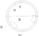
Fig. 2 is an upward view illustrating a water heater inFig. 1 . -
Fig. 3 is an enlarged drawing illustrating a position P of a water heater inFig. 1 . -
Fig. 4 is a structural schematic diagram illustrating a structure of a supporting portion of a water heater inFig. 1 . -
Fig. 5 is an upward view illustrating a supporting portion inFig. 4 . -
Fig. 6 is a left view illustrating a supporting portion inFig. 4 . -
Fig. 7 is a top view illustrating a base of a water heater inFig. 1 . - Herein, the above accompanying drawings include appended reference numbers as follows.
- 10-base; 11-groove; 12-stopping surface; 13-second positioning structure; 14-convex rib; 15-supporting surface; 20-supporting portion; 21-connection bump; 22-crimping end; 23-supporting end; 24-first positioning structure; 25-demising recession; 30-outer housing; 40-bottom plate assembly.
- It should be noted that the embodiments of the present application and features of the embodiments may be mutually combined without conflicts. The present application will be elaborated below in detail with reference to the accompanying drawings and in combination with the embodiments.
- It should be noted that unless otherwise definitely indicated, all technical and scientific terms adopted by the present application are the same meaning generally understood by ordinary skill in the art of the present application.
- In the present invention, under the premise without contrary explanation, the adopted orientation words "upper", "lower", "top", "bottom" and the like generally refer to the directions indicated by the accompanying drawings, or refer to the parts on upright, vertical or gravity directions. Similarly, in order to conveniently understand and describe, terms "inner, outer" refer to inside and outside of outlines of all parts, but the above orientation words are not adopted to limit the present invention.
- In order to solve the problem that the housing assembly in a related technology has low assembling reliability, the present invention provides a housing assembly and a water heater. The water heater is an air energy water heater, and the water heater includes a housing assembly, which is the housing assembly as follows.
- A housing assembly as shown in
Fig. 1 to Fig. 3 includes abottom plate assembly 40 and anouter housing 30. Theouter housing 30 is provided with a hooking fitting portion, and thebottom plate assembly 40 includes abase 10. A supportingportion 20 is further provided. A crimping space for positioning theouter housing 30 is formed between at least portion of the supportingportion 20 and thebase 10. The hooking fitting portion is hooked with the crimping space. - Specifically, the housing assembly is composed of two parts: the
bottom plate assembly 40 and theouter housing 30. Thebottom plate assembly 40 includes thebase 10 and the supportingportion 20. The concavo-convex crimping space is arranged between thebase 10 and the supportingportion 20. An end of theouter housing 30 of the housing assembly is provided with the hooking fitting portion, to position theouter housing 30 in the crimping space for positioning and fixing theouter housing 30, so that a firm clamping structure is formed between theouter housing 30 and thebase 10 and supportingportion 20, thus to ensure the positioning accuracy of theouter housing 30, and to improve the reliability of the housing assembly. Therefore, the supportingportion 20 is adjusted flexibility and mounted without blocking, the assembly is more easily positioned, and the assembling efficiency is higher. - Optionally, the
base 10 is provided with agroove 11 for accommodating theouter housing 30, a slot wall of thegroove 11 is used as astopping surface 12 for preventing theouter housing 30 from slipping. - Preferably, the
base 10 is provided with thegroove 11. Some or all of a hook of theouter housing 30 is accommodated in thegroove 11 to initially position theouter housing 30. Meanwhile, the side slot wall of thegroove 11 is used as the stoppingsurface 12 for stopping theouter housing 30, to form a surface contact between theouter housing 30 and thebase 10, thus to form a surface seal and enhance the sealing property therebetween, so that the water heater may perform the subsequent foaming process in a better way. Certainly, an additional sealing part is able to be added between theouter housing 30 and thebase 10 for sealing. - In an exemplary embodiment, optionally, the stopping
surface 12 is arranged in an inclined way opposite to the bottom surface of thegroove 11 to guide when installing theouter housing 30. - Specifically, the stopping
surface 12 is arranged in the inclined way opposite to the bottom surface of thegroove 11, so the stoppingsurface 12 may guide the installation of theouter housing 30, it is convenient for installers to install, thus to improve installing efficiency. - Optionally, the supporting
portion 20 is provided with aconnection bump 21 extended toward thebase 10, theconnection bump 21 is hooked with the hooking fitting portion of theouter housing 30, and a crimping space is formed between theconnection bump 21 and the slot wall of thegroove 11. - Specifically, the supporting
portion 20 is provided with theconnection bump 21 matched with thegroove 11 on thebase 10, the space between thegroove 11 and theconnection bump 21 is the crimping space. Theconnection bump 21 is hooked with theouter housing 30 so that the supportingportion 20 can be clamped with theouter housing 30, thus further ensuring the reliability of connecting theouter housing 30 with the supportingportion 20 and thebase 10. Meanwhile, there is only one degree of freedom between theouter housing 30 and thebase 10 and the supportingportion 20, so the positioning among three parts is uniquely accurate. - In an exemplary embodiment, the hooking fitting portion is a hook on an end of the
outer housing 30. The hook is hooked with theconnection bump 21, to ensure the reliability of connecting the supportingportion 20 with theouter housing 30. - Optionally, one wall surface of the
groove 11 opposite to the stoppingsurface 12 is a supportingsurface 15, and a height of the supportingsurface 15 is greater than a height of theconnection bump 21 to support the supportingportion 20. - Specifically, one surface of the
groove 11 opposite to the stoppingsurface 12 is the supportingsurface 15. The supportingsurface 15 is formed by a supporting column protruded toward the supportingportion 20 by thebase 10, and the height of the supporting column is greater than a height of theconnection bump 21, so that the supporting column may have a certain support to the supportingportion 20. Meanwhile, theconnection bump 21 is prevented from over-extending into the hook to cause instable connection. - Optionally, the supporting
portion 20 is provided with a crimpingend 22 and a supportingend 23. A bottom end of the supportingend 23 is level to a bottom end of thebase 10, and theconnection bump 21 is arranged on the crimpingend 22. - Specifically, in the present embodiment, the supporting
portion 20 is a supporting plate, the supportingportion 20 is provided with the crimpingend 22 and the supportingend 23. Theconnection bump 21 is arranged on the crimpingend 22 to match with thegroove 11 of thebase 10. A bottom end of the supportingend 23 is level to a bottom end of thebase 10, so the supportingportion 20 may share and reduce the pressure borne by thebase 10, protect the base 10 from damage caused by squeezing, and improve the whole service life of the housing assembly. - As shown in
Fig. 1 to Fig. 4 , a positive projection of the supportingportion 20 on the bottom plate assembly includes a first side projected by the supportingend 23 and a second side projected by the crimpingend 22, and the first side and the second side have the same radius of curvature. - Specifically, the supporting
portion 20 is provided with the first side and the second side. Theouter housing 30 of the water heater is generally circular, so that the supportingportion 20 is arranged into a structure with a certain radian. The first side and the second side have the same radius of curvature. Correspondingly, an installing position on thebase 11 is further arranged into a circle having the same radius of curvature, so that the supportingportion 20 is able to be installed and fixed on thebase 10. - As shown in
Fig. 4 to Fig. 7 , the supportingportion 20 is further provided with afirst positioning structure 24, and thebase 10 is further provided with asecond positioning structure 13 that is positioned and matched with thefirst positioning structure 24. - Specifically, the supporting
portion 20 is provided with thefirst positioning structure 24, thebase 10 is provided with the correspondingsecond positioning structure 13. Thefirst positioning structure 24 and thesecond positioning structure 13 may be mutually matched to form a mutual limitation, so that the supportingportion 20 may be uniquely and accurately installed on thebase 10, it is convenient for installers to install, thus to improve installing efficiency. - In an exemplary embodiment, the
first positioning structure 24 is a positioning convex column, and thesecond positioning structure 13 is a positioning hole, the positioning convex column is inserted in the positioning hole. - Specifically, the positioning convex column is protruded toward the direction of the
base 10. The positioning hole may accommodate the positioning convex column, so that the positioning convex column may be inserted in the positioning hole, and one supportingportion 20 is provided with a plurality of positioning convex columns, to further limit the installing position of the supportingportion 20 on thebase 10, and to ensure the installing accuracy. Certainly, thefirst positioning structure 24 may be arranged as a hook, which is convenient to connect when implementing the positioning effect, without connecting through additional bolts. - As shown in
Fig. 7 , thebase 10 is a cyclic structure, and an inner cyclic surface of thebase 10 is provided with aconvex rib 14, the supportingportion 20 is provided with arecess portion 25 that is adapted with theconvex rib 14 in shape. - Specifically, the
base 10 is a cyclic structure, so that thebase 10 is matched with structure of theouter housing 30, to reduce the volume of the whole water heater. The inner surface of thebase 10 is provided with theconvex rib 14, which is a protruded arc structure. Correspondingly, the supportingportion 20 is provided with therecess portion 25 to match with theconvex rib 14, so that the installer may initially limit the relative position between the supportingportion 20 and the base 10 through the structures ofconvex rib 14 and the demisingrecession 25 when installing the supportingportion 20 and thebase 10, it is convenient for installers to install, thus to improve installing efficiency. - Optionally, in the present embodiment, the housing assembly is a water tank. The outer housing of the water tank may be firmly clamped on the bottom plate assembly, thus to increase the reliability of assembling water tank.
- From the above description, it may be seen that the abovementioned embodiments of the present invention realize the following technical effects.
- Firstly, the embodiments of the present invention solve the problem that the housing assembly in the related technology has low assembling reliability.
- Secondly, the embodiments of the present invention improve the contact between the
outer housing 30 and the supportingportion 20 and form a surface contact between theouter housing 30 and thebase 10, thus to increase the sealing effect, and may foam in a better way. - Thirdly, the assembly body in the embodiments of the present invention has higher rigidity on radial direction, thus to have higher reliability and accurate location.
- Fourthly, it is more convenient to assemble and position according to the embodiments of the present invention, thus to improve the positioning accuracy and production efficiency;
- Fifthly, the embodiments of the present invention may have more elegant appearance.
- It is apparent that the described embodiments are only a part of the embodiments of the present invention, but not all. On the basis of the embodiment of the present invention, all other embodiments obtained on the premise of no creative work of those skilled in the art should fall within the protection scope of the present invention.
- It should be noted that the terms adopted here are not intended to limit the exemplary implementing manners of the present application, but only to describe the specific implementing manners. For example, as for the terms adopted here, unless otherwise indicated additionally and clearly by context, the singular form is intended to include the plural form. In addition, it should be understood that when the specification uses terms "include" and/or "contain", it should indicate existing characteristics, steps, work, parts, assemblies and/or the combination thereof.
- It should be noted that the specification and claims of the present application and terms "first", "second" and the like in the accompanying drawings are used for distinguishing similar objects rather than describing a specific sequence or a precedence order. It should be understood that the data used like this may be exchanged under appropriate circumstances, so that the embodiments of the present application described here may be implemented in an order different from that described or shown here.
- The abovementioned embodiments are only the preferable embodiments of the present invention, but not for limiting the present invention. Those skilled in the art may make variations and modifications to the present invention. Within the spirit and principle of the present invention, any made variations, equal replacements, improvements and the like shall fall in the protection scope of the present invention.
Claims (14)
- A housing assembly, comprising: a bottom plate assembly (40) and an outer housing (30), the outer housing (30) is provided with a hooking fitting portion, the bottom plate assembly (40) comprises:a base (10); anda supporting portion (20), a crimping space for positioning the outer housing (30) is formed between at least portion of the supporting portion (20) and the base (10), the hooking fitting portion is hooked with the crimping space.
- The housing assembly as claimed in claim 1, wherein the base (10) is provided with a groove (11) for accommodating the outer housing (30), a slot wall of the groove (11) is used as a stopping surface (12) for preventing the outer housing (30) from slipping.
- The housing assembly as claimed in claim 2, wherein the stopping surface (12) is arranged in an inclined way opposite to the bottom surface of the groove (11) to guide when installing the outer housing (30).
- The housing assembly as claimed in claim 2 or 3, wherein the supporting portion (20) is provided with a connection bump (21) extended toward the base (10), the connection bump (21) is hooked with the hooking fitting portion of the outer housing (30).
- The housing assembly as claimed in claim 4, wherein the crimping space is formed between the connection bump (21) and the slot wall of the groove (11).
- The housing assembly as claimed in claim 4, wherein the hooking fitting portion is a hook on an end of the outer housing (30), the hook is hooked with the connection bump (21).
- The housing assembly as claimed in claim 4, wherein a slot wall surface of the groove (11) opposite to the stopping surface (12) is a supporting surface (15), a height of the supporting surface (15) is greater than a height of the connection bump (21) to support the supporting portion (20).
- The housing assembly as claimed in claim 4, wherein the supporting portion (20) is provided with a crimping end (22) and a supporting end (23), a bottom end of the supporting end (23) is level to a bottom end of the base (10), the connection bump (21) is arranged on the crimping end (22).
- The housing assembly as claimed in claim 8, wherein a positive projection of the supporting portion (20) on the bottom plate assembly comprises a first side projected by the supporting end (23) and a second side projected by the crimping end (22), and the first side and the second side have the same radius of curvature.
- The housing assembly as claimed in claim 1, wherein the supporting portion (20) is further provided with a first positioning structure (24), and the base (10) is further provided with a second positioning structure (13) that is positioned and matched with the first positioning structure (24).
- The housing assembly as claimed in claim 10, wherein the first positioning structure (24) is a positioning convex column, the second positioning structure (13) is a positioning hole, the positioning convex column is inserted in the positioning hole.
- The housing assembly as claimed in claim 1, wherein the base (10) is a cyclic structure, and an inner cyclic surface of the base (10) is provided with a convex rib (14), the supporting portion (20) is provided with a recess portion (25) that is adapted with the convex rib (14) in shape.
- The housing assembly as claimed in claim 1, wherein the housing assembly is a water tank.
- A water heater, comprising the housing assembly as claimed in any one of claims 1 to 13.
Applications Claiming Priority (2)
| Application Number | Priority Date | Filing Date | Title |
|---|---|---|---|
| CN201711160980.1A CN108006970B (en) | 2017-11-20 | 2017-11-20 | Shell assembly and water heater |
| PCT/CN2018/101313 WO2019095761A1 (en) | 2017-11-20 | 2018-08-20 | Housing assembly and water heater |
Publications (3)
| Publication Number | Publication Date |
|---|---|
| EP3715743A1 true EP3715743A1 (en) | 2020-09-30 |
| EP3715743A4 EP3715743A4 (en) | 2021-08-18 |
| EP3715743B1 EP3715743B1 (en) | 2024-03-06 |
Family
ID=62052918
Family Applications (1)
| Application Number | Title | Priority Date | Filing Date |
|---|---|---|---|
| EP18878027.4A Active EP3715743B1 (en) | 2017-11-20 | 2018-08-20 | Housing assembly and water heater |
Country Status (5)
| Country | Link |
|---|---|
| US (1) | US11408640B2 (en) |
| EP (1) | EP3715743B1 (en) |
| CN (1) | CN108006970B (en) |
| ES (1) | ES2980535T3 (en) |
| WO (1) | WO2019095761A1 (en) |
Families Citing this family (1)
| Publication number | Priority date | Publication date | Assignee | Title |
|---|---|---|---|---|
| CN108006970B (en) * | 2017-11-20 | 2023-07-14 | 珠海格力电器股份有限公司 | Shell assembly and water heater |
Family Cites Families (24)
| Publication number | Priority date | Publication date | Assignee | Title |
|---|---|---|---|---|
| US2084481A (en) * | 1934-10-09 | 1937-06-22 | Davis William Zeller | Boiler stand |
| US2491700A (en) * | 1945-11-10 | 1949-12-20 | Zwerling Harry | Braced conduit construction |
| US2963194A (en) * | 1958-02-07 | 1960-12-06 | American Can Co | Multiple container package |
| CH559128A5 (en) * | 1972-12-04 | 1975-02-28 | Alusuisse | |
| US4351390A (en) * | 1980-02-11 | 1982-09-28 | Borg-Warner Corporation | Retaining clips for gasketed tanks on heat exchangers |
| US4452226A (en) * | 1982-09-29 | 1984-06-05 | Rheem Manufacturing Company | Water heater tank assembly |
| NL8303966A (en) * | 1983-11-17 | 1985-06-17 | Nrf Holding | RADIATOR. |
| WO2006123637A1 (en) * | 2005-05-17 | 2006-11-23 | Toyo Seikan Kaisha, Ltd. | Square can and method and device for double-seaming the same |
| EP1889673A1 (en) * | 2006-08-17 | 2008-02-20 | Corus Staal BV | Method for manufacturing a metal container |
| US7765959B2 (en) * | 2007-06-15 | 2010-08-03 | A.O. Smith Corporation | Water heater base |
| CN102374639B (en) * | 2010-08-04 | 2013-11-20 | 广东万和电气有限公司 | Insulative and heat insulative water storage electric water heater |
| US8771156B2 (en) * | 2012-02-14 | 2014-07-08 | Ever Gym Enterprises Co. Ltd. | Structure to fix inflatable and elastic motion body |
| CN202709468U (en) * | 2012-07-25 | 2013-01-30 | 珠海格力电器股份有限公司 | Shell of integral air energy water heater and integral air energy water heater |
| US20140158697A1 (en) * | 2012-12-12 | 2014-06-12 | General Electric Company | Drain pan for a water heater |
| JP2015014339A (en) * | 2013-07-05 | 2015-01-22 | 因幡電機産業株式会社 | Connecting structure of long body cover |
| JP5760052B2 (en) * | 2013-08-08 | 2015-08-05 | 日立アプライアンス株式会社 | Hot water supply system and tank unit manufacturing method |
| CN203771694U (en) * | 2013-12-05 | 2014-08-13 | 广东美的暖通设备有限公司 | Outer barrel for water tank of water heater and water heater |
| US20150233654A1 (en) * | 2014-02-14 | 2015-08-20 | Denso International America, Inc. | Tank for heat exchanger |
| JP6420577B2 (en) * | 2014-06-30 | 2018-11-07 | 東芝キヤリア株式会社 | Hot water storage water heater |
| US9541304B2 (en) * | 2014-12-10 | 2017-01-10 | Haier U.S. Appliance Solutions, Inc. | Water heater with centering thermal break support |
| CN204757382U (en) * | 2015-07-07 | 2015-11-11 | 珠海格力电器股份有限公司 | top cover, water tank and water heater |
| CN107975944B (en) * | 2017-11-20 | 2024-04-16 | 珠海格力电器股份有限公司 | Base mechanism, shell assembly and water heater |
| CN108006970B (en) * | 2017-11-20 | 2023-07-14 | 珠海格力电器股份有限公司 | Shell assembly and water heater |
| CN207501454U (en) * | 2017-11-20 | 2018-06-15 | 珠海格力电器股份有限公司 | Shell assembly and water heater |
-
2017
- 2017-11-20 CN CN201711160980.1A patent/CN108006970B/en active Active
-
2018
- 2018-08-20 EP EP18878027.4A patent/EP3715743B1/en active Active
- 2018-08-20 ES ES18878027T patent/ES2980535T3/en active Active
- 2018-08-20 US US16/763,445 patent/US11408640B2/en active Active
- 2018-08-20 WO PCT/CN2018/101313 patent/WO2019095761A1/en not_active Ceased
Also Published As
| Publication number | Publication date |
|---|---|
| ES2980535T3 (en) | 2024-10-01 |
| CN108006970A (en) | 2018-05-08 |
| EP3715743A4 (en) | 2021-08-18 |
| EP3715743B1 (en) | 2024-03-06 |
| CN108006970B (en) | 2023-07-14 |
| WO2019095761A1 (en) | 2019-05-23 |
| US11408640B2 (en) | 2022-08-09 |
| US20200318856A1 (en) | 2020-10-08 |
Similar Documents
| Publication | Publication Date | Title |
|---|---|---|
| US11493187B2 (en) | Recessed light-emitting diode lighting fixture | |
| US10174916B2 (en) | Rotatable junction box assembly | |
| WO2015060396A1 (en) | Hole plug | |
| EP3190308B1 (en) | Air spring device | |
| US11408640B2 (en) | Housing assembly and water heater | |
| US12234942B2 (en) | Stand for electronic device and electronic device assembly | |
| US20250028133A1 (en) | Positioning fixture for fixing end face structure of optical fiber splice closure | |
| WO2019095760A1 (en) | Base plate assembly, water tank and water heater | |
| CN107327976B (en) | Electric control assembly, air conditioner outdoor unit and air conditioner | |
| US7530834B2 (en) | Cover assembly with electronic connectors | |
| JP3196772U (en) | Probe connector | |
| CN219760773U (en) | Vibration-proof ring and motor assembly | |
| CN219739090U (en) | Battery top cap subassembly and battery cell | |
| CN203857663U (en) | Wall-mounted air conditioner and base thereof | |
| CN207501454U (en) | Shell assembly and water heater | |
| CN210320522U (en) | Installing support, domestic appliance's installation component and humidifier | |
| US20260002665A1 (en) | Lamp | |
| CN220417164U (en) | Rigid support, ceiling device and ceiling lamp | |
| CN113669605B (en) | Wall-mounted device | |
| CN104654180A (en) | Lamp and over-line sealing structure thereof | |
| CN221932125U (en) | A surgical robot | |
| CN219974820U (en) | Compressor base connection structure | |
| CN216202589U (en) | Rubber ring of light source module and light source module | |
| CN219979776U (en) | Pole mounting and fixing structure and lithium battery | |
| CN220404457U (en) | Sealing assembly of ultraviolet lamp and ultraviolet lamp formed by sealing assembly |
Legal Events
| Date | Code | Title | Description |
|---|---|---|---|
| STAA | Information on the status of an ep patent application or granted ep patent |
Free format text: STATUS: THE INTERNATIONAL PUBLICATION HAS BEEN MADE |
|
| PUAI | Public reference made under article 153(3) epc to a published international application that has entered the european phase |
Free format text: ORIGINAL CODE: 0009012 |
|
| STAA | Information on the status of an ep patent application or granted ep patent |
Free format text: STATUS: REQUEST FOR EXAMINATION WAS MADE |
|
| 17P | Request for examination filed |
Effective date: 20200108 |
|
| AK | Designated contracting states |
Kind code of ref document: A1 Designated state(s): AL AT BE BG CH CY CZ DE DK EE ES FI FR GB GR HR HU IE IS IT LI LT LU LV MC MK MT NL NO PL PT RO RS SE SI SK SM TR |
|
| AX | Request for extension of the european patent |
Extension state: BA ME |
|
| DAV | Request for validation of the european patent (deleted) | ||
| DAX | Request for extension of the european patent (deleted) | ||
| A4 | Supplementary search report drawn up and despatched |
Effective date: 20210715 |
|
| RIC1 | Information provided on ipc code assigned before grant |
Ipc: F24H 9/00 20060101AFI20210709BHEP Ipc: F24H 9/02 20060101ALI20210709BHEP Ipc: F24H 7/00 20060101ALI20210709BHEP Ipc: F24H 9/06 20060101ALI20210709BHEP Ipc: F24H 9/14 20060101ALI20210709BHEP |
|
| P01 | Opt-out of the competence of the unified patent court (upc) registered |
Effective date: 20230530 |
|
| GRAP | Despatch of communication of intention to grant a patent |
Free format text: ORIGINAL CODE: EPIDOSNIGR1 |
|
| STAA | Information on the status of an ep patent application or granted ep patent |
Free format text: STATUS: GRANT OF PATENT IS INTENDED |
|
| INTG | Intention to grant announced |
Effective date: 20231114 |
|
| GRAS | Grant fee paid |
Free format text: ORIGINAL CODE: EPIDOSNIGR3 |
|
| GRAA | (expected) grant |
Free format text: ORIGINAL CODE: 0009210 |
|
| STAA | Information on the status of an ep patent application or granted ep patent |
Free format text: STATUS: THE PATENT HAS BEEN GRANTED |
|
| AK | Designated contracting states |
Kind code of ref document: B1 Designated state(s): AL AT BE BG CH CY CZ DE DK EE ES FI FR GB GR HR HU IE IS IT LI LT LU LV MC MK MT NL NO PL PT RO RS SE SI SK SM TR |
|
| REG | Reference to a national code |
Ref country code: GB Ref legal event code: FG4D |
|
| REG | Reference to a national code |
Ref country code: CH Ref legal event code: EP |
|
| REG | Reference to a national code |
Ref country code: IE Ref legal event code: FG4D |
|
| REG | Reference to a national code |
Ref country code: DE Ref legal event code: R096 Ref document number: 602018066380 Country of ref document: DE |
|
| REG | Reference to a national code |
Ref country code: LT Ref legal event code: MG9D |
|
| PG25 | Lapsed in a contracting state [announced via postgrant information from national office to epo] |
Ref country code: LT Free format text: LAPSE BECAUSE OF FAILURE TO SUBMIT A TRANSLATION OF THE DESCRIPTION OR TO PAY THE FEE WITHIN THE PRESCRIBED TIME-LIMIT Effective date: 20240306 |
|
| REG | Reference to a national code |
Ref country code: NL Ref legal event code: MP Effective date: 20240306 |
|
| PG25 | Lapsed in a contracting state [announced via postgrant information from national office to epo] |
Ref country code: GR Free format text: LAPSE BECAUSE OF FAILURE TO SUBMIT A TRANSLATION OF THE DESCRIPTION OR TO PAY THE FEE WITHIN THE PRESCRIBED TIME-LIMIT Effective date: 20240607 |
|
| PG25 | Lapsed in a contracting state [announced via postgrant information from national office to epo] |
Ref country code: RS Free format text: LAPSE BECAUSE OF FAILURE TO SUBMIT A TRANSLATION OF THE DESCRIPTION OR TO PAY THE FEE WITHIN THE PRESCRIBED TIME-LIMIT Effective date: 20240606 Ref country code: HR Free format text: LAPSE BECAUSE OF FAILURE TO SUBMIT A TRANSLATION OF THE DESCRIPTION OR TO PAY THE FEE WITHIN THE PRESCRIBED TIME-LIMIT Effective date: 20240306 |
|
| PG25 | Lapsed in a contracting state [announced via postgrant information from national office to epo] |
Ref country code: RS Free format text: LAPSE BECAUSE OF FAILURE TO SUBMIT A TRANSLATION OF THE DESCRIPTION OR TO PAY THE FEE WITHIN THE PRESCRIBED TIME-LIMIT Effective date: 20240606 Ref country code: NO Free format text: LAPSE BECAUSE OF FAILURE TO SUBMIT A TRANSLATION OF THE DESCRIPTION OR TO PAY THE FEE WITHIN THE PRESCRIBED TIME-LIMIT Effective date: 20240606 Ref country code: LT Free format text: LAPSE BECAUSE OF FAILURE TO SUBMIT A TRANSLATION OF THE DESCRIPTION OR TO PAY THE FEE WITHIN THE PRESCRIBED TIME-LIMIT Effective date: 20240306 Ref country code: HR Free format text: LAPSE BECAUSE OF FAILURE TO SUBMIT A TRANSLATION OF THE DESCRIPTION OR TO PAY THE FEE WITHIN THE PRESCRIBED TIME-LIMIT Effective date: 20240306 Ref country code: GR Free format text: LAPSE BECAUSE OF FAILURE TO SUBMIT A TRANSLATION OF THE DESCRIPTION OR TO PAY THE FEE WITHIN THE PRESCRIBED TIME-LIMIT Effective date: 20240607 Ref country code: FI Free format text: LAPSE BECAUSE OF FAILURE TO SUBMIT A TRANSLATION OF THE DESCRIPTION OR TO PAY THE FEE WITHIN THE PRESCRIBED TIME-LIMIT Effective date: 20240306 Ref country code: BG Free format text: LAPSE BECAUSE OF FAILURE TO SUBMIT A TRANSLATION OF THE DESCRIPTION OR TO PAY THE FEE WITHIN THE PRESCRIBED TIME-LIMIT Effective date: 20240306 |
|
| REG | Reference to a national code |
Ref country code: AT Ref legal event code: MK05 Ref document number: 1663878 Country of ref document: AT Kind code of ref document: T Effective date: 20240306 |
|
| PG25 | Lapsed in a contracting state [announced via postgrant information from national office to epo] |
Ref country code: SE Free format text: LAPSE BECAUSE OF FAILURE TO SUBMIT A TRANSLATION OF THE DESCRIPTION OR TO PAY THE FEE WITHIN THE PRESCRIBED TIME-LIMIT Effective date: 20240306 Ref country code: LV Free format text: LAPSE BECAUSE OF FAILURE TO SUBMIT A TRANSLATION OF THE DESCRIPTION OR TO PAY THE FEE WITHIN THE PRESCRIBED TIME-LIMIT Effective date: 20240306 |
|
| PG25 | Lapsed in a contracting state [announced via postgrant information from national office to epo] |
Ref country code: NL Free format text: LAPSE BECAUSE OF FAILURE TO SUBMIT A TRANSLATION OF THE DESCRIPTION OR TO PAY THE FEE WITHIN THE PRESCRIBED TIME-LIMIT Effective date: 20240306 |
|
| PG25 | Lapsed in a contracting state [announced via postgrant information from national office to epo] |
Ref country code: NL Free format text: LAPSE BECAUSE OF FAILURE TO SUBMIT A TRANSLATION OF THE DESCRIPTION OR TO PAY THE FEE WITHIN THE PRESCRIBED TIME-LIMIT Effective date: 20240306 |
|
| REG | Reference to a national code |
Ref country code: ES Ref legal event code: FG2A Ref document number: 2980535 Country of ref document: ES Kind code of ref document: T3 Effective date: 20241001 |
|
| PG25 | Lapsed in a contracting state [announced via postgrant information from national office to epo] |
Ref country code: IS Free format text: LAPSE BECAUSE OF FAILURE TO SUBMIT A TRANSLATION OF THE DESCRIPTION OR TO PAY THE FEE WITHIN THE PRESCRIBED TIME-LIMIT Effective date: 20240706 |
|
| PG25 | Lapsed in a contracting state [announced via postgrant information from national office to epo] |
Ref country code: SM Free format text: LAPSE BECAUSE OF FAILURE TO SUBMIT A TRANSLATION OF THE DESCRIPTION OR TO PAY THE FEE WITHIN THE PRESCRIBED TIME-LIMIT Effective date: 20240306 Ref country code: PT Free format text: LAPSE BECAUSE OF FAILURE TO SUBMIT A TRANSLATION OF THE DESCRIPTION OR TO PAY THE FEE WITHIN THE PRESCRIBED TIME-LIMIT Effective date: 20240708 |
|
| PG25 | Lapsed in a contracting state [announced via postgrant information from national office to epo] |
Ref country code: EE Free format text: LAPSE BECAUSE OF FAILURE TO SUBMIT A TRANSLATION OF THE DESCRIPTION OR TO PAY THE FEE WITHIN THE PRESCRIBED TIME-LIMIT Effective date: 20240306 Ref country code: CZ Free format text: LAPSE BECAUSE OF FAILURE TO SUBMIT A TRANSLATION OF THE DESCRIPTION OR TO PAY THE FEE WITHIN THE PRESCRIBED TIME-LIMIT Effective date: 20240306 |
|
| PG25 | Lapsed in a contracting state [announced via postgrant information from national office to epo] |
Ref country code: AT Free format text: LAPSE BECAUSE OF FAILURE TO SUBMIT A TRANSLATION OF THE DESCRIPTION OR TO PAY THE FEE WITHIN THE PRESCRIBED TIME-LIMIT Effective date: 20240306 |
|
| PG25 | Lapsed in a contracting state [announced via postgrant information from national office to epo] |
Ref country code: PL Free format text: LAPSE BECAUSE OF FAILURE TO SUBMIT A TRANSLATION OF THE DESCRIPTION OR TO PAY THE FEE WITHIN THE PRESCRIBED TIME-LIMIT Effective date: 20240306 |
|
| PG25 | Lapsed in a contracting state [announced via postgrant information from national office to epo] |
Ref country code: SK Free format text: LAPSE BECAUSE OF FAILURE TO SUBMIT A TRANSLATION OF THE DESCRIPTION OR TO PAY THE FEE WITHIN THE PRESCRIBED TIME-LIMIT Effective date: 20240306 |
|
| PG25 | Lapsed in a contracting state [announced via postgrant information from national office to epo] |
Ref country code: SM Free format text: LAPSE BECAUSE OF FAILURE TO SUBMIT A TRANSLATION OF THE DESCRIPTION OR TO PAY THE FEE WITHIN THE PRESCRIBED TIME-LIMIT Effective date: 20240306 Ref country code: SK Free format text: LAPSE BECAUSE OF FAILURE TO SUBMIT A TRANSLATION OF THE DESCRIPTION OR TO PAY THE FEE WITHIN THE PRESCRIBED TIME-LIMIT Effective date: 20240306 Ref country code: RO Free format text: LAPSE BECAUSE OF FAILURE TO SUBMIT A TRANSLATION OF THE DESCRIPTION OR TO PAY THE FEE WITHIN THE PRESCRIBED TIME-LIMIT Effective date: 20240306 Ref country code: PT Free format text: LAPSE BECAUSE OF FAILURE TO SUBMIT A TRANSLATION OF THE DESCRIPTION OR TO PAY THE FEE WITHIN THE PRESCRIBED TIME-LIMIT Effective date: 20240708 Ref country code: PL Free format text: LAPSE BECAUSE OF FAILURE TO SUBMIT A TRANSLATION OF THE DESCRIPTION OR TO PAY THE FEE WITHIN THE PRESCRIBED TIME-LIMIT Effective date: 20240306 Ref country code: IS Free format text: LAPSE BECAUSE OF FAILURE TO SUBMIT A TRANSLATION OF THE DESCRIPTION OR TO PAY THE FEE WITHIN THE PRESCRIBED TIME-LIMIT Effective date: 20240706 Ref country code: EE Free format text: LAPSE BECAUSE OF FAILURE TO SUBMIT A TRANSLATION OF THE DESCRIPTION OR TO PAY THE FEE WITHIN THE PRESCRIBED TIME-LIMIT Effective date: 20240306 Ref country code: CZ Free format text: LAPSE BECAUSE OF FAILURE TO SUBMIT A TRANSLATION OF THE DESCRIPTION OR TO PAY THE FEE WITHIN THE PRESCRIBED TIME-LIMIT Effective date: 20240306 Ref country code: AT Free format text: LAPSE BECAUSE OF FAILURE TO SUBMIT A TRANSLATION OF THE DESCRIPTION OR TO PAY THE FEE WITHIN THE PRESCRIBED TIME-LIMIT Effective date: 20240306 |
|
| REG | Reference to a national code |
Ref country code: DE Ref legal event code: R097 Ref document number: 602018066380 Country of ref document: DE |
|
| PLBE | No opposition filed within time limit |
Free format text: ORIGINAL CODE: 0009261 |
|
| STAA | Information on the status of an ep patent application or granted ep patent |
Free format text: STATUS: NO OPPOSITION FILED WITHIN TIME LIMIT |
|
| PG25 | Lapsed in a contracting state [announced via postgrant information from national office to epo] |
Ref country code: DK Free format text: LAPSE BECAUSE OF FAILURE TO SUBMIT A TRANSLATION OF THE DESCRIPTION OR TO PAY THE FEE WITHIN THE PRESCRIBED TIME-LIMIT Effective date: 20240306 |
|
| PG25 | Lapsed in a contracting state [announced via postgrant information from national office to epo] |
Ref country code: DK Free format text: LAPSE BECAUSE OF FAILURE TO SUBMIT A TRANSLATION OF THE DESCRIPTION OR TO PAY THE FEE WITHIN THE PRESCRIBED TIME-LIMIT Effective date: 20240306 |
|
| 26N | No opposition filed |
Effective date: 20241209 |
|
| REG | Reference to a national code |
Ref country code: CH Ref legal event code: PL |
|
| PG25 | Lapsed in a contracting state [announced via postgrant information from national office to epo] |
Ref country code: LU Free format text: LAPSE BECAUSE OF NON-PAYMENT OF DUE FEES Effective date: 20240820 |
|
| PG25 | Lapsed in a contracting state [announced via postgrant information from national office to epo] |
Ref country code: MC Free format text: LAPSE BECAUSE OF FAILURE TO SUBMIT A TRANSLATION OF THE DESCRIPTION OR TO PAY THE FEE WITHIN THE PRESCRIBED TIME-LIMIT Effective date: 20240306 Ref country code: SI Free format text: LAPSE BECAUSE OF FAILURE TO SUBMIT A TRANSLATION OF THE DESCRIPTION OR TO PAY THE FEE WITHIN THE PRESCRIBED TIME-LIMIT Effective date: 20240306 Ref country code: CH Free format text: LAPSE BECAUSE OF NON-PAYMENT OF DUE FEES Effective date: 20240831 |
|
| REG | Reference to a national code |
Ref country code: BE Ref legal event code: MM Effective date: 20240831 |
|
| PG25 | Lapsed in a contracting state [announced via postgrant information from national office to epo] |
Ref country code: BE Free format text: LAPSE BECAUSE OF NON-PAYMENT OF DUE FEES Effective date: 20240831 |
|
| PG25 | Lapsed in a contracting state [announced via postgrant information from national office to epo] |
Ref country code: IE Free format text: LAPSE BECAUSE OF NON-PAYMENT OF DUE FEES Effective date: 20240820 |
|
| PGFP | Annual fee paid to national office [announced via postgrant information from national office to epo] |
Ref country code: ES Payment date: 20250917 Year of fee payment: 8 |
|
| PGFP | Annual fee paid to national office [announced via postgrant information from national office to epo] |
Ref country code: DE Payment date: 20250819 Year of fee payment: 8 |
|
| PGFP | Annual fee paid to national office [announced via postgrant information from national office to epo] |
Ref country code: IT Payment date: 20250829 Year of fee payment: 8 |
|
| PGFP | Annual fee paid to national office [announced via postgrant information from national office to epo] |
Ref country code: GB Payment date: 20250709 Year of fee payment: 8 |
|
| PGFP | Annual fee paid to national office [announced via postgrant information from national office to epo] |
Ref country code: FR Payment date: 20250709 Year of fee payment: 8 |
|
| PG25 | Lapsed in a contracting state [announced via postgrant information from national office to epo] |
Ref country code: CY Free format text: LAPSE BECAUSE OF FAILURE TO SUBMIT A TRANSLATION OF THE DESCRIPTION OR TO PAY THE FEE WITHIN THE PRESCRIBED TIME-LIMIT; INVALID AB INITIO Effective date: 20180820 |
|
| PG25 | Lapsed in a contracting state [announced via postgrant information from national office to epo] |
Ref country code: HU Free format text: LAPSE BECAUSE OF FAILURE TO SUBMIT A TRANSLATION OF THE DESCRIPTION OR TO PAY THE FEE WITHIN THE PRESCRIBED TIME-LIMIT; INVALID AB INITIO Effective date: 20180820 |