EP3715741A1 - Indoor unit for air conditioner - Google Patents
Indoor unit for air conditioner Download PDFInfo
- Publication number
- EP3715741A1 EP3715741A1 EP18877770.0A EP18877770A EP3715741A1 EP 3715741 A1 EP3715741 A1 EP 3715741A1 EP 18877770 A EP18877770 A EP 18877770A EP 3715741 A1 EP3715741 A1 EP 3715741A1
- Authority
- EP
- European Patent Office
- Prior art keywords
- indoor unit
- disposed
- shaped pipe
- panel
- coupling member
- Prior art date
- Legal status (The legal status is an assumption and is not a legal conclusion. Google has not performed a legal analysis and makes no representation as to the accuracy of the status listed.)
- Withdrawn
Links
- 230000008878 coupling Effects 0.000 claims abstract description 56
- 238000010168 coupling process Methods 0.000 claims abstract description 56
- 238000005859 coupling reaction Methods 0.000 claims abstract description 56
- 239000003507 refrigerant Substances 0.000 claims abstract description 30
- 239000002184 metal Substances 0.000 description 9
- 230000000694 effects Effects 0.000 description 7
- 230000004048 modification Effects 0.000 description 3
- 238000012986 modification Methods 0.000 description 3
- 239000004820 Pressure-sensitive adhesive Substances 0.000 description 2
- 239000000853 adhesive Substances 0.000 description 2
- 230000001070 adhesive effect Effects 0.000 description 2
- 239000000969 carrier Substances 0.000 description 2
- 238000005192 partition Methods 0.000 description 2
- 239000000428 dust Substances 0.000 description 1
- 239000011347 resin Substances 0.000 description 1
- 229920005989 resin Polymers 0.000 description 1
Images






Classifications
-
- F—MECHANICAL ENGINEERING; LIGHTING; HEATING; WEAPONS; BLASTING
- F24—HEATING; RANGES; VENTILATING
- F24F—AIR-CONDITIONING; AIR-HUMIDIFICATION; VENTILATION; USE OF AIR CURRENTS FOR SCREENING
- F24F1/00—Room units for air-conditioning, e.g. separate or self-contained units or units receiving primary air from a central station
- F24F1/0007—Indoor units, e.g. fan coil units
- F24F1/0011—Indoor units, e.g. fan coil units characterised by air outlets
-
- F—MECHANICAL ENGINEERING; LIGHTING; HEATING; WEAPONS; BLASTING
- F24—HEATING; RANGES; VENTILATING
- F24F—AIR-CONDITIONING; AIR-HUMIDIFICATION; VENTILATION; USE OF AIR CURRENTS FOR SCREENING
- F24F1/00—Room units for air-conditioning, e.g. separate or self-contained units or units receiving primary air from a central station
- F24F1/0007—Indoor units, e.g. fan coil units
- F24F1/0043—Indoor units, e.g. fan coil units characterised by mounting arrangements
- F24F1/0057—Indoor units, e.g. fan coil units characterised by mounting arrangements mounted in or on a wall
-
- F—MECHANICAL ENGINEERING; LIGHTING; HEATING; WEAPONS; BLASTING
- F24—HEATING; RANGES; VENTILATING
- F24F—AIR-CONDITIONING; AIR-HUMIDIFICATION; VENTILATION; USE OF AIR CURRENTS FOR SCREENING
- F24F1/00—Room units for air-conditioning, e.g. separate or self-contained units or units receiving primary air from a central station
- F24F1/0007—Indoor units, e.g. fan coil units
- F24F1/0059—Indoor units, e.g. fan coil units characterised by heat exchangers
- F24F1/0063—Indoor units, e.g. fan coil units characterised by heat exchangers by the mounting or arrangement of the heat exchangers
-
- F—MECHANICAL ENGINEERING; LIGHTING; HEATING; WEAPONS; BLASTING
- F24—HEATING; RANGES; VENTILATING
- F24F—AIR-CONDITIONING; AIR-HUMIDIFICATION; VENTILATION; USE OF AIR CURRENTS FOR SCREENING
- F24F1/00—Room units for air-conditioning, e.g. separate or self-contained units or units receiving primary air from a central station
- F24F1/0007—Indoor units, e.g. fan coil units
- F24F1/0068—Indoor units, e.g. fan coil units characterised by the arrangement of refrigerant piping outside the heat exchanger within the unit casing
-
- F—MECHANICAL ENGINEERING; LIGHTING; HEATING; WEAPONS; BLASTING
- F24—HEATING; RANGES; VENTILATING
- F24F—AIR-CONDITIONING; AIR-HUMIDIFICATION; VENTILATION; USE OF AIR CURRENTS FOR SCREENING
- F24F13/00—Details common to, or for air-conditioning, air-humidification, ventilation or use of air currents for screening
- F24F13/20—Casings or covers
Definitions
- An indoor unit of an air conditioner with a moving front panel An indoor unit of an air conditioner with a moving front panel.
- Examples of a conventional indoor unit of an air conditioner include, as described in Patent Literature 1 ( JP 2000-234760 A ), an indoor unit in which a front panel of a casing moves in a vertical direction and includes a panel drive unit that drives the front panel.
- An indoor unit of an air conditioner includes a casing that has a front panel at a front of the casing and a back surface on a rear of the casing, the back surface being fixed to a wall, a heat exchanger that is housed in the casing and has a U-shaped pipe that returns refrigerant flowing in a longitudinal direction, a panel drive unit that is housed in the casing and generates a driving force that moves the front panel by a movement of the panel drive unit itself, and a coupling member that is disposed behind the front panel, couples the front panel and the panel drive unit, and transmits the driving force from the panel drive unit to the front panel, in which the coupling member is disposed in front of the U-shaped pipe so as to at least partially overlap the U-shaped pipe as viewed from a front.
- the coupling member is disposed so as to overlap the U-shaped pipe as viewed from the front, and a space in front of the U-shaped pipe that hardly contributes to heat exchange performance is effectively utilized. As a result, a reduction of the heat exchange performance of the indoor unit can be suppressed.
- An indoor unit of an air conditioner is the indoor unit according to the first aspect, in which the U-shaped pipe includes a first U-shaped pipe disposed at a first end in the longitudinal direction, and a second U-shaped pipe disposed at a second end in the longitudinal direction, and the coupling member includes a first coupling member disposed in front of the first U-shaped pipe so as to at least partially overlap the first U-shaped pipe as viewed from the front, and a second coupling member disposed in front of the second U-shaped pipe so as to at least partially overlap the second U-shaped pipe as viewed from the front.
- two spaces in front of the first U-shaped pipe and the second U-shaped pipe are effectively utilized. This can enhance the effect of suppressing the reduction of the heat exchange performance of the indoor unit.
- An indoor unit of an air conditioner is the indoor unit of the first or second aspect, in which the panel drive unit includes at least one gear disposed in front of a refrigerant pipe extending from the heat exchanger, and the coupling member rotates in accordance with a movement of the gear.
- This configuration allows a space in front of the refrigerant pipe to be effectively utilized.
- the compactness of the indoor unit 1 can be achieved.
- An indoor unit of an air conditioner according to a fourth aspect is the indoor unit according to the third aspect, in which the gear is disposed at a position where at least a part of the gear does not overlap the heat exchanger as viewed from a side. This configuration makes it easy to design an arrangement of the panel drive unit and the refrigerant pipe.
- An indoor unit of an air conditioner according to a fifth aspect is the indoor unit according to the third or fourth aspect, in which the gear configures a planetary gear mechanism.
- An indoor unit of an air conditioner is the indoor unit according to any one of the third to fifth aspects, further including an electric component box that is housed in the casing and electrically connected to the panel drive unit, in which the gear has a center of the longitudinal direction of the gear, the center being disposed between a center of the longitudinal direction of the heat exchanger and a center of the longitudinal direction of the electric component box.
- This configuration can make the indoor unit more compact in the longitudinal direction than a configuration in which the center of the gear is disposed on the opposite side of the heat exchanger with the electric component box interposed therebetween.
- An indoor unit of an air conditioner of a seventh aspect is the indoor unit of any one of the first to sixth aspects, in which the coupling member is a component member of a crank mechanism that converts a rotational movement of the panel drive unit into a reciprocating movement of the front panel that reciprocates between an upper front position and a rear lower position.
- the coupling member is a component member of a crank mechanism that converts a rotational movement of the panel drive unit into a reciprocating movement of the front panel that reciprocates between an upper front position and a rear lower position.
- an indoor unit 1 of an air conditioner includes a casing 10, a heat exchanger 20, a coupling member 40, and a panel drive unit 50.
- the heat exchanger 20 and the panel drive unit 50 are housed in the casing 10.
- the indoor unit 1 is wall-mounted, and a back surface 10b on a rear of the indoor unit 1 is fixed to a wall.
- FIGS. 1 and 2 show the indoor unit 1 that is stopped.
- FIG. 3 shows the indoor unit 1 preparing for operation.
- FIG. 4 shows the indoor unit 1 in operation.
- FIGS. 1 and 2 are cross-sectional views of the indoor unit 1 cut at different positions along a plane extending in a front-and-rear direction and in an upper-and-lower direction.
- the casing 10 has a movable front panel 11 and a fixed upper panel 12 at a front of the casing.
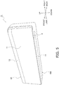
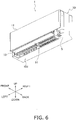
- FIGS. 5 and 6 respectively show an appearance of the indoor unit 1 that is stopped and an appearance of the indoor unit 1 in operation.
- the front panel 11 is closed, or in other words, the front panel 11 is in a rear lower position.
- the front panel 11 is opened, or in other words, the front panel 11 is in an upper front position.
- FIG. 7 shows a configuration around the coupling member 40 with the front panel 11 removed from the indoor unit 1.
- the coupling member 40 is disposed behind the front panel 11.
- FIG. 8 shows the heat exchanger 20 and the panel drive unit 50 that are attached to a bottom frame 16.
- the heat exchanger 20 has a U-shaped pipe 25 that returns refrigerant flowing in a longitudinal direction (left and right direction) of the indoor unit 1 at both left and right ends of the heat exchanger 20.
- FIG. 9 shows the coupling member 40 in addition to the configuration shown in FIG. 8 . As can be seen by comparing FIGS. 8 and 9 , the coupling member 40 is disposed in front of the U-shaped pipe 25 so as to at least partially overlap the U-shaped pipe 25 as viewed from the front.
- the panel drive unit 50 includes a motor 51 and a gear 52 (see FIG. 11 ).
- the motor 51 generates a driving force that moves the front panel 11 by a rotational movement of the motor itself.
- the rotational movement of the motor 51 is transmitted to the coupling member 40 through the gear 52 as the driving force for movement.
- the front panel 11 is disposed on substantially the same plane as the upper panel 12.
- the front panel 11 that is in the rear lower position when the indoor unit 1 is stopped moves to the upper front position shown in FIG. 3 when the indoor unit 1 is in preparation for operation, whereby the upper panel 12 and the front panel 11 overlap each other as viewed from the front.
- a first horizontal flap 13 that configures a bottom surface 10d of the casing 10 when the indoor unit 1 is stopped rotates and moves to an upper front position as shown in FIG. 4 .
- the casing 10 has a rectangular parallelepiped shape that is longer in the left and right direction.
- the front panel 11 is closed, or in other words, the front panel 11 is in the rear lower position.
- the front panel 11 is opened, or in other words, the front panel 11 is in the upper front position.
- a suction port 4 includes not only an upper suction port 4A (see FIG. 7 ) formed on a top surface 10c of the casing 10, but also a front suction port 4B (see FIG. 3 ) that is opened by the movement of the front panel 11 to the upper front position when the indoor unit 1 is in operation.
- the casing 10 houses a filter 15 disposed between the heat exchanger 20 and the suction port 4. Dust is removed, by the filter 15, from indoor air that enters the suction port 4 and passes through the filter 15. The indoor air that has passed through the filter 15 flows into the heat exchanger 20.
- the casing 10 houses a fan 90 on a downstream side of the heat exchanger 20.
- the fan 90 is, for example, a cross-flow fan that extends to left and right along the longitudinal direction of the heat exchanger 20.
- a blow-out passage 17 is formed on the downstream side of the fan 90.
- FIG. 1 and other drawings a plurality of blades disposed on a circumference of a partition plate is not shown because the cross-flow fan is cut at the partition plate of the cross-flow fan.
- a plurality of vertical flaps 19 arranged in the longitudinal direction (left and right direction) is attached to the blow-out passage 17.
- the first horizontal flap 13 and a second horizontal flap 14 are attached downstream of the vertical flap 19.
- An outlet of the blow-out passage 17 is a blow-out port 5.
- the blow-out passage 17 and the bottom surface 10d of the casing 10 are configured by the bottom frame 16 made of resin.
- FIG. 8 shows the heat exchanger 20 and the electric component box 70 that are disposed in the casing 10.
- the electric component box 70 is disposed on the right of the heat exchanger 20, or in other words, closer to the right in the casing 10.
- the electric component box 70 incorporates a control unit (not shown) that controls the motor 51, the fan 90, and the like.
- the heat exchanger 20 can be divided into a front heat exchange section 21 and a rear heat exchange section 22. An upper part of the front heat exchange section 21 and an upper part of the rear heat exchange section 22 are connected to each other. Due to such a structure of the heat exchanger 20, the heat exchanger 20 has a ⁇ shape as viewed from a side.
- the heat exchanger 20 includes a plurality of metal heat transfer fins 23 disposed side by side in the longitudinal direction, a plurality of metal heat transfer tubes 24 that extends in the longitudinal direction through the plurality of heat transfer fins 23, the metal U-shaped pipe 25 that connects two of the heat transfer tubes in order to return and flow the refrigerant at an end of the heat exchanger 20.
- the U-shaped pipe 25 includes a first U-shaped pipe 25a disposed on the right as viewed from the front and a second U-shaped pipe 25b disposed on the left as viewed from the front.
- a plurality of refrigerant pipes 26 is connected to the heat exchanger 20. The refrigerant flows into the heat exchanger 20 from the outside through the refrigerant pipes 26, and the refrigerant flows from the heat exchanger 20 to the outside through the refrigerant pipes 26.
- the coupling member 40 includes a first upper crank 31, a first lower crank 32, a first link 33, a second upper crank 34, a second lower crank 35, and a second link 36.
- the first upper crank 31, the first lower crank 32, and the first link 33 are a first coupling member 41, and configure a first parallel crank mechanism.
- the second upper crank 34, the second lower crank 35, and the second link 36 are a second coupling member 42 and configure a second parallel crank mechanism.
- the first upper crank 31, the first lower crank 32, and the first link 33 that configure the first parallel crank mechanism of the coupling member 40 do not overlap the heat transfer fins 23 of the heat exchanger 20 at all as viewed from the front.
- the first upper crank 31, the first lower crank 32, and the first link 33 are in a range in which the first U-shaped pipe 25a is disposed, in the longitudinal direction as viewed from the front.
- the second upper crank 34, the second lower crank 35, and the second link 36 that configure the second parallel crank mechanism partially overlap the heat transfer fins 23 of the heat exchanger 20 as viewed from the front.
- the second upper crank 34, the second lower crank 35, and the second link 36 also partially overlap the second U-shaped pipe 25b as viewed from the front.
- the first upper crank 31, the first lower crank 32, and the first link 33 that configure the first coupling member 41 of the coupling member 40 do not disturb a flow of the indoor air flowing to the heat transfer fins 23 of the heat exchanger 20.
- the second upper crank 34, the second lower crank 35 and the second link 36 that configure the second coupling member 42 partially overlap the heat transfer fins 23 but protrude toward the second U-shaped pipe 25b as viewed from the front. This suppresses disturbing the flow of the indoor air flowing to the heat transfer fins 23 at a left end of the heat exchanger 20.
- most of the second upper crank 34 and the second lower crank 35 are away from the heat transfer fins 23. Sufficient indoor air flows to the heat transfer fins 23 on the left end of the heat exchanger 20 similarly to the other parts.
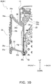
- FIG. 10 mainly shows the second parallel crank mechanism.
- the second upper crank 34 of the second parallel crank mechanism is bent in an L shape as viewed from the side.
- a joint portion 34a is formed with a square coupling hole 34b into which a metal shaft 100 (see FIG. 8 ) having a square cross section is fitted.
- a metal shaft 100 see FIG. 8
- An inner arm 34c extends from the joint portion 34a.
- the inner arm 34c has a relatively short arm length so as not to collide with the upper panel 12 of the casing 10, the heat exchanger 20, and the like in a rotation range of the inner arm 34c.
- a direction in which a panel side arm 34d extends outward from the inner arm 34c is bent upward by about 90 degrees with respect to a direction in which the inner arm 34c extends as viewed from the side.
- the panel side arm 34d has an arm length longer than the arm length of the inner arm 34c in order to increase a moving distance of the front panel 11.
- a shaft 34e is provided at a panel side tip of the panel side arm 34d.
- the shaft 34e of the second upper crank 34 is fitted into a bearing 36a provided at an upper end of the second link 36.
- the shaft 34e can rotate in the bearing 36a.
- a main portion 36b of the second link 36 extending downward from the bearing 36a also serves as an attachment plate to which the front panel 11 is attached.
- the front panel 11 is fixed to the main portion 36b with a pressure sensitive adhesive and/or an adhesive.
- a bearing 36c is provided at a lower end of the second link 36.
- a shaft 35a of the second lower crank 35 is fitted into the bearing 36c of the second link 36.
- the shaft 35a can rotate in the bearing 36c.
- An arm 35b extends from the shaft 35a of the second lower crank 35 toward a casing body 10g in the back.
- the casing body 10g is a part of the casing 10 excluding the front panel 11.
- a shaft 35c is provided at the other end of the arm 35b.
- the shaft 35c of the second lower crank 35 is fitted into a bearing 10j of the casing body 10g.
- the shaft 35c of the second lower crank 35 can rotate in the bearing 10j. That is, the casing body 10g serves as a fixed link of the second parallel crank mechanism.
- FIG. 2 mainly shows the first parallel crank mechanism.
- the first upper crank 31 of the first parallel crank mechanism is bent in an L shape as viewed from the side.
- a joint portion 31a is formed with a square coupling hole 31b into which the metal shaft 100 (see FIG. 8 ) having a square cross section is fitted.
- a plurality of teeth 31f meshed with the gear 52 is formed on an outer periphery of the joint portion 31a.
- An inner arm 31c extends from the joint portion 31a.
- the inner arm 31c has a relatively short arm length so as not to collide with the upper panel 12 of the casing 10, the heat exchanger 20, and the like in a rotation range of the inner arm 31c.
- a direction in which a panel side arm 31d extends outward from the inner arm 31c is bent upward by about 90 degrees with respect to a direction in which the inner arm 31c extends as viewed from the side.
- the panel side arm 31d has an arm length longer than the arm length of the inner arm 31c in order to increase a moving distance of the front panel 11.
- the first upper crank 31 has the inner arm 31c and the panel side arm 31d having substantially the same shapes as the shapes of the inner arm 34c and the panel side arm 34d of the second upper crank 34 described above.
- a shaft 31e is provided at a panel side tip of the panel side arm 31d.
- the shaft 31e of the first upper crank 31 is fitted into a bearing 33a provided at an upper end of the first link 33.
- the shaft 31e can rotate in the bearing 33a.
- a main portion 33b of the first link 33 extending downward from the bearing 33a also serves as an attachment plate to which the front panel 11 is attached.
- the front panel 11 is fixed to the main portion 33b with a pressure sensitive adhesive and/or an adhesive.
- a bearing 33c is provided at a lower end of the first link 33.
- a shaft 32a of the first lower crank 32 is fitted into the bearing 33c of the first link 33.
- the shaft 32a can rotate in the bearing 33c.
- An arm 32b extends from the shaft 32a of the first lower crank 32 toward the casing body 10g in the back.
- a shaft (not shown) is provided at the other end of the arm 32b.
- the shaft of the first lower crank 32 is fitted into a bearing (not shown) of the casing body 10g.
- the shaft of the first lower crank 32 can rotate in the bearing of the casing body 10g. That is, the casing body 10g also serves as a fixed link of the first parallel crank mechanism.
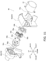
- FIG. 11 shows the panel drive unit 50 that has been disassembled.
- the panel drive unit 50 includes a motor 51, the gear 52, and a gear box 53.
- the gear shown in FIG. 11 configures a planetary gear mechanism.
- the planetary gear mechanism shown in FIG. 11 is a planetary type.
- the gear box 53 includes a motor support 53a and a gear support 53b.
- the motor 51 and the gear 52 are fixed to the casing 10 by the gear box 53.
- FIG. 12 shows the panel drive unit 50 that has been assembled.
- the motor 51 is fixed to the motor support 53a of the gear box 53 by screws (not shown) or the like.
- a sun gear 52a is fixed to a shaft 51a of the motor 51.
- Three planetary gears 52b are disposed around the sun gear 52a, and all the three planetary gears 52b are meshed with the sun gear 52a.
- FIG. 13 shows the motor 51, the motor support 53a, the sun gear 52a, and the three planetary gears 52b being assembled.
- the three planetary gears 52b are meshed with an internal gear 52c formed inside the gear support 53b.
- the internal gear 52c is fixed, and the three planetary gears 52b revolve around the sun gear 52a in accordance with a rotation of the sun gear 52a.
- Carriers 54a and 54b are attached to the three planetary gears 52b.
- the carriers 54a and 54b rotate in accordance with the revolution of the three planetary gears 52b.
- a gear 52d is fixed to the carrier 54a.
- the gear 52d rotates in accordance with the revolution of the three planetary gears 52b.
- a center axis of the gear 52d coincides with a center axis of the internal gear 52c, a center axis of the sun gear 52a, and the shaft 51a of the motor 51.
- the moving gear 52 can be concentrated near an extension line of the shaft 51a that generates the driving force by the motor 51. Therefore, the gear 52 can be disposed in a narrow space in front of the refrigerant pipes 26 of the compact indoor unit 1.
- the gear 52d is meshed with the teeth 31f disposed on the outer periphery of the joint portion 31a of the first upper crank 31.
- the gear box 53 is disposed in front of the refrigerant pipes 26 extending from the heat exchanger 20. That is, the refrigerant pipes 26 and the gear box 53 overlap each other as viewed from the front.
- the gear box 53 is disposed in front of the refrigerant pipes 26, and all the plurality of gears 52 is disposed in front of the refrigerant pipes 26.
- the two-dot chain lines indicated by reference signs CL1, CL2, and CL3 in FIG. 8 represent a center of the longitudinal direction of the heat exchanger 20, a center of the longitudinal direction of the electric component box 70, and a center of the longitudinal direction of the plurality of gears 52, respectively. As can be seen from FIG.
- the center CL3 of the longitudinal direction of the gears 52 is disposed between the center CL1 of the longitudinal direction of the heat exchanger 20 and the center CL2 of the longitudinal direction of the electric component box 70. Further, as shown in FIG. 2 , all the gears 52 are disposed at positions where the gears 52 do not overlap the heat exchanger 20 as viewed from the side.
- the gears 52 are disposed in front of the refrigerant pipes 26, and the space in front of the refrigerant pipes 26 is effectively utilized by the gears 52.
- the space that is in front of the refrigerant pipes 26 and does not overlap the heat exchanger 20 as viewed from the side is a triangular prism-shaped space at an upper front corner of the casing 10.
- all the gears 52 are disposed at the positions where the gears 52 do not overlap the heat exchanger 20 as viewed from the side.
- the coupling member 40 is disposed so as to overlap the U-shaped pipe 25 as viewed from the front.
- the space in front of the U-shaped pipe 25 is effectively utilized for the arrangement of the coupling member 40.
- the space in front of the U-shaped pipe 25 that hardly contributes to heat exchange performance is effectively utilized by the coupling member 40.
- the flow of the indoor air sucked into the heat exchanger 20 from the front suction port 4B is suppressed from being blocked by the coupling member 40. As a result, a reduction of the heat exchange performance of the indoor unit 1 can be suppressed.
- the coupling member 40 disposed so as to at least partially overlap the U-shaped pipe 25 as viewed from the front includes the first upper crank 31, the first lower crank 32, the first link 33 as the first coupling member 41, and the second upper crank 34, the second lower crank 35, and the second link 36 as the second coupling member 42.
- At least a part of the first coupling member 41 is disposed in front of the first U-shaped pipe 25a so as to overlap the first U-shaped pipe 25a as viewed from the front.
- at least a part of the second coupling member 42 is disposed in front of the second U-shaped pipe 25b so as to overlap the second U-shaped pipe 25b as viewed from the front.
- the two spaces in front of the first U-shaped pipe 25a and the second U-shaped pipe 25b are effectively utilized on both sides of the heat exchanger 20. This can enhance the effect of suppressing the reduction of the heat exchange performance of the indoor unit 1.
- the space in front of the refrigerant pipes 26 is effectively utilized by all the gears 52 disposed in front of the refrigerant pipes 26 extending from the heat exchanger 20.
- the compactness of the indoor unit 1 can be achieved.
- all the gears 52 are disposed in front of the refrigerant pipes 26.
- the compactness of the indoor unit 1 can be achieved although the degree of the effect is varied.
- all the gears 52 are disposed at positions where the gears 52 do not overlap the heat exchanger 20 as viewed from the side.
- the refrigerant pipes 26 need not to be arranged to avoid the gears 52. This makes it easy to design the arrangement of the panel drive unit 50 and the refrigerant pipes 26 in the compact indoor unit 1.
- all the gears 52 are disposed at the positions where the gears 52 do not overlap the heat exchanger 20 as viewed from the side.
- the gears 52 of the above embodiment configure the planetary gear mechanism, and thus the gears 52 as a moving part are concentrated near the extension line of the shaft 51a of the motor 51 to achieve the compactness of the indoor unit 1.
- the center CL3 of the longitudinal direction of the gears 52 disposed in front of the refrigerant pipes 26 is disposed between the heat transfer fins 23 of the heat exchanger 20 and the center CL2 of the longitudinal direction of the electric component box 70. Therefore, the effect of the compactness is enhanced.
- the center CL3 of the longitudinal direction of the gears 52 is disposed between the center CL1 of the longitudinal direction of the heat exchanger 20 and the center CL2 of the longitudinal direction of the electric component box 70.
- the indoor unit 1 can be made more compact in the longitudinal direction of the indoor unit 1 than a configuration in which the center of the gears 52 is disposed on the opposite side of the heat exchanger 20 with the electric component box 70 interposed therebetween.
- the coupling member 40 is a component member of a parallel crank mechanism that converts the rotational movement of the panel drive unit 50 into a reciprocating movement of the front panel that reciprocates between the upper front position and the rear lower position.
- a small actuator that rotates such as the motor 51 can be used for the panel drive unit 50. Therefore, the compactness can be achieved at a low cost.
- the planetary gear mechanism configured by the gears 52 of the panel drive unit 50 is the planetary type.
- the planetary gear mechanism is not limited to the planetary type, but may be, for example, a solar type or a star type. Further, the mechanism configured by the gears 52 of the panel drive unit 50 is not limited to the planetary gear mechanism.
- the coupling member 40 is a component member of the parallel crank mechanism that converts the rotational movement of the panel drive unit 50 into the reciprocating movement of the front panel 11 that reciprocates between the upper front position and the rear lower position.
- the coupling member 40 may be a component member of another crank mechanism, and is not limited to the parallel crank mechanism.
- Patent Literature 1 JP 2000-234760 A
Landscapes
- Engineering & Computer Science (AREA)
- Chemical & Material Sciences (AREA)
- Combustion & Propulsion (AREA)
- Mechanical Engineering (AREA)
- General Engineering & Computer Science (AREA)
- Physics & Mathematics (AREA)
- Thermal Sciences (AREA)
- Air Filters, Heat-Exchange Apparatuses, And Housings Of Air-Conditioning Units (AREA)
- Air-Flow Control Members (AREA)
Abstract
Description
- An indoor unit of an air conditioner with a moving front panel.
- Examples of a conventional indoor unit of an air conditioner include, as described in Patent Literature 1 (
JP 2000-234760 A - In the indoor unit disclosed in
Patent Literature 1, when a coupling member that transmits a driving force of the panel drive unit is disposed at a position where the coupling member interferes with air flowing into a heat exchanger in the compact indoor unit, heat exchange performance is reduced. - In this way, in an indoor unit of an air conditioner that moves a front panel, there is a need to address a problem how to prevent a reduction of heat exchange performance of the indoor unit caused by a coupling member.
- An indoor unit of an air conditioner according to a first aspect includes a casing that has a front panel at a front of the casing and a back surface on a rear of the casing, the back surface being fixed to a wall, a heat exchanger that is housed in the casing and has a U-shaped pipe that returns refrigerant flowing in a longitudinal direction, a panel drive unit that is housed in the casing and generates a driving force that moves the front panel by a movement of the panel drive unit itself, and a coupling member that is disposed behind the front panel, couples the front panel and the panel drive unit, and transmits the driving force from the panel drive unit to the front panel, in which the coupling member is disposed in front of the U-shaped pipe so as to at least partially overlap the U-shaped pipe as viewed from a front.
- In the indoor unit of the air conditioner, at least a part of the coupling member is disposed so as to overlap the U-shaped pipe as viewed from the front, and a space in front of the U-shaped pipe that hardly contributes to heat exchange performance is effectively utilized. As a result, a reduction of the heat exchange performance of the indoor unit can be suppressed.
- An indoor unit of an air conditioner according to a second aspect is the indoor unit according to the first aspect, in which the U-shaped pipe includes a first U-shaped pipe disposed at a first end in the longitudinal direction, and a second U-shaped pipe disposed at a second end in the longitudinal direction, and the coupling member includes a first coupling member disposed in front of the first U-shaped pipe so as to at least partially overlap the first U-shaped pipe as viewed from the front, and a second coupling member disposed in front of the second U-shaped pipe so as to at least partially overlap the second U-shaped pipe as viewed from the front. In such a configuration, two spaces in front of the first U-shaped pipe and the second U-shaped pipe are effectively utilized. This can enhance the effect of suppressing the reduction of the heat exchange performance of the indoor unit.
- An indoor unit of an air conditioner according to a third aspect is the indoor unit of the first or second aspect, in which the panel drive unit includes at least one gear disposed in front of a refrigerant pipe extending from the heat exchanger, and the coupling member rotates in accordance with a movement of the gear. This configuration allows a space in front of the refrigerant pipe to be effectively utilized. The compactness of the
indoor unit 1 can be achieved. - An indoor unit of an air conditioner according to a fourth aspect is the indoor unit according to the third aspect, in which the gear is disposed at a position where at least a part of the gear does not overlap the heat exchanger as viewed from a side. This configuration makes it easy to design an arrangement of the panel drive unit and the refrigerant pipe.
- An indoor unit of an air conditioner according to a fifth aspect is the indoor unit according to the third or fourth aspect, in which the gear configures a planetary gear mechanism. With this configuration, when a driving force is generated by a motor, for example, a moving part is easily concentrated near an extension line of a shaft to achieve the compactness of the indoor unit easily.
- An indoor unit of an air conditioner according to a sixth aspect is the indoor unit according to any one of the third to fifth aspects, further including an electric component box that is housed in the casing and electrically connected to the panel drive unit, in which the gear has a center of the longitudinal direction of the gear, the center being disposed between a center of the longitudinal direction of the heat exchanger and a center of the longitudinal direction of the electric component box. This configuration can make the indoor unit more compact in the longitudinal direction than a configuration in which the center of the gear is disposed on the opposite side of the heat exchanger with the electric component box interposed therebetween.
- An indoor unit of an air conditioner of a seventh aspect is the indoor unit of any one of the first to sixth aspects, in which the coupling member is a component member of a crank mechanism that converts a rotational movement of the panel drive unit into a reciprocating movement of the front panel that reciprocates between an upper front position and a rear lower position. This configuration allows a use of a small actuator that rotates, such as a motor, for the panel drive unit. Therefore, the compactness can be achieved at a low cost.
-
-
FIG. 1 is a cross-sectional view of an indoor unit that is stopped. -
FIG. 2 is a cross-sectional view of the indoor unit that is stopped. -
FIG. 3 is a cross-sectional view of the indoor unit in preparation for operation. -
FIG. 4 is a cross-sectional view of the indoor unit in operation. -
FIG. 5 is a perspective view of the indoor unit that is stopped. -
FIG. 6 is a perspective view of the indoor unit in operation. -
FIG. 7 is a partially enlarged perspective view showing a structure around a coupling member for driving a front panel. -
FIG. 8 is a front view showing a heat exchanger and a panel drive unit that are attached to a bottom frame. -
FIG. 9 is a front view showing the heat exchanger, the panel drive unit, and the coupling member that are attached to the bottom frame. -
FIG. 10 is a partially enlarged cross-sectional view showing the structure around the coupling member for driving the front panel. -
FIG. 11 is an exploded perspective view of the panel drive unit. -
FIG. 12 is a perspective view of the panel drive unit. -
FIG. 13 is a perspective view showing a sun gear and a planetary gear of the panel drive unit. - As shown in
FIGS. 1 to 4 , anindoor unit 1 of an air conditioner includes acasing 10, aheat exchanger 20, acoupling member 40, and apanel drive unit 50. Theheat exchanger 20 and thepanel drive unit 50 are housed in thecasing 10. Theindoor unit 1 is wall-mounted, and aback surface 10b on a rear of theindoor unit 1 is fixed to a wall. -
FIGS. 1 and2 show theindoor unit 1 that is stopped.FIG. 3 shows theindoor unit 1 preparing for operation.FIG. 4 shows theindoor unit 1 in operation.FIGS. 1 and2 are cross-sectional views of theindoor unit 1 cut at different positions along a plane extending in a front-and-rear direction and in an upper-and-lower direction. - The
casing 10 has amovable front panel 11 and a fixedupper panel 12 at a front of the casing.FIGS. 5 and6 respectively show an appearance of theindoor unit 1 that is stopped and an appearance of theindoor unit 1 in operation. As can be seen fromFIGS. 1 to 6 , when theindoor unit 1 is stopped, thefront panel 11 is closed, or in other words, thefront panel 11 is in a rear lower position. On the other hand, when theindoor unit 1 is preparing or operating, thefront panel 11 is opened, or in other words, thefront panel 11 is in an upper front position.FIG. 7 shows a configuration around thecoupling member 40 with thefront panel 11 removed from theindoor unit 1. Thecoupling member 40 is disposed behind thefront panel 11. -
FIG. 8 shows theheat exchanger 20 and thepanel drive unit 50 that are attached to abottom frame 16. Theheat exchanger 20 has aU-shaped pipe 25 that returns refrigerant flowing in a longitudinal direction (left and right direction) of theindoor unit 1 at both left and right ends of theheat exchanger 20.FIG. 9 shows thecoupling member 40 in addition to the configuration shown inFIG. 8 . As can be seen by comparingFIGS. 8 and9 , thecoupling member 40 is disposed in front of the U-shapedpipe 25 so as to at least partially overlap theU-shaped pipe 25 as viewed from the front. - The
panel drive unit 50 includes amotor 51 and a gear 52 (seeFIG. 11 ). Themotor 51 generates a driving force that moves thefront panel 11 by a rotational movement of the motor itself. The rotational movement of themotor 51 is transmitted to thecoupling member 40 through thegear 52 as the driving force for movement. - As shown in
FIG. 1 , when theindoor unit 1 is stopped, thefront panel 11 is disposed on substantially the same plane as theupper panel 12. Thefront panel 11 that is in the rear lower position when theindoor unit 1 is stopped moves to the upper front position shown inFIG. 3 when theindoor unit 1 is in preparation for operation, whereby theupper panel 12 and thefront panel 11 overlap each other as viewed from the front. After thefront panel 11 moves to the upper front position, a firsthorizontal flap 13 that configures abottom surface 10d of thecasing 10 when theindoor unit 1 is stopped rotates and moves to an upper front position as shown inFIG. 4 . - As can be seen from
FIG. 5 , thecasing 10 has a rectangular parallelepiped shape that is longer in the left and right direction. In theindoor unit 1 shown inFIG. 5 , thefront panel 11 is closed, or in other words, thefront panel 11 is in the rear lower position. On the other hand, in theindoor unit 1 shown inFIG. 6 , thefront panel 11 is opened, or in other words, thefront panel 11 is in the upper front position. Asuction port 4 includes not only anupper suction port 4A (seeFIG. 7 ) formed on a top surface 10c of thecasing 10, but also afront suction port 4B (seeFIG. 3 ) that is opened by the movement of thefront panel 11 to the upper front position when theindoor unit 1 is in operation. - The casing 10 houses a
filter 15 disposed between theheat exchanger 20 and thesuction port 4. Dust is removed, by thefilter 15, from indoor air that enters thesuction port 4 and passes through thefilter 15. The indoor air that has passed through thefilter 15 flows into theheat exchanger 20. The casing 10 houses afan 90 on a downstream side of theheat exchanger 20. Thefan 90 is, for example, a cross-flow fan that extends to left and right along the longitudinal direction of theheat exchanger 20. A blow-out passage 17 is formed on the downstream side of thefan 90. InFIG. 1 and other drawings, a plurality of blades disposed on a circumference of a partition plate is not shown because the cross-flow fan is cut at the partition plate of the cross-flow fan. - A plurality of
vertical flaps 19 arranged in the longitudinal direction (left and right direction) is attached to the blow-out passage 17. The firsthorizontal flap 13 and a secondhorizontal flap 14 are attached downstream of thevertical flap 19. An outlet of the blow-out passage 17 is a blow-outport 5. The blow-out passage 17 and thebottom surface 10d of thecasing 10 are configured by thebottom frame 16 made of resin. -
FIG. 8 shows theheat exchanger 20 and theelectric component box 70 that are disposed in thecasing 10. Theelectric component box 70 is disposed on the right of theheat exchanger 20, or in other words, closer to the right in thecasing 10. Theelectric component box 70 incorporates a control unit (not shown) that controls themotor 51, thefan 90, and the like. - As shown in
FIG. 1 , theheat exchanger 20 can be divided into a frontheat exchange section 21 and a rearheat exchange section 22. An upper part of the frontheat exchange section 21 and an upper part of the rearheat exchange section 22 are connected to each other. Due to such a structure of theheat exchanger 20, theheat exchanger 20 has a Λ shape as viewed from a side. - The
heat exchanger 20 includes a plurality of metalheat transfer fins 23 disposed side by side in the longitudinal direction, a plurality of metalheat transfer tubes 24 that extends in the longitudinal direction through the plurality ofheat transfer fins 23, the metalU-shaped pipe 25 that connects two of the heat transfer tubes in order to return and flow the refrigerant at an end of theheat exchanger 20. TheU-shaped pipe 25 includes a firstU-shaped pipe 25a disposed on the right as viewed from the front and a secondU-shaped pipe 25b disposed on the left as viewed from the front. Further, a plurality ofrefrigerant pipes 26 is connected to theheat exchanger 20. The refrigerant flows into theheat exchanger 20 from the outside through therefrigerant pipes 26, and the refrigerant flows from theheat exchanger 20 to the outside through therefrigerant pipes 26. - As shown in
FIG. 7 , thecoupling member 40 includes a first upper crank 31, a first lower crank 32, afirst link 33, a second upper crank 34, a second lower crank 35, and asecond link 36. The first upper crank 31, the first lower crank 32, and thefirst link 33 are afirst coupling member 41, and configure a first parallel crank mechanism. The second upper crank 34, the second lower crank 35, and thesecond link 36 are asecond coupling member 42 and configure a second parallel crank mechanism. - As shown in
FIGS. 8 and9 , the first upper crank 31, the first lower crank 32, and thefirst link 33 that configure the first parallel crank mechanism of thecoupling member 40 do not overlap theheat transfer fins 23 of theheat exchanger 20 at all as viewed from the front. The first upper crank 31, the first lower crank 32, and thefirst link 33 are in a range in which the firstU-shaped pipe 25a is disposed, in the longitudinal direction as viewed from the front. The second upper crank 34, the second lower crank 35, and thesecond link 36 that configure the second parallel crank mechanism partially overlap theheat transfer fins 23 of theheat exchanger 20 as viewed from the front. The second upper crank 34, the second lower crank 35, and thesecond link 36 also partially overlap the secondU-shaped pipe 25b as viewed from the front. - Therefore, the first upper crank 31, the first lower crank 32, and the
first link 33 that configure thefirst coupling member 41 of thecoupling member 40 do not disturb a flow of the indoor air flowing to theheat transfer fins 23 of theheat exchanger 20. Further, the second upper crank 34, the second lower crank 35 and thesecond link 36 that configure thesecond coupling member 42 partially overlap theheat transfer fins 23 but protrude toward the secondU-shaped pipe 25b as viewed from the front. This suppresses disturbing the flow of the indoor air flowing to theheat transfer fins 23 at a left end of theheat exchanger 20. In particular, when thefront panel 11 is opened, most of the second upper crank 34 and the second lower crank 35 are away from theheat transfer fins 23. Sufficient indoor air flows to theheat transfer fins 23 on the left end of theheat exchanger 20 similarly to the other parts. -
FIG. 10 mainly shows the second parallel crank mechanism. The second upper crank 34 of the second parallel crank mechanism is bent in an L shape as viewed from the side. Ajoint portion 34a is formed with asquare coupling hole 34b into which a metal shaft 100 (seeFIG. 8 ) having a square cross section is fitted. When themotor 51 rotates, the rotational movement of themotor 51 is transmitted to themetal shaft 100 via thegear 52. Further, the rotational movement of themetal shaft 100 is transmitted to thejoint portion 34a. Aninner arm 34c extends from thejoint portion 34a. Theinner arm 34c has a relatively short arm length so as not to collide with theupper panel 12 of thecasing 10, theheat exchanger 20, and the like in a rotation range of theinner arm 34c. A direction in which apanel side arm 34d extends outward from theinner arm 34c is bent upward by about 90 degrees with respect to a direction in which theinner arm 34c extends as viewed from the side. Thepanel side arm 34d has an arm length longer than the arm length of theinner arm 34c in order to increase a moving distance of thefront panel 11. Ashaft 34e is provided at a panel side tip of thepanel side arm 34d. - The
shaft 34e of the second upper crank 34 is fitted into abearing 36a provided at an upper end of thesecond link 36. Theshaft 34e can rotate in thebearing 36a. Amain portion 36b of thesecond link 36 extending downward from thebearing 36a also serves as an attachment plate to which thefront panel 11 is attached. Thefront panel 11 is fixed to themain portion 36b with a pressure sensitive adhesive and/or an adhesive. Abearing 36c is provided at a lower end of thesecond link 36. - A
shaft 35a of the second lower crank 35 is fitted into the bearing 36c of thesecond link 36. Theshaft 35a can rotate in thebearing 36c. Anarm 35b extends from theshaft 35a of the second lower crank 35 toward acasing body 10g in the back. Thecasing body 10g is a part of thecasing 10 excluding thefront panel 11. Ashaft 35c is provided at the other end of thearm 35b. Theshaft 35c of the second lower crank 35 is fitted into abearing 10j of thecasing body 10g. Theshaft 35c of the second lower crank 35 can rotate in thebearing 10j. That is, thecasing body 10g serves as a fixed link of the second parallel crank mechanism. -
FIG. 2 mainly shows the first parallel crank mechanism. The first upper crank 31 of the first parallel crank mechanism is bent in an L shape as viewed from the side. Ajoint portion 31a is formed with asquare coupling hole 31b into which the metal shaft 100 (seeFIG. 8 ) having a square cross section is fitted. A plurality ofteeth 31f meshed with thegear 52 is formed on an outer periphery of thejoint portion 31a. When themotor 51 rotates, the rotational movement of themotor 51 is transmitted to the plurality ofteeth 31f via thegear 52, and then the first upper crank 31 rotates. At this time, the rotational movement of the first upper crank 31 is transmitted to themetal shaft 100, and the rotational movement of themetal shaft 100 is transmitted to thejoint portion 34a. Aninner arm 31c extends from thejoint portion 31a. Theinner arm 31c has a relatively short arm length so as not to collide with theupper panel 12 of thecasing 10, theheat exchanger 20, and the like in a rotation range of theinner arm 31c. A direction in which apanel side arm 31d extends outward from theinner arm 31c is bent upward by about 90 degrees with respect to a direction in which theinner arm 31c extends as viewed from the side. Thepanel side arm 31d has an arm length longer than the arm length of theinner arm 31c in order to increase a moving distance of thefront panel 11. In this way, the first upper crank 31 has theinner arm 31c and thepanel side arm 31d having substantially the same shapes as the shapes of theinner arm 34c and thepanel side arm 34d of the second upper crank 34 described above. Ashaft 31e is provided at a panel side tip of thepanel side arm 31d. - The
shaft 31e of the first upper crank 31 is fitted into abearing 33a provided at an upper end of thefirst link 33. Theshaft 31e can rotate in thebearing 33a. Amain portion 33b of thefirst link 33 extending downward from thebearing 33a also serves as an attachment plate to which thefront panel 11 is attached. Thefront panel 11 is fixed to themain portion 33b with a pressure sensitive adhesive and/or an adhesive. Abearing 33c is provided at a lower end of thefirst link 33. - A
shaft 32a of the first lower crank 32 is fitted into the bearing 33c of thefirst link 33. Theshaft 32a can rotate in thebearing 33c. Anarm 32b extends from theshaft 32a of the first lower crank 32 toward thecasing body 10g in the back. A shaft (not shown) is provided at the other end of thearm 32b. The shaft of the first lower crank 32 is fitted into a bearing (not shown) of thecasing body 10g. The shaft of the first lower crank 32 can rotate in the bearing of thecasing body 10g. That is, thecasing body 10g also serves as a fixed link of the first parallel crank mechanism. -
FIG. 11 shows thepanel drive unit 50 that has been disassembled. Thepanel drive unit 50 includes amotor 51, thegear 52, and agear box 53. The gear shown inFIG. 11 configures a planetary gear mechanism. The planetary gear mechanism shown inFIG. 11 is a planetary type. Thegear box 53 includes amotor support 53a and agear support 53b. Themotor 51 and thegear 52 are fixed to thecasing 10 by thegear box 53.FIG. 12 shows thepanel drive unit 50 that has been assembled. - The
motor 51 is fixed to themotor support 53a of thegear box 53 by screws (not shown) or the like. Asun gear 52a is fixed to ashaft 51a of themotor 51. Threeplanetary gears 52b are disposed around thesun gear 52a, and all the threeplanetary gears 52b are meshed with thesun gear 52a.FIG. 13 shows themotor 51, themotor support 53a, thesun gear 52a, and the threeplanetary gears 52b being assembled. - The three
planetary gears 52b are meshed with aninternal gear 52c formed inside thegear support 53b. Theinternal gear 52c is fixed, and the threeplanetary gears 52b revolve around thesun gear 52a in accordance with a rotation of thesun gear 52a.Carriers planetary gears 52b. Thecarriers planetary gears 52b. Agear 52d is fixed to thecarrier 54a. Thus, thegear 52d rotates in accordance with the revolution of the threeplanetary gears 52b. A center axis of thegear 52d coincides with a center axis of theinternal gear 52c, a center axis of thesun gear 52a, and theshaft 51a of themotor 51. Due to such a structure, the movinggear 52 can be concentrated near an extension line of theshaft 51a that generates the driving force by themotor 51. Therefore, thegear 52 can be disposed in a narrow space in front of therefrigerant pipes 26 of the compactindoor unit 1. Thegear 52d is meshed with theteeth 31f disposed on the outer periphery of thejoint portion 31a of the first upper crank 31. - As shown in
FIG. 8 , thegear box 53 is disposed in front of therefrigerant pipes 26 extending from theheat exchanger 20. That is, therefrigerant pipes 26 and thegear box 53 overlap each other as viewed from the front. In this embodiment, thegear box 53 is disposed in front of therefrigerant pipes 26, and all the plurality ofgears 52 is disposed in front of therefrigerant pipes 26. Further, the two-dot chain lines indicated by reference signs CL1, CL2, and CL3 inFIG. 8 represent a center of the longitudinal direction of theheat exchanger 20, a center of the longitudinal direction of theelectric component box 70, and a center of the longitudinal direction of the plurality ofgears 52, respectively. As can be seen fromFIG. 8 , the center CL3 of the longitudinal direction of thegears 52 is disposed between the center CL1 of the longitudinal direction of theheat exchanger 20 and the center CL2 of the longitudinal direction of theelectric component box 70. Further, as shown inFIG. 2 , all thegears 52 are disposed at positions where thegears 52 do not overlap theheat exchanger 20 as viewed from the side. - In this way, the
gears 52 are disposed in front of therefrigerant pipes 26, and the space in front of therefrigerant pipes 26 is effectively utilized by thegears 52. As a result, the compactness of theindoor unit 1 can be achieved. The space that is in front of therefrigerant pipes 26 and does not overlap theheat exchanger 20 as viewed from the side is a triangular prism-shaped space at an upper front corner of thecasing 10. In this embodiment, all thegears 52 are disposed at the positions where thegears 52 do not overlap theheat exchanger 20 as viewed from the side. However, when at least a part of thegears 52 is disposed at a position where the part of thegears 52 does not overlap theheat exchanger 20 as viewed from the side, there is an effect of the easy designing although the degree of the effect is varied. When thegears 52 partially overlap theheat exchanger 20 as viewed from the side, it is easy to make theindoor unit 1 compact. - For example, as described with reference to
FIGS. 8 and9 , in theindoor unit 1 described above, at least a part of thecoupling member 40 is disposed so as to overlap theU-shaped pipe 25 as viewed from the front. In this way, the space in front of theU-shaped pipe 25 is effectively utilized for the arrangement of thecoupling member 40. The space in front of theU-shaped pipe 25 that hardly contributes to heat exchange performance is effectively utilized by thecoupling member 40. The flow of the indoor air sucked into theheat exchanger 20 from thefront suction port 4B is suppressed from being blocked by thecoupling member 40. As a result, a reduction of the heat exchange performance of theindoor unit 1 can be suppressed. - The
coupling member 40 disposed so as to at least partially overlap theU-shaped pipe 25 as viewed from the front includes the first upper crank 31, the first lower crank 32, thefirst link 33 as thefirst coupling member 41, and the second upper crank 34, the second lower crank 35, and thesecond link 36 as thesecond coupling member 42. At least a part of thefirst coupling member 41 is disposed in front of the firstU-shaped pipe 25a so as to overlap the firstU-shaped pipe 25a as viewed from the front. Further, at least a part of thesecond coupling member 42 is disposed in front of the secondU-shaped pipe 25b so as to overlap the secondU-shaped pipe 25b as viewed from the front. The two spaces in front of the firstU-shaped pipe 25a and the secondU-shaped pipe 25b are effectively utilized on both sides of theheat exchanger 20. This can enhance the effect of suppressing the reduction of the heat exchange performance of theindoor unit 1. - In the
panel drive unit 50 of the above embodiment, the space in front of therefrigerant pipes 26 is effectively utilized by all thegears 52 disposed in front of therefrigerant pipes 26 extending from theheat exchanger 20. The compactness of theindoor unit 1 can be achieved. In this embodiment, all thegears 52 are disposed in front of therefrigerant pipes 26. However, when a part of thegear 52 is disposed in front of therefrigerant pipes 26, the compactness of theindoor unit 1 can be achieved although the degree of the effect is varied. - In the above embodiment, all the
gears 52 are disposed at positions where thegears 52 do not overlap theheat exchanger 20 as viewed from the side. Thus, therefrigerant pipes 26 need not to be arranged to avoid thegears 52. This makes it easy to design the arrangement of thepanel drive unit 50 and therefrigerant pipes 26 in the compactindoor unit 1. In this embodiment, all thegears 52 are disposed at the positions where thegears 52 do not overlap theheat exchanger 20 as viewed from the side. However, when a part of thegears 52 is disposed at a position where the part of thegears 52 does not overlap theheat exchanger 20 as viewed from the side, the easy designing of the arrangement of thepanel drive unit 50 and therefrigerant pipes 26 can be achieved although the degree of the effect is varied. - The
gears 52 of the above embodiment configure the planetary gear mechanism, and thus thegears 52 as a moving part are concentrated near the extension line of theshaft 51a of themotor 51 to achieve the compactness of theindoor unit 1. In particular, the center CL3 of the longitudinal direction of thegears 52 disposed in front of therefrigerant pipes 26 is disposed between theheat transfer fins 23 of theheat exchanger 20 and the center CL2 of the longitudinal direction of theelectric component box 70. Therefore, the effect of the compactness is enhanced. - As described with reference to
FIG. 8 , the center CL3 of the longitudinal direction of thegears 52 is disposed between the center CL1 of the longitudinal direction of theheat exchanger 20 and the center CL2 of the longitudinal direction of theelectric component box 70. Thus, theindoor unit 1 can be made more compact in the longitudinal direction of theindoor unit 1 than a configuration in which the center of thegears 52 is disposed on the opposite side of theheat exchanger 20 with theelectric component box 70 interposed therebetween. - The
coupling member 40 is a component member of a parallel crank mechanism that converts the rotational movement of thepanel drive unit 50 into a reciprocating movement of the front panel that reciprocates between the upper front position and the rear lower position. With thecoupling member 40 configured as above, a small actuator that rotates such as themotor 51 can be used for thepanel drive unit 50. Therefore, the compactness can be achieved at a low cost. - In the description of the above embodiment, the planetary gear mechanism configured by the
gears 52 of thepanel drive unit 50 is the planetary type. The planetary gear mechanism, however, is not limited to the planetary type, but may be, for example, a solar type or a star type. Further, the mechanism configured by thegears 52 of thepanel drive unit 50 is not limited to the planetary gear mechanism. - In the description of the above embodiment, the
coupling member 40 is a component member of the parallel crank mechanism that converts the rotational movement of thepanel drive unit 50 into the reciprocating movement of thefront panel 11 that reciprocates between the upper front position and the rear lower position. Thecoupling member 40, however, may be a component member of another crank mechanism, and is not limited to the parallel crank mechanism. - Although the embodiment of the present invention has been described above, it will be understood that various changes in forms and details can be made without departing from the gist and scope of the present invention as set forth in the claims.
-
- 1
- Indoor unit
- 10
- Casing
- 11
- Front panel
- 20
- Heat exchanger
- 25
- U-shaped pipe
- 25a
- First U-shaped pipe
- 25b
- Second U-shaped pipe
- 40
- Coupling member
- 41
- First coupling member
- 42
- Second coupling member
- 50
- Panel drive unit
- 51
- Motor
- 52
- Gear
- 70
- Electric component box
- Patent Literature 1:
JP 2000-234760 A
Claims (7)
- An indoor unit (1) of an air conditioner, comprising:a casing (10) that has a front panel (11) at a front of the casing and a back surface on a rear of the casing, the back surface being fixed to a wall;a heat exchanger (20) that is housed in the casing and has a U-shaped pipe (25, 25a, 25b) that returns refrigerant flowing in a longitudinal direction;a panel drive unit (50) that is housed in the casing and generates a driving force that moves the front panel by a movement of the panel drive unit itself; anda coupling member (40) that is disposed behind the front panel, couples the front panel and the panel drive unit, and transmits the driving force from the panel drive unit to the front panel,wherein the coupling member is disposed in front of the U-shaped pipe so as to at least partially overlap the U-shaped pipe as viewed from a front.
- The indoor unit (1) of an air conditioner according to claim 1,wherein the U-shaped pipe includes a first U-shaped pipe (25a) disposed at a first end in the longitudinal direction, and a second U-shaped pipe (25b) disposed at a second end in the longitudinal direction, andthe coupling member includes a first coupling member (41) disposed in front of the first U-shaped pipe so as to at least partially overlap the first U-shaped pipe as viewed from the front, and a second coupling member (42) disposed in front of the second U-shaped pipe so as to at least partially overlap the second U-shaped pipe as viewed from the front.
- The indoor unit (1) of an air conditioner according to claim 1 or 2,wherein the panel drive unit includes at least one gear (52) disposed in front of a refrigerant pipe extending from the heat exchanger, andthe coupling member rotates in accordance with a movement of the gear.
- The indoor unit (1) of an air conditioner according to claim 3, wherein the gear is disposed at a position where at least a part of the gear does not overlap the heat exchanger as viewed from a side.
- The indoor unit (1) of an air conditioner according to claim 3 or 4, wherein the gear configures a planetary gear mechanism.
- The indoor unit (1) of an air conditioner according to any one of claims 3 to 5, further comprising an electric component box (70) that is housed in the casing and electrically connected to the panel drive unit,
wherein the gear has a center of the longitudinal direction of the gear, the center being disposed between a center of the longitudinal direction of the heat exchanger and a center of the longitudinal direction of the electric component box. - The indoor unit (1) of an air conditioner according to any one of claims 1 to 6, wherein the coupling member is a component member of a crank mechanism that converts a rotational movement of the panel drive unit into a reciprocating movement of the front panel that reciprocates between an upper front position and a rear lower position.
Applications Claiming Priority (2)
| Application Number | Priority Date | Filing Date | Title |
|---|---|---|---|
| JP2017222704A JP6610644B2 (en) | 2017-11-20 | 2017-11-20 | Air conditioner indoor unit |
| PCT/JP2018/042297 WO2019098276A1 (en) | 2017-11-20 | 2018-11-15 | Indoor unit for air conditioner |
Publications (2)
| Publication Number | Publication Date |
|---|---|
| EP3715741A1 true EP3715741A1 (en) | 2020-09-30 |
| EP3715741A4 EP3715741A4 (en) | 2021-01-13 |
Family
ID=66537835
Family Applications (1)
| Application Number | Title | Priority Date | Filing Date |
|---|---|---|---|
| EP18877770.0A Withdrawn EP3715741A4 (en) | 2017-11-20 | 2018-11-15 | INDOOR UNIT FOR AIR CONDITIONING |
Country Status (6)
| Country | Link |
|---|---|
| US (1) | US11041642B2 (en) |
| EP (1) | EP3715741A4 (en) |
| JP (1) | JP6610644B2 (en) |
| CN (1) | CN111356884B (en) |
| AU (1) | AU2018367564B2 (en) |
| WO (1) | WO2019098276A1 (en) |
Families Citing this family (4)
| Publication number | Priority date | Publication date | Assignee | Title |
|---|---|---|---|---|
| CN212511740U (en) * | 2020-04-30 | 2021-02-09 | 广东美的制冷设备有限公司 | Air conditioner shell subassembly and air conditioner |
| KR20230025388A (en) * | 2020-05-19 | 2023-02-21 | 퍼스펙티브 로보틱스 아게 | Air vehicle storage case with platform |
| CN116465023B (en) * | 2022-01-12 | 2025-12-19 | 青岛海尔空调器有限总公司 | Indoor unit of vertical air conditioner |
| CN115523536B (en) * | 2022-08-29 | 2024-06-07 | 珠海格力电器股份有限公司 | Indoor unit, air conditioner and control method of indoor unit |
Family Cites Families (27)
| Publication number | Priority date | Publication date | Assignee | Title |
|---|---|---|---|---|
| JPH0658179B2 (en) * | 1989-12-20 | 1994-08-03 | ダイキン工業株式会社 | Air conditioner indoor unit |
| JPH07133941A (en) * | 1993-11-10 | 1995-05-23 | Noritz Corp | Structure of electric accessory case |
| JP3507268B2 (en) * | 1997-02-19 | 2004-03-15 | 東芝キヤリア株式会社 | Indoor unit of air conditioner |
| TW384374B (en) | 1996-10-03 | 2000-03-11 | Toshiba Corp | Indoor unit of air-conditioner |
| JP3234553B2 (en) * | 1997-09-30 | 2001-12-04 | 三洋電機株式会社 | Electrical box and air conditioner using the electrical box |
| JP3967029B2 (en) | 1999-02-15 | 2007-08-29 | 株式会社富士通ゼネラル | Air conditioner |
| JP4437029B2 (en) * | 2003-11-19 | 2010-03-24 | パナソニック株式会社 | Air conditioner |
| JP3864951B2 (en) * | 2003-11-19 | 2007-01-10 | 松下電器産業株式会社 | Air conditioner |
| JP4262579B2 (en) | 2003-11-19 | 2009-05-13 | パナソニック株式会社 | Air conditioner |
| JP4313184B2 (en) | 2003-12-25 | 2009-08-12 | 東芝キヤリア株式会社 | Air conditioner indoor unit |
| KR20060010085A (en) * | 2004-07-27 | 2006-02-02 | 엘지전자 주식회사 | Front panel opening and closing structure of indoor unit |
| KR101123316B1 (en) * | 2004-08-16 | 2012-03-20 | 엘지전자 주식회사 | Air conditioner |
| JP4624174B2 (en) * | 2004-08-27 | 2011-02-02 | 三洋電機株式会社 | Air conditioner |
| CN2800137Y (en) * | 2005-06-14 | 2006-07-26 | 广东美的电器股份有限公司 | Indoor unit of split type air conditioner |
| KR20090000950U (en) * | 2007-07-26 | 2009-02-02 | 삼성전자주식회사 | Air conditioner |
| KR101404694B1 (en) | 2007-10-24 | 2014-06-09 | 엘지전자 주식회사 | Indoor unit of an air conditioner |
| KR101606006B1 (en) | 2009-01-20 | 2016-03-24 | 삼성전자 주식회사 | Air conditioner |
| US10060645B2 (en) * | 2014-06-19 | 2018-08-28 | Mitsubishi Electric Corporation | Indoor unit of air-conditioning apparatus and air-conditioning apparatus including the indoor unit |
| KR20160080314A (en) | 2014-12-26 | 2016-07-08 | 주식회사 포스코 | Ferritic stainless steel and method for manufacturing the same |
| JP6538374B2 (en) | 2015-03-02 | 2019-07-03 | シャープ株式会社 | Air conditioner |
| US9970671B2 (en) * | 2015-05-27 | 2018-05-15 | Haier Us Appliance Solutions, Inc. | Bulkhead assemblies and methods for air conditioner units |
| EP3333496A4 (en) * | 2015-08-06 | 2019-04-17 | Mitsubishi Electric Corporation | AIR CONDITIONER |
| US9927044B2 (en) * | 2015-12-21 | 2018-03-27 | Kmc Controls, Inc. | Dual shaft alternating drive actuator |
| KR102414268B1 (en) * | 2016-07-22 | 2022-06-29 | 엘지전자 주식회사 | Air conditioner |
| KR102645875B1 (en) * | 2016-10-21 | 2024-03-11 | 삼성전자주식회사 | Air conditioner |
| US10488071B2 (en) * | 2017-02-15 | 2019-11-26 | Haier Us Appliance Solutions, Inc. | Packaged terminal air conditioner unit with vent door position detection |
| CN107166520B (en) | 2017-05-27 | 2019-12-06 | 青岛海尔空调器有限总公司 | Wall-mounted air conditioner indoor unit |
-
2017
- 2017-11-20 JP JP2017222704A patent/JP6610644B2/en active Active
-
2018
- 2018-11-15 EP EP18877770.0A patent/EP3715741A4/en not_active Withdrawn
- 2018-11-15 AU AU2018367564A patent/AU2018367564B2/en not_active Ceased
- 2018-11-15 WO PCT/JP2018/042297 patent/WO2019098276A1/en not_active Ceased
- 2018-11-15 CN CN201880074499.7A patent/CN111356884B/en active Active
- 2018-11-15 US US16/765,409 patent/US11041642B2/en not_active Expired - Fee Related
Also Published As
| Publication number | Publication date |
|---|---|
| WO2019098276A1 (en) | 2019-05-23 |
| CN111356884B (en) | 2021-03-26 |
| JP6610644B2 (en) | 2019-11-27 |
| AU2018367564B2 (en) | 2021-04-29 |
| EP3715741A4 (en) | 2021-01-13 |
| CN111356884A (en) | 2020-06-30 |
| US20200326078A1 (en) | 2020-10-15 |
| US11041642B2 (en) | 2021-06-22 |
| JP2019095093A (en) | 2019-06-20 |
| AU2018367564A1 (en) | 2020-07-09 |
Similar Documents
| Publication | Publication Date | Title |
|---|---|---|
| US11041642B2 (en) | Indoor unit of air conditioner | |
| CN112413728B (en) | Air conditioner | |
| CN102317635B (en) | Air Conditioned Outdoor Unit | |
| KR20140050735A (en) | Indoor unit of air conditioner | |
| CN106796038B (en) | Outdoor unit of air conditioner | |
| CN208418969U (en) | Swing blade assembly and air conditioner for wall-mounted air conditioner indoor unit | |
| CN215982930U (en) | Air conditioner outdoor unit and air conditioner | |
| CN104197419A (en) | Cabinet type air conditioner indoor unit | |
| CN204678510U (en) | Window-mounted air conditioner | |
| EP3382290A1 (en) | Air conditioner | |
| CN100412457C (en) | Air conditioner | |
| CN208059131U (en) | Package AC plant | |
| US20120175089A1 (en) | Outdoor unit for air conditioner | |
| CN211476089U (en) | Air conditioner indoor unit and air conditioner | |
| WO2020157824A1 (en) | Outdoor unit for air conditioner | |
| CN105674529A (en) | Driving device and cabinet air conditioner | |
| CN204901969U (en) | Cabinet air conditioner guider and through -flow cabinet air conditioner | |
| CN211261053U (en) | Window type air conditioner | |
| CN207763064U (en) | Air-conditioning equipment | |
| CN212618807U (en) | Volute front partition plate and window type air conditioner | |
| CN104019534A (en) | Blade driving method, blade driving device and air conditioner indoor unit | |
| US9689577B2 (en) | Outdoor unit for air-conditioning apparatus | |
| CN204901967U (en) | Cabinet air conditioner drive gear and through -flow cabinet air conditioner | |
| CN204901974U (en) | Through -flow cabinet air conditioner | |
| CN207922506U (en) | Drive component and air-conditioning equipment |
Legal Events
| Date | Code | Title | Description |
|---|---|---|---|
| STAA | Information on the status of an ep patent application or granted ep patent |
Free format text: STATUS: THE INTERNATIONAL PUBLICATION HAS BEEN MADE |
|
| PUAI | Public reference made under article 153(3) epc to a published international application that has entered the european phase |
Free format text: ORIGINAL CODE: 0009012 |
|
| STAA | Information on the status of an ep patent application or granted ep patent |
Free format text: STATUS: REQUEST FOR EXAMINATION WAS MADE |
|
| 17P | Request for examination filed |
Effective date: 20200602 |
|
| AK | Designated contracting states |
Kind code of ref document: A1 Designated state(s): AL AT BE BG CH CY CZ DE DK EE ES FI FR GB GR HR HU IE IS IT LI LT LU LV MC MK MT NL NO PL PT RO RS SE SI SK SM TR |
|
| AX | Request for extension of the european patent |
Extension state: BA ME |
|
| A4 | Supplementary search report drawn up and despatched |
Effective date: 20201211 |
|
| RIC1 | Information provided on ipc code assigned before grant |
Ipc: F24F 13/20 20060101AFI20201207BHEP Ipc: F24F 13/10 20060101ALI20201207BHEP Ipc: F24F 1/0068 20190101ALI20201207BHEP Ipc: F24F 1/0057 20190101ALI20201207BHEP |
|
| DAV | Request for validation of the european patent (deleted) | ||
| DAX | Request for extension of the european patent (deleted) | ||
| STAA | Information on the status of an ep patent application or granted ep patent |
Free format text: STATUS: EXAMINATION IS IN PROGRESS |
|
| 17Q | First examination report despatched |
Effective date: 20211027 |
|
| GRAP | Despatch of communication of intention to grant a patent |
Free format text: ORIGINAL CODE: EPIDOSNIGR1 |
|
| STAA | Information on the status of an ep patent application or granted ep patent |
Free format text: STATUS: GRANT OF PATENT IS INTENDED |
|
| INTG | Intention to grant announced |
Effective date: 20221006 |
|
| RAP3 | Party data changed (applicant data changed or rights of an application transferred) |
Owner name: DAIKIN INDUSTRIES, LTD. |
|
| GRAJ | Information related to disapproval of communication of intention to grant by the applicant or resumption of examination proceedings by the epo deleted |
Free format text: ORIGINAL CODE: EPIDOSDIGR1 |
|
| STAA | Information on the status of an ep patent application or granted ep patent |
Free format text: STATUS: EXAMINATION IS IN PROGRESS |
|
| INTC | Intention to grant announced (deleted) | ||
| P01 | Opt-out of the competence of the unified patent court (upc) registered |
Effective date: 20230525 |
|
| STAA | Information on the status of an ep patent application or granted ep patent |
Free format text: STATUS: THE APPLICATION IS DEEMED TO BE WITHDRAWN |
|
| 18D | Application deemed to be withdrawn |
Effective date: 20230624 |