EP3715706A1 - Automobilbeleuchtungsvorrichtung und verfahren zur herstellung einer automobilbeleuchtungsvorrichtung - Google Patents
Automobilbeleuchtungsvorrichtung und verfahren zur herstellung einer automobilbeleuchtungsvorrichtung Download PDFInfo
- Publication number
- EP3715706A1 EP3715706A1 EP19166387.1A EP19166387A EP3715706A1 EP 3715706 A1 EP3715706 A1 EP 3715706A1 EP 19166387 A EP19166387 A EP 19166387A EP 3715706 A1 EP3715706 A1 EP 3715706A1
- Authority
- EP
- European Patent Office
- Prior art keywords
- lighting device
- automotive lighting
- foldable
- slim
- fitting element
- Prior art date
- Legal status (The legal status is an assumption and is not a legal conclusion. Google has not performed a legal analysis and makes no representation as to the accuracy of the status listed.)
- Withdrawn
Links
Images

Classifications
-
- F—MECHANICAL ENGINEERING; LIGHTING; HEATING; WEAPONS; BLASTING
- F21—LIGHTING
- F21S—NON-PORTABLE LIGHTING DEVICES; SYSTEMS THEREOF; VEHICLE LIGHTING DEVICES SPECIALLY ADAPTED FOR VEHICLE EXTERIORS
- F21S41/00—Illuminating devices specially adapted for vehicle exteriors, e.g. headlamps
- F21S41/30—Illuminating devices specially adapted for vehicle exteriors, e.g. headlamps characterised by reflectors
- F21S41/37—Illuminating devices specially adapted for vehicle exteriors, e.g. headlamps characterised by reflectors characterised by their material, surface treatment or coatings
Definitions
- the present invention belongs to the field of lamps for automotive vehicles, and more specifically, to the design and manufacturing of optic reflectors.
- Current headlamps comprise metallized reflectors, which are in charge of projecting the light emitted by the light sources.
- these parts are usually manufactured in plastic, and then covered by metal particles, in a metallization process.
- metal particles in a metallization process.
- the metallization particles do not reach the whole reflector surface, since there are zones which are not easily accessible under vacuum conditions.
- Another solution would be to introduce holes on the reflector sides to allow accessibility of metallization vapours to the reflective walls. However, these holes would worsen the luminous behaviour of the lighting reflector.
- the invention provides a solution for improving the manufacturing of a reflector by the provision of an automotive lighting device according to claim 1 and a method for manufacturing an automotive lighting device according to claim 11.
- Preferred embodiments of the invention are defined in dependent claims.
- the invention provides an automotive lighting device comprising an optic reflector which comprises a first portion and a second portion, wherein
- This solution avoid any photometry problems caused by holes in the reflector or by the joint line generated when demoulding a reflector with tight demoulding angles, and it further solves the metallization problems, since the shadow generated by the second portion is eliminated: the reflector may be metallized with the second portion being open and then the second portion may be closed to form the final reflector.
- This optic reflector may be manufactured in a single piece, avoiding problems associated to using several moulds.
- the automotive lighting device comprises more than one foldable slim zones, and further comprises a reinforce element between the slim zones.
- plastic material flowability does not allow a very slim foldable zone, so a single slim zone may not be enough for a 180o folding operation. In these cases, more than one slim zones may be provided, to perform a sequential folding and get the second portion be closed over the first portion.
- the optic reflector is made of plastic.
- Plastic is the common material for performing these elements, being a cheap one and accepting a further metallization process.
- the first portion comprises a first fitting element and the second portion comprises a second fitting element, and the first fitting element and the second fitting element are intended to be coupled.
- first fitting element and the second fitting element form a clipping joint. In other embodiments, the first fitting element and the second fitting element form a snap fit joint. In different embodiments, the first fitting element and the second fitting element form a pressure joint.
- the automotive lighting device further comprises solid-state light sources.
- solid state refers to light emitted by solid-state electroluminescence, which uses semiconductors to convert electricity into light. Compared to incandescent lighting, solid state lighting creates visible light with reduced heat generation and less energy dissipation.
- the typically small mass of a solid-state electronic lighting device provides for greater resistance to shock and vibration compared to brittle glass tubes/bulbs and long, thin filament wires. They also eliminate filament evaporation, potentially increasing the life span of the illumination device.
- Some examples of these types of lighting comprise semiconductor light-emitting diodes (LEDs), organic light-emitting diodes (OLED), or polymer light-emitting diodes (PLED) as sources of illumination rather than electrical filaments, plasma or gas.
- the light sources are mounted in a printed circuit board.
- the automotive lighting device may be specially designed for LEDs, wherein these LEDs may be mounted in a printed circuit board and emit light towards the reflector.
- the optic reflector comprises more than one reflective cavities.
- LEDs arrangements involve the use of different cavities in the reflector, so that each cavity reflects the light emitted by one of the LEDs.
- the invention provides a method for manufacturing an automotive lighting device according to the first inventive aspect, the method comprising the steps of
- This method is advantageous since it provides an easy and reliable way of obtaining a lighting device with a convenient metallization without substantially altering the final shape of the optic reflector.
- the method further comprises the step of calculating the number of foldable slim zones depending on the flowability of the plastic material.
- Figure 1 shows a particular embodiment of an optic reflector 2 used in an automotive lighting device according to the invention, before being finished.
- This optic reflector 2 comprises a first portion 3 and a second portion 4 joined by a foldable slim zone 5.
- This foldable slim zone 5 is configured to be bended to allow the second portion 4 be coupled to the first portion 3.
- the first portion 3 comprises a first fitting element 7 and the second portion 4 comprises a second fitting element 8. This bending is not shown in this figure yet.
- the optic reflector 2 is manufactured by mould injection of a plastic material.
- the mould follows the shape shown in figure 1 .
- the size of the foldable slim zone is carefully calculated by mould flow simulations, so that this part of the mould is thick enough for a plastic material to flow through.
- Figure 2 shows a detail of this bending portion.
- the calculations mentioned before provide the number of foldable slim zones which are necessary to guarantee a feasible manufacturing process and a feasible bending of the second portion over the first portion.
- this figure 2 shows two foldable slim zones 5, 5' between first and second portions 3, 4, with a reinforce element 6 between the slim zones 5, 5'. This reinforce element 6 divides the slim zone for a better behaviour of the plastic material in the manufacturing process.
- the plastic material is injected in the mould to form the optic reflector.
- the optic reflector is unmoulded, thus obtaining an element as the one of figure 1 .
- the optic reflector is metallized, taking advantage of the absence of shadows provided by the open second portion 4. As a consequence, the metallization particles may reach the whole inner surface of the reflector 2 and then achieve a successful metallization process.
- the second portion 4 is bended over the first portion 3 and adjusted by some fitting elements.
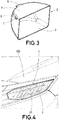
- Figure 3 shows a finished optic reflector 2 according to the invention, once the second portion 4 has been bended over the first portion 3 by means of folding over the foldable slim portion 5.
- the first portion 3 comprises a first fitting element 7 and the second portion 4 comprises a second fitting element 8.
- Both first and second fitting elements 7, 8 provide a clipping joint which adjusts the second portion 4 to form the final structure of the optical reflector 2.
- FIG. 4 shows a lighting device 1 according to the invention installed in an automotive vehicle 100.
- This automotive lighting device 1 comprises a plurality of LEDs 20 and a housing which encloses an optical reflector 2 specially adapted for LEDs, with a printed circuit board to receive the LEDs and a plurality of cavities to project the light emitted by each one of them.
Priority Applications (1)
| Application Number | Priority Date | Filing Date | Title |
|---|---|---|---|
| EP19166387.1A EP3715706A1 (de) | 2019-03-29 | 2019-03-29 | Automobilbeleuchtungsvorrichtung und verfahren zur herstellung einer automobilbeleuchtungsvorrichtung |
Applications Claiming Priority (1)
| Application Number | Priority Date | Filing Date | Title |
|---|---|---|---|
| EP19166387.1A EP3715706A1 (de) | 2019-03-29 | 2019-03-29 | Automobilbeleuchtungsvorrichtung und verfahren zur herstellung einer automobilbeleuchtungsvorrichtung |
Publications (1)
| Publication Number | Publication Date |
|---|---|
| EP3715706A1 true EP3715706A1 (de) | 2020-09-30 |
Family
ID=66041340
Family Applications (1)
| Application Number | Title | Priority Date | Filing Date |
|---|---|---|---|
| EP19166387.1A Withdrawn EP3715706A1 (de) | 2019-03-29 | 2019-03-29 | Automobilbeleuchtungsvorrichtung und verfahren zur herstellung einer automobilbeleuchtungsvorrichtung |
Country Status (1)
| Country | Link |
|---|---|
| EP (1) | EP3715706A1 (de) |
Citations (6)
| Publication number | Priority date | Publication date | Assignee | Title |
|---|---|---|---|---|
| EP0253243A1 (de) * | 1986-07-16 | 1988-01-20 | Valeo Vision | Reflektor für Kraftfahrzeugscheinwerfer mit verbessertem Fernlicht |
| EP0895021A2 (de) * | 1997-07-02 | 1999-02-03 | Osram Sylvania Inc. | Röhrenförmige Lampe und Reflektor-Einheit |
| FR2953277A1 (fr) * | 2009-11-27 | 2011-06-03 | Peugeot Citroen Automobiles Sa | Masque de bloc optique de vehicule, a paroi partiellement deplacable |
| WO2011107908A1 (en) * | 2010-03-03 | 2011-09-09 | Koninklijke Philips Electronics N.V. | Collimator |
| WO2014056012A1 (de) * | 2012-10-09 | 2014-04-17 | Zizala Lichtsysteme Gmbh | Lichtmodul mit zwei oder mehr reflektoren für ein kraftfahrzeug |
| DE102015225664A1 (de) * | 2015-12-17 | 2017-06-22 | Automotive Lighting Reutlingen Gmbh | Reflektoranordnung für ein Lichtmodul einer Kraftfahrzeugbeleuchtungseinrichtung |
-
2019
- 2019-03-29 EP EP19166387.1A patent/EP3715706A1/de not_active Withdrawn
Patent Citations (6)
| Publication number | Priority date | Publication date | Assignee | Title |
|---|---|---|---|---|
| EP0253243A1 (de) * | 1986-07-16 | 1988-01-20 | Valeo Vision | Reflektor für Kraftfahrzeugscheinwerfer mit verbessertem Fernlicht |
| EP0895021A2 (de) * | 1997-07-02 | 1999-02-03 | Osram Sylvania Inc. | Röhrenförmige Lampe und Reflektor-Einheit |
| FR2953277A1 (fr) * | 2009-11-27 | 2011-06-03 | Peugeot Citroen Automobiles Sa | Masque de bloc optique de vehicule, a paroi partiellement deplacable |
| WO2011107908A1 (en) * | 2010-03-03 | 2011-09-09 | Koninklijke Philips Electronics N.V. | Collimator |
| WO2014056012A1 (de) * | 2012-10-09 | 2014-04-17 | Zizala Lichtsysteme Gmbh | Lichtmodul mit zwei oder mehr reflektoren für ein kraftfahrzeug |
| DE102015225664A1 (de) * | 2015-12-17 | 2017-06-22 | Automotive Lighting Reutlingen Gmbh | Reflektoranordnung für ein Lichtmodul einer Kraftfahrzeugbeleuchtungseinrichtung |
Similar Documents
| Publication | Publication Date | Title |
|---|---|---|
| US9453619B2 (en) | Retrofit-style lamp and fixture, each including a one-dimensional linear batwing lens | |
| US10054278B2 (en) | Vehicle headlamp | |
| US10161614B2 (en) | Retrofit lamp for automotive headlights | |
| US9116280B2 (en) | Holding frame for an optical element | |
| US20170030557A1 (en) | Optical structure | |
| CN101387378A (zh) | 汽车专用led照明模块 | |
| US20110260638A1 (en) | Reflector-type lamp with integrated heat distribution and emi shielding | |
| EP3715706A1 (de) | Automobilbeleuchtungsvorrichtung und verfahren zur herstellung einer automobilbeleuchtungsvorrichtung | |
| US20150233532A1 (en) | Light source device | |
| CN204786014U (zh) | 散热良好的led前照灯光源组件 | |
| WO2021115775A1 (en) | Vehicle lighting device | |
| EP3715707A1 (de) | Automobilbeleuchtungsvorrichtung und verfahren zur herstellung einer automobilbeleuchtungsvorrichtung | |
| WO2022129392A1 (en) | Automotive luminous module and method for manufacturing an automotive luminous module | |
| US10690308B2 (en) | Automotive lighting device | |
| EP3562273A1 (de) | Elektronische anordnung und beleuchtungsvorrichtung | |
| US10584846B2 (en) | Lighting device with lens and method for production thereof | |
| EP3716733A1 (de) | Elektronische baugruppe und kraftfahrzeugbeleuchtungsvorrichtung | |
| KR20100069471A (ko) | 차량용 헤드램프 | |
| EP4203198A1 (de) | Kraftfahrzeugleuchtvorrichtung | |
| EP3916295A1 (de) | Automobilbeleuchtungsvorrichtung | |
| EP3290782A1 (de) | Beleuchtungsvorrichtung für ein kraftfahrzeug und herstellungsverfahren dafür | |
| EP3657067B1 (de) | Automobilbeleuchtungsvorrichtung und verfahren zur herstellung einer automobilbeleuchtungsvorrichtung | |
| WO2023083903A1 (en) | Automotive lighting device | |
| EP3660393B1 (de) | Autobeleuchtungsvorrichtung | |
| US10330287B2 (en) | Light for room and building illumination |
Legal Events
| Date | Code | Title | Description |
|---|---|---|---|
| PUAI | Public reference made under article 153(3) epc to a published international application that has entered the european phase |
Free format text: ORIGINAL CODE: 0009012 |
|
| STAA | Information on the status of an ep patent application or granted ep patent |
Free format text: STATUS: THE APPLICATION HAS BEEN PUBLISHED |
|
| AK | Designated contracting states |
Kind code of ref document: A1 Designated state(s): AL AT BE BG CH CY CZ DE DK EE ES FI FR GB GR HR HU IE IS IT LI LT LU LV MC MK MT NL NO PL PT RO RS SE SI SK SM TR |
|
| AX | Request for extension of the european patent |
Extension state: BA ME |
|
| STAA | Information on the status of an ep patent application or granted ep patent |
Free format text: STATUS: REQUEST FOR EXAMINATION WAS MADE |
|
| 17P | Request for examination filed |
Effective date: 20210309 |
|
| RBV | Designated contracting states (corrected) |
Designated state(s): AL AT BE BG CH CY CZ DE DK EE ES FI FR GB GR HR HU IE IS IT LI LT LU LV MC MK MT NL NO PL PT RO RS SE SI SK SM TR |
|
| STAA | Information on the status of an ep patent application or granted ep patent |
Free format text: STATUS: EXAMINATION IS IN PROGRESS |
|
| 17Q | First examination report despatched |
Effective date: 20220818 |
|
| STAA | Information on the status of an ep patent application or granted ep patent |
Free format text: STATUS: THE APPLICATION HAS BEEN WITHDRAWN |
|
| 18W | Application withdrawn |
Effective date: 20230220 |
|
| P01 | Opt-out of the competence of the unified patent court (upc) registered |
Effective date: 20230629 |