EP3715668B1 - Gas turbine engine comprising a shiftable transmission - Google Patents
Gas turbine engine comprising a shiftable transmission Download PDFInfo
- Publication number
- EP3715668B1 EP3715668B1 EP19215833.5A EP19215833A EP3715668B1 EP 3715668 B1 EP3715668 B1 EP 3715668B1 EP 19215833 A EP19215833 A EP 19215833A EP 3715668 B1 EP3715668 B1 EP 3715668B1
- Authority
- EP
- European Patent Office
- Prior art keywords
- shaft
- gas turbine
- turbine engine
- clutch
- gear
- Prior art date
- Legal status (The legal status is an assumption and is not a legal conclusion. Google has not performed a legal analysis and makes no representation as to the accuracy of the status listed.)
- Active
Links
Images


Classifications
-
- F—MECHANICAL ENGINEERING; LIGHTING; HEATING; WEAPONS; BLASTING
- F16—ENGINEERING ELEMENTS AND UNITS; GENERAL MEASURES FOR PRODUCING AND MAINTAINING EFFECTIVE FUNCTIONING OF MACHINES OR INSTALLATIONS; THERMAL INSULATION IN GENERAL
- F16H—GEARING
- F16H3/00—Toothed gearings for conveying rotary motion with variable gear ratio or for reversing rotary motion
- F16H3/006—Toothed gearings for conveying rotary motion with variable gear ratio or for reversing rotary motion power being selectively transmitted by parallel flow paths, e.g. dual clutch transmissions
-
- F—MECHANICAL ENGINEERING; LIGHTING; HEATING; WEAPONS; BLASTING
- F02—COMBUSTION ENGINES; HOT-GAS OR COMBUSTION-PRODUCT ENGINE PLANTS
- F02C—GAS-TURBINE PLANTS; AIR INTAKES FOR JET-PROPULSION PLANTS; CONTROLLING FUEL SUPPLY IN AIR-BREATHING JET-PROPULSION PLANTS
- F02C7/00—Features, components parts, details or accessories, not provided for in, or of interest apart form groups F02C1/00 - F02C6/00; Air intakes for jet-propulsion plants
- F02C7/36—Power transmission arrangements between the different shafts of the gas turbine plant, or between the gas-turbine plant and the power user
-
- F—MECHANICAL ENGINEERING; LIGHTING; HEATING; WEAPONS; BLASTING
- F02—COMBUSTION ENGINES; HOT-GAS OR COMBUSTION-PRODUCT ENGINE PLANTS
- F02C—GAS-TURBINE PLANTS; AIR INTAKES FOR JET-PROPULSION PLANTS; CONTROLLING FUEL SUPPLY IN AIR-BREATHING JET-PROPULSION PLANTS
- F02C3/00—Gas-turbine plants characterised by the use of combustion products as the working fluid
- F02C3/04—Gas-turbine plants characterised by the use of combustion products as the working fluid having a turbine driving a compressor
- F02C3/107—Gas-turbine plants characterised by the use of combustion products as the working fluid having a turbine driving a compressor with two or more rotors connected by power transmission
- F02C3/113—Gas-turbine plants characterised by the use of combustion products as the working fluid having a turbine driving a compressor with two or more rotors connected by power transmission with variable power transmission between rotors
-
- F—MECHANICAL ENGINEERING; LIGHTING; HEATING; WEAPONS; BLASTING
- F02—COMBUSTION ENGINES; HOT-GAS OR COMBUSTION-PRODUCT ENGINE PLANTS
- F02C—GAS-TURBINE PLANTS; AIR INTAKES FOR JET-PROPULSION PLANTS; CONTROLLING FUEL SUPPLY IN AIR-BREATHING JET-PROPULSION PLANTS
- F02C7/00—Features, components parts, details or accessories, not provided for in, or of interest apart form groups F02C1/00 - F02C6/00; Air intakes for jet-propulsion plants
- F02C7/32—Arrangement, mounting, or driving, of auxiliaries
-
- F—MECHANICAL ENGINEERING; LIGHTING; HEATING; WEAPONS; BLASTING
- F02—COMBUSTION ENGINES; HOT-GAS OR COMBUSTION-PRODUCT ENGINE PLANTS
- F02K—JET-PROPULSION PLANTS
- F02K3/00—Plants including a gas turbine driving a compressor or a ducted fan
- F02K3/02—Plants including a gas turbine driving a compressor or a ducted fan in which part of the working fluid by-passes the turbine and combustion chamber
- F02K3/04—Plants including a gas turbine driving a compressor or a ducted fan in which part of the working fluid by-passes the turbine and combustion chamber the plant including ducted fans, i.e. fans with high volume, low pressure outputs, for augmenting the jet thrust, e.g. of double-flow type
- F02K3/06—Plants including a gas turbine driving a compressor or a ducted fan in which part of the working fluid by-passes the turbine and combustion chamber the plant including ducted fans, i.e. fans with high volume, low pressure outputs, for augmenting the jet thrust, e.g. of double-flow type with front fan
-
- F—MECHANICAL ENGINEERING; LIGHTING; HEATING; WEAPONS; BLASTING
- F16—ENGINEERING ELEMENTS AND UNITS; GENERAL MEASURES FOR PRODUCING AND MAINTAINING EFFECTIVE FUNCTIONING OF MACHINES OR INSTALLATIONS; THERMAL INSULATION IN GENERAL
- F16H—GEARING
- F16H3/00—Toothed gearings for conveying rotary motion with variable gear ratio or for reversing rotary motion
- F16H3/02—Toothed gearings for conveying rotary motion with variable gear ratio or for reversing rotary motion without gears having orbital motion
- F16H3/08—Toothed gearings for conveying rotary motion with variable gear ratio or for reversing rotary motion without gears having orbital motion exclusively or essentially with continuously meshing gears, that can be disengaged from their shafts
- F16H3/087—Toothed gearings for conveying rotary motion with variable gear ratio or for reversing rotary motion without gears having orbital motion exclusively or essentially with continuously meshing gears, that can be disengaged from their shafts characterised by the disposition of the gears
- F16H3/093—Toothed gearings for conveying rotary motion with variable gear ratio or for reversing rotary motion without gears having orbital motion exclusively or essentially with continuously meshing gears, that can be disengaged from their shafts characterised by the disposition of the gears with two or more countershafts
-
- F—MECHANICAL ENGINEERING; LIGHTING; HEATING; WEAPONS; BLASTING
- F05—INDEXING SCHEMES RELATING TO ENGINES OR PUMPS IN VARIOUS SUBCLASSES OF CLASSES F01-F04
- F05D—INDEXING SCHEME FOR ASPECTS RELATING TO NON-POSITIVE-DISPLACEMENT MACHINES OR ENGINES, GAS-TURBINES OR JET-PROPULSION PLANTS
- F05D2260/00—Function
- F05D2260/40—Transmission of power
- F05D2260/403—Transmission of power through the shape of the drive components
- F05D2260/4031—Transmission of power through the shape of the drive components as in toothed gearing
-
- F—MECHANICAL ENGINEERING; LIGHTING; HEATING; WEAPONS; BLASTING
- F05—INDEXING SCHEMES RELATING TO ENGINES OR PUMPS IN VARIOUS SUBCLASSES OF CLASSES F01-F04
- F05D—INDEXING SCHEME FOR ASPECTS RELATING TO NON-POSITIVE-DISPLACEMENT MACHINES OR ENGINES, GAS-TURBINES OR JET-PROPULSION PLANTS
- F05D2260/00—Function
- F05D2260/40—Transmission of power
- F05D2260/403—Transmission of power through the shape of the drive components
- F05D2260/4031—Transmission of power through the shape of the drive components as in toothed gearing
- F05D2260/40311—Transmission of power through the shape of the drive components as in toothed gearing of the epicyclical, planetary or differential type
-
- F—MECHANICAL ENGINEERING; LIGHTING; HEATING; WEAPONS; BLASTING
- F16—ENGINEERING ELEMENTS AND UNITS; GENERAL MEASURES FOR PRODUCING AND MAINTAINING EFFECTIVE FUNCTIONING OF MACHINES OR INSTALLATIONS; THERMAL INSULATION IN GENERAL
- F16H—GEARING
- F16H3/00—Toothed gearings for conveying rotary motion with variable gear ratio or for reversing rotary motion
- F16H3/02—Toothed gearings for conveying rotary motion with variable gear ratio or for reversing rotary motion without gears having orbital motion
- F16H3/08—Toothed gearings for conveying rotary motion with variable gear ratio or for reversing rotary motion without gears having orbital motion exclusively or essentially with continuously meshing gears, that can be disengaged from their shafts
- F16H2003/0818—Toothed gearings for conveying rotary motion with variable gear ratio or for reversing rotary motion without gears having orbital motion exclusively or essentially with continuously meshing gears, that can be disengaged from their shafts comprising means for power-shifting
-
- F—MECHANICAL ENGINEERING; LIGHTING; HEATING; WEAPONS; BLASTING
- F16—ENGINEERING ELEMENTS AND UNITS; GENERAL MEASURES FOR PRODUCING AND MAINTAINING EFFECTIVE FUNCTIONING OF MACHINES OR INSTALLATIONS; THERMAL INSULATION IN GENERAL
- F16H—GEARING
- F16H3/00—Toothed gearings for conveying rotary motion with variable gear ratio or for reversing rotary motion
- F16H3/02—Toothed gearings for conveying rotary motion with variable gear ratio or for reversing rotary motion without gears having orbital motion
- F16H3/08—Toothed gearings for conveying rotary motion with variable gear ratio or for reversing rotary motion without gears having orbital motion exclusively or essentially with continuously meshing gears, that can be disengaged from their shafts
- F16H3/087—Toothed gearings for conveying rotary motion with variable gear ratio or for reversing rotary motion without gears having orbital motion exclusively or essentially with continuously meshing gears, that can be disengaged from their shafts characterised by the disposition of the gears
- F16H3/093—Toothed gearings for conveying rotary motion with variable gear ratio or for reversing rotary motion without gears having orbital motion exclusively or essentially with continuously meshing gears, that can be disengaged from their shafts characterised by the disposition of the gears with two or more countershafts
- F16H2003/0931—Toothed gearings for conveying rotary motion with variable gear ratio or for reversing rotary motion without gears having orbital motion exclusively or essentially with continuously meshing gears, that can be disengaged from their shafts characterised by the disposition of the gears with two or more countershafts each countershaft having an output gear meshing with a single common gear on the output shaft
-
- F—MECHANICAL ENGINEERING; LIGHTING; HEATING; WEAPONS; BLASTING
- F16—ENGINEERING ELEMENTS AND UNITS; GENERAL MEASURES FOR PRODUCING AND MAINTAINING EFFECTIVE FUNCTIONING OF MACHINES OR INSTALLATIONS; THERMAL INSULATION IN GENERAL
- F16H—GEARING
- F16H2200/00—Transmissions for multiple ratios
- F16H2200/003—Transmissions for multiple ratios characterised by the number of forward speeds
- F16H2200/0043—Transmissions for multiple ratios characterised by the number of forward speeds the gear ratios comprising four forward speeds
Definitions
- the present invention relates to gas turbine engines.
- Gas turbine engines are utilized to power aircraft, providing thrust to propel the aircraft. Further, mechanical energy is often extracted from the gas turbine engine to provide electrical power to various aircraft components and systems through a generator, at which rotational energy extracted from the gas turbine engine is used to generate electrical power.
- the present invention provides a gas turbine engine according to claim 1.
- the dependent claims concern particular embodiments of the invention as defined in claim
- FIG. 1 schematically illustrates a gas turbine engine 20.
- the gas turbine engine 20 is disclosed herein as a two-spool turbofan that generally incorporates a fan section 22, a compressor section 24, a combustor section 26 and a turbine section 28.
- Alternative engines might include other systems or features.
- the fan section 22 drives air along a bypass flow path B in a bypass duct, while the compressor section 24 drives air along a core flow path C for compression and communication into the combustor section 26 then expansion through the turbine section 28.
- FIG. 1 schematically illustrates a gas turbine engine 20.
- the gas turbine engine 20 is disclosed herein as a two-spool turbofan that generally incorporates a fan section 22, a compressor section 24, a combustor section 26 and a turbine section 28.
- Alternative engines might include other systems or features.
- the fan section 22 drives air along a bypass flow path B in a bypass duct
- the compressor section 24 drives air along a core flow path C for compression and communication into the combustor section 26
- the exemplary engine 20 generally includes a low speed spool 30 and a high speed spool 32 mounted for rotation about an engine central longitudinal axis A relative to an engine static structure 36 via several bearing systems 38. It should be understood that various bearing systems 38 at various locations may alternatively or additionally be provided, and the location of bearing systems 38 may be varied as appropriate to the application.
- the low speed spool 30 generally includes an inner shaft 40 that interconnects a fan 42, a low pressure compressor 44 and a low pressure turbine 46.
- the inner shaft 40 is connected to the fan 42 through a speed change mechanism, which in exemplary gas turbine engine 20 is illustrated as a geared architecture 48 to drive the fan 42 at a lower speed than the low speed spool 30.
- the high speed spool 32 includes an outer shaft 50 that interconnects a high pressure compressor 52 and high pressure turbine 54.
- a combustor 56 is arranged in exemplary gas turbine 20 between the high pressure compressor 52 and the high pressure turbine 54.
- An engine static structure 36 is arranged generally between the high pressure turbine 54 and the low pressure turbine 46.
- the engine static structure 36 further supports bearing systems 38 in the turbine section 28.
- the inner shaft 40 and the outer shaft 50 are concentric and rotate via bearing systems 38 about the engine central longitudinal axis A which is collinear with their longitudinal axes.
- each of the positions of the fan section 22, compressor section 24, combustor section 26, turbine section 28, and fan drive gear system 48 may be varied.
- gear system 48 may be located aft of combustor section 26 or even aft of turbine section 28, and fan section 22 may be positioned forward or aft of the location of gear system 48.
- a power takeoff or tower shaft 58 is operably connected to the inner shaft 40 to extract rotational energy therefrom.
- the rotational energy of the tower shaft 58 is utilized by a generator 60, which converts the rotational energy to electrical energy to power accessory components and/or aircraft systems (not shown).
- a transmission 62 is located upstream of generator 60 to provide an output rotational speed to the generator 60 within a selected speed range for use by the generator 60.
- the transmission 62 receives input rotational energy via an input shaft, for example, the tower shaft 58, and outputs rotational energy toward the generator 60 via, for example, output shaft 64.
- the transmission 62 includes a plurality of gear ratios 66, for example, four gear ratios 66. While four gear ratios 66 are illustrated and described herein, one skilled in the art will readily appreciate that other numbers of gear ratios 66, for example, three, five or six gear ratios 66 may be utilized depending on need of the particular system, to cover a required inner shaft 40 rotational speed range.
- Each gear ratio 66 is connected to a clutch lay shaft 68.
- two clutch lay shafts 68 are utilized, with two gear ratios 66 operably connected to each of the two clutch lay shafts 68.
- first gear ratio 66a and third gear ratio 66c are operably connected to a first lay shaft 68a
- second gear ratio 68b and fourth gear ratio 68d are operably connected to a second lay shaft 68b.
- Each gear ratio (66a, 66b, 66c, 66d) has a respective input gear (70a, 70b, 70c, 70d) located at and rotatable with the input shaft 58.
- the input gears (70a, 70b, 70c, 70d) are selectably engagable with a respective ratio output gear (72a, 72b, 72c, 72d) disposed at and rotatable with the associated clutch lay shaft (68a 68b).
- a first ratio output gear 72a and a third ratio output gear 72c are located at the first clutch lay shaft 68a, while a second ratio output gear 72b and a fourth ratio output gear 72d are located at the second clutch lay shaft 68b.
- the gear ratios (66a, 66b, 66c, 66d) are selectably engaged through the selective engagement and disengagement of a plurality of clutches (74a, 74b, 74c, 74d).
- Each clutch (74a, 74b, 74c, 74d) is associated with only one gear ratio, and a different one, of the plurality of gear ratios (66a, 66b, 66c, 66d).
- the clutches (74a, 74b, 74c, 74d) are located at the clutch lay shafts (68a, 68b) and are each operably connected to one of the ratio output gears (72a, 72b, 72c, 72d).
- first clutch 74a is located at the first clutch lay shaft 68a and is operably connected to the first ratio output gear 72a and rotates with the clutch lay shaft 68a. Disengagement or opening of the clutch 74a engages the first ratio output gear 72a with the first input gear 70a resulting in the rotation of the first clutch lay shaft 68a at the selected rotational speed.
- the arrangement and operation of the other clutches 74 at the outer ratio output gears 72 is similar, and for the sake of brevity will not be described in detail herein.
- the rotational speed of the first clutch lay shaft 68a and the second clutch lay shaft 68b is dependent on the selective disengagement or opening of clutches (74a, 74b, 74c, 74d) causing selective engagement of one of the ratio output gears (72a, 72b, 72c, 72d) with their respective input gear (70a, 70b, 70c, 70d).
- Each clutch lay shaft (68a, 68b) includes a lay shaft output gear (76a, 76b), which is engaged with a secondary shaft 78 through engagement with a secondary shaft input gear 80.
- the engagement drives rotation of the secondary shaft 78, which is connected to the output shaft 64 through engagement of a secondary shaft output gear 82 of the secondary shaft 78 with an output shaft gear 84 of the output shaft 64.
- FIG. 3 illustrated is a cross-sectional view of the transmission 62 at the first clutch lay shaft 68a.
- the cross-sectional view of FIG. 3 illustrates first clutch 74a and third clutch 74c disposed at the first clutch lay shaft 68a to control selective engagement of the first gear ratio 66a and the third gear ratio 66b.
- Rotational energy is transferred from the first clutch lay shaft 68a to the secondary shaft 78 via the engagement of first lay shaft output gear 76a with secondary shaft input gear 80.
- the secondary shaft 78 is coaxial with the input shaft 58.
- FIGs. 4 and 5 illustrate schematic axial cross-sectional views of the view of the transmission 62 at input gear 70 and secondary shaft input gear 80, respectively.
- each gear ratio (66a, 66b, 66c, 66d) is configured to provide an output speed in the same output speed range over a different range of input speeds.
- the transmission 62 is configured such that the output speed range of the output shaft 64 is in the range of 8000 rpm to 16000 rpm.
- Use of the multiple gear ratios 66 allows the transfer of usable rotational energy in the form of output rotational speed from the transmission 62 from the tower shaft 58 to the generator 60 over a wide range of input speeds of the tower shaft 68, corresponding to a wide range of inner shaft 40 rotational speeds. Further, this approach and configuration has the benefit of being simple in that it only uses gears and clutches 74, with one clutch 74 per gear ratio 66. There is no need to utilize additional one-way clutches or synchromesh arrangements, which are typical in such transmissions. Also, torque through the transmission 62 may be held consistent as one clutch 74 can close while the next clutch 74 opens.
Landscapes
- Engineering & Computer Science (AREA)
- General Engineering & Computer Science (AREA)
- Chemical & Material Sciences (AREA)
- Combustion & Propulsion (AREA)
- Mechanical Engineering (AREA)
- Structure Of Transmissions (AREA)
Description
- The present invention relates to gas turbine engines.
- Gas turbine engines are utilized to power aircraft, providing thrust to propel the aircraft. Further, mechanical energy is often extracted from the gas turbine engine to provide electrical power to various aircraft components and systems through a generator, at which rotational energy extracted from the gas turbine engine is used to generate electrical power.
- Most modern gas turbine engines have multiple spools, e.g. a low pressure spool and a high pressure spool. Traditionally, the high pressure spool is used to drive the various aircraft components and systems via the generator. Efficiency concerns led to a desire to move power extraction from the high pressure spool to the low pressure spool. The low pressure spool, however, is typically not used for power extraction due to the larger range of operating speeds of the lower pressure spool, compared to a the range of operating speeds of the high pressure spool.
EP 3438431 A1 discloses a gas turbine engine according to the preamble of claim 1.JP H02 11951 - The present invention provides a gas turbine engine according to claim 1. The dependent claims concern particular embodiments of the invention as defined in claim
- With reference to the accompanying drawings, like elements are numbered alike:
-
FIG. 1 is a schematic illustration of an exemplary gas turbine engine; -
FIG. 2 is a schematic illustration of a power transmission for a gas turbine engine; -
FIG. 3 is a cross-sectional view of an embodiment of a power transmission of a gas turbine engine; -
FIG. 4 is another cross-sectional view of an embodiment of a power transmission of a gas turbine engine; -
FIG. 5 is another cross-sectional view of an embodiment of a power transmission of a gas turbine engine; and -
FIG. 6 is a graph illustrating input speed to output speed of a power transmission. - A detailed description of one or more embodiments of the claimed invention are presented herein by way of exemplification and not limitation with reference to the Figures.
-
FIG. 1 schematically illustrates agas turbine engine 20. Thegas turbine engine 20 is disclosed herein as a two-spool turbofan that generally incorporates afan section 22, acompressor section 24, acombustor section 26 and aturbine section 28. Alternative engines might include other systems or features. Thefan section 22 drives air along a bypass flow path B in a bypass duct, while thecompressor section 24 drives air along a core flow path C for compression and communication into thecombustor section 26 then expansion through theturbine section 28. Although depicted as a two-spool turbofan gas turbine engine in the disclosed non-limiting embodiment, it should be understood that the concepts described herein are not limited to use with two-spool turbofans as the teachings may be applied to other types of turbine engines including three-spool architectures. - The
exemplary engine 20 generally includes alow speed spool 30 and ahigh speed spool 32 mounted for rotation about an engine central longitudinal axis A relative to an enginestatic structure 36 viaseveral bearing systems 38. It should be understood thatvarious bearing systems 38 at various locations may alternatively or additionally be provided, and the location ofbearing systems 38 may be varied as appropriate to the application. - The
low speed spool 30 generally includes aninner shaft 40 that interconnects afan 42, alow pressure compressor 44 and alow pressure turbine 46. Theinner shaft 40 is connected to thefan 42 through a speed change mechanism, which in exemplarygas turbine engine 20 is illustrated as a gearedarchitecture 48 to drive thefan 42 at a lower speed than thelow speed spool 30. Thehigh speed spool 32 includes anouter shaft 50 that interconnects ahigh pressure compressor 52 andhigh pressure turbine 54. Acombustor 56 is arranged inexemplary gas turbine 20 between thehigh pressure compressor 52 and thehigh pressure turbine 54. An enginestatic structure 36 is arranged generally between thehigh pressure turbine 54 and thelow pressure turbine 46. The enginestatic structure 36 further supports bearingsystems 38 in theturbine section 28. Theinner shaft 40 and theouter shaft 50 are concentric and rotate viabearing systems 38 about the engine central longitudinal axis A which is collinear with their longitudinal axes. - The core airflow is compressed by the
low pressure compressor 44 then thehigh pressure compressor 52, mixed and burned with fuel in thecombustor 56, then expanded over thehigh pressure turbine 54 andlow pressure turbine 46. Theturbines low speed spool 30 andhigh speed spool 32 in response to the expansion. It will be appreciated that each of the positions of thefan section 22,compressor section 24,combustor section 26,turbine section 28, and fandrive gear system 48 may be varied. For example,gear system 48 may be located aft ofcombustor section 26 or even aft ofturbine section 28, andfan section 22 may be positioned forward or aft of the location ofgear system 48. - A power takeoff or
tower shaft 58 is operably connected to theinner shaft 40 to extract rotational energy therefrom. The rotational energy of thetower shaft 58 is utilized by agenerator 60, which converts the rotational energy to electrical energy to power accessory components and/or aircraft systems (not shown). Because theinner shaft 40 has a large operating speed range, larger than is useful or compatible with thegenerator 60, atransmission 62 is located upstream ofgenerator 60 to provide an output rotational speed to thegenerator 60 within a selected speed range for use by thegenerator 60. - Referring now to
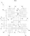
FIG. 2 , a schematic illustration of an embodiment of thetransmission 62 is illustrated. Thetransmission 62 receives input rotational energy via an input shaft, for example, thetower shaft 58, and outputs rotational energy toward thegenerator 60 via, for example,output shaft 64. Thetransmission 62 includes a plurality of gear ratios 66, for example, four gear ratios 66. While four gear ratios 66 are illustrated and described herein, one skilled in the art will readily appreciate that other numbers of gear ratios 66, for example, three, five or six gear ratios 66 may be utilized depending on need of the particular system, to cover a requiredinner shaft 40 rotational speed range. - Each gear ratio 66 is connected to a clutch lay shaft 68. In the embodiment of
FIG. 2 , two clutch lay shafts 68 are utilized, with two gear ratios 66 operably connected to each of the two clutch lay shafts 68. For example,first gear ratio 66a andthird gear ratio 66c are operably connected to afirst lay shaft 68a, whilesecond gear ratio 68b and fourth gear ratio 68d are operably connected to asecond lay shaft 68b. Each gear ratio (66a, 66b, 66c, 66d) has a respective input gear (70a, 70b, 70c, 70d) located at and rotatable with theinput shaft 58. The input gears (70a, 70b, 70c, 70d) are selectably engagable with a respective ratio output gear (72a, 72b, 72c, 72d) disposed at and rotatable with the associated clutch lay shaft (68a 68b). In the embodiment ofFIG. 2 , a firstratio output gear 72a and a thirdratio output gear 72c are located at the firstclutch lay shaft 68a, while a secondratio output gear 72b and a fourthratio output gear 72d are located at the secondclutch lay shaft 68b. - The gear ratios (66a, 66b, 66c, 66d) are selectably engaged through the selective engagement and disengagement of a plurality of clutches (74a, 74b, 74c, 74d). Each clutch (74a, 74b, 74c, 74d) is associated with only one gear ratio, and a different one, of the plurality of gear ratios (66a, 66b, 66c, 66d). The clutches (74a, 74b, 74c, 74d) are located at the clutch lay shafts (68a, 68b) and are each operably connected to one of the ratio output gears (72a, 72b, 72c, 72d). In this embodiment,
first clutch 74a is located at the firstclutch lay shaft 68a and is operably connected to the firstratio output gear 72a and rotates with theclutch lay shaft 68a. Disengagement or opening of theclutch 74a engages the firstratio output gear 72a with thefirst input gear 70a resulting in the rotation of the firstclutch lay shaft 68a at the selected rotational speed. - The arrangement and operation of the other clutches 74 at the outer ratio output gears 72 is similar, and for the sake of brevity will not be described in detail herein. The rotational speed of the first
clutch lay shaft 68a and the secondclutch lay shaft 68b is dependent on the selective disengagement or opening of clutches (74a, 74b, 74c, 74d) causing selective engagement of one of the ratio output gears (72a, 72b, 72c, 72d) with their respective input gear (70a, 70b, 70c, 70d). - Each clutch lay shaft (68a, 68b) includes a lay shaft output gear (76a, 76b), which is engaged with a
secondary shaft 78 through engagement with a secondaryshaft input gear 80. The engagement drives rotation of thesecondary shaft 78, which is connected to theoutput shaft 64 through engagement of a secondaryshaft output gear 82 of thesecondary shaft 78 with anoutput shaft gear 84 of theoutput shaft 64. - Referring now to
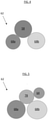
FIG. 3 , illustrated is a cross-sectional view of thetransmission 62 at the firstclutch lay shaft 68a. The cross-sectional view ofFIG. 3 illustratesfirst clutch 74a andthird clutch 74c disposed at the firstclutch lay shaft 68a to control selective engagement of thefirst gear ratio 66a and thethird gear ratio 66b. Rotational energy is transferred from the firstclutch lay shaft 68a to thesecondary shaft 78 via the engagement of first layshaft output gear 76a with secondaryshaft input gear 80. In some embodiments, as shown, thesecondary shaft 78 is coaxial with theinput shaft 58.FIGs. 4 and 5 illustrate schematic axial cross-sectional views of the view of thetransmission 62 at input gear 70 and secondaryshaft input gear 80, respectively. - Referring now to
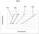
FIG. 6 , illustrated is a graph of input speed to output speed ranges of each of the gear ratios (66a, 66b, 66c, 66d). Each gear ratio (66a, 66b, 66c, 66d) is configured to provide an output speed in the same output speed range over a different range of input speeds. In some embodiments, thetransmission 62 is configured such that the output speed range of theoutput shaft 64 is in the range of 8000 rpm to 16000 rpm. - Use of the multiple gear ratios 66 allows the transfer of usable rotational energy in the form of output rotational speed from the
transmission 62 from thetower shaft 58 to thegenerator 60 over a wide range of input speeds of the tower shaft 68, corresponding to a wide range ofinner shaft 40 rotational speeds. Further, this approach and configuration has the benefit of being simple in that it only uses gears and clutches 74, with one clutch 74 per gear ratio 66. There is no need to utilize additional one-way clutches or synchromesh arrangements, which are typical in such transmissions. Also, torque through thetransmission 62 may be held consistent as one clutch 74 can close while the next clutch 74 opens. - The term "about" is intended to include the degree of error associated with measurement of the particular quantity based upon the equipment available at the time of filing the application. For example, "about" can include a range of ± 8% or 5%, or 2% of a given value.
Claims (10)
- A gas turbine engine (20), comprising:a turbine rotating via a gas turbine engine shaft (40);a tower shaft (58) operably connected to the gas turbine engine shaft (40) configured as a power takeoff of rotational energy from the gas turbine engine shaft (40); anda power transmission (62); the gas turbine engine characterized in that the power transmission comprises:an input shaft;an output shaft (64);a plurality of gear ratios (66a-d) to transfer rotational energy from the input shaft to the output shaft (64) to drive the output shaft (64) at a selected output shaft speed; anda plurality of clutches (74a-d), each clutch disposed at a clutch lay shaft (68a,b) of a plurality of clutch lay shafts and configured to control selective engagement of only one gear ratio of the plurality of gear ratios, wherein each gear ratio (66a-d) comprises:an input gear (70a-d) disposed at and rotatable with the input shaft; anda ratio output gear (72a-d) disposed at and rotatable with a clutch lay shaft of the plurality of clutch lay shafts;wherein the ratio output gear (72a-d) is selectably engagable with one of the plurality of clutch lay shafts via engagement of the respective clutch of the plurality of clutches (74a-d) disposed at the clutch lay shaft (68a,b); andwherein the input shaft is operably connected to and driven by the tower shaft (58).
- The gas turbine engine of any preceding claim, further comprising a secondary shaft (78) disposed between the plurality of clutch lay shafts and the output shaft and configured to transfer rotational energy between the plurality of clutch lay shafts and the output shaft.
- The gas turbine engine of any preceding claim, wherein the secondary shaft (78) is coaxial with the input shaft.
- The gas turbine engine of claim 2 or 3, wherein the secondary shaft (78) is operably connected to the output shaft via a gear mesh connection.
- The gas turbine engine of any preceding claim, wherein the plurality of clutch lay shafts (68a,b) is two clutch lay shafts.
- The gas turbine engine of claim 5, wherein two gear ratios are disposed at each clutch lay shaft (68a,b) of the two clutch lay shafts.
- The gas turbine engine of claim 6, wherein each gear ratio of the plurality of gear ratios (66a-d) is operably connected to a separate respective clutch of the plurality of clutches (74a-d).
- The gas turbine engine of any preceding claim, wherein the plurality of gear ratios (66a-d) is four gear ratios.
- The gas turbine engine of any preceding claim, further comprising a generator (60) operably connected to the output shaft to convert the rotational energy of the output shaft to electrical power.
- The gas turbine engine of any preceding claim, wherein the gas turbine engine shaft is an inner shaft (40) of the gas turbine engine interconnecting a fan (42), a low pressure compressor (44) and a low pressure turbine (46) of the gas turbine engine (20).
Applications Claiming Priority (1)
| Application Number | Priority Date | Filing Date | Title |
|---|---|---|---|
| US16/363,333 US10954864B2 (en) | 2019-03-25 | 2019-03-25 | Transmission for low spool of gas turbine engine |
Publications (2)
| Publication Number | Publication Date |
|---|---|
| EP3715668A1 EP3715668A1 (en) | 2020-09-30 |
| EP3715668B1 true EP3715668B1 (en) | 2022-02-23 |
Family
ID=68916275
Family Applications (1)
| Application Number | Title | Priority Date | Filing Date |
|---|---|---|---|
| EP19215833.5A Active EP3715668B1 (en) | 2019-03-25 | 2019-12-12 | Gas turbine engine comprising a shiftable transmission |
Country Status (2)
| Country | Link |
|---|---|
| US (1) | US10954864B2 (en) |
| EP (1) | EP3715668B1 (en) |
Families Citing this family (4)
| Publication number | Priority date | Publication date | Assignee | Title |
|---|---|---|---|---|
| US11248523B2 (en) * | 2019-11-06 | 2022-02-15 | Raytheon Technologies Corporation | Dual clutch transmission for accessory gearbox drive |
| DE102021200138A1 (en) | 2021-01-11 | 2022-07-14 | Zf Friedrichshafen Ag | Transmission arrangement, hybrid transmission arrangement, hybrid drive train and motor vehicle |
| DE102021113560A1 (en) * | 2021-05-26 | 2022-12-01 | Deere & Company | PTO transmission and agricultural utility vehicle |
| US12020384B2 (en) * | 2022-06-21 | 2024-06-25 | Snap Inc. | Integrating augmented reality experiences with other components |
Family Cites Families (13)
| Publication number | Priority date | Publication date | Assignee | Title |
|---|---|---|---|---|
| US3124974A (en) * | 1964-03-17 | Power transmission apparatus | ||
| US4106358A (en) * | 1972-03-17 | 1978-08-15 | Turner Manufacturing Company, Ltd. | Gear boxes |
| AT383549B (en) | 1985-03-28 | 1987-07-10 | Steyr Daimler Puch Ag | DRIVE ARRANGEMENT, IN PARTICULAR FOR ALL-ROUND MOTOR VEHICLES |
| JPH0211951A (en) | 1988-06-30 | 1990-01-17 | Fuji Heavy Ind Ltd | Automatic transmission |
| DE4226578C1 (en) * | 1992-08-11 | 1993-12-02 | Daimler Benz Ag | Five speed gearbox with reverse gear - has three load operated clutches for three input shafts and selective output combinations. |
| US8966911B2 (en) * | 2009-12-29 | 2015-03-03 | Rolls-Royce North American Technologies, Inc. | Turbofan engine with HP and LP power off-takes |
| US9200592B2 (en) * | 2011-06-28 | 2015-12-01 | United Technologies Corporation | Mechanism for turbine engine start from low spool |
| US8876650B2 (en) * | 2012-03-30 | 2014-11-04 | Hamilton Sundstrand Corporation | Aircraft accessory drive multiple speed transmission |
| US9347373B2 (en) | 2013-12-19 | 2016-05-24 | Pratt & Whitney Canada Corp. | Gas turbine engine with transmission |
| US10167948B2 (en) | 2016-03-17 | 2019-01-01 | GM Global Technology Operations LLC | Hydraulic control system for an automatic transmission |
| US20180045119A1 (en) | 2016-08-09 | 2018-02-15 | United Technologies Corporation | Geared turbofan with low spool power extraction |
| US10495186B2 (en) | 2017-01-20 | 2019-12-03 | Hamilton Sundstrand Corporation | Low speed spool generator transmission |
| US10328799B2 (en) | 2017-08-01 | 2019-06-25 | United Technologies Corporation | Automatic transmission |
-
2019
- 2019-03-25 US US16/363,333 patent/US10954864B2/en active Active
- 2019-12-12 EP EP19215833.5A patent/EP3715668B1/en active Active
Also Published As
| Publication number | Publication date |
|---|---|
| EP3715668A1 (en) | 2020-09-30 |
| US20200309037A1 (en) | 2020-10-01 |
| US10954864B2 (en) | 2021-03-23 |
Similar Documents
| Publication | Publication Date | Title |
|---|---|---|
| EP3748146B1 (en) | Hybrid turbofan with differential electrical and mechanical power transfer | |
| EP3715668B1 (en) | Gas turbine engine comprising a shiftable transmission | |
| EP2519722B1 (en) | Turbofan engine with hp and lp power off-takes | |
| EP2553251B1 (en) | Adaptive fan system for a variable cycle turbofan engine | |
| US11473441B2 (en) | Embedded electric machine | |
| EP3222822B1 (en) | Harmonic drive actuator for variable vanes | |
| US9347373B2 (en) | Gas turbine engine with transmission | |
| US20190024582A1 (en) | Gearbox for gas turbine engine | |
| EP4215737B1 (en) | Dual spool power extraction with superposition gearbox | |
| EP2855893B1 (en) | Geared architecture carrier torque frame assembly | |
| EP3282093A1 (en) | Geared turbofan with low spool power extraction | |
| EP3628847B1 (en) | Low torque engine starting with dual spool power extraction with superposition gearbox | |
| EP3636898B1 (en) | Accessory gearbox with superposition gearbox | |
| US8956108B2 (en) | Geared fan assembly | |
| US10677159B2 (en) | Gas turbine engine including a dual-speed split compressor | |
| EP1831530B1 (en) | Compressor variable stage remote actuation for turbine engine | |
| EP3020953A1 (en) | Gas turbine engine | |
| US11248523B2 (en) | Dual clutch transmission for accessory gearbox drive | |
| EP3351829A1 (en) | Gearbox with multiple scavenge ports | |
| US11028905B2 (en) | Coupled planetary gearbox | |
| EP4553309A1 (en) | Turbine engine accessory system with multiple gearboxes |
Legal Events
| Date | Code | Title | Description |
|---|---|---|---|
| PUAI | Public reference made under article 153(3) epc to a published international application that has entered the european phase |
Free format text: ORIGINAL CODE: 0009012 |
|
| STAA | Information on the status of an ep patent application or granted ep patent |
Free format text: STATUS: THE APPLICATION HAS BEEN PUBLISHED |
|
| AK | Designated contracting states |
Kind code of ref document: A1 Designated state(s): AL AT BE BG CH CY CZ DE DK EE ES FI FR GB GR HR HU IE IS IT LI LT LU LV MC MK MT NL NO PL PT RO RS SE SI SK SM TR |
|
| AX | Request for extension of the european patent |
Extension state: BA ME |
|
| STAA | Information on the status of an ep patent application or granted ep patent |
Free format text: STATUS: REQUEST FOR EXAMINATION WAS MADE |
|
| 17P | Request for examination filed |
Effective date: 20210329 |
|
| RBV | Designated contracting states (corrected) |
Designated state(s): AL AT BE BG CH CY CZ DE DK EE ES FI FR GB GR HR HU IE IS IT LI LT LU LV MC MK MT NL NO PL PT RO RS SE SI SK SM TR |
|
| RIC1 | Information provided on ipc code assigned before grant |
Ipc: F02K 3/06 20060101ALI20210611BHEP Ipc: F02C 7/36 20060101ALI20210611BHEP Ipc: F02C 3/113 20060101ALI20210611BHEP Ipc: F16H 3/093 20060101AFI20210611BHEP |
|
| GRAP | Despatch of communication of intention to grant a patent |
Free format text: ORIGINAL CODE: EPIDOSNIGR1 |
|
| STAA | Information on the status of an ep patent application or granted ep patent |
Free format text: STATUS: GRANT OF PATENT IS INTENDED |
|
| INTG | Intention to grant announced |
Effective date: 20210920 |
|
| GRAS | Grant fee paid |
Free format text: ORIGINAL CODE: EPIDOSNIGR3 |
|
| GRAA | (expected) grant |
Free format text: ORIGINAL CODE: 0009210 |
|
| STAA | Information on the status of an ep patent application or granted ep patent |
Free format text: STATUS: THE PATENT HAS BEEN GRANTED |
|
| AK | Designated contracting states |
Kind code of ref document: B1 Designated state(s): AL AT BE BG CH CY CZ DE DK EE ES FI FR GB GR HR HU IE IS IT LI LT LU LV MC MK MT NL NO PL PT RO RS SE SI SK SM TR |
|
| REG | Reference to a national code |
Ref country code: GB Ref legal event code: FG4D |
|
| REG | Reference to a national code |
Ref country code: CH Ref legal event code: EP |
|
| REG | Reference to a national code |
Ref country code: DE Ref legal event code: R096 Ref document number: 602019011847 Country of ref document: DE |
|
| REG | Reference to a national code |
Ref country code: AT Ref legal event code: REF Ref document number: 1470703 Country of ref document: AT Kind code of ref document: T Effective date: 20220315 |
|
| REG | Reference to a national code |
Ref country code: IE Ref legal event code: FG4D |
|
| REG | Reference to a national code |
Ref country code: LT Ref legal event code: MG9D |
|
| REG | Reference to a national code |
Ref country code: NL Ref legal event code: MP Effective date: 20220223 |
|
| REG | Reference to a national code |
Ref country code: AT Ref legal event code: MK05 Ref document number: 1470703 Country of ref document: AT Kind code of ref document: T Effective date: 20220223 |
|
| PG25 | Lapsed in a contracting state [announced via postgrant information from national office to epo] |
Ref country code: SE Free format text: LAPSE BECAUSE OF FAILURE TO SUBMIT A TRANSLATION OF THE DESCRIPTION OR TO PAY THE FEE WITHIN THE PRESCRIBED TIME-LIMIT Effective date: 20220223 Ref country code: RS Free format text: LAPSE BECAUSE OF FAILURE TO SUBMIT A TRANSLATION OF THE DESCRIPTION OR TO PAY THE FEE WITHIN THE PRESCRIBED TIME-LIMIT Effective date: 20220223 Ref country code: PT Free format text: LAPSE BECAUSE OF FAILURE TO SUBMIT A TRANSLATION OF THE DESCRIPTION OR TO PAY THE FEE WITHIN THE PRESCRIBED TIME-LIMIT Effective date: 20220623 Ref country code: NO Free format text: LAPSE BECAUSE OF FAILURE TO SUBMIT A TRANSLATION OF THE DESCRIPTION OR TO PAY THE FEE WITHIN THE PRESCRIBED TIME-LIMIT Effective date: 20220523 Ref country code: NL Free format text: LAPSE BECAUSE OF FAILURE TO SUBMIT A TRANSLATION OF THE DESCRIPTION OR TO PAY THE FEE WITHIN THE PRESCRIBED TIME-LIMIT Effective date: 20220223 Ref country code: LT Free format text: LAPSE BECAUSE OF FAILURE TO SUBMIT A TRANSLATION OF THE DESCRIPTION OR TO PAY THE FEE WITHIN THE PRESCRIBED TIME-LIMIT Effective date: 20220223 Ref country code: HR Free format text: LAPSE BECAUSE OF FAILURE TO SUBMIT A TRANSLATION OF THE DESCRIPTION OR TO PAY THE FEE WITHIN THE PRESCRIBED TIME-LIMIT Effective date: 20220223 Ref country code: ES Free format text: LAPSE BECAUSE OF FAILURE TO SUBMIT A TRANSLATION OF THE DESCRIPTION OR TO PAY THE FEE WITHIN THE PRESCRIBED TIME-LIMIT Effective date: 20220223 Ref country code: BG Free format text: LAPSE BECAUSE OF FAILURE TO SUBMIT A TRANSLATION OF THE DESCRIPTION OR TO PAY THE FEE WITHIN THE PRESCRIBED TIME-LIMIT Effective date: 20220523 |
|
| PG25 | Lapsed in a contracting state [announced via postgrant information from national office to epo] |
Ref country code: PL Free format text: LAPSE BECAUSE OF FAILURE TO SUBMIT A TRANSLATION OF THE DESCRIPTION OR TO PAY THE FEE WITHIN THE PRESCRIBED TIME-LIMIT Effective date: 20220223 Ref country code: LV Free format text: LAPSE BECAUSE OF FAILURE TO SUBMIT A TRANSLATION OF THE DESCRIPTION OR TO PAY THE FEE WITHIN THE PRESCRIBED TIME-LIMIT Effective date: 20220223 Ref country code: GR Free format text: LAPSE BECAUSE OF FAILURE TO SUBMIT A TRANSLATION OF THE DESCRIPTION OR TO PAY THE FEE WITHIN THE PRESCRIBED TIME-LIMIT Effective date: 20220524 Ref country code: FI Free format text: LAPSE BECAUSE OF FAILURE TO SUBMIT A TRANSLATION OF THE DESCRIPTION OR TO PAY THE FEE WITHIN THE PRESCRIBED TIME-LIMIT Effective date: 20220223 Ref country code: AT Free format text: LAPSE BECAUSE OF FAILURE TO SUBMIT A TRANSLATION OF THE DESCRIPTION OR TO PAY THE FEE WITHIN THE PRESCRIBED TIME-LIMIT Effective date: 20220223 |
|
| PG25 | Lapsed in a contracting state [announced via postgrant information from national office to epo] |
Ref country code: IS Free format text: LAPSE BECAUSE OF FAILURE TO SUBMIT A TRANSLATION OF THE DESCRIPTION OR TO PAY THE FEE WITHIN THE PRESCRIBED TIME-LIMIT Effective date: 20220623 |
|
| PG25 | Lapsed in a contracting state [announced via postgrant information from national office to epo] |
Ref country code: SM Free format text: LAPSE BECAUSE OF FAILURE TO SUBMIT A TRANSLATION OF THE DESCRIPTION OR TO PAY THE FEE WITHIN THE PRESCRIBED TIME-LIMIT Effective date: 20220223 Ref country code: SK Free format text: LAPSE BECAUSE OF FAILURE TO SUBMIT A TRANSLATION OF THE DESCRIPTION OR TO PAY THE FEE WITHIN THE PRESCRIBED TIME-LIMIT Effective date: 20220223 Ref country code: RO Free format text: LAPSE BECAUSE OF FAILURE TO SUBMIT A TRANSLATION OF THE DESCRIPTION OR TO PAY THE FEE WITHIN THE PRESCRIBED TIME-LIMIT Effective date: 20220223 Ref country code: EE Free format text: LAPSE BECAUSE OF FAILURE TO SUBMIT A TRANSLATION OF THE DESCRIPTION OR TO PAY THE FEE WITHIN THE PRESCRIBED TIME-LIMIT Effective date: 20220223 Ref country code: DK Free format text: LAPSE BECAUSE OF FAILURE TO SUBMIT A TRANSLATION OF THE DESCRIPTION OR TO PAY THE FEE WITHIN THE PRESCRIBED TIME-LIMIT Effective date: 20220223 Ref country code: CZ Free format text: LAPSE BECAUSE OF FAILURE TO SUBMIT A TRANSLATION OF THE DESCRIPTION OR TO PAY THE FEE WITHIN THE PRESCRIBED TIME-LIMIT Effective date: 20220223 |
|
| REG | Reference to a national code |
Ref country code: DE Ref legal event code: R097 Ref document number: 602019011847 Country of ref document: DE |
|
| PG25 | Lapsed in a contracting state [announced via postgrant information from national office to epo] |
Ref country code: AL Free format text: LAPSE BECAUSE OF FAILURE TO SUBMIT A TRANSLATION OF THE DESCRIPTION OR TO PAY THE FEE WITHIN THE PRESCRIBED TIME-LIMIT Effective date: 20220223 |
|
| PLBE | No opposition filed within time limit |
Free format text: ORIGINAL CODE: 0009261 |
|
| STAA | Information on the status of an ep patent application or granted ep patent |
Free format text: STATUS: NO OPPOSITION FILED WITHIN TIME LIMIT |
|
| 26N | No opposition filed |
Effective date: 20221124 |
|
| PG25 | Lapsed in a contracting state [announced via postgrant information from national office to epo] |
Ref country code: SI Free format text: LAPSE BECAUSE OF FAILURE TO SUBMIT A TRANSLATION OF THE DESCRIPTION OR TO PAY THE FEE WITHIN THE PRESCRIBED TIME-LIMIT Effective date: 20220223 |
|
| P01 | Opt-out of the competence of the unified patent court (upc) registered |
Effective date: 20230603 |
|
| PG25 | Lapsed in a contracting state [announced via postgrant information from national office to epo] |
Ref country code: IT Free format text: LAPSE BECAUSE OF FAILURE TO SUBMIT A TRANSLATION OF THE DESCRIPTION OR TO PAY THE FEE WITHIN THE PRESCRIBED TIME-LIMIT Effective date: 20220223 |
|
| REG | Reference to a national code |
Ref country code: CH Ref legal event code: PL |
|
| REG | Reference to a national code |
Ref country code: BE Ref legal event code: MM Effective date: 20221231 |
|
| PG25 | Lapsed in a contracting state [announced via postgrant information from national office to epo] |
Ref country code: LU Free format text: LAPSE BECAUSE OF NON-PAYMENT OF DUE FEES Effective date: 20221212 |
|
| PG25 | Lapsed in a contracting state [announced via postgrant information from national office to epo] |
Ref country code: LI Free format text: LAPSE BECAUSE OF NON-PAYMENT OF DUE FEES Effective date: 20221231 Ref country code: IE Free format text: LAPSE BECAUSE OF NON-PAYMENT OF DUE FEES Effective date: 20221212 Ref country code: CH Free format text: LAPSE BECAUSE OF NON-PAYMENT OF DUE FEES Effective date: 20221231 |
|
| PG25 | Lapsed in a contracting state [announced via postgrant information from national office to epo] |
Ref country code: BE Free format text: LAPSE BECAUSE OF NON-PAYMENT OF DUE FEES Effective date: 20221231 |
|
| PG25 | Lapsed in a contracting state [announced via postgrant information from national office to epo] |
Ref country code: CY Free format text: LAPSE BECAUSE OF FAILURE TO SUBMIT A TRANSLATION OF THE DESCRIPTION OR TO PAY THE FEE WITHIN THE PRESCRIBED TIME-LIMIT Effective date: 20220223 |
|
| PG25 | Lapsed in a contracting state [announced via postgrant information from national office to epo] |
Ref country code: MK Free format text: LAPSE BECAUSE OF FAILURE TO SUBMIT A TRANSLATION OF THE DESCRIPTION OR TO PAY THE FEE WITHIN THE PRESCRIBED TIME-LIMIT Effective date: 20220223 Ref country code: HU Free format text: LAPSE BECAUSE OF FAILURE TO SUBMIT A TRANSLATION OF THE DESCRIPTION OR TO PAY THE FEE WITHIN THE PRESCRIBED TIME-LIMIT; INVALID AB INITIO Effective date: 20191212 |
|
| PG25 | Lapsed in a contracting state [announced via postgrant information from national office to epo] |
Ref country code: MC Free format text: LAPSE BECAUSE OF FAILURE TO SUBMIT A TRANSLATION OF THE DESCRIPTION OR TO PAY THE FEE WITHIN THE PRESCRIBED TIME-LIMIT Effective date: 20220223 |
|
| PG25 | Lapsed in a contracting state [announced via postgrant information from national office to epo] |
Ref country code: MC Free format text: LAPSE BECAUSE OF FAILURE TO SUBMIT A TRANSLATION OF THE DESCRIPTION OR TO PAY THE FEE WITHIN THE PRESCRIBED TIME-LIMIT Effective date: 20220223 |
|
| PG25 | Lapsed in a contracting state [announced via postgrant information from national office to epo] |
Ref country code: MT Free format text: LAPSE BECAUSE OF FAILURE TO SUBMIT A TRANSLATION OF THE DESCRIPTION OR TO PAY THE FEE WITHIN THE PRESCRIBED TIME-LIMIT Effective date: 20220223 |
|
| PG25 | Lapsed in a contracting state [announced via postgrant information from national office to epo] |
Ref country code: TR Free format text: LAPSE BECAUSE OF FAILURE TO SUBMIT A TRANSLATION OF THE DESCRIPTION OR TO PAY THE FEE WITHIN THE PRESCRIBED TIME-LIMIT Effective date: 20220223 |
|
| PGFP | Annual fee paid to national office [announced via postgrant information from national office to epo] |
Ref country code: DE Payment date: 20251126 Year of fee payment: 7 |
|
| PGFP | Annual fee paid to national office [announced via postgrant information from national office to epo] |
Ref country code: GB Payment date: 20251119 Year of fee payment: 7 |
|
| PGFP | Annual fee paid to national office [announced via postgrant information from national office to epo] |
Ref country code: FR Payment date: 20251120 Year of fee payment: 7 |