EP3715627A1 - Verfahren zur bestimmung einer den dynamischen auftrieb beeinflussenden anströmsituation an wenigstens einem rotorblatt - Google Patents
Verfahren zur bestimmung einer den dynamischen auftrieb beeinflussenden anströmsituation an wenigstens einem rotorblatt Download PDFInfo
- Publication number
- EP3715627A1 EP3715627A1 EP20165200.5A EP20165200A EP3715627A1 EP 3715627 A1 EP3715627 A1 EP 3715627A1 EP 20165200 A EP20165200 A EP 20165200A EP 3715627 A1 EP3715627 A1 EP 3715627A1
- Authority
- EP
- European Patent Office
- Prior art keywords
- rotor blade
- pressure
- profile
- determined
- pressure measuring
- Prior art date
- Legal status (The legal status is an assumption and is not a legal conclusion. Google has not performed a legal analysis and makes no representation as to the accuracy of the status listed.)
- Granted
Links
Images


Classifications
-
- F—MECHANICAL ENGINEERING; LIGHTING; HEATING; WEAPONS; BLASTING
- F03—MACHINES OR ENGINES FOR LIQUIDS; WIND, SPRING, OR WEIGHT MOTORS; PRODUCING MECHANICAL POWER OR A REACTIVE PROPULSIVE THRUST, NOT OTHERWISE PROVIDED FOR
- F03D—WIND MOTORS
- F03D17/00—Monitoring or testing of wind motors, e.g. diagnostics
-
- F—MECHANICAL ENGINEERING; LIGHTING; HEATING; WEAPONS; BLASTING
- F03—MACHINES OR ENGINES FOR LIQUIDS; WIND, SPRING, OR WEIGHT MOTORS; PRODUCING MECHANICAL POWER OR A REACTIVE PROPULSIVE THRUST, NOT OTHERWISE PROVIDED FOR
- F03D—WIND MOTORS
- F03D7/00—Controlling wind motors
- F03D7/02—Controlling wind motors the wind motors having rotation axis substantially parallel to the air flow entering the rotor
- F03D7/022—Adjusting aerodynamic properties of the blades
- F03D7/0224—Adjusting blade pitch
-
- F—MECHANICAL ENGINEERING; LIGHTING; HEATING; WEAPONS; BLASTING
- F05—INDEXING SCHEMES RELATING TO ENGINES OR PUMPS IN VARIOUS SUBCLASSES OF CLASSES F01-F04
- F05B—INDEXING SCHEME RELATING TO WIND, SPRING, WEIGHT, INERTIA OR LIKE MOTORS, TO MACHINES OR ENGINES FOR LIQUIDS COVERED BY SUBCLASSES F03B, F03D AND F03G
- F05B2260/00—Function
- F05B2260/84—Modelling or simulation
-
- F—MECHANICAL ENGINEERING; LIGHTING; HEATING; WEAPONS; BLASTING
- F05—INDEXING SCHEMES RELATING TO ENGINES OR PUMPS IN VARIOUS SUBCLASSES OF CLASSES F01-F04
- F05B—INDEXING SCHEME RELATING TO WIND, SPRING, WEIGHT, INERTIA OR LIKE MOTORS, TO MACHINES OR ENGINES FOR LIQUIDS COVERED BY SUBCLASSES F03B, F03D AND F03G
- F05B2270/00—Control
- F05B2270/30—Control parameters, e.g. input parameters
- F05B2270/301—Pressure
-
- F—MECHANICAL ENGINEERING; LIGHTING; HEATING; WEAPONS; BLASTING
- F05—INDEXING SCHEMES RELATING TO ENGINES OR PUMPS IN VARIOUS SUBCLASSES OF CLASSES F01-F04
- F05B—INDEXING SCHEME RELATING TO WIND, SPRING, WEIGHT, INERTIA OR LIKE MOTORS, TO MACHINES OR ENGINES FOR LIQUIDS COVERED BY SUBCLASSES F03B, F03D AND F03G
- F05B2270/00—Control
- F05B2270/30—Control parameters, e.g. input parameters
- F05B2270/301—Pressure
- F05B2270/3015—Pressure differential
-
- Y—GENERAL TAGGING OF NEW TECHNOLOGICAL DEVELOPMENTS; GENERAL TAGGING OF CROSS-SECTIONAL TECHNOLOGIES SPANNING OVER SEVERAL SECTIONS OF THE IPC; TECHNICAL SUBJECTS COVERED BY FORMER USPC CROSS-REFERENCE ART COLLECTIONS [XRACs] AND DIGESTS
- Y02—TECHNOLOGIES OR APPLICATIONS FOR MITIGATION OR ADAPTATION AGAINST CLIMATE CHANGE
- Y02E—REDUCTION OF GREENHOUSE GAS [GHG] EMISSIONS, RELATED TO ENERGY GENERATION, TRANSMISSION OR DISTRIBUTION
- Y02E10/00—Energy generation through renewable energy sources
- Y02E10/70—Wind energy
- Y02E10/72—Wind turbines with rotation axis in wind direction
Definitions
- the present invention relates to a method for determining a flow situation influencing dynamic lift on at least one rotor blade for a rotor of a wind turbine, wherein the rotor blade has a profile with a profile depth and a pressure side and a suction side are formed between a leading edge and a trailing edge of the profile.
- the present invention also relates to a rotor blade for a rotor of a wind energy installation, a wind energy installation and a wind park.
- the efficiency of rotor blades is determined by the angle of attack, i.e. the angle between the blade profile chord and the direction of airflow.
- the angle of attack depends on the rotor blade speed - that is, the rotor speed - and the wind speed.
- the driving air forces can be reduced by influencing the aerodynamic angle of attack on the profile of the rotor blade by reducing the rotor contact area or by changing the effective flow velocity on the rotor blade.
- the rotor contact surface is reduced by changing the rotor blade pitch angle.
- the inflow speed influences the efficiency, the inflow speed being influenced by the wind speed, which cannot be influenced, and the rotor speed.
- the rotor speed can therefore be used as a manipulated variable for power control, provided the wind power plant allows a speed-variable mode of operation.
- a flap can also be used, for example in the area of the rear edge, a flap angle of the flap being used to influence the effective angle of attack and thus to regulate power, loads and / or sound.
- German Patent and Trademark Office researched the following prior art in the priority application for the present application: DE 102013103150 A1 , EP 2 148088 A1 , WO 2006/039903 A1 , WO 2015/185720 A1 .
- a method for determining an inflow situation influencing the dynamic lift on at least one rotor blade for a rotor of a wind turbine, the rotor blade having a profile with a profile depth and a pressure side and a suction side being formed between a leading edge and a trailing edge of the profile becomes.
- a pressure measurement is carried out in at least one section of the rotor blade in the longitudinal direction on the rotor blade surface along a profile chord of the rotor blade at at least three pressure measuring points spaced apart from one another, pressure coefficients being determined by means of a numerical method or by measurements over the course of the profile of the rotor blade, and on the basis of the pressure measurements carried out during operation and the pressure coefficients determined in advance for the respective pressure measuring point, at least one flow velocity and one flow angle can be determined.
- dependent operating parameters such as the rotor blade pitch angle or pitch angle as well as the rotor speed and / or the flap angle can be set in order to effect efficient power, loads and / or noise control.
- the at least one section of the rotor blade in which the pressure measurements are carried out is selected to be as narrow as possible, ie the section has a small axial extent in relation to a longitudinal axis of the rotor blade, within which the Pressure measuring points are arranged essentially flush one behind the other.
- the at least section preferably has an axial extension which can correspond to a single profile section.
- the numerical method for determining the pressure coefficients can be determined during the operation of the wind energy installation or alternatively or additionally in advance by means of pressure measurement data determined in advance for the section of the rotor blade.
- the numerical method is usually based on measured values and uses them. It is particularly preferred to carry out the pressure measurements during operation and to determine the pressure coefficients in advance. An evaluation during operation is therefore particularly easy.
- the pressure measurements and the associated determination of the flow velocity and the flow angle are preferably carried out cyclically, whereby cyclic is to be understood in the sense of a continuous execution with a constant, but also with a changing cycle time. This allows the blade pitch angle and / or the rotor speed to be adjusted promptly in order to be able to react continuously to a changing inflow situation.
- the distribution of pressure coefficients can be determined over the course of the profile on the basis of several flow velocities and / or flow angles to be expected during operation of the wind energy installation, in particular can be determined by means of a numerical simulation.
- two differential pressures can be determined, the flow velocity and the flow angle being determined based on the differential pressures.
- a map for the flow velocity and a map for the angle of attack can be created, the input variables of the respective map being the determined differential pressures.
- relevant values for the flow velocity and the flow angle can thus be easily read from the respective characteristic map.
- the maps are preferably not created for all possible flap deflections of the profile, but rather reduced to a discrete number of flap angles or deflections, which are preferably specified in advance. Alternatively, any finely resolved subdivisions of the valve deflections are of course also possible.
- At least three of the at least three pressure measurements can be carried out on the suction side of the rotor blade in order to determine the inflow situation.
- a total of at least six pressure measurements are preferably carried out at different points.
- a first pressure measuring point can preferably be arranged at a distance of 5% to 25% of the profile depth from the front edge of the rotor blade, preferably about 10% of the profile depth from the front edge of the rotor blade.
- the first pressure measuring point is preferably located in the area of the greatest negative pressure on the suction side of the rotor blade.
- a range around the value is understood here and below, which describes an interval of at most 10% of the total value.
- a range of 5% to 15% of the profile depth is to be understood for the value of approximately 10%.
- the range is preferably significantly narrower and relates to an interval of at most 6%, particularly preferably at most 4% of the maximum value.
- a second pressure measuring point can be arranged at a distance of 10 to 30% of the profile depth from the first pressure measuring point. It can thus be ensured that a sufficiently large pressure difference is established between the first pressure measuring point and the second pressure measuring point.
- the first pressure measuring point and the second pressure measuring point can preferably be arranged within a range of 50% of the profile depth.
- a third pressure measuring point can be arranged at a distance from the rear edge in an area of 10%, preferably in an area of at most 5%, of the profile depth.
- the greater distance between the third pressure measuring point and the second pressure measuring point compared to the distance between the first pressure measuring point and the second pressure measuring point is intended to take into account the small pressure difference between these two pressure measuring points in the rear part of the profile.
- the arrangement of the at least three pressure measuring points is selected in such a way that the area of the characteristic maps is maximized.
- the influence of measurement inaccuracies and interpolation errors on the method according to the invention can be minimized.
- the method can preferably be carried out for several sections of the rotor blade at different positions in the longitudinal direction.
- the sections can be provided distributed at substantially uniform intervals in the longitudinal direction of the rotor blade. In this way, a change in the flow conditions in the longitudinal direction of the rotor blade is also taken into account when determining the flow velocity and the flow angle.
- the plurality of sections are preferably distributed over the entire rotor blade, at least they extend over at least 50%, preferably 75% of the total rotor blade length. A particularly precise determination of the flow situation along the entire rotor blade is thus possible.
- the arrangement of the pressure measuring points on the respective sections of the rotor blade can be provided at different positions in projection onto the chord.
- the arrangement can preferably be selected such that the area of the characteristic diagrams is maximized for all positions of the pressure measuring points along the rotor blade.
- a rotor blade for a rotor of a wind turbine having a profile with a profile depth and a pressure side and a suction side being formed between a front edge and a rear edge of the profile, with at least three along a profile chord of the rotor blade pressure measuring points are provided that are arranged at a distance from one another, that pressure coefficients occurring over the course of the profile of the rotor blade can be determined by means of a numerical method, and that on the basis of the pressure measurements carried out and two differential pressures can be determined from the pressure coefficients determined for the respective pressure measuring point, by means of which an inflow situation influencing the dynamic lift can be determined on the rotor blade.
- the pressure coefficients occurring at discrete points on the rotor blade can be determined alternatively or additionally by means of measurements over the course of the profile.
- At least three of the at least three pressure measuring points can be arranged on the suction side of the rotor blade.
- a first pressure measuring point can be arranged at a distance of 5% to 25% of the profile depth from the front edge of the rotor blade, preferably about 10% of the profile depth from the front edge of the rotor blade.
- a second pressure measuring point can be arranged at a distance of 10 to 30% of the profile depth from the first pressure measuring point.
- the first pressure measuring point and the second pressure measuring point can preferably be arranged within a range of 50% of the profile depth.
- a third pressure measuring point can be arranged at a distance from the rear edge in a range of 10%, preferably in a range of at most 5%, of the profile depth.
- the invention also solves the problem on which it is based in a wind turbine which comprises an aerodynamic rotor with rotor blades adjustable in their rotor blade pitch angle as well as a device for controlling and / or regulating, in that the device is set up to determine at least the rotor blade pitch angle of the rotor blades as a function of a Set the flow velocity and an angle of attack, which can be determined by a method belonging to the invention.
- the device for controlling and / or regulating can also be set up to also set the rotor speed as a function of the flow velocity and the flow angle, which can be determined by the method according to the invention.
- the device for controlling and / or regulating can alternatively or additionally be set up to set a flap angle of a flap attached to the rotor blades, in particular a trailing edge flap, depending on the flow velocity and the flow angle, which can be determined using the method according to the invention.
- the rotor of the wind energy installation can have at least one rotor blade designed according to the invention.
- the invention also relates to a wind park with a plurality of wind energy installations which are designed according to one of the preferred embodiments of the invention described above.
- Fig. 1 shows a schematic representation of a wind energy installation 100 according to the invention.
- the wind energy installation 100 has a tower 102 and a nacelle 104 on the tower 102.
- An aerodynamic rotor 106 with three rotor blades 108 and a spinner 110 is provided on the nacelle 104.
- the aerodynamic rotor 106 is set into a rotary motion by the wind and thus also rotates an electrodynamic rotor or rotor of a generator, which is coupled directly or indirectly to the aerodynamic rotor 106.
- the electrical generator is arranged in the nacelle 104 and generates electrical energy.
- the pitch angles of the rotor blades 108 can be changed by pitch motors at the rotor blade roots of the respective rotor blades 108.
- the wind energy installation 100 is designed with a device 200 for controlling and / or regulating.
- a setting device with corresponding actuators 202, 204, 206 for, for example, rotor blades 108 is controlled by means of device 200.
- the actuator system 202, 204, 206 is shown, for example, arranged in the rotor blades 108, but in other embodiments can also be embodied at other locations, in particular within the spinner 110 as part of the rotor hub.
- the actuator system can change a setting angle of the rotor blades 108, called the pitch angle.
- the actuating device can also control aerodynamic add-on parts arranged on the rotor blades 108, in particular flaps such as trailing edge flaps, and for example control the flap angle.
- the device 200 can also control a rotor speed.
- the device 200 receives measurement information from at least one sensor arrangement 208 with at least three pressure sensors, which go to a measurement module 210 of the device 200.
- the three pressure sensors of the at least one sensor arrangement 208 are arranged on a section 148 of the rotor blade 108.
- the measuring module 210 has a determination unit 212 for determining pressures p 1 , p 2 , p 3 that occur at three pressure measuring points.
- a computing unit 214 uses the determined pressures p 1 , p 2 , p 3 to determine two pressure differences D 1 , D 2 .
- a memory unit 216 is assigned to the computing unit 214.
- At least one sensor arrangement 208 with at least three pressure sensors can also be arranged on two or all of the rotor blades 108.
- a plurality of sensor arrangements 208 can be attached to a rotor blade 108. These can be distributed uniformly spaced from one another in the longitudinal direction L of the rotor blade 108. Different distances in the longitudinal direction L are of course also provided, these being appropriately taken into account by the computing unit 214.
- Fig. 2 shows a schematic view of a single rotor blade 108 with a front edge 120 and a rear edge 122. A top view of a suction side 124 of the rotor blade 108 is shown, the opposite pressure side 126 is not visible in the view.
- the rotor blade 108 has a rotor blade root 114 and a rotor blade tip 116.
- the length between the rotor blade root 114 and the rotor blade tip 116 is referred to as the rotor blade length R along a longitudinal direction L.
- the distance between the leading edge 120 and the trailing edge 122 of the rotor blade 108 is referred to as the profile depth T.
- the profile depth T is very much smaller at the rotor blade tip 116.
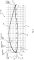
- Fig. 3 shows schematically a profile section 128 of the rotor blade 108 at a distance r from the rotor blade root 114.
- the reference numeral 132 denotes a profile chord which, as an imaginary line, connects a profile nose 130 on the front edge 120 to the rear edge 122 of the rotor blade 108.
- An arrow illustrates a flow velocity 134 which results at the profile section 128 of the rotor blade 108 at a distance r from the rotor blade root 114 from the vectorial superposition of wind speed with a peripheral speed.
- the resulting approach velocity 134 forms an approach angle 136 with the profile chord 132.
- the at least one section 148 of the rotor blade 108, in which the three pressure measuring points 138, 140 142 are arranged, is made as narrow as possible, i.e. the section 148 has the smallest possible extent in the longitudinal direction L.
- the section 148 can preferably be a single profile section 128.
- the arrangement of the at least three pressure measuring points 138, 140 142 on the suction side 124 of the rotor blade 108 takes place at a distance from the leading edge 120 with a relative profile depth t / T, which is the ratio of a position t between the leading edge 120 and the trailing edge 122 and the profile depth T of the rotor blade 108 is defined.
- a first pressure measuring point 138 is arranged at a distance of approximately 10% to 15% of the profile depth T or a relative profile depth t / T between 0.1 and 0.15 to the front edge 120.
- a second pressure measuring point 140 is arranged at a distance of approximately 10 to 30% of the profile depth T or a relative profile depth t / T between 0.1 and 0.3 from the first pressure measuring point 138.
- a third pressure measuring point 142 is in a range of approximately 10%, preferably in a range of at most 5%, of the profile depth T or a relative profile depth t / T of 0.1, in particular in a range of at most 0.05 of the relative profi depth, arranged at a distance from the rear edge 122.
- the first pressure measuring point 138 and the second pressure measuring point 140 are preferably within a range of approximately 50% of the profile depth T starting from the leading edge 120 of the rotor blade 108.
- At least three of the at least three pressure measuring points 138, 140, 142 are arranged on the suction side 124 of the rotor blade 108.
- a first differential pressure D 1 is determined between the first pressure measuring point 138 and the second pressure measuring point 140 and a second differential pressure D 2 is determined between the second pressure measuring point 140 and the third pressure measuring point 142.
- p 1 , p 2 and p 3 are the pressures measured at the respective pressure measuring points 138, 140, 142 along the profile section 128 by means of the pressure sensors of the sensor arrangement 208.
- the respective pressure coefficients c p occurring over the course of the profile of the rotor blade 108 are determined in the section 148.
- p is the static pressure measured at a point
- p ⁇ the static pressure in the flow
- ⁇ the density of the surrounding air
- v the local velocity contribution
- v ⁇ the flow velocity
- c p, 1 , c p, 2 and c p, 3 are the numerically calculated pressure coefficients at the position of the respective pressure measuring point 138, 140, 142 along the profile section 128 or section 148.
- the distribution of pressure coefficients c p over the course of the profile of the rotor blade 108 is determined on the basis of several approach velocities 134 'and approach angles 136' that are sensibly to be expected during operation of the wind energy installation 100.
- the determination of the distribution of the pressure coefficients c p, 1 , c p, 2 and c p, 3 can in particular be carried out by means of a numerical simulation.
- a suitable distribution of the pressure measuring points 138, 140, 142 in the at least one section 148 of the rotor blade 108 in the longitudinal direction L on the rotor blade surface along the profile chord 132 allows the area of the characteristic maps 144, 146 to be increased.
- the arrangement of the at least three pressure measuring points 138, 140, 142 is preferably selected such that the area of the numerically determined characteristic maps 144, 146 is maximized, whereby the susceptibility of the method to measurement inaccuracies and interpolation errors can be minimized.
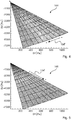
- Fig. 4 shows an example of the characteristic map 146 for the expected angle of attack 136 'at the profile section 128 or section 148.
- Fig. 5 shows the map 144 as an example for the expected flow velocities 134 'at the profile section 128.
- the differential pressures D 1 and D 2 determined after the pressure measurements have taken place form the input variables of the map 146 created for the flow velocities 134' and the map 144 created for the angle of attack 136 '.
- the flow velocity 134 and the flow angle 136 can be read out from the respective characteristic maps 144, 146.
- the angle of attack 136 ′ increases, as in FIG Fig. 4 shown.
- the flow velocity 134 ′ increases, as in FIG Fig. 5 shown.
- the arithmetic unit 214 is able to determine the flow velocity 134 and the flow angle 136 at the profile section 128 from the characteristic maps 144, 146 stored in the memory unit 216 and to set at least the blade pitch angle depending on the determined values for the flow velocity 134 and the flow angle 136 to respond to changes in the angle of attack 136.
- the adaptation of at least the blade pitch angle and / or flap deflection takes place in such a way that, taking into account the prevailing inflow situation, an optimized operation of the wind energy installation 100 is given.
- the method is preferably carried out for several sections 148 of the rotor blade 108 at different positions as seen in the longitudinal direction L.
- the sections 148 are preferably provided distributed over the entire rotor blade 108, whereby a more precise determination of the inflow situation is made possible.
- a uniform spacing of the sections 148 from one another in the longitudinal direction L of the rotor blades 108 is provided.
Landscapes
- Engineering & Computer Science (AREA)
- Life Sciences & Earth Sciences (AREA)
- Sustainable Development (AREA)
- Sustainable Energy (AREA)
- Chemical & Material Sciences (AREA)
- Combustion & Propulsion (AREA)
- Mechanical Engineering (AREA)
- General Engineering & Computer Science (AREA)
- Physics & Mathematics (AREA)
- Fluid Mechanics (AREA)
- Wind Motors (AREA)
Abstract
Description
- Die vorliegende Erfindung ein betrifft Verfahren zur Bestimmung einer den dynamischen Auftrieb beeinflussenden Anströmsituation an wenigstens einem Rotorblatt für einen Rotor einer Windenergieanlage, wobei das Rotorblatt ein Profil mit einer Profiltiefe aufweist und zwischen einer Vorderkante und einer Hinterkante des Profils eine Druckseite und eine Saugseite ausgebildet wird. Weiterhin betrifft die vorliegende Erfindung ein Rotorblatt für einen Rotor einer Windenergieanlage, eine Windenergieanlage sowie einen Windpark.
- Der Wirkungsgrad von Rotorblättern wird durch den Anströmwinkel, also dem Winkel zwischen Rotorblattprofilsehne und Anströmrichtung der Luft, bestimmt. Insbesondere bei Windenergieanlagen hängt der Anströmwinkel von der Rotorblattgeschwindigkeit -also der Rotordrehzahl- und der Windgeschwindigkeit ab. Grundsätzlich können die antreibenden Luftkräfte über die Beeinflussung des aerodynamischen Anströmwinkels am Profil des Rotorblattes durch Verkleinern der Rotorangriffsfläche oder durch eine Veränderung der effektiven Anströmgeschwindigkeit am Rotorblatt verringert werden. Eine Verkleinerung der Rotorangriffsfläche erfolgt durch eine Änderung des Rotorblatteinstellwinkels. Weiterhin beeinflusst die Anströmgeschwindigkeit den Wirkungsgrad, wobei die Anströmgeschwindigkeit von der nicht beeinflussbaren Windgeschwindigkeit und der Rotordrehzahl beeinflusst wird. Neben dem Rotorblatteinstellwinkel kann deshalb die Rotordrehzahl als Stellgröße zur Leistungsregelung herangezogen werden, sofern die Windkraftanlage eine drehzahlvariable Betriebsweise zulässt. In einer weiteren Variante kann auch eine Klappe beispielsweise im Bereich der Hinterkante genutzt werden, wobei ein Klappenwinkel der Klappe Verwendung findet, um den effektiven Anstellwinkel zu beeinflussen und somit Leistung, Lasten und/oder Schall zu regeln.
- Für eine effiziente Regelung von Rotorblatteinstellwinkel, Rotordrehzahl und/oder Klappenwinkel und damit einer effizienten Leistungsregelung, ist die Kenntnis von effektivem Anströmwinkel und Anströmgeschwindigkeit im laufenden Betrieb der Windenergieanlage von großer Bedeutung. Im Folgenden wird lediglich von einer Leistungsregelung gesprochen, wobei die Überlegungen analog auf Schall- und/oder Lastregelungen oder Kombinationen davon übertragbar sind, wobei die Wahl letztendlich von der tatsächlichen Situation abhängt.
- Das Deutsche Patent- und Markenamt hat in der Prioritätsanmeldung zu vorliegender Anmeldung folgenden Stand der Technik recherchiert:
DE 102013103150 A1 ,EP 2 148088 A1 ,WO 2006/ 039903 A1 ,WO 2015/ 185720 A1 . - Vor diesem Hintergrund war es eine Aufgabe der vorliegenden Erfindung, ein Verfahren der eingangs genannten Art weiterzubilden, welches eine effiziente Leistungs-, Lasten- und/oder Schallregelung im Betrieb der Windenergieanlage ermöglicht, aber auch ein Rotorblatt, eine Windenergieanlage sowie einen Windpark anzugeben, die einen effizienteren Betrieb ermöglichen.
- Die der Erfindung zugrundeliegende Aufgabe wird durch ein Verfahren mit den Merkmalen nach Anspruch 1 gelöst. Gemäß dem Anspruch 1 wird ein Verfahren zur Bestimmung einer den dynamischen Auftrieb beeinflussenden Anströmsituation an wenigstens einem Rotorblatt für einen Rotor einer Windenergieanlage vorgeschlagen, wobei das Rotorblatt ein Profil mit einer Profiltiefe aufweist und zwischen einer Vorderkante und einer Hinterkante des Profils eine Druckseite und eine Saugseite ausgebildet wird. Dabei wird in wenigstens einem Abschnitt des Rotorblattes in Längsrichtung an der Rotorblattoberfläche entlang einer Profilsehne des Rotorblattes an zumindest drei zueinander beabstandeten Druckmessstellen jeweils eine Druckmessung durchgeführt, wobei mittels eines numerischen Verfahrens oder durch Messungen über den Verlauf des Profils des Rotorblattes auftretende Druckbeiwerte bestimmt werden, und aufgrund der im Betrieb durchgeführten Druckmessungen und der vorab bestimmten Druckbeiwerte für die jeweilige Druckmessstelle wenigstens eine Anströmgeschwindigkeit und ein Anströmwinkel bestimmt werden.
- Durch die erfindungsgemäße Bestimmung von Anströmgeschwindigkeit und Anströmwinkel im laufenden Betrieb der Windenergieanlage lassen sich hiervon abhängige Betriebsparameter wie der Rotorblatteinstellwinkel bzw. Pitchwinkel sowie die Rotordrehzahl und/oder der Klappenwinkel einstellen, um eine effiziente Leistungs-, Lasten und/oder Schallregelung zu bewirken.
- Der wenigstens eine Abschnitt des Rotorblattes, in welchem die Druckmessungen durchgeführt wird, ist möglichst schmal gewählt, d.h. der Abschnitt weist bezogen auf eine Längsachse des Rotorblattes eine geringe axiale Erstreckung auf, innerhalb derer die Druckmessstellen im Wesentlichen fluchtend hintereinander angeordnet werden. Vorzugsweise weist der wenigstens Abschnitt eine axiale Erstreckung auf, die einem einzigen Profilschnitt entsprechen kann.
- In Kenntnis insbesondere des aktuellen Anströmwinkels, welcher den Winkel zwischen dem Rotorblatt und der im Betrieb tatsächlich anströmenden Luftströmung, also unter Berücksichtigung der Bewegung des Rotorblatts beschreibt, kann auf eine Änderung des Anströmwinkels durch eine Änderung des Rotorblatteinstellwinkels reagiert werden.
- Das numerische Verfahren zum Bestimmen der Druckbeiwerte kann während des Betriebs der Windenergieanlage oder auch alternativ oder zusätzlich vorab mittels vorab bestimmter Druckmessdaten für den Abschnitt des Rotorblattes bestimmt werden. Üblicherweise baut das numerische Verfahren auf Messwerten auf und verwendet diese. Besonders bevorzugt ist es, die Druckmessungen während des Betriebes durchzuführen und die Druckbeiwerte vorab zu bestimmen. Damit ist eine Auswertung während des Betriebes besonders einfach möglich.
- Vorzugsweise erfolgt die Durchführung der Druckmessungen und die damit verbundene Bestimmung von Anströmgeschwindigkeit und Anströmwinkel zyklisch, wobei zyklisch im Sinne einer fortlaufenden Durchführung mit konstanter, aber auch mit sich verändernder Zykluszeit zu verstehen ist. Dies erlaubt eine zeitnahe Anpassung des Blatteinstellwinkels und/oder der Rotordrehzahl, um fortlaufend auf eine sich ändernde Anströmsituation reagieren zu können.
- Dabei kann die Verteilung von Druckbeiwerten über den Verlauf des Profils anhand von mehreren im Betrieb der Windenergieanlage zu erwartenden Anströmgeschwindigkeiten und/oder Anströmwinkeln bestimmt werden, insbesondere mittels einer numerischen Simulation bestimmt werden.
- Bevorzugt können aufgrund der durchgeführten Druckmessungen und der, insbesondere numerisch, bestimmten Druckbeiwerte für die jeweilige Druckmessstelle zwei Differenzdrücke bestimmt werden, wobei die Anströmgeschwindigkeit und der Anströmwinkel basierend auf den Differenzdrücken bestimmt werden.
- Insbesondere kann ein Kennfeld für die Anströmgeschwindigkeit und ein Kennfeld für den Anströmwinkel erstellt werden, wobei die Eingangsgrößen des jeweiligen Kennfeldes die bestimmten Differenzdrücke sind. Die für die im laufenden Betrieb zur Ansteuerung von Blatteinstellwinkel und/oder Rotordrehzahl und/oder Klappenwinkel relevanten Werte für die Anströmgeschwindigkeit und den Anströmwinkel lassen sich somit einfach aus dem jeweiligen Kennfeld auslesen.
- Vorzugsweise werden die Kennfelder in dem Fall, in dem Klappen als aerodynamische Anbauteile zum Einsatz kommen, nicht für alle möglichen Klappenausschläge des Profils erstellt, sondern auf eine diskrete Anzahl an Klappenwinkel bzw. Ausschlägen, die vorzugsweise vorab festlegt sind, reduziert. Alternativ sind natürlich auch beliebig fein aufgelöste Unterteilungen der Klappenausschläge möglich.
- Dabei können zumindest drei der zumindest drei Druckmessungen auf der Saugseite des Rotorblattes durchgeführt werden, um die Anströmsituation zu bestimmen. Vorzugsweise werden insgesamt zumindest sechs Druckmessungen an unterschiedlichen Stellen durchgeführt.
- Bevorzugt kann eine erste Druckmessstelle mit einem Abstand von 5% bis 25% der Profiltiefe zur Vorderkante des Rotorblattes, vorzugsweise von etwa 10% der Profiltiefe zur Vorderkante des Rotorblattes, angeordnet werden. Die erste Druckmessstelle befindet sich vorzugsweise im Bereich des größten Unterdrucks auf der Saugseite des Rotorblattes.
- Mit dem Begriff etwa wird hier und nachfolgend ein Bereich um den Wert verstanden, der ein Intervall von höchstens 10% des Gesamtwertes umschreibt. Beispielsweise ist somit für den Wert von etwa 10% ein Bereich von 5% bis 15% der Profiltiefe zu verstehen. Vorzugsweise ist der Bereich deutlich schmaler und bezieht sich auf ein Intervall von höchstens 6%, besonders bevorzugt von höchstens 4% des Maximalwertes.
- Eine zweite Druckmessstelle kann mit einem Abstand von 10 bis 30% der Profiltiefe zu der ersten Druckmessstelle beabstandet angeordnet werden. Somit kann gewährleistet werden, dass sich eine hinreichend große Druckdifferenz zwischen der ersten Druckmessstelle und der zweiten Druckmessstelle einstellt.
- Vorzugsweise können die erste Druckmessstelle und die zweite Druckmessstelle innerhalb eines Bereiches von 50% der Profiltiefe angeordnet werden.
- Eine dritte Druckmessstelle kann in einem Bereich von 10%, vorzugsweise in einem Bereich von höchstens 5%, der Profiltiefe zur Hinterkante beabstandet angeordnet werden.
- Der gegenüber dem Abstand zwischen der ersten Druckmessstelle und der zweiten Druckmessstelle größere Abstand der dritten Druckmessstelle zur zweiten Druckmessstelle soll die geringe Druckdifferenz zwischen diesen beiden Druckmessstellen in dem hinteren Teil des Profils berücksichtigen.
- Vorteilhaft ist es, dass die Anordnung der zumindest drei Druckmessstellen derart gewählt wird, dass eine Maximierung der Fläche der Kennfelder erreicht wird. Durch die Maximierung der Fläche der Kennfelder lässt sich der Einfluss von Messungenauigkeiten und Interpolationsfehlern auf das erfindungsgemäße Verfahren minimieren.
- Bevorzugt kann das Verfahren für mehrere Abschnitte des Rotorblattes an unterschiedlichen Positionen in Längsrichtung ausgeführt werden. Insbesondere können die Abschnitte in im Wesentlichen gleichmäßigen Abständen in Längsrichtung des Rotorblattes verteilt vorgesehen werden. Auf diese Weise findet auch eine Veränderung der Anströmverhältnisse in Längsrichtung des Rotorblattes bei der Bestimmung von Anströmgeschwindigkeit und Anströmwinkel Berücksichtigung.
- Vorzugsweise sind die mehreren Abschnitte über das gesamte Rotorblatt verteilt, mindestens erstrecken sie sich über mindestens 50%, bevorzugt 75% der gesamten Rotorblattlänge. Damit ist eine besonders genaue Bestimmung der Anströmsituation entlang des gesamten Rotorblattes möglich.
- Insbesondere kann die Anordnung der Druckmessstellen an den jeweiligen Abschnitten des Rotorblattes an unterschiedlichen Positionen in Projektion auf die Profilsehne vorgesehen sein. Bevorzugt kann die Anordnung derart gewählt sein, dass die Maximierung der Fläche der Kennfelder für sämtliche Positionen der Druckmessstellen entlang des Rotorblattes erfüllt ist.
- Die eingangs gestellte Aufgabe wird weiterhin durch ein Rotorblatt für einen Rotor einer Windenergieanlage gelöst, wobei das Rotorblatt ein Profil mit einer Profiltiefe aufweist und zwischen einer Vorderkante und einer Hinterkante des Profils eine Druckseite und eine Saugseite ausgebildet ist, wobei entlang einer Profilsehne des Rotorblattes zumindest drei mit einem Abstand zueinander angeordnete Druckmessstellen vorgesehen sind, dass mittels eines numerischen Verfahrens über den Verlauf des Profils des Rotorblattes auftretende Druckbeiwerte bestimmbar sind, und dass aufgrund der durchgeführten Druckmessungen und der für die jeweilige Druckmessstelle bestimmten Druckbeiwerte zwei Differenzdrücke bestimmbar sind, mittels derer eine den dynamischen Auftrieb beeinflussende Anströmsituation an dem Rotorblatt bestimmbar ist.
- Vorzugsweise sind die an diskreten Stellen des Rotorblattes auftretenden Druckbeiwerte alternativ oder zusätzlich mittels Messungen über den Verlauf des Profils bestimmbar.
- Hierzu können zumindest drei der zumindest drei Druckmessstellen auf der Saugseite des Rotorblattes angeordnet sein.
- Dabei kann eine erste Druckmessstelle mit einem Abstand von 5% bis 25% der Profiltiefe zur Vorderkante des Rotorblattes, vorzugsweise von etwa 10% der Profiltiefe zur Vorderkante des Rotorblattes, angeordnet sein.
- Eine zweite Druckmessstelle kann mit einem Abstand von 10 bis 30% der Profiltiefe zu der ersten Druckmessstelle beabstandet angeordnet sein.
- Bevorzugt können die erste Druckmessstelle und die zweite Druckmessstelle innerhalb eines Bereiches von 50% der Profiltiefe angeordnet sein.
- Eine dritte Druckmessstelle kann in einem Bereich von 10%, vorzugsweise in einem Bereich von höchstens 5%, der Profiltiefe zur Hinterkante beabstandet angeordnet sein.
- Die Erfindung löst ferner die ihr zugrunde liegende Aufgabe bei einer Windenergieanlage, die einen aerodynamischen Rotor mit in ihrem Rotorblatteinstellwinkel verstellbaren Rotorblättern sowie eine Einrichtung zum Steuern und/oder Regeln umfasst, indem die Einrichtung dazu eingerichtet ist, zumindest die Rotorblatteinstellwinkel der Rotorblätter in Abhängigkeit von einer Anströmgeschwindigkeit und einem Anströmwinkel einzustellen, die nach einem zur Erfindung gehörenden Verfahren bestimmbar sind. Die Einrichtung zum Steuern und/oder Regeln kann ferner dazu eingerichtet sein, auch die Rotordrehzahl in Abhängigkeit von der Anströmgeschwindigkeit und dem Anströmwinkel einzustellen, die nach dem erfindungsgemäßen Verfahren bestimmbar sind. Schließlich kann die Einrichtung zum Steuern und/oder Regeln alternativ oder zusätzlich dazu eingerichtet sein, einen Klappenwinkel einer an den Rotorblättern angebrachten Klappe, insbesondere einer Hinterkantenklappe, in Abhängigkeit von der Anströmgeschwindigkeit und dem Anströmwinkel einzustellen, die nach dem erfindungsgemäßen Verfahren bestimmbar sind.
- Des Weiteren kann der Rotor der Windenergieanlage wenigstens ein nach einem gemäß der Erfindung ausgebildetes Rotorblatt aufweisen.
- Des Weiteren betrifft die Erfindung auch einen Windpark mit mehreren Windenergieanlagen, welche gemäß einer der vorstehend beschriebenen bevorzugten Ausführungsformen der Erfindung ausgebildet sind.
- Die zum erfindungsgemäßen Verfahren und zum Rotorblatt beschriebenen, bevorzugten Ausführungsformen bzw. Weiterbildungen sind zugleich auch bevorzugte Ausführungsformen der erfindungsgemäßen Windenergieanlage sowie des erfindungsgemäßen Windparks.
- Die Erfindung wird im Folgenden anhand eines möglichen Ausführungsbeispiels unter Bezugnahme auf die beigefügten Figuren näher beschrieben. Hierbei zeigen:
- Fig. 1
- zeigt schematisch eine Windenergieanlage in einer perspektivischen Darstellung;
- Fig. 2
- schematisch und exemplarisch ein Rotorblatt einer Windenergieanlage;
- Fig. 3
- schematisch und exemplarisch einen Profilschnitt eines Rotorblattes;
- Fig. 4
- exemplarisch ein Kennfeld für einen Anströmwinkel am Profilschnitt;
- Fig. 5
- exemplarisch ein Kennfeld für eine Anströmgeschwindigkeit am Profilschnitt.
-
Fig. 1 zeigt eine schematische Darstellung einer Windenergieanlage 100 gemäß der Erfindung. Die Windenergieanlage 100 weist einen Turm 102 und eine Gondel 104 auf dem Turm 102 auf. An der Gondel 104 ist ein aerodynamischer Rotor 106 mit drei Rotorblättern 108 und einem Spinner 110 vorgesehen. Der aerodynamische Rotor 106 wird im Betrieb der Windenergieanlage 100 durch den Wind in eine Drehbewegung versetzt und dreht somit auch einen elektrodynamischen Rotor oder Läufer eines Generators, welcher direkt oder indirekt mit dem aerodynamischen Rotor 106 gekoppelt ist. Der elektrische Generator ist in der Gondel 104 angeordnet und erzeugt elektrische Energie. Die Pitchwinkel der Rotorblätter 108 können durch Pitchmotoren an den Rotorblattwurzeln der jeweiligen Rotorblätter 108 verändert werden. - Die Windenergieanlage 100 ist vorliegend mit einer Einrichtung 200 zum Steuern und/oder Regeln ausgestaltet. Mittels der Einrichtung 200 wird eine Stelleinrichtung mit entsprechender Aktorik 202, 204, 206 für beispielsweise die Rotorblätter 108 angesteuert. Die Aktorik 202, 204, 206 ist beispielsweise in den Rotorblättern 108 angeordnet gezeigt, kann in anderen Ausführungen aber auch an anderen Stellen, insbesondere innerhalb des Spinners 110 als Teil der Rotornabe, ausgebildet sein. Die Aktorik kann einen Einstellwinkel der Rotorblätter 108, genannt Pitchwinkel, verändern. Alternativ oder zusätzlich kann die Stelleinrichtung auch an den Rotorblättern 108 angeordnete aerodynamische Anbauteile, insbesondere Klappen wie Hinterkantenklappen, ansteuern und beispielsweise den Klappenwinkel kontrollieren. Auch kann die Einrichtung 200 eine Rotordrehzahl steuern.
- Die Einrichtung 200 erhält Messinformationen von zumindest einer Sensoranordnung 208 mit zumindest drei Drucksensoren, welche an ein Messmodul 210 der Einrichtung 200 gehen. Die drei Drucksensoren der zumindest einen Sensoranordnung 208 sind an einem Abschnitt 148 des Rotorblattes 108 angeordnet. Das Messmodul 210 hat eine Ermittlungseinheit 212 zur Ermittlung von Drücken p1, p2, p3, die an drei Druckmessstellen auftreten. Eine Recheneinheit 214 bestimmt anhand der ermittelten Drücke p1, p2, p3 zwei Druckdifferenzen D1, D2.
- Der Recheneinheit 214 ist eine Speichereinheit 216 zugeordnet. Es können auch an zwei oder allen Rotorblättern 108 zumindest eine Sensoranordnung 208 mit zumindest drei Drucksensoren angeordnet sein. Insbesondere können an einem Rotorblatt 108 mehrere Sensoranordnungen 208 angebracht sein. Diese können gleichmäßig beabstandet zueinander in Längsrichtung L des Rotorblattes 108 verteilt angeordnet sein. Ebenso sind natürlich auch unterschiedliche Abstände in Längsrichtung L vorgesehen sein, wobei diese durch die Recheneinheit 214 angemessen berücksichtig werden.
-
Fig. 2 zeigt eine schematische Ansicht eines einzelnen Rotorblattes 108 mit einer Vorderkante 120 sowie einer Hinterkante 122. Abgebildet ist eine Draufsicht auf eine Saugseite 124 des Rotorblattes 108, die gegenüberliegende Druckseite 126 ist in der Ansicht nicht sichtbar. - Das Rotorblatt 108 weist eine Rotorblattwurzel 114 und eine Rotorblattspitze 116 auf. Die Länge zwischen der Rotorblattwurzel 114 und der Rotorblattspitze 116 wird als Rotorblattlänge R entlang einer Längsrichtung L bezeichnet. Der Abstand zwischen der Vorderkante 120 und der Hinterkante 122 des Rotorblattes108 wird als Profiltiefe T bezeichnet. An der Rotorblattwurzel 114 oder im Allgemeinen in dem Bereich nahe der Rotorblattwurzel 114 weist das Rotorblatt 108 eine große Profiltiefe T auf. An der Rotorblattspitze 116 ist die Profiltiefe T dagegen sehr viel kleiner.
-
Fig. 3 zeigt schematisch einen Profilschnitt 128 des Rotorblattes 108 in einem Abstand r zur Rotorblattwurzel 114. Mit dem Bezugszeichen 132 ist eine Profilsehne bezeichnet, welche als gedachte Linie eine Profilnase 130 an der der Vorderkante 120 mit der Hinterkante 122 des Rotorblattes 108 verbindet. Ein Pfeil veranschaulicht eine Anströmgeschwindigkeit 134, die an dem Profilschnitt 128 des Rotorblattes 108 im Abstand r zur Rotorblattwurzel 114 aus der vektoriellen Überlagerung von Windgeschwindigkeit mit einer Umfangsgeschwindigkeit resultiert. Die sich ergebende Anströmgeschwindigkeit 134 bildet mit der Profilsehne 132 einen Anströmwinkel 136. - Zur Bestimmung einer den dynamischen Auftrieb beeinflussenden Anströmsituation an dem Rotorblatt 108 ist vorgesehen, dass in wenigstens einem schmalen, insbesondere streifenförmigen oder linienförmigen, Abschnitt 148 des Rotorblattes 108 in Längsrichtung L an der Rotorblattoberfläche entlang der Profilsehne 132 an zumindest drei zueinander beabstandeten Druckmessstellen 138, 140 142 jeweils eine Druckmessung durchgeführt wird. Der wenigstens eine Abschnitt 148 des Rotorblattes 108, in welchem die drei Druckmessstellen 138, 140 142 angeordnet werden, ist möglichst schmal ausgeführt, d.h. der Abschnitt 148 hat eine möglichst geringe Erstreckung in Längsrichtung L. Vorzugsweise kann der Abschnitt 148 als ein einziger Profilschnitt 128 sein.
- Die Anordnung der zumindest drei Druckmessstellen 138, 140 142 auf der Saugseite 124 des Rotorblattes 108 erfolgt jeweils in einem Abstand zur Vorderkante 120 mit einer relativen Profiltiefe t/T, die als Verhältnis einer Position t zwischen der Vorderkante 120 und der Hinterkante 122 und der Profiltiefe T des Rotorblattes 108 definiert ist. Dabei ist eine erste Druckmessstelle 138 mit einem Abstand von etwa 10% bis 15% der Profiltiefe T bzw. einer relativen Profiltiefe t/T zwischen 0,1 und 0,15 zur Vorderkante 120 angeordnet. Eine zweite Druckmessstelle 140 ist mit einem Abstand von etwa 10 bis 30% der Profiltiefe T bzw. einer relativen Profiltiefe t/T zwischen 0,1 und 0,3 zu der ersten Druckmessstelle 138 beabstandet angeordnet. Eine dritte Druckmessstelle 142 ist in einem Bereich von etwa 10%, vorzugsweise in einem Bereich von höchstens 5%, der Profiltiefe T bzw. einer relativen Profiltiefe t/T von0,1, insbesondere in einem Bereich von höchstens 0,05 der relativen Profitiefe, zur Hinterkante 122 beabstandet angeordnet. Die erste Druckmessstelle 138 und die zweite Druckmessstelle 140 werden vorzugsweise innerhalb eines Bereiches von etwa 50% der Profiltiefe T ausgehend von der Vorderkante 120 des Rotorblattes 108 angeordnet. Zumindest drei der zumindest drei Druckmessstellen 138, 140, 142 sind auf der Saugseite 124 des Rotorblattes 108 angeordnet.
- Mit Hilfe der zumindest drei auf dem Abschnitt 148 des Rotorblattes 108 angeordneten Druckmessstellen 138, 140, 142 soll die den dynamischen Auftrieb im laufenden Betrieb der Windenergieanlage 100 beeinflussende Anströmsituation, d.h. die Anströmgeschwindigkeit 134 und der Anströmwinkel 136, bestimmt werden. Hierzu werden zwischen der ersten Druckmessstelle 138 und zweiten Druckmessstelle 140 ein erster Differenzdruck D1 und zwischen der zweiten Druckmessstelle 140 und der dritten Druckmessstelle 142 ein zweiter Differenzdruck D2 bestimmt. Die Differenzdrücke D1 und D2 bestimmen sich wie folgt:

- Darin sind p1, p2 und p3 die an den jeweiligen Druckmessstellen 138, 140, 142 entlang des Profilschnitts 128 mittels der Drucksensoren der Sensoranordnung 208 gemessenen Drücke.
- Mittels eines numerischen Verfahrens zur Profilsimulation des Rotorblattes 108, beispielsweise dem Programm "xfoil", werden die jeweiligen über den Verlauf des Profils des Rotorblattes 108 auftretenden Druckbeiwerte cp in dem Abschnitt 148 bestimmt. Der Druckbeiwert cp ist folgendermaßen definiert:

- Darin sind p der an einem Punkt gemessene statisch Druck, p∞ der statische Druck in der Anströmung, ρ die Dichte der umgebenden Luft, v der lokale Geschwindigkeitsbeitrag und v∞ die Anströmgeschwindigkeit.
- Somit lässt sich der Druck p wie folgt berechnen:

- Aus den Gleichungen (1) und (3) ergibt sich:


- Darin sind cp,1, cp,2 und cp,3 die jeweils numerisch berechneten Druckbeiwerte an der Position der jeweiligen Druckmessstelle 138,140, 142 entlang des Profilschnittes 128 bzw. Abschnitts148.
- Die Verteilung von Druckbeiwerten cp über den Verlauf des Profils des Rotorblattes 108 wird anhand von mehreren im Betrieb der Windenergieanlage 100 sinnvollerweise zu erwartenden Anströmgeschwindigkeiten 134' und Anströmwinkeln 136' bestimmt. Die Bestimmung der Verteilung der Druckbeiwerte cp,1, cp,2 und cp,3 kann insbesondere mittels einer numerischen Simulation durchgeführt werden. Durch die Simulation der Verteilung der Druckbeiwerte cp,1, cp,2 und cp,3 für eine Reihe von im Betrieb der Windenergieanlage 100 sinnvollerweise zu erwartender Anströmgeschwindigkeiten 134' und Anströmwinkel 136' und unter Anwendung der weiter oben stehenden Relationen gemäß den Gleichungen (4) und (5) ergeben sich für die zu erwartenden Anströmgeschwindigkeiten 134' und die zu erwartenden Anströmwinkel136' jeweils ein in der Speichereinheit 216 hinterlegbares Kennfeld 144, 146, wie sie in den
Fig. 4 und 5 beispielhaft dargestellt sind, aus denen die zu bestimmenden Größen Anströmgeschwindigkeit 134 und Anströmwinkel 136 nach Durchführung der Druckmessungen in den zumindest drei Druckmessstellen 138,140, 142 und anschließend erfolgter Bestimmung der Differenzdrücke D1 und D2 ermittelt werden können. - Durch eine geeignete Verteilung der Druckmessstellen 138,140, 142 in dem wenigstens einen Abschnitt 148 des Rotorblattes 108 in Längsrichtung L an der Rotorblattoberfläche entlang der Profilsehne 132 lässt sich die Fläche der Kennfelder 144, 146 vergrößern. Die Anordnung der zumindest drei Druckmessstellen 138, 140, 142 wird bevorzugt derart gewählt, dass eine Maximierung der Fläche der numerisch bestimmten Kennfelder 144, 146 erreicht wird, wodurch die Anfälligkeit des Verfahrens für Messungenauigkeiten und Interpolationsfehler minimiert werden kann.
-
Fig. 4 zeigt exemplarisch das Kennfeld 146 für die zu erwartenden Anströmwinkel 136' an dem Profilschnitt 128 respektive Abschnitt 148.Fig. 5 zeigt exemplarisch das Kennfeld 144 für die zu erwartenden Anströmgeschwindigkeiten 134' an dem Profilschnitt 128. Die nach den erfolgten Druckmessungen bestimmten Differenzdrücke D1 und D2 bilden die Eingangsgrößen des erstellten Kennfeldes 146 für die Anströmgeschwindigkeiten 134' und des erstellten Kennfeldes 144 für die Anströmwinkel 136'. Aus den jeweiligen Kennfeldern 144, 146 lassen sich nach erfolgter Bestimmung der Differenzdrücke D1, D2 die Anströmgeschwindigkeit 134 und der Anströmwinkel 136 auslesen. Mit abnehmenden Differenzdruck D1 und abnehmendem Differenzdruck D2 nimmt der Anströmwinkel 136' zu, wie inFig. 4 dargestellt. Mit zunehmenden Differenzdruck D1 und abnehmendem Differenzdruck D2 nimmt die Anströmgeschwindigkeit 134' zu, wie inFig. 5 dargestellt. - Die Recheneinheit 214 ist in der Lage, aus den in der Speichereinheit 216 hinterlegbaren Kennfeldern 144, 146 die Anströmgeschwindigkeit 134 und den Anströmwinkel 136 am Profilschnitt 128 zu bestimmen und in Abhängigkeit von den bestimmten Werten für die Anströmgeschwindigkeit 134 und den Anströmwinkel 136 zumindest den Blatteinstellwinkel einzustellen, um auf Änderungen des Anströmwinkels 136 zu reagieren. Die Anpassung zumindest des Blatteinstellwinkels und/oder Klappenausschlags erfolgt in der Weise, dass unter Berücksichtigung der herrschenden Anströmsituation ein optimierter Betrieb der Windenergieanlage 100 gegeben ist.
- Das Verfahren wird vorzugsweise für mehrere Abschnitte 148 des Rotorblattes 108 an in Längsrichtung L gesehen unterschiedlichen Positionen ausgeführt. Vorzugsweise sind die Abschnitte 148 über das gesamte Rotorblatt 108 verteilt vorgesehen, wodurch eine exaktere Bestimmung der Anströmsituation ermöglicht wird. Insbesondere ist eine gleichmäßige Beabstandung der Abschnitte 148 zueinander in Längsrichtung L der Rotorblattes 108 vorgesehen.
Claims (15)
- Verfahren zur Bestimmung einer den dynamischen Auftrieb beeinflussenden Anströmsituation an wenigstens einem Rotorblatt (108) für einen Rotor (106) einer Windenergieanlage (100), wobei das Rotorblatt (108) ein Profil mit einer Profiltiefe (T) aufweist und zwischen einer Vorderkante (120) und einer Hinterkante (122) des Profils eine Druckseite (126) und eine Saugseite (124) ausgebildet wird, dadurch gekennzeichnet, dass in wenigstens einem Abschnitt (148) des Rotorblattes (108) in Längsrichtung (L) an der Rotorblattoberfläche entlang einer Profilsehne (132) des Rotorblattes (108) an zumindest drei zueinander beabstandeten Druckmessstellen (138, 140, 142) jeweils eine Druckmessung durchgeführt wird, dass mittels eines numerischen Verfahrens oder durch Messungen über den Verlauf des Profils des Rotorblattes (108) auftretende Druckbeiwerte (cp1, cp2, cp3) bestimmt werden, und dass aufgrund der durchgeführten Druckmessungen und der bestimmten Druckbeiwerte (cp1, cp2, cp3) für die jeweilige Druckmessstelle (138, 140, 142) wenigstens eine Anströmgeschwindigkeit (134) und ein Anströmwinkel (136) bestimmt werden.
- Verfahren nach Anspruch 1, dadurch gekennzeichnet, dass die Verteilung von Druckbeiwerten (cp1, cp2, cp3) über den Verlauf des Profils anhand von mehreren im Betrieb der Windenergieanlage (100) zu erwartenden Anströmgeschwindigkeiten (134') und/oder Anströmwinkeln (136') bestimmt wird, insbesondere mittels einer numerischen Simulation bestimmt wird.
- Verfahren nach Anspruch 1 oder 2, wobei aufgrund der durchgeführten Druckmessungen und der bestimmten Druckbeiwerte (cp1, cp2, cp3) für die jeweilige Druckmessstelle (138, 140, 142) zwei Differenzdrücke (D1, D2) bestimmt werden, wobei die Anströmgeschwindigkeit (134) und der Anströmwinkel (136) basierend auf den Differenzdrücken (D1, D2) bestimmt werden.
- Verfahren nach Anspruch 3, dadurch gekennzeichnet, dass ein Kennfeld (146) für die Anströmgeschwindigkeit (134') und ein Kennfeld (144) für den Anströmwinkel (136') erstellt werden, wobei die Eingangsgrößen des jeweiligen Kennfeldes (144, 146) die bestimmten Differenzdrücke (D1, D2) sind.
- Verfahren nach einem der vorstehenden Ansprüche, dadurch gekennzeichnet, dass zumindest drei der zumindest drei Druckmessungen auf der Saugseite (124) des Rotorblattes (108) durchgeführt werden.
- Verfahren nach einem der vorstehenden Ansprüche, dadurch gekennzeichnet, dass eine erste Druckmessstelle (138) mit einem Abstand von 5% bis 25% der Profiltiefe (T) zur Vorderkante (120) des Rotorblattes (108) angeordnet wird.
- Verfahren nach Anspruch 6, dadurch gekennzeichnet, dass eine zweite Druckmessstelle (140) mit einem Abstand von 10 bis 30% der Profiltiefe (T) zu der ersten Druckmessstelle (138) beabstandet angeordnet wird, wobei insbesondere die erste Druckmessstelle (138) und die zweite Druckmessstelle (140) innerhalb eines Bereiches von 50% der Profiltiefe (T) angeordnet werden.
- Verfahren nach einem der Ansprüche 6 oder 7, dadurch gekennzeichnet, dass eine dritte Druckmessstelle (142) in einem Bereich von 10%, vorzugsweise in einem Bereich von höchstens 5%, der Profiltiefe (T) zur Hinterkante (122) beabstandet angeordnet wird.
- Verfahren nach einem der Ansprüche 7 oder 8, dadurch gekennzeichnet, dass die Anordnung der zumindest drei Druckmessstellen (138, 140, 142) derart gewählt wird, dass eine Maximierung der Fläche der Kennfelder (144, 146) erreicht wird.
- Verfahren nach einem der vorstehenden Ansprüche, dadurch gekennzeichnet, dass das Verfahren für mehrere Abschnitte (148) des Rotorblattes (108) an unterschiedlichen Positionen in Längsrichtung (L) ausgeführt wird, wobei die Anordnung der Druckmessstellen (138, 140, 142) insbesondere an den jeweiligen Abschnitten (148) des Rotorblattes (108) an unterschiedlichen Positionen in Projektion auf die Profilsehne (132) vorgesehen ist.
- Rotorblatt (108) für einen Rotor (106) einer Windenergieanlage (100), wobei das Rotorblatt (108) ein Profil mit einer Profiltiefe (T) aufweist und zwischen einer Vorderkante (120) und einer Hinterkante (122) des Profils eine Druckseite (126) und eine Saugseite (124) ausgebildet ist, dadurch gekennzeichnet, dass entlang einer Profilsehne (138) des Rotorblattes (108) zumindest drei mit einem Abstand zueinander angeordnete Druckmessstellen (138, 140, 142) vorgesehen sind, dass mittels eines numerischen Verfahrens über den Verlauf des Profils des Rotorblattes auftretende Druckbeiwerte (cp1, cp2, cp3) bestimmbar sind, und dass aufgrund der durchgeführten Druckmessungen und der für die jeweilige Druckmessstelle bestimmten Druckbeiwerte (cp1, cp2, cp3) zwei Differenzdrücke (D1, D2) bestimmbar sind, mittels derer eine den dynamischen Auftrieb beeinflussende Anströmsituation an dem Rotorblatt (108) bestimmbar ist.
- Rotorblatt (108) nach Anspruch 11, dadurch gekennzeichnet, dass zumindest drei der zumindest drei Druckmessstellen (138, 140, 142) auf der Saugseite (124) des Rotorblattes (108) angeordnet sind.
- Windenergieanlage (108), umfassend einen aerodynamischen Rotor (106) mit in ihrem Blattwinkel verstellbaren Rotorblättern (108) sowie einer Einrichtung (200) zum Steuern und/oder Regeln, dadurch gekennzeichnet, dass die Einrichtung (200) dazu eingerichtet ist, zumindest die Rotorblatteinstellwinkel der Rotorblätter (108) in Abhängigkeit von einer Anströmgeschwindigkeit (134) und einem Anströmwinkel (136) einzustellen, die nach einem Verfahren gemäß wenigstens einem der Ansprüche 1 bis 10 bestimmbar sind.
- Windenergieanlage (100) nach Anspruch 13, dadurch gekennzeichnet, dass der Rotor (106) wenigstens ein Rotorblatt (108) aufweist, das nach einem der vorstehenden Ansprüche 11 bis 12 ausgebildet ist.
- Windpark mit mehreren Windenergieanlagen (100) nach Anspruch 13 oder 14.
Applications Claiming Priority (1)
| Application Number | Priority Date | Filing Date | Title |
|---|---|---|---|
| DE102019107966.7A DE102019107966A1 (de) | 2019-03-28 | 2019-03-28 | Verfahren zur Bestimmung einer den dynamischen Auftrieb beeinflussenden Anströmsituation an wenigstens einem Rotorblatt |
Publications (2)
| Publication Number | Publication Date |
|---|---|
| EP3715627A1 true EP3715627A1 (de) | 2020-09-30 |
| EP3715627B1 EP3715627B1 (de) | 2023-01-04 |
Family
ID=69960397
Family Applications (1)
| Application Number | Title | Priority Date | Filing Date |
|---|---|---|---|
| EP20165200.5A Active EP3715627B1 (de) | 2019-03-28 | 2020-03-24 | Verfahren zur bestimmung einer den dynamischen auftrieb beeinflussenden anströmsituation an wenigstens einem rotorblatt |
Country Status (2)
| Country | Link |
|---|---|
| EP (1) | EP3715627B1 (de) |
| DE (1) | DE102019107966A1 (de) |
Cited By (1)
| Publication number | Priority date | Publication date | Assignee | Title |
|---|---|---|---|---|
| WO2024109027A1 (zh) * | 2022-11-22 | 2024-05-30 | 中材科技风电叶片股份有限公司 | 风电机组、风电叶片及风电叶片截面翼型的失速监测方法 |
Citations (5)
| Publication number | Priority date | Publication date | Assignee | Title |
|---|---|---|---|---|
| WO2006039903A1 (de) | 2004-10-09 | 2006-04-20 | Igus - Innovative Technische Systeme Gmbh | Verfahren und einrichtung zur steuerung der pitchwinkel der rotorblätter von windkraftanlagen |
| EP2148088A1 (de) | 2008-07-22 | 2010-01-27 | Siemens Aktiengesellschaft | Verfahren und Anordnung zur Anpassung des Anstellwinkels der Windturbinenblätter |
| WO2012122669A1 (en) * | 2011-03-14 | 2012-09-20 | General Electric Company | Wind turbine blades with air pressure sensors |
| DE102013103150A1 (de) | 2013-03-27 | 2014-10-02 | Deutsches Zentrum für Luft- und Raumfahrt e.V. | Verfahren zum Ermitteln eines Anstellwinkels |
| WO2015185720A1 (de) | 2014-06-06 | 2015-12-10 | Wobben Properties Gmbh | Windenergieanlage mit optischen drucksensoren sowie verfahren zum betreiben einer windenergieanlage |
-
2019
- 2019-03-28 DE DE102019107966.7A patent/DE102019107966A1/de not_active Withdrawn
-
2020
- 2020-03-24 EP EP20165200.5A patent/EP3715627B1/de active Active
Patent Citations (5)
| Publication number | Priority date | Publication date | Assignee | Title |
|---|---|---|---|---|
| WO2006039903A1 (de) | 2004-10-09 | 2006-04-20 | Igus - Innovative Technische Systeme Gmbh | Verfahren und einrichtung zur steuerung der pitchwinkel der rotorblätter von windkraftanlagen |
| EP2148088A1 (de) | 2008-07-22 | 2010-01-27 | Siemens Aktiengesellschaft | Verfahren und Anordnung zur Anpassung des Anstellwinkels der Windturbinenblätter |
| WO2012122669A1 (en) * | 2011-03-14 | 2012-09-20 | General Electric Company | Wind turbine blades with air pressure sensors |
| DE102013103150A1 (de) | 2013-03-27 | 2014-10-02 | Deutsches Zentrum für Luft- und Raumfahrt e.V. | Verfahren zum Ermitteln eines Anstellwinkels |
| WO2015185720A1 (de) | 2014-06-06 | 2015-12-10 | Wobben Properties Gmbh | Windenergieanlage mit optischen drucksensoren sowie verfahren zum betreiben einer windenergieanlage |
Cited By (1)
| Publication number | Priority date | Publication date | Assignee | Title |
|---|---|---|---|---|
| WO2024109027A1 (zh) * | 2022-11-22 | 2024-05-30 | 中材科技风电叶片股份有限公司 | 风电机组、风电叶片及风电叶片截面翼型的失速监测方法 |
Also Published As
| Publication number | Publication date |
|---|---|
| DE102019107966A1 (de) | 2020-10-01 |
| EP3715627B1 (de) | 2023-01-04 |
Similar Documents
| Publication | Publication Date | Title |
|---|---|---|
| EP2929178B1 (de) | Rotorblatthinterkante | |
| EP2145103B1 (de) | Verfahren zum betrieb eines windparks mit einer mehrzahl von windkraftanlagen | |
| EP2582972B1 (de) | Verfahren und vorrichtung zur verhinderung einer querschwingung einer windenergieanlage | |
| EP2225461B1 (de) | Verfahren zum betreiben einer windenergieanlage | |
| EP3527816B1 (de) | Verfahren und system zum ermitteln einer ausrichtungskorrekturfunktion | |
| DE112012005771T5 (de) | Windkraftanlage und Verfahren zum Bestimmen von Windkraftanlagenparametern | |
| DE102012210150A1 (de) | Windenergieanlage und Verfahren zum Steuern einer Windenergieanlage oder eines Windparks | |
| EP3735532A1 (de) | Betreiben einer windenergieanlage bei sturm | |
| EP3421784A1 (de) | Verfahren zum betreiben einer windenergieanlage | |
| DE3727992A1 (de) | Flugzeug-schubregelung | |
| EP3402981B1 (de) | Verfahren zum bewerten einer anströmung an einem rotorblatt einer windenergieanlage sowie verfahren zum steuern einer windenergieanlage und windenergieanlage | |
| EP3152438A1 (de) | Windenergieanlage mit optischen drucksensoren sowie verfahren zum betreiben einer windenergieanlage | |
| WO2020064925A1 (de) | Verfahren zum betreiben einer windenergieanlage, windenergieanlage und windpark | |
| EP3775536A1 (de) | Windenergieanlage, windpark sowie verfahren zum regeln einer windenergieanlage und eines windparks | |
| EP3555461B1 (de) | Verfahren zum betrieb einer windenergieanlage sowie einrichtung zum steuern und/oder regeln einer windenergieanlage und entsprechende windenergieanlage mit einem rotor und einem über den rotor angetriebenen generator zur erzeugung einer elektrischen leistung | |
| EP4227523B1 (de) | Verfahren zum betrieb eines windparks, windenergieanlage und windpark | |
| DE3727991A1 (de) | Flugzeug-schubregelung | |
| EP3715627B1 (de) | Verfahren zur bestimmung einer den dynamischen auftrieb beeinflussenden anströmsituation an wenigstens einem rotorblatt | |
| WO2019138132A1 (de) | Verfahren zum steuern einer windenergieanlage und windenergieanlage | |
| DE102011075337A1 (de) | Verfahren und Vorrichtung zur Ansteuerung einer Anlage | |
| WO2016149718A1 (de) | Verfahren zur ermittlung eines gierwinkelfehlers bei einer windkraftanlage | |
| EP3839249B1 (de) | Verfahren zum einstellen eines pitchwinkels eines rotorblatts, steuerungsvorrichtung zum einstellen eines pitchwinkels sowie dazugehörige windenergieanlage | |
| EP3587805B1 (de) | System zur ermittlung der verfügbaren leistung eines windparks | |
| DE102018008391A1 (de) | Steuerung einer Windenegaieanlage | |
| EP3844385B1 (de) | Rotorblatt für eine windenergieanlage und windenergieanlage |
Legal Events
| Date | Code | Title | Description |
|---|---|---|---|
| PUAI | Public reference made under article 153(3) epc to a published international application that has entered the european phase |
Free format text: ORIGINAL CODE: 0009012 |
|
| STAA | Information on the status of an ep patent application or granted ep patent |
Free format text: STATUS: THE APPLICATION HAS BEEN PUBLISHED |
|
| AK | Designated contracting states |
Kind code of ref document: A1 Designated state(s): AL AT BE BG CH CY CZ DE DK EE ES FI FR GB GR HR HU IE IS IT LI LT LU LV MC MK MT NL NO PL PT RO RS SE SI SK SM TR |
|
| AX | Request for extension of the european patent |
Extension state: BA ME |
|
| STAA | Information on the status of an ep patent application or granted ep patent |
Free format text: STATUS: REQUEST FOR EXAMINATION WAS MADE |
|
| 17P | Request for examination filed |
Effective date: 20210330 |
|
| RBV | Designated contracting states (corrected) |
Designated state(s): AL AT BE BG CH CY CZ DE DK EE ES FI FR GB GR HR HU IE IS IT LI LT LU LV MC MK MT NL NO PL PT RO RS SE SI SK SM TR |
|
| GRAP | Despatch of communication of intention to grant a patent |
Free format text: ORIGINAL CODE: EPIDOSNIGR1 |
|
| STAA | Information on the status of an ep patent application or granted ep patent |
Free format text: STATUS: GRANT OF PATENT IS INTENDED |
|
| INTG | Intention to grant announced |
Effective date: 20220812 |
|
| GRAS | Grant fee paid |
Free format text: ORIGINAL CODE: EPIDOSNIGR3 |
|
| GRAA | (expected) grant |
Free format text: ORIGINAL CODE: 0009210 |
|
| STAA | Information on the status of an ep patent application or granted ep patent |
Free format text: STATUS: THE PATENT HAS BEEN GRANTED |
|
| AK | Designated contracting states |
Kind code of ref document: B1 Designated state(s): AL AT BE BG CH CY CZ DE DK EE ES FI FR GB GR HR HU IE IS IT LI LT LU LV MC MK MT NL NO PL PT RO RS SE SI SK SM TR |
|
| REG | Reference to a national code |
Ref country code: GB Ref legal event code: FG4D Free format text: NOT ENGLISH |
|
| REG | Reference to a national code |
Ref country code: CH Ref legal event code: EP |
|
| REG | Reference to a national code |
Ref country code: AT Ref legal event code: REF Ref document number: 1542106 Country of ref document: AT Kind code of ref document: T Effective date: 20230115 |
|
| REG | Reference to a national code |
Ref country code: DE Ref legal event code: R096 Ref document number: 502020002293 Country of ref document: DE |
|
| REG | Reference to a national code |
Ref country code: IE Ref legal event code: FG4D Free format text: LANGUAGE OF EP DOCUMENT: GERMAN |
|
| REG | Reference to a national code |
Ref country code: LT Ref legal event code: MG9D |
|
| REG | Reference to a national code |
Ref country code: NL Ref legal event code: MP Effective date: 20230104 |
|
| PG25 | Lapsed in a contracting state [announced via postgrant information from national office to epo] |
Ref country code: NL Free format text: LAPSE BECAUSE OF FAILURE TO SUBMIT A TRANSLATION OF THE DESCRIPTION OR TO PAY THE FEE WITHIN THE PRESCRIBED TIME-LIMIT Effective date: 20230104 |
|
| PG25 | Lapsed in a contracting state [announced via postgrant information from national office to epo] |
Ref country code: RS Free format text: LAPSE BECAUSE OF FAILURE TO SUBMIT A TRANSLATION OF THE DESCRIPTION OR TO PAY THE FEE WITHIN THE PRESCRIBED TIME-LIMIT Effective date: 20230104 Ref country code: PT Free format text: LAPSE BECAUSE OF FAILURE TO SUBMIT A TRANSLATION OF THE DESCRIPTION OR TO PAY THE FEE WITHIN THE PRESCRIBED TIME-LIMIT Effective date: 20230504 Ref country code: NO Free format text: LAPSE BECAUSE OF FAILURE TO SUBMIT A TRANSLATION OF THE DESCRIPTION OR TO PAY THE FEE WITHIN THE PRESCRIBED TIME-LIMIT Effective date: 20230404 Ref country code: LV Free format text: LAPSE BECAUSE OF FAILURE TO SUBMIT A TRANSLATION OF THE DESCRIPTION OR TO PAY THE FEE WITHIN THE PRESCRIBED TIME-LIMIT Effective date: 20230104 Ref country code: LT Free format text: LAPSE BECAUSE OF FAILURE TO SUBMIT A TRANSLATION OF THE DESCRIPTION OR TO PAY THE FEE WITHIN THE PRESCRIBED TIME-LIMIT Effective date: 20230104 Ref country code: HR Free format text: LAPSE BECAUSE OF FAILURE TO SUBMIT A TRANSLATION OF THE DESCRIPTION OR TO PAY THE FEE WITHIN THE PRESCRIBED TIME-LIMIT Effective date: 20230104 Ref country code: ES Free format text: LAPSE BECAUSE OF FAILURE TO SUBMIT A TRANSLATION OF THE DESCRIPTION OR TO PAY THE FEE WITHIN THE PRESCRIBED TIME-LIMIT Effective date: 20230104 |
|
| PG25 | Lapsed in a contracting state [announced via postgrant information from national office to epo] |
Ref country code: SE Free format text: LAPSE BECAUSE OF FAILURE TO SUBMIT A TRANSLATION OF THE DESCRIPTION OR TO PAY THE FEE WITHIN THE PRESCRIBED TIME-LIMIT Effective date: 20230104 Ref country code: PL Free format text: LAPSE BECAUSE OF FAILURE TO SUBMIT A TRANSLATION OF THE DESCRIPTION OR TO PAY THE FEE WITHIN THE PRESCRIBED TIME-LIMIT Effective date: 20230104 Ref country code: IS Free format text: LAPSE BECAUSE OF FAILURE TO SUBMIT A TRANSLATION OF THE DESCRIPTION OR TO PAY THE FEE WITHIN THE PRESCRIBED TIME-LIMIT Effective date: 20230504 Ref country code: GR Free format text: LAPSE BECAUSE OF FAILURE TO SUBMIT A TRANSLATION OF THE DESCRIPTION OR TO PAY THE FEE WITHIN THE PRESCRIBED TIME-LIMIT Effective date: 20230405 Ref country code: FI Free format text: LAPSE BECAUSE OF FAILURE TO SUBMIT A TRANSLATION OF THE DESCRIPTION OR TO PAY THE FEE WITHIN THE PRESCRIBED TIME-LIMIT Effective date: 20230104 |
|
| REG | Reference to a national code |
Ref country code: DE Ref legal event code: R097 Ref document number: 502020002293 Country of ref document: DE |
|
| PG25 | Lapsed in a contracting state [announced via postgrant information from national office to epo] |
Ref country code: SM Free format text: LAPSE BECAUSE OF FAILURE TO SUBMIT A TRANSLATION OF THE DESCRIPTION OR TO PAY THE FEE WITHIN THE PRESCRIBED TIME-LIMIT Effective date: 20230104 Ref country code: RO Free format text: LAPSE BECAUSE OF FAILURE TO SUBMIT A TRANSLATION OF THE DESCRIPTION OR TO PAY THE FEE WITHIN THE PRESCRIBED TIME-LIMIT Effective date: 20230104 Ref country code: MC Free format text: LAPSE BECAUSE OF FAILURE TO SUBMIT A TRANSLATION OF THE DESCRIPTION OR TO PAY THE FEE WITHIN THE PRESCRIBED TIME-LIMIT Effective date: 20230104 Ref country code: EE Free format text: LAPSE BECAUSE OF FAILURE TO SUBMIT A TRANSLATION OF THE DESCRIPTION OR TO PAY THE FEE WITHIN THE PRESCRIBED TIME-LIMIT Effective date: 20230104 Ref country code: DK Free format text: LAPSE BECAUSE OF FAILURE TO SUBMIT A TRANSLATION OF THE DESCRIPTION OR TO PAY THE FEE WITHIN THE PRESCRIBED TIME-LIMIT Effective date: 20230104 Ref country code: CZ Free format text: LAPSE BECAUSE OF FAILURE TO SUBMIT A TRANSLATION OF THE DESCRIPTION OR TO PAY THE FEE WITHIN THE PRESCRIBED TIME-LIMIT Effective date: 20230104 |
|
| REG | Reference to a national code |
Ref country code: CH Ref legal event code: PL |
|
| PLBE | No opposition filed within time limit |
Free format text: ORIGINAL CODE: 0009261 |
|
| STAA | Information on the status of an ep patent application or granted ep patent |
Free format text: STATUS: NO OPPOSITION FILED WITHIN TIME LIMIT |
|
| PG25 | Lapsed in a contracting state [announced via postgrant information from national office to epo] |
Ref country code: SK Free format text: LAPSE BECAUSE OF FAILURE TO SUBMIT A TRANSLATION OF THE DESCRIPTION OR TO PAY THE FEE WITHIN THE PRESCRIBED TIME-LIMIT Effective date: 20230104 |
|
| REG | Reference to a national code |
Ref country code: BE Ref legal event code: MM Effective date: 20230331 |
|
| 26N | No opposition filed |
Effective date: 20231005 |
|
| PG25 | Lapsed in a contracting state [announced via postgrant information from national office to epo] |
Ref country code: LU Free format text: LAPSE BECAUSE OF NON-PAYMENT OF DUE FEES Effective date: 20230324 |
|
| REG | Reference to a national code |
Ref country code: IE Ref legal event code: MM4A |
|
| PG25 | Lapsed in a contracting state [announced via postgrant information from national office to epo] |
Ref country code: SI Free format text: LAPSE BECAUSE OF FAILURE TO SUBMIT A TRANSLATION OF THE DESCRIPTION OR TO PAY THE FEE WITHIN THE PRESCRIBED TIME-LIMIT Effective date: 20230104 Ref country code: LI Free format text: LAPSE BECAUSE OF NON-PAYMENT OF DUE FEES Effective date: 20230331 Ref country code: IE Free format text: LAPSE BECAUSE OF NON-PAYMENT OF DUE FEES Effective date: 20230324 Ref country code: CH Free format text: LAPSE BECAUSE OF NON-PAYMENT OF DUE FEES Effective date: 20230331 |
|
| PG25 | Lapsed in a contracting state [announced via postgrant information from national office to epo] |
Ref country code: BE Free format text: LAPSE BECAUSE OF NON-PAYMENT OF DUE FEES Effective date: 20230331 |
|
| PG25 | Lapsed in a contracting state [announced via postgrant information from national office to epo] |
Ref country code: IT Free format text: LAPSE BECAUSE OF FAILURE TO SUBMIT A TRANSLATION OF THE DESCRIPTION OR TO PAY THE FEE WITHIN THE PRESCRIBED TIME-LIMIT Effective date: 20230104 |
|
| PG25 | Lapsed in a contracting state [announced via postgrant information from national office to epo] |
Ref country code: BG Free format text: LAPSE BECAUSE OF FAILURE TO SUBMIT A TRANSLATION OF THE DESCRIPTION OR TO PAY THE FEE WITHIN THE PRESCRIBED TIME-LIMIT Effective date: 20230104 |
|
| PG25 | Lapsed in a contracting state [announced via postgrant information from national office to epo] |
Ref country code: BG Free format text: LAPSE BECAUSE OF FAILURE TO SUBMIT A TRANSLATION OF THE DESCRIPTION OR TO PAY THE FEE WITHIN THE PRESCRIBED TIME-LIMIT Effective date: 20230104 |
|
| PGFP | Annual fee paid to national office [announced via postgrant information from national office to epo] |
Ref country code: AT Payment date: 20250417 Year of fee payment: 5 |
|
| PGFP | Annual fee paid to national office [announced via postgrant information from national office to epo] |
Ref country code: DE Payment date: 20250409 Year of fee payment: 6 |
|
| PG25 | Lapsed in a contracting state [announced via postgrant information from national office to epo] |
Ref country code: CY Free format text: LAPSE BECAUSE OF FAILURE TO SUBMIT A TRANSLATION OF THE DESCRIPTION OR TO PAY THE FEE WITHIN THE PRESCRIBED TIME-LIMIT; INVALID AB INITIO Effective date: 20200324 |
|
| PG25 | Lapsed in a contracting state [announced via postgrant information from national office to epo] |
Ref country code: HU Free format text: LAPSE BECAUSE OF FAILURE TO SUBMIT A TRANSLATION OF THE DESCRIPTION OR TO PAY THE FEE WITHIN THE PRESCRIBED TIME-LIMIT; INVALID AB INITIO Effective date: 20200324 |
|
| PG25 | Lapsed in a contracting state [announced via postgrant information from national office to epo] |
Ref country code: TR Free format text: LAPSE BECAUSE OF FAILURE TO SUBMIT A TRANSLATION OF THE DESCRIPTION OR TO PAY THE FEE WITHIN THE PRESCRIBED TIME-LIMIT Effective date: 20230104 |
|
| PGFP | Annual fee paid to national office [announced via postgrant information from national office to epo] |
Ref country code: GB Payment date: 20260317 Year of fee payment: 7 |
|
| PGFP | Annual fee paid to national office [announced via postgrant information from national office to epo] |
Ref country code: FR Payment date: 20260324 Year of fee payment: 7 |