EP3715598B1 - Exhaust pipe assembly and engine - Google Patents
Exhaust pipe assembly and engine Download PDFInfo
- Publication number
- EP3715598B1 EP3715598B1 EP17932064.3A EP17932064A EP3715598B1 EP 3715598 B1 EP3715598 B1 EP 3715598B1 EP 17932064 A EP17932064 A EP 17932064A EP 3715598 B1 EP3715598 B1 EP 3715598B1
- Authority
- EP
- European Patent Office
- Prior art keywords
- cavity
- exhaust pipe
- exhaust
- water
- segment
- Prior art date
- Legal status (The legal status is an assumption and is not a legal conclusion. Google has not performed a legal analysis and makes no representation as to the accuracy of the status listed.)
- Active
Links
Images



Classifications
-
- F—MECHANICAL ENGINEERING; LIGHTING; HEATING; WEAPONS; BLASTING
- F01—MACHINES OR ENGINES IN GENERAL; ENGINE PLANTS IN GENERAL; STEAM ENGINES
- F01N—GAS-FLOW SILENCERS OR EXHAUST APPARATUS FOR MACHINES OR ENGINES IN GENERAL; GAS-FLOW SILENCERS OR EXHAUST APPARATUS FOR INTERNAL-COMBUSTION ENGINES
- F01N3/00—Exhaust or silencing apparatus having means for purifying, rendering innocuous, or otherwise treating exhaust
- F01N3/02—Exhaust or silencing apparatus having means for purifying, rendering innocuous, or otherwise treating exhaust for cooling, or for removing solid constituents of, exhaust
- F01N3/04—Exhaust or silencing apparatus having means for purifying, rendering innocuous, or otherwise treating exhaust for cooling, or for removing solid constituents of, exhaust using liquids
- F01N3/043—Exhaust or silencing apparatus having means for purifying, rendering innocuous, or otherwise treating exhaust for cooling, or for removing solid constituents of, exhaust using liquids without contact between liquid and exhaust gases
- F01N3/046—Exhaust manifolds with cooling jacket
-
- F—MECHANICAL ENGINEERING; LIGHTING; HEATING; WEAPONS; BLASTING
- F01—MACHINES OR ENGINES IN GENERAL; ENGINE PLANTS IN GENERAL; STEAM ENGINES
- F01N—GAS-FLOW SILENCERS OR EXHAUST APPARATUS FOR MACHINES OR ENGINES IN GENERAL; GAS-FLOW SILENCERS OR EXHAUST APPARATUS FOR INTERNAL-COMBUSTION ENGINES
- F01N13/00—Exhaust or silencing apparatus characterised by constructional features
- F01N13/08—Other arrangements or adaptations of exhaust conduits
- F01N13/10—Other arrangements or adaptations of exhaust conduits of exhaust manifolds
-
- F—MECHANICAL ENGINEERING; LIGHTING; HEATING; WEAPONS; BLASTING
- F01—MACHINES OR ENGINES IN GENERAL; ENGINE PLANTS IN GENERAL; STEAM ENGINES
- F01N—GAS-FLOW SILENCERS OR EXHAUST APPARATUS FOR MACHINES OR ENGINES IN GENERAL; GAS-FLOW SILENCERS OR EXHAUST APPARATUS FOR INTERNAL-COMBUSTION ENGINES
- F01N13/00—Exhaust or silencing apparatus characterised by constructional features
- F01N13/08—Other arrangements or adaptations of exhaust conduits
- F01N13/082—Other arrangements or adaptations of exhaust conduits of tailpipe, e.g. with means for mixing air with exhaust for exhaust cooling, dilution or evacuation
-
- F—MECHANICAL ENGINEERING; LIGHTING; HEATING; WEAPONS; BLASTING
- F01—MACHINES OR ENGINES IN GENERAL; ENGINE PLANTS IN GENERAL; STEAM ENGINES
- F01N—GAS-FLOW SILENCERS OR EXHAUST APPARATUS FOR MACHINES OR ENGINES IN GENERAL; GAS-FLOW SILENCERS OR EXHAUST APPARATUS FOR INTERNAL-COMBUSTION ENGINES
- F01N13/00—Exhaust or silencing apparatus characterised by constructional features
-
- F—MECHANICAL ENGINEERING; LIGHTING; HEATING; WEAPONS; BLASTING
- F01—MACHINES OR ENGINES IN GENERAL; ENGINE PLANTS IN GENERAL; STEAM ENGINES
- F01N—GAS-FLOW SILENCERS OR EXHAUST APPARATUS FOR MACHINES OR ENGINES IN GENERAL; GAS-FLOW SILENCERS OR EXHAUST APPARATUS FOR INTERNAL-COMBUSTION ENGINES
- F01N13/00—Exhaust or silencing apparatus characterised by constructional features
- F01N13/08—Other arrangements or adaptations of exhaust conduits
-
- F—MECHANICAL ENGINEERING; LIGHTING; HEATING; WEAPONS; BLASTING
- F01—MACHINES OR ENGINES IN GENERAL; ENGINE PLANTS IN GENERAL; STEAM ENGINES
- F01N—GAS-FLOW SILENCERS OR EXHAUST APPARATUS FOR MACHINES OR ENGINES IN GENERAL; GAS-FLOW SILENCERS OR EXHAUST APPARATUS FOR INTERNAL-COMBUSTION ENGINES
- F01N13/00—Exhaust or silencing apparatus characterised by constructional features
- F01N13/08—Other arrangements or adaptations of exhaust conduits
- F01N13/10—Other arrangements or adaptations of exhaust conduits of exhaust manifolds
- F01N13/102—Other arrangements or adaptations of exhaust conduits of exhaust manifolds having thermal insulation
-
- F—MECHANICAL ENGINEERING; LIGHTING; HEATING; WEAPONS; BLASTING
- F01—MACHINES OR ENGINES IN GENERAL; ENGINE PLANTS IN GENERAL; STEAM ENGINES
- F01N—GAS-FLOW SILENCERS OR EXHAUST APPARATUS FOR MACHINES OR ENGINES IN GENERAL; GAS-FLOW SILENCERS OR EXHAUST APPARATUS FOR INTERNAL-COMBUSTION ENGINES
- F01N13/00—Exhaust or silencing apparatus characterised by constructional features
- F01N13/08—Other arrangements or adaptations of exhaust conduits
- F01N13/10—Other arrangements or adaptations of exhaust conduits of exhaust manifolds
- F01N13/107—More than one exhaust manifold or exhaust collector
-
- F—MECHANICAL ENGINEERING; LIGHTING; HEATING; WEAPONS; BLASTING
- F01—MACHINES OR ENGINES IN GENERAL; ENGINE PLANTS IN GENERAL; STEAM ENGINES
- F01N—GAS-FLOW SILENCERS OR EXHAUST APPARATUS FOR MACHINES OR ENGINES IN GENERAL; GAS-FLOW SILENCERS OR EXHAUST APPARATUS FOR INTERNAL-COMBUSTION ENGINES
- F01N3/00—Exhaust or silencing apparatus having means for purifying, rendering innocuous, or otherwise treating exhaust
- F01N3/02—Exhaust or silencing apparatus having means for purifying, rendering innocuous, or otherwise treating exhaust for cooling, or for removing solid constituents of, exhaust
- F01N3/04—Exhaust or silencing apparatus having means for purifying, rendering innocuous, or otherwise treating exhaust for cooling, or for removing solid constituents of, exhaust using liquids
- F01N3/043—Exhaust or silencing apparatus having means for purifying, rendering innocuous, or otherwise treating exhaust for cooling, or for removing solid constituents of, exhaust using liquids without contact between liquid and exhaust gases
-
- F—MECHANICAL ENGINEERING; LIGHTING; HEATING; WEAPONS; BLASTING
- F01—MACHINES OR ENGINES IN GENERAL; ENGINE PLANTS IN GENERAL; STEAM ENGINES
- F01N—GAS-FLOW SILENCERS OR EXHAUST APPARATUS FOR MACHINES OR ENGINES IN GENERAL; GAS-FLOW SILENCERS OR EXHAUST APPARATUS FOR INTERNAL-COMBUSTION ENGINES
- F01N2590/00—Exhaust or silencing apparatus adapted to particular use, e.g. for military applications, airplanes, submarines
- F01N2590/02—Exhaust or silencing apparatus adapted to particular use, e.g. for military applications, airplanes, submarines for marine vessels or naval applications
-
- Y—GENERAL TAGGING OF NEW TECHNOLOGICAL DEVELOPMENTS; GENERAL TAGGING OF CROSS-SECTIONAL TECHNOLOGIES SPANNING OVER SEVERAL SECTIONS OF THE IPC; TECHNICAL SUBJECTS COVERED BY FORMER USPC CROSS-REFERENCE ART COLLECTIONS [XRACs] AND DIGESTS
- Y02—TECHNOLOGIES OR APPLICATIONS FOR MITIGATION OR ADAPTATION AGAINST CLIMATE CHANGE
- Y02T—CLIMATE CHANGE MITIGATION TECHNOLOGIES RELATED TO TRANSPORTATION
- Y02T10/00—Road transport of goods or passengers
- Y02T10/10—Internal combustion engine [ICE] based vehicles
- Y02T10/12—Improving ICE efficiencies
Definitions
- the present invention relates to the field of engine manufacturing, for example, to an exhaust pipe assembly and an engine.
- a heat insulating material with very poor thermal conductivity is usually wrapped on the outer surface of the exhaust pipe, so that the exhaust pipe is separated from the outside world by the heat insulating material thereby indirectly reducing the surface temperature of the pipe.
- heat insulating materials are prone to problems such as cracking and falling off during long-term use, resulting in poor reliability and durability of this solution.
- covering the whole outer surface of the exhaust pipe with heat insulating materials would amount to occupation of a relatively large space, and may also compromising the aesthetics of the appearance.
- a water jacket exhaust pipe solution is also used in the art.
- the water jacket completely or partially wraps around the outer surface of the pipe, and the engine coolant is used to remove the heat of the high-temperature exhaust thus reducing the outer surface temperature of the pipe.
- Typical water jacket exhaust pipe solutions however have following potential problems. First, in typical water jackets the water is only able to flow in one direction through the exhaust pipe, so that a water counterflow pipeline needs to be separately designed to create an engine coolant circulation. As such, extra components need to be arranged requiring extra space, leading to unsatisfactory compactness and unattractive appearance.
- the purpose of the water jacket exhaust pipe is to reduce the surface temperature rather than cooling, when all the engine coolant flows through the water jacket, too much heat may be taken away while a pressure drop of a coolant circuit may be increased, which may directly lead to ineffective loss of heat and may also indirectly lead to power increase of the water pump, increasing the power US 2006/144040 A1 discloses an exhaust manifold cooling jacket has internal passages for the circulation of liquid coolant and encloses an exhaust manifold such that a gap is created between the exhaust manifold and cooling jacket. Flowing coolant through the jacket regulates outer jacket temperature while enabling high intra-manifold exhaust gas temperatures for thorough intra-manifold combustion and improved emissions.
- a liquid-cooled exhaust system includes a turbocharger disposed between manifold and elbow, with liquid coolant flowing from manifold to elbow through the turbocharger.
- Another liquid-cooled exhaust manifold contains an internal exhaust combustion catalyst wrapped in an insulating blanket.
- seawater or fresh water coolant is discharged into the exhaust gas stream at an attached exhaust elbow.
- CN 106948932 A discloses a non-automotive natural gas generator set and belongs to the field of power generators.
- An engine control module is connected with a water temperature sensor, an oxygen content sensor, an air inlet pressure sensor, an air inlet temperature sensor, a rotating speed sensor, a phase sensor and an engine oil pressure sensor on an engine.
- a power generator control system is in communication with the engine control module, and assigned voltage and frequency values of a power generator are achieved by controlling the rotating speed of the engine.
- An engine cylinder cover waste gas exhausting channel is a linear channel.
- a water-cooling exhaust pipe is additionally arranged.
- WO 2014/051437 A1 discloses a marine conversion of a "Duramax" V8 diesel engine, each bank of cylinders has a jacketed exhaust manifold comprising a solid elongated casting including coolant galleries and a central exhaust duct. Recirculating coolant cools each cylinder then enters the exhaust manifold through separate apertures aligned with openings made by removal of a frost plug. Each manifold coolant aperture has a controlled diameter, ensuring most of the coolant passes along the length of the engine then along the manifold yet enough coolant cools each cylinder. The coolant then traverses and cools a manifold extension and a turbocharger.
- US 2015/218986 A1 discloses an exhaust manifold and method of casting an exhaust manifold, where the exhaust manifold has both a portion of the exterior wall that is jacket cooled and a portion of the exterior wall that is not cooled.
- the non-cooled portion of the exterior is not accessible when the exhaust manifold is secured to the engine block.
- the non-cooled portion of the exterior wall of the exhaust manifold is designed to add stability during the casting process and allow for a simplified casting process with fewer cores.
- the present invention provides an exhaust pipe assembly according to independent claim 1, which solves the problem that the water jacket exhaust pipe in the related art is not compact in structure.
- the present invention further provides an engine, which solves a problem that the water jacket exhaust pipe assembly of the engine in the related art is not compact in structure.
- an exhaust pipe assembly that includes:
- the exhaust pipe assembly of the present invention enables the split-cavity and split-flow exhaust pipe assembly to have the dual function of water intake and water return, achieving the purpose of cavity splitting and improving compactness of the engine. Cooling water or coolant that enters the exhaust pipe through part of the water inlets is directly discharged through the water outlet to achieve the purpose of flow splitting, thereby achieving the purpose of effectively cooling the surface of the split-cavity and split-flow exhaust pipe assembly.
- the present embodiment provides an exhaust pipe assembly 200, as illustrated in FIGS. 1 to 10 , the exhaust pipe assembly 200 is provided with an exhaust cavity 100, exhaust gas inlets 115, water inlets 114, a first water inlet cavity 111, and a second water inlet cavity, a water counterflow cavity, a water outlet 311 and an exhaust port 234.
- the .exhaust pipe assembly 200 is a split-cavity split-flow exhaust pipe assembly, where a number of the exhaust gas inlets 115 is identical as that of the water inlets 114, and the number is not less than two, each of the exhaust gas inlets 115 is in communication with the exhaust cavity 100, a first portion of the water inlets 114 is in communication with the first water inlet cavity 111, a second portion of the water inlets 114 is in communication with the second water inlet cavity, the exhaust gas outlet 234 is arranged at a first end of the exhaust pipe assembly 200, the water outlet 311 is arranged at a second end of the exhaust pipe assembly 200, the exhaust port 234 is adjacent to the second water inlet cavity and is in communication with the exhaust cavity 100, the water outlet 311 is adjacent to the first water inlet cavity 111, and is in communication with the first water inlet cavity 111 and the water counterflow cavity, and the second water inlet cavity is in communication with water counterflow cavity at an end of the exhaust pipe assembly 200 adjacent to the
- the water inlet 114 by dividing the water inlet 114 into two portions, and the first portion of the water inlets 114 is in communication with the first water inlet cavity 111, the second portion of the water inlets 114 is in communication with the second water inlet cavity, and liquid flowing into the first water inlet cavity 111 and the second water inlet cavity respectively reach the water outlet 311 through different circulating water channels.
- the liquid flowing into the first water inlet cavity 111 and the second water inlet cavity may be cooling water or a coolant, so as to realize a split-flow design of the water channel.
- the second water inlet cavity is firstly in communication with the water counterflow cavity at an end adjacent to the exhaust port 234, and then in communication with the water outlet 311 through the water counterflow cavity.
- the exhaust pipe assembly 200 is designed with a water inlet channel and a water return channel at the same time, which realizes a split-cavity structure of the water channel and avoids a design of an additional water return pipe, making the exhaust pipe assembly 200 more compact and attractive.
- the water outlet 311 is used to connect to a front end pipeline of an water pump of an engine
- the exhaust port 234 is used to connect to an inlet end of a supercharger
- the water inlet 114 is used to connect to a water outlet on an cylinder head of the engine
- the exhaust gas inlet 115 is used to connect to an exhaust port on the cylinder head of the engine.
- the first water inlet cavity 111 and the second water inlet cavity are located on a first side of the exhaust pipe assembly 200
- the water counterflow cavity is located on a second side of the exhaust pipe assembly 200.
- the exhaust pipe assembly 200 in the present embodiment includes a water outlet connector 3, a first exhaust pipe 1 and a second exhaust pipe 2 that are sequentially in communication.
- the second exhaust pipe 2 includes a first exhaust pipe segment 21, a second exhaust pipe segment 22, and a third exhaust pipe segment 23.
- the water outlet 311 is provided on the water outlet connector 3
- the first portion of the water inlets 114 and the first water inlet cavity 111 are both provided on the first exhaust pipe 1
- the second portion of the first water inlets 114 is provided on the first exhaust pipe segment 21.
- the second water inlet cavity includes a first water inlet cavity segment 211 provided on the first exhaust pipe segment 21, a second water inlet cavity segment 221 provided on the second exhaust pipe segment 22, and a third water inlet cavity segment 231 provided on the third exhaust pipe segment 23, and the first water inlet cavity segment 211, the second water inlet cavity segment 221, and the third water inlet cavity segment 231 are in communication with each in sequence.
- the water counterflow cavity includes a fourth water counterflow cavity 112 provided on the first exhaust pipe 1, a first water counterflow cavity 212 provided on the first exhaust pipe segment 21, a second water counterflow cavity 222 provided on the second exhaust pipe segment 22 and a third water counterflow cavity 232 provided on the third exhaust pipe segment 23, where the fourth water counterflow cavity 112, the first water counterflow cavity 212, the second water counterflow cavity 222 and the third water counterflow cavity 232 are in communication with each other in sequence.
- the third water inlet cavity segment 231 and the third water counterflow cavity 232 are in communication with each other at an end of the third exhaust pipe segment 23 facing away from the first exhaust pipe segment 21.
- the first water inlet cavity 111 and the fourth water counterflow cavity 112 are in communication with the water outlet 311.
- the exhaust cavity 100 includes an first exhaust cavity 113 provided in the first exhaust pipe 1, a second exhaust cavity provided in the second exhaust pipe 2.
- the second exhaust cavity includes a first exhaust cavity segment 213 and a second exhaust cavity segment 223 that are provided in the second exhaust pipe segment 22, and a third exhaust cavity segment 233 provided in the third exhaust pipe segment 23.
- the first exhaust cavity 113, the first exhaust cavity segment 213, the second exhaust cavity segment 223 and the third exhaust cavity segment 233 are in communication in sequence.
- the first portion of the exhaust gas inlets 115 is provided on the first exhaust pipe 1 and is in communication with the first exhaust cavity 113
- the second portion of the exhaust gas inlets 115 is provided on the first exhaust pipe segment 21 and is in communication with the first exhaust cavity segment 213
- the first exhaust cavity segment 213 is in communication with the first exhaust cavity 113.
- a number of the first portion of the exhaust gas inlets 115 is identical as that of the first portion of the water inlets 114; and a number of the second portion of the exhaust gas inlets 115 is identical as that of the second portion of the water inlets 114.
- the exhaust port 234 is arranged on an end of the third exhaust pipe segment 23 facing away from the first exhaust pipe segment 21, and in communication with the third exhaust cavity segment 233.
- the second exhaust pipe segment 22 is an elbow.
- the water outlet connector 3, the first exhaust pipe 1, the first exhaust pipe segment 21, the second exhaust pipe segment 22, and the third exhaust pipe segment 23 are directly connected in sequence through end faces, and sealed at connection positions.
- a first end of the first exhaust pipe 1 is connected to a first end of the water outlet connector 3
- a second end of the first exhaust pipe 1 is connected to a first end of the first exhaust pipe segment 21,
- a first end of the second exhaust pipe segment 22 is connected to a second end of the first exhaust pipe segment 21, and a second end of the second exhaust pipe segment 22 is connected to an end of the third exhaust pipe segment 23.
- the first water inlet cavity segment 211, the second water inlet cavity segment 221 and the third water inlet cavity segment 231 may also be connected by way of a water bridge.
- connection hole that is in communication with the first water inlet cavity segment 211 is openly provided in a side wall of the first exhaust pipe segment 21 adjacent to an end of the second exhaust pipe segment 22, connection holes that are in communication with the second water inlet cavity 221 are respectively openly provided on side walls of the second exhaust pipe segment 22 adjacent to both ends of the second exhaust pipe segment 22, and a connection hole that is in communication with the third water inlet cavity segment 231 is openly provided on an end of the third exhaust pipe segment 23 adjacent to the second exhaust pipe segment 22, where two adjacent connection holes are connected by a water pipe.
- the third water counterflow cavity 232, the second water counterflow cavity 222, the first water counterflow cavity 212, and the fourth water counterflow cavity 112 may also be connected by way of the water bridge.
- the exhaust cavity 100 in the present embodiment is located in a middle position of the exhaust pipe assembly 200, the first water inlet cavity 111, the first water inlet cavity segment 211, the second water inlet cavity 221 segment, and the third water inlet cavity segment 231 are located on a first side of the exhaust pipe assembly 200, the third water counterflow cavity 232, the second water counterflow cavity 222, the first water counterflow cavity 212, and the fourth water counterflow cavity 112 are located on a second side of the exhaust pipe assembly 200, a water interaction port (not shown in the drawings) is provided on an end of the third exhaust pipe segment 23 facing away from the second exhaust pipe segment 22, and the third water counterflow cavity 232 is in communication with the third water inlet cavity segment 231 through the water interaction port, so that the second water inlet cavity and the water counterflow cavity form a U-shaped pipeline structure.
- the first water inlet cavity 111 may efficiently take away surface heat of the exhaust pipe assembly 200, thereby improving the heat dissipation effect on the surface of the exhaust pipe
- the first exhaust pipe segment 21, the second exhaust pipe segment 22, and the third exhaust pipe segment 23 may adopt a separated structure, which is convenient for segmented processing; or may be an integral structure, when adopted, which may save a step of segmented assembling, and has no connection portion between segments, making water and air leakage not easy to occur; the second exhaust pipe segment 22 may also be discarded, so that the first exhaust pipe segment 21 and the third exhaust pipe segment 23 are directly connected; and the second exhaust pipe segment 22 may also be split into more segments, so that each segment has an arbitrary length, and an arbitrary shape.
- the exhaust pipe 1 in the present embodiment may also be split into more segments in a style of the second exhaust pipe. An appropriate structure may be selected according to a specific shape of the engine.
- Paths of exhaust and water draining in the present embodiment are as follows.
- a part of the exhaust enters the first exhaust cavity 113 through the first portion of the exhaust gas inlets 115, and another part of the exhaust enters the first exhaust cavity segment 213 through the second portion of the exhaust gas inlets 115, the exhaust sequentially flows along a path of the first exhaust cavity 113, the first exhaust cavity segment 213, the second exhaust cavity segment 223 and the third exhaust cavity segment 233, and is finally discharged through the exhaust port 234.
- a part of the water or coolant enters the first water inlet cavity 111 through the first portion of the water inlets 114, and is directly discharged from the first water inlet cavity 111 through the water outlet 311.
- Another part of the water or coolant enters the first water inlet cavity segment 211 through the second portion of the water inlets 114, then sequentially pass through the first water inlet cavity segment 211, the second water inlet cavity segment 221, the third water inlet cavity segment 231, the water interaction port, the third water counterflow cavity 232, the second water counterflow cavity 222, the first water counterflow cavity 212 and the fourth water counterflow cavity 112, and are discharged when finally reach the water outlet 311.
- the present embodiment provides an engine including the above-mentioned split-cavity and split-flow exhaust pipe assembly.
- the engine includes at least one group of cylinders, and a number of cylinders in each group is at least two.
- a number of cylinders in each group of cylinders is identical as a number of exhaust gas inlets 115 and a number of water inlets 114 of the split-cavity and split-flow exhaust pipe assembly, and each cylinder of an identical group is connected to the water inlet 114 and the water outlet in one-to-one correspondence.
- the engine when the engine is a V12-type engine, the engine includes two groups of cylinders, each cylinder in each group is connected to a split-cavity and split-flow exhaust pipe assembly, and a number of cylinders in each group is six, where three of the six cylinders are connected to three exhaust gas inlets 115 and three water inlets 114 on the first exhaust pipe 1, and another three of the six cylinders are connected to three exhaust gas inlets 115 and three water inlets 114 on the first exhaust pipe segment 21.
- the above six cylinders may also be divided into two parts, where each part includes an arbitrary number of cylinders, where the arbitrary number is at least one.
- the water outlet and the exhaust port are provided on an end cover of each cylinder, the water outlet on the end cover is connected to the water inlet 114 on the exhaust pipe assembly 200, and the exhaust port on the end cover is connected to the exhaust gas inlet 115 on the exhaust pipe assembly 200.
- end surfaces of each end of the two third exhaust pipes segment 23 provided with the exhaust port 234 are directly connected and sealed, and the two third exhaust cavities segment 233 are in communication with each other.
- the second water inlet cavity and the water counterflow cavity are provided on the split-cavity and split-flow exhaust pipe assembly, so that the cooling water or coolant entering the exhaust pipe from the second portion of the water inlets 114 passes through the second water inlet cavity and the water counterflow cavity and is discharged through the water outlet 311, so that the split-cavity and split-flow exhaust pipe assembly has both functions of water inlet and water return, achieving a purpose of splitting the cavity, making the overall design of the exhaust pipe assembly more compact, reducing redundant design for peripheral pipelines, thereby reducing space occupation, while making the overall structure more attractive.
- the split-cavity and split-flow exhaust pipe assembly by providing the first water inlet cavity 111 on the split-cavity and split-flow exhaust pipe assembly, and making the water or coolant enter the exhaust pipe from the first portion of the water inlets 114 directly discharged through the water outlet 311, thereby achieving the purpose of splitting flow, as well as effectively cooling the surface of the split-cavity and split-flow exhaust pipe assembly.
- the water or coolant passing through the single first exhaust pipe 1 or the second exhaust pipe merely accounts for 25% or less of the water pump of the engine, which may ensure a maximum possible reduction of heat loss and pressure drop of cooling water or coolant along the path on a premise of a smallest volume of the exhaust pipe assembly, so that the thermal efficiency of the engine is improved, the fuel consumption of the engine is reduced, and requirements for performance of the pump are reduced, making overall performance superior.
- An exhaust pipe assembly of the present invention realizes the dual function of splitting cavity and splitting flow, making the design of the exhaust pipe assembly more compact.
Landscapes
- Engineering & Computer Science (AREA)
- Chemical & Material Sciences (AREA)
- Combustion & Propulsion (AREA)
- Mechanical Engineering (AREA)
- General Engineering & Computer Science (AREA)
- Exhaust Silencers (AREA)
Description
- The present invention relates to the field of engine manufacturing, for example, to an exhaust pipe assembly and an engine.
- In some special fields, multiple pipes of the engine need to be protected, thus making the temperature of the engine meet the requirements. For example, absent any protection, exhaust pipes used for engines of marine or naval vessels, the temperature of the pipes would be so high that people cannot get close. Therefore, in the ship regulations, the surface temperature of the pipe needs to be lower than 220 degrees Celsius.
- In the related art, a heat insulating material with very poor thermal conductivity is usually wrapped on the outer surface of the exhaust pipe, so that the exhaust pipe is separated from the outside world by the heat insulating material thereby indirectly reducing the surface temperature of the pipe. However, heat insulating materials are prone to problems such as cracking and falling off during long-term use, resulting in poor reliability and durability of this solution. In addition, covering the whole outer surface of the exhaust pipe with heat insulating materials would amount to occupation of a relatively large space, and may also compromising the aesthetics of the appearance.
- A water jacket exhaust pipe solution is also used in the art. The water jacket completely or partially wraps around the outer surface of the pipe, and the engine coolant is used to remove the heat of the high-temperature exhaust thus reducing the outer surface temperature of the pipe. Typical water jacket exhaust pipe solutions however have following potential problems. First, in typical water jackets the water is only able to flow in one direction through the exhaust pipe, so that a water counterflow pipeline needs to be separately designed to create an engine coolant circulation. As such, extra components need to be arranged requiring extra space, leading to unsatisfactory compactness and unattractive appearance. Second, the purpose of the water jacket exhaust pipe is to reduce the surface temperature rather than cooling, when all the engine coolant flows through the water jacket, too much heat may be taken away while a pressure drop of a coolant circuit may be increased, which may directly lead to ineffective loss of heat and may also indirectly lead to power increase of the water pump, increasing the power
US 2006/144040 A1 discloses an exhaust manifold cooling jacket has internal passages for the circulation of liquid coolant and encloses an exhaust manifold such that a gap is created between the exhaust manifold and cooling jacket. Flowing coolant through the jacket regulates outer jacket temperature while enabling high intra-manifold exhaust gas temperatures for thorough intra-manifold combustion and improved emissions. In some applications, a liquid-cooled exhaust system includes a turbocharger disposed between manifold and elbow, with liquid coolant flowing from manifold to elbow through the turbocharger. Another liquid-cooled exhaust manifold contains an internal exhaust combustion catalyst wrapped in an insulating blanket. In some marine applications, seawater or fresh water coolant is discharged into the exhaust gas stream at an attached exhaust elbow. -
CN 106948932 A discloses a non-automotive natural gas generator set and belongs to the field of power generators. An engine control module is connected with a water temperature sensor, an oxygen content sensor, an air inlet pressure sensor, an air inlet temperature sensor, a rotating speed sensor, a phase sensor and an engine oil pressure sensor on an engine. A power generator control system is in communication with the engine control module, and assigned voltage and frequency values of a power generator are achieved by controlling the rotating speed of the engine. An engine cylinder cover waste gas exhausting channel is a linear channel. A water-cooling exhaust pipe is additionally arranged. Through arrangement of the sensors and automatic adjustment, various property parameters of the whole engine are monitored, the requirements for the voltage and frequency values of the generator set are met, safety performance indexes of the generator set are ensured, adequate combustion of mixed gas in the engine can be effectively achieved, and stable operation and continuous power generator of the generator set are guaranteed; and the service life of the engine is prolonged, noise and exhaust resistance are remarkably lowered, and engine power is improved. -
WO 2014/051437 A1 discloses a marine conversion of a "Duramax" V8 diesel engine, each bank of cylinders has a jacketed exhaust manifold comprising a solid elongated casting including coolant galleries and a central exhaust duct. Recirculating coolant cools each cylinder then enters the exhaust manifold through separate apertures aligned with openings made by removal of a frost plug. Each manifold coolant aperture has a controlled diameter, ensuring most of the coolant passes along the length of the engine then along the manifold yet enough coolant cools each cylinder. The coolant then traverses and cools a manifold extension and a turbocharger. -
US 2015/218986 A1 discloses an exhaust manifold and method of casting an exhaust manifold, where the exhaust manifold has both a portion of the exterior wall that is jacket cooled and a portion of the exterior wall that is not cooled. The non-cooled portion of the exterior is not accessible when the exhaust manifold is secured to the engine block. Furthermore, the non-cooled portion of the exterior wall of the exhaust manifold is designed to add stability during the casting process and allow for a simplified casting process with fewer cores. - The present invention provides an exhaust pipe assembly according to
independent claim 1, which solves the problem that the water jacket exhaust pipe in the related art is not compact in structure. - The present invention further provides an engine, which solves a problem that the water jacket exhaust pipe assembly of the engine in the related art is not compact in structure.
- There is provided an exhaust pipe assembly that includes:
- an exhaust cavity;
- an exhaust port that is in communication with the exhaust cavity;
- at least two exhaust gas inlets that are in communication with the exhaust cavity, the exhaust port being disposed at a first end of the exhaust pipe assembly;
- a plurality of water inlets, provided in the same number as the at least two exhaust gas inlets;
- a first water inlet cavity, which is in communication with a first portion of the water inlets;
- a second water inlet cavity, which is in communication with a second portion of the water inlets;
- a first exhaust pipe, a second exhaust pipe, and a water outlet connector, which are sequentially connected;
- a water counterflow cavity, which comprises a first part of the water counterflow cavity provided in the first exhaust pipe and a second part of the water counterflow cavity provided in the second exhaust pipe, wherein first part of the water counterflow cavity communicates with the second part of the water counterflow cavity, and the second part of the water counterflow cavity is communication with one end of the second water inlet cavity located at the exhaust port of the exhaust pipe assembly; and
- a water outlet, which is located at a second end of the exhaust pipe assembly and in the water outlet connector;
- where the first water inlet cavity and the first part of the water counterflow cavity are both in communication with the water outlet.
- Further improvements and embodiments are provided in the dependent claims.
- The exhaust pipe assembly of the present invention enables the split-cavity and split-flow exhaust pipe assembly to have the dual function of water intake and water return, achieving the purpose of cavity splitting and improving compactness of the engine. Cooling water or coolant that enters the exhaust pipe through part of the water inlets is directly discharged through the water outlet to achieve the purpose of flow splitting, thereby achieving the purpose of effectively cooling the surface of the split-cavity and split-flow exhaust pipe assembly.
-
-
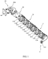
FIG. 1 is a schematic view illustrating a split-cavity and split-flow exhaust pipe assembly in an embodiment according to the present invention. -
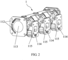
FIG. 2 is a schematic view illustrating a first exhaust pipe in the split-cavity and split-flow exhaust pipe shown inFIG. 1 . -
FIG. 3 is a schematic view of another perspective illustrating thefirst exhaust pipe 1 in the split-cavity and split-flow exhaust pipe shown inFIG. 1 . -
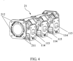
FIG. 4 is a schematic view illustrating a first exhaust pipe segment in the split-cavity and split-flow exhaust pipe shown inFIG. 1 . -
FIG. 5 is a schematic view of another perspective illustrating the first exhaust pipe segment in the split-cavity and split-flow exhaust pipe shown inFIG. 1 . -
FIG. 6 is a schematic view illustrating a second exhaust pipe segment in the split-cavity and split-flow exhaust pipe shown inFIG. 1 . -
FIG. 7 is a schematic view of another perspective illustrating the second exhaust pipe segment in the split-cavity and split-flow exhaust pipe shown inFIG. 1 . -
FIG. 8 is a schematic view illustrating a third exhaust pipe segment in the split-cavity and split-flow exhaust pipe shown inFIG. 1 . -
FIG. 9 is a schematic view of another perspective illustrating the third exhaust pipe segment in the split-cavity and split-flow exhaust pipe shown inFIG. 1 . -
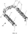
FIG. 10 is a schematic view illustrating a split-cavity and split-flow exhaust pipe assembly in a V12 engine in an embodiment according to the present invention. - The present embodiment provides an
exhaust pipe assembly 200, as illustrated inFIGS. 1 to 10 , theexhaust pipe assembly 200 is provided with anexhaust cavity 100,exhaust gas inlets 115,water inlets 114, a firstwater inlet cavity 111, and a second water inlet cavity, a water counterflow cavity, awater outlet 311 and anexhaust port 234. In the present embodiment, the .exhaust pipe assembly 200 is a split-cavity split-flow exhaust pipe assembly, where a number of theexhaust gas inlets 115 is identical as that of thewater inlets 114, and the number is not less than two, each of theexhaust gas inlets 115 is in communication with theexhaust cavity 100, a first portion of thewater inlets 114 is in communication with the firstwater inlet cavity 111, a second portion of thewater inlets 114 is in communication with the second water inlet cavity, theexhaust gas outlet 234 is arranged at a first end of theexhaust pipe assembly 200, thewater outlet 311 is arranged at a second end of theexhaust pipe assembly 200, theexhaust port 234 is adjacent to the second water inlet cavity and is in communication with theexhaust cavity 100, thewater outlet 311 is adjacent to the firstwater inlet cavity 111, and is in communication with the firstwater inlet cavity 111 and the water counterflow cavity, and the second water inlet cavity is in communication with water counterflow cavity at an end of theexhaust pipe assembly 200 adjacent to theexhaust port 234. In the present embodiment, by dividing thewater inlet 114 into two portions, and the first portion of thewater inlets 114 is in communication with the firstwater inlet cavity 111, the second portion of thewater inlets 114 is in communication with the second water inlet cavity, and liquid flowing into the firstwater inlet cavity 111 and the second water inlet cavity respectively reach thewater outlet 311 through different circulating water channels. In the present embodiment, the liquid flowing into the firstwater inlet cavity 111 and the second water inlet cavity may be cooling water or a coolant, so as to realize a split-flow design of the water channel. By making the firstwater inlet cavity 111 directly in communication with thewater outlet 311, the second water inlet cavity is firstly in communication with the water counterflow cavity at an end adjacent to theexhaust port 234, and then in communication with thewater outlet 311 through the water counterflow cavity. Theexhaust pipe assembly 200 is designed with a water inlet channel and a water return channel at the same time, which realizes a split-cavity structure of the water channel and avoids a design of an additional water return pipe, making theexhaust pipe assembly 200 more compact and attractive. - In the present embodiment, the
water outlet 311 is used to connect to a front end pipeline of an water pump of an engine, theexhaust port 234 is used to connect to an inlet end of a supercharger, and thewater inlet 114 is used to connect to a water outlet on an cylinder head of the engine, and theexhaust gas inlet 115 is used to connect to an exhaust port on the cylinder head of the engine. In the present embodiment, the firstwater inlet cavity 111 and the second water inlet cavity are located on a first side of theexhaust pipe assembly 200, and the water counterflow cavity is located on a second side of theexhaust pipe assembly 200. - Optionally, the
exhaust pipe assembly 200 in the present embodiment includes awater outlet connector 3, afirst exhaust pipe 1 and asecond exhaust pipe 2 that are sequentially in communication. Thesecond exhaust pipe 2 includes a firstexhaust pipe segment 21, a secondexhaust pipe segment 22, and a thirdexhaust pipe segment 23. Where thewater outlet 311 is provided on thewater outlet connector 3, the first portion of thewater inlets 114 and the firstwater inlet cavity 111 are both provided on thefirst exhaust pipe 1, and the second portion of thefirst water inlets 114 is provided on the firstexhaust pipe segment 21. The second water inlet cavity includes a first waterinlet cavity segment 211 provided on the firstexhaust pipe segment 21, a second waterinlet cavity segment 221 provided on the secondexhaust pipe segment 22, and a third waterinlet cavity segment 231 provided on the thirdexhaust pipe segment 23, and the first waterinlet cavity segment 211, the second waterinlet cavity segment 221, and the third waterinlet cavity segment 231 are in communication with each in sequence. - The water counterflow cavity includes a fourth
water counterflow cavity 112 provided on thefirst exhaust pipe 1, a firstwater counterflow cavity 212 provided on the firstexhaust pipe segment 21, a secondwater counterflow cavity 222 provided on the secondexhaust pipe segment 22 and a thirdwater counterflow cavity 232 provided on the thirdexhaust pipe segment 23, where the fourthwater counterflow cavity 112, the firstwater counterflow cavity 212, the secondwater counterflow cavity 222 and the thirdwater counterflow cavity 232 are in communication with each other in sequence. - The third water
inlet cavity segment 231 and the thirdwater counterflow cavity 232 are in communication with each other at an end of the thirdexhaust pipe segment 23 facing away from the firstexhaust pipe segment 21. The firstwater inlet cavity 111 and the fourthwater counterflow cavity 112 are in communication with thewater outlet 311. - The
exhaust cavity 100 includes anfirst exhaust cavity 113 provided in thefirst exhaust pipe 1, a second exhaust cavity provided in thesecond exhaust pipe 2. The second exhaust cavity includes a firstexhaust cavity segment 213 and a secondexhaust cavity segment 223 that are provided in the secondexhaust pipe segment 22, and a thirdexhaust cavity segment 233 provided in the thirdexhaust pipe segment 23. Thefirst exhaust cavity 113, the firstexhaust cavity segment 213, the secondexhaust cavity segment 223 and the thirdexhaust cavity segment 233 are in communication in sequence. The first portion of theexhaust gas inlets 115 is provided on thefirst exhaust pipe 1 and is in communication with thefirst exhaust cavity 113, the second portion of theexhaust gas inlets 115 is provided on the firstexhaust pipe segment 21 and is in communication with the firstexhaust cavity segment 213, and the firstexhaust cavity segment 213 is in communication with thefirst exhaust cavity 113. - In the present embodiment, a number of the first portion of the
exhaust gas inlets 115 is identical as that of the first portion of thewater inlets 114; and a number of the second portion of theexhaust gas inlets 115 is identical as that of the second portion of thewater inlets 114. - The
exhaust port 234 is arranged on an end of the thirdexhaust pipe segment 23 facing away from the firstexhaust pipe segment 21, and in communication with the thirdexhaust cavity segment 233. - Optionally, the second
exhaust pipe segment 22 is an elbow. - Optionally, the
water outlet connector 3, thefirst exhaust pipe 1, the firstexhaust pipe segment 21, the secondexhaust pipe segment 22, and the thirdexhaust pipe segment 23 are directly connected in sequence through end faces, and sealed at connection positions. Optionally, a first end of thefirst exhaust pipe 1 is connected to a first end of thewater outlet connector 3, a second end of thefirst exhaust pipe 1 is connected to a first end of the firstexhaust pipe segment 21, a first end of the secondexhaust pipe segment 22 is connected to a second end of the firstexhaust pipe segment 21, and a second end of the secondexhaust pipe segment 22 is connected to an end of the third exhaust pipe segment 23.The first waterinlet cavity segment 211, the second waterinlet cavity segment 221 and the third waterinlet cavity segment 231 may also be connected by way of a water bridge. Optionally, a connection hole that is in communication with the first waterinlet cavity segment 211 is openly provided in a side wall of the firstexhaust pipe segment 21 adjacent to an end of the secondexhaust pipe segment 22, connection holes that are in communication with the secondwater inlet cavity 221 are respectively openly provided on side walls of the secondexhaust pipe segment 22 adjacent to both ends of the secondexhaust pipe segment 22, and a connection hole that is in communication with the third waterinlet cavity segment 231 is openly provided on an end of the thirdexhaust pipe segment 23 adjacent to the secondexhaust pipe segment 22, where two adjacent connection holes are connected by a water pipe. Similarly, the thirdwater counterflow cavity 232, the secondwater counterflow cavity 222, the firstwater counterflow cavity 212, and the fourthwater counterflow cavity 112 may also be connected by way of the water bridge. - The
exhaust cavity 100 in the present embodiment is located in a middle position of theexhaust pipe assembly 200, the firstwater inlet cavity 111, the first waterinlet cavity segment 211, the secondwater inlet cavity 221 segment, and the third waterinlet cavity segment 231 are located on a first side of theexhaust pipe assembly 200, the thirdwater counterflow cavity 232, the secondwater counterflow cavity 222, the firstwater counterflow cavity 212, and the fourthwater counterflow cavity 112 are located on a second side of theexhaust pipe assembly 200, a water interaction port (not shown in the drawings) is provided on an end of the thirdexhaust pipe segment 23 facing away from the secondexhaust pipe segment 22, and the thirdwater counterflow cavity 232 is in communication with the third waterinlet cavity segment 231 through the water interaction port, so that the second water inlet cavity and the water counterflow cavity form a U-shaped pipeline structure. On this basis, in view that the firstwater inlet cavity 111 may efficiently take away surface heat of theexhaust pipe assembly 200, thereby improving the heat dissipation effect on the surface of theexhaust pipe assembly 200. - In the present embodiment, the first
exhaust pipe segment 21, the secondexhaust pipe segment 22, and the thirdexhaust pipe segment 23 may adopt a separated structure, which is convenient for segmented processing; or may be an integral structure, when adopted, which may save a step of segmented assembling, and has no connection portion between segments, making water and air leakage not easy to occur; the secondexhaust pipe segment 22 may also be discarded, so that the firstexhaust pipe segment 21 and the thirdexhaust pipe segment 23 are directly connected; and the secondexhaust pipe segment 22 may also be split into more segments, so that each segment has an arbitrary length, and an arbitrary shape. Certainly, theexhaust pipe 1 in the present embodiment may also be split into more segments in a style of the second exhaust pipe. An appropriate structure may be selected according to a specific shape of the engine. - Paths of exhaust and water draining in the present embodiment are as follows.
- A part of the exhaust enters the
first exhaust cavity 113 through the first portion of theexhaust gas inlets 115, and another part of the exhaust enters the firstexhaust cavity segment 213 through the second portion of theexhaust gas inlets 115, the exhaust sequentially flows along a path of thefirst exhaust cavity 113, the firstexhaust cavity segment 213, the secondexhaust cavity segment 223 and the thirdexhaust cavity segment 233, and is finally discharged through theexhaust port 234. A part of the water or coolant enters the firstwater inlet cavity 111 through the first portion of thewater inlets 114, and is directly discharged from the firstwater inlet cavity 111 through the water outlet 311.Another part of the water or coolant enters the first waterinlet cavity segment 211 through the second portion of thewater inlets 114, then sequentially pass through the first waterinlet cavity segment 211, the second waterinlet cavity segment 221, the third waterinlet cavity segment 231, the water interaction port, the thirdwater counterflow cavity 232, the secondwater counterflow cavity 222, the firstwater counterflow cavity 212 and the fourthwater counterflow cavity 112, and are discharged when finally reach thewater outlet 311. - On the other hand, the present embodiment provides an engine including the above-mentioned split-cavity and split-flow exhaust pipe assembly. The engine includes at least one group of cylinders, and a number of cylinders in each group is at least two. A number of cylinders in each group of cylinders is identical as a number of
exhaust gas inlets 115 and a number ofwater inlets 114 of the split-cavity and split-flow exhaust pipe assembly, and each cylinder of an identical group is connected to thewater inlet 114 and the water outlet in one-to-one correspondence. For example, when the engine is a V12-type engine, the engine includes two groups of cylinders, each cylinder in each group is connected to a split-cavity and split-flow exhaust pipe assembly, and a number of cylinders in each group is six, where three of the six cylinders are connected to threeexhaust gas inlets 115 and threewater inlets 114 on thefirst exhaust pipe 1, and another three of the six cylinders are connected to threeexhaust gas inlets 115 and threewater inlets 114 on the first exhaust pipe segment 21.Certainly, the above six cylinders may also be divided into two parts, where each part includes an arbitrary number of cylinders, where the arbitrary number is at least one. - Optionally, the water outlet and the exhaust port are provided on an end cover of each cylinder, the water outlet on the end cover is connected to the
water inlet 114 on theexhaust pipe assembly 200, and the exhaust port on the end cover is connected to theexhaust gas inlet 115 on theexhaust pipe assembly 200. - Optionally, when the engine is a V-type engine, end surfaces of each end of the two third
exhaust pipes segment 23 provided with theexhaust port 234 are directly connected and sealed, and the two thirdexhaust cavities segment 233 are in communication with each other. - In the present embodiment, the second water inlet cavity and the water counterflow cavity are provided on the split-cavity and split-flow exhaust pipe assembly, so that the cooling water or coolant entering the exhaust pipe from the second portion of the
water inlets 114 passes through the second water inlet cavity and the water counterflow cavity and is discharged through thewater outlet 311, so that the split-cavity and split-flow exhaust pipe assembly has both functions of water inlet and water return, achieving a purpose of splitting the cavity, making the overall design of the exhaust pipe assembly more compact, reducing redundant design for peripheral pipelines, thereby reducing space occupation, while making the overall structure more attractive. Optionally, by providing the firstwater inlet cavity 111 on the split-cavity and split-flow exhaust pipe assembly, and making the water or coolant enter the exhaust pipe from the first portion of thewater inlets 114 directly discharged through thewater outlet 311, thereby achieving the purpose of splitting flow, as well as effectively cooling the surface of the split-cavity and split-flow exhaust pipe assembly. At the same time, for the V-type engine, the water or coolant passing through the singlefirst exhaust pipe 1 or the second exhaust pipe merely accounts for 25% or less of the water pump of the engine, which may ensure a maximum possible reduction of heat loss and pressure drop of cooling water or coolant along the path on a premise of a smallest volume of the exhaust pipe assembly, so that the thermal efficiency of the engine is improved, the fuel consumption of the engine is reduced, and requirements for performance of the pump are reduced, making overall performance superior. - An exhaust pipe assembly of the present invention realizes the dual function of splitting cavity and splitting flow, making the design of the exhaust pipe assembly more compact.
| 1 . |
111. First |
| 112. Fourth |
113. |
| 114. |
115. |
| 2. |
21. First |
| 211. First water |
212. First |
| 213. First |
22. Second |
| 221. Second water |
222. Second |
| 223. Second |
23. Third |
| 231. Third water |
232. Third |
| 233. Third |
234. |
| 3. |
311. |
| 100. |
200. Exhaust pipe assembly |
Claims (12)
- An exhaust pipe assembly, comprising:an exhaust cavity (100);an exhaust port (234), communicating with the exhaust cavity (100);at least two exhaust gas inlets (115), communicating with the exhaust cavity (100), wherein theexhaust port (234) is disposed at a first end of the exhaust pipe assembly (200); characterized by further comprising:a plurality of water inlets (114), provided in the same number as the at least two exhaust gas inlets (115);a first water inlet cavity (111), communicating with a first portion of the water inlets (114);a second water inlet cavity, communicating with a second portion of the water inlets (114);a first exhaust pipe (1), a second exhaust pipe (2), and a water outlet connector (3), which are sequentially connected; a water counterflow cavity (212), which comprises a first part of the water counterflow cavity (112) provided in the first exhaust pipe (1) and a second part of the water counterflow cavity provided in the second exhaust pipe (2), wherein first part of the water counterflow cavity (112) communicates with the second part of the water counterflow cavity (212), and the second part of the water counterflow cavity (212) communicates with an end of the second water inlet cavity located at the exhaust port (234) of the exhaust pipe assembly (200); anda water outlet (311), disposed at a second end of the exhaust pipe assembly (200) and provided in the water outlet connector (3)wherein the first water inlet cavity (111) and the first part of the water counterflow cavity (112) each communicate with the water outlet (311);wherein the first portion of the water inlets (114) and the first water inlet cavity (111) are provided in the first exhaust pipe (1); the second portion of the water inlets (114) and the second water inlet cavity are provided in the second exhaust pipe (2).
- The exhaust pipe assembly of claim 1, wherein the exhaust port (234) is disposed at the end of the second exhaust pipe (2) facing away from the first exhaust pipe (1); the exhaust cavity (100) comprises a first exhaust cavity (113) provided in the first exhaust pipe (1) and a second exhaust cavity provided in the second exhaust pipe (2), wherein the first exhaust cavity (113) communicates with the second exhaust cavity, and the exhaust port (234) communicates with the second exhaust cavity;
a first portion of the exhaust gas inlets (115) is provided in the first exhaust pipe (1) and communicate with the first exhaust cavity (113), and a second portion of the exhaust gas inlets (115) is provided in the second exhaust pipe (2) and communicate with the second exhaust cavity, wherein the first portion of the exhaust gas inlets (115) are provided in the same number as the first portion of the water inlets (114), and the second portion of the exhaust gas inlets (115) are provided in the same number as the second portion of the water inlets (114). - The exhaust pipe assembly of claim 3, wherein a first end of the first exhaust pipe (1) is hermetically connected to an end of the second exhaust pipe (2), and a second end of the first exhaust pipe (1) is hermetically connected to an end of the water outlet connector (3).
- The exhaust pipe assembly of claim 3, wherein the second exhaust pipe (2) is of an integral structure.
- The exhaust pipe assembly of claim 3, wherein the second exhaust pipe (2) comprises a first exhaust pipe segment (21) and a third exhaust pipe segment (23) connected to each other, wherein the first exhaust pipe segment (21) is hermetically connected to the first exhaust pipe (1);the second portion of the water inlets (114) are provided in the first exhaust pipe segment (21); the second water inlet cavity comprises a first water inlet cavity segment (211) provided in the first exhaust pipe segment (21) and a third water inlet cavity segment (231) provided in the third exhaust pipe segment (23), wherein the second portion of the water inlets (114) each communicate with the first water inlet cavity segment (211), and the first water inlet cavity segment (211) communicate with the third water inlet cavity segment (231);the second part of the water counterflow cavity comprises a first water counterflow cavity (212) provided in the first exhaust pipe segment (21) and a third water counterflow cavity (232) provided in the third exhaust pipe segment (23), wherein the first water counterflow cavity (212) communicates with the third water counterflow cavity (232), and the first water counterflow cavity (212) communicates with the first part of the water counterflow cavity (112); andthe third water inlet cavity segment (231) communicates with the third water counterflow cavity (232) at the end of the third exhaust pipe segment (23) facing away from the first exhaust pipe segment (21).
- The exhaust pipe assembly of claim 5, wherein the second portion of the exhaust gas inlets (115) are provided in the first exhaust pipe segment (21); the second exhaust cavity comprises a first exhaust cavity segment (213) provided in the first exhaust pipe segment (21) and a third exhaust cavity segment (233) provided in the third exhaust pipe segment (23), wherein the first exhaust cavity segment (213) communicate with the third exhaust cavity segment (233), each of the second portion of the exhaust gas inlets (115) communicates with the first exhaust cavity segment (213), and first exhaust cavity segment (213) communicates with the first exhaust cavity (113); and
the exhaust port (234) is arranged at the end of the third exhaust pipe segment (23) facing away from the first exhaust pipe segment (21), and communicates with the third exhaust cavity segment (233). - The exhaust pipe assembly of claim 6, wherein the second exhaust pipe (2) further comprises a second exhaust pipe segment (22), and wherein the first exhaust pipe segment (21) communicates with the third exhaust pipe segment (23) via the second exhaust pipe segment (22);the second water inlet cavity further comprises a second water inlet cavity segment (221) provided in the second exhaust pipe segment (22), and wherein the first water inlet cavity segment (211) communicates with the third water inlet cavity segment (231) via the second water inlet cavity segment (221);the second part of the water counterflow cavity further comprises a second water counterflow cavity (222) provided in the second exhaust pipe segment (22), and wherein the first water counterflow cavity (212) communicates with the third water counterflow cavity (232) via the second water counterflow cavity (222).
- The exhaust pipe assembly of claim 7, wherein the second exhaust cavity further comprises a second exhaust cavity segment (223) provided in the second exhaust pipe segment (22), and wherein the first exhaust cavity segment (213) communicates with the third exhaust cavity segment (233) via the second exhaust cavity segment (223).
- The exhaust pipe assembly of claim 7, wherein a first end of the first exhaust pipe segment (21) is hermetically connected to an end of the first exhaust pipe (1), a second end of the first exhaust pipe segment (21) is hermetically connected to a first end of the second exhaust pipe segment (22), and a second end of the second exhaust pipe segment (22) is hermetically connected to an end of the third exhaust pipe segment (23).
- The exhaust pipe assembly of claim 7, wherein the second exhaust pipe segment (22) is an elbow.
- An engine, comprising the exhaust pipe assembly (200) of any one of claims 1 to 10.
- The engine of claim 11, further comprising a plurality of groups of cylinders, wherein each group of cylinders is connected to the exhaust pipe assembly (200), wherein the number of cylinders in each group of cylinders is identical as the number of the water inlets (114) or the exhaust gas inlets (115), and wherein the water inlets (114) and the exhaust gas inlets (115) are respectively connected to the cylinders in one-to-one correspondence.
Applications Claiming Priority (2)
| Application Number | Priority Date | Filing Date | Title |
|---|---|---|---|
| CN201711157175.3A CN107965380B (en) | 2017-11-20 | 2017-11-20 | A split-cavity split-flow exhaust pipe assembly and an engine |
| PCT/CN2017/119278 WO2019095515A1 (en) | 2017-11-20 | 2017-12-28 | Exhaust pipe assembly and engine |
Publications (4)
| Publication Number | Publication Date |
|---|---|
| EP3715598A1 EP3715598A1 (en) | 2020-09-30 |
| EP3715598A4 EP3715598A4 (en) | 2021-03-17 |
| EP3715598B1 true EP3715598B1 (en) | 2023-06-07 |
| EP3715598C0 EP3715598C0 (en) | 2023-06-07 |
Family
ID=62000309
Family Applications (1)
| Application Number | Title | Priority Date | Filing Date |
|---|---|---|---|
| EP17932064.3A Active EP3715598B1 (en) | 2017-11-20 | 2017-12-28 | Exhaust pipe assembly and engine |
Country Status (4)
| Country | Link |
|---|---|
| US (1) | US11149621B2 (en) |
| EP (1) | EP3715598B1 (en) |
| CN (1) | CN107965380B (en) |
| WO (1) | WO2019095515A1 (en) |
Families Citing this family (5)
| Publication number | Priority date | Publication date | Assignee | Title |
|---|---|---|---|---|
| CN110159402B (en) * | 2019-06-28 | 2024-01-12 | 潍柴动力股份有限公司 | An intermediate tube and post-processing assembly |
| CN110259548A (en) * | 2019-07-11 | 2019-09-20 | 河南柴油机重工有限责任公司 | A kind of Diesel Engine Exhaust Pipe modular combination water cooling shield |
| CN113738487B (en) * | 2021-09-10 | 2022-09-23 | 潍柴动力股份有限公司 | Engine advances exhaust system and has its vehicle |
| CN114625230B (en) * | 2022-03-25 | 2023-04-11 | 深圳市信雅装饰设计工程有限公司 | Architectural design figure workstation of central heat dissipation liquid cooling |
| CN115726875A (en) * | 2022-12-06 | 2023-03-03 | 哈尔滨工程大学 | A combined lightweight exhaust pipe for LNG gas engine |
Citations (1)
| Publication number | Priority date | Publication date | Assignee | Title |
|---|---|---|---|---|
| KR100391031B1 (en) * | 2001-06-13 | 2003-07-16 | 이흡시 | Exhaust manifold for turbo engine |
Family Cites Families (25)
| Publication number | Priority date | Publication date | Assignee | Title |
|---|---|---|---|---|
| DE3114404A1 (en) * | 1981-04-09 | 1982-11-11 | Motoren-Werke Mannheim AG vorm. Benz Abt. stationärer Motorenbau, 6800 Mannheim | Heat exchanger, in particular small internal-combustion engines which utilise waste heat |
| US5109668A (en) * | 1991-03-07 | 1992-05-05 | Brunswick Corporation | Marine exhaust manifold and elbow |
| US5148675A (en) * | 1991-04-26 | 1992-09-22 | Inman Frederick R | Marine exhaust manifold and header pipe system |
| US5860278A (en) * | 1996-12-23 | 1999-01-19 | Chrysler Corporation | Apparatus and method for providing a compact low pressure drop exhaust manifold |
| AU2001243313A1 (en) * | 2000-02-29 | 2001-09-12 | Bombardier Inc. | Four stroke engine with cooling system |
| US7311066B1 (en) * | 2000-05-22 | 2007-12-25 | Wbip, Llc | Controlling exhaust temperatures |
| WO2006035188A1 (en) * | 2004-09-29 | 2006-04-06 | Renault S.A.S. | Double-walled exhaust manifold |
| CN200958412Y (en) * | 2006-09-25 | 2007-10-10 | 西峡县内燃机进排气管有限责任公司 | New Water Jacket Exhaust Manifold |
| CN100582451C (en) * | 2008-06-06 | 2010-01-20 | 海宁艾斯比威机车制造有限公司 | Air discharge system of motorboat engine |
| CN102251839A (en) * | 2011-06-21 | 2011-11-23 | 潍柴动力股份有限公司 | Water jacket vent pipe |
| WO2014051437A1 (en) * | 2012-09-27 | 2014-04-03 | Marine Propulsion Technologies Limited | Marine conversion of a diesel engine |
| CN203098011U (en) * | 2012-11-29 | 2013-07-31 | 深圳市金动科力实业有限公司 | Vent pipe water cooling device and power generator unit thereof |
| CN203114393U (en) * | 2013-01-14 | 2013-08-07 | 玉柴联合动力股份有限公司 | Diesel engine water cooling air exhaust pipe |
| JP5992356B2 (en) * | 2013-03-28 | 2016-09-14 | 株式会社Ihiシバウラ | Water pump equipment |
| CN203570404U (en) * | 2013-10-08 | 2014-04-30 | 潍柴动力股份有限公司 | Impulse pressure-charging exhaust pipe of marine V-shaped engine |
| US9228462B2 (en) * | 2014-02-06 | 2016-01-05 | Caterpillar Inc. | Jacket-cooled exhaust manifold |
| JP6131920B2 (en) * | 2014-07-28 | 2017-05-24 | トヨタ自動車株式会社 | Internal combustion engine cooling structure |
| CN204060886U (en) * | 2014-09-22 | 2014-12-31 | 广西玉柴机器股份有限公司 | Internal-combustion engine vent-pipe |
| CN105986873A (en) * | 2015-02-06 | 2016-10-05 | 北京汽车动力总成有限公司 | Exhaust manifold heat shield, engine cooling waterway system and automobile |
| CN104612790A (en) * | 2015-02-12 | 2015-05-13 | 广西玉柴机器股份有限公司 | Segmental water-cooled exhaust pipe |
| US9695721B2 (en) * | 2015-05-26 | 2017-07-04 | Caterpillar Inc. | Water cooled exhaust manifold |
| CN104895659B (en) * | 2015-06-30 | 2017-10-10 | 胡晓萍 | A kind of water-cooled exhaust manifold of engine |
| CN106948932A (en) * | 2016-01-06 | 2017-07-14 | 普创新能源动力科技有限公司 | Non- natural gas used for automobile generating set |
| CN205605283U (en) * | 2016-03-11 | 2016-09-28 | 宁波诚铭模具有限公司 | Water -cooling blast pipe |
| CN206111312U (en) * | 2016-08-31 | 2017-04-19 | 克康(上海)排气控制系统有限公司 | Water -cooled exhaust manifold structure |
-
2017
- 2017-11-20 CN CN201711157175.3A patent/CN107965380B/en not_active Expired - Fee Related
- 2017-12-28 US US16/765,140 patent/US11149621B2/en active Active
- 2017-12-28 EP EP17932064.3A patent/EP3715598B1/en active Active
- 2017-12-28 WO PCT/CN2017/119278 patent/WO2019095515A1/en not_active Ceased
Patent Citations (1)
| Publication number | Priority date | Publication date | Assignee | Title |
|---|---|---|---|---|
| KR100391031B1 (en) * | 2001-06-13 | 2003-07-16 | 이흡시 | Exhaust manifold for turbo engine |
Also Published As
| Publication number | Publication date |
|---|---|
| CN107965380A (en) | 2018-04-27 |
| CN107965380B (en) | 2020-06-02 |
| EP3715598A4 (en) | 2021-03-17 |
| US11149621B2 (en) | 2021-10-19 |
| WO2019095515A1 (en) | 2019-05-23 |
| EP3715598C0 (en) | 2023-06-07 |
| US20200340387A1 (en) | 2020-10-29 |
| EP3715598A1 (en) | 2020-09-30 |
Similar Documents
| Publication | Publication Date | Title |
|---|---|---|
| JP6315020B2 (en) | Internal combustion engine | |
| KR101846459B1 (en) | Exhaust turbocharger | |
| JP4119833B2 (en) | Exhaust manifold integrated engine cooling structure | |
| US7726120B2 (en) | Controlling exhaust temperatures | |
| US8544427B2 (en) | Cooling water passage structure in cylinder head of internal combustion engine | |
| US11149621B2 (en) | Exhaust pipe assembly and engine | |
| JP2005188351A (en) | Exhaust manifold integrated engine cooling structure | |
| US20110226197A1 (en) | Cooling water passage structure in cylinder head of internal combustion engine | |
| KR20190057691A (en) | Cylinder head with intergeated exhaust manifold and engine cooling system having the same | |
| US9228479B2 (en) | Marine diesel engines | |
| US8757111B2 (en) | Engine assembly including cooling system | |
| CN114233508A (en) | Engine cylinder cover water jacket | |
| JP2009180109A (en) | Exhaust manifold integrated cylinder head cooling structure | |
| JPS61175217A (en) | Cooling structure for cylinder head | |
| CN108131212B (en) | Engine cooling jacket structure | |
| CN219733519U (en) | Cylinder head assembly, engine and vehicle | |
| JP5916366B2 (en) | Exhaust gas recirculation device | |
| WO2004111400A1 (en) | Exhaust manifold and internal combustion engine comprising an exhaust manifold | |
| JP2006329128A (en) | Internal combustion engine cooling structure | |
| CN215292700U (en) | Engine cooling structure and engine | |
| JP2007092706A (en) | engine | |
| CN117211984A (en) | An engine cylinder head water jacket | |
| CN206522194U (en) | The cooling of air intake duct and heat insulation structural | |
| JP2005016526A (en) | Outboard motor exhaust passage structure | |
| JP2022015676A (en) | Internal combustion engine |
Legal Events
| Date | Code | Title | Description |
|---|---|---|---|
| STAA | Information on the status of an ep patent application or granted ep patent |
Free format text: STATUS: THE INTERNATIONAL PUBLICATION HAS BEEN MADE |
|
| PUAI | Public reference made under article 153(3) epc to a published international application that has entered the european phase |
Free format text: ORIGINAL CODE: 0009012 |
|
| STAA | Information on the status of an ep patent application or granted ep patent |
Free format text: STATUS: REQUEST FOR EXAMINATION WAS MADE |
|
| 17P | Request for examination filed |
Effective date: 20200529 |
|
| AK | Designated contracting states |
Kind code of ref document: A1 Designated state(s): AL AT BE BG CH CY CZ DE DK EE ES FI FR GB GR HR HU IE IS IT LI LT LU LV MC MK MT NL NO PL PT RO RS SE SI SK SM TR |
|
| AX | Request for extension of the european patent |
Extension state: BA ME |
|
| DAV | Request for validation of the european patent (deleted) | ||
| DAX | Request for extension of the european patent (deleted) | ||
| A4 | Supplementary search report drawn up and despatched |
Effective date: 20210216 |
|
| RIC1 | Information provided on ipc code assigned before grant |
Ipc: F01N 3/04 20060101ALI20210210BHEP Ipc: F01N 13/08 20100101AFI20210210BHEP Ipc: F01N 13/10 20100101ALI20210210BHEP Ipc: F01N 13/00 20100101ALI20210210BHEP |
|
| GRAP | Despatch of communication of intention to grant a patent |
Free format text: ORIGINAL CODE: EPIDOSNIGR1 |
|
| STAA | Information on the status of an ep patent application or granted ep patent |
Free format text: STATUS: GRANT OF PATENT IS INTENDED |
|
| INTG | Intention to grant announced |
Effective date: 20230123 |
|
| GRAS | Grant fee paid |
Free format text: ORIGINAL CODE: EPIDOSNIGR3 |
|
| GRAA | (expected) grant |
Free format text: ORIGINAL CODE: 0009210 |
|
| STAA | Information on the status of an ep patent application or granted ep patent |
Free format text: STATUS: THE PATENT HAS BEEN GRANTED |
|
| AK | Designated contracting states |
Kind code of ref document: B1 Designated state(s): AL AT BE BG CH CY CZ DE DK EE ES FI FR GB GR HR HU IE IS IT LI LT LU LV MC MK MT NL NO PL PT RO RS SE SI SK SM TR |
|
| REG | Reference to a national code |
Ref country code: GB Ref legal event code: FG4D |
|
| REG | Reference to a national code |
Ref country code: CH Ref legal event code: EP Ref country code: AT Ref legal event code: REF Ref document number: 1575729 Country of ref document: AT Kind code of ref document: T Effective date: 20230615 |
|
| REG | Reference to a national code |
Ref country code: DE Ref legal event code: R096 Ref document number: 602017070075 Country of ref document: DE |
|
| U01 | Request for unitary effect filed |
Effective date: 20230621 |
|
| U07 | Unitary effect registered |
Designated state(s): AT BE BG DE DK EE FI FR IT LT LU LV MT NL PT SE SI Effective date: 20230707 |
|
| REG | Reference to a national code |
Ref country code: LT Ref legal event code: MG9D |
|
| PG25 | Lapsed in a contracting state [announced via postgrant information from national office to epo] |
Ref country code: NO Free format text: LAPSE BECAUSE OF FAILURE TO SUBMIT A TRANSLATION OF THE DESCRIPTION OR TO PAY THE FEE WITHIN THE PRESCRIBED TIME-LIMIT Effective date: 20230907 Ref country code: ES Free format text: LAPSE BECAUSE OF FAILURE TO SUBMIT A TRANSLATION OF THE DESCRIPTION OR TO PAY THE FEE WITHIN THE PRESCRIBED TIME-LIMIT Effective date: 20230607 |
|
| PG25 | Lapsed in a contracting state [announced via postgrant information from national office to epo] |
Ref country code: RS Free format text: LAPSE BECAUSE OF FAILURE TO SUBMIT A TRANSLATION OF THE DESCRIPTION OR TO PAY THE FEE WITHIN THE PRESCRIBED TIME-LIMIT Effective date: 20230607 Ref country code: HR Free format text: LAPSE BECAUSE OF FAILURE TO SUBMIT A TRANSLATION OF THE DESCRIPTION OR TO PAY THE FEE WITHIN THE PRESCRIBED TIME-LIMIT Effective date: 20230607 Ref country code: GR Free format text: LAPSE BECAUSE OF FAILURE TO SUBMIT A TRANSLATION OF THE DESCRIPTION OR TO PAY THE FEE WITHIN THE PRESCRIBED TIME-LIMIT Effective date: 20230908 |
|
| PG25 | Lapsed in a contracting state [announced via postgrant information from national office to epo] |
Ref country code: SK Free format text: LAPSE BECAUSE OF FAILURE TO SUBMIT A TRANSLATION OF THE DESCRIPTION OR TO PAY THE FEE WITHIN THE PRESCRIBED TIME-LIMIT Effective date: 20230607 |
|
| PG25 | Lapsed in a contracting state [announced via postgrant information from national office to epo] |
Ref country code: IS Free format text: LAPSE BECAUSE OF FAILURE TO SUBMIT A TRANSLATION OF THE DESCRIPTION OR TO PAY THE FEE WITHIN THE PRESCRIBED TIME-LIMIT Effective date: 20231007 |
|
| PG25 | Lapsed in a contracting state [announced via postgrant information from national office to epo] |
Ref country code: SM Free format text: LAPSE BECAUSE OF FAILURE TO SUBMIT A TRANSLATION OF THE DESCRIPTION OR TO PAY THE FEE WITHIN THE PRESCRIBED TIME-LIMIT Effective date: 20230607 Ref country code: SK Free format text: LAPSE BECAUSE OF FAILURE TO SUBMIT A TRANSLATION OF THE DESCRIPTION OR TO PAY THE FEE WITHIN THE PRESCRIBED TIME-LIMIT Effective date: 20230607 Ref country code: RO Free format text: LAPSE BECAUSE OF FAILURE TO SUBMIT A TRANSLATION OF THE DESCRIPTION OR TO PAY THE FEE WITHIN THE PRESCRIBED TIME-LIMIT Effective date: 20230607 Ref country code: IS Free format text: LAPSE BECAUSE OF FAILURE TO SUBMIT A TRANSLATION OF THE DESCRIPTION OR TO PAY THE FEE WITHIN THE PRESCRIBED TIME-LIMIT Effective date: 20231007 Ref country code: CZ Free format text: LAPSE BECAUSE OF FAILURE TO SUBMIT A TRANSLATION OF THE DESCRIPTION OR TO PAY THE FEE WITHIN THE PRESCRIBED TIME-LIMIT Effective date: 20230607 |
|
| U20 | Renewal fee for the european patent with unitary effect paid |
Year of fee payment: 7 Effective date: 20231227 |
|
| PG25 | Lapsed in a contracting state [announced via postgrant information from national office to epo] |
Ref country code: PL Free format text: LAPSE BECAUSE OF FAILURE TO SUBMIT A TRANSLATION OF THE DESCRIPTION OR TO PAY THE FEE WITHIN THE PRESCRIBED TIME-LIMIT Effective date: 20230607 |
|
| REG | Reference to a national code |
Ref country code: DE Ref legal event code: R097 Ref document number: 602017070075 Country of ref document: DE |
|
| PLBE | No opposition filed within time limit |
Free format text: ORIGINAL CODE: 0009261 |
|
| STAA | Information on the status of an ep patent application or granted ep patent |
Free format text: STATUS: NO OPPOSITION FILED WITHIN TIME LIMIT |
|
| 26N | No opposition filed |
Effective date: 20240308 |
|
| REG | Reference to a national code |
Ref country code: CH Ref legal event code: PL |
|
| PG25 | Lapsed in a contracting state [announced via postgrant information from national office to epo] |
Ref country code: MC Free format text: LAPSE BECAUSE OF FAILURE TO SUBMIT A TRANSLATION OF THE DESCRIPTION OR TO PAY THE FEE WITHIN THE PRESCRIBED TIME-LIMIT Effective date: 20230607 |
|
| GBPC | Gb: european patent ceased through non-payment of renewal fee |
Effective date: 20231228 |
|
| PG25 | Lapsed in a contracting state [announced via postgrant information from national office to epo] |
Ref country code: MC Free format text: LAPSE BECAUSE OF FAILURE TO SUBMIT A TRANSLATION OF THE DESCRIPTION OR TO PAY THE FEE WITHIN THE PRESCRIBED TIME-LIMIT Effective date: 20230607 |
|
| REG | Reference to a national code |
Ref country code: IE Ref legal event code: MM4A |
|
| PG25 | Lapsed in a contracting state [announced via postgrant information from national office to epo] |
Ref country code: IE Free format text: LAPSE BECAUSE OF NON-PAYMENT OF DUE FEES Effective date: 20231228 |
|
| PG25 | Lapsed in a contracting state [announced via postgrant information from national office to epo] |
Ref country code: GB Free format text: LAPSE BECAUSE OF NON-PAYMENT OF DUE FEES Effective date: 20231228 |
|
| PG25 | Lapsed in a contracting state [announced via postgrant information from national office to epo] |
Ref country code: CH Free format text: LAPSE BECAUSE OF NON-PAYMENT OF DUE FEES Effective date: 20231231 |
|
| PG25 | Lapsed in a contracting state [announced via postgrant information from national office to epo] |
Ref country code: IE Free format text: LAPSE BECAUSE OF NON-PAYMENT OF DUE FEES Effective date: 20231228 Ref country code: GB Free format text: LAPSE BECAUSE OF NON-PAYMENT OF DUE FEES Effective date: 20231228 Ref country code: CH Free format text: LAPSE BECAUSE OF NON-PAYMENT OF DUE FEES Effective date: 20231231 |
|
| PG25 | Lapsed in a contracting state [announced via postgrant information from national office to epo] |
Ref country code: CY Free format text: LAPSE BECAUSE OF FAILURE TO SUBMIT A TRANSLATION OF THE DESCRIPTION OR TO PAY THE FEE WITHIN THE PRESCRIBED TIME-LIMIT; INVALID AB INITIO Effective date: 20171228 |
|
| U90 | Renewal fees not paid: noting of loss of rights |
Free format text: RENEWAL FEE NOT PAID FOR YEAR 08 Effective date: 20250711 |
|
| PG25 | Lapsed in a contracting state [announced via postgrant information from national office to epo] |
Ref country code: HU Free format text: LAPSE BECAUSE OF FAILURE TO SUBMIT A TRANSLATION OF THE DESCRIPTION OR TO PAY THE FEE WITHIN THE PRESCRIBED TIME-LIMIT; INVALID AB INITIO Effective date: 20171228 |
|
| U93 | Unitary patent lapsed |
Free format text: RENEWAL FEE NOT PAID Effective date: 20241231 |
|
| PG25 | Lapsed in a contracting state [announced via postgrant information from national office to epo] |
Ref country code: TR Free format text: LAPSE BECAUSE OF FAILURE TO SUBMIT A TRANSLATION OF THE DESCRIPTION OR TO PAY THE FEE WITHIN THE PRESCRIBED TIME-LIMIT Effective date: 20230607 |