EP3715530B1 - Cover for a floor opening near a curb stone - Google Patents
Cover for a floor opening near a curb stone Download PDFInfo
- Publication number
- EP3715530B1 EP3715530B1 EP19166326.9A EP19166326A EP3715530B1 EP 3715530 B1 EP3715530 B1 EP 3715530B1 EP 19166326 A EP19166326 A EP 19166326A EP 3715530 B1 EP3715530 B1 EP 3715530B1
- Authority
- EP
- European Patent Office
- Prior art keywords
- frame
- cover
- cover body
- detent element
- flexurally elastic
- Prior art date
- Legal status (The legal status is an assumption and is not a legal conclusion. Google has not performed a legal analysis and makes no representation as to the accuracy of the status listed.)
- Active
Links
- 239000004575 stone Substances 0.000 title claims 2
- 238000005452 bending Methods 0.000 claims description 36
- 230000005489 elastic deformation Effects 0.000 claims description 9
- NJPPVKZQTLUDBO-UHFFFAOYSA-N novaluron Chemical compound C1=C(Cl)C(OC(F)(F)C(OC(F)(F)F)F)=CC=C1NC(=O)NC(=O)C1=C(F)C=CC=C1F NJPPVKZQTLUDBO-UHFFFAOYSA-N 0.000 description 25
- 238000010276 construction Methods 0.000 description 10
- 238000003780 insertion Methods 0.000 description 9
- 230000037431 insertion Effects 0.000 description 9
- 239000000463 material Substances 0.000 description 6
- 239000002184 metal Substances 0.000 description 5
- 229910052751 metal Inorganic materials 0.000 description 5
- 238000007789 sealing Methods 0.000 description 5
- 229910001018 Cast iron Inorganic materials 0.000 description 3
- 229910001208 Crucible steel Inorganic materials 0.000 description 3
- 238000012423 maintenance Methods 0.000 description 3
- 230000002093 peripheral effect Effects 0.000 description 3
- XEEYBQQBJWHFJM-UHFFFAOYSA-N Iron Chemical compound [Fe] XEEYBQQBJWHFJM-UHFFFAOYSA-N 0.000 description 2
- 241001310793 Podium Species 0.000 description 2
- 235000021167 banquet Nutrition 0.000 description 2
- 230000007797 corrosion Effects 0.000 description 2
- 238000005260 corrosion Methods 0.000 description 2
- 238000009434 installation Methods 0.000 description 2
- 239000010959 steel Substances 0.000 description 2
- XLYOFNOQVPJJNP-UHFFFAOYSA-N water Substances O XLYOFNOQVPJJNP-UHFFFAOYSA-N 0.000 description 2
- 229910000831 Steel Inorganic materials 0.000 description 1
- 238000004873 anchoring Methods 0.000 description 1
- 239000010426 asphalt Substances 0.000 description 1
- 230000001066 destructive effect Effects 0.000 description 1
- 230000000694 effects Effects 0.000 description 1
- 239000004519 grease Substances 0.000 description 1
- 229910052742 iron Inorganic materials 0.000 description 1
- 239000007788 liquid Substances 0.000 description 1
- 230000001681 protective effect Effects 0.000 description 1
- 239000002351 wastewater Substances 0.000 description 1
Images


Classifications
-
- E—FIXED CONSTRUCTIONS
- E01—CONSTRUCTION OF ROADS, RAILWAYS, OR BRIDGES
- E01C—CONSTRUCTION OF, OR SURFACES FOR, ROADS, SPORTS GROUNDS, OR THE LIKE; MACHINES OR AUXILIARY TOOLS FOR CONSTRUCTION OR REPAIR
- E01C11/00—Details of pavings
- E01C11/22—Gutters; Kerbs ; Surface drainage of streets, roads or like traffic areas
- E01C11/221—Kerbs or like edging members, e.g. flush kerbs, shoulder retaining means ; Joint members, connecting or load-transfer means specially for kerbs
- E01C11/223—Kerb-and-gutter structures; Kerbs with drainage openings channel or conduits, e.g. with out- or inlets, with integral gutter or with channel formed into the kerb ; Kerbs adapted to house cables or pipes, or to form conduits
-
- E—FIXED CONSTRUCTIONS
- E02—HYDRAULIC ENGINEERING; FOUNDATIONS; SOIL SHIFTING
- E02D—FOUNDATIONS; EXCAVATIONS; EMBANKMENTS; UNDERGROUND OR UNDERWATER STRUCTURES
- E02D29/00—Independent underground or underwater structures; Retaining walls
- E02D29/12—Manhole shafts; Other inspection or access chambers; Accessories therefor
- E02D29/14—Covers for manholes or the like; Frames for covers
- E02D29/1427—Locking devices
-
- E—FIXED CONSTRUCTIONS
- E03—WATER SUPPLY; SEWERAGE
- E03F—SEWERS; CESSPOOLS
- E03F5/00—Sewerage structures
- E03F5/04—Gullies inlets, road sinks, floor drains with or without odour seals or sediment traps
- E03F5/046—Gullies inlets, road sinks, floor drains with or without odour seals or sediment traps adapted to be used with kerbs
Definitions
- the invention relates to a cover for a floor opening in the area of a curb according to the preamble of claim 1.
- Covers for floor openings for example shafts for waste water or as access to underground lines and the like, are known from road construction in numerous designs. They are almost always made up of a covering body and a frame in which the covering body sits.
- the covering body and the frame are usually made of metal, in particular cast iron or steel.
- a special embodiment consists in that the cover body, which is generally horizontal, has a lateral extension, which is designed as part of a curb.
- the cover not only covers a floor opening in the area of the roadway, which is located next to a curb, but also the associated curb, especially the Banquet.
- Such covers can be advantageously used at the edges of tunnels and galleries. Due to the narrow tunnel tube, the shafts and channels are often partly below the curb and/or banquet. Such covers are also referred to as step covers for thoroughfares.
- a corresponding cover for a floor opening in the area of a curb for example, is out CH 702 821 A1 famous.
- a covering body can be inserted into a frame and then removably fastened to the frame.
- An upper side of the covering body consists essentially of a lower traffic area and a pedestal, which forms an elevated arranged pedestal area. The pedestal mimics the geometry of a curb.
- cam locks In order to secure the covering body in the inserted position in the frame, in particular against unauthorized access and undesired lifting out by suction when it is driven over, two locking devices located opposite one another are provided on the covering body below the traffic area. In practice, these are also referred to as cam locks. Such a cam lock is described in detail, for example, in DE 1 930 395 U described.
- the cam lock has a screw whose screw head sits in the traffic area and can be turned from above with a key.
- a locking element is screwed onto the screw shank, which protrudes from the underside of the cover body, and is secured against unscrewing by a securing element at the end of the screw shank.
- Friction between the screw shank and the locking element allows the latter to pivot against a stop in a pocket in the frame by turning the screw head. If you then turn the screw head further, the locking element pulls in the direction of the screw head and finally clamps the cover body to the frame. It is loosened by turning the screw head in the opposite direction. First of all, the clamping force is reduced and finally the locking element pivots out of the pocket again, so that the covering body can be lifted out of the frame. If the friction of the thread is not sufficient for pivoting out, the screw must be turned so far that the securing element collides with the locking element and a high pivoting force can thereby be exerted on the locking element.
- a cover is also known, on the underside of which two U-shaped spring elements are arranged on the flat cover body. Snap-in lugs at their ends snap into snap-in recesses when inserted into a cover frame. This creates a latching connection when inserting, which is formed on opposite short sides of the cover. As a result, the cover body is resiliently mounted in the direction of travel between the two spring-loaded snap-in connections.
- the object of the invention is to create a cover for floor openings in the area of a curb, the covering body of which can be inserted into the frame and removed again as quickly as possible without the risk of application errors, with this also being achieved to a particular extent over the entire service life and in the event of service target.
- the solution should also be cost-effective and reliable to implement. Securing the covering body in the frame should continue to protect against unintentional lifting of the covering body.
- the invention relates to a cover for a floor opening in the area of a curb, in particular a step cover, with a cover body having an upper side and an underside, the upper side having a traffic surface and an elongated platform surface of an elongated platform at the edge, the platform surface being arranged higher than the Traffic area, and with a frame in which the cover can be inserted and from which the cover can be removed.
- At least one latching connection preferably exactly two latching connections, is formed between the covering body and the frame when the covering body is (in particular completely) inserted into the frame, with the latching connection being arranged below the traffic surface and having at least one flexible latching element and one latching element receptacle.
- the cover (which can also be called a cover device) requires very little knowledge about handling.
- the latching connection can be described in that at least one latching connection, preferably exactly two latching connections, with a flexible latching element and a latching element receptacle between the cover body and the frame is formed below the traffic surface when the cover body is inserted into the frame.
- a secure anchoring of the cover body is given immediately after complete insertion of the cover.
- the cover and its snap-in connection require very little maintenance, as there are no additional components that require special attention.
- the flexurally elastic latching element does not require any displaceably or rotatably mounted components. As a result, nothing can get stuck due to dirt and corrosion. This enables quick maintenance because opening and closing is very easy. There are also no need for several special tools.
- a simple lifting or levering tool such as a pickaxe or pickaxe is sufficient to release the latching connection and open the cover body. Also after longer periods of time in which the covering body has not been opened, it can be opened quickly and without damage.
- Such covers with a pedestal are also referred to as step covers, because this pedestal is used to simulate a curb or curb element/section.
- the covering body and the frame should each have an at least essentially rectangular or square outline.
- the preferred embodiment with at least two such snap-in connections has the advantage that, on the one hand, higher forces can be absorbed and, on the other hand, the covering body can be easily clamped against the frame, which prevents noise from rattling and supports any sealing. Limiting the locking connections to two is particularly cost-effective.
- the flexurally elastic latching element is arranged on the cover body and the latching element receptacle is formed on the frame.
- This has the advantage that, in the event of damage to the flexurally elastic latching element that cannot be ruled out, a replacement cover body can be used in the short term in case of doubt.
- the flexurally elastic latching element is arranged on the frame and the latching element receptacle is formed on the cover body. As a result, damage to the flexurally elastic latching element caused by handling the cover body can be avoided.
- the flexurally elastic latching element can be designed in one piece with the component from the group covering body and frame on which it is arranged. This can be implemented particularly cost-effectively.
- the flexurally elastic latching element is fixed in a form-fitting and/or material-fitting manner to the component from the group covering body and frame on which it is arranged.
- the flexurally elastic latching element can be easily replaced if necessary.
- a receiving shoe for the flexible locking element is integrally formed on the component from the group covering body and frame on which the flexible locking element is fixed, and the flexible locking element is fixed in the receiving shoe.
- a bearing projection for the flexible latching element is integrally formed on the component from the group covering body and frame on which the flexible latching element is fixed, and the flexible latching element is arranged on the bearing projection.
- the flexurally elastic latching element is preferably integrally formed on the bearing projection or the latching element is fastened to the bearing projection. This has the advantage that the latching element can be shaped in a stable manner or a separate flexible latching element can be fixed in a stable manner on the bearing projection.
- the bearing projection preferably has a greater material thickness than the flexurally elastic latching element. Thus, the bearing projection tends to be significantly less deformed than the flexurally elastic latching element.
- the receiving shoe or the alternative bearing projection is arranged on or on the underside of the covering body.
- the flexible latching element is preferably made of metal, in particular iron or steel. A metal enables high permanent locking forces.
- the flexurally elastic latching element has a free-standing arm, at the free end of which a latching geometry is formed, which engages with the latching element receptacle when the covering body is (completely) inserted into the frame. Relatively large movements can be achieved by an arm through elastic deformation without individual deformation areas being overstressed and thus plastically deformed.
- the arm has a strip-shaped bending area, at the free end of which the latching geometry is arranged.
- a strip-shaped bending area has the advantage that bending moments of different magnitudes are present depending on the bending direction, which can be used for different states of the cover body.
- the cross-sectional dimensions of the arm should be less than its length, preferably by at least a factor of 1.5.
- the profile of the strip-shaped bending area can resemble or correspond to a flat bar.
- the strip-shaped bending area has a curvature in a relieved state, as it exists when the covering body is removed from the frame, and in a state as it exists, as it exists when the covering body is (completely) inserted into the frame on. Because of this (pre-)curvature, there is hardly any angle of attack in the area of the latching geometry at which an elastic deformation of the strip-shaped bending area cannot occur under load. Unintentional plastic deformations can be avoided in this way.
- the curvature is between 70 degrees and 110 degrees. Curvature means the change in direction when going through the curve.
- the arm is aligned at its fixed end at least substantially transversely to the elongated platform surface.
- the free end of the arm is aligned at least essentially parallel to the elongated platform surface. This applies at least in each case when the snap-in connection is arranged in the area of a front edge which is arranged opposite the elongated pedestal. In this case, the platform lies in the area of a rear edge lying opposite the front edge.
- a special design provides for the locking geometry to be an elevation on the outer radius of the free-standing arm. A relatively wide latching edge can thus be formed.
- the locking geometry can have a trapezoidal cross-sectional profile. This supports both locking and unlocking.
- the strip-shaped flexing zone has, in an unloaded state, as it exists when the covering body is removed from the frame, a curvature that is weaker than in a loaded state, as it exists when the covering body is inserted in the frame is.
- the flexurally elastic locking element is under tension in the loaded state and counteracts rattling noises, for example.
- the curvature preferably lies in a bending plane which is aligned at least essentially parallel to the traffic area.
- the cover is preferably designed in such a way that an elastic deformation of the strip-shaped bending region when the cover body is inserted into the frame is essentially characterized by a change in curvature. This achieves a defined elastic deformation.
- the cover is configured or designed in such a way that an elastic deformation of the strip-shaped bending area when the cover body is removed from the frame is characterized at least essentially by a change in curvature, in particular essentially solely by a change in curvature . This achieves a clear movement and expansions in the component can be easily calculated.
- the cover it is also possible for the cover to be configured or designed in such a way that elastic deformation of the strip-shaped bending area when the covering body is removed from the frame is characterized at least essentially by a change in curvature and by torsion of the strip-shaped bending area.
- the sequence of movements when removing the covering body from the frame can be characterized in particular by the fact that initially relatively high pull-out forces have to be applied in order to twist the strip-shaped bending area while the flexurally elastic locking element is still in engagement with the locking element receptacle.
- This consequently changes the setting angle of the strip-shaped bending area in the area of the latching element receptacle, which changes the angle between the latching edges and finally favors bending of the strip-shaped bending area.
- the torsion will release and move the latch away from the latch receptacle.
- the curvature also relaxes.
- an embodiment is advantageous in which the latching element receptacle is assigned an insertion ramp, via which the flexible latching element can be used when the Cover body is guided into the frame in the locking element recording. This makes insertion easier.
- the locking connection is designed in such a way that lower external forces are required for inserting the covering body into the frame than for removing it.
- this enables simple assembly and, on the other hand, high pull-out forces are achieved, which prevent the covering body from being lifted out unintentionally, for example due to airflow or vehicle suction.
- the design of the corresponding geometries and the bending forces of the locking connection are of the greatest importance.
- the dead weight of the covering body possibly in conjunction with a relatively small external force, can also suffice for insertion.
- the upper side of the covering body is preferably divided at least essentially into the traffic area and the platform area.
- the traffic area is preferably designed to be essentially flat and completely or essentially horizontal and extends over the entire length of the covering body.
- the platform surface is designed to be essentially flat and entirely or essentially horizontal and extends over the entire length of the covering body.
- An essentially horizontal alignment of the traffic area and the platform area is also to be understood as meaning designs that have a gradient for draining off liquid, in particular a gradient in the range of 1.5 to 10.0 degrees. Alignment also refers to the correct installation position of the cover.
- the upper side can be formed at least partially by an anti-slip profile.
- the elongated podium should have the general external shape of a curb.
- the covering body should have a curb element forming the elongated landing and a path element forming the traffic surface.
- the curb element and the path element can be designed in one piece or in one piece. This is particularly stable and easy to use.
- the curb element can also be connected to the path element in a form-fitting and/or material-fitting manner. As a result, for example, a level adjustment between the traffic area and the platform area is possible.
- a two-piece design of the cover body is also possible.
- an elongate cavity can be formed in the pedestal, in which preferably at least one supporting wall, for example a cast-in supporting wall, is arranged. Due to the cavity, the material requirement is low. A high rigidity or strength can be achieved by means of a supporting wall.
- the cover body and/or the frame are preferably made of cast metal, in particular cast iron or cast steel. These materials are each dimensionally stable, durable and inexpensive.
- an embodiment is to be preferred according to which it forms a cover receptacle into which the cover body can be inserted in such a way that at least the traffic surface is arranged flush or raised relative to the adjacent area of the frame.
- This adjoining area can be made very narrow or it itself forms a traffic area on the upper side.
- the frame has an upwardly directed leg on a rear longitudinal side, which leg interacts with the pedestal.
- the frame can have an upwardly directed limb on a front longitudinal side, which limb interacts with the traffic surface and is shorter than the limb on the rear longitudinal side.
- the frame can also have raised cheeks on its transverse sides, which face the end faces of the pedestal when the covering body is inserted in the frame, and which are higher than legs of the frame which interact with the traffic surface in the adjoining area.
- the covering body prefferably has at least one stiffening rib on the underside.
- the cover body has at least two runners on the underside, which in particular project downwards beyond the flexible latching element.
- a defined sliding movement when the covering body is pushed in can be achieved by the runners.
- the runners are preferably each rounded at at least one of their ends, in particular on the side of the front edge.
- the flexurally elastic latching element when removing and inserting the cover body from or into the frame and protected when parking the cover body on a base.
- the runners should be aligned transversely to the longitudinal direction of the platform. In other words, the runners should in particular run transversely to the front edge and rear edge of the covering body.
- a more detailed embodiment consists in that the pedestal is arranged in the area of a rear edge of the cover body and the cover has at least one access opening for receiving a tool in the area of an opposite front edge.
- the access opening can be a slot-shaped opening in the top of the covering body, which widens below the top so that an angled tool can be inserted into the access opening and is positively fixed in the access opening after a rotation of 90°, for example.
- the pedestal is arranged in the area of a rear edge of the covering body and a pivot bearing is formed between the covering body and the frame in the area of the rear edge of the covering body when the covering body is in is inserted into the frame, about which the covering body is pivoted when being inserted into and removed from the frame.
- the pedestal is again arranged in the area of the rear edge of the cover body and the cover body is in positive engagement with the frame in the area of the rear edge when it is inserted into the frame.
- the covering body is secured against lifting in the region of the rear edge.
- the covering body can have one or more, for example two or three, locking projections on the rear edge. These can be designed, for example, in the form of bolts or ribs. These locking projections should then engage in a form-fitting manner in locking recesses in the frame, in particular in their legs, when the covering body is placed in the frame.
- the bolt recesses can have a closed bottom or be designed, for example, as through-holes in the leg of the frame.
- an annular seal can be formed between the underside of the cover body and the frame when the cover body is inserted into the frame.
- the cover on the underside a circumferential Have a groove into which a sealing element is inserted.
- the cover is thus mounted with little vibration.
- the cover body preferably sits tightly in the frame when it is inserted into it.
- the cover body is preferably drawn into the frame by the latching connection in such a way that the sealing element is compressed. In this way, a surface watertight cover can be provided.
- the covering body can also have one or more water passage openings. It is then designed in the manner of a street gully.
- a traffic route construction with a primary traffic area and a peripheral kerbstone, with a cover, as described above and below, being integrated into the primary traffic area and the peripheral kerbstone in such a way that the traffic area of the covering body is at least essentially planar in the primary traffic area is located and the elongated pedestal of the cover is at least substantially integrated flush with the course of the marginal curb when the cover is inserted into the frame.
- a cavity can be opened underneath the cover, which is at least partially underneath the pedestal and/or the curb. Opening along with the area of the pedestal enables the provision of a large service access.
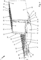
- cover 1 shows a perspective view of a cover 1 for a floor opening in the area of a curb, diagonally from above.
- This cover 1 has a cover body 10 and a frame 40 each made of cast metal, particularly cast iron or cast steel.
- the cover body 10 and the frame 40 each have an at least substantially rectangular or square outline.
- the covering body 10 has an upper side 11 and an underside 12, the upper side 11 having a traffic surface 13 and an elongated platform surface 31 of an elongated platform 30 at the edge.
- the pedestal 30 is located in particular in the area of a rear edge (cf. reference number 18 in 2 ) of the covering body 10, which faces a front edge 19.
- the elongated podium 30 has the general external shape of a curb.
- the upper side 11 of the covering body 10 is essentially divided into the traffic area 13 and the platform area 31, with the platform area 31 being arranged higher than the traffic area 13.
- the traffic area 13 is essentially flat and in the installation position it is completely or at least essentially horizontally and extends over the entire length of the cover body 10.
- the platform surface 31 is also essentially flat, in the installed position it is aligned completely or at least essentially horizontally and also extends over the entire length of the cover body 10. To bridge the height difference the traffic area 13 and the platform area 31 are connected to one another via a steep flank area 37 . The upper side 11 is partially formed by an anti-slip profiling 25 . This affects both traffic area 13 and platform area 31.
- the covering body 10 is composed of a curb element 32, which forms the elongated platform 30, and a path element 14, which forms the traffic area 13, the curb element 32 and the path element 14 being formed in one piece or in one piece, in particular being cast in one piece.
- a elongated cavity 33 is formed, which contains either air or a different filling material. The latter can serve to stiffen and/or increase the weight.
- the curb element 32 could also be connected to the path element 14 in a form-fitting and/or material-fitting manner.
- the covering body 10 can be inserted into the frame 40 and removed from it. As shown, the cover body 10 is slightly raised relative to the frame 40 at the leading edge 19 while an opposite trailing edge is still seated within the frame 40 . For this the covering body 10 has an access opening 20 in the region of the front edge 19 for receiving a tool, for example a pickaxe.
- the frame 40 forms a cover receptacle 41, into which the cover body 20 can be inserted in such a way that both the traffic surface 13 are flush with the adjacent area of the frame 40 and the platform surface 31 are flush with the adjacent area of the frame 40 (cf. on this too 4 ).
- the frame 40 has an upwardly directed leg 43 on a rear longitudinal side, which cooperates with the pedestal 30 .
- the frame 40 has an upwardly directed leg 42 on a front longitudinal side, which leg cooperates with the traffic surface 13 and is shorter than the leg 43 on the rear longitudinal side.
- the frame 40 has raised cheeks 44, 45 on its transverse sides, which face faces 35, 36 of the pedestal 30 are opposite when the covering body 10 is inserted into the frame 40. These cheeks 44, 45 are higher than the legs of the frame 40, which interact with the traffic surface 13 in the adjacent area. The height of the cheeks 44, 45 is flush with the height of the longer leg 43 on the rear longitudinal side.
- Two flexible latching elements 51 , 61 are arranged on the covering body 10 below the traffic area 13 in the area of the front edge 19 . This will be discussed in more detail in connection with the further figures.
- the gap between the covering body 10 and the frame 40 shows that the covering body 10 has five stiffening ribs 15 in the form of runners 16, 17 on the underside 12, which protrude downwards from the flexible latching element 51, 61.
- the runners 16, 17 protect the flexurally elastic latching elements 51, 61 when removing and inserting the cover body 10 from or into the frame 40 and when the cover body 10 is placed on a base.
- the runners 16, 17 are aligned transversely to the longitudinal direction of the platform 30 and therefore run transversely to the front edge 19 and rear edge 18.
- the runners 16, 17 are rounded at both of their ends. This can be seen in 1 in particular with regard to the side of the leading edge 19.
- the rounding in the region of the trailing edge 18 can be seen, for example, in FIG 2 .
- each of these latching connections 50, 60 includes a latching element receptacle 52, 62, one of the flexible latching elements 51, 61 being in engagement with one of the latching element receptacles 52, 62 when the covering body 10 is fully inserted into the frame 40 is inserted, like it too 2 indicates.
- the flexible latching elements 51, 61 at least essentially bend in a bending plane E, which is at least essentially parallel to the traffic area 13 (cf. 1 ) is aligned. The orientation of the bending plane E is shown with the normal vector next to the cover 1.
- the latching connection 50 shown has a flexible latching element 51 on the cover body 10 and a latching element receptacle 52 on the frame 40.
- the flexible latching element 51 is formed in one piece with the covering body 10 and the latching element receptacle 52 is formed by a pocket that is integrally formed on the frame 40.
- a bearing projection 53 for the flexurally elastic latching element 51 is integrally formed on the covering body 10 and the flexurally elastic latching element 51 is in turn integrally formed on the bearing projection 53 .
- the bearing projection 53 forms a kind of base and is an elevation on the underside of the covering body 10.
- the flexurally elastic locking element 51 has a free-standing arm 54, at the free end 55 of which a locking geometry 56 is formed, which engages with the locking element receptacle 52 when, as in FIG 2 shown the cover 10 is inserted into the frame 40.
- the arm 54 has a strip-shaped bending area 57, at the free end of which the latching geometry 56 is arranged.
- the cross-sectional dimensions of arm 54 are each smaller than its length.
- the profile of the strip-shaped bending area 57 is similar to that of a flat bar, but it tapers in height and material thickness in the direction of the free end.
- the strip-shaped bending area 57 has a relieved state, as it is when the cover body 10 is taken out of the frame 40 (as also in FIG 1 shown), and in a state as it is when the cover body 10 is fully inserted into the frame 40 - as in the 2 and 3 shown - each have a curvature 58 on.
- the curvature 58 is weaker in the unloaded state than in the loaded state.
- the curvature ranges between 70 degrees and 110 degrees in both states.
- the curvature in the representation is 3 about 90 degrees.
- the curvature in the unloaded state is less than 90 degrees, but in particular more than 70 degrees, for example 85 degrees.
- the angle information relates to the change in direction between the ends of the strip-shaped bending area 57.
- the arm 54 is aligned at its fixed end at least essentially transversely to the elongated platform surface 31 or to the front edge 19. At its free end, the arm 54 is aligned at least essentially parallel to the elongated platform surface 31 or to the front edge 19 .
- the latching geometry 56 is an elevation on the outer radius of the free-standing arm 54, with the latching geometry 56 having a trapezoidal cross-sectional profile.
- the curvature 58 of the strip-shaped bending region 57 lies in the bending plane E, which is at least essentially parallel to the traffic area 13 (see 1 ) is aligned.
- the locking geometry 56 is pivoted at a distance from the underside 12 of the covering body completely or at least essentially parallel to the traffic surface when the curvature 58 of the strip-shaped bending area 57 changes.
- an elastic deformation of the strip-shaped bending region 57 when the covering body 10 is removed from the frame 40 is essentially characterized by a change in the curvature 58 .
- a support wall 34 is formed, in particular as a one-piece cast element of the pedestal 30.
- the covering body 10 when the covering body 10 is inserted into the frame 40 , an annular seal 22 is formed between the underside 12 of the covering body 10 and the frame 40 .
- the covering body 10 has a circumferential groove 23 on the underside 12, into which a sealing element 24 is inserted.
- the covering body 10 sits tightly closed in the frame 40.
- the covering body 10 could also have water passage openings.
- a pivot bearing 21 is formed between the covering body 10 and the frame 40 when the covering body 10 is inserted into the frame 40, around which the covering body 10 pivots when it is inserted into and removed from the frame 40 is panned.
- the covering body 10 pivots about this pivot bearing 21 and slides in the direction of the front edge 19 or counter to it.
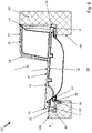
- Part of the traffic route construction 100 is a primary traffic surface 103, which can consist of an asphalt or concrete structure, for example, and a peripheral curb 102, which can consist of concrete, for example.
- the cover 1 is with her Frame 40 is installed in a floor opening 101 in such a way that it is integrated into the primary traffic area 103 and the curb 102 at the edge, in such a way that the traffic area 13 of the covering body 10 lies at least substantially planar in the primary traffic area 103 and the elongate pedestal 30 of the covering body 10 is integrated at least substantially flush into the profile of the edge-side curb 102 if the covering body 10 is as in FIG figure 5 fully inserted into the frame 40 as shown.
- a cavity 104 can be opened underneath the cover 1, for example a duct or manhole. Because of the pedestal 30 it is thus possible to provide access to a cavity 104 which is at least partially below the pedestal 30 and/or the curb 102 in an uncomplicated manner.
- FIG 5 sits the cover 10 first in the frame 40, as well as from 4 is shown.
- the flexurally elastic latching element 51 engages with the latching element receptacle 52 .
- the covering body 10 is positively engaged with the frame 40 in the region of the rear edge 18 so that it cannot be lifted at the rear edge 18 .
- the covering body 10 is already slightly lifted out of the frame 40 at the front edge 19 and pivoted relative to the frame 40 . Up to this point, the covering body 10 has hardly shifted in the direction of the front edge 19 . What is also not visible in the sectional view is that the cover body 10 is still positively engaged with the frame 40 in the area of the rear edge 18 in this pivoted position, so that it cannot be lifted at the rear edge 18 .
- the cover body 10 is pivoted further upwards relative to the frame 40 than in 6 and already partially pulled out of the frame 40 in the direction of the front edge 19 .
- the runners 16, 17 (regarding runner 17 cf. Figures 1 to 3 ) is used so that the covering body 10 can be slidably supported on the frame 40 when it is pulled out.
- the rounding of the runners 16, 17 also contributes in particular to this.
- a locking projection 26 which can be designed, for example, in the form of a bolt or ribs.
- This locking projection 26 engages in the pivoted positions 2 , 3 , 4 , 5 and 6 form-fitting in bolt recesses in the frame 40, in particular in the leg 43, a.
- the bolt recesses can have a closed bottom or can also be designed as through-holes in the leg 43 .
Description
Die Erfindung betrifft eine Abdeckung für eine Bodenöffnung im Bereich eines Bordsteins gemäß dem Oberbegriff von Anspruch 1.The invention relates to a cover for a floor opening in the area of a curb according to the preamble of
Abdeckungen für Bodenöffnungen, beispielsweise Schächte für Abwasser oder als Zugang zu unterirdisch angebrachten Leitungen und dergleichen, sind aus dem Straßenbau in zahlreichen Ausführungen bekannt. Sie setzen sich fast immer aus einem Abdeckkörper und einem Rahmen, in dem der Abdeckkörper sitzt, zusammen. Der Abdeckkörper und der Rahmen sind meist aus Metall gefertigt, insbesondere aus Gusseisen oder aus Stahl. Eine besondere Ausführungsart besteht darin, dass der im Allgemeinen waagerecht liegende Abdeckkörper eine seitliche Erweiterung aufweist, welche als Teil eines Bordsteins ausgeführt ist. Die Abdeckung deckt also nicht nur eine Bodenöffnung im Bereich der Fahrbahn ab, die sich anschließend an einen Bordstein befindet, sondern auch noch den zugehörigen Bordstein, insbesondere das Bankett. Solche Abdeckungen können vorteilhaft an den Rändern von Tunnels und Galerien eingesetzt werden. Aufgrund der beengten Tunnelröhre liegen die Schächte und Kanäle hier nämlich oftmals teilweise unterhalb des Bordsteins und/oder Banketts. Solche Abdeckungen werden auch als Stufenabdeckung für Verkehrsstraßen bezeichnet.Covers for floor openings, for example shafts for waste water or as access to underground lines and the like, are known from road construction in numerous designs. They are almost always made up of a covering body and a frame in which the covering body sits. The covering body and the frame are usually made of metal, in particular cast iron or steel. A special embodiment consists in that the cover body, which is generally horizontal, has a lateral extension, which is designed as part of a curb. The cover not only covers a floor opening in the area of the roadway, which is located next to a curb, but also the associated curb, especially the Banquet. Such covers can be advantageously used at the edges of tunnels and galleries. Due to the narrow tunnel tube, the shafts and channels are often partly below the curb and/or banquet. Such covers are also referred to as step covers for thoroughfares.
Eine entsprechende Abdeckung für eine Bodenöffnung im Bereich eines Bordsteines ist beispielsweise aus
Um den Abdeckkörper in der eingelegten Stellung im Rahmen zu sichern, insbesondere vor unbefugtem Zugang und einem ungewünschten Herausheben durch Sog bei einem Überfahren, sind unterhalb der Verkehrsfläche zwei sich gegenüberliegende Verriegelungsvorrichtungen am Abdeckkörper vorgesehen. Diese werden in der Praxis auch als Vorreiberverschluss bezeichnet. Im Detail wird ein solcher Vorreiberverschluss beispielsweise in
Bereits im Auslieferungszustand ist das Einsetzen des Abdeckkörpers in den Rahmen durch das Drehen von je einer Schraube pro Verriegelungsvorrichtung zeitintensiv und nur mit einem passenden Werkzeug durchführbar. Größere Nachteile der Verriegelungsvorrichtung bestehen vor allem über der Einsatzzeit, weil diese Verschmutzung und Korrosion ausgesetzt ist. Die Verriegelungsvorrichtung muss zumindest saubergehalten und abgeschmiert werden, damit deren Funktion dauerhaft für den Service des hinter der Abdeckung liegenden Schachtes oder Kanals gewährleistet ist. Anderenfalls setzt sich die Verriegelungsvorrichtung fest. Weil Serviceintervalle für eine Serviceabdeckung nicht wünschenswert sind und in der Praxis auch keine Berücksichtigung finden, gestaltet sich das Lösen der Verriegelungsvorrichtung oftmals als mühsam und ist nur unter Anwendung grober Gewalt möglich. Für etwaige Schäden an der Verriegelungsvorrichtung müssen stets Ersatzteile vorgehalten werden. Etwaige Tunnelsperrungen während der Wartungsarbeiten können sich durch diese Probleme erheblich verlängern. Zumindest die angrenzende Fahrbahnspur ist nämlich aus Sicherheitsgründen solange nicht befahrbar, bis der Abdeckkörper wieder gesichert in dem Rahmen sitzt.Even when delivered, the insertion of the cover into the frame by turning one screw per locking device is time-consuming and only with one suitable tool feasible. Major disadvantages of the locking device are primarily over the period of use because it is exposed to dirt and corrosion. The locking device must at least be kept clean and lubricated so that its function is permanently guaranteed for the service of the manhole or channel behind the cover. Otherwise the locking device will seize up. Because service intervals for a service coverage are not desirable and are not taken into account in practice, the release of the locking device often turns out to be tedious and is only possible with the use of brute force. Spare parts must always be kept available to cover any damage to the locking device. Any tunnel closures during maintenance work can be significantly extended due to these problems. For safety reasons, at least the adjacent lane of the road cannot be driven on until the covering body is securely seated in the frame again.
Aus der Praxis sind außerdem Fälle bekannt, in denen die Verriegelungsvorrichtung beim Einsetzen des Abdeckkörpers in den Rahmen nicht oder nur unzureichend betätigt wurde, was zu einem gefährlichen Anheben des Abdeckkörpers beim Überfahren führen kann.Cases are also known from practice in which the locking device was not or only insufficiently actuated when inserting the cover into the frame, which can lead to a dangerous lifting of the cover when driven over.
Nicht zu unterschätzen sind auch die Komplexität der Verriegelungseinrichtung mit mehreren Einzelbauteilen, die Notwendigkeit mehrere Werkzeuge nutzen zu müssen, um Schutzkappen von den Schraubenköpfen zu entfernen, die Schrauben zu bedienen und den Abdeckkörper anzuheben. Weiteres Werkzeug wird für die Wartung der Verriegelungsvorrichtung benötigt, so zum Beispiel eine Fettpresse, Schraubendreher und -schlüssel.Also not to be underestimated is the complexity of the locking device with several individual components, the need to use several tools to remove protective caps from the screw heads, to operate the screws and to lift the cover body. Other tools are required for servicing the locking device, such as a grease gun, screwdriver and wrench.
Aus
Aufgabe der Erfindung ist es, eine Abdeckung für Bodenöffnungen im Bereich eines Bordsteins zu schaffen, deren Abdeckkörper ohne die Gefahr von Anwendungsfehlern möglichst schnell in den Rahmen einlegbar und wieder entnehmbar ist, wobei dies in besonderem Maße auch über der gesamten Lebensdauer und im Servicefall erreicht werden soll. Die Lösung soll zudem kostengünstig und zuverlässig umsetzbar sein. Eine Sicherung des Abdeckkörpers in dem Rahmen soll auch weiterhin vor einem ungewollten Anheben des Abdeckkörpers schützen.The object of the invention is to create a cover for floor openings in the area of a curb, the covering body of which can be inserted into the frame and removed again as quickly as possible without the risk of application errors, with this also being achieved to a particular extent over the entire service life and in the event of service target. The solution should also be cost-effective and reliable to implement. Securing the covering body in the frame should continue to protect against unintentional lifting of the covering body.
Hauptmerkmale der Erfindung sind im kennzeichnenden Teil von Anspruch 1 angegeben. Ausgestaltungen sind Gegenstand der Ansprüche 2 bis 15 sowie der Beschreibung.Main features of the invention are set out in the characterizing part of
Die Erfindung betrifft eine Abdeckung für eine Bodenöffnung im Bereich eines Bordsteins, insbesondere eine Stufenabdeckung, mit einem Abdeckkörper mit einer Oberseite und einer Unterseite, wobei die Oberseite eine Verkehrsfläche und randseitig eine längliche Podestfläche eines länglichen Podestes aufweist, wobei die Podestfläche höher angeordnet ist als die Verkehrsfläche, und mit einem Rahmen, in den der Abdeckkörper einlegbar und aus dem der Abdeckkörper herausnehmbar ist. Zwischen dem Abdeckkörper und dem Rahmen ist wenigstens eine Rastverbindung, vorzugsweise genau zwei Rastverbindungen, ausgebildet, wenn der Abdeckkörper (insbesondere vollständig) in den Rahmen eingelegt ist, wobei die Rastverbindung unterhalb der Verkehrsfläche angeordnet ist und wenigstens ein biegeelastisches Rastelement und eine Rastelementaufnahme aufweist.The invention relates to a cover for a floor opening in the area of a curb, in particular a step cover, with a cover body having an upper side and an underside, the upper side having a traffic surface and an elongated platform surface of an elongated platform at the edge, the platform surface being arranged higher than the Traffic area, and with a frame in which the cover can be inserted and from which the cover can be removed. At least one latching connection, preferably exactly two latching connections, is formed between the covering body and the frame when the covering body is (in particular completely) inserted into the frame, with the latching connection being arranged below the traffic surface and having at least one flexible latching element and one latching element receptacle.
Ein Vorteil dieser Ausgestaltung liegt darin, dass die Abdeckung (auch als Abdeckungsvorrichtung bezeichenbar) nur sehr geringe Kenntnisse über die Handhabung benötigt. Mit anderen Worten lässt sich die Rastverbindung dadurch beschreiben, dass unterhalb der Verkehrsfläche wenigstens eine Rastverbindung, vorzugsweise genau zwei Rastverbindungen, mit einem biegeelastischen Rastelement und einer Rastelementaufnahme zwischen dem Abdeckkörper und dem Rahmen ausgebildet ist, wenn der Abdeckkörper in den Rahmen eingelegt ist.One advantage of this configuration is that the cover (which can also be called a cover device) requires very little knowledge about handling. In other words, the latching connection can be described in that at least one latching connection, preferably exactly two latching connections, with a flexible latching element and a latching element receptacle between the cover body and the frame is formed below the traffic surface when the cover body is inserted into the frame.
Die Funktionsweise der Rastverbindung führt zu einer Selbstarretierung, die kaum falsch angewendet werden kann. Eine sichere Verankerung des Abdeckkörpers ist nach vollständigem Einsetzen des Deckels sofort gegeben. Die Abdeckung und deren Rastverbindung sind sehr wartungsarm, da keine zusätzlichen Komponenten verbaut sind die eine spezielle Aufmerksamkeit benötigen. Das biegeelastische Rastelement kommt nämlich ohne verschiebbar oder drehbar gelagerte Bauteile aus. Folglich kann sich nichts durch Verschmutzung und Korrosion festsetzen. Hierdurch wird eine schnelle Wartung ermöglicht, weil das Öffnen und Schließen sehr einfach ist. Es werden auch nicht mehrere, spezielle Werkzeuge benötigt. Ein einfaches Hebe- oder Hebelwerkzeug wie eine Spitzhacke bzw. ein Pickel reicht aus, um die Rastverbindung zu lösen und den Abdeckkörper zu öffnen. Auch nach längeren Zeiträumen, in denen der Abdeckkörper nicht geöffnet wurde, ist ein schnelles und beschädigungsfreies Öffnen möglich. Derartige Abdeckungen mit einem Podest werden auch als Stufenabdeckung bezeichnet, weil dieser Podest der Nachbildung eines Bordsteines bzw. Bordsteinelementes/-abschnitts dient. Für den typischen Anwendungsfall sollten der Abdeckkörper und der Rahmen jeweils einen zumindest im Wesentlichen rechteckigen bzw. quadratischen Umriss aufweisen. Die bevorzugte Ausführungsform mit wenigstens zwei solchen Rastverbindungen hat den Vorteil, dass zum einen höhere Kräfte aufgenommen werden können, und zum anderen lässt sich der Abdeckkörper gut gegen den Rahmen spannen, was Geräusche durch Klappern verhindert und eine etwaige Dichtung unterstützt. Eine Beschränkung auf zwei der Rastverbindungen ist besonders kostengünstig.The way the snap-in connection works leads to a self-locking effect that can hardly be misused. A secure anchoring of the cover body is given immediately after complete insertion of the cover. The cover and its snap-in connection require very little maintenance, as there are no additional components that require special attention. The flexurally elastic latching element does not require any displaceably or rotatably mounted components. As a result, nothing can get stuck due to dirt and corrosion. This enables quick maintenance because opening and closing is very easy. There are also no need for several special tools. A simple lifting or levering tool such as a pickaxe or pickaxe is sufficient to release the latching connection and open the cover body. Also after longer periods of time in which the covering body has not been opened, it can be opened quickly and without damage. Such covers with a pedestal are also referred to as step covers, because this pedestal is used to simulate a curb or curb element/section. For the typical application, the covering body and the frame should each have an at least essentially rectangular or square outline. The preferred embodiment with at least two such snap-in connections has the advantage that, on the one hand, higher forces can be absorbed and, on the other hand, the covering body can be easily clamped against the frame, which prevents noise from rattling and supports any sealing. Limiting the locking connections to two is particularly cost-effective.
In einer möglichen Ausgestaltung ist vorgesehen, dass das biegeelastische Rastelement am Abdeckkörper angeordnet und die Rastelementaufnahme am Rahmen ausgebildet ist. Das hat den Vorteil, dass bei einem nicht auszuschließenden Schaden des biegeelastischen Rastelementes, im Zweifel kurzfristig ein Ersatzabdeckungskörper genutzt werden kann. In einer abweichenden möglichen Ausgestaltung ist das biegeelastische Rastelement am Rahmen angeordnet und die Rastelementaufnahme am Abdeckkörper ausgebildet. Hierdurch können Schäden an dem biegeelastischen Rastelement durch Hantieren mit dem Abdeckungskörper vermieden werden.In one possible embodiment, it is provided that the flexurally elastic latching element is arranged on the cover body and the latching element receptacle is formed on the frame. This has the advantage that, in the event of damage to the flexurally elastic latching element that cannot be ruled out, a replacement cover body can be used in the short term in case of doubt. In a different possible configuration, the flexurally elastic latching element is arranged on the frame and the latching element receptacle is formed on the cover body. As a result, damage to the flexurally elastic latching element caused by handling the cover body can be avoided.
Optional kann das biegeelastische Rastelement mit dem Bauteil aus der Gruppe Abdeckkörper und Rahmen, an dem es angeordnet ist, einteilig ausgebildet sein. Das ist besonders kostengünstig umsetzbar.Optionally, the flexurally elastic latching element can be designed in one piece with the component from the group covering body and frame on which it is arranged. This can be implemented particularly cost-effectively.
In einer anderen Variante ist das biegeelastische Rastelement formschlüssig und/oder materialschlüssig an dem Bauteil aus der Gruppe Abdeckkörper und Rahmen, an dem es angeordnet ist, festgelegt. Hierdurch ist man in der Materialwahl für den Abdeckkörper und das biegeelastische Rastelement freier. Außerdem kann das biegeelastische Rastelement bei Bedarf einfach ersetzt werden.In another variant, the flexurally elastic latching element is fixed in a form-fitting and/or material-fitting manner to the component from the group covering body and frame on which it is arranged. As a result, there is more freedom in the choice of material for the covering body and the flexible latching element. In addition, the flexurally elastic latching element can be easily replaced if necessary.
Gemäß einer speziellen Ausgestaltung ist an dem Bauteil aus der Gruppe Abdeckkörper und Rahmen, an dem das biegeelastische Rastelement festgelegt ist, ein Aufnahmeschuh für das biegeelastische Rastelement einteilig angeformt, und das biegeelastische Rastelement in dem Aufnahmeschuh festgelegt. Das hat den Vorteil, dass die Position des biegeelastischen Rastelements bei der Montage eindeutig definiert ist und außerdem eine stabile Verbindung erzielt wird. Vorzugsweise ist hierzu der Bereich des biegeelastischen Rastelementes, der in dem Aufnahmeschuh sitzt, durch den Aufnahmeschuh gegen ein Verbiegen gestützt.According to a special embodiment, a receiving shoe for the flexible locking element is integrally formed on the component from the group covering body and frame on which the flexible locking element is fixed, and the flexible locking element is fixed in the receiving shoe. This has the advantage that the position of the flexurally elastic locking element is clearly defined during assembly and also a stable connection is achieved. For this purpose, the region of the flexible latching element that sits in the receiving shoe is preferably supported against bending by the receiving shoe.
In einer anderen speziellen Ausgestaltung ist an dem Bauteil aus der Gruppe Abdeckkörper und Rahmen, an dem das biegeelastische Rastelement festgelegt ist, ein Lagervorsprung für das biegeelastische Rastelement einteilig angeformt, und das biegeelastische Rastelement ist an dem Lagervorsprung angeordnet. Vorzugsweise ist das biegeelastische Rastelement einteilig an dem Lagervorsprung angeformt oder aber das Rastelement ist an dem Lagervorsprung befestigt. Das hat den Vorteil, dass das Rastelement stabil anformbar bzw. lässt sich ein separates biegeelastisches Rastelement stabil am Lagervorsprung festlegen. Der Lagervorsprung weist vorzugsweise eine größere Materialdicke auf als das biegeelastische Rastelement. Damit tendiert der Lagervorsprung deutlich weniger zu Verformung als das biegeelastische Rastelement.In another special embodiment, a bearing projection for the flexible latching element is integrally formed on the component from the group covering body and frame on which the flexible latching element is fixed, and the flexible latching element is arranged on the bearing projection. The flexurally elastic latching element is preferably integrally formed on the bearing projection or the latching element is fastened to the bearing projection. This has the advantage that the latching element can be shaped in a stable manner or a separate flexible latching element can be fixed in a stable manner on the bearing projection. The bearing projection preferably has a greater material thickness than the flexurally elastic latching element. Thus, the bearing projection tends to be significantly less deformed than the flexurally elastic latching element.
In einer bevorzugten Ausführungsform ist der Aufnahmeschuh bzw. der alternative Lagervorsprung auf oder an der Unterseite des Abdeckkörpers angeordnet.In a preferred embodiment, the receiving shoe or the alternative bearing projection is arranged on or on the underside of the covering body.
Bevorzugt besteht das biegeelastische Rastelement aus Metall, insbesondere Eisen oder Stahl. Ein Metall ermöglicht hohe dauerhafte Rastkräfte.The flexible latching element is preferably made of metal, in particular iron or steel. A metal enables high permanent locking forces.
Bei einer speziellen Konstruktion weist das biegeelastische Rastelement einen freistehenden Arm auf, an dessen freien Ende eine Rastgeometrie ausgebildet ist, die mit der Rastelementaufnahme in Eingriff steht, wenn der Abdeckkörper (vollständig) in den Rahmen eingelegt ist. Durch einen Arm lassen sich relativ große Bewegungen durch elastische Verformung erzielen, ohne dass einzelne Verformungsbereiche überbeansprucht und hierdurch plastisch verformt werden.In a special construction, the flexurally elastic latching element has a free-standing arm, at the free end of which a latching geometry is formed, which engages with the latching element receptacle when the covering body is (completely) inserted into the frame. Relatively large movements can be achieved by an arm through elastic deformation without individual deformation areas being overstressed and thus plastically deformed.
Optional weist der Arm einen streifenförmigen Biegebereich auf, an dessen freien Ende die Rastgeometrie angeordnet ist. Ein streifenförmiger Biegebereich hat den Vorteil, dass unterschiedlich große Biegemomente in Abhängigkeit der Biegerichtung vorliegen, welche sich für unterschiedliche Zustände des Abdeckungskörpers ausnutzen lassen. Die Querschnittsabmessungen des Armes sollten kleiner sein als dessen Länge, vorzugsweise wenigstens um den Faktor 1,5. Damit wird eine relativ große Auslage erzielt, wodurch große Positionsänderungen der Rastgeometrie nur geringe lokale Verformungen über dem streifenförmigen Biegebereich erfordern. Beispielsweise kann der streifenförmige Biegebereich im Profil einem Flacheisen ähneln oder entsprechen.Optionally, the arm has a strip-shaped bending area, at the free end of which the latching geometry is arranged. A strip-shaped bending area has the advantage that bending moments of different magnitudes are present depending on the bending direction, which can be used for different states of the cover body. The cross-sectional dimensions of the arm should be less than its length, preferably by at least a factor of 1.5. Thus, a relatively large display is achieved, whereby large changes in position of the locking geometry only small local deformations over the require strip-shaped bending area. For example, the profile of the strip-shaped bending area can resemble or correspond to a flat bar.
In einer besonderen Ausführungsform weist der streifenförmige Biegebereich in einem entlasteten Zustand, wie er vorliegt, wenn der Abdeckkörper aus dem Rahmen herausgenommen ist, und in einem Zustand, wie er vorliegt, wenn der Abdeckkörper in den Rahmen (vollständig) eingelegt ist, jeweils eine Krümmung auf. Aufgrund dieser (Vor-)Krümmung gibt es kaum einen Angriffswinkel im Bereich der Rastgeometrie, bei dem es bei Belastung nicht zu einer elastischen Verformung des streifenförmigen Biegebereiches kommen kann. Unbeabsichtigte plastische Verformungen lassen sich hierdurch vermeiden. Vorzugsweise beträgt die Krümmung zwischen 70 Grad und 110 Grad. Unter der Krümmung ist die Richtungsänderung beim Durchlaufen der Kurve zu verstehen. Weiterhin ist bevorzugt, dass der Arm an seinem festgelegten Ende zumindest im Wesentlichen quer zur länglichen Podestfläche ausgerichtet ist. Des Weiteren ist bevorzugt, wenn der Arm an seinem freien Ende zumindest im Wesentlichen parallel zur länglichen Podestfläche ausgerichtet ist. Dies gilt zumindest jeweils dann, wenn die Rastverbindung im Bereich einer Vorderkante angeordnet ist, die dem länglichen Podest gegenüberliegend angeordnet ist. Der Podest liegt in diesem Fall im Bereich einer der Vorderkante gegenüber liegenden Hinterkante.In a particular embodiment, the strip-shaped bending area has a curvature in a relieved state, as it exists when the covering body is removed from the frame, and in a state as it exists, as it exists when the covering body is (completely) inserted into the frame on. Because of this (pre-)curvature, there is hardly any angle of attack in the area of the latching geometry at which an elastic deformation of the strip-shaped bending area cannot occur under load. Unintentional plastic deformations can be avoided in this way. Preferably the curvature is between 70 degrees and 110 degrees. Curvature means the change in direction when going through the curve. Furthermore, it is preferred that the arm is aligned at its fixed end at least substantially transversely to the elongated platform surface. Furthermore, it is preferred if the free end of the arm is aligned at least essentially parallel to the elongated platform surface. This applies at least in each case when the snap-in connection is arranged in the area of a front edge which is arranged opposite the elongated pedestal. In this case, the platform lies in the area of a rear edge lying opposite the front edge.
Bei einem speziellen Design ist vorgesehen, dass die Rastgeometrie eine Erhebung auf dem Außenradius des freistehenden Arms ist. Damit kann eine verhältnismäßige breite Rastkante ausgebildet werden.A special design provides for the locking geometry to be an elevation on the outer radius of the free-standing arm. A relatively wide latching edge can thus be formed.
Optional kann die Rastgeometrie ein trapezförmiges Querschnittsprofil aufweisen. Hierdurch wird sowohl ein Einrasten als auch ein Ausrasten unterstützt.Optionally, the locking geometry can have a trapezoidal cross-sectional profile. This supports both locking and unlocking.
Gemäß einer speziellen Variante weist der streifenförmige Biegebereich in einem entlasteten Zustand, wie er vorliegt, wenn der Abdeckkörper aus dem Rahmen herausgenommen ist, eine Krümmung auf, die schwächer ist als in einem belastetet Zustand, wie er vorliegt, wenn der Abdeckkörper in den Rahmen eingelegt ist. Hierdurch steht das biegeelastische Rastelement im belasteten Zustand unter Spannung und wirkt beispielsweise Klappergeräuschen entgegen.According to a particular variant, the strip-shaped flexing zone has, in an unloaded state, as it exists when the covering body is removed from the frame, a curvature that is weaker than in a loaded state, as it exists when the covering body is inserted in the frame is. As a result, the flexurally elastic locking element is under tension in the loaded state and counteracts rattling noises, for example.
Bevorzugt liegt die Krümmung in einer Biegeebene, die zumindest im Wesentlichen parallel zur Verkehrsfläche ausgerichtet ist. Hierdurch kann die Rastgeometrie in dieser parallelen Ebene in die Rastelementaufnahme springen und sich in dieser Richtung abstützen.The curvature preferably lies in a bending plane which is aligned at least essentially parallel to the traffic area. As a result, the latching geometry can jump into the latching element receptacle in this parallel plane and be supported in this direction.
Vorzugsweise ist die Abdeckung derart ausgestaltet, dass eine elastische Verformung des streifenförmigen Biegebereichs bei einem Einlegen des Abdeckkörpers in den Rahmen im Wesentlichen durch eine Änderung der Krümmung gekennzeichnet ist. Damit wird eine definierte elastische Verformung erzielt.The cover is preferably designed in such a way that an elastic deformation of the strip-shaped bending region when the cover body is inserted into the frame is essentially characterized by a change in curvature. This achieves a defined elastic deformation.
Gemäß einer speziellen Ausführung ist die Abdeckung so ausgestaltet bzw. derart ausgelegt, dass eine elastische Verformung des streifenförmigen Biegebereichs bei einem Herausnehmen des Abdeckkörpers aus dem Rahmen zumindest im Wesentlichen durch eine Änderung der Krümmung gekennzeichnet ist, dies insbesondere im Wesentlichen allein durch eine Änderung der Krümmung. Hierdurch wird eine eindeutige Bewegung erzielt und Dehnungen im Bauteil lassen sich gut kalkulieren.According to a special embodiment, the cover is configured or designed in such a way that an elastic deformation of the strip-shaped bending area when the cover body is removed from the frame is characterized at least essentially by a change in curvature, in particular essentially solely by a change in curvature . This achieves a clear movement and expansions in the component can be easily calculated.
Alternativ ist es auch möglich, dass die Abdeckung so ausgestaltet bzw. derart ausgelegt ist, dass eine elastische Verformung des streifenförmigen Biegebereichs bei einem Herausnehmen des Abdeckkörpers aus dem Rahmen zumindest im Wesentlichen durch eine Änderung der Krümmung und durch eine Torsion des streifenförmigen Biegebereichs gekennzeichnet ist. So ist es insbesondere möglich, auf der einen Seite das Einlegen des Abdeckkörpers in den Rahmen mit relativ leichten notwendige Kräfte zu realisieren, und auf der anderen Seite relativ hohe Auszugskräfte zum Sichern des Abdeckkörpers in dem Rahmen zu erzielen. Trotzdem ist ein zerstörungsfreies Lösen der Rastverbindung möglich. Der Bewegungsablauf beim Herausnehmen des Abdeckkörpers aus dem Rahmen kann sich insbesondere dadurch auszeichnen, dass zunächst relativ hohe Auszugskräfte aufgebracht werden müssen, um den streifenförmigen Biegebereich zu tordieren, während das biegeelastische Rastelement noch mit der Rastelementaufnahme in Eingriff steht. Hierdurch ändert sich folglich der Anstellwinkel des streifenförmigen Biegebereichs im Bereich der Rastelementaufnahme, was die Winkel zwischen den Rastkanten ändert und schließlich ein Biegen des streifenförmigen Biegebereichs begünstigt. Sobald die Biegung dann zunimmt und das Rastelement aus der Rastelementaufnahme herausspringt, wird sich die Torsion lösen und das Rastelement von der Rastelementaufnahme wegbewegen. Spätestens wenn das biegeelastische Rastelement dann keinen Kontakt mehr hat, entspannt sich auch die Krümmung.Alternatively, it is also possible for the cover to be configured or designed in such a way that elastic deformation of the strip-shaped bending area when the covering body is removed from the frame is characterized at least essentially by a change in curvature and by torsion of the strip-shaped bending area. In particular, it is possible, on the one hand, to insert the covering body into the frame with the relatively light forces required and, on the other hand, to achieve relatively high pull-out forces for securing the covering body in the frame. Nevertheless, a non-destructive release of the locking connection is possible. The sequence of movements when removing the covering body from the frame can be characterized in particular by the fact that initially relatively high pull-out forces have to be applied in order to twist the strip-shaped bending area while the flexurally elastic locking element is still in engagement with the locking element receptacle. This consequently changes the setting angle of the strip-shaped bending area in the area of the latching element receptacle, which changes the angle between the latching edges and finally favors bending of the strip-shaped bending area. Then, as the deflection increases and the latch pops out of the latch receptacle, the torsion will release and move the latch away from the latch receptacle. At the latest when the flexurally elastic latching element no longer has any contact, the curvature also relaxes.
Weiterhin ist eine Ausgestaltung von Vorteil, bei der der Rastelementaufnahme eine Einführrampe zugeordnet ist, über die das biegeelastische Rastelement bei einem Einlegen des Abdeckkörpers in den Rahmen in die Rastelementaufnahme geführt wird. Das erleichtert das Einsetzen.Furthermore, an embodiment is advantageous in which the latching element receptacle is assigned an insertion ramp, via which the flexible latching element can be used when the Cover body is guided into the frame in the locking element recording. This makes insertion easier.
In einer bevorzugten Ausführungsform ist die Rastverbindung so ausgeführt, dass für das Einlegen des Abdeckkörpers in den Rahmen geringere externe Kräfte notwendig sind als für das Herausnehmen. Damit gelingt einerseits eine einfache Montage und andererseits werden hohe Auszugskräfte erzielt, die ein ungewolltes Herausheben des Abdeckkörpers verhindern, bspw. durch Fahrtwind oder Fahrzeugsog. Die größte Bedeutung hat dabei die Auslegung der korrespondierenden Geometrien und der Biegekräfte der Rastverbindung. Für das Einlegen kann bei entsprechender Auslegung der Rastverbindung auch das Eigengewicht des Abdeckkörpers ggf. in Verbindung mit einer relativ kleinen externen Kraft genügen.In a preferred embodiment, the locking connection is designed in such a way that lower external forces are required for inserting the covering body into the frame than for removing it. On the one hand, this enables simple assembly and, on the other hand, high pull-out forces are achieved, which prevent the covering body from being lifted out unintentionally, for example due to airflow or vehicle suction. The design of the corresponding geometries and the bending forces of the locking connection are of the greatest importance. With a corresponding design of the latching connection, the dead weight of the covering body, possibly in conjunction with a relatively small external force, can also suffice for insertion.
Die Oberseite des Abdeckkörpers ist vorzugsweise zumindest im Wesentlichen in die Verkehrsfläche und die Podestfläche unterteilt. Hinzu kann optional eine mehr oder weniger steile Flankenfläche zwischen der Verkehrsfläche und der Podestfläche kommen.The upper side of the covering body is preferably divided at least essentially into the traffic area and the platform area. In addition, there can optionally be a more or less steep side surface between the traffic area and the platform area.
Die Verkehrsfläche ist bevorzugt im Wesentlichen eben und ganz oder im Wesentlichen waagerecht ausgebildet und erstreckt sich über die gesamte Länge des Abdeckkörpers. Außerdem ist es bevorzugt, wenn die Podestfläche im Wesentlichen eben und ganz oder im Wesentlichen waagerecht ausgebildet ist und sich über die gesamte Länge des Abdeckkörpers erstreckt. Als im Wesentliche waagerechte Ausrichtung der Verkehrsfläche und der Podestfläche sind auch Ausführungen zu verstehen, die ein Gefälle für das Ableiten von Flüssigkeit aufweisen, insbesondere ein Gefälle im Bereich von 1,5 bis 10,0 Grad. Die Ausrichtung bezieht sich außerdem auf die ordnungsgemäße Einbaulage der Abdeckung. Dabei kann die Oberseite zumindest teilweise durch eine rutschhemmende Profilierung ausgebildet sein.The traffic area is preferably designed to be essentially flat and completely or essentially horizontal and extends over the entire length of the covering body. In addition, it is preferred if the platform surface is designed to be essentially flat and entirely or essentially horizontal and extends over the entire length of the covering body. An essentially horizontal alignment of the traffic area and the platform area is also to be understood as meaning designs that have a gradient for draining off liquid, in particular a gradient in the range of 1.5 to 10.0 degrees. Alignment also refers to the correct installation position of the cover. The upper side can be formed at least partially by an anti-slip profile.
Der längliche Podest sollte die allgemeine äußere Form eines Bordsteins besitzen. Im Besonderen sollte der Abdeckkörper ein Bordsteinelement, das den länglichen Podest ausbildet, und ein Wegelement, das die Verkehrsfläche ausbildet, aufweisen. Dabei können das Bordsteinelement und das Wegelement einteilig bzw. einstückig ausgebildet sein. Das ist besonders stabil und einfach in der Handhabung. Alternativ kann das Bordsteinelement aber auch form- und/oder materialschlüssig mit dem Wegelement verbunden sein. Hierdurch ist beispielsweise eine Niveauanpassung zwischen der Verkehrs- und der Podestfläche möglich. Optional ist auch eine zweiteilige Ausführung des Abdeckkörpers möglich.The elongated podium should have the general external shape of a curb. In particular, the covering body should have a curb element forming the elongated landing and a path element forming the traffic surface. The curb element and the path element can be designed in one piece or in one piece. This is particularly stable and easy to use. Alternatively, the curb element can also be connected to the path element in a form-fitting and/or material-fitting manner. As a result, for example, a level adjustment between the traffic area and the platform area is possible. Optionally, a two-piece design of the cover body is also possible.
Des Weiteren kann in dem Podest ein länglicher Hohlraum ausgebildet sein, in dem vorzugsweise wenigstens eine Stützwand, beispielsweise eine eingegossene Stützwand, angeordnet ist. Durch den Hohlraum ist der Materialbedarf gering. Mittels einer Stützwand lässt sich eine hohe Steifigkeit bzw. Festigkeit erzielen.Furthermore, an elongate cavity can be formed in the pedestal, in which preferably at least one supporting wall, for example a cast-in supporting wall, is arranged. Due to the cavity, the material requirement is low. A high rigidity or strength can be achieved by means of a supporting wall.
Bevorzugt bestehen der Abdeckkörper und/oder der Rahmen aus Gussmetall, insbesondere Gusseisen oder Gussstahl. Diese Werkstoffe sind jeweils formfest, widerstandsfähig und preisgünstig.The cover body and/or the frame are preferably made of cast metal, in particular cast iron or cast steel. These materials are each dimensionally stable, durable and inexpensive.
Hinsichtlich des Rahmens ist eine Ausgestaltung zu bevorzugen, gemäß der dieser eine Abdeckungsaufnahme ausbildet, in die der Abdeckungskörper derart einsetzbar ist, dass zumindest die Verkehrsfläche flächenbündig oder erhaben relativ zum angrenzenden Bereich des Rahmens angeordnet ist. Dieser angrenzende Bereich kann sehr schmal ausgebildet sein oder aber er bildet selbst eine Verkehrsfläche auf der Oberseite aus. Für eine einfache Montage bietet sich eine Gestalt an, bei der der Rahmen an einer hinteren Längsseite einen nach oben ausgerichteten Schenkel aufweist, der mit dem Podest zusammenwirkt. Gegenüberliegend kann der Rahmen an einer vorderen Längsseite einen nach oben ausgerichteten Schenkel aufweisen, der mit der Verkehrsfläche zusammenwirkt und kürzer ist als der Schenkel an der hinteren Längsseite. Hierdurch entsteht zumindest visuell der Eindruck eines U-förmigen Querschnitts, wobei die U-Form zwei verschieden lange Schenkel besitzt und der längere der Schenkel mit dem Podest zusammenwirkt. Der Rahmen kann außerdem erhöhte Wangen an seinen Querseiten aufweisen, welche den Stirnflächen des Podestes gegenüberstehen, wenn der Abdeckkörper in den Rahmen eingelegt ist, und die höher sind als Schenkel des Rahmens, die im angrenzenden Bereich mit der Verkehrsfläche zusammenwirken.With regard to the frame, an embodiment is to be preferred according to which it forms a cover receptacle into which the cover body can be inserted in such a way that at least the traffic surface is arranged flush or raised relative to the adjacent area of the frame. This adjoining area can be made very narrow or it itself forms a traffic area on the upper side. For simple assembly, a design is available in which the frame has an upwardly directed leg on a rear longitudinal side, which leg interacts with the pedestal. On the opposite side, the frame can have an upwardly directed limb on a front longitudinal side, which limb interacts with the traffic surface and is shorter than the limb on the rear longitudinal side. This creates the impression, at least visually, of a U-shaped cross section, the U-shape having two legs of different lengths and the longer of the legs interacting with the platform. The frame can also have raised cheeks on its transverse sides, which face the end faces of the pedestal when the covering body is inserted in the frame, and which are higher than legs of the frame which interact with the traffic surface in the adjoining area.
Zur Erhöhung der Steifigkeit ist es optional möglich, dass der Abdeckkörper auf der Unterseite wenigstens eine Versteifungsrippe aufweist.To increase the rigidity, it is optionally possible for the covering body to have at least one stiffening rib on the underside.
Fernerhin ist eine Ausführung von Vorteil, gemäß der der Abdeckkörper auf der Unterseite wenigstens zwei Kufen aufweist, welche insbesondere das biegeelastische Rastelement nach unten überragen. Durch die Kufen kann eine definierte Gleitbewegung beim Einschieben des Abdeckkörpers erzielt werden. Hierzu sind die Kufen vorzugsweise jeweils an wenigstens einem ihrer Enden abgerundet, insbesondere auf der Seite der Vorderkante. Außerdem ist das biegeelastische Rastelement beim Abnehmen und Einsetzen des Abdeckkörpers vom bzw. in den Rahmen und beim Abstellen des Abdeckkörpers auf einer Unterlage geschützt. Die Kufen sollten quer zur Längsrichtung des Podestes ausgerichtet sein. Mit anderen Worten sollten die Kufen insbesondere quer zur Vorderkante und Hinterkante des Abdeckkörpers verlaufen.Furthermore, an embodiment is advantageous according to which the cover body has at least two runners on the underside, which in particular project downwards beyond the flexible latching element. A defined sliding movement when the covering body is pushed in can be achieved by the runners. For this purpose, the runners are preferably each rounded at at least one of their ends, in particular on the side of the front edge. In addition, the flexurally elastic latching element when removing and inserting the cover body from or into the frame and protected when parking the cover body on a base. The runners should be aligned transversely to the longitudinal direction of the platform. In other words, the runners should in particular run transversely to the front edge and rear edge of the covering body.
Eine nähere Ausgestaltung besteht darin, dass der Podest im Bereich einer Hinterkante des Abdeckkörpers angeordnet ist und die Abdeckung im Bereich einer gegenüberliegenden Vorderkante wenigstens eine Eingriffsöffnung für die Aufnahme eines Werkzeugs aufweist. Dies unterstützt ein ergonomisches Anheben des Abdeckkörpers inklusive Überwindung der Kräfte der Rastverbindung. Beispielsweise kann die Eingriffsöffnung eine schlitzförmige Öffnung in der Oberseite des Abdeckkörpers sein, die sich unterhalb der Oberseite erweitert, sodass ein abgewinkeltes Werkzeug in die Eingriffsöffnung einführbar ist und nach einer Drehung um beispielsweise 90° formschlüssig in der Eingriffsöffnung festgelegt ist.A more detailed embodiment consists in that the pedestal is arranged in the area of a rear edge of the cover body and the cover has at least one access opening for receiving a tool in the area of an opposite front edge. This supports an ergonomic lifting of the cover including overcoming the forces of the snap-in connection. For example, the access opening can be a slot-shaped opening in the top of the covering body, which widens below the top so that an angled tool can be inserted into the access opening and is positively fixed in the access opening after a rotation of 90°, for example.
Zur Erzielung einer harmonischen und definierten Bewegung des Abdeckkörpers relativ zum Rahmen, kann vorgesehen sein, dass der Podest im Bereich einer Hinterkante des Abdeckkörpers angeordnet ist und im Bereich der Hinterkante des Abdeckkörpers ein Schwenklager zwischen dem Abdeckkörper und dem Rahmen ausgebildet ist, wenn der Abdeckkörper in den Rahmen eingelegt ist, um das der Abdeckkörper bei einem Einlegen in den und einem Herausnehmen aus dem Rahmen geschwenkt wird.In order to achieve a harmonious and defined movement of the covering body relative to the frame, it can be provided that the pedestal is arranged in the area of a rear edge of the covering body and a pivot bearing is formed between the covering body and the frame in the area of the rear edge of the covering body when the covering body is in is inserted into the frame, about which the covering body is pivoted when being inserted into and removed from the frame.
Gemäß einer speziellen Ausführung der Abdeckung ist der Podest wiederum im Bereich der Hinterkante des Abdeckkörpers angeordnet und der Abdeckkörper steht im Bereich der Hinterkante formschlüssig mit dem Rahmen in Eingriff, wenn er in den Rahmen eingelegt ist. Hierdurch ist der Abdeckkörper im Bereich der Hinterkante gegen ein Anheben gesichert. Beispielsweise kann der Abdeckkörper an der Hinterkante einen oder mehrere, beispielsweise zwei oder drei, Riegelvorsprünge aufweisen. Diese können beispielsweise bolzenförmig oder rippenförmig ausgestaltet sein. Diese Riegelvorsprünge sollten dann formschlüssig in Riegelausnehmungen in dem Rahmen, insbesondere in deren Schenkel, eingreifen, wenn der Abdeckkörper in den Rahmen eingelegt ist. Optional können die Riegelausnehmungen einen geschlossenen Boden haben oder beispielsweise als Durchgangslöcher in dem Schenkel des Rahmens ausgebildet sein.According to a special embodiment of the cover, the pedestal is again arranged in the area of the rear edge of the cover body and the cover body is in positive engagement with the frame in the area of the rear edge when it is inserted into the frame. As a result, the covering body is secured against lifting in the region of the rear edge. For example, the covering body can have one or more, for example two or three, locking projections on the rear edge. These can be designed, for example, in the form of bolts or ribs. These locking projections should then engage in a form-fitting manner in locking recesses in the frame, in particular in their legs, when the covering body is placed in the frame. Optionally, the bolt recesses can have a closed bottom or be designed, for example, as through-holes in the leg of the frame.
Für eine abgedichtete Ausführungsform der Abdeckung kann zwischen der Unterseite des Abdeckkörpers und dem Rahmen eine Ringdichtung ausgebildet sein, wenn der Abdeckkörper in den Rahmen eingelegt ist. Hierzu kann der Abdeckkörper auf der Unterseite eine umlaufende Nut aufweisen, in welche ein Dichtelement eingesetzt ist. Damit ist die Abdeckung vibrationsarm gelagert. Bevorzugt sitzt der Abdeckkörper dicht schließend im Rahmen, wenn er in diesen eingelegt ist. Dabei wird der Abdeckkörper vorzugsweise durch die Rastverbindung so in den Rahmen gezogen, dass das Dichtelement komprimiert ist. Es lässt sich hierdurch eine tagwasserdichte Abdeckung bereitstellen. Alternativ kann der Abdeckkörper auch eine oder mehrere Wasserdurchtrittsöffnungen aufweisen. Er ist dann in der Art eines Straßenablaufes ausgeführt.For a sealed embodiment of the cover, an annular seal can be formed between the underside of the cover body and the frame when the cover body is inserted into the frame. For this purpose, the cover on the underside a circumferential Have a groove into which a sealing element is inserted. The cover is thus mounted with little vibration. The cover body preferably sits tightly in the frame when it is inserted into it. The cover body is preferably drawn into the frame by the latching connection in such a way that the sealing element is compressed. In this way, a surface watertight cover can be provided. Alternatively, the covering body can also have one or more water passage openings. It is then designed in the manner of a street gully.
Es gibt außerdem eine Verkehrswegekonstruktion mit einer primären Verkehrsfläche und einem randseitigen Bordstein, wobei eine Abdeckung, wie sie vor- und nachstehend beschrieben ist, derart in die primäre Verkehrsfläche und den randseitigen Bordstein integriert ist, dass die Verkehrsfläche des Abdeckkörpers zumindest im Wesentlichen plan in der primären Verkehrsfläche liegt und der längliche Podest des Abdeckkörpers zumindest im Wesentlichen bündig in den Verlauf des randseitigen Bordsteins integriert ist, wenn der Abdeckkörper in den Rahmen eingelegt ist. Auf diese Weise lässt sich beispielsweise ein Hohlraum unterhalb der Abdeckung öffnen, der zumindest teilweise unterhalb des Podestes und/oder des Bordsteins liegt. Ein Öffnen samt dem Bereich des Podestes ermöglicht die Bereitstellung eines großen Servicezugangs.There is also a traffic route construction with a primary traffic area and a peripheral kerbstone, with a cover, as described above and below, being integrated into the primary traffic area and the peripheral kerbstone in such a way that the traffic area of the covering body is at least essentially planar in the primary traffic area is located and the elongated pedestal of the cover is at least substantially integrated flush with the course of the marginal curb when the cover is inserted into the frame. In this way, for example, a cavity can be opened underneath the cover, which is at least partially underneath the pedestal and/or the curb. Opening along with the area of the pedestal enables the provision of a large service access.
Weitere Merkmale, Einzelheiten und Vorteile der Erfindung ergeben sich aus dem Wortlaut der Ansprüche sowie aus der folgenden Beschreibung von Ausführungsbeispielen anhand der Zeichnungen. Es zeigen:
- Fig. 1
- eine perspektivische Ansicht einer Abdeckung von schräg-oben;
- Fig. 2
- eine perspektivische Ansicht einer Abdeckung von schräg-unten;
- Fig. 3
- einen Vergrößerungsausschnitt aus der
Fig. 2 im Bereich einer Rastverbindung; - Fig. 4
- eine perspektivische Ansicht mit einem Querschnitt einer Abdeckung;
- Fig. 5
- einen Querschnitt durch eine Verkehrswegekonstruktion mit einer Abdeckung, wobei ein Abdeckkörper in einem Rahmen sitzt;
- Fig. 6
- einen Querschnitt durch die Verkehrswegekonstruktion nach
Fig. 5 , wobei der Abdeckkörper relativ zum Rahmen leicht nach oben geschwenkt ist; und - Fig. 7
- einen Querschnitt durch die Verkehrswegekonstruktion nach
Fig. 6 , wobei der Abdeckkörper relativ zum Rahmen weiter nach oben geschwenkt und bereits teilweise aus dem Rahmen herausgezogen ist.
- 1
- a perspective view of a cover obliquely-above;
- 2
- a perspective view of a cover obliquely from below;
- 3
- an enlargement of the
2 in the area of a snap-in connection; - 4
- a perspective view with a cross section of a cover;
- figure 5
- a cross section through a traffic route construction with a cover, wherein a covering body is seated in a frame;
- 6
- a cross-section through the traffic route construction
figure 5 , wherein the cover body is pivoted slightly upwards relative to the frame; and - 7
- a cross-section through the traffic route construction
6 , wherein the covering body is pivoted further upwards relative to the frame and is already partially pulled out of the frame.
Der Abdeckkörper 10 hat eine Oberseite 11 und einer Unterseite 12, wobei die Oberseite 11 eine Verkehrsfläche 13 und randseitig eine längliche Podestfläche 31 eines länglichen Podestes 30 aufweist. Der Podest 30 liegt insbesondere im Bereich einer Hinterkante (vgl. Bezugsziffer 18 in
Der Abdeckkörper 10 setzt sich vorliegend aus einem Bordsteinelement 32, das den länglichen Podest 30 ausbildet, und einem Wegelement 14, das die Verkehrsfläche 13 ausbildet, zusammen, wobei das Bordsteinelement 32 und das Wegelement 14 einteilig bzw. einstückig ausgebildet, insbesondere einstückig gegossen sind. In dem Podest 30 ist dabei ein länglicher Hohlraum 33 ausbildet, der entweder Luft oder ein abweichendes Füllmaterial enthält. Letzteres kann der Versteifung und/oder der Gewichtserhöhung dienen. Optional könnte das Bordsteinelement 32 auch form- und/oder materialschlüssig mit dem Wegelement 14 verbunden sein.In the present case, the covering
Der Abdeckkörper 10 ist in den Rahmen 40 einlegbar und aus diesem herausnehmbar. Gemäß der Darstellung ist der Abdeckkörper 10 an der Vorderkante 19 leicht relativ zum Rahmen 40 angehoben, während eine gegenüberliegende Hinterkante noch im Rahmen 40 sitzt. Hierzu weist der Abdeckkörper 10 im Bereich der Vorderkante 19 eine Eingriffsöffnung 20 für die Aufnahme eines Werkzeugs, bspw. einer Spitzhacke auf.The covering
Erkennbar bildet der Rahmen 40 eine Abdeckungsaufnahme 41 aus, in die der Abdeckungskörper 20 derart einsetzbar ist, dass sowohl die Verkehrsfläche 13 flächenbündig relativ zum angrenzenden Bereich des Rahmens 40 als auch die Podestfläche 31 flächenbündig relativ zum angrenzenden Bereich des Rahmens 40 angeordnet sind (vgl. hierzu auch
Erkennbar sind unterhalb der Verkehrsfläche 13 im Bereich der Vorderkante 19 zwei biegeelastische Rastelement 51, 61 an dem Abdeckkörper 10 angeordnet. Auf diese wird im Zusammenhang mit den weiteren Figuren näher eingegangen.Two
Außerdem erkennt man durch den Spalt zwischen dem Abdeckkörper 10 und dem Rahmen 40, dass der Abdeckkörper 10 auf der Unterseite 12 fünf Versteifungsrippen 15 in der Form von Kufen 16, 17 aufweist, welche das biegeelastische Rastelement 51, 61 nach unten überragen. Durch die Kufen 16, 17 sind die biegeelastischen Rastelement 51, 61 beim Abnehmen und Einsetzen des Abdeckkörpers 10 vom bzw. in den Rahmen 40 und beim Abstellen des Abdeckkörpers 10 auf einer Unterlage geschützt. Erkennbar sind die Kufen 16, 17 quer zur Längsrichtung des Podestes 30 ausgerichtet und verlaufen daher quer zur Vorderkante 19 und Hinterkante 18. Die Kufen 16, 17 sind jeweils an beiden ihrer Enden abgerundet. Dies erkennt man in
Außerdem erkennt man in
Die gezeigte Rastverbindung 50 verfügt über ein biegeelastisches Rastelement 51 am Abdeckkörper 10 und eine Rastelementaufnahme 52 am Rahmen 40. Das biegeelastische Rastelement 51 ist mit dem Abdeckkörper 10 einteilig ausgebildet und die Rastelementaufnahme 52 ist durch eine Tasche ausgebildet, die einteilig am Rahmen 40 angeformt ist. Man erkennt, dass an dem Abdeckkörper 10 ein Lagervorsprung 53 für das biegeelastische Rastelement 51 einteilig angeformt ist, und das biegeelastische Rastelement 51 wiederum einteilig an dem Lagervorsprung 53 angeformt ist. Der Lagervorsprung 53 bildet eine Art Sockel aus und ist eine Erhebung auf der Unterseite des Abdeckkörpers 10.The latching
Das biegeelastische Rastelement 51 weist einen freistehenden Arm 54 auf, an dessen freien Ende 55 eine Rastgeometrie 56 ausgebildet ist, die mit der Rastelementaufnahme 52 in Eingriff steht, wenn wie in
Der streifenförmige Biegebereich 57 weist in einem entlasteten Zustand, wie er vorliegt, wenn der Abdeckkörper 10 aus dem Rahmen 40 herausgenommen ist (wie auch in
Die Krümmung 58 des streifenförmigen Biegebereichs 57 liegt in der Biegeebene E, die zumindest im Wesentlichen parallel zur Verkehrsfläche 13 (siehe
In
Des Weiteren erkennt man in diesem Schnitt nach
Erstmals in
Im Bereich der Hinterkante 18 des Abdeckkörpers 10 ist ein Schwenklager 21 zwischen dem Abdeckkörper 10 und dem Rahmen 40 ausgebildet, wenn der Abdeckkörper 10 in den Rahmen 40 eingelegt ist, um das der Abdeckkörper 10 bei einem Einlegen in den und einem Herausnehmen aus dem Rahmen 40 geschwenkt wird. Insbesondere bei einem Anheben oder Absenken der Vorderkante 19 schwenkt der Abdeckkörper 10 um dieses Schwenklager 21 und gleitet in Richtung der Vorderkante 19 oder entgegen dieser.In the area of the
Diese Schwenkbewegung geht besonders deutlich aus einem Vergleich der
Teil der Verkehrswegekonstruktion 100 ist eine primäre Verkehrsfläche 103, die beispielsweise aus einem Asphalt- oder Betonaufbau bestehen kann, und ein randseitiger Randstein bzw. Bordstein 102, der zum Beispiel aus Beton bestehen kann. Die Abdeckung 1 ist mit ihrem Rahmen 40 so in einer Bodenöffnung 101 eingebaut, dass sie in die primäre Verkehrsfläche 103 und den randseitigen Bordstein 102 integriert ist, und zwar derart, dass die Verkehrsfläche 13 des Abdeckkörpers 10 zumindest im Wesentlichen plan in der primären Verkehrsfläche 103 liegt und der längliche Podest 30 des Abdeckkörpers 10 zumindest im Wesentlichen bündig in den Verlauf des randseitigen Bordsteins 102 integriert ist, wenn der Abdeckkörper 10 wie in
Gemäß
In
In dem Querschnitt nach
An der Hinterkante 18, die sich nunmehr von dem Schenkel 43 wegbewegt hat, sieht man jetzt einen Riegelvorsprung 26, der beispielsweise bolzenförmig oder rippenförmig ausgestaltet sein kann. Dieser Riegelvorsprung 26 greift in den Schwenkpositionen nach den
Ein Einlegen des Abdeckkörpers 10 in den Rahmen 40 erfolgt verglichen mit der Bildreihenfolge der
Claims (15)
- Cover (1) for a floor opening (101) near a curb stone (102),- having a cover body (10) with a top side (11) and a bottom side (12),- wherein the top side (11) has a traffic surface (13) and- has at the edge an elongated platform surface (31) of an elongated platform (30),- wherein the platform surface (31) is arranged higher than the traffic surface (13),- and having a frame (40),- into which the cover body (10) can be laid and out of which the cover body (10) can be removed,characterised in that- between the cover body (10) and the frame (40) is formed at least one detent connection (50, 60) when the cover body (10) is laid into the frame (40),- wherein the detent connection (50, 60) is arranged below the traffic surface (13)- and has at least one flexurally elastic detent element (51, 61)- and a detent element receptacle (52, 62).
- Cover (1) according to claim 1, characterised in that the flexurally elastic detent element (51, 61) is arranged on the cover body (10) and the detent element receptacle (52, 62) is formed on the frame (40), or that the flexurally elastic detent element (51, 61) is arranged on the frame (40) and the detent element receptacle (52, 62) is formed on the cover body (10).
- Cover (1) according to claim 2, characterised in that the flexurally elastic detent element (51, 61) is formed integrally with the component from the group comprising cover body (10) and frame (40) on which it is arranged.
- Cover (1) according to claim 2, characterised in that the flexurally elastic detent element (51, 61) is fixed in a form-fitting and/or material-fitting manner on the component from the group comprising cover body (10) and frame (40) on which it is arranged.
- Cover (1) according to claim 4, characterised in that on the component from the group comprising cover body (10) and frame (40) to which the flexurally elastic detent element (51, 61) is fixed is formed integrally a receiving shoe for the flexurally elastic detent element (51, 61) and the flexurally elastic detent element (51, 61) is fixed in the receiving shoe.
- Cover (1) according to claim 3 or 4, characterised in that on the component from the group comprising cover body (10) and frame (40) to which the flexurally elastic detent element (51, 61) is fixed is formed integrally a bearing protrusion (53) for the flexurally elastic detent element (51, 61) and the flexurally elastic detent element (51, 61) is arranged on the bearing protrusion (53).
- Cover (1) according to any of the preceding claims, characterised in that the flexurally elastic detent element (51, 61) has a freestanding arm (54) at the free end (55) of which is formed a detent geometry (56) which is in engagement with the detent element receptacle (52) when the cover body (10) is laid into the frame (40), wherein the arm (54) is aligned at its free end at least substantially parallel to the elongated platform surface (31) and the detent connection (50, 60) is arranged in the region of a front edge (19) which is arranged opposite the elongated platform (30), and the platform (30) is situated in the region of a rear edge (18) situated opposite the front edge (19).
- Cover (1) according to claim 7, characterised in that the cover body (10) in the region of the rear edge (18) is in form-fitting engagement with the frame (40) when it is laid into the frame (40) and thereby secured in the region of the rear edge (18) against being lifted.
- Cover (1) according to any of claims 7 or 8, characterised in that in the region of the rear edge (18) of the cover body (10) a pivot bearing (21) is formed between the cover body (10) and the frame (40) when the cover body (10) is laid into the frame (40) in order that the cover body (10) is pivoted when being laid into and when being taken out of the frame (40).
- Cover (1) according to any of claims 7 to 9, characterised in that the arm (54) has a strip-shaped bending region (57) at the free end of which is arranged the detent geometry (56).
- Cover (1) according to claim 10, characterised in that the strip-shaped bending region (57) has a curvature (58) respectively in an unloaded state, such as prevails when the cover body (10) is removed from the frame (40), and in a state such as prevails when the cover body (10) is laid into the frame (40).
- Cover (1) according to claim 11, characterised in that the curvature (58) lies in a bending plane (E) which is aligned at least substantially parallel to the traffic surface (13).
- Cover (1) according to any of claims 11 or 12, characterised in that an elastic deformation of the strip-shaped bending region (57) when laying the cover body (10) into the frame (40) is characterised substantially by a change in the curvature (58).
- Cover (1) according to any of the preceding claims, characterised in that in the detent element receptacle (52, 62) is assigned an introduction ramp (59) via which the flexurally elastic detent element (51, 61) is guided into the detent element receptacle (52, 62) when laying the cover body (10) into the frame (40).
- Cover (1) according to any of the preceding claims, characterised in that in the cover body (10) has on the bottom side (12) at least two skids (16, 17) which protrude downwardly beyond the flexurally elastic detent element (51, 61).
Priority Applications (1)
| Application Number | Priority Date | Filing Date | Title |
|---|---|---|---|
| EP19166326.9A EP3715530B1 (en) | 2019-03-29 | 2019-03-29 | Cover for a floor opening near a curb stone |
Applications Claiming Priority (1)
| Application Number | Priority Date | Filing Date | Title |
|---|---|---|---|
| EP19166326.9A EP3715530B1 (en) | 2019-03-29 | 2019-03-29 | Cover for a floor opening near a curb stone |
Publications (2)
| Publication Number | Publication Date |
|---|---|
| EP3715530A1 EP3715530A1 (en) | 2020-09-30 |
| EP3715530B1 true EP3715530B1 (en) | 2022-04-27 |
Family
ID=66041309
Family Applications (1)
| Application Number | Title | Priority Date | Filing Date |
|---|---|---|---|
| EP19166326.9A Active EP3715530B1 (en) | 2019-03-29 | 2019-03-29 | Cover for a floor opening near a curb stone |
Country Status (1)
| Country | Link |
|---|---|
| EP (1) | EP3715530B1 (en) |
Family Cites Families (3)
| Publication number | Priority date | Publication date | Assignee | Title |
|---|---|---|---|---|
| DE1930395U (en) | 1964-03-23 | 1965-12-30 | Passavant Werke | LOCK FOR MANHOLE COVERS, GRATES OR. DGL. |
| DE202006013894U1 (en) * | 2006-09-04 | 2006-11-02 | Ehd Eisenhammer Dresden Gmbh & Co. Kg | Adjustable shaft covering, comprises shaft cover with at least one spring element, notch element formed radially and inserted into receiver opening on frame, and turnable adjustment element |
| CH702821B1 (en) | 2010-03-04 | 2013-12-13 | Bgs Bau Guss Ag | Cover with curb part of a bottom opening. |
-
2019
- 2019-03-29 EP EP19166326.9A patent/EP3715530B1/en active Active
Also Published As
| Publication number | Publication date |
|---|---|
| EP3715530A1 (en) | 2020-09-30 |
Similar Documents
| Publication | Publication Date | Title |
|---|---|---|
| EP0317919B1 (en) | Locking device for manhole covers or other ground openings | |
| EP2851477B1 (en) | Drainage gutter | |
| EP3585967A1 (en) | Floor guide | |
| EP2468969B1 (en) | Drainage trough system | |
| WO2013097840A1 (en) | Mounting kit for trapezoidal ribs of a trapezoidal sheet | |
| WO2005111318A1 (en) | Protective rib | |
| EP3715530B1 (en) | Cover for a floor opening near a curb stone | |
| EP1439278A2 (en) | Seal, in particular contact seal or automatically lowerable floor seal for doors with adjustable mounting | |
| EP1597441B1 (en) | Drainage device | |
| DE202020004474U1 (en) | Light shaft with facility for assembly | |
| DE102011002270B4 (en) | Modular hose bridge | |
| DE10208729B4 (en) | Mounting arrangement and surface dewatering device | |
| DE10019003A1 (en) | Spindle-sleeve fastening for underground pipes has square rod enclosed in protective pipe, clips, annular plate and pins | |
| DE102010013433B4 (en) | Device insert for installation devices | |
| EP0952252A1 (en) | Shuttering for embedding a rail | |
| EP3029206B1 (en) | Multi-part shaft cover | |
| EP3299519B1 (en) | Bridge element of a portable bridge and ground contact element for a bridge element | |
| CH702821B1 (en) | Cover with curb part of a bottom opening. | |
| EP2224080A2 (en) | Shaft with a cover | |
| DE2918654A1 (en) | Mining roof prop cap shoe - has top and bottom and intermediate trough sections in one piece | |
| DE202007009889U1 (en) | Sensor element and clamping auxiliary member for mounting the sensor element in a groove having undercut walls | |
| DE202018104777U1 (en) | Railings disc holder | |
| DE19539591C2 (en) | Street cap | |
| CH716614A2 (en) | Inlet grate for road construction, with a frame and an inlet cover. | |
| EP2050877B1 (en) | Flood protection wall |
Legal Events
| Date | Code | Title | Description |
|---|---|---|---|
| PUAI | Public reference made under article 153(3) epc to a published international application that has entered the european phase |
Free format text: ORIGINAL CODE: 0009012 |
|
| STAA | Information on the status of an ep patent application or granted ep patent |
Free format text: STATUS: THE APPLICATION HAS BEEN PUBLISHED |
|
| AK | Designated contracting states |
Kind code of ref document: A1 Designated state(s): AL AT BE BG CH CY CZ DE DK EE ES FI FR GB GR HR HU IE IS IT LI LT LU LV MC MK MT NL NO PL PT RO RS SE SI SK SM TR |
|
| AX | Request for extension of the european patent |
Extension state: BA ME |
|
| STAA | Information on the status of an ep patent application or granted ep patent |
Free format text: STATUS: REQUEST FOR EXAMINATION WAS MADE |
|
| 17P | Request for examination filed |
Effective date: 20201215 |
|
| RBV | Designated contracting states (corrected) |
Designated state(s): AL AT BE BG CH CY CZ DE DK EE ES FI FR GB GR HR HU IE IS IT LI LT LU LV MC MK MT NL NO PL PT RO RS SE SI SK SM TR |
|
| GRAP | Despatch of communication of intention to grant a patent |
Free format text: ORIGINAL CODE: EPIDOSNIGR1 |
|
| STAA | Information on the status of an ep patent application or granted ep patent |
Free format text: STATUS: GRANT OF PATENT IS INTENDED |
|
| INTG | Intention to grant announced |
Effective date: 20211110 |
|
| GRAS | Grant fee paid |
Free format text: ORIGINAL CODE: EPIDOSNIGR3 |
|
| GRAA | (expected) grant |
Free format text: ORIGINAL CODE: 0009210 |
|
| STAA | Information on the status of an ep patent application or granted ep patent |
Free format text: STATUS: THE PATENT HAS BEEN GRANTED |
|
| AK | Designated contracting states |
Kind code of ref document: B1 Designated state(s): AL AT BE BG CH CY CZ DE DK EE ES FI FR GB GR HR HU IE IS IT LI LT LU LV MC MK MT NL NO PL PT RO RS SE SI SK SM TR |
|
| REG | Reference to a national code |
Ref country code: GB Ref legal event code: FG4D Free format text: NOT ENGLISH |
|
| REG | Reference to a national code |
Ref country code: CH Ref legal event code: EP |
|
| REG | Reference to a national code |
Ref country code: AT Ref legal event code: REF Ref document number: 1487019 Country of ref document: AT Kind code of ref document: T Effective date: 20220515 |
|
| REG | Reference to a national code |
Ref country code: DE Ref legal event code: R096 Ref document number: 502019004166 Country of ref document: DE |
|
| REG | Reference to a national code |
Ref country code: IE Ref legal event code: FG4D Free format text: LANGUAGE OF EP DOCUMENT: GERMAN |
|
| REG | Reference to a national code |
Ref country code: LT Ref legal event code: MG9D |
|
| REG | Reference to a national code |
Ref country code: NL Ref legal event code: MP Effective date: 20220427 |
|
| PG25 | Lapsed in a contracting state [announced via postgrant information from national office to epo] |
Ref country code: NL Free format text: LAPSE BECAUSE OF FAILURE TO SUBMIT A TRANSLATION OF THE DESCRIPTION OR TO PAY THE FEE WITHIN THE PRESCRIBED TIME-LIMIT Effective date: 20220427 |
|
| PG25 | Lapsed in a contracting state [announced via postgrant information from national office to epo] |
Ref country code: SE Free format text: LAPSE BECAUSE OF FAILURE TO SUBMIT A TRANSLATION OF THE DESCRIPTION OR TO PAY THE FEE WITHIN THE PRESCRIBED TIME-LIMIT Effective date: 20220427 Ref country code: PT Free format text: LAPSE BECAUSE OF FAILURE TO SUBMIT A TRANSLATION OF THE DESCRIPTION OR TO PAY THE FEE WITHIN THE PRESCRIBED TIME-LIMIT Effective date: 20220829 Ref country code: NO Free format text: LAPSE BECAUSE OF FAILURE TO SUBMIT A TRANSLATION OF THE DESCRIPTION OR TO PAY THE FEE WITHIN THE PRESCRIBED TIME-LIMIT Effective date: 20220727 Ref country code: LT Free format text: LAPSE BECAUSE OF FAILURE TO SUBMIT A TRANSLATION OF THE DESCRIPTION OR TO PAY THE FEE WITHIN THE PRESCRIBED TIME-LIMIT Effective date: 20220427 Ref country code: HR Free format text: LAPSE BECAUSE OF FAILURE TO SUBMIT A TRANSLATION OF THE DESCRIPTION OR TO PAY THE FEE WITHIN THE PRESCRIBED TIME-LIMIT Effective date: 20220427 Ref country code: GR Free format text: LAPSE BECAUSE OF FAILURE TO SUBMIT A TRANSLATION OF THE DESCRIPTION OR TO PAY THE FEE WITHIN THE PRESCRIBED TIME-LIMIT Effective date: 20220728 Ref country code: FI Free format text: LAPSE BECAUSE OF FAILURE TO SUBMIT A TRANSLATION OF THE DESCRIPTION OR TO PAY THE FEE WITHIN THE PRESCRIBED TIME-LIMIT Effective date: 20220427 Ref country code: ES Free format text: LAPSE BECAUSE OF FAILURE TO SUBMIT A TRANSLATION OF THE DESCRIPTION OR TO PAY THE FEE WITHIN THE PRESCRIBED TIME-LIMIT Effective date: 20220427 Ref country code: BG Free format text: LAPSE BECAUSE OF FAILURE TO SUBMIT A TRANSLATION OF THE DESCRIPTION OR TO PAY THE FEE WITHIN THE PRESCRIBED TIME-LIMIT Effective date: 20220727 |
|
| PG25 | Lapsed in a contracting state [announced via postgrant information from national office to epo] |
Ref country code: RS Free format text: LAPSE BECAUSE OF FAILURE TO SUBMIT A TRANSLATION OF THE DESCRIPTION OR TO PAY THE FEE WITHIN THE PRESCRIBED TIME-LIMIT Effective date: 20220427 Ref country code: PL Free format text: LAPSE BECAUSE OF FAILURE TO SUBMIT A TRANSLATION OF THE DESCRIPTION OR TO PAY THE FEE WITHIN THE PRESCRIBED TIME-LIMIT Effective date: 20220427 Ref country code: LV Free format text: LAPSE BECAUSE OF FAILURE TO SUBMIT A TRANSLATION OF THE DESCRIPTION OR TO PAY THE FEE WITHIN THE PRESCRIBED TIME-LIMIT Effective date: 20220427 Ref country code: IS Free format text: LAPSE BECAUSE OF FAILURE TO SUBMIT A TRANSLATION OF THE DESCRIPTION OR TO PAY THE FEE WITHIN THE PRESCRIBED TIME-LIMIT Effective date: 20220827 |
|
| REG | Reference to a national code |
Ref country code: DE Ref legal event code: R097 Ref document number: 502019004166 Country of ref document: DE |
|
| PG25 | Lapsed in a contracting state [announced via postgrant information from national office to epo] |
Ref country code: SM Free format text: LAPSE BECAUSE OF FAILURE TO SUBMIT A TRANSLATION OF THE DESCRIPTION OR TO PAY THE FEE WITHIN THE PRESCRIBED TIME-LIMIT Effective date: 20220427 Ref country code: SK Free format text: LAPSE BECAUSE OF FAILURE TO SUBMIT A TRANSLATION OF THE DESCRIPTION OR TO PAY THE FEE WITHIN THE PRESCRIBED TIME-LIMIT Effective date: 20220427 Ref country code: RO Free format text: LAPSE BECAUSE OF FAILURE TO SUBMIT A TRANSLATION OF THE DESCRIPTION OR TO PAY THE FEE WITHIN THE PRESCRIBED TIME-LIMIT Effective date: 20220427 Ref country code: EE Free format text: LAPSE BECAUSE OF FAILURE TO SUBMIT A TRANSLATION OF THE DESCRIPTION OR TO PAY THE FEE WITHIN THE PRESCRIBED TIME-LIMIT Effective date: 20220427 Ref country code: DK Free format text: LAPSE BECAUSE OF FAILURE TO SUBMIT A TRANSLATION OF THE DESCRIPTION OR TO PAY THE FEE WITHIN THE PRESCRIBED TIME-LIMIT Effective date: 20220427 Ref country code: CZ Free format text: LAPSE BECAUSE OF FAILURE TO SUBMIT A TRANSLATION OF THE DESCRIPTION OR TO PAY THE FEE WITHIN THE PRESCRIBED TIME-LIMIT Effective date: 20220427 |
|
| PLBE | No opposition filed within time limit |
Free format text: ORIGINAL CODE: 0009261 |
|
| STAA | Information on the status of an ep patent application or granted ep patent |
Free format text: STATUS: NO OPPOSITION FILED WITHIN TIME LIMIT |
|
| PG25 | Lapsed in a contracting state [announced via postgrant information from national office to epo] |
Ref country code: AL Free format text: LAPSE BECAUSE OF FAILURE TO SUBMIT A TRANSLATION OF THE DESCRIPTION OR TO PAY THE FEE WITHIN THE PRESCRIBED TIME-LIMIT Effective date: 20220427 |
|
| 26N | No opposition filed |
Effective date: 20230130 |
|
| PGFP | Annual fee paid to national office [announced via postgrant information from national office to epo] |
Ref country code: FR Payment date: 20230327 Year of fee payment: 5 |
|
| PG25 | Lapsed in a contracting state [announced via postgrant information from national office to epo] |
Ref country code: SI Free format text: LAPSE BECAUSE OF FAILURE TO SUBMIT A TRANSLATION OF THE DESCRIPTION OR TO PAY THE FEE WITHIN THE PRESCRIBED TIME-LIMIT Effective date: 20220427 |
|
| PGFP | Annual fee paid to national office [announced via postgrant information from national office to epo] |
Ref country code: DE Payment date: 20230331 Year of fee payment: 5 |
|
| PGFP | Annual fee paid to national office [announced via postgrant information from national office to epo] |
Ref country code: CH Payment date: 20230401 Year of fee payment: 5 |
|
| PG25 | Lapsed in a contracting state [announced via postgrant information from national office to epo] |
Ref country code: MC Free format text: LAPSE BECAUSE OF FAILURE TO SUBMIT A TRANSLATION OF THE DESCRIPTION OR TO PAY THE FEE WITHIN THE PRESCRIBED TIME-LIMIT Effective date: 20220427 |
|
| GBPC | Gb: european patent ceased through non-payment of renewal fee |
Effective date: 20230329 |
|
| REG | Reference to a national code |
Ref country code: BE Ref legal event code: MM Effective date: 20230331 |
|
| PG25 | Lapsed in a contracting state [announced via postgrant information from national office to epo] |
Ref country code: LU Free format text: LAPSE BECAUSE OF NON-PAYMENT OF DUE FEES Effective date: 20230329 |
|
| REG | Reference to a national code |
Ref country code: IE Ref legal event code: MM4A |
|
| PG25 | Lapsed in a contracting state [announced via postgrant information from national office to epo] |
Ref country code: GB Free format text: LAPSE BECAUSE OF NON-PAYMENT OF DUE FEES Effective date: 20230329 |
|
| PG25 | Lapsed in a contracting state [announced via postgrant information from national office to epo] |
Ref country code: IT Free format text: LAPSE BECAUSE OF FAILURE TO SUBMIT A TRANSLATION OF THE DESCRIPTION OR TO PAY THE FEE WITHIN THE PRESCRIBED TIME-LIMIT Effective date: 20220427 Ref country code: IE Free format text: LAPSE BECAUSE OF NON-PAYMENT OF DUE FEES Effective date: 20230329 Ref country code: GB Free format text: LAPSE BECAUSE OF NON-PAYMENT OF DUE FEES Effective date: 20230329 |
|
| PG25 | Lapsed in a contracting state [announced via postgrant information from national office to epo] |
Ref country code: BE Free format text: LAPSE BECAUSE OF NON-PAYMENT OF DUE FEES Effective date: 20230331 |
|
| PGFP | Annual fee paid to national office [announced via postgrant information from national office to epo] |
Ref country code: AT Payment date: 20240326 Year of fee payment: 6 Ref country code: AT Payment date: 20240326 Year of fee payment: 5 |