EP3715522A1 - Washing drum for a laundry washing machine and laundry washing machine equipped with such drum - Google Patents
Washing drum for a laundry washing machine and laundry washing machine equipped with such drum Download PDFInfo
- Publication number
- EP3715522A1 EP3715522A1 EP19165272.6A EP19165272A EP3715522A1 EP 3715522 A1 EP3715522 A1 EP 3715522A1 EP 19165272 A EP19165272 A EP 19165272A EP 3715522 A1 EP3715522 A1 EP 3715522A1
- Authority
- EP
- European Patent Office
- Prior art keywords
- washing drum
- laundry
- washing
- tubular body
- drum
- Prior art date
- Legal status (The legal status is an assumption and is not a legal conclusion. Google has not performed a legal analysis and makes no representation as to the accuracy of the status listed.)
- Granted
Links
Images






Classifications
-
- D—TEXTILES; PAPER
- D06—TREATMENT OF TEXTILES OR THE LIKE; LAUNDERING; FLEXIBLE MATERIALS NOT OTHERWISE PROVIDED FOR
- D06F—LAUNDERING, DRYING, IRONING, PRESSING OR FOLDING TEXTILE ARTICLES
- D06F37/00—Details specific to washing machines covered by groups D06F21/00 - D06F25/00
- D06F37/02—Rotary receptacles, e.g. drums
-
- D—TEXTILES; PAPER
- D06—TREATMENT OF TEXTILES OR THE LIKE; LAUNDERING; FLEXIBLE MATERIALS NOT OTHERWISE PROVIDED FOR
- D06F—LAUNDERING, DRYING, IRONING, PRESSING OR FOLDING TEXTILE ARTICLES
- D06F37/00—Details specific to washing machines covered by groups D06F21/00 - D06F25/00
- D06F37/02—Rotary receptacles, e.g. drums
- D06F37/04—Rotary receptacles, e.g. drums adapted for rotation or oscillation about a horizontal or inclined axis
- D06F37/06—Ribs, lifters, or rubbing means forming part of the receptacle
-
- D—TEXTILES; PAPER
- D06—TREATMENT OF TEXTILES OR THE LIKE; LAUNDERING; FLEXIBLE MATERIALS NOT OTHERWISE PROVIDED FOR
- D06F—LAUNDERING, DRYING, IRONING, PRESSING OR FOLDING TEXTILE ARTICLES
- D06F21/00—Washing machines with receptacles, e.g. perforated, having a rotary movement, e.g. oscillatory movement
- D06F21/02—Washing machines with receptacles, e.g. perforated, having a rotary movement, e.g. oscillatory movement about a horizontal axis
-
- D—TEXTILES; PAPER
- D06—TREATMENT OF TEXTILES OR THE LIKE; LAUNDERING; FLEXIBLE MATERIALS NOT OTHERWISE PROVIDED FOR
- D06F—LAUNDERING, DRYING, IRONING, PRESSING OR FOLDING TEXTILE ARTICLES
- D06F25/00—Washing machines with receptacles, e.g. perforated, having a rotary movement, e.g. oscillatory movement, the receptacle serving both for washing and for centrifugally separating water from the laundry and having further drying means, e.g. using hot air
-
- D—TEXTILES; PAPER
- D06—TREATMENT OF TEXTILES OR THE LIKE; LAUNDERING; FLEXIBLE MATERIALS NOT OTHERWISE PROVIDED FOR
- D06F—LAUNDERING, DRYING, IRONING, PRESSING OR FOLDING TEXTILE ARTICLES
- D06F37/00—Details specific to washing machines covered by groups D06F21/00 - D06F25/00
- D06F37/02—Rotary receptacles, e.g. drums
- D06F37/04—Rotary receptacles, e.g. drums adapted for rotation or oscillation about a horizontal or inclined axis
Definitions
- the present invention concerns the field of laundry washing techniques. Specifically, the invention relates to a washing drum adapted to be rotatably mounted in a laundry washing machine.
- laundry washing machines both "simple” laundry washing machines (i.e. laundry washing machines which can only wash and rinse laundry) and laundry washing-drying machines (i.e. laundry washing machines which can also dry laundry), is widespread.
- laundry washing machine will refer to both a simple laundry washing machine and a laundry washing-drying machine.
- Laundry washing machines generally comprise an external casing, or cabinet, provided with a washing tub which contains a washing drum where the laundry is placed.
- a loading/unloading door ensures access to the washing drum.
- Washing drums of known type typically comprise a substantially cylindrical wall closed at one end by a substantially flat rear wall and presenting, on its other end, an opening closed by said loading/unloading door.
- Cylindrical wall is typically provided with perforations/holes which allow the liquid flowing therethrough.
- Said holes are typically and preferably homogeneously distributed on the wall of the drum. Furthermore, the cylindrical wall is also typically provided with bulges.
- bulges and holes are arranged to increase the performance of the washing process.
- the laundry hits and/or is stuck against the inner surface of the drum wall and water contained in the laundry is ejected outwardly through the holes by means of the centrifugal force for centrifugally dehydrating the laundry.
- Shape of bulges may affect treatment of the laundry due to interaction with laundry.
- Applicant has found that by providing a laundry washing machine comprising a washing tub external to a washing drum wherein the washing drum comprises a plurality of bulges and by providing said bulges with a squircle-shaped contour, it is possible to reach the mentioned objects.
- the present invention relates, therefore, to a washing drum which is adapted to be rotatably mounted in a laundry washing machine wherein laundry to be washed may be placed, said washing drum comprising a tubular body wall apt to rotate around a rotational axis and said tubular body wall comprising at least one bulge protruding from said tubular body wall towards said rotational axis and at least one hole, wherein the contour of said at least one bulge at said tubular body wall has the shape of a squircle, wherein the reference axis of said squircle-shaped contour is inclined with respect to said rotational axis.
- the squircle is preferably composed by four rounded corners joined by four slightly rounded sides.
- the reference axis divides symmetrically two opposed slightly rounded sides.
- the reference axis of the squircle-shaped contour is inclined with respect to the rotational axis to form an angle between 22,5° and 67,5° preferably an angle equal to 45°.
- said at least one bulge comprises side walls extending from said contour and terminating at a bottom wall.
- the washing drum comprises a plurality of bulges placed side by side, two adjacent bulges defining a channel therebetween.
- said at least one hole is realized in said channel.
- said at least one hole is realized in said side walls and/or said bottom wall.
- the washing drum comprises a plurality of holes.
- the holes are realized in the channel.
- the holes are realized in the side walls and/or the bottom wall.
- the side walls and/or the bottom wall are rounded shaped.
- the washing drum comprises a plurality of bulges, said plurality of bulges being arranged in a row along a main axis.
- the washing drum comprises one or more groups of bulges, said one or more groups comprising one or more rows of bulges aligned along a main axis.
- two of said groups are separated by a smooth area.
- the smooth area may be considered as a channel having a width preferably equal or larger than the width of a row of bulges.
- the main axis is parallel to the rotational axis.
- the main axis is inclined with respect to the rotational axis.
- the height of the side walls is constant.
- the height of the side walls varies.
- the height of said side walls decreases continuously.
- the bottom wall is parallel to the tubular body wall.
- the bottom wall is not parallel to the tubular body wall.
- the bottom wall is inclined with respect to the tubular body wall.
- the present invention concerns a laundry washing machine comprising a washing tub external to a washing drum, wherein the washing drum is realized as described above.
- the present invention has proved to be particularly advantageous when applied to laundry washing machines, as described below. It should in any case be underlined that the present invention is not limited to laundry washing machines. On the contrary, the present invention can be conveniently applied to laundry washing-drying machines (i.e. laundry washing machines which can also dry laundry).
- FIG. 1 a preferred embodiment of a washing drum 1 according to the invention which is adapted to be rotatably mounted in a laundry washing machine is shown.
- the washing drum 1 preferably comprises a tubular body wall 10 apt to rotate around a rotational axis R, as better visible in Figure 2 .
- the tubular body wall 10 is preferably cylindrically shaped.
- the tubular body wall may by differently shaped, for example it may be frustum conical shaped and/or showing a rounded shape.
- the tubular body wall 10 preferably comprises a rear end 12 closed by a rear wall 12 and a front end 14 presenting an opening 16 for loading/unloading laundry and preferably aligned with a loading/unloading door of the laundry washing machine (not shown).
- the tubular body wall 10 is preferably made by metallic material, preferably made of stainless steel.
- the tubular body wall 10 comprises bulges 20 protruding from the tubular body wall 10 towards the rotational axis R.
- the tubular body wall 10 is metallic and bulges 20 are obtained by punching the tubular body wall 10.
- the contour 30 of the bulge 20 at said tubular body wall 10 has the shape of a squircle.
- Figure 4 shows a squircle in a cartesian coordinate system x and y.
- the squircle substantially shows four rounded corners K1 ⁇ K4 joined by four slightly rounded sides S1 ⁇ S4.
- the squircle is symmetrical and shows two lines of symmetry coinciding with said axis x and y.
- the first line of symmetry x as a reference axis X of the squircle.
- the reference axis as used in the present invention could indicate also the second line of symmetry y.
- the reference axis X divides symmetrically two opposed slightly rounded sides S2, S4.
- the squircle may be roughly symmetrical rather than perfectly symmetrical, in particular due to deformation caused by the punching process.
- the bulge 20 preferably comprises side walls 32 extending from said contour 30 and terminating at a bottom wall 34.
- Side and bottom walls 32, 34 preferably comprise smooth surfaces advantageously joined therebetween without sharp edges.
- Side and bottom walls 32, 34 preferably comprise rounded surfaces with proper radii of curvature.
- Rounded walls advantageously offer gentle treatment of the laundry.
- the bulge 20 is opportunely oriented at the tubular body wall 10 so that the reference axis X of the squircle-shaped contour 30 is inclined with respect to the rotational axis R, as illustrated in Figure 5 .
- the washing drum 1 is preferably rotated in clockwise C1 and counterclockwise C2 directions around the rotational axis R for centrifugally dehydrating the laundry placed therein.
- the reference axis X of the squircle-shaped contour 30 is inclined with respect to the rotational axis R of the washing drum 1 to form an angle A.
- the angle A is equal to 45°.
- the angle is comprised between 22,5° and 67,5°.
- the tubular body wall 10 comprises a plurality bulges 20 placed side by side to define a desired pattern.
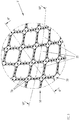
- bulges 20 are preferably defined almost all over the entire tubular body wall 10 and arranged in a sort of inclined row-column matrix. Two adjacent bulges 20 preferably define therebetween a respective channel 50.
- the channel 50 is defined by side walls 32 of two adjacent bulges 20.
- Each channel 50 is therefore preferably aligned along a direction inclined with respect to the rotational axis R.
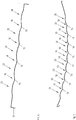
- Figure 10 shows a first different pattern obtained by bulges 20 displaced in groups G and arranged in inclined row-column spaced one to the other over the tubular body wall 110.
- Bulges 20 are preferably arranged in rows along a main axis Y.
- the main axis Y is parallel to the rotational axis R.
- Each area A may also be considered as a large channel, preferably with a width equal or larger than a corresponding row of bulges, preferably aligned along the rotational axis R.
- Figure 11 shows a second different pattern obtained by bulges 20 displaced in inclined rows H spaced one to the other over the tubular body wall 210.
- Bulges 20 are preferably arranged in rows along a main axis Y'.
- the main axis Y' is inclined with respect to the rotational axis R.
- Each area A' may also be considered as a channel, preferably with a width equal or larger than a corresponding row of bulges, preferably aligned along a direction inclined with respect to the rotational axis R.
- the tubular body wall 10 preferably comprises distributed holes 70. Holes 70 are preferably obtained by punching the tubular body wall 10.
- Holes 70 help discharging of water from inside of the washing drum 4 to the outside to centrifugally dehydrating the laundry placed therein.
- holes 70 are realized in channels 50, as better visible in Figures 3 and 5 .
- holes 70 are realized only in channels 50.
- holes 70 are differently distributed over the tubular body wall.
- holes 70 in the tubular body wall 310 are additionally or alternatively realized at side walls 32 and/or bottom walls 34 of the bulges 20.
- the bulges 20 thanks to their shape and orientation, as described above, enhances channelling away of water when the washing drum 1 rotates, either in clockwise direction C1 or counterclockwise direction C2.
- the bulges 20 thanks to their shape and orientation, as described above, offer gentle treatment of the laundry when the washing drum 1 rotates, either in clockwise direction C1 or counterclockwise direction C2.
- the height D of the side walls is preferably constant, or substantially constant, and the bottom wall 34 is preferably parallel, or substantially parallel, to the tubular body wall 10.
- the height of the side walls varies, and the bottom wall preferably is not parallel to the tubular body wall.
- the height of the side walls 32' decreases continuously and the bottom wall 34' of the bulge 20' is inclined with respect to the tubular body wall 10.
- the height of the side walls 32' decreases continuously going from the first corner K1 to the third corner K3 (as it can be deduced by comparing distances D1 and D2 depicted in Figure 8A ).
- the bottom wall 34' of the bulge 20' is therefore preferably sloped going from the first corner K1 to the third corner K3.
- mechanical treatment of the laundry is differentiated between clockwise and counterclockwise rotations of the washing drum 1.
- the present invention allows all the set objects to be achieved.
- it makes it possible to provide a washing drum increasing dehydration performance of the laundry during a washing cycle compared to known laundry washing machines.
Landscapes
- Engineering & Computer Science (AREA)
- Textile Engineering (AREA)
- Main Body Construction Of Washing Machines And Laundry Dryers (AREA)
Abstract
Description
- The present invention concerns the field of laundry washing techniques. Specifically, the invention relates to a washing drum adapted to be rotatably mounted in a laundry washing machine.
- Nowadays the use of laundry washing machines, both "simple" laundry washing machines (i.e. laundry washing machines which can only wash and rinse laundry) and laundry washing-drying machines (i.e. laundry washing machines which can also dry laundry), is widespread.
- In the present description, the term "laundry washing machine" will refer to both a simple laundry washing machine and a laundry washing-drying machine.
- Laundry washing machines generally comprise an external casing, or cabinet, provided with a washing tub which contains a washing drum where the laundry is placed. A loading/unloading door ensures access to the washing drum.
- Washing drums of known type typically comprise a substantially cylindrical wall closed at one end by a substantially flat rear wall and presenting, on its other end, an opening closed by said loading/unloading door.
- Cylindrical wall is typically provided with perforations/holes which allow the liquid flowing therethrough.
- Said holes are typically and preferably homogeneously distributed on the wall of the drum. Furthermore, the cylindrical wall is also typically provided with bulges.
- According to the known art, bulges and holes are arranged to increase the performance of the washing process.
- During the washing process, particularly when the washing drum is rotated, the laundry hits and/or is stuck against the inner surface of the drum wall and water contained in the laundry is ejected outwardly through the holes by means of the centrifugal force for centrifugally dehydrating the laundry.
- Shape of bulges may affect treatment of the laundry due to interaction with laundry.
- It is an object of the present invention to optimize the shape of the washing drum wall in order to increase dehydration performance of the laundry.
- It is another object of the invention to optimize the shape of the washing drum wall in order to obtain a gentle treatment of the laundry.
- Applicant has found that by providing a laundry washing machine comprising a washing tub external to a washing drum wherein the washing drum comprises a plurality of bulges and by providing said bulges with a squircle-shaped contour, it is possible to reach the mentioned objects.
- In a first aspect thereof the present invention relates, therefore, to a washing drum which is adapted to be rotatably mounted in a laundry washing machine wherein laundry to be washed may be placed, said washing drum comprising a tubular body wall apt to rotate around a rotational axis and said tubular body wall comprising at least one bulge protruding from said tubular body wall towards said rotational axis and at least one hole, wherein the contour of said at least one bulge at said tubular body wall has the shape of a squircle, wherein the reference axis of said squircle-shaped contour is inclined with respect to said rotational axis.
- The squircle is preferably composed by four rounded corners joined by four slightly rounded sides.
- Preferably, the reference axis divides symmetrically two opposed slightly rounded sides.
- In a preferred embodiment of the invention, the reference axis of the squircle-shaped contour is inclined with respect to the rotational axis to form an angle between 22,5° and 67,5° preferably an angle equal to 45°.
- Preferably, said at least one bulge comprises side walls extending from said contour and terminating at a bottom wall.
- According to a preferred embodiment of the invention, the washing drum comprises a plurality of bulges placed side by side, two adjacent bulges defining a channel therebetween.
- In a preferred embodiment of the invention, said at least one hole is realized in said channel.
- In a further preferred embodiment of the invention, said at least one hole is realized in said side walls and/or said bottom wall.
- Preferably, the washing drum comprises a plurality of holes.
- In a preferred embodiment of the invention, the holes are realized in the channel.
- In a further preferred embodiment of the invention, the holes are realized in the side walls and/or the bottom wall.
- According to a preferred embodiment of the invention, the side walls and/or the bottom wall are rounded shaped.
- In a preferred embodiment of the invention, the washing drum comprises a plurality of bulges, said plurality of bulges being arranged in a row along a main axis.
- In a further preferred embodiment of the invention, the washing drum comprises one or more groups of bulges, said one or more groups comprising one or more rows of bulges aligned along a main axis.
- Preferably, two of said groups are separated by a smooth area.
- Preferably, the smooth area may be considered as a channel having a width preferably equal or larger than the width of a row of bulges.
- According to a preferred embodiment of the invention, the main axis is parallel to the rotational axis.
- According to a further preferred embodiment of the invention, the main axis is inclined with respect to the rotational axis.
- In a preferred embodiment of the invention, the height of the side walls is constant.
- In a further preferred embodiment of the invention, the height of the side walls varies. Preferably, the height of said side walls decreases continuously.
- In a preferred embodiment of the invention, the bottom wall is parallel to the tubular body wall.
- In a further preferred embodiment of the invention, the bottom wall is not parallel to the tubular body wall.
- Preferably, the bottom wall is inclined with respect to the tubular body wall.
- In a further aspect thereof, the present invention concerns a laundry washing machine comprising a washing tub external to a washing drum, wherein the washing drum is realized as described above.
- Further characteristics and advantages of the present invention will be highlighted in greater detail in the following detailed description of some of its preferred embodiments, provided with reference to the enclosed drawings. In the drawings, corresponding characteristics and/or components are identified by the same reference numbers. In particular:
-
Figure 1 shows a perspective view of a washing drum according to the invention adapted to be used in a washing laundry machine; -
Figure 2 shows an element of the washing drum ofFigure 1 isolated from the rest; -
Figure 3 is an enlarged view of a detail of the washing drum shown infigure 1 ; -
Figure 4 shows a geometrical shape used for realization of the washing drum according to the invention; -
Figure 5 shows a plan view of a detail offigure 3 ; -
Figure 6 is a cross section along line VI°-VI° offigure 2 ; -
Figure 7 is a cross section along line VII°-VII° offigure 2 ; -
Figure 8 is a cross section along line VIII°-VIII° offigure 5 ; -
Figure 8A is a further preferred embodiment offigure 8 ; -
Figure 9 shows a plan view of the drum portion shown inFigure 3 , from the front point of view V indicated inFigure 3 , according to a second preferred embodiment of the invention; -
Figures 10 and11 show the washing drum ofFigure 2 according to further preferred embodiments of the invention. - The present invention has proved to be particularly advantageous when applied to laundry washing machines, as described below. It should in any case be underlined that the present invention is not limited to laundry washing machines. On the contrary, the present invention can be conveniently applied to laundry washing-drying machines (i.e. laundry washing machines which can also dry laundry).
- With reference to
Figure 1 a preferred embodiment of awashing drum 1 according to the invention which is adapted to be rotatably mounted in a laundry washing machine is shown. - The
washing drum 1 preferably comprises atubular body wall 10 apt to rotate around a rotational axis R, as better visible inFigure 2 . Thetubular body wall 10 is preferably cylindrically shaped. In different embodiments, the tubular body wall may by differently shaped, for example it may be frustum conical shaped and/or showing a rounded shape. - The
tubular body wall 10 preferably comprises a rear end 12 closed by a rear wall 12 and afront end 14 presenting an opening 16 for loading/unloading laundry and preferably aligned with a loading/unloading door of the laundry washing machine (not shown). Thetubular body wall 10 is preferably made by metallic material, preferably made of stainless steel. - The
tubular body wall 10 comprisesbulges 20 protruding from thetubular body wall 10 towards the rotational axis R. - Preferably, the
tubular body wall 10 is metallic and bulges 20 are obtained by punching thetubular body wall 10. - According to an aspect of the invention, the
contour 30 of thebulge 20 at saidtubular body wall 10 has the shape of a squircle. -
Figure 4 shows a squircle in a cartesian coordinate system x and y. The squircle is defined by the equation (x-a)4+(y-b)4=r4. - The squircle substantially shows four rounded corners K1÷K4 joined by four slightly rounded sides S1÷S4.
- The squircle is symmetrical and shows two lines of symmetry coinciding with said axis x and y. Hereinafter, it will be indicated the first line of symmetry x as a reference axis X of the squircle. It has to be noted that, due to symmetry of squircle, the reference axis as used in the present invention could indicate also the second line of symmetry y.
- In other words, the reference axis X divides symmetrically two opposed slightly rounded sides S2, S4.
- It has to be noted that actually the squircle may be roughly symmetrical rather than perfectly symmetrical, in particular due to deformation caused by the punching process.
- The
bulge 20 preferably comprisesside walls 32 extending from saidcontour 30 and terminating at abottom wall 34. - Side and
bottom walls - Side and
bottom walls - Rounded walls advantageously offer gentle treatment of the laundry.
- According to an aspect of the invention, the
bulge 20 is opportunely oriented at thetubular body wall 10 so that the reference axis X of the squircle-shapedcontour 30 is inclined with respect to the rotational axis R, as illustrated inFigure 5 . - In
Figure 5 the rotational axis R is depicted together with the preferred rotation directions C1, C2 of thewashing drum 1. - As known, in fact, during a washing cycle the
washing drum 1 is preferably rotated in clockwise C1 and counterclockwise C2 directions around the rotational axis R for centrifugally dehydrating the laundry placed therein. - Clockwise C1 and counterclockwise C2 directions are also indicated in
Figures 1 and2 . - According to an aspect of the invention, the reference axis X of the squircle-shaped
contour 30 is inclined with respect to the rotational axis R of thewashing drum 1 to form an angle A. - In a preferred embodiment of the invention, as illustrated in the Figures, the angle A is equal to 45°. Preferably, the angle is comprised between 22,5° and 67,5°.
- Preferably, the
tubular body wall 10 comprises a plurality bulges 20 placed side by side to define a desired pattern. - As illustrated in
Figure 2 , bulges 20 are preferably defined almost all over the entiretubular body wall 10 and arranged in a sort of inclined row-column matrix. Twoadjacent bulges 20 preferably define therebetween arespective channel 50. Thechannel 50 is defined byside walls 32 of twoadjacent bulges 20. - Each
channel 50 is therefore preferably aligned along a direction inclined with respect to the rotational axis R. -
Figure 10 shows a first different pattern obtained bybulges 20 displaced in groups G and arranged in inclined row-column spaced one to the other over thetubular body wall 110. -
Bulges 20 are preferably arranged in rows along a main axis Y. Preferably, the main axis Y is parallel to the rotational axis R. - Between the groups G of
bulges 20 smooth areas A are preferably defined. Each area A may also be considered as a large channel, preferably with a width equal or larger than a corresponding row of bulges, preferably aligned along the rotational axis R. -
Figure 11 shows a second different pattern obtained bybulges 20 displaced in inclined rows H spaced one to the other over thetubular body wall 210. -
Bulges 20 are preferably arranged in rows along a main axis Y'. Preferably, the main axis Y' is inclined with respect to the rotational axis R. - Between the groups H of
bulges 20 smooth areas A' are preferably defined. Each area A' may also be considered as a channel, preferably with a width equal or larger than a corresponding row of bulges, preferably aligned along a direction inclined with respect to the rotational axis R. - The
tubular body wall 10 preferably comprises distributed holes 70.Holes 70 are preferably obtained by punching thetubular body wall 10. -
Holes 70 help discharging of water from inside of the washing drum 4 to the outside to centrifugally dehydrating the laundry placed therein. - According to a preferred embodiment of the invention, holes 70 are realized in
channels 50, as better visible inFigures 3 and5 . Here, preferably, holes 70 are realized only inchannels 50. - In different embodiments, holes 70 are differently distributed over the tubular body wall. For example, as illustrated in
Figure 9 , holes 70 in thetubular body wall 310 are additionally or alternatively realized atside walls 32 and/orbottom walls 34 of thebulges 20. - According to and advantageous aspect of the invention, the
bulges 20 thanks to their shape and orientation, as described above, enhances channelling away of water when thewashing drum 1 rotates, either in clockwise direction C1 or counterclockwise direction C2. - Referring to
Figure 5 , when thewashing drum 1 rotates in clockwise direction C1, water hits the first/upper corner K1 and lateral sides S1, S2 of thebulge 20. The effect is that water is deflected from the center towards the sides of thebulge 20 alongchannels 50 betweenadjacent bulges 20, avoiding creation of turbulence and/or accumulation of water and enhancing conveyance of the water towards dischargingholes 70. - Analogously, when the
washing drum 1 rotates in counterclockwise direction C2 water hits the third/lower corner K3 and lateral sides S3, S4 of thebulge 20. The effect is that water is deflected from the center towards the sides of thebulge 20 alongchannels 50 betweenadjacent bulges 20, avoiding creation of turbulence and/or accumulation of water and enhancing conveyance of the water towards dischargingholes 70. - According to a further advantageous aspect of the invention, the
bulges 20 thanks to their shape and orientation, as described above, offer gentle treatment of the laundry when thewashing drum 1 rotates, either in clockwise direction C1 or counterclockwise direction C2. - Referring to
Figures 5 and8 , when thewashing drum 1 rotates in clockwise direction C1, laundry hits the first/upper corner K1 and lateral sides S1, S2 of thebulge 20. The effect is that laundry does not stick against the inner wall of thetubular body wall 10 but the laundry is gently detached from the same. - Analogously, when the
washing drum 1 rotates in counterclockwise direction C2, laundry hits the third/lower corner K3 and lateral sides S3, S4 of thebulge 20. The effect is that laundry does not stick against the inner wall of thetubular body wall 10 but the laundry is gently detached from the same. - In a preferred embodiment of the invention, as better visible in
Figure 8 , the height D of the side walls is preferably constant, or substantially constant, and thebottom wall 34 is preferably parallel, or substantially parallel, to thetubular body wall 10. - In further preferred embodiments of the invention, the height of the side walls varies, and the bottom wall preferably is not parallel to the tubular body wall.
- For example, as illustrated in the embodiment of
Figure 8A , the height of the side walls 32' decreases continuously and the bottom wall 34' of the bulge 20' is inclined with respect to thetubular body wall 10. - Preferably, the height of the side walls 32' decreases continuously going from the first corner K1 to the third corner K3 (as it can be deduced by comparing distances D1 and D2 depicted in
Figure 8A ). The bottom wall 34' of the bulge 20' is therefore preferably sloped going from the first corner K1 to the third corner K3. - The effect of this shape is that the laundry is detached differently when the when the
washing drum 1 rotates in clockwise direction C1 or in counterclockwise direction C2. - Advantageously, mechanical treatment of the laundry is differentiated between clockwise and counterclockwise rotations of the
washing drum 1. - It has thus been shown that the present invention allows all the set objects to be achieved. In particular, it makes it possible to provide a washing drum increasing dehydration performance of the laundry during a washing cycle compared to known laundry washing machines.
- While the present invention has been described with reference to the particular embodiments shown in the figures, it should be noted that the present invention is not limited to the specific embodiments illustrated and described herein; on the contrary, further variants of the embodiments described herein fall within the scope of the present invention, which is defined in the claims.
Claims (15)
- A washing drum (1) which is adapted to be rotatably mounted in a laundry washing machine wherein laundry to be washed may be placed, said washing drum (1) comprising a tubular body wall (10; 110; 210) apt to rotate around a rotational axis (R) and said tubular body wall (10; 110; 210) comprising at least one bulge (20; 20') protruding from said tubular body wall (10; 110; 210) towards said rotational axis (R) and at least one hole (70), characterized in that the contour of said at least one bulge (20; 20') at said tubular body wall (10; 110; 210) has the shape of a squircle, wherein the reference axis (X) of said squircle-shaped contour is inclined with respect to said rotational axis (R).
- A washing drum (1) according to claim 1, characterized in that said reference axis (X) of said squircle-shaped contour is inclined with respect to said rotational axis (R) to form an angle between 22,5° and 67,5° preferably an angle equal to 45°.
- A washing drum (1) according to claim 1 or 2, characterized in that said at least one bulge (20; 20') comprises side walls (32; 32') extending from said contour and terminating at a bottom wall (34; 34').
- A washing drum (1) according to any of the preceding claims, characterized in that it comprises a plurality of said at least one bulge (20; 20') placed side by side, two adjacent bulges (20; 20') defining a channel (50; A; A') therebetween.
- A washing drum (1) according to claim 4, characterized in that said at least one hole (70) is realized in said channel (50).
- A washing drum (1) according to any of the claims 3 to 5, characterized in that said at least one hole (70) is realized in said side walls (32; 32') and/or said bottom wall (34; 34').
- A washing drum (1) according to any of the claims 3 to 6, characterized in that said side walls (32; 32') and/or said bottom wall (34; 34') are rounded shaped.
- A washing drum (1) according to any of the preceding claims, characterized in that it comprises a plurality of said at least one bulge (20; 20'), said plurality of bulges (20; 20') being arranged in a row along a main axis (Y; Y').
- A washing drum (1) according to any of the claims 1 to 7, characterized in that it comprises one or more groups (G; H) of bulges (20; 20'), said one or more groups (G; H) comprising one or more rows of bulges (20; 20') aligned along a main axis (Y; Y').
- A washing drum (1) according to claim 9, characterized in that two groups (G; H) of said one or more groups (G; H) are separated by a smooth area (A; A').
- A washing drum (1) according to any of the claims 8 to 10, characterized in that said main axis (Y) is parallel to said rotational axis (R).
- A washing drum (1) according to any of the claims 8 to 10, characterized in that said main axis (Y') is inclined with respect to said rotational axis (R).
- A washing drum (1) according to any of the claims 3 to 12, characterized in that the height (D) of said side walls (32) is constant.
- A washing drum (1) according to any of the claims 3 to 12, characterized in that the height of said side walls (32') varies.
- A laundry washing machine comprising a washing tub external to a washing drum (1), characterized in that said washing drum (1) is realized according to any of the preceding claims.
Priority Applications (5)
| Application Number | Priority Date | Filing Date | Title |
|---|---|---|---|
| PL19165272.6T PL3715522T3 (en) | 2019-03-26 | 2019-03-26 | Washing drum for a laundry washing machine and laundry washing machine equipped with such drum |
| EP19165272.6A EP3715522B1 (en) | 2019-03-26 | 2019-03-26 | Washing drum for a laundry washing machine and laundry washing machine equipped with such drum |
| AU2020201474A AU2020201474B2 (en) | 2019-03-26 | 2020-02-28 | Washing drum for a laundry washing machine and laundry washing machine equipped with such drum |
| CN202010213586.5A CN111748961B (en) | 2019-03-26 | 2020-03-24 | Washing drum for washing machine and washing machine equipped with the same |
| US16/828,299 US20200308752A1 (en) | 2019-03-26 | 2020-03-24 | Washing drum for a laundry washing machine and laundry washing machine equipped with such drum |
Applications Claiming Priority (1)
| Application Number | Priority Date | Filing Date | Title |
|---|---|---|---|
| EP19165272.6A EP3715522B1 (en) | 2019-03-26 | 2019-03-26 | Washing drum for a laundry washing machine and laundry washing machine equipped with such drum |
Publications (2)
| Publication Number | Publication Date |
|---|---|
| EP3715522A1 true EP3715522A1 (en) | 2020-09-30 |
| EP3715522B1 EP3715522B1 (en) | 2022-05-11 |
Family
ID=65991653
Family Applications (1)
| Application Number | Title | Priority Date | Filing Date |
|---|---|---|---|
| EP19165272.6A Active EP3715522B1 (en) | 2019-03-26 | 2019-03-26 | Washing drum for a laundry washing machine and laundry washing machine equipped with such drum |
Country Status (5)
| Country | Link |
|---|---|
| US (1) | US20200308752A1 (en) |
| EP (1) | EP3715522B1 (en) |
| CN (1) | CN111748961B (en) |
| AU (1) | AU2020201474B2 (en) |
| PL (1) | PL3715522T3 (en) |
Cited By (2)
| Publication number | Priority date | Publication date | Assignee | Title |
|---|---|---|---|---|
| CN114850316A (en) * | 2021-02-03 | 2022-08-05 | Bsh家用电器有限公司 | Method for producing a housing wall, housing wall of a laundry drum and laundry drum |
| CN114850299A (en) * | 2021-02-03 | 2022-08-05 | Bsh家用电器有限公司 | Method for producing a laundry drum and laundry drum |
Citations (4)
| Publication number | Priority date | Publication date | Assignee | Title |
|---|---|---|---|---|
| EP1028189A2 (en) * | 1999-02-10 | 2000-08-16 | BSH Bosch und Siemens Hausgeräte GmbH | Laundry washing machine with a drum having a structured surface |
| EP1925704A1 (en) * | 2006-11-24 | 2008-05-28 | Whirlpool Corporation | Drum for a washing machine and washing machine provided with such drum |
| WO2013030394A2 (en) * | 2011-09-02 | 2013-03-07 | Arcelik Anonim Sirketi | A laundry washing or laundry washing-drying machine drum |
| DE102012204560A1 (en) * | 2012-03-22 | 2013-09-26 | BSH Bosch und Siemens Hausgeräte GmbH | Laundry drum with a structure pattern and laundry treatment machine with such a laundry drum |
Family Cites Families (19)
| Publication number | Priority date | Publication date | Assignee | Title |
|---|---|---|---|---|
| JP2738957B2 (en) * | 1989-06-16 | 1998-04-08 | 三菱重工業株式会社 | Drum type washing machine |
| IT1259238B (en) * | 1992-12-07 | 1996-03-11 | Zanussi Elettrodomestici | WASHING MACHINE WITH PERFECTED PLASTIC TANK. |
| IT1282930B1 (en) * | 1995-10-13 | 1998-04-01 | Electrolux Zanussi Elettrodome | WASHING MACHINE WITH PERFECT DYNAMIC BALANCING DEVICE |
| DE19860529A1 (en) * | 1998-12-30 | 2000-07-06 | Boewe Garment Care Systems Gmb | Cleaning, post-treatment and drying of textiles, leather and furs uses cleaning machine with drum with asymmetrical ribs |
| KR100797463B1 (en) * | 2001-10-23 | 2008-01-24 | 엘지전자 주식회사 | Drum washing machine |
| KR20100030064A (en) * | 2008-09-09 | 2010-03-18 | 삼성전자주식회사 | Drum type washing machine |
| EP2372010B1 (en) * | 2010-04-01 | 2016-09-21 | Electrolux Home Products Corporation N.V. | Rotatable drum for laundry washing machines and assembly method of the rotatable drum |
| DE102011083015B4 (en) * | 2011-09-20 | 2019-08-14 | BSH Hausgeräte GmbH | Laundry drum with drum profile for optimized spin effect |
| KR101944366B1 (en) * | 2012-10-10 | 2019-02-07 | 삼성전자주식회사 | Washing Machine |
| KR102053143B1 (en) * | 2013-04-30 | 2019-12-06 | 엘지전자 주식회사 | A washing machine |
| EP2832916B1 (en) * | 2013-07-31 | 2018-03-07 | Electrolux Appliances Aktiebolag | Laundry treating machine including a rotatable drum |
| CN104420124B (en) * | 2013-08-29 | 2018-05-22 | 青岛海尔滚筒洗衣机有限公司 | A kind of washing machine inner tub and washing machine |
| CN104947373B (en) * | 2014-03-24 | 2018-12-25 | 青岛海尔洗衣机有限公司 | A kind of attached block structure of washing machine inner tub |
| WO2016180371A1 (en) * | 2015-05-13 | 2016-11-17 | 海尔亚洲株式会社 | Washing machine |
| CN203977154U (en) * | 2014-06-20 | 2014-12-03 | 无锡小天鹅股份有限公司 | Washing machine and inner core thereof |
| CN204385478U (en) * | 2014-12-03 | 2015-06-10 | 无锡小天鹅股份有限公司 | For inner core and the roller washing machine of roller washing machine |
| EP3124675B1 (en) * | 2015-07-27 | 2026-04-22 | Electrolux Appliances Aktiebolag | Washing and/or drying appliance |
| EP3378983B1 (en) * | 2017-03-20 | 2021-05-12 | Electrolux Appliances Aktiebolag | Laundry washing machine equipped with a bearing assembly for the washing drum |
| CN207295246U (en) * | 2017-08-23 | 2018-05-01 | 上海仕操洗涤有限公司 | A kind of hospital drum washing device |
-
2019
- 2019-03-26 EP EP19165272.6A patent/EP3715522B1/en active Active
- 2019-03-26 PL PL19165272.6T patent/PL3715522T3/en unknown
-
2020
- 2020-02-28 AU AU2020201474A patent/AU2020201474B2/en active Active
- 2020-03-24 US US16/828,299 patent/US20200308752A1/en not_active Abandoned
- 2020-03-24 CN CN202010213586.5A patent/CN111748961B/en active Active
Patent Citations (4)
| Publication number | Priority date | Publication date | Assignee | Title |
|---|---|---|---|---|
| EP1028189A2 (en) * | 1999-02-10 | 2000-08-16 | BSH Bosch und Siemens Hausgeräte GmbH | Laundry washing machine with a drum having a structured surface |
| EP1925704A1 (en) * | 2006-11-24 | 2008-05-28 | Whirlpool Corporation | Drum for a washing machine and washing machine provided with such drum |
| WO2013030394A2 (en) * | 2011-09-02 | 2013-03-07 | Arcelik Anonim Sirketi | A laundry washing or laundry washing-drying machine drum |
| DE102012204560A1 (en) * | 2012-03-22 | 2013-09-26 | BSH Bosch und Siemens Hausgeräte GmbH | Laundry drum with a structure pattern and laundry treatment machine with such a laundry drum |
Cited By (3)
| Publication number | Priority date | Publication date | Assignee | Title |
|---|---|---|---|---|
| CN114850316A (en) * | 2021-02-03 | 2022-08-05 | Bsh家用电器有限公司 | Method for producing a housing wall, housing wall of a laundry drum and laundry drum |
| CN114850299A (en) * | 2021-02-03 | 2022-08-05 | Bsh家用电器有限公司 | Method for producing a laundry drum and laundry drum |
| EP4039860A1 (en) * | 2021-02-03 | 2022-08-10 | BSH Hausgeräte GmbH | Laundry drum and method for manufacturing a laundry drum with positionally accurate positioning of an embossing structure and flooding holes relative to each other |
Also Published As
| Publication number | Publication date |
|---|---|
| CN111748961A (en) | 2020-10-09 |
| PL3715522T3 (en) | 2022-09-12 |
| AU2020201474A1 (en) | 2020-10-15 |
| AU2020201474B2 (en) | 2025-09-11 |
| EP3715522B1 (en) | 2022-05-11 |
| CN111748961B (en) | 2024-01-19 |
| US20200308752A1 (en) | 2020-10-01 |
Similar Documents
| Publication | Publication Date | Title |
|---|---|---|
| US7661203B2 (en) | Basket for washing machine, washer-dryer, and the like | |
| EP2363524B1 (en) | Drum paddle for a washing machine | |
| CN101189382A (en) | Water-circulating domestic appliance with an embossed washing drum | |
| CN103820973B (en) | Washing machine | |
| US9951453B2 (en) | Washing machine and method of manufacturing washing tub being provided therein | |
| US7373793B2 (en) | Damper assembly and washing machine using the same | |
| US20200308752A1 (en) | Washing drum for a laundry washing machine and laundry washing machine equipped with such drum | |
| EP1925704B1 (en) | Drum for a washing machine and washing machine provided with such drum | |
| KR102742321B1 (en) | Drum type laundry apparatus | |
| EP2580384B1 (en) | A washing machine | |
| US7997104B2 (en) | Laundry drum | |
| US9458563B2 (en) | Front loading washer baffle | |
| US3307383A (en) | Agitator with controlled vane flexure | |
| EP1876282A1 (en) | Basket for washing or drying machines | |
| CN107849781A (en) | Washing machine | |
| PT1913191E (en) | Laundry washing or washing/drying machine with rejector device | |
| GB2268939A (en) | Cellular washing machine drum | |
| US9115458B2 (en) | Washer/dryer | |
| US2974514A (en) | Laundry machine | |
| EP4377507A1 (en) | A drum for household appliances | |
| JP5898598B2 (en) | Washing machine | |
| EP2325367A1 (en) | A drum for washing machines and tumble dryers | |
| US7624602B2 (en) | Cored vane for an agitating device | |
| KR20170006091A (en) | Laundry treat machine | |
| JPH01115398A (en) | Washer of drum type |
Legal Events
| Date | Code | Title | Description |
|---|---|---|---|
| PUAI | Public reference made under article 153(3) epc to a published international application that has entered the european phase |
Free format text: ORIGINAL CODE: 0009012 |
|
| STAA | Information on the status of an ep patent application or granted ep patent |
Free format text: STATUS: THE APPLICATION HAS BEEN PUBLISHED |
|
| AK | Designated contracting states |
Kind code of ref document: A1 Designated state(s): AL AT BE BG CH CY CZ DE DK EE ES FI FR GB GR HR HU IE IS IT LI LT LU LV MC MK MT NL NO PL PT RO RS SE SI SK SM TR |
|
| AX | Request for extension of the european patent |
Extension state: BA ME |
|
| STAA | Information on the status of an ep patent application or granted ep patent |
Free format text: STATUS: REQUEST FOR EXAMINATION WAS MADE |
|
| 17P | Request for examination filed |
Effective date: 20210330 |
|
| RBV | Designated contracting states (corrected) |
Designated state(s): AL AT BE BG CH CY CZ DE DK EE ES FI FR GB GR HR HU IE IS IT LI LT LU LV MC MK MT NL NO PL PT RO RS SE SI SK SM TR |
|
| RIC1 | Information provided on ipc code assigned before grant |
Ipc: D06F 37/02 20060101AFI20210818BHEP |
|
| GRAP | Despatch of communication of intention to grant a patent |
Free format text: ORIGINAL CODE: EPIDOSNIGR1 |
|
| STAA | Information on the status of an ep patent application or granted ep patent |
Free format text: STATUS: GRANT OF PATENT IS INTENDED |
|
| INTG | Intention to grant announced |
Effective date: 20211020 |
|
| GRAS | Grant fee paid |
Free format text: ORIGINAL CODE: EPIDOSNIGR3 |
|
| GRAA | (expected) grant |
Free format text: ORIGINAL CODE: 0009210 |
|
| STAA | Information on the status of an ep patent application or granted ep patent |
Free format text: STATUS: THE PATENT HAS BEEN GRANTED |
|
| AK | Designated contracting states |
Kind code of ref document: B1 Designated state(s): AL AT BE BG CH CY CZ DE DK EE ES FI FR GB GR HR HU IE IS IT LI LT LU LV MC MK MT NL NO PL PT RO RS SE SI SK SM TR |
|
| REG | Reference to a national code |
Ref country code: GB Ref legal event code: FG4D |
|
| REG | Reference to a national code |
Ref country code: CH Ref legal event code: EP |
|
| REG | Reference to a national code |
Ref country code: AT Ref legal event code: REF Ref document number: 1491504 Country of ref document: AT Kind code of ref document: T Effective date: 20220515 |
|
| REG | Reference to a national code |
Ref country code: DE Ref legal event code: R096 Ref document number: 602019014733 Country of ref document: DE |
|
| REG | Reference to a national code |
Ref country code: IE Ref legal event code: FG4D |
|
| REG | Reference to a national code |
Ref country code: LT Ref legal event code: MG9D |
|
| REG | Reference to a national code |
Ref country code: NL Ref legal event code: MP Effective date: 20220511 |
|
| REG | Reference to a national code |
Ref country code: AT Ref legal event code: MK05 Ref document number: 1491504 Country of ref document: AT Kind code of ref document: T Effective date: 20220511 |
|
| PG25 | Lapsed in a contracting state [announced via postgrant information from national office to epo] |
Ref country code: SE Free format text: LAPSE BECAUSE OF FAILURE TO SUBMIT A TRANSLATION OF THE DESCRIPTION OR TO PAY THE FEE WITHIN THE PRESCRIBED TIME-LIMIT Effective date: 20220511 Ref country code: PT Free format text: LAPSE BECAUSE OF FAILURE TO SUBMIT A TRANSLATION OF THE DESCRIPTION OR TO PAY THE FEE WITHIN THE PRESCRIBED TIME-LIMIT Effective date: 20220912 Ref country code: NO Free format text: LAPSE BECAUSE OF FAILURE TO SUBMIT A TRANSLATION OF THE DESCRIPTION OR TO PAY THE FEE WITHIN THE PRESCRIBED TIME-LIMIT Effective date: 20220811 Ref country code: NL Free format text: LAPSE BECAUSE OF FAILURE TO SUBMIT A TRANSLATION OF THE DESCRIPTION OR TO PAY THE FEE WITHIN THE PRESCRIBED TIME-LIMIT Effective date: 20220511 Ref country code: LT Free format text: LAPSE BECAUSE OF FAILURE TO SUBMIT A TRANSLATION OF THE DESCRIPTION OR TO PAY THE FEE WITHIN THE PRESCRIBED TIME-LIMIT Effective date: 20220511 Ref country code: HR Free format text: LAPSE BECAUSE OF FAILURE TO SUBMIT A TRANSLATION OF THE DESCRIPTION OR TO PAY THE FEE WITHIN THE PRESCRIBED TIME-LIMIT Effective date: 20220511 Ref country code: GR Free format text: LAPSE BECAUSE OF FAILURE TO SUBMIT A TRANSLATION OF THE DESCRIPTION OR TO PAY THE FEE WITHIN THE PRESCRIBED TIME-LIMIT Effective date: 20220812 Ref country code: FI Free format text: LAPSE BECAUSE OF FAILURE TO SUBMIT A TRANSLATION OF THE DESCRIPTION OR TO PAY THE FEE WITHIN THE PRESCRIBED TIME-LIMIT Effective date: 20220511 Ref country code: ES Free format text: LAPSE BECAUSE OF FAILURE TO SUBMIT A TRANSLATION OF THE DESCRIPTION OR TO PAY THE FEE WITHIN THE PRESCRIBED TIME-LIMIT Effective date: 20220511 Ref country code: BG Free format text: LAPSE BECAUSE OF FAILURE TO SUBMIT A TRANSLATION OF THE DESCRIPTION OR TO PAY THE FEE WITHIN THE PRESCRIBED TIME-LIMIT Effective date: 20220811 Ref country code: AT Free format text: LAPSE BECAUSE OF FAILURE TO SUBMIT A TRANSLATION OF THE DESCRIPTION OR TO PAY THE FEE WITHIN THE PRESCRIBED TIME-LIMIT Effective date: 20220511 |
|
| PG25 | Lapsed in a contracting state [announced via postgrant information from national office to epo] |
Ref country code: RS Free format text: LAPSE BECAUSE OF FAILURE TO SUBMIT A TRANSLATION OF THE DESCRIPTION OR TO PAY THE FEE WITHIN THE PRESCRIBED TIME-LIMIT Effective date: 20220511 Ref country code: LV Free format text: LAPSE BECAUSE OF FAILURE TO SUBMIT A TRANSLATION OF THE DESCRIPTION OR TO PAY THE FEE WITHIN THE PRESCRIBED TIME-LIMIT Effective date: 20220511 Ref country code: IS Free format text: LAPSE BECAUSE OF FAILURE TO SUBMIT A TRANSLATION OF THE DESCRIPTION OR TO PAY THE FEE WITHIN THE PRESCRIBED TIME-LIMIT Effective date: 20220911 |
|
| PG25 | Lapsed in a contracting state [announced via postgrant information from national office to epo] |
Ref country code: SM Free format text: LAPSE BECAUSE OF FAILURE TO SUBMIT A TRANSLATION OF THE DESCRIPTION OR TO PAY THE FEE WITHIN THE PRESCRIBED TIME-LIMIT Effective date: 20220511 Ref country code: SK Free format text: LAPSE BECAUSE OF FAILURE TO SUBMIT A TRANSLATION OF THE DESCRIPTION OR TO PAY THE FEE WITHIN THE PRESCRIBED TIME-LIMIT Effective date: 20220511 Ref country code: RO Free format text: LAPSE BECAUSE OF FAILURE TO SUBMIT A TRANSLATION OF THE DESCRIPTION OR TO PAY THE FEE WITHIN THE PRESCRIBED TIME-LIMIT Effective date: 20220511 Ref country code: EE Free format text: LAPSE BECAUSE OF FAILURE TO SUBMIT A TRANSLATION OF THE DESCRIPTION OR TO PAY THE FEE WITHIN THE PRESCRIBED TIME-LIMIT Effective date: 20220511 Ref country code: DK Free format text: LAPSE BECAUSE OF FAILURE TO SUBMIT A TRANSLATION OF THE DESCRIPTION OR TO PAY THE FEE WITHIN THE PRESCRIBED TIME-LIMIT Effective date: 20220511 Ref country code: CZ Free format text: LAPSE BECAUSE OF FAILURE TO SUBMIT A TRANSLATION OF THE DESCRIPTION OR TO PAY THE FEE WITHIN THE PRESCRIBED TIME-LIMIT Effective date: 20220511 |
|
| REG | Reference to a national code |
Ref country code: DE Ref legal event code: R097 Ref document number: 602019014733 Country of ref document: DE |
|
| PLBE | No opposition filed within time limit |
Free format text: ORIGINAL CODE: 0009261 |
|
| STAA | Information on the status of an ep patent application or granted ep patent |
Free format text: STATUS: NO OPPOSITION FILED WITHIN TIME LIMIT |
|
| PG25 | Lapsed in a contracting state [announced via postgrant information from national office to epo] |
Ref country code: AL Free format text: LAPSE BECAUSE OF FAILURE TO SUBMIT A TRANSLATION OF THE DESCRIPTION OR TO PAY THE FEE WITHIN THE PRESCRIBED TIME-LIMIT Effective date: 20220511 |
|
| 26N | No opposition filed |
Effective date: 20230214 |
|
| PG25 | Lapsed in a contracting state [announced via postgrant information from national office to epo] |
Ref country code: SI Free format text: LAPSE BECAUSE OF FAILURE TO SUBMIT A TRANSLATION OF THE DESCRIPTION OR TO PAY THE FEE WITHIN THE PRESCRIBED TIME-LIMIT Effective date: 20220511 |
|
| P01 | Opt-out of the competence of the unified patent court (upc) registered |
Effective date: 20230625 |
|
| PG25 | Lapsed in a contracting state [announced via postgrant information from national office to epo] |
Ref country code: MC Free format text: LAPSE BECAUSE OF FAILURE TO SUBMIT A TRANSLATION OF THE DESCRIPTION OR TO PAY THE FEE WITHIN THE PRESCRIBED TIME-LIMIT Effective date: 20220511 |
|
| REG | Reference to a national code |
Ref country code: CH Ref legal event code: PL |
|
| GBPC | Gb: european patent ceased through non-payment of renewal fee |
Effective date: 20230326 |
|
| REG | Reference to a national code |
Ref country code: BE Ref legal event code: MM Effective date: 20230331 |
|
| PG25 | Lapsed in a contracting state [announced via postgrant information from national office to epo] |
Ref country code: LU Free format text: LAPSE BECAUSE OF NON-PAYMENT OF DUE FEES Effective date: 20230326 |
|
| REG | Reference to a national code |
Ref country code: IE Ref legal event code: MM4A |
|
| PG25 | Lapsed in a contracting state [announced via postgrant information from national office to epo] |
Ref country code: GB Free format text: LAPSE BECAUSE OF NON-PAYMENT OF DUE FEES Effective date: 20230326 |
|
| PG25 | Lapsed in a contracting state [announced via postgrant information from national office to epo] |
Ref country code: LI Free format text: LAPSE BECAUSE OF NON-PAYMENT OF DUE FEES Effective date: 20230331 Ref country code: IE Free format text: LAPSE BECAUSE OF NON-PAYMENT OF DUE FEES Effective date: 20230326 Ref country code: GB Free format text: LAPSE BECAUSE OF NON-PAYMENT OF DUE FEES Effective date: 20230326 Ref country code: FR Free format text: LAPSE BECAUSE OF NON-PAYMENT OF DUE FEES Effective date: 20230331 Ref country code: CH Free format text: LAPSE BECAUSE OF NON-PAYMENT OF DUE FEES Effective date: 20230331 |
|
| PG25 | Lapsed in a contracting state [announced via postgrant information from national office to epo] |
Ref country code: BE Free format text: LAPSE BECAUSE OF NON-PAYMENT OF DUE FEES Effective date: 20230331 |
|
| PG25 | Lapsed in a contracting state [announced via postgrant information from national office to epo] |
Ref country code: BG Free format text: LAPSE BECAUSE OF FAILURE TO SUBMIT A TRANSLATION OF THE DESCRIPTION OR TO PAY THE FEE WITHIN THE PRESCRIBED TIME-LIMIT Effective date: 20220511 |
|
| PG25 | Lapsed in a contracting state [announced via postgrant information from national office to epo] |
Ref country code: BG Free format text: LAPSE BECAUSE OF FAILURE TO SUBMIT A TRANSLATION OF THE DESCRIPTION OR TO PAY THE FEE WITHIN THE PRESCRIBED TIME-LIMIT Effective date: 20220511 |
|
| PG25 | Lapsed in a contracting state [announced via postgrant information from national office to epo] |
Ref country code: CY Free format text: LAPSE BECAUSE OF FAILURE TO SUBMIT A TRANSLATION OF THE DESCRIPTION OR TO PAY THE FEE WITHIN THE PRESCRIBED TIME-LIMIT; INVALID AB INITIO Effective date: 20190326 |
|
| PG25 | Lapsed in a contracting state [announced via postgrant information from national office to epo] |
Ref country code: HU Free format text: LAPSE BECAUSE OF FAILURE TO SUBMIT A TRANSLATION OF THE DESCRIPTION OR TO PAY THE FEE WITHIN THE PRESCRIBED TIME-LIMIT; INVALID AB INITIO Effective date: 20190326 |
|
| PG25 | Lapsed in a contracting state [announced via postgrant information from national office to epo] |
Ref country code: TR Free format text: LAPSE BECAUSE OF FAILURE TO SUBMIT A TRANSLATION OF THE DESCRIPTION OR TO PAY THE FEE WITHIN THE PRESCRIBED TIME-LIMIT Effective date: 20220511 |
|
| PGFP | Annual fee paid to national office [announced via postgrant information from national office to epo] |
Ref country code: DE Payment date: 20260320 Year of fee payment: 8 |
|
| PGFP | Annual fee paid to national office [announced via postgrant information from national office to epo] |
Ref country code: IT Payment date: 20260320 Year of fee payment: 8 |
|
| PGFP | Annual fee paid to national office [announced via postgrant information from national office to epo] |
Ref country code: PL Payment date: 20260313 Year of fee payment: 8 |