EP3715292A1 - Sheet alignment in sheet conveying device - Google Patents
Sheet alignment in sheet conveying device Download PDFInfo
- Publication number
- EP3715292A1 EP3715292A1 EP19209988.5A EP19209988A EP3715292A1 EP 3715292 A1 EP3715292 A1 EP 3715292A1 EP 19209988 A EP19209988 A EP 19209988A EP 3715292 A1 EP3715292 A1 EP 3715292A1
- Authority
- EP
- European Patent Office
- Prior art keywords
- sheet
- guide
- aligning roller
- conveying
- nip
- Prior art date
- Legal status (The legal status is an assumption and is not a legal conclusion. Google has not performed a legal analysis and makes no representation as to the accuracy of the status listed.)
- Granted
Links
Images





Classifications
-
- B—PERFORMING OPERATIONS; TRANSPORTING
- B65—CONVEYING; PACKING; STORING; HANDLING THIN OR FILAMENTARY MATERIAL
- B65H—HANDLING THIN OR FILAMENTARY MATERIAL, e.g. SHEETS, WEBS, CABLES
- B65H5/00—Feeding articles separated from piles; Feeding articles to machines
- B65H5/06—Feeding articles separated from piles; Feeding articles to machines by rollers or balls, e.g. between rollers
- B65H5/062—Feeding articles separated from piles; Feeding articles to machines by rollers or balls, e.g. between rollers between rollers or balls
-
- B—PERFORMING OPERATIONS; TRANSPORTING
- B65—CONVEYING; PACKING; STORING; HANDLING THIN OR FILAMENTARY MATERIAL
- B65H—HANDLING THIN OR FILAMENTARY MATERIAL, e.g. SHEETS, WEBS, CABLES
- B65H9/00—Registering, e.g. orientating, articles; Devices therefor
- B65H9/004—Deskewing sheet by abutting against a stop, i.e. producing a buckling of the sheet
- B65H9/006—Deskewing sheet by abutting against a stop, i.e. producing a buckling of the sheet the stop being formed by forwarding means in stand-by
-
- B—PERFORMING OPERATIONS; TRANSPORTING
- B65—CONVEYING; PACKING; STORING; HANDLING THIN OR FILAMENTARY MATERIAL
- B65H—HANDLING THIN OR FILAMENTARY MATERIAL, e.g. SHEETS, WEBS, CABLES
- B65H5/00—Feeding articles separated from piles; Feeding articles to machines
- B65H5/36—Article guides or smoothers, e.g. movable in operation
-
- B—PERFORMING OPERATIONS; TRANSPORTING
- B65—CONVEYING; PACKING; STORING; HANDLING THIN OR FILAMENTARY MATERIAL
- B65H—HANDLING THIN OR FILAMENTARY MATERIAL, e.g. SHEETS, WEBS, CABLES
- B65H9/00—Registering, e.g. orientating, articles; Devices therefor
-
- B—PERFORMING OPERATIONS; TRANSPORTING
- B65—CONVEYING; PACKING; STORING; HANDLING THIN OR FILAMENTARY MATERIAL
- B65H—HANDLING THIN OR FILAMENTARY MATERIAL, e.g. SHEETS, WEBS, CABLES
- B65H9/00—Registering, e.g. orientating, articles; Devices therefor
- B65H9/004—Deskewing sheet by abutting against a stop, i.e. producing a buckling of the sheet
- B65H9/008—Deskewing sheet by abutting against a stop, i.e. producing a buckling of the sheet the stop being formed by reversing the forwarding means
-
- B—PERFORMING OPERATIONS; TRANSPORTING
- B65—CONVEYING; PACKING; STORING; HANDLING THIN OR FILAMENTARY MATERIAL
- B65H—HANDLING THIN OR FILAMENTARY MATERIAL, e.g. SHEETS, WEBS, CABLES
- B65H2301/00—Handling processes for sheets or webs
- B65H2301/30—Orientation, displacement, position of the handled material
- B65H2301/32—Orientation of handled material
-
- B—PERFORMING OPERATIONS; TRANSPORTING
- B65—CONVEYING; PACKING; STORING; HANDLING THIN OR FILAMENTARY MATERIAL
- B65H—HANDLING THIN OR FILAMENTARY MATERIAL, e.g. SHEETS, WEBS, CABLES
- B65H2404/00—Parts for transporting or guiding the handled material
- B65H2404/10—Rollers
- B65H2404/14—Roller pairs
-
- B—PERFORMING OPERATIONS; TRANSPORTING
- B65—CONVEYING; PACKING; STORING; HANDLING THIN OR FILAMENTARY MATERIAL
- B65H—HANDLING THIN OR FILAMENTARY MATERIAL, e.g. SHEETS, WEBS, CABLES
- B65H2404/00—Parts for transporting or guiding the handled material
- B65H2404/10—Rollers
- B65H2404/15—Roller assembly, particular roller arrangement
-
- B—PERFORMING OPERATIONS; TRANSPORTING
- B65—CONVEYING; PACKING; STORING; HANDLING THIN OR FILAMENTARY MATERIAL
- B65H—HANDLING THIN OR FILAMENTARY MATERIAL, e.g. SHEETS, WEBS, CABLES
- B65H2404/00—Parts for transporting or guiding the handled material
- B65H2404/60—Other elements in face contact with handled material
- B65H2404/63—Oscillating, pivoting around an axis parallel to face of material, e.g. diverting means
-
- B—PERFORMING OPERATIONS; TRANSPORTING
- B65—CONVEYING; PACKING; STORING; HANDLING THIN OR FILAMENTARY MATERIAL
- B65H—HANDLING THIN OR FILAMENTARY MATERIAL, e.g. SHEETS, WEBS, CABLES
- B65H2404/00—Parts for transporting or guiding the handled material
- B65H2404/60—Other elements in face contact with handled material
- B65H2404/64—Other elements in face contact with handled material reciprocating perpendicularly to face of material, e.g. pushing means
-
- B—PERFORMING OPERATIONS; TRANSPORTING
- B65—CONVEYING; PACKING; STORING; HANDLING THIN OR FILAMENTARY MATERIAL
- B65H—HANDLING THIN OR FILAMENTARY MATERIAL, e.g. SHEETS, WEBS, CABLES
- B65H2404/00—Parts for transporting or guiding the handled material
- B65H2404/60—Other elements in face contact with handled material
- B65H2404/69—Other means designated for special purpose
- B65H2404/693—Retractable guiding means, i.e. between guiding and non guiding position
-
- B—PERFORMING OPERATIONS; TRANSPORTING
- B65—CONVEYING; PACKING; STORING; HANDLING THIN OR FILAMENTARY MATERIAL
- B65H—HANDLING THIN OR FILAMENTARY MATERIAL, e.g. SHEETS, WEBS, CABLES
- B65H2511/00—Dimensions; Position; Numbers; Identification; Occurrences
- B65H2511/20—Location in space
-
- B—PERFORMING OPERATIONS; TRANSPORTING
- B65—CONVEYING; PACKING; STORING; HANDLING THIN OR FILAMENTARY MATERIAL
- B65H—HANDLING THIN OR FILAMENTARY MATERIAL, e.g. SHEETS, WEBS, CABLES
- B65H2801/00—Application field
- B65H2801/03—Image reproduction devices
-
- B—PERFORMING OPERATIONS; TRANSPORTING
- B65—CONVEYING; PACKING; STORING; HANDLING THIN OR FILAMENTARY MATERIAL
- B65H—HANDLING THIN OR FILAMENTARY MATERIAL, e.g. SHEETS, WEBS, CABLES
- B65H2801/00—Application field
- B65H2801/03—Image reproduction devices
- B65H2801/06—Office-type machines, e.g. photocopiers
Definitions
- the sheet conveying device further comprises a conveying roller disposed upstream the aligning roller in the sheet conveying direction at a position where the conveying roller nips and conveys the sheet when the leading end of the sheet enters the nip.
- the sheet conveying device further comprises a motor configured to cause movement of the sheet guide, and a controller configured to control the motor to cause the sheet guide to be at the second position when the aligning roller rotates in the reverse direction for sheet alignment and at the first position when the aligning roller rotates in the forward direction for sheet conveyance.
- the sheet conveying device is configured to convey a sheet to the printer.
- a sheet processing apparatus comprising: a sheet processing device configured to process a printed sheet conveyed from a printer; and a sheet conveying device configured to convey a sheet to or from the sheet processing device, the sheet conveying device comprising: an aligning roller configured to rotate in a forward direction along a sheet conveying direction, and stop rotation or rotate in a reverse direction opposite to the forward direction to align a sheet conveyed thereto with a nip formed with the aligning roller; and a sheet guide disposed along a sheet conveyance path extending to the nip in the sheet conveying direction, and movable between a first position at which the sheet conveyance path has a first width in a thickness direction of the sheet and a second position at which the sheet conveyance path has a second width in the thickness direction less than the first width, wherein the sheet guide is at the first position when the aligning roller stops rotation or rotates in the reverse direction for sheet alignment and at the second position when the aligning roller rotates in the
- the sheet conveying device is configured to convey a sheet from the sheet processing device.
- a sheet conveying device includes an aligning roller and a sheet guide.
- the aligning roller is configured to rotate in a forward direction along a sheet conveying direction, and stop rotation or rotate in a reverse direction opposite to the forward direction to align a sheet conveyed thereto with a nip formed with the aligning roller.
- the sheet guide is disposed along a sheet conveyance path extending to the nip in the sheet conveying direction, and movable between a first position at which the sheet conveyance path has a first width in a thickness direction of the sheet and a second position at which the sheet conveyance path has a second width in the thickness direction less than the first width.
- the sheet guide is at the first position when the aligning roller stops rotation or rotates in the reverse direction for sheet alignment and at the second position when the aligning roller rotates in the forward direction for sheet conveyance.
- FIG. 1 illustrates a front view of an example of an image forming system 1 according to an embodiment.
- the image forming system 1 includes an image forming apparatus 2 and a post-processing apparatus 3.
- the image forming apparatus 2 forms an image on a sheet-like medium (hereinafter referred to as "sheet") such as paper.
- the post-processing apparatus 3 performs post-processing on sheets conveyed from the image forming apparatus 2.
- the post-processing apparatus 3 is an example of a "sheet processing apparatus".
- the image forming apparatus 2 includes a control panel 11, a scanner section 12, a printer section 13, a paper feeding section 14, a paper discharging section 15, and an image-formation control section 16.
- the control panel 11 includes various keys for receiving operation of a user. For example, the control panel 11 receives an input to select a type of the post-processing of sheets. The control panel 11 sends information corresponding to the input type of the post-processing to the post-processing apparatus 3.
- the scanner section 12 includes a reading section that reads image information of a copying target object.
- the scanner section 12 sends the read image information to the printer section 13.
- the paper discharging section 15 conveys the sheet discharged from the printer section 13 to the post-processing apparatus 3.
- the post-processing apparatus 3 is disposed adjacent to the image forming apparatus 2.
- the post-processing apparatus 3 executes, on sheets conveyed from the image forming apparatus 2, the post-processing selected through the control panel 11.
- the post-processing is stapling or sorting.
- the post-processing apparatus 3 includes a standby section 21, a processing section 22, a discharging section 23, and a post-processing control section 24.
- the sheet is conveyed from the image forming apparatus 2 to the discharging section 23.
- the processing section 22 performs the post-processing on sheets. For example, the processing section 22 aligns a plurality of sheets. The processing section 22 performs stapling on the aligned plurality of sheets. Consequently, the plurality of sheets are bound. The processing section 22 discharges the post-processed sheets to the discharging section 23.
- the discharging section 23 includes a fixed tray 23a and a movable tray 23b.
- the fixed tray 23a is provided in an upper part of the post-processing apparatus 3.
- the movable tray 23b is provided on a side of the post-processing apparatus 3. Sorted sheets can be discharged to the fixed tray 23a and the movable tray 23b.
- the post-processing control section 24 controls switching of a processing mode and a non-processing mode (a normal mode).
- the processing mode means a mode for performing the post-processing on sheets.
- the processing mode includes a sort mode and a staple mode.
- the non-processing mode means a mode for directly conveying sheets without performing the post-processing on the sheets.
- the control panel 11 includes a mode selecting section (an operation section) (not illustrated in FIG. 1 ) capable of selecting the processing mode and the non-processing mode.
- the mode selecting section is a button provided on the control panel 11. The user selects the "processing mode” and presses the button during mode selection, whereby the post-processing control section 24 causes the post-processing apparatus 3 to perform the post-processing on sheets.
- the user selects the "non-processing mode” and presses the button during the mode selection, whereby the post-processing control section 24 causes the post-processing apparatus 3 to directly discharge the sheets without performing the post-processing on the sheets.
- the image forming system 1 includes a sheet conveying device 30 (see FIG. 2 ).
- the sheet conveying device 30 is provided in the image forming apparatus 2.
- the sheet conveying device 30 is disposed between the paper feeding section 14 and the printer section 13.
- the sheet conveying device 30 corrects a tilt of a sheet conveyed from the paper feeding section 14 toward the printer section 13.
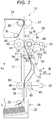
- FIG. 2 is a schematic diagram illustrating a main part of the sheet conveying device 30 according to the embodiment.
- FIG. 2 illustrates a state in which a guide 51 distal end portion is in contact with a second restricting convex section 57.
- a conveying path 31 is provided inside the image forming apparatus 2 (see FIG. 1 ).
- the sheet conveying device 30 includes an aligning mechanism 40, a conveyance-width changing mechanism 50, and a conveying mechanism 60.
- the conveying path 31 is provided along a vertical plane. A sheet is conveyed upward along the conveying path 31.
- the sheet is conveyed from the paper feeding section 14 (e.g., a paper feeding cassette 32) to the printer section 13 (e.g., an image forming section) via the sheet conveying device 30.
- the paper feeding section 14 side (the lower side on the paper surface in FIG. 2 ) in a conveying direction Vs of a sheet (hereinafter referred to as "sheet conveying direction Vs") is referred to as an "upstream side" .
- the printer section 13 side (the upper side on the paper surface in FIG. 2 ) in the sheet conveying direction Vs is referred to as a downstream side.
- first conveyance orthogonal direction V1 a direction V1 (the depth direction on the paper surface in FIG. 2 ) orthogonal to the sheet conveying direction Vs in a sheet surface of the sheet conveyed along the conveying path 31 is referred to as "first conveyance orthogonal direction V1".
- first conveyance orthogonal direction V2 a direction V2 (the left-right direction on the paper surface in FIG. 2 ) orthogonal to each of the sheet conveying direction Vs and the first conveyance orthogonal direction V1 is referred to as "second conveyance orthogonal direction V2".
- the sheet conveying device 30 includes a paper feeding cassette 32, a pickup roller 33, an intermediate transfer belt 34, a backup roller 35, a tension roller 36, and a secondary transfer roller 37.
- the paper feeding cassette 32 stores sheets S.
- the pickup roller 33 extracts the sheet S from the paper feeding cassette 32.
- the intermediate transfer belt 34, the backup roller 35, the tension roller 36, and the secondary transfer roller 37 configure the printer section 13.
- the backup roller 35 supports the intermediate transfer belt 34.
- the secondary transfer roller 37 is opposed to the backup roller 35 via the intermediate transfer belt 34.
- the conveying mechanism 60 is explained.
- the conveying roller pair 61 and 62 is disposed close to the pickup roller 33.
- the conveying roller pair 61 and 62 includes a first conveying roller 61 and a second conveying roller 62 opposed to each other.
- the first conveying roller 61 is driven by the motor 63 for sheet conveyance.
- the second conveying roller 62 rotates (is driven to rotate) according to rotation of the first conveying roller 61.
- the conveying roller pair 61 and 62 conveys a sheet supplied from the pickup roller 33 toward a downstream side of the conveying path 31.
- the conveying rollers 61 and 62 come into contact with the sheet to thereby convey the sheet when the sheet passes through a nip 44 of an aligning roller pair 41 and 42.
- the conveying rollers 61 and 62 come into contact with the sheet to thereby convey the sheet when the sheet hits against the nip 44.
- the sheet conveying device 30 further includes, a conveyance guide wall 70, a linear guide wall 71, and a curved guide wall 72.
- the conveyance guide wall 70 forms the conveying path 31 between the pickup roller 33 and the conveying roller pair 61 and 62.
- the linear guide wall 71 forms the conveying path 31 between the conveying roller pair 61 and 62 and the aligning roller pair 41 and 42.
- the linear guide wall 71 linearly extends along the sheet conveying direction Vs.
- the curved guide wall 72 forms the conveying path 31 between the curved guide wall 72 and the linear conveyance guide wall 70.
- the curved guide wall 72 forms a bending space 73 of a sheet in a position close to the conveying roller pair 61 and 62.
- the curved guide wall 72 curves to project in a direction away from the linear guide wall 71.
- FIG. 3 illustrates a view of a main part of the sheet conveying device 30 from one side in the second conveyance orthogonal direction V2 (a III arrow view of FIG. 2 ).
- the conveyance guide wall 70 and the like is omitted.
- the first conveying roller 61 is fixed to a first conveying shaft 65 (a rotating shaft) .
- Two first conveying rollers 61 are disposed at an interval along the first conveying shaft 65.
- the two first conveying rollers 61 are disposed across a first conveyance-orthogonal-direction center line C1.
- the first conveying shaft 65 linearly extends in the first conveyance orthogonal direction V1.
- the first conveying shaft 65 is longer than a sheet S in the first conveyance orthogonal direction V1. Both end portions of the first conveying shaft 65 is rotatably supported on an image forming apparatus body by a not-illustrated bearing.
- the first conveying shaft 65 is coupled to the motor for sheet conveyance 63.
- the motor 63 for sheet conveyance drives to rotate the first conveying shaft 65.
- the second conveying roller 62 is fixed to a second conveying shaft 66 (a rotating shaft) extending in parallel to the first conveying shaft 65.
- Two second conveying rollers 62 are disposed so as to be opposed to the first conveying rollers 61. Both end portions of the second conveying shaft 66 are rotatably supported on the image forming apparatus body by a not-illustrated bearing.
- reference sign L1 denotes a length of a sheet in the sheet conveying direction Vs and L2 denotes a sheet conveying path length.
- the sheet conveying path length L2 denotes a distance between a center axis of the first conveying roller 61 and a center axis of a first aligning roller 41 in the sheet conveying direction Vs.
- the sheet conveying path length L2 is shorter than the length L1 of the sheet (L2 ⁇ L1).
- the aligning mechanism 40 is explained.
- the aligning mechanism 40 includes an aligning roller pair 41 and 42 and a motor 43 for aligning.
- the aligning roller pair 41 and 42 is provided between the conveying roller pair 61 and 62 and the secondary transfer roller 37 (the backup roller 35) in the sheet conveying direction Vs.
- the aligning roller pair 41 and 42 includes a first aligning roller 41 and a second aligning roller 42 opposed to each other.
- the first aligning roller 41 and the second aligning roller 42 are in contact with each other to form the nip 44.
- the aligning mechanism 40 hits a sheet, which is conveyed along the conveying path 31, against the nip 44 to thereby align the position of the leading end of the sheet.
- the position of the leading end of the sheet means a position at a sheet downstream end in the sheet conveying direction Vs.
- the first aligning roller 41 is a driving roller driven by the motor 43 for aligning.
- the first aligning roller 41 rotates in a forward direction in an arrow R1 direction of FIG. 7 ) when the sheet passes through the nip 44.
- the first aligning roller 41 rotates in a reverse direction (in an arrow R2 direction in FIG. 6 ) opposite to the forward direction when the sheet hits against the nip 44.
- the second aligning roller 42 is a driven roller that rotates (is driven to rotate) according to the rotation of the first aligning roller 41.
- the aligning roller pair 41 and 42 conveys the sheet supplied from the conveying roller pair 61 and 62 toward the downstream side of the conveying path 31.
- the first aligning roller 41 is fixed to a first aligning shaft 45 (a rotating shaft) .
- the first aligning roller 41 extends along the first aligning shaft 45.
- the first aligning roller 41 has a symmetrical shape with the first conveyance-orthogonal-direction center line C1 as an axis of symmetry.
- the first aligning shaft 45 linearly extends in the first conveyance orthogonal direction V1.
- the first aligning roller 41 is longer than the sheet in the first conveyance orthogonal direction V1.
- the first aligning shaft 45 is longer than the first aligning roller 41 in the first conveyance orthogonal direction V1.
- Both end portions of the first aligning shaft 45 are rotatably supported on the image forming apparatus body by a not-illustrated bearing.
- the first aligning shaft 45 is coupled to the motor for aligning 43.
- the motor for aligning 43 drives to rotate the first aligning shaft 45.
- the second aligning roller 42 is fixed to a second aligning shaft 46 (a rotating shaft) extending in parallel to the first aligning shaft 45.
- One second aligning roller 42 is disposed so as to be opposed to the first aligning roller 41. Both end portions of the second aligning shaft 46 are rotatably supported on the image forming apparatus body by a not-illustrated bearing.
- the conveyance-width changing mechanism 50 is explained.
- the conveyance-width changing mechanism 50 is provided in an upstream position of the nip 44 in the sheet conveying direction Vs.
- the width of the conveying path 31 near the nip 44 is referred to as "nip vicinity conveyance width".
- the nip vicinity conveyance width is denoted by reference sign D1.
- the nip vicinity conveyance width is the width of the conveying path 31 near the nip 44 in the second conveyance orthogonal direction V2 and means an interval between the imaginary straight line and the distal end portion of the guide 51.
- the distal end portion of the guide 51 means an upstream end of the guide 51 in the sheet conveying direction Vs.
- the conveyance-width changing mechanism 50 sets the nip vicinity conveyance width when the sheet hits against the nip 44 larger than the nip vicinity conveyance width when the sheet passes through the nip 44 after hitting against the nip 44.
- the conveyance-width changing mechanism 50 includes a guide 51, position restricting sections 52 and 53, and torque transmitting and interrupting sections 54 and 55 (see FIG. 3 ).
- the guide 51 operates in accordance with the rotation of the first aligning roller 41, which is the driving roller.
- the guide 51 swings around the first aligning shaft 45.
- the guide 51 swings coaxially with the first aligning roller 41.
- a swing center of the guide 51 is coaxial with a rotation center of the first aligning roller 41.
- the guide 51 defines the nip vicinity conveyance width during reverse rotation of the first aligning roller 41 larger than the nip vicinity conveyance width during forward rotation of the first aligning roller 41.
- the guide 51 is longer than the sheet S in the first conveyance orthogonal direction V1.
- Length W2 of the guide 51 in the first conveyance orthogonal direction V1 is larger than width W1 of the sheet S in the first conveyance orthogonal direction V1 (W2>W1).
- the guide 51 includes a guide body 51a, a reinforcing rib 51b, and coupling pieces 51c.
- the guide body 51a, the reinforcing rib 51b, and the coupling pieces 51c are integrally formed by the same member.
- the guide body 51a has a plate shape extending in the first conveyance orthogonal direction V1. When viewed from the first conveyance orthogonal direction V1 (see FIG. 2 ), the guide body 51a extends outward (radial direction outward of the first aligning roller 41) from the first aligning shaft 45. Then, the guide body 51a bends and extends to separate from the conveying path 31 further outward in the radial direction.
- the reinforcing rib 51b projects to the opposite side of the conveying path 31 from a bending section of the guide body 51a. As illustrated in FIG. 3 , the reinforcing rib 51b linearly extends in the first conveyance orthogonal direction V1 over the entire guide body 51a.
- the coupling pieces 51c are respectively provided at end portions of the guide body 51a.
- the coupling pieces 51c respectively couple the end portions of the guide body 51a and the end portions of the first aligning shaft 45.
- the position restricting sections 52 and 53 include a first stopper 52 and a second stopper 53.
- the first stopper 52 is capable of coming into contact with a first end portion of the guide 51 in the first conveyance orthogonal direction V1.
- the second stopper 53 is capable of coming into contact with a second end portion of the guide 51 in the first conveyance orthogonal direction V1.
- the second end portion of the guide 51 means an end portion on the opposite side of the first end portion of the guide 51 in the first conveyance orthogonal direction V1.
- the stoppers 52 and 53 are fixed to the image forming apparatus body.
- the stoppers 52 and 53 include first restricting convex sections 56, second restricting convex sections 57, and coupling sections 58.
- the first restricting convex section 56 and the second restricting convex section 57 are disposed with an interval from each other in the second conveyance orthogonal direction V2.
- the coupling section 58 couples the first restricting convex section 56 and the second restricting convex section 57.
- the coupling section 58 extends in the second conveyance orthogonal direction V2.
- the coupling section 58 is disposed outside the guide 51 in the first conveyance orthogonal direction V1 (see FIG. 3 ).
- the first restricting convex section 56 is capable of coming into contact with a surface F1 (hereinafter referred to as "first surface F1") of the distal end portion of the guide 51 on the conveying path 31 side.
- the first restricting convex section 56 defines a terminal end in a swinging direction of the guide 51 during the forward rotation of the first aligning roller 41 (see FIG. 7 ).
- the first restricting convex section 56 restricts movement of the guide 51 during the forward rotation of the first aligning roller 41 such that the sheet can pass through the nip 44.
- the first surface F1 is formed in a linear shape extending to be closer to the linear guide wall 71 further on the downstream side in the sheet conveying direction Vs (see FIG. 7 ).
- the second restricting convex section 57 is capable of coming into contact with a surface F2 (hereinafter referred to as "second surface F2") of the distal end portion of the guide 51 on the opposite side of the conveying path 31.
- the second restricting convex section 57 defines a terminal end in the swinging direction of the guide 51 during the reverse rotation of the first aligning roller 41.
- the second restricting convex section 57 restricts movement of the guide 51 during the reverse rotation of the first aligning roller 41 such that a bending space 74 of the sheet can be formed in a position near the nip 44.
- the second surface F2 is formed in a linear shape extending to be further apart from the linear guide wall 71 further on the downstream side in the sheet conveying direction Vs.
- the torque transmitting and interrupting sections 54 and 55 disconnect the guide 51 and the first aligning shaft 45 before an overload is applied to the guide 51 and interrupt torque transmission.
- the torque transmitting and interrupting sections 54 and 55 interrupt torque transmission if the distal end portion of the guide 51 comes into contact with the first restricting convex section 56 during the forward rotation of the first aligning roller 41. Consequently, the torque transmitting and interrupting sections 54 and 55 retain a contact state of the distal end portion of the guide 51 and the first restricting convex section 56 without applying an overload to the guide 51.
- the torque transmitting and interrupting sections 54 and 55 interrupt the torque transmission when the distal end portion of the guide 51 comes into contact with the second restricting convex section 57 during the reverse rotation of the first aligning roller 41. Consequently, the torque transmitting and interrupting sections 54 and 55 retain a contact state of the distal end portion of guide 51 and the second restricting convex section 57 without applying an overload to the guide 51.
- the torque transmitting and interrupting sections 54 and 55 include a first torque limiter 54 and a second torque limiter 55.
- the first torque limiter 54 is provided at a first end portion of the first aligning shaft 45 extending in the first conveyance orthogonal direction V1.
- the second torque limiter 55 is provided at a second end portion of the first aligning shaft 45.
- the second end portion of the first aligning shaft 45 means an end portion of the first aligning shaft 45 opposite to the first end portion of the first aligning shaft 45.
- the torque limiters 54 and 55 are provided between the coupling pieces 51c of the guide 51 and the end portions of the first aligning shaft 45.
- a bend of a sheet during aligning processing of the sheet is explained.
- the following explanation is explanation of a comparative example not including the conveyance-width changing mechanism 50 according to the embodiment.
- a width direction center line Cs of the sheet S coincides with the first conveyance-orthogonal-direction center line C1.
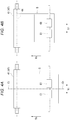
- FIGS. 5A and 5B are diagrams to explain a bend of the sheet when the sheet is obliquely tilted and conveyed in the comparative example.
- FIG. 5A illustrates a state before the sheet is conveyed into the nip.
- FIG. 5B illustrates a state in which the sheet hits against the nip and bends.
- the width direction center line Cs of the sheet S crosses the first conveyance-orthogonal-direction center line C1.
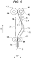
- FIG. 6 is a diagram to explain a sheet aligning operation according to an embodiment.
- the position restricting sections 52 and 53 are omitted.
- the guide 51 swings in a direction away from the linear guide wall 71 in accordance with the reverse rotation of the first aligning roller 41. Then, a second surface F2 of the distal end portion of the guide 51 comes into contact with the second restricting convex section 57 (see FIG. 2 ). Consequently, the bending space 74 of the sheet S is formed between the first surface F1 of the guide 51 distal end portion and the linear guide wall 71. That is, the bending space 74 of the sheet S sufficient for tilt correction of the sheet S is secured near the nip 44.
- the guide 51 defines the nip vicinity conveyance width during the reverse rotation of the first aligning roller 41 to be larger than the nip vicinity conveyance width during the forward rotation of the first aligning roller 41.
- the sheet S When the first conveying roller 61 rotates in a reverse direction, the sheet S hits against the nip 44. If the sheet S hits against the nip 44, the sheet S bends along the first surface F1 of the distal end portion of the guide 51. Thereafter, the sheet S bends in the space 73 between the linear guide wall 71 and the curved guide wall 72. A bend shape of the sheet S is illustrated in FIG. 6 . When viewed from the first conveyance orthogonal direction V1, the sheet S extends to be further apart from the linear guide wall 71 further on the downstream side in the sheet conveying direction Vs from the nip 44. Thereafter, the sheet S extends downward passing the downstream end of the curved guide wall 72.
- the sheet S is spaced apart from the curved guide wall 72, extends to be closer to a forming section of the linear conveying path 31 further on the downstream side in the sheet conveying direction Vs, and reaches a nip 64 of the conveying roller pair 61 and 62.
- the second face F2 of the distal end portion of the guide 51 comes into contact with the second restricting convex section 57 (see FIG. 2 ) in this way, whereby the bending space 74 of the sheet S sufficient for tilt correction of the sheet S is secured near the nip 44. For that reason, even if the sheet S is obliquely tilted and conveyed, the tilt of the sheet S can be sufficiently corrected.
- FIG. 7 is a diagram to explain the sheet conveying operation according to an embodiment.
- the position restricting sections 52 and 53 are omitted.
- the first aligning roller 41 rotates in the forward direction (the arrow R1 direction). If the first aligning roller 41 rotates in the forward direction, the guide 51 swings in a direction in which the guide 51 approaches the linear guide wall 71 in association with the forward rotation of the first aligning roller 41. Then, the first surface F1 of the guide 51 distal end portion comes into contact with the first restricting convex section 56 (see FIG. 2 ). Consequently, a bending space of the sheet S is not formed but a space 75 capable of allowing the sheet S to pass is formed between the first surface F1 of the distal end portion of the guide 51 and the linear guide wall 71. That is, the bending space 74 (see FIG. 6 ) of the sheet S sufficient for the tilt correction of the sheet S is not secured near the nip 44.
- the first conveying roller 61 maintains the forward rotation during the conveying operation of the sheet S.
- the sheet S passes through the nip 44. If the sheet S passes through the nip 44, the sheet S bends in the space 73 further on the downstream side than the distal end portion of the guide 51. That is, the sheet S bends in the space 73 between the linear guide wall 71 and the curved guide wall 72.
- a bend shape of the sheet S is illustrated in in FIG. 7 . When viewed from the first conveyance orthogonal direction V1, the sheet S linearly extends from the nip 44 along the first surface F1.
- the sheet S is spaced apart from the curved guide wall 72 and extends from the distal end portion of the guide 51 to be further apart from the linear guide wall 71 further on the downstream side in the sheet conveying direction Vs. Thereafter, the sheet S is spaced apart from the curved guide wall 72 and extends to be further apart from the linear guide wall 71 further on the downstream side in the sheet conveying direction Vs from the distal end portion of the guide 51. Thereafter, the sheet S is spaced apart from the curved guide wall 72, extends to be closer to the forming section of the linear conveying path 31 further on the downstream side in the sheet conveying direction Vs, and reaches the nip 64 of the conveying roller pair 61 and 62.
- the first surface F1 of the distal end portion of the guide 51 comes into contact with the first restricting convex section 56 (see FIG. 2 ), whereby the space 75 capable of allowing the sheet S to pass is formed between the first surface F1 of the distal end portion of the guide 51 and the linear guide wall 71.
- a bending space of the sheet S sufficient for the tilt correction of the sheet S is not secured near the nip 44.
- the bending space 73 of the sheet S is secured in a position further on the downstream side than the distal end portion of the guide 51.
- the sheet conveying device 30 includes the aligning mechanism 40 and the conveyance-width changing mechanism 50.
- the aligning mechanism 40 hits the sheet, which is conveyed along the conveying path 31, against the nip 44 to thereby align the position of the distal end of the sheet.
- the conveyance-width changing mechanism 50 is provided in the upstream position of the nip 44 in the sheet conveying direction Vs.
- the conveyance-width changing mechanism 50 defines the nip vicinity conveyance width when the sheet hits against the nip 44 to be larger than the nip vicinity conveyance width when the sheet passes through the nip 44 after hitting against the nip 44. The following effect is achieved by the configuration explained above.
- the bending space 74 of the sheet sufficient for the tilt correction of the sheet can be secured near the nip 44. For that reason, by hitting the sheet against the nip 44, it is possible to sufficiently bend the sheet and align the position of the distal end of the sheet.
- the guide 51 acts to stretch the sheets immediately before the sheet enters the nip 44. For that reason, it is possible to prevent waving of the sheet near the nip 44 and cause the sheet to pass through the nip 44 without waving. Therefore, it is possible to prevent sheet damage such as creases and folded traces from occurring in the sheet.
- the guide 51 swings coaxially with the first aligning roller 41. According to this configuration, the following effect can be achieved.
- the apparatus configuration can be simplified compared with when the guide 51 is swung around an axis different from the axis of the first aligning roller 41.
- the conveyance-width changing mechanism 50 includes the position restricting sections 52 and 53 that restrict the position of the guide 51 during the forward rotation and during the reverse rotation of the first aligning roller 41. According to this configuration, the following effect can be achieved.
- the nip vicinity conveyance width can be set to specific widths when the sheet hits against the nip 44 and when the sheet passes through the nip 44. That is, the nip vicinity conveyance width can be more stable between when the sheet hits against the nip 44 and when the sheet passes through the nip 44. Therefore, it is possible to prevent fluctuation in a correction degree of waving of the sheet and more effectively prevent sheet damage such as creases and folded traces.
- the position restricting sections 52 and 53 include the first stopper 52 and the second stopper 53.
- the first stopper 52 is capable of coming into contact with the first end portion of the guide 51 in the first conveyance orthogonal direction V1.
- the second stopper 53 is capable of coming into contact with the second end portion of the guide 51 in the first conveyance orthogonal direction V1.
- the conveying path 31 is provided along the vertical plane. According to this configuration, the following effect can be achieved. In the sheet conveying device 30 including the conveying path 31 provided along the vertical plane, it is possible to prevent sheet damage such as creases and folded traces.
- the conveying path 31 may not be provided along the vertical plane.
- FIG. 8 is a schematic diagram illustrating a main part of a sheet conveying device 130 according to a modification of the embodiment.
- a conveyance-width changing mechanism 150 may include a guide 151 provided above the conveying path 131.
- the conveyance-width changing mechanism 150 may include a support shaft 159 that swingably supports the guide 151.
- the guide 151 may swing around the support shaft 159, which is a shaft different from the first aligning roller 41 (the first aligning shaft 45).
- the guide 151 when the sheet hits against the nip 44, the guide 151 is lifted by the bent sheet S (a solid line). For that reason, it is possible to sufficiently bend the sheet S near the nip 44 and align the position of the distal end of the sheet S. On the other hand, when the sheet S passes through the nip 44, the guide 151 presses down the sheet S (a broken line) with the gravity (own weight). For that reason, it is possible to prevent waving of the sheet S near the nip 44 and cause the sheet S to pass through the nip 44 without waving. Therefore, it is possible to prevent sheet damage such as creases and folded traces.
- the sheet conveying device 30 may not be disposed between the paper feeding section 14 and the printer section 13.
- the sheet conveying device 30 may be disposed near a part where the sheet is reversed.
- the sheet conveying device 30 may be provided any applicable positions in the conveying path of the image forming system (the image forming apparatus and the post-processing apparatus).
- the guide 51 may not operate in accordance with the rotation of the first aligning roller 41.
- the guide 51 may operate individually and independently from the rotation of the first aligning roller 41.
- the sheet conveying device 30 may include a control section that controls the operation of the guide 51.
- the guide 51 may not swing.
- the guide 51 may advance and retract.
- the guide 51 may operate to define the nip vicinity conveyance width during the reverse rotation of the first aligning roller 41 to be larger than the nip vicinity conveyance width during the forward rotation of the first aligning roller 41.
- the first aligning roller 41 may not reversely rotate when the sheet hits against the nip 44.
- the first aligning roller 41 may stop when the sheet hits against the nip 44.
- the first aligning roller 41 may reversely rotate the sheet after the sheet passes through the nip 44.
- the sheet conveying device 30 may include a control section that controls the rotation of the first aligning roller 41.
- the aligning mechanism 40 may not include the aligning roller pair 41 and 42.
- the aligning mechanism 40 may include an aligning roller and a pad (a roller contact member) .
- the aligning mechanism 40 may include at least one rotating body.
- the conveying mechanism 60 may not include the conveying roller pair 61 and 62.
- the conveying mechanism 60 may include a conveying roller and a pad (a roller contact member).
- the conveying mechanism 60 may include at least one rotating body.
- the guide 51 may not be longer than the sheet in the first conveyance orthogonal direction V1.
- the guide 51 may have a length equal to or shorter than the sheet in the first conveyance orthogonal direction V1.
- a plurality of guides 51 may be disposed at an interval in the first conveyance orthogonal direction V1.
- a plurality of ribs functioning as the guides 51 may be provided with an interval in an extending direction of the plate. The number of the disposed guides 51 and disposition positions of the guides 51 may be changed according to requested specifications.
- the disposed aligning roller may not be one. Two or more aligning rollers may be disposed. The number of disposed aligning rollers and disposition positions of the aligning rollers may be changed according to requested specifications.
- the disposed conveying rollers are not limited to two. One or three or more conveying rollers may be disposed. The number of disposed conveying rollers and disposition positions of the conveying rollers may be changed according to requested specifications.
- the sheet conveying device 30 includes the aligning mechanism 40 and the conveyance-width changing mechanism 50.
- the aligning mechanism 40 causes the sheet, which is conveyed along the conveying path 31, to hit against the nip 44 to thereby align the position of the distal end of the sheet.
- the conveyance-width changing mechanism 50 is provided in the upstream position of the nip 44 in the sheet conveying direction Vs.
- the conveyance-width changing mechanism 50 defines the nip vicinity conveyance width when the sheet hits against the nip 44 to be larger than the nip vicinity conveyance width when the sheet passes through the nip 44 after hitting against the nip 44. According to the configuration explained above, the following effect can be achieved.
- the guide 51 acts to stretch the sheets immediately before the sheets enter the nip 44. For that reason, it is possible to prevent waving of the sheet near the nip 44 and cause the sheet to pass through the nip 44 without waving. Therefore, it is possible to prevent sheet damage such as creases and folded traces.
Landscapes
- Engineering & Computer Science (AREA)
- Mechanical Engineering (AREA)
- Registering Or Overturning Sheets (AREA)
Abstract
Description
- Embodiments described herein relate generally to sheet alignment in a sheet conveying device and an image forming system having the same.
- An image forming system (e.g., an MFP) includes a sheet conveying device that conveys a sheet along a conveying path. The sheet conveying device may include an aligning mechanism that performs alignment processing for correcting a tilt of the sheet conveyed along the conveying path. For example, the aligning mechanism may perform the aligning processing by causing the sheet to hit against a nip of a pair of stopped rollers and bending the sheet. However, if the skew of the sheet is too large during the aligning processing, the sheet may generate wave in a direction different from the sheet conveying direction when the sheet is bent. If the sheet is conveyed by the pair of rollers in a state in which the sheet waves in that manner, sheet damage such as creases and folded traces is likely to occur in the sheet.
- One of the objects of the present invention is to improve prior art techniques and overcome at least some of the prior art problems as for instance above illustrated.
- According to a fist aspect of the present invention, it is provided a sheet conveying device comprising: an aligning roller configured to rotate in a forward direction along a sheet conveying direction, and stop rotation or rotate in a reverse direction opposite to the forward direction to align a sheet conveyed to a nip formed with the aligning roller; and a sheet guide disposed along a sheet conveyance path extending to the nip in the sheet conveying direction, and movable between a first position at which the sheet conveyance path has a first width in a thickness direction of the sheet and a second position at which the sheet conveyance path has a second width in the thickness direction less than the first width, wherein the sheet guide is at the first position when the aligning roller stops rotation or rotates in the reverse direction for sheet alignment and at the second position when the aligning roller rotates in the forward direction for sheet conveyance.
- Optionally, the sheet conveying device according to the first aspect of the present invention further comprises a first stopper positioned to restrict movement of the sheet guide further than the first position; and a second stopper positioned to restrict movement of the sheet guide further than the second position.
- Optionally, the sheet conveying device according to the first aspect of the present invention further comprises a conveying roller disposed upstream the aligning roller in the sheet conveying direction at a position where the conveying roller nips and conveys the sheet when the leading end of the sheet enters the nip.
- Optionally, the sheet conveying device according to the first aspect of the present invention further comprises a first stationary sheet guide disposed between the conveying roller and the aligning roller along the sheet conveyance path and having a flat surface; and a second stationary sheet guide facing the first stationary sheet guide and having a curved surface protruding away from the sheet conveyance path.
- Optionally, in the sheet conveying device according to the first aspect of the present invention, the second stationary sheet guide is disposed on a same side of the sheet conveyance path as the sheet guide.
- Optionally, in the sheet conveying device according to the first aspect of the present invention, the sheet guide is attached to the aligning roller, and moves to the second position in accordance with rotation of the aligning roller in the forward direction.
- Optionally, in the sheet conveying device according to the first aspect of the present invention, the aligning roller rotates in the reverse direction for sheet alignment, and the sheet guide is attached to the aligning roller, and moves to the first position in accordance with rotation of the aligning roller in the reverse direction.
- Optionally, in the sheet conveying device according to the first aspect of the present invention, the sheet guide is movable independently of rotation of the aligning roller.
- Optionally, in the sheet conveying device according to the first aspect of the present invention, the sheet conveyance path extends along a gravity direction.
- Optionally, in the sheet conveying device according to the first aspect of the present invention, the sheet conveyance path extends along a horizontal direction and the sheet guide is disposed above the sheet conveyance path.
- Optionally, the sheet conveying device according to the first aspect of the present invention further comprises a motor configured to cause movement of the sheet guide, and a controller configured to control the motor to cause the sheet guide to be at the second position when the aligning roller rotates in the reverse direction for sheet alignment and at the first position when the aligning roller rotates in the forward direction for sheet conveyance.
- According to a second aspect of the invention, it is provided an image forming apparatus comprising: a printer; and a sheet conveying device configured to convey a sheet to or from the printer, the sheet conveying device comprising: an aligning roller configured to rotate in a forward direction along a sheet conveying direction, and stop rotation or rotate in a reverse direction opposite to the forward direction to align a sheet conveyed thereto with a nip formed with the aligning roller; and a sheet guide disposed along a sheet conveyance path extending to the nip in the sheet conveying direction, and movable between a first position at which the sheet conveyance path has a first width in a thickness direction of the sheet and a second position at which the sheet conveyance path has a second width in the thickness direction less than the first width, wherein the sheet guide is at the first position when the aligning roller stops rotation or rotates in the reverse direction for sheet alignment and at the second position when the aligning roller rotates in the forward direction for sheet conveyance.
- Optionally, in the image forming apparatus according to the second aspect of the invention, the sheet conveying device is configured to convey a sheet to the printer.
- Optionally, in the image forming apparatus according to the second aspect of the invention, the sheet conveying device is configured to convey a sheet from the printer.
- Optionally, in the image forming apparatus according to the second aspect of the invention, the sheet conveying device further includes: a first stationary sheet guide disposed between the conveying roller and the aligning roller along the sheet conveyance path and having a flat surface; and a second stationary sheet guide facing the first stationary sheet guide and having a curved surface protruding away from the sheet conveyance path.
- Optionally, in the image forming apparatus according to the second aspect of the invention, the second stationary sheet guide is disposed on a same side of the sheet conveyance path as the sheet guide.
- Optionally, the image forming apparatus according to the second aspect of the invention further comprises a motor configured to cause movement of the sheet guide, and a controller configured to control the motor to cause the sheet guide to be at the second position when the aligning roller rotates in the reverse direction for sheet alignment and at the first position when the aligning roller rotates in the forward direction for sheet conveyance.
- According to a third aspect of the invention, it is provided a sheet processing apparatus comprising: a sheet processing device configured to process a printed sheet conveyed from a printer; and a sheet conveying device configured to convey a sheet to or from the sheet processing device, the sheet conveying device comprising: an aligning roller configured to rotate in a forward direction along a sheet conveying direction, and stop rotation or rotate in a reverse direction opposite to the forward direction to align a sheet conveyed thereto with a nip formed with the aligning roller; and a sheet guide disposed along a sheet conveyance path extending to the nip in the sheet conveying direction, and movable between a first position at which the sheet conveyance path has a first width in a thickness direction of the sheet and a second position at which the sheet conveyance path has a second width in the thickness direction less than the first width, wherein the sheet guide is at the first position when the aligning roller stops rotation or rotates in the reverse direction for sheet alignment and at the second position when the aligning roller rotates in the forward direction for sheet conveyance.
- Optionally, in the sheet processing apparatus according to the third aspect of the invention, the sheet conveying device is configured to convey a sheet to the sheet processing device.
- Optionally, in the sheet processing apparatus according to the third aspect of the invention, the sheet conveying device is configured to convey a sheet from the sheet processing device.
-
-
FIG. 1 illustrates a front view of an example of an image forming system according to an embodiment. -
FIG. 2 is a schematic diagram illustrating a main part of a sheet conveying device according to the embodiment. -
FIG. 3 illustrates a view of the main part of the sheet conveying device from one side in a second conveying orthogonal direction (III arrow inFIG. 2 ). -
FIGS. 4A and 4B are diagrams to explain a bend of a sheet when the sheet is straightly conveyed in a comparative example. -
FIGS. 5A and 5B are diagrams to explain a bend of the sheet when the sheet is obliquely tilted and conveyed in the comparative example. -
FIG. 6 is a diagram to explain a sheet aligning operation according to an embodiment. -
FIG. 7 is a diagram to explain a sheet conveying operation according to an embodiment. -
FIG. 8 is a schematic diagram illustrating a main part of a sheet conveying device according to a modification of the embodiment. - In general, according to an embodiment, a sheet conveying device includes an aligning roller and a sheet guide. The aligning roller is configured to rotate in a forward direction along a sheet conveying direction, and stop rotation or rotate in a reverse direction opposite to the forward direction to align a sheet conveyed thereto with a nip formed with the aligning roller. The sheet guide is disposed along a sheet conveyance path extending to the nip in the sheet conveying direction, and movable between a first position at which the sheet conveyance path has a first width in a thickness direction of the sheet and a second position at which the sheet conveyance path has a second width in the thickness direction less than the first width. The sheet guide is at the first position when the aligning roller stops rotation or rotates in the reverse direction for sheet alignment and at the second position when the aligning roller rotates in the forward direction for sheet conveyance.
- A sheet conveying device and an image forming system according to an embodiment are described below with reference to the drawings. In the figures, the same components are denoted by the same reference numerals and signs. In the figures, dimensions and shapes of members are exaggerated or simplified for illustrative purpose.
-
FIG. 1 illustrates a front view of an example of an image forming system 1 according to an embodiment. As illustrated inFIG. 1 , the image forming system 1 includes animage forming apparatus 2 and apost-processing apparatus 3. Theimage forming apparatus 2 forms an image on a sheet-like medium (hereinafter referred to as "sheet") such as paper. Thepost-processing apparatus 3 performs post-processing on sheets conveyed from theimage forming apparatus 2. Thepost-processing apparatus 3 is an example of a "sheet processing apparatus". - The
image forming apparatus 2 includes acontrol panel 11, ascanner section 12, aprinter section 13, apaper feeding section 14, apaper discharging section 15, and an image-formation control section 16. - The
control panel 11 includes various keys for receiving operation of a user. For example, thecontrol panel 11 receives an input to select a type of the post-processing of sheets. Thecontrol panel 11 sends information corresponding to the input type of the post-processing to thepost-processing apparatus 3. - The
scanner section 12 includes a reading section that reads image information of a copying target object. Thescanner section 12 sends the read image information to theprinter section 13. - The
printer section 13 forms an output image (hereinafter referred to as "toner image") with a developer such as toner on the basis of the image information sent from thescanner section 12 or image information transmitted from an external apparatus. Theprinter section 13 transfers the toner image onto the surface of the sheet. Theprinter section 13 applies heat and pressure to the toner image transferred onto the sheet to fix the toner image on the sheet. - The
paper feeding section 14 supplies sheets to theprinter section 13 one by one in accordance with timing when theprinter section 13 forms the toner image. - The
paper discharging section 15 conveys the sheet discharged from theprinter section 13 to thepost-processing apparatus 3. - The image-formation control section 16 controls the operation of the entire
image forming apparatus 2. That is, the image-formation control section 16 controls thecontrol panel 11, thescanner section 12, theprinter section 13, thepaper feeding section 14, and thepaper discharging section 15. The image-formation control section 16 is formed by a control circuit including a CPU, a ROM, and a RAM. - The
post-processing apparatus 3 is explained. - The
post-processing apparatus 3 is disposed adjacent to theimage forming apparatus 2. Thepost-processing apparatus 3 executes, on sheets conveyed from theimage forming apparatus 2, the post-processing selected through thecontrol panel 11. For example, the post-processing is stapling or sorting. Thepost-processing apparatus 3 includes astandby section 21, aprocessing section 22, a dischargingsection 23, and apost-processing control section 24. In the embodiment, the sheet is conveyed from theimage forming apparatus 2 to the dischargingsection 23. - The
standby section 21 temporarily holds up (buffers) the sheet conveyed from theimage forming apparatus 2. For example, thestandby section 21 puts a following plurality of sheets on standby while the post-processing of preceding sheets is performed by theprocessing section 22. Thestandby section 21 is disposed above theprocessing section 22. If theprocessing section 22 becomes vacant, thestandby section 21 drops the held-up sheet toward theprocessing section 22. - The
processing section 22 performs the post-processing on sheets. For example, theprocessing section 22 aligns a plurality of sheets. Theprocessing section 22 performs stapling on the aligned plurality of sheets. Consequently, the plurality of sheets are bound. Theprocessing section 22 discharges the post-processed sheets to the dischargingsection 23. - The discharging
section 23 includes a fixedtray 23a and amovable tray 23b. The fixedtray 23a is provided in an upper part of thepost-processing apparatus 3. Themovable tray 23b is provided on a side of thepost-processing apparatus 3. Sorted sheets can be discharged to the fixedtray 23a and themovable tray 23b. - The
post-processing control section 24 controls the operation of the entirepost-processing apparatus 3. That is, thepost-processing control section 24 controls thestandby section 21, theprocessing section 22, and the dischargingsection 23. Thepost-processing control section 24 is implemented by a control circuit including a CPU, a ROM, and a RAM. - For example, the
post-processing control section 24 controls switching of a processing mode and a non-processing mode (a normal mode). The processing mode means a mode for performing the post-processing on sheets. For example, the processing mode includes a sort mode and a staple mode. The non-processing mode means a mode for directly conveying sheets without performing the post-processing on the sheets. - The
control panel 11 includes a mode selecting section (an operation section) (not illustrated inFIG. 1 ) capable of selecting the processing mode and the non-processing mode. For example, the mode selecting section is a button provided on thecontrol panel 11. The user selects the "processing mode" and presses the button during mode selection, whereby thepost-processing control section 24 causes thepost-processing apparatus 3 to perform the post-processing on sheets. On the other hand, the user selects the "non-processing mode" and presses the button during the mode selection, whereby thepost-processing control section 24 causes thepost-processing apparatus 3 to directly discharge the sheets without performing the post-processing on the sheets. - A sheet conveying device is described below in detail.
- The image forming system 1 includes a sheet conveying device 30 (see
FIG. 2 ). In the embodiment, thesheet conveying device 30 is provided in theimage forming apparatus 2. Thesheet conveying device 30 is disposed between thepaper feeding section 14 and theprinter section 13. Thesheet conveying device 30 corrects a tilt of a sheet conveyed from thepaper feeding section 14 toward theprinter section 13. -
FIG. 2 is a schematic diagram illustrating a main part of thesheet conveying device 30 according to the embodiment.FIG. 2 illustrates a state in which aguide 51 distal end portion is in contact with a second restrictingconvex section 57. As illustrated inFIG. 2 , a conveyingpath 31 is provided inside the image forming apparatus 2 (seeFIG. 1 ). Thesheet conveying device 30 includes an aligningmechanism 40, a conveyance-width changing mechanism 50, and a conveyingmechanism 60. - First, the conveying
path 31 is explained. - The conveying
path 31 is provided along a vertical plane. A sheet is conveyed upward along the conveyingpath 31. The sheet is conveyed from the paper feeding section 14 (e.g., a paper feeding cassette 32) to the printer section 13 (e.g., an image forming section) via thesheet conveying device 30. In the following explanation, thepaper feeding section 14 side (the lower side on the paper surface inFIG. 2 ) in a conveying direction Vs of a sheet (hereinafter referred to as "sheet conveying direction Vs") is referred to as an "upstream side" . Theprinter section 13 side (the upper side on the paper surface inFIG. 2 ) in the sheet conveying direction Vs is referred to as a downstream side. - In the following explanation, a direction V1 (the depth direction on the paper surface in
FIG. 2 ) orthogonal to the sheet conveying direction Vs in a sheet surface of the sheet conveyed along the conveyingpath 31 is referred to as "first conveyance orthogonal direction V1". A direction V2 (the left-right direction on the paper surface inFIG. 2 ) orthogonal to each of the sheet conveying direction Vs and the first conveyance orthogonal direction V1 is referred to as "second conveyance orthogonal direction V2". - As shown in
FIG. 2 , thesheet conveying device 30 includes apaper feeding cassette 32, apickup roller 33, anintermediate transfer belt 34, abackup roller 35, atension roller 36, and asecondary transfer roller 37. - The
paper feeding cassette 32 stores sheets S. - The
pickup roller 33 extracts the sheet S from thepaper feeding cassette 32. - The
intermediate transfer belt 34, thebackup roller 35, thetension roller 36, and thesecondary transfer roller 37 configure theprinter section 13. - The
backup roller 35 supports theintermediate transfer belt 34. - The
secondary transfer roller 37 is opposed to thebackup roller 35 via theintermediate transfer belt 34. - The conveying
mechanism 60 is explained. - The conveying
mechanism 60 is provided in an upstream position of the aligningmechanism 40 in the sheet conveying direction Vs. The conveyingmechanism 60 includes a conveyingroller pair motor 63 for sheet conveyance. - The conveying
roller pair pickup roller 33. The conveyingroller pair roller 61 and a second conveyingroller 62 opposed to each other. The first conveyingroller 61 is driven by themotor 63 for sheet conveyance. The second conveyingroller 62 rotates (is driven to rotate) according to rotation of the first conveyingroller 61. The conveyingroller pair pickup roller 33 toward a downstream side of the conveyingpath 31. The conveyingrollers roller pair rollers nip 44. - As shown in
FIG. 2 , thesheet conveying device 30 further includes, aconveyance guide wall 70, alinear guide wall 71, and acurved guide wall 72. - The
conveyance guide wall 70 forms the conveyingpath 31 between thepickup roller 33 and the conveyingroller pair - The
linear guide wall 71 forms the conveyingpath 31 between the conveyingroller pair roller pair linear guide wall 71 linearly extends along the sheet conveying direction Vs. - The
curved guide wall 72 forms the conveyingpath 31 between thecurved guide wall 72 and the linearconveyance guide wall 70. Thecurved guide wall 72 forms a bendingspace 73 of a sheet in a position close to the conveyingroller pair curved guide wall 72 curves to project in a direction away from thelinear guide wall 71. -
FIG. 3 illustrates a view of a main part of thesheet conveying device 30 from one side in the second conveyance orthogonal direction V2 (a III arrow view ofFIG. 2 ). InFIG. 3 , theconveyance guide wall 70 and the like is omitted. - As illustrated in
FIG. 3 , the first conveyingroller 61 is fixed to a first conveying shaft 65 (a rotating shaft) . Two first conveyingrollers 61 are disposed at an interval along the first conveyingshaft 65. The two first conveyingrollers 61 are disposed across a first conveyance-orthogonal-direction center line C1. The first conveyingshaft 65 linearly extends in the first conveyance orthogonal direction V1. The first conveyingshaft 65 is longer than a sheet S in the first conveyance orthogonal direction V1. Both end portions of the first conveyingshaft 65 is rotatably supported on an image forming apparatus body by a not-illustrated bearing. The first conveyingshaft 65 is coupled to the motor forsheet conveyance 63. Themotor 63 for sheet conveyance drives to rotate the first conveyingshaft 65. - As illustrated in
FIG. 2 , the second conveyingroller 62 is fixed to a second conveying shaft 66 (a rotating shaft) extending in parallel to the first conveyingshaft 65. Two second conveyingrollers 62 are disposed so as to be opposed to the first conveyingrollers 61. Both end portions of the second conveyingshaft 66 are rotatably supported on the image forming apparatus body by a not-illustrated bearing. - In
FIG. 3 , reference sign L1 denotes a length of a sheet in the sheet conveying direction Vs and L2 denotes a sheet conveying path length. The sheet conveying path length L2 denotes a distance between a center axis of the first conveyingroller 61 and a center axis of a first aligningroller 41 in the sheet conveying direction Vs. The sheet conveying path length L2 is shorter than the length L1 of the sheet (L2<L1). - The aligning
mechanism 40 is explained. - As illustrated in
FIG. 2 , the aligningmechanism 40 includes an aligningroller pair motor 43 for aligning. - The aligning
roller pair roller pair roller pair roller 41 and a second aligningroller 42 opposed to each other. The first aligningroller 41 and the second aligningroller 42 are in contact with each other to form thenip 44. The aligningmechanism 40 hits a sheet, which is conveyed along the conveyingpath 31, against thenip 44 to thereby align the position of the leading end of the sheet. The position of the leading end of the sheet means a position at a sheet downstream end in the sheet conveying direction Vs. - The first aligning
roller 41 is a driving roller driven by themotor 43 for aligning. The first aligningroller 41 rotates in a forward direction in an arrow R1 direction ofFIG. 7 ) when the sheet passes through thenip 44. The first aligningroller 41 rotates in a reverse direction (in an arrow R2 direction inFIG. 6 ) opposite to the forward direction when the sheet hits against thenip 44. - The second aligning
roller 42 is a driven roller that rotates (is driven to rotate) according to the rotation of the first aligningroller 41. The aligningroller pair roller pair path 31. - As illustrated in
FIG. 3 , the first aligningroller 41 is fixed to a first aligning shaft 45 (a rotating shaft) . The first aligningroller 41 extends along the first aligningshaft 45. The first aligningroller 41 has a symmetrical shape with the first conveyance-orthogonal-direction center line C1 as an axis of symmetry. The first aligningshaft 45 linearly extends in the first conveyance orthogonal direction V1. The first aligningroller 41 is longer than the sheet in the first conveyance orthogonal direction V1. The first aligningshaft 45 is longer than the first aligningroller 41 in the first conveyance orthogonal direction V1. Both end portions of the first aligningshaft 45 are rotatably supported on the image forming apparatus body by a not-illustrated bearing. The first aligningshaft 45 is coupled to the motor for aligning 43. The motor for aligning 43 drives to rotate the first aligningshaft 45. - As illustrated in
FIG. 2 , the second aligningroller 42 is fixed to a second aligning shaft 46 (a rotating shaft) extending in parallel to the first aligningshaft 45. One second aligningroller 42 is disposed so as to be opposed to the first aligningroller 41. Both end portions of the second aligningshaft 46 are rotatably supported on the image forming apparatus body by a not-illustrated bearing. - The conveyance-
width changing mechanism 50 is explained. - The conveyance-
width changing mechanism 50 is provided in an upstream position of thenip 44 in the sheet conveying direction Vs. In the following explanation, the width of the conveyingpath 31 near thenip 44 is referred to as "nip vicinity conveyance width". InFIG. 2 , the nip vicinity conveyance width is denoted by reference sign D1. - Here, an imaginary straight line (vertical line) passing the conveying
roller pair roller pair path 31 near thenip 44 in the second conveyance orthogonal direction V2 and means an interval between the imaginary straight line and the distal end portion of theguide 51. The distal end portion of theguide 51 means an upstream end of theguide 51 in the sheet conveying direction Vs. The conveyance-width changing mechanism 50 sets the nip vicinity conveyance width when the sheet hits against thenip 44 larger than the nip vicinity conveyance width when the sheet passes through thenip 44 after hitting against thenip 44. - The conveyance-
width changing mechanism 50 includes aguide 51,position restricting sections sections 54 and 55 (seeFIG. 3 ). - The
guide 51 operates in accordance with the rotation of the first aligningroller 41, which is the driving roller. Theguide 51 swings around the first aligningshaft 45. Theguide 51 swings coaxially with the first aligningroller 41. A swing center of theguide 51 is coaxial with a rotation center of the first aligningroller 41. Theguide 51 defines the nip vicinity conveyance width during reverse rotation of the first aligningroller 41 larger than the nip vicinity conveyance width during forward rotation of the first aligningroller 41. - As illustrated in
FIG. 3 , theguide 51 is longer than the sheet S in the first conveyance orthogonal direction V1. Length W2 of theguide 51 in the first conveyance orthogonal direction V1 is larger than width W1 of the sheet S in the first conveyance orthogonal direction V1 (W2>W1). Theguide 51 includes aguide body 51a, a reinforcingrib 51b, andcoupling pieces 51c. Theguide body 51a, the reinforcingrib 51b, and thecoupling pieces 51c are integrally formed by the same member. - The
guide body 51a has a plate shape extending in the first conveyance orthogonal direction V1. When viewed from the first conveyance orthogonal direction V1 (seeFIG. 2 ), theguide body 51a extends outward (radial direction outward of the first aligning roller 41) from the first aligningshaft 45. Then, theguide body 51a bends and extends to separate from the conveyingpath 31 further outward in the radial direction. - As illustrated in
FIG. 2 , the reinforcingrib 51b projects to the opposite side of the conveyingpath 31 from a bending section of theguide body 51a. As illustrated inFIG. 3 , the reinforcingrib 51b linearly extends in the first conveyance orthogonal direction V1 over theentire guide body 51a. - The
coupling pieces 51c are respectively provided at end portions of theguide body 51a. Thecoupling pieces 51c respectively couple the end portions of theguide body 51a and the end portions of the first aligningshaft 45. - The
position restricting sections first stopper 52 and asecond stopper 53. - The
first stopper 52 is capable of coming into contact with a first end portion of theguide 51 in the first conveyance orthogonal direction V1. Thesecond stopper 53 is capable of coming into contact with a second end portion of theguide 51 in the first conveyance orthogonal direction V1. The second end portion of theguide 51 means an end portion on the opposite side of the first end portion of theguide 51 in the first conveyance orthogonal direction V1. Thestoppers - The
stoppers convex sections 56, second restrictingconvex sections 57, andcoupling sections 58. - As illustrated in
FIG. 2 , the first restrictingconvex section 56 and the second restrictingconvex section 57 are disposed with an interval from each other in the second conveyance orthogonal direction V2. Thecoupling section 58 couples the first restrictingconvex section 56 and the second restrictingconvex section 57. Thecoupling section 58 extends in the second conveyance orthogonal direction V2. Thecoupling section 58 is disposed outside theguide 51 in the first conveyance orthogonal direction V1 (seeFIG. 3 ). - The first restricting
convex section 56 is capable of coming into contact with a surface F1 (hereinafter referred to as "first surface F1") of the distal end portion of theguide 51 on the conveyingpath 31 side. The first restrictingconvex section 56 defines a terminal end in a swinging direction of theguide 51 during the forward rotation of the first aligning roller 41 (seeFIG. 7 ). The first restrictingconvex section 56 restricts movement of theguide 51 during the forward rotation of the first aligningroller 41 such that the sheet can pass through thenip 44. When the distal end portion of theguide 51 is in contact with the first restrictingconvex section 56, the first surface F1 is formed in a linear shape extending to be closer to thelinear guide wall 71 further on the downstream side in the sheet conveying direction Vs (seeFIG. 7 ). - The second restricting
convex section 57 is capable of coming into contact with a surface F2 (hereinafter referred to as "second surface F2") of the distal end portion of theguide 51 on the opposite side of the conveyingpath 31. The second restrictingconvex section 57 defines a terminal end in the swinging direction of theguide 51 during the reverse rotation of the first aligningroller 41. The second restrictingconvex section 57 restricts movement of theguide 51 during the reverse rotation of the first aligningroller 41 such that a bendingspace 74 of the sheet can be formed in a position near thenip 44. If the distal end portion of theguide 51 is in contact with the second restrictingconvex section 57, the second surface F2 is formed in a linear shape extending to be further apart from thelinear guide wall 71 further on the downstream side in the sheet conveying direction Vs. - The torque transmitting and interrupting
sections 54 and 55 (seeFIG. 3 ) disconnect theguide 51 and the first aligningshaft 45 before an overload is applied to theguide 51 and interrupt torque transmission. The torque transmitting and interruptingsections guide 51 comes into contact with the first restrictingconvex section 56 during the forward rotation of the first aligningroller 41. Consequently, the torque transmitting and interruptingsections guide 51 and the first restrictingconvex section 56 without applying an overload to theguide 51. The torque transmitting and interruptingsections guide 51 comes into contact with the second restrictingconvex section 57 during the reverse rotation of the first aligningroller 41. Consequently, the torque transmitting and interruptingsections guide 51 and the second restrictingconvex section 57 without applying an overload to theguide 51. - As illustrated in
FIG. 3 , the torque transmitting and interruptingsections first torque limiter 54 and asecond torque limiter 55. Thefirst torque limiter 54 is provided at a first end portion of the first aligningshaft 45 extending in the first conveyance orthogonal direction V1. Thesecond torque limiter 55 is provided at a second end portion of the first aligningshaft 45. The second end portion of the first aligningshaft 45 means an end portion of the first aligningshaft 45 opposite to the first end portion of the first aligningshaft 45. Thetorque limiters coupling pieces 51c of theguide 51 and the end portions of the first aligningshaft 45. - A bend of a sheet during aligning processing of the sheet is explained. The following explanation is explanation of a comparative example not including the conveyance-
width changing mechanism 50 according to the embodiment. -
FIGS. 4A and 4B are diagrams to explain a bend of a sheet when the sheet is straightly conveyed in the comparative example.FIG. 4A illustrates a state before the sheet is conveyed into a nip.FIG. 4B illustrates a state in which the sheet hits against the nip and bends. - As illustrated in
FIG. 4A , when the sheet S is straightly conveyed, a width direction center line Cs of the sheet S coincides with the first conveyance-orthogonal-direction center line C1. - As illustrated in
FIG. 4B , when the sheet S is straightly conveyed, a waving direction of the sheet S is parallel to an extending direction of the aligningroller pair 41 and 42 (the first conveyance orthogonal direction V1). For that reason, even if the sheet S is conveyed into thenip 44 while keeping a waving state, sheet damage such as creases and folded traces is less likely to occur in the sheet S. -
FIGS. 5A and 5B are diagrams to explain a bend of the sheet when the sheet is obliquely tilted and conveyed in the comparative example.FIG. 5A illustrates a state before the sheet is conveyed into the nip.FIG. 5B illustrates a state in which the sheet hits against the nip and bends. - As illustrated in
FIG. 5A , when the sheet S is obliquely tilted and conveyed, the width direction center line Cs of the sheet S crosses the first conveyance-orthogonal-direction center line C1. - As illustrated in
FIG. 5B , when the sheet S is obliquely tilted and conveyed, a waving direction of the sheet S crosses the extending direction of the aligningroller pair 41 and 42 (the first conveyance orthogonal direction V1). For that reason, if the sheet S is conveyed into thenip 44 while keeping a waving state, sheet damage such as creases and folded traces is more likely to occur in the sheet S. - An example of a sheet aligning operation according to an embodiment is explained.
-
FIG. 6 is a diagram to explain a sheet aligning operation according to an embodiment. InFIG. 6 , theposition restricting sections - As illustrated in
FIG. 6 , if the first aligningroller 41 reversely rotates (rotates in the arrow R2 direction), theguide 51 swings in a direction away from thelinear guide wall 71 in accordance with the reverse rotation of the first aligningroller 41. Then, a second surface F2 of the distal end portion of theguide 51 comes into contact with the second restricting convex section 57 (seeFIG. 2 ). Consequently, the bendingspace 74 of the sheet S is formed between the first surface F1 of theguide 51 distal end portion and thelinear guide wall 71. That is, the bendingspace 74 of the sheet S sufficient for tilt correction of the sheet S is secured near thenip 44. Theguide 51 defines the nip vicinity conveyance width during the reverse rotation of the first aligningroller 41 to be larger than the nip vicinity conveyance width during the forward rotation of the first aligningroller 41. - When the first conveying
roller 61 rotates in a reverse direction, the sheet S hits against thenip 44. If the sheet S hits against thenip 44, the sheet S bends along the first surface F1 of the distal end portion of theguide 51. Thereafter, the sheet S bends in thespace 73 between thelinear guide wall 71 and thecurved guide wall 72. A bend shape of the sheet S is illustrated inFIG. 6 . When viewed from the first conveyance orthogonal direction V1, the sheet S extends to be further apart from thelinear guide wall 71 further on the downstream side in the sheet conveying direction Vs from thenip 44. Thereafter, the sheet S extends downward passing the downstream end of thecurved guide wall 72. Thereafter, the sheet S is spaced apart from thecurved guide wall 72, extends to be closer to a forming section of the linear conveyingpath 31 further on the downstream side in the sheet conveying direction Vs, and reaches a nip 64 of the conveyingroller pair - The second face F2 of the distal end portion of the
guide 51 comes into contact with the second restricting convex section 57 (seeFIG. 2 ) in this way, whereby the bendingspace 74 of the sheet S sufficient for tilt correction of the sheet S is secured near thenip 44. For that reason, even if the sheet S is obliquely tilted and conveyed, the tilt of the sheet S can be sufficiently corrected. - An example of a sheet conveying operation according to an embodiment is explained.
-
FIG. 7 is a diagram to explain the sheet conveying operation according to an embodiment. InFIG. 7 , theposition restricting sections - As illustrated in
FIG. 7 , after the aligning operation on the sheet S, the first aligningroller 41 rotates in the forward direction (the arrow R1 direction). If the first aligningroller 41 rotates in the forward direction, theguide 51 swings in a direction in which theguide 51 approaches thelinear guide wall 71 in association with the forward rotation of the first aligningroller 41. Then, the first surface F1 of theguide 51 distal end portion comes into contact with the first restricting convex section 56 (seeFIG. 2 ). Consequently, a bending space of the sheet S is not formed but aspace 75 capable of allowing the sheet S to pass is formed between the first surface F1 of the distal end portion of theguide 51 and thelinear guide wall 71. That is, the bending space 74 (seeFIG. 6 ) of the sheet S sufficient for the tilt correction of the sheet S is not secured near thenip 44. - The first conveying
roller 61 maintains the forward rotation during the conveying operation of the sheet S. When the first conveyingroller 61 rotates in the forward direction and the first aligningroller 41 rotates in the forward direction, the sheet S passes through thenip 44. If the sheet S passes through thenip 44, the sheet S bends in thespace 73 further on the downstream side than the distal end portion of theguide 51. That is, the sheet S bends in thespace 73 between thelinear guide wall 71 and thecurved guide wall 72. A bend shape of the sheet S is illustrated in inFIG. 7 . When viewed from the first conveyance orthogonal direction V1, the sheet S linearly extends from thenip 44 along the first surface F1. Thereafter, the sheet S is spaced apart from thecurved guide wall 72 and extends from the distal end portion of theguide 51 to be further apart from thelinear guide wall 71 further on the downstream side in the sheet conveying direction Vs. Thereafter, the sheet S is spaced apart from thecurved guide wall 72 and extends to be further apart from thelinear guide wall 71 further on the downstream side in the sheet conveying direction Vs from the distal end portion of theguide 51. Thereafter, the sheet S is spaced apart from thecurved guide wall 72, extends to be closer to the forming section of the linear conveyingpath 31 further on the downstream side in the sheet conveying direction Vs, and reaches the nip 64 of the conveyingroller pair - The first surface F1 of the distal end portion of the
guide 51 comes into contact with the first restricting convex section 56 (seeFIG. 2 ), whereby thespace 75 capable of allowing the sheet S to pass is formed between the first surface F1 of the distal end portion of theguide 51 and thelinear guide wall 71. A bending space of the sheet S sufficient for the tilt correction of the sheet S is not secured near thenip 44. The bendingspace 73 of the sheet S is secured in a position further on the downstream side than the distal end portion of theguide 51. During the sheet conveying operation after completion of the aligning operation, theguide 51 is projected toward thelinear guide wall 71, whereby theguide 51 acts to stretch the sheet S immediately before the sheet S enters thenip 44. For that reason, waving of the sheet S can be suppressed near thenip 44. The sheet S is conveyed in a state in which the sheet S is held on the first surface F1 of theguide 51. Consequently, the sheet S is less likely to wave when passing through thenip 44. Sheet damage such as creases and folded traces less easily occurs in the sheet S. - According to the embodiment, the
sheet conveying device 30 includes the aligningmechanism 40 and the conveyance-width changing mechanism 50. The aligningmechanism 40 hits the sheet, which is conveyed along the conveyingpath 31, against thenip 44 to thereby align the position of the distal end of the sheet. The conveyance-width changing mechanism 50 is provided in the upstream position of thenip 44 in the sheet conveying direction Vs. The conveyance-width changing mechanism 50 defines the nip vicinity conveyance width when the sheet hits against thenip 44 to be larger than the nip vicinity conveyance width when the sheet passes through thenip 44 after hitting against thenip 44. The following effect is achieved by the configuration explained above. When the sheet hits against thenip 44, the bendingspace 74 of the sheet sufficient for the tilt correction of the sheet can be secured near thenip 44. For that reason, by hitting the sheet against thenip 44, it is possible to sufficiently bend the sheet and align the position of the distal end of the sheet. On the other hand, when the sheet passes through thenip 44, theguide 51 acts to stretch the sheets immediately before the sheet enters thenip 44. For that reason, it is possible to prevent waving of the sheet near thenip 44 and cause the sheet to pass through thenip 44 without waving. Therefore, it is possible to prevent sheet damage such as creases and folded traces from occurring in the sheet. - The aligning
mechanism 40 includes the first aligningroller 41, which is the driving roller. The first aligningroller 41 reversely rotates when the sheet hits against thenip 44. The first aligningroller 41 rotates in the forward direction when the sheet passes through thenip 44. With the configuration explained above, the following effect is achieved. It is possible to prevent sheet damage such as creases and folded traces in the sheet with a simple configuration in which the reverse rotation and the forward rotation of the first aligningroller 41 are used. - The conveyance-
width changing mechanism 50 includes theguide 51 that operates in accordance with the rotation of the first aligningroller 41. Theguide 51 defines the nip vicinity conveyance width during the reverse rotation of the first aligningroller 41 to be larger than the nip vicinity conveyance width during the forward rotation of the first aligningroller 41. With the configuration explained above, the following effect is achieved. An apparatus configuration can be simplified compared with when theguide 51 is operated individually and independently from the rotation of the first aligningroller 41. - In addition, the
guide 51 swings coaxially with the first aligningroller 41. According to this configuration, the following effect can be achieved. The apparatus configuration can be simplified compared with when theguide 51 is swung around an axis different from the axis of the first aligningroller 41. - The
guide 51 is formed longer than the sheet along the first conveyance orthogonal direction V1. According to this configuration, the following effect can be achieved. Compared with when theguide 51 is formed to be equal to or shorter than the sheet along the first conveyance orthogonal direction V1, even if the sheet is obliquely tilted and conveyed, the sheet is more likely to be held by theguide 51 over the entire sheet in the first conveyance orthogonal direction V1. Therefore, it is possible to more effectively prevent waving of the sheet and more effectively prevent sheet damage such as creases and folded traces. - The conveyance-
width changing mechanism 50 includes theposition restricting sections guide 51 during the forward rotation and during the reverse rotation of the first aligningroller 41. According to this configuration, the following effect can be achieved. The nip vicinity conveyance width can be set to specific widths when the sheet hits against thenip 44 and when the sheet passes through thenip 44. That is, the nip vicinity conveyance width can be more stable between when the sheet hits against thenip 44 and when the sheet passes through thenip 44. Therefore, it is possible to prevent fluctuation in a correction degree of waving of the sheet and more effectively prevent sheet damage such as creases and folded traces. - The
position restricting sections first stopper 52 and thesecond stopper 53. Thefirst stopper 52 is capable of coming into contact with the first end portion of theguide 51 in the first conveyance orthogonal direction V1. Thesecond stopper 53 is capable of coming into contact with the second end portion of theguide 51 in the first conveyance orthogonal direction V1. With the configuration explained above, the following effect is achieved. Compared with when theposition restricting sections guide 51 in the first conveyance orthogonal direction V1, it is possible to stably hold theguide 51 with each of thefirst stopper 52 and thesecond stopper 53. That is the nip vicinity conveyance width in the first conveyance orthogonal direction V1 can be more stable. Therefore, it is possible to prevent fluctuation in a correction degree of waving of the sheet and more effectively prevent sheet damage such as creases and folded traces. - The
sheet conveying device 30 further includes the first conveyingroller 61 provided in the upstream position of the aligningmechanism 40 in the sheet conveying direction Vs. The first conveyingroller 61 conveys the sheet respectively when the sheet passes through thenip 44 and when the sheet hits against thenip 44. With the configuration explained above, the following effect is achieved. With a simple configuration that uses the rotation of the first conveyingroller 61, it is possible to prevent sheet damage such as creases and folded traces. - The conveying
path 31 is provided along the vertical plane. According to this configuration, the following effect can be achieved. In thesheet conveying device 30 including the conveyingpath 31 provided along the vertical plane, it is possible to prevent sheet damage such as creases and folded traces. - Modifications are explained below.
- The conveying
path 31 may not be provided along the vertical plane. -
FIG. 8 is a schematic diagram illustrating a main part of asheet conveying device 130 according to a modification of the embodiment. - As illustrated in
FIG. 8 , a conveyingpath 131 may be provided along the horizontal plane. A conveyance-width changing mechanism 150 may include aguide 151 provided above the conveyingpath 131. The conveyance-width changing mechanism 150 may include asupport shaft 159 that swingably supports theguide 151. Theguide 151 may swing around thesupport shaft 159, which is a shaft different from the first aligning roller 41 (the first aligning shaft 45). - According to this modification, when the sheet hits against the
nip 44, theguide 151 is lifted by the bent sheet S (a solid line). For that reason, it is possible to sufficiently bend the sheet S near thenip 44 and align the position of the distal end of the sheet S. On the other hand, when the sheet S passes through thenip 44, theguide 151 presses down the sheet S (a broken line) with the gravity (own weight). For that reason, it is possible to prevent waving of the sheet S near thenip 44 and cause the sheet S to pass through thenip 44 without waving. Therefore, it is possible to prevent sheet damage such as creases and folded traces. - Another modification of the embodiment is explained.
- The
sheet conveying device 30 may not be disposed between thepaper feeding section 14 and theprinter section 13. For example, thesheet conveying device 30 may be disposed near a part where the sheet is reversed. Thesheet conveying device 30 may be provided any applicable positions in the conveying path of the image forming system (the image forming apparatus and the post-processing apparatus). - The
guide 51 may not operate in accordance with the rotation of the first aligningroller 41. For example, theguide 51 may operate individually and independently from the rotation of the first aligningroller 41. For example, thesheet conveying device 30 may include a control section that controls the operation of theguide 51. - The
guide 51 may not swing. Theguide 51 may advance and retract. For example, theguide 51 may operate to define the nip vicinity conveyance width during the reverse rotation of the first aligningroller 41 to be larger than the nip vicinity conveyance width during the forward rotation of the first aligningroller 41. - The first aligning
roller 41 may not reversely rotate when the sheet hits against thenip 44. For example, the first aligningroller 41 may stop when the sheet hits against thenip 44. For example, the first aligningroller 41 may reversely rotate the sheet after the sheet passes through thenip 44. For example, thesheet conveying device 30 may include a control section that controls the rotation of the first aligningroller 41. - The aligning
mechanism 40 may not include the aligningroller pair mechanism 40 may include an aligning roller and a pad (a roller contact member) . For example, the aligningmechanism 40 may include at least one rotating body. - The conveying
mechanism 60 may not include the conveyingroller pair mechanism 60 may include a conveying roller and a pad (a roller contact member). The conveyingmechanism 60 may include at least one rotating body. - The
guide 51 may not be longer than the sheet in the first conveyance orthogonal direction V1. For example, theguide 51 may have a length equal to or shorter than the sheet in the first conveyance orthogonal direction V1. For example, a plurality ofguides 51 may be disposed at an interval in the first conveyance orthogonal direction V1. For example, on a plate extending in the first conveyance orthogonal direction V1, a plurality of ribs functioning as theguides 51 may be provided with an interval in an extending direction of the plate. The number of the disposed guides 51 and disposition positions of theguides 51 may be changed according to requested specifications. - The disposed aligning roller may not be one. Two or more aligning rollers may be disposed. The number of disposed aligning rollers and disposition positions of the aligning rollers may be changed according to requested specifications.
- The disposed conveying rollers are not limited to two. One or three or more conveying rollers may be disposed. The number of disposed conveying rollers and disposition positions of the conveying rollers may be changed according to requested specifications.
- According to the at least one embodiment explained above, the
sheet conveying device 30 includes the aligningmechanism 40 and the conveyance-width changing mechanism 50. The aligningmechanism 40 causes the sheet, which is conveyed along the conveyingpath 31, to hit against thenip 44 to thereby align the position of the distal end of the sheet. The conveyance-width changing mechanism 50 is provided in the upstream position of thenip 44 in the sheet conveying direction Vs. The conveyance-width changing mechanism 50 defines the nip vicinity conveyance width when the sheet hits against thenip 44 to be larger than the nip vicinity conveyance width when the sheet passes through thenip 44 after hitting against thenip 44. According to the configuration explained above, the following effect can be achieved. When the sheet hits against thenip 44, it is possible to secure the bendingspace 74 of the sheet sufficient for the tilt correction of the sheet near thenip 44. For that reason, it is possible to sufficiently bend the sheet by the sheet hitting against thenip 44 and align the position of the distal end of the sheet. On the other hand, when the sheet passes through thenip 44, theguide 51 acts to stretch the sheets immediately before the sheets enter thenip 44. For that reason, it is possible to prevent waving of the sheet near thenip 44 and cause the sheet to pass through thenip 44 without waving. Therefore, it is possible to prevent sheet damage such as creases and folded traces. - While certain embodiments have been described these embodiments have been presented by way of example only, and are not intended to limit the scope of the inventions . Indeed, the novel embodiments described herein may be embodied in a variety of other forms: furthermore various omissions, substitutions and changes in the form of the embodiments described herein may be made without departing from the scope of the inventions as defined by the appended claims. The accompanying claims and their equivalents are intended to cover such forms or modifications as would fall within the scope of the invention.
Claims (15)
- A sheet conveying device comprising:an aligning roller configured to rotate in a forward direction along a sheet conveying direction, and stop rotation or rotate in a reverse direction opposite to the forward direction to align a sheet conveyed to a nip formed with the aligning roller; anda sheet guide disposed along a sheet conveyance path extending to the nip in the sheet conveying direction, and movable between a first position at which the sheet conveyance path has a first width in a thickness direction of the sheet and a second position at which the sheet conveyance path has a second width in the thickness direction less than the first width, whereinthe sheet guide is at the first position when the aligning roller stops rotation or rotates in the reverse direction for sheet alignment and at the second position when the aligning roller rotates in the forward direction for sheet conveyance.
- The sheet conveying device according to claim 1, further comprising:a first stopper positioned to restrict movement of the sheet guide further than the first position; anda second stopper positioned to restrict movement of the sheet guide further than the second position.
- The sheet conveying device according to claim 1 or 2, further comprising:
a conveying roller disposed upstream the aligning roller in the sheet conveying direction at a position where the conveying roller nips and conveys the sheet when the leading end of the sheet enters the nip. - The sheet conveying device according to claim 3, further comprising:a first stationary sheet guide disposed between the conveying roller and the aligning roller along the sheet conveyance path and having a flat surface; anda second stationary sheet guide facing the first stationary sheet guide and having a curved surface protruding away from the sheet conveyance path, preferably whereinthe second stationary sheet guide is disposed on a same side of the sheet conveyance path as the sheet guide.
- The sheet conveying device according to any of claims 1 to 4, wherein
the sheet guide:- is attached to the aligning roller, and moves to the second position in accordance with rotation of the aligning roller in the forward direction. - The sheet conveying device according to any of claims 1 to 5, wherein
the aligning roller rotates in the reverse direction for sheet alignment, and
the sheet guide is attached to the aligning roller, and moves to the first position in accordance with rotation of the aligning roller in the reverse direction. - The sheet conveying device according to any of claims 1 to 6, wherein
the sheet guide is movable independently of rotation of the aligning roller. - The sheet conveying device according to any of claims 1 to 7, wherein the sheet conveyance path:- extends along a gravity direction, or- extends along a horizontal direction and the sheet guide is disposed above the sheet conveyance path.
- The sheet conveying device according to any of claims 1 to 8, further comprising:a motor configured to cause movement of the sheet guide, anda controller configured to control the motor to cause the sheet guide to be at the second position when the aligning roller rotates in the reverse direction for sheet alignment and at the first position when the aligning roller rotates in the forward direction for sheet conveyance.
- An image forming apparatus comprising:a printer; anda sheet conveying device configured to convey a sheet to or from the printer, the sheet conveying device comprising:an aligning roller configured to rotate in a forward direction along a sheet conveying direction, and stop rotation or rotate in a reverse direction opposite to the forward direction to align a sheet conveyed thereto with a nip formed with the aligning roller; anda sheet guide disposed along a sheet conveyance path extending to the nip in the sheet conveying direction, and movable between a first position at which the sheet conveyance path has a first width in a thickness direction of the sheet and a second position at which the sheet conveyance path has a second width in the thickness direction less than the first width, whereinthe sheet guide is at the first position when the aligning roller stops rotation or rotates in the reverse direction for sheet alignment and at the second position when the aligning roller rotates in the forward direction for sheet conveyance.
- The image forming apparatus comprising according to claim 10, wherein the sheet conveying device is configured to convey a sheet to the printer and/or from the printer.
- The image forming apparatus comprising according to claim 10 or 11, wherein the sheet conveying device further includes:a first stationary sheet guide disposed between the conveying roller and the aligning roller along the sheet conveyance path and having a flat surface; anda second stationary sheet guide facing the first stationary sheet guide and having a curved surface protruding away from the sheet conveyance path, wherein preferablythe second stationary sheet guide is disposed on a same side of the sheet conveyance path as the sheet guide.
- The image forming apparatus comprising according to any of claims 10 to 12, further comprising:a motor configured to cause movement of the sheet guide, anda controller configured to control the motor to cause the sheet guide to be at the second position when the aligning roller rotates in the reverse direction for sheet alignment and at the first position when the aligning roller rotates in the forward direction for sheet conveyance.
- A sheet processing apparatus comprising:a sheet processing device configured to process a printed sheet conveyed from a printer; anda sheet conveying device configured to convey a sheet to or from the sheet processing device, the sheet conveying device comprising:an aligning roller configured to rotate in a forward direction along a sheet conveying direction, and stop rotation or rotate in a reverse direction opposite to the forward direction to align a sheet conveyed thereto with a nip formed with the aligning roller; anda sheet guide disposed along a sheet conveyance path extending to the nip in the sheet conveying direction, and movable between a first position at which the sheet conveyance path has a first width in a thickness direction of the sheet and a second position at which the sheet conveyance path has a second width in the thickness direction less than the first width, whereinthe sheet guide is at the first position when the aligning roller stops rotation or rotates in the reverse direction for sheet alignment and at the second position when the aligning roller rotates in the forward direction for sheet conveyance.
- The sheet processing apparatus according to claim 14, wherein the sheet conveying device is configured to convey a sheet to the sheet processing device and/or from the sheet processing device.
Applications Claiming Priority (1)
| Application Number | Priority Date | Filing Date | Title |
|---|---|---|---|
| US16/363,484 US20200307934A1 (en) | 2019-03-25 | 2019-03-25 | Sheet alignment in sheet conveying device |
Publications (2)
| Publication Number | Publication Date |
|---|---|
| EP3715292A1 true EP3715292A1 (en) | 2020-09-30 |
| EP3715292B1 EP3715292B1 (en) | 2021-12-22 |
Family
ID=68840850
Family Applications (1)
| Application Number | Title | Priority Date | Filing Date |
|---|---|---|---|
| EP19209988.5A Not-in-force EP3715292B1 (en) | 2019-03-25 | 2019-11-19 | Sheet alignment in sheet conveying device |
Country Status (3)
| Country | Link |
|---|---|
| US (2) | US20200307934A1 (en) |
| EP (1) | EP3715292B1 (en) |
| CN (1) | CN111731896B (en) |
Families Citing this family (1)
| Publication number | Priority date | Publication date | Assignee | Title |
|---|---|---|---|---|
| US12515902B2 (en) * | 2023-07-25 | 2026-01-06 | Toshiba Tec Kabushiki Kaisha | Sheet conveying device |
Citations (4)
| Publication number | Priority date | Publication date | Assignee | Title |
|---|---|---|---|---|
| US4936567A (en) * | 1987-03-09 | 1990-06-26 | Minolta Camera Kabushiki Kaisha | Sheet transport apparatus |
| US5362041A (en) * | 1992-04-16 | 1994-11-08 | Fuji Xerox Co., Ltd. | Sheet registering unit for an image forming apparatus |
| US8109507B2 (en) * | 2009-03-19 | 2012-02-07 | Brother Kogyo Kabushiki Kaisha | Recording apparatus |
| US9896291B2 (en) * | 2014-08-29 | 2018-02-20 | Canon Kabushiki Kaisha | Sheet conveying apparatus and image forming apparatus |
Family Cites Families (17)
| Publication number | Priority date | Publication date | Assignee | Title |
|---|---|---|---|---|
| JPS5949561A (en) * | 1982-09-14 | 1984-03-22 | Mita Ind Co Ltd | Carrying method of copy paper |
| JPS63117858A (en) * | 1986-10-31 | 1988-05-21 | Canon Inc | Sheet feeding guide device |
| JP2651602B2 (en) * | 1988-07-29 | 1997-09-10 | 理想科学工業株式会社 | Paper feeder |
| JP3173071B2 (en) | 1991-10-31 | 2001-06-04 | ブラザー工業株式会社 | Paper transport device |
| US5933697A (en) * | 1994-03-24 | 1999-08-03 | Canon Kabushiki Kaisha | Image forming apparatus with curl generating means |
| EP1156001B1 (en) | 2000-05-17 | 2011-06-15 | Seiko Epson Corporation | Print-medium transport unit |
| JP4047562B2 (en) * | 2001-08-31 | 2008-02-13 | リコープリンティングシステムズ株式会社 | Sheet skew correction device and image forming apparatus |
| US6805347B2 (en) | 2002-11-18 | 2004-10-19 | Hewlett-Packard Development Company, L.P. | Deskew mechanism and method |
| JP2005200167A (en) * | 2004-01-16 | 2005-07-28 | Kyocera Mita Corp | Sheet discharging device and image forming device with the same |
| JP2007131403A (en) * | 2005-11-10 | 2007-05-31 | Fuji Xerox Co Ltd | Sheet aligning device and image forming device |
| JP5127472B2 (en) * | 2008-01-22 | 2013-01-23 | 株式会社東芝 | Sheet transport device |
| JP2010143707A (en) * | 2008-12-18 | 2010-07-01 | Seiko Epson Corp | Skew correction device and recording device |
| JP2011016658A (en) * | 2009-06-11 | 2011-01-27 | Ricoh Co Ltd | Sheet transport mechanism and electrophotographic image forming apparatus incorporating the same |
| KR101453140B1 (en) * | 2010-11-30 | 2014-10-27 | 캐논 가부시끼가이샤 | Sheet conveying apparatus and image forming apparatus |
| JP6570810B2 (en) | 2014-03-03 | 2019-09-04 | コニカミノルタ株式会社 | Paper conveying apparatus and image forming apparatus |
| US9791814B2 (en) * | 2015-04-09 | 2017-10-17 | Canon Kabushiki Kaisha | Image forming apparatus |
| JP2019055862A (en) * | 2017-09-22 | 2019-04-11 | キヤノン株式会社 | Sheet conveying apparatus and image forming apparatus |
-
2019
- 2019-03-25 US US16/363,484 patent/US20200307934A1/en not_active Abandoned
- 2019-11-19 EP EP19209988.5A patent/EP3715292B1/en not_active Not-in-force
- 2019-11-20 CN CN201911142175.5A patent/CN111731896B/en active Active
-
2021
- 2021-09-03 US US17/466,361 patent/US11820623B2/en active Active
Patent Citations (4)
| Publication number | Priority date | Publication date | Assignee | Title |
|---|---|---|---|---|
| US4936567A (en) * | 1987-03-09 | 1990-06-26 | Minolta Camera Kabushiki Kaisha | Sheet transport apparatus |
| US5362041A (en) * | 1992-04-16 | 1994-11-08 | Fuji Xerox Co., Ltd. | Sheet registering unit for an image forming apparatus |
| US8109507B2 (en) * | 2009-03-19 | 2012-02-07 | Brother Kogyo Kabushiki Kaisha | Recording apparatus |
| US9896291B2 (en) * | 2014-08-29 | 2018-02-20 | Canon Kabushiki Kaisha | Sheet conveying apparatus and image forming apparatus |
Also Published As
| Publication number | Publication date |
|---|---|
| US11820623B2 (en) | 2023-11-21 |
| US20210395030A1 (en) | 2021-12-23 |
| EP3715292B1 (en) | 2021-12-22 |
| CN111731896B (en) | 2023-10-24 |
| CN111731896A (en) | 2020-10-02 |
| US20200307934A1 (en) | 2020-10-01 |
Similar Documents
| Publication | Publication Date | Title |
|---|---|---|
| US8939878B2 (en) | Sheet folding device and image forming apparatus | |
| JP5479439B2 (en) | Sheet conveying apparatus and image forming apparatus having the same | |
| US10787332B2 (en) | Sheet conveyance apparatus and image forming apparatus including the same | |
| US20080284083A1 (en) | Image forming apparatus | |
| US20260054948A1 (en) | Sheet feeding apparatus | |
| US20210403262A1 (en) | Sheet conveying apparatus | |
| US10604372B2 (en) | Sheet stacking device, sheet post-processing device, and image forming device including same | |
| US11820623B2 (en) | Sheet alignment in sheet conveying device | |
| JP4964086B2 (en) | Curl detection device | |
| JP2020033156A (en) | Sheet post-processor and image forming system comprising the same | |
| JP5011063B2 (en) | Paper conveying device, paper feeding device, paper processing device, and image forming device | |
| US11381695B2 (en) | Image reading apparatus | |
| JP2010006530A (en) | Post-processing device and image forming device | |
| JP4321534B2 (en) | Document feeder | |
| US11827485B2 (en) | Sheet conveying apparatus | |
| US7775510B2 (en) | Sheet processing device and image forming apparatus | |
| US20180111782A1 (en) | Sheet processing apparatus and image forming apparatus | |
| JP4378317B2 (en) | Paper folding device, paper processing device, and image forming device | |
| JP2018070374A (en) | Sheet processing apparatus and image forming apparatus | |
| CN105984738A (en) | Image forming device and paper sheet conveying mechanism thereof | |
| JP4478635B2 (en) | Paper post-processing apparatus and image forming apparatus | |
| JP5312066B2 (en) | Sheet processing apparatus and image forming apparatus | |
| JP2002080144A (en) | Sheet position detecting device and image forming apparatus provided with the sheet position detecting device | |
| JP5764685B2 (en) | Image forming apparatus | |
| JP2008260600A (en) | Automatic duplex feeder, image forming device |
Legal Events
| Date | Code | Title | Description |
|---|---|---|---|
| PUAI | Public reference made under article 153(3) epc to a published international application that has entered the european phase |
Free format text: ORIGINAL CODE: 0009012 |
|
| STAA | Information on the status of an ep patent application or granted ep patent |
Free format text: STATUS: THE APPLICATION HAS BEEN PUBLISHED |
|
| AK | Designated contracting states |
Kind code of ref document: A1 Designated state(s): AL AT BE BG CH CY CZ DE DK EE ES FI FR GB GR HR HU IE IS IT LI LT LU LV MC MK MT NL NO PL PT RO RS SE SI SK SM TR |
|
| AX | Request for extension of the european patent |
Extension state: BA ME |
|
| STAA | Information on the status of an ep patent application or granted ep patent |
Free format text: STATUS: REQUEST FOR EXAMINATION WAS MADE |
|
| 17P | Request for examination filed |
Effective date: 20210118 |
|
| RBV | Designated contracting states (corrected) |
Designated state(s): AL AT BE BG CH CY CZ DE DK EE ES FI FR GB GR HR HU IE IS IT LI LT LU LV MC MK MT NL NO PL PT RO RS SE SI SK SM TR |
|
| RIC1 | Information provided on ipc code assigned before grant |
Ipc: B65H 9/00 20060101AFI20210630BHEP Ipc: B65H 5/36 20060101ALI20210630BHEP Ipc: B65H 5/06 20060101ALI20210630BHEP |
|
| GRAP | Despatch of communication of intention to grant a patent |
Free format text: ORIGINAL CODE: EPIDOSNIGR1 |
|
| STAA | Information on the status of an ep patent application or granted ep patent |
Free format text: STATUS: GRANT OF PATENT IS INTENDED |
|
| INTG | Intention to grant announced |
Effective date: 20210830 |
|
| GRAS | Grant fee paid |
Free format text: ORIGINAL CODE: EPIDOSNIGR3 |
|
| GRAA | (expected) grant |
Free format text: ORIGINAL CODE: 0009210 |
|
| STAA | Information on the status of an ep patent application or granted ep patent |
Free format text: STATUS: THE PATENT HAS BEEN GRANTED |
|
| AK | Designated contracting states |
Kind code of ref document: B1 Designated state(s): AL AT BE BG CH CY CZ DE DK EE ES FI FR GB GR HR HU IE IS IT LI LT LU LV MC MK MT NL NO PL PT RO RS SE SI SK SM TR |
|
| REG | Reference to a national code |
Ref country code: GB Ref legal event code: FG4D |
|
| REG | Reference to a national code |
Ref country code: CH Ref legal event code: EP |
|
| REG | Reference to a national code |
Ref country code: DE Ref legal event code: R096 Ref document number: 602019010258 Country of ref document: DE |
|
| REG | Reference to a national code |
Ref country code: AT Ref legal event code: REF Ref document number: 1456942 Country of ref document: AT Kind code of ref document: T Effective date: 20220115 |
|
| REG | Reference to a national code |
Ref country code: IE Ref legal event code: FG4D |
|
| REG | Reference to a national code |
Ref country code: LT Ref legal event code: MG9D |
|
| PG25 | Lapsed in a contracting state [announced via postgrant information from national office to epo] |
Ref country code: RS Free format text: LAPSE BECAUSE OF FAILURE TO SUBMIT A TRANSLATION OF THE DESCRIPTION OR TO PAY THE FEE WITHIN THE PRESCRIBED TIME-LIMIT Effective date: 20211222 Ref country code: LT Free format text: LAPSE BECAUSE OF FAILURE TO SUBMIT A TRANSLATION OF THE DESCRIPTION OR TO PAY THE FEE WITHIN THE PRESCRIBED TIME-LIMIT Effective date: 20211222 Ref country code: FI Free format text: LAPSE BECAUSE OF FAILURE TO SUBMIT A TRANSLATION OF THE DESCRIPTION OR TO PAY THE FEE WITHIN THE PRESCRIBED TIME-LIMIT Effective date: 20211222 Ref country code: BG Free format text: LAPSE BECAUSE OF FAILURE TO SUBMIT A TRANSLATION OF THE DESCRIPTION OR TO PAY THE FEE WITHIN THE PRESCRIBED TIME-LIMIT Effective date: 20220322 |
|
| REG | Reference to a national code |
Ref country code: NL Ref legal event code: MP Effective date: 20211222 |
|
| REG | Reference to a national code |
Ref country code: AT Ref legal event code: MK05 Ref document number: 1456942 Country of ref document: AT Kind code of ref document: T Effective date: 20211222 |
|
| PG25 | Lapsed in a contracting state [announced via postgrant information from national office to epo] |
Ref country code: SE Free format text: LAPSE BECAUSE OF FAILURE TO SUBMIT A TRANSLATION OF THE DESCRIPTION OR TO PAY THE FEE WITHIN THE PRESCRIBED TIME-LIMIT Effective date: 20211222 Ref country code: NO Free format text: LAPSE BECAUSE OF FAILURE TO SUBMIT A TRANSLATION OF THE DESCRIPTION OR TO PAY THE FEE WITHIN THE PRESCRIBED TIME-LIMIT Effective date: 20220322 Ref country code: LV Free format text: LAPSE BECAUSE OF FAILURE TO SUBMIT A TRANSLATION OF THE DESCRIPTION OR TO PAY THE FEE WITHIN THE PRESCRIBED TIME-LIMIT Effective date: 20211222 Ref country code: HR Free format text: LAPSE BECAUSE OF FAILURE TO SUBMIT A TRANSLATION OF THE DESCRIPTION OR TO PAY THE FEE WITHIN THE PRESCRIBED TIME-LIMIT Effective date: 20211222 Ref country code: GR Free format text: LAPSE BECAUSE OF FAILURE TO SUBMIT A TRANSLATION OF THE DESCRIPTION OR TO PAY THE FEE WITHIN THE PRESCRIBED TIME-LIMIT Effective date: 20220323 |
|
| PG25 | Lapsed in a contracting state [announced via postgrant information from national office to epo] |
Ref country code: NL Free format text: LAPSE BECAUSE OF FAILURE TO SUBMIT A TRANSLATION OF THE DESCRIPTION OR TO PAY THE FEE WITHIN THE PRESCRIBED TIME-LIMIT Effective date: 20211222 |
|
| PG25 | Lapsed in a contracting state [announced via postgrant information from national office to epo] |
Ref country code: SM Free format text: LAPSE BECAUSE OF FAILURE TO SUBMIT A TRANSLATION OF THE DESCRIPTION OR TO PAY THE FEE WITHIN THE PRESCRIBED TIME-LIMIT Effective date: 20211222 Ref country code: SK Free format text: LAPSE BECAUSE OF FAILURE TO SUBMIT A TRANSLATION OF THE DESCRIPTION OR TO PAY THE FEE WITHIN THE PRESCRIBED TIME-LIMIT Effective date: 20211222 Ref country code: RO Free format text: LAPSE BECAUSE OF FAILURE TO SUBMIT A TRANSLATION OF THE DESCRIPTION OR TO PAY THE FEE WITHIN THE PRESCRIBED TIME-LIMIT Effective date: 20211222 Ref country code: PT Free format text: LAPSE BECAUSE OF FAILURE TO SUBMIT A TRANSLATION OF THE DESCRIPTION OR TO PAY THE FEE WITHIN THE PRESCRIBED TIME-LIMIT Effective date: 20220422 Ref country code: ES Free format text: LAPSE BECAUSE OF FAILURE TO SUBMIT A TRANSLATION OF THE DESCRIPTION OR TO PAY THE FEE WITHIN THE PRESCRIBED TIME-LIMIT Effective date: 20211222 Ref country code: EE Free format text: LAPSE BECAUSE OF FAILURE TO SUBMIT A TRANSLATION OF THE DESCRIPTION OR TO PAY THE FEE WITHIN THE PRESCRIBED TIME-LIMIT Effective date: 20211222 Ref country code: CZ Free format text: LAPSE BECAUSE OF FAILURE TO SUBMIT A TRANSLATION OF THE DESCRIPTION OR TO PAY THE FEE WITHIN THE PRESCRIBED TIME-LIMIT Effective date: 20211222 |
|
| PG25 | Lapsed in a contracting state [announced via postgrant information from national office to epo] |
Ref country code: PL Free format text: LAPSE BECAUSE OF FAILURE TO SUBMIT A TRANSLATION OF THE DESCRIPTION OR TO PAY THE FEE WITHIN THE PRESCRIBED TIME-LIMIT Effective date: 20211222 Ref country code: AT Free format text: LAPSE BECAUSE OF FAILURE TO SUBMIT A TRANSLATION OF THE DESCRIPTION OR TO PAY THE FEE WITHIN THE PRESCRIBED TIME-LIMIT Effective date: 20211222 |
|
| REG | Reference to a national code |
Ref country code: DE Ref legal event code: R097 Ref document number: 602019010258 Country of ref document: DE |
|
| PG25 | Lapsed in a contracting state [announced via postgrant information from national office to epo] |
Ref country code: IS Free format text: LAPSE BECAUSE OF FAILURE TO SUBMIT A TRANSLATION OF THE DESCRIPTION OR TO PAY THE FEE WITHIN THE PRESCRIBED TIME-LIMIT Effective date: 20220422 |
|
| PLBE | No opposition filed within time limit |
Free format text: ORIGINAL CODE: 0009261 |
|
| STAA | Information on the status of an ep patent application or granted ep patent |
Free format text: STATUS: NO OPPOSITION FILED WITHIN TIME LIMIT |
|
| PG25 | Lapsed in a contracting state [announced via postgrant information from national office to epo] |
Ref country code: DK Free format text: LAPSE BECAUSE OF FAILURE TO SUBMIT A TRANSLATION OF THE DESCRIPTION OR TO PAY THE FEE WITHIN THE PRESCRIBED TIME-LIMIT Effective date: 20211222 Ref country code: AL Free format text: LAPSE BECAUSE OF FAILURE TO SUBMIT A TRANSLATION OF THE DESCRIPTION OR TO PAY THE FEE WITHIN THE PRESCRIBED TIME-LIMIT Effective date: 20211222 |
|
| 26N | No opposition filed |
Effective date: 20220923 |
|
| PGFP | Annual fee paid to national office [announced via postgrant information from national office to epo] |
Ref country code: FR Payment date: 20220908 Year of fee payment: 4 |
|
| PGFP | Annual fee paid to national office [announced via postgrant information from national office to epo] |
Ref country code: DE Payment date: 20220930 Year of fee payment: 4 |
|
| PG25 | Lapsed in a contracting state [announced via postgrant information from national office to epo] |
Ref country code: SI Free format text: LAPSE BECAUSE OF FAILURE TO SUBMIT A TRANSLATION OF THE DESCRIPTION OR TO PAY THE FEE WITHIN THE PRESCRIBED TIME-LIMIT Effective date: 20211222 |
|
| PG25 | Lapsed in a contracting state [announced via postgrant information from national office to epo] |
Ref country code: IT Free format text: LAPSE BECAUSE OF FAILURE TO SUBMIT A TRANSLATION OF THE DESCRIPTION OR TO PAY THE FEE WITHIN THE PRESCRIBED TIME-LIMIT Effective date: 20211222 |
|
| PG25 | Lapsed in a contracting state [announced via postgrant information from national office to epo] |
Ref country code: MC Free format text: LAPSE BECAUSE OF FAILURE TO SUBMIT A TRANSLATION OF THE DESCRIPTION OR TO PAY THE FEE WITHIN THE PRESCRIBED TIME-LIMIT Effective date: 20211222 |
|
| REG | Reference to a national code |
Ref country code: CH Ref legal event code: PL |
|
| REG | Reference to a national code |
Ref country code: BE Ref legal event code: MM Effective date: 20221130 |
|
| PG25 | Lapsed in a contracting state [announced via postgrant information from national office to epo] |
Ref country code: LI Free format text: LAPSE BECAUSE OF NON-PAYMENT OF DUE FEES Effective date: 20221130 Ref country code: CH Free format text: LAPSE BECAUSE OF NON-PAYMENT OF DUE FEES Effective date: 20221130 |
|
| PG25 | Lapsed in a contracting state [announced via postgrant information from national office to epo] |
Ref country code: LU Free format text: LAPSE BECAUSE OF NON-PAYMENT OF DUE FEES Effective date: 20221119 |
|
| PG25 | Lapsed in a contracting state [announced via postgrant information from national office to epo] |
Ref country code: IE Free format text: LAPSE BECAUSE OF NON-PAYMENT OF DUE FEES Effective date: 20221119 |
|
| PG25 | Lapsed in a contracting state [announced via postgrant information from national office to epo] |
Ref country code: BE Free format text: LAPSE BECAUSE OF NON-PAYMENT OF DUE FEES Effective date: 20221130 |
|
| PG25 | Lapsed in a contracting state [announced via postgrant information from national office to epo] |
Ref country code: CY Free format text: LAPSE BECAUSE OF FAILURE TO SUBMIT A TRANSLATION OF THE DESCRIPTION OR TO PAY THE FEE WITHIN THE PRESCRIBED TIME-LIMIT Effective date: 20211222 |
|
| PG25 | Lapsed in a contracting state [announced via postgrant information from national office to epo] |
Ref country code: MK Free format text: LAPSE BECAUSE OF FAILURE TO SUBMIT A TRANSLATION OF THE DESCRIPTION OR TO PAY THE FEE WITHIN THE PRESCRIBED TIME-LIMIT Effective date: 20211222 Ref country code: HU Free format text: LAPSE BECAUSE OF FAILURE TO SUBMIT A TRANSLATION OF THE DESCRIPTION OR TO PAY THE FEE WITHIN THE PRESCRIBED TIME-LIMIT; INVALID AB INITIO Effective date: 20191119 |
|
| REG | Reference to a national code |
Ref country code: DE Ref legal event code: R119 Ref document number: 602019010258 Country of ref document: DE |
|
| GBPC | Gb: european patent ceased through non-payment of renewal fee |
Effective date: 20231119 |
|
| PG25 | Lapsed in a contracting state [announced via postgrant information from national office to epo] |
Ref country code: MT Free format text: LAPSE BECAUSE OF FAILURE TO SUBMIT A TRANSLATION OF THE DESCRIPTION OR TO PAY THE FEE WITHIN THE PRESCRIBED TIME-LIMIT Effective date: 20211222 |
|
| PG25 | Lapsed in a contracting state [announced via postgrant information from national office to epo] |
Ref country code: DE Free format text: LAPSE BECAUSE OF NON-PAYMENT OF DUE FEES Effective date: 20240601 |
|
| PG25 | Lapsed in a contracting state [announced via postgrant information from national office to epo] |
Ref country code: GB Free format text: LAPSE BECAUSE OF NON-PAYMENT OF DUE FEES Effective date: 20231119 |
|
| PG25 | Lapsed in a contracting state [announced via postgrant information from national office to epo] |
Ref country code: FR Free format text: LAPSE BECAUSE OF NON-PAYMENT OF DUE FEES Effective date: 20231130 |
|
| PG25 | Lapsed in a contracting state [announced via postgrant information from national office to epo] |
Ref country code: GB Free format text: LAPSE BECAUSE OF NON-PAYMENT OF DUE FEES Effective date: 20231119 Ref country code: FR Free format text: LAPSE BECAUSE OF NON-PAYMENT OF DUE FEES Effective date: 20231130 Ref country code: DE Free format text: LAPSE BECAUSE OF NON-PAYMENT OF DUE FEES Effective date: 20240601 |
|
| PG25 | Lapsed in a contracting state [announced via postgrant information from national office to epo] |
Ref country code: TR Free format text: LAPSE BECAUSE OF FAILURE TO SUBMIT A TRANSLATION OF THE DESCRIPTION OR TO PAY THE FEE WITHIN THE PRESCRIBED TIME-LIMIT Effective date: 20211222 |