EP3715173A2 - Vehicle seat control assembly - Google Patents
Vehicle seat control assembly Download PDFInfo
- Publication number
- EP3715173A2 EP3715173A2 EP20165936.4A EP20165936A EP3715173A2 EP 3715173 A2 EP3715173 A2 EP 3715173A2 EP 20165936 A EP20165936 A EP 20165936A EP 3715173 A2 EP3715173 A2 EP 3715173A2
- Authority
- EP
- European Patent Office
- Prior art keywords
- control
- valve
- catch
- switch
- seat
- Prior art date
- Legal status (The legal status is an assumption and is not a legal conclusion. Google has not performed a legal analysis and makes no representation as to the accuracy of the status listed.)
- Withdrawn
Links
- 238000012423 maintenance Methods 0.000 description 5
- 230000009471 action Effects 0.000 description 4
- 230000000694 effects Effects 0.000 description 4
- 239000007789 gas Substances 0.000 description 4
- 239000007787 solid Substances 0.000 description 4
- 230000000712 assembly Effects 0.000 description 3
- 238000000429 assembly Methods 0.000 description 3
- 238000000034 method Methods 0.000 description 3
- 230000002853 ongoing effect Effects 0.000 description 3
- 238000003825 pressing Methods 0.000 description 3
- 238000010276 construction Methods 0.000 description 2
- 230000008878 coupling Effects 0.000 description 2
- 238000010168 coupling process Methods 0.000 description 2
- 238000005859 coupling reaction Methods 0.000 description 2
- 238000009434 installation Methods 0.000 description 2
- 238000012986 modification Methods 0.000 description 2
- 230000004048 modification Effects 0.000 description 2
- 239000000853 adhesive Substances 0.000 description 1
- 230000001070 adhesive effect Effects 0.000 description 1
- 230000005489 elastic deformation Effects 0.000 description 1
- 230000005484 gravity Effects 0.000 description 1
- 238000003780 insertion Methods 0.000 description 1
- 230000037431 insertion Effects 0.000 description 1
- 238000004519 manufacturing process Methods 0.000 description 1
- 230000001681 protective effect Effects 0.000 description 1
- 230000000717 retained effect Effects 0.000 description 1
Images


Classifications
-
- B—PERFORMING OPERATIONS; TRANSPORTING
- B60—VEHICLES IN GENERAL
- B60N—SEATS SPECIALLY ADAPTED FOR VEHICLES; VEHICLE PASSENGER ACCOMMODATION NOT OTHERWISE PROVIDED FOR
- B60N2/00—Seats specially adapted for vehicles; Arrangement or mounting of seats in vehicles
- B60N2/02—Seats specially adapted for vehicles; Arrangement or mounting of seats in vehicles the seat or part thereof being movable, e.g. adjustable
- B60N2/0296—Central command actuator to selectively switch on or engage one of several special purpose circuits or mechanisms
-
- B—PERFORMING OPERATIONS; TRANSPORTING
- B60—VEHICLES IN GENERAL
- B60N—SEATS SPECIALLY ADAPTED FOR VEHICLES; VEHICLE PASSENGER ACCOMMODATION NOT OTHERWISE PROVIDED FOR
- B60N2/00—Seats specially adapted for vehicles; Arrangement or mounting of seats in vehicles
- B60N2/02—Seats specially adapted for vehicles; Arrangement or mounting of seats in vehicles the seat or part thereof being movable, e.g. adjustable
- B60N2/0224—Non-manual adjustments, e.g. with electrical operation
- B60N2/0226—User interfaces specially adapted for seat adjustment
- B60N2/0228—Hand-activated mechanical switches
-
- B—PERFORMING OPERATIONS; TRANSPORTING
- B60—VEHICLES IN GENERAL
- B60N—SEATS SPECIALLY ADAPTED FOR VEHICLES; VEHICLE PASSENGER ACCOMMODATION NOT OTHERWISE PROVIDED FOR
- B60N2/00—Seats specially adapted for vehicles; Arrangement or mounting of seats in vehicles
- B60N2/02—Seats specially adapted for vehicles; Arrangement or mounting of seats in vehicles the seat or part thereof being movable, e.g. adjustable
- B60N2/04—Seats specially adapted for vehicles; Arrangement or mounting of seats in vehicles the seat or part thereof being movable, e.g. adjustable the whole seat being movable
- B60N2/16—Seats specially adapted for vehicles; Arrangement or mounting of seats in vehicles the seat or part thereof being movable, e.g. adjustable the whole seat being movable height-adjustable
- B60N2/1635—Seats specially adapted for vehicles; Arrangement or mounting of seats in vehicles the seat or part thereof being movable, e.g. adjustable the whole seat being movable height-adjustable characterised by the drive mechanism
- B60N2/1665—Hydraulic or pneumatic actuation
-
- G—PHYSICS
- G05—CONTROLLING; REGULATING
- G05G—CONTROL DEVICES OR SYSTEMS INSOFAR AS CHARACTERISED BY MECHANICAL FEATURES ONLY
- G05G1/00—Controlling members, e.g. knobs or handles; Assemblies or arrangements thereof; Indicating position of controlling members
- G05G1/04—Controlling members for hand actuation by pivoting movement, e.g. levers
Definitions
- seats e.g., driver seats
- seat adjustment devices e.g., the height of a driver seat may be adjusted by a control assembly utilizing pneumatic systems.
- a user can control valves and actuators through a control panel that contains switches or other buttons.
- switches or buttons can be designed to control at least one adjustment function, although some switches can have more than one function.
- a valve-control assembly for a vehicle seat can include a pneumatic control valve configured to control at least one seat adjustment function.
- a control button can be configured to operate the pneumatic control valve, and a cover structure can be arranged to one or more of at least partly cover the pneumatic control valve or at least partly surround the control button.
- the control button can include a first tab, and the cover structure can include a second tab. The first tab can be configured to engage the second tab, when the control button is actuated by a predetermined amount, to secure the control button against movement and thereby secure the pneumatic control valve in an actuated (e.g., open) configuration.
- the valve-control assembly can include at least one seat adjustment function controlled by the pneumatic control valve, such as a height adjustment for the vehicle seat.
- the valve-control assembly can lower the vehicle seat when the pneumatic control valve is in the actuated configuration.
- the control switch can be configured to be manually engaged to disengage the first tab from the second tab.
- the control button can be configured to be manually moved in a first direction to disengage the first tab from the second tab.
- the control button can be further configured to control the pneumatic control valve to raise a height of the vehicle seat via movement of the control button in the first direction.
- the cover structure can include a notch that is configured to receive a hand tool, from outside the vehicle seat, to remove the cover structure from the valve-control assembly.
- the cover structure can include a cover panel and a switch panel.
- the switch panel can include the second tab and be secured to the cover panel to at least partly surround the control switch.
- the pneumatic control valve can be secured to the switch panel.
- control button can be a rocker switch, and the first tab can be formed on a bottom end of the rocker switch.
- the control button can be included in a plurality of manual controls for a plurality of seat adjustment functions.
- a valve-control assembly can be provided for a vehicle seat with a control valve that is configured to control at least one seat adjustment function.
- the valve-control assembly can include a control switch configured to be manually actuated to operate the control valve, and a cover structure arranged to one or more of at least partly cover the control valve or at least partly surround the control switch.
- the control switch can include a switch body and a first catch integrally formed with the switch body.
- the cover structure can include a switch panel and a second catch integrally formed with the switch panel. The first catch can be configured to engage the second catch, when the control switch is actuated by a predetermined amount, to secure the control switch against movement and thereby secure the control valve in a first configuration.
- the first catch can be formed as a first solid tab and the second catch is formed as a second solid tab.
- the cover structure can further include a cover panel and the switch panel is configured to nest within part of the cover panel.
- the switch panel is configured to at least partly surround a plurality of manual controls for a plurality of seat adjustment functions.
- the control switch can be configured to control a height adjustment of the vehicle seat and the first catch can be configured to engage the second catch when the control switch is actuated to fully lower the vehicle seat.
- the cover panel can include a notch that is configured to receive a hand tool, from outside the vehicle seat, to remove the cover structure from the valve-control assembly and thereby provide access to the control valve.
- a vehicle seat can have a seat portion, a base portion that supports the seat portion, and a valve assembly included in the base portion, including a first pneumatic control valve.
- the vehicle seat can further include a control switch included in the base portion, the control switch including a first catch and being configured to operate the first pneumatic control valve to raise or lower the seat portion.
- a second catch can be included on the base portion. The first catch can be configured to engage the second catch, when the control switch is actuated by a predetermined amount, to secure the control switch against movement and thereby secure the first pneumatic control valve to fully lower the seat portion.
- the base portion can further include a cover structure.
- the second catch can be integrally formed as part of the cover structure.
- the first catch can be integrally formed as part of the control switch.
- the cover structure can include a notch that is configured to receive a hand tool, from outside the vehicle seat, to remove the cover structure from the base portion and thereby provide access to the valve assembly.
- top As used herein, unless otherwise defined or limited, directional references such as “top,” “bottom,” “left,” “right,” “front,” “back,” and so on are used as examples only, relative to the particular reference frame or figure associated with the relevant discussion. For example, a feature described as being located on a “top” portion of a body relative to a particular figure or example may not necessarily be located on a top portion of the body, relative to gravity or other features, in every installation or configuration.
- a driver may be able to adjust a seat from an elevated (e.g., driving) position to a lowered (e.g., minimum height) position. This may be particularly useful, for example, for elevated or space-constrained cabs.
- Some vehicle seats can be configured to allow a user to adjust the height of the vehicle seat between an elevated-height position and a minimum-height position by manually engaging a control button, such as a rocker switch. This can allow for highly customized adjustment of the vehicle seat.
- a control button such as a rocker switch.
- conventional arrangements may require a user to continually interact with a control-assembly to effect ongoing adjustment of a seat.
- it may be useful to provide improvements that allow a user to quickly and efficiently move the vehicle seat to a minimum-height (or other) position, including without continual manual engagement of a control device, such as a control button. For example, it may assist users in exiting or entering the vehicle cab if the seat can be moved to - and held in - a minimum-height position without ongoing action by the users.
- Embodiments of the present disclosure can provide a valve-control assembly that can beneficially address these and other aspects of vehicle seat adjustment. Further, some embodiments can provide a valve-control assembly that is substantially more durable and simpler to manufacture, install, and operate than conventional auto-adjust assemblies, such as those that allow users to pre-set particular seating configurations.
- a valve-control assembly for a vehicle seat can include a control button with a catch that can hold the control button in an actuated position.
- this arrangement can help to cause a seat to move to a particular position without ongoing manual engagement of the button by a user.
- a valve-control assembly can be configured so that a user can move a seat to a particular configuration by actuating a rocker switch (or other button) with a discrete and limited motion such as a one-time, single finger-press (and release), rather than with a protracted actuation such as continuously holding down the rocker switch (or other button).
- a catch on the rocker switch can engage a catch on a separate structure in order to hold the rocker switch (or other button) in an actuated position and thereby hold an associated valve assembly for seat adjustment in a particular configuration (e.g., with a valve in an open orientation).
- a user can use a quick, single action to cause a seat to move to a minimum-height position and thereby allow entrance into and egress from the cab with maximal ease.
- a rocker switch or other button for a vehicle seat can include a first mechanical catch (e.g., on a bottom end of the switch) that engages a second mechanical catch on a cover structure or other feature of the seat. Once mechanically engaged with the first catch, the second catch can retain the rocker switch or other button in a secured position, such as may temporarily prevent the rocker switch or other button from rotating or otherwise moving (e.g., returning to a "home" location). Thus, the first catch and the second catch, rather than the user, can retain the rocker switch in the secured position.
- the secured position can correspond to an actuated position, such as a position in which the rocker switch or other button actuates a pneumatic control valve to lower the vehicle seat from an elevated position to a minimum position.
- the engagement of the first and second catches can cause a valve to be held in an actuated (e.g., open) position so that the relevant seat is automatically moved to a lowered position.
- some embodiments of the disclosure can include a valve-control assembly with a cover structure (e.g., a cover panel and attached switch panel) that is capable of being quickly removed by a hand tool, from outside the vehicle seat.
- a cover structure e.g., a cover panel and attached switch panel
- some cover structures according to the disclosure can include a notch along a top (or other) edge that can provide a space for insertion of the head of a hand tool, such as a screwdriver, to help pry the cover structure away from other structures of the vehicle seat.
- the cover structure can be quickly and easily removed to allow access for maintenance of a valve-control assembly, a control valve assembly, or other components.
- a user can readily access a bank of pneumatic control valves that were previously enclosed by the cover structure.
- a cover structure can include a cover panel and a smaller switch panel that is secured to (e.g. nested with) the cover panel to surround control switches or other buttons of a valve-control assembly.
- the switch panel may be removed from the cover panel for more limited access to control valves or valve controls, thereby retaining the cover panel in its secured positon.
- such a switch panel can also include a catch for engaging a control button, such as described above.
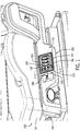
- a vehicle seat 100 includes a seat portion 102 located above and supported by a base portion 104.
- the seat portion 102 is generally L-shaped and is generally configured to support a user, e.g., a driver, in a seated position within a vehicle cab.
- a valve assembly 106 including a valve-control assembly 108, resides within the base portion 104 of the vehicle seat 100 below the seat portion 102.
- the base portion 104 also includes a cover structure 110 arranged to at least partly cover a pneumatic control valve 112 (partially shown in FIG. 4 ).
- the cover structure 110 extends at least partially along the seat portion 102 and accordingly can cover features of the seat 100 other than the control valve 112 (e.g., other components of the valve assembly 106).
- the cover structure 110 includes a cover panel 114 and a switch panel 116.
- a switch panel may be fastened to a cover panel using a variety of known fastening techniques, including snap-fit arrangements, adhesives, fasteners, and so on.
- the switch panel 116 is configured to nest within the cover panel 114, such that the switch panel 116 snaps into place within the cover panel 114 during installation.
- the cover panel 114 has an external surface 118 visible from outside the vehicle seat 100, an internal surface 120 (see FIG. 4 ) opposite the external surface 118.
- the switch panel 116 has an outer surface 122 visible from outside the vehicle seat 100 and an inner surface 124 (see FIG. 4 ) opposite the outer surface 122.
- the valve-control assembly 108 further includes a control button 130, illustrated as a control switch, that is configured to operate the pneumatic control valve 112 (see FIG. 4 ).
- the pneumatic control valve 112 is configured to raise or lower the vehicle seat 100 using pneumatics, i.e., compressed gases, although control of other functions may be possible in other embodiments.
- the pneumatic control valve 112 may control flow of compressed gases in order to perform a raising or lowering function, to adjust a height of the seat between an elevated (e.g., driving) position and a minimum (e.g., fully lowered) position.
- other control buttons can be included, such as control buttons 132 formed as additional control switches, as may be useful to control other seat-adjustment functions.
- a cover structure may sometimes be arranged to at least partly surround or otherwise cover one or more control switches or other control buttons.
- the switch panel 116 substantially surrounds the control buttons 130, 132.
- the switch panel 116 is generally rectangular, other switch panels can be squared, circular, or any other shape suited to at least partly surround relevant control buttons.
- the control buttons 130, 132 extend beyond the outer surface 122 of the switch panel 116 as may help to facilitate manual actuation. In some cases, however, the outer surface 122 of the switch panel 116 may be flush (i.e., even) with one or more of the control buttons 130, 132 or otherwise configured.
- a cover structure can be secured to a seat in different ways, such as with a variety of well-known fasteners.
- a cover structure can be configured to be attached to a vehicle seat by means of fasteners that can be engaged or disengaged without the direct use of tools.
- the cover structure 110 can be secured to the base portion 108 of the vehicle seat 100 using snap-in or other tool-less fasteners, such as snap-fit pegs or automatically-engaged clasps (not shown) that are provided on the internal surface 120 of the cover panel 114 (see FIG. 4 ).
- Control buttons according to embodiments of the disclosure can be configured in a variety of ways in order to provide appropriate functionality and accommodate a relevant catch, as discussed above.
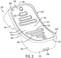
- the control button 130 is configured as a rocker switch.
- the rocker switch 130 is generally rectangular, having a midpoint 134, a top edge 138, a bottom edge 140, a first side edge 142 and a second side edge 144.
- the rocker switch 130 has a first side 146 and second side 148, both of which are partially partitioned by a medial cut 150.
- the medial cut 150 interrupts the first side 146 and second side 148 near the midpoint 134 of the rocker switch.
- other configurations are possible, including rocker or other switches with non-rectangular, non-symmetrical, or other geometries.
- the medial cut 150 is generally crescent-shaped to permit movement of the switch 130 relative to a pivot 152 (see FIG. 4 ).
- the rocker switch 130 can be pivotally rotated, i.e., rocked, about the pivot 152 to operate the pneumatic control valve 112 (see also FIGS. 4 and 5 ).
- buttons in other embodiments can be differently configured and actuated.
- the rocker switch 130 includes a front face 154 having indicia 156 disposed thereon.
- the indicia 156 are configured to correspond to, and provide different tactile engagement with, a top portion 158 and a bottom portion 160 of the rocker switch 130.
- the top portion 158 of the front face 154 includes at least one rib 162 and the bottom portion 160 of the front face 154 includes at least one cavity 164. Accordingly, a user who is manually actuating the rocker switch 130 can generally feel the difference between the at least one rib 162 and the at least one cavity 164 and thereby manually determine which portion of the front face 154 is being actuated.
- indicia may sometimes correspond to different lateral sides of a button, such as a switch configured to be laterally moved to adjust a seat, or may exhibit different forms than are illustrated in FIG. 2 .
- the front face 154 is concave along its length, so that the top portion 158 and the bottom portion 160 are generally coplanar near the midpoint 134 and curve upward toward the respective top edge 138 and bottom edge 140.
- the front face 154 can be planar, or convex, or even irregularly shaped.
- similar configurations may be provided on other control buttons or switches (e.g., the control buttons 132) to control other seat adjustment functions.
- a circular or other button may be used to adjust the height of the vehicle seat 100. Still further, the actions described in connection with the rocker switch 130 may be used to perform additional or alternative seat adjustment functions, other than height adjustment.
- the rocker switch 130 may be configured to control other seat adjustments, or another button (e.g., configured similarly to the buttons 132 as shown in FIG. 1 ) may be configured to control seat height.
- a control switch such as the rocker switch 130 may be particularly suited to include a catch in order to allow the control switch to be automatically retained in a particular orientation.
- a first catch 166 configured as a triangular tab or detent with a generally flat engagement face is formed on a bottom end 168 of the rocker switch 130.
- the first catch 166 is positioned on the bottom end 168 below the bottom edge 140 and between the first side 146 and the second side 148.
- the first catch 166 extends laterally away from the bottom end 168 as a solid, fixed tab.
- the first catch 166 may be integrally formed with the rocker switch 130.
- the first catch 166 (or another catch according to embodiments of the disclosure) may be formed as a hook, an extended lip, a recess, or otherwise.
- a catch may be formed separately from the rocker switch 130 and then affixed to the bottom end 168 thereof.
- a catch may be disposed elsewhere on the rocker switch 130, such as on the front face 154 or on one of the first or second sides 146, 148 of the rocker switch 130.
- multiple catches can be provided on the rocker switch 130, on one or more of its surfaces.
- a catch may be manually (or otherwise) adjustable, such as being configured to be extendable or retractable by a user.
- a second catch as may correspond to a first catch on a control button, can be provided on a cover structure or other part (e.g., base portion) of a seat.
- a second catch can be provided on a switch panel that is designed to at least partly surround the relevant control button.
- the switch panel 116 is generally rectangular and includes a perimeter edge 180 surrounding an intermediate surface 182 and a hole 184.
- the perimeter edge 180 includes a pocket 186, and a backing member 188 that extends in parallel with a top member 190.
- the walls of the pocket 186 can be configured to engaged (e.g., with a snap-fit) features on the cover panel 114 to help secure the switch panel 116 thereto.
- the perimeter edge 180 further includes a bottom member 192 and two side members 194, 196 that connect the top member 190 to the bottom member 192.
- the intermediate surface 182 is formed with inner walls 198 extending generally perpendicularly away from the intermediate surface 182 to surround the control switches 130, 132, as illustrated in FIG. 3 .
- the hole 184 is defined by an internal edge 200 of a generally planar pane 202, which also abuts the inner walls 198 of the intermediate surface 182.
- the inner walls 198 have an exterior 204 with a lip 206 (see FIGS. 4 and 5 ) that extends generally perpendicularly away from the exterior 204, below the perimeter edge 180.
- the switch panel 116 can be secured to the cover panel 114 by pressing the cover panel 114 against the perimeter edge 180 and above the lip 206, such that the switch panel 116 nests within the cover panel 114. In this manner, the switch panel 116 can snap into place within the cover panel 114 so that the cover and switch panels 114, 116 can be manipulated as a single component.
- a second catch can usefully be provided on the switch panel 114 although, as also noted above, other configurations are possible.
- a second catch 208 extends away from the inner walls 198 generally toward the hole 184.
- the second catch 208 is positioned between, and at a predetermined spacing from, the pane 202 and the intermediate surface 182. Accordingly, as also described below, the catch 208 can engage the first catch 166 (see FIG. 2 ) upon actuation of the rocker switch 130 to temporarily hold the rocker switch 130 in a particular orientation.
- a catch such as the second catch 208 can be formed on a variety of structures in a variety of ways.
- the second catch 208 is integrally formed as part of the switch panel 116 as a solid, fixed triangular tab or detent with a generally flat engagement face.
- a catch may be integrally formed as part of the cover panel 114 or another structure of the base portion 104 of the seat 100.
- the second catch 208 may be separately formed and then attached to the cover panel 114, the switch panel 116, or another structure.
- the second catch 208 (like the first catch 166) may be formed with rectangular, triangular, trapezoidal, or any number of other shapes or may be configured as a hook, an extended lip, a recess, and so on.
- a catch can be disposed elsewhere on the switch panel 116, such as on the pane 202, as may dispose the catch to appropriately engage a particular catch on the rocker switch 130 or other control button.
- multiple catches can be provided on the switch panel 116 or other component of a seat base, including on one or more surfaces thereof.
- different catches on a seat base can be configured to engage different catches on a control button, or to engage the same catch on a control button to hold the control button at particular positions.
- the second catch 208 or other corresponding feature can be manually (or otherwise) adjustable, such as being configured to be extendable or retractable by a user.
- a second catch can be disposed elsewhere on the cover structure 110, such as on the cover panel 114.
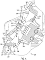
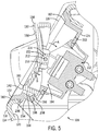
- FIGS. 4 and 5 illustrate aspects of the interoperation of the catches 166 and 208 to secure the rocker switch 130 in an engaged position.
- the rocker switch 130 With the valve-control assembly 108 appropriately assembled, the rocker switch 130 is positioned within the switch panel 116 between the inner walls 198 and apart from the hole 184.
- the pneumatic control valve 112 is positioned within the hole 184 and can, in some embodiments, be thereby secured to the switch panel 116.
- the rocker switch 130 is connected to the pneumatic control valve 112 at the pivot 152, which includes at least one pivot pin 212 inserted between a first arm 214 and a second arm 216 of the rocker switch.
- the rocker switch 130 can selectively actuate the pneumatic control valve 112 (e.g., cause the valve 112 to open or close), thereby controlling movement of compressed gases into or out of the seat (e.g., relative to a compressible gas reservoir for the seat).
- the rocker switch 130 can selectively actuate the rocker switch 130 by pressing down on the top portion 158 or the bottom portion 160 of the front face 154, such that the rocker switch 130 rotates about the pivot 152 to open or close the pneumatic control valve 112, respectively.
- the rocker switch 130 may rotate in a first direction (indicated by arrow A) or a second direction (indicated by arrow B) in order to operate the pneumatic control valve 112 to raise or lower the vehicle seat 100, respectively.
- arrow A first direction
- arrow B second direction
- the rocker switch 130 or other control buttons can be configured to be otherwise actuated to control any variety of other seat adjustments.
- the bottom end 168 of the rocker switch 130 is located circumferential alignment with the second catch 208 of the inner walls 198 relative to the rotational path of the rocker switch 130.
- the first catch 166 travels in the second direction toward the second catch 208.
- the first catch 166 may be rotated in the second direction beyond the second catch 208, causing the first catch 166 to become secured underneath the second catch 208.
- the rocker switch 130 can be secured against rotation in the first direction by forces exerted between the first and second catches 166, 208.
- the first catch 166 is configured to engage the second catch 208 when the rocker switch 130 is actuated by a predetermined amount, to secure the rocker switch 130 against movement. Accordingly, the second catch 208 can engage the first catch 166 to secure the pneumatic control valve 112 in a particular configuration.
- movement of the rocker switch 130 in the second direction causes the control valve 112 to open, which in turn causes the vehicle seat 100 to be lowered.
- engagement of the first and second catches 166, 208 can cause the pneumatic control valve 112 to be temporarily held open, such that the vehicle seat 100 automatically lowers to a particular level (e.g., to a fully lowered position) without continuous engagement of the rocker switch 130 by a user.
- the rocker switch 130 is also configured to be manually actuated to disengage the first catch 166 from the second catch 208.
- a user can press on the top portion 158 of the front face 154 of the rocker switch 130 to cause rotation in the first direction about the pivot 152.
- the rocker switch 130 can rotate in the first direction, whether to merely stop the lowering of the vehicle seat 100 or to further operate the pneumatic control valve 112 to raise the vehicle seat 100.
- the angled portion of the triangular tabs that form each of the catches 166, 208 are configured to contact the generally planar engagement surfaces of the other of the catches 208, 166 as the rocker switch 130 is moved in either of the first or second directions. This contact can help to induce appropriate elastic deformation of one or both of the rocker switch 130 (e.g., at the bottom end 168) or the switch panel (e.g., at the inner wall 198) to allow the catch 166 to move past the catch 208 without excessive resistance. In other embodiments, however, other configurations are possible.
- buttons e.g., other switches
- a different button may be used to adjust the height of the vehicle seat 100.
- the actions described in connection with the rocker switch 130 may be used to perform additional or alternative seat adjustment functions.
- multiple seat adjustment functions may be performed simultaneously, iteratively, automatically, or otherwise, including through operation or a single or multiple control buttons.
- a different point (or points) of engagement can be provided for corresponding catches on a control button and a vehicle seat.
- the predetermined amount of actuation that is require to engage the catches 166, 208 is determined in part by the locations of the second catch 208 on the inner wall 198 of the switch panel 116 and of the first catch 166 on the bottom end 168 of the rocker switch 130.
- different locations or other configurations can allow catches to engage each other after different predetermined amounts of movement of a relevant button.
- aspects of a cover structure can facilitate relatively easy access to components of the vehicle seat 100.
- the cover structure 110 is configured to be manually removable from outside the vehicle seat 100, such as through the use of a simple hand tool. Accordingly, users can readily remove the cover structure 110 in order to access the pneumatic control valve 112 or other components included in the base portion 104.
- a notch 220 extends laterally along a top edge 222 of the cover panel 114 and is configured to receive part of a hand tool, such as a screwdriver head.
- the cover panel 114 may be fastened to the vehicle seat 100 by snap-in fasteners, such as snap-fit pegs or clasps, or other known fasteners that can be operated without requiring direct engagement by tools. Accordingly, for example, with a hand tool positioned within the notch 220 to provide suitable leverage, the cover panel 114 can be relatively easily pried off of the vehicle seat 100.
- prying action from such a hand tool can cause snap-in fasteners (not shown) to be removed from corresponding receptacles on the cover panel 114 or the base portion 108 of vehicle seat 100, thereby allowing the cover panel 114 to be detached.
- the cover panel 114 can be thus detached with a generally pivoting movement, as partially illustrated in FIG. 6 .
- a cover structure (e.g., the cover panel 114) can be secured using threaded fasteners or other similar devices in addition, or as an alternative, to snap-in fasteners.
- removing the cover structure may include a combination of manual or other direct unfastening of certain fasteners in combination with a prying of the cover structure away from a seat via engagement of a tool with a notch (e.g., the notch 220).
- the cover panel 114 may facilitate useful access to the pneumatic control valve 112 or other components of the control valve assembly 106.
- the switch panel 116 can remain secured to the cover panel 114 during removal of the cover panel 114. Accordingly, the cover panel 114 and the switch panel 116 may be removed together. In some embodiments, the switch panel 116 can be removed separately from the cover panel 114, such as by first removing the switch panel 116 from the cover panel 114 then, as appropriate, using the notch 220 to remove the cover panel 114 from the vehicle seat 100.
- the notch 220 of the cover panel 114 is integrally formed with the cover panel 114 as a crescent-shaped notch, as may allow for appropriate access with a relevant hand tool while not creating excessively large openings in the cover panel 114 as a whole.
- other geometries or constructions are possible.
- embodiments of the disclosed support and support system can provide various benefits compared to conventional vehicle seats.
- appropriately configured notches on cover structures can allow improved access to control valves and other components, for maintenance or other activities.
- sets of catches on control buttons (e.g., switches) and other seat components (e.g., cover structures) can be configured to interoperate to secure a valve control in a particular configuration. This may be useful, for example, to cause a seat to automatically lower to a particular position without continuous engagement of a control button by a user.
- users can more quickly and efficiently enter and exit the vehicle seats, which can lead to greater comfort and ease of use.
Landscapes
- Engineering & Computer Science (AREA)
- Aviation & Aerospace Engineering (AREA)
- Transportation (AREA)
- Mechanical Engineering (AREA)
- Human Computer Interaction (AREA)
- Physics & Mathematics (AREA)
- General Physics & Mathematics (AREA)
- Automation & Control Theory (AREA)
- Seats For Vehicles (AREA)
- Actuator (AREA)
Abstract
Description
- In commercial and other vehicles, seats (e.g., driver seats) can be adjusted using seat adjustment devices. For example, the height of a driver seat may be adjusted by a control assembly utilizing pneumatic systems.
- In some control assemblies for seat adjustments, a user can control valves and actuators through a control panel that contains switches or other buttons. Each of the switches or buttons can be designed to control at least one adjustment function, although some switches can have more than one function.
- In one aspect, a valve-control assembly for a vehicle seat can include a pneumatic control valve configured to control at least one seat adjustment function. A control button can be configured to operate the pneumatic control valve, and a cover structure can be arranged to one or more of at least partly cover the pneumatic control valve or at least partly surround the control button. The control button can include a first tab, and the cover structure can include a second tab. The first tab can be configured to engage the second tab, when the control button is actuated by a predetermined amount, to secure the control button against movement and thereby secure the pneumatic control valve in an actuated (e.g., open) configuration.
- The valve-control assembly can include at least one seat adjustment function controlled by the pneumatic control valve, such as a height adjustment for the vehicle seat. The valve-control assembly can lower the vehicle seat when the pneumatic control valve is in the actuated configuration. The control switch can be configured to be manually engaged to disengage the first tab from the second tab.
- The control button can be configured to be manually moved in a first direction to disengage the first tab from the second tab. The control button can be further configured to control the pneumatic control valve to raise a height of the vehicle seat via movement of the control button in the first direction.
- The cover structure can include a notch that is configured to receive a hand tool, from outside the vehicle seat, to remove the cover structure from the valve-control assembly. The cover structure can include a cover panel and a switch panel. The switch panel can include the second tab and be secured to the cover panel to at least partly surround the control switch. The pneumatic control valve can be secured to the switch panel.
- In some embodiments, the control button can be a rocker switch, and the first tab can be formed on a bottom end of the rocker switch. The control button can be included in a plurality of manual controls for a plurality of seat adjustment functions.
- In another aspect, a valve-control assembly can be provided for a vehicle seat with a control valve that is configured to control at least one seat adjustment function. The valve-control assembly can include a control switch configured to be manually actuated to operate the control valve, and a cover structure arranged to one or more of at least partly cover the control valve or at least partly surround the control switch. The control switch can include a switch body and a first catch integrally formed with the switch body. The cover structure can include a switch panel and a second catch integrally formed with the switch panel. The first catch can be configured to engage the second catch, when the control switch is actuated by a predetermined amount, to secure the control switch against movement and thereby secure the control valve in a first configuration.
- The first catch can be formed as a first solid tab and the second catch is formed as a second solid tab. The cover structure can further include a cover panel and the switch panel is configured to nest within part of the cover panel. The switch panel is configured to at least partly surround a plurality of manual controls for a plurality of seat adjustment functions. The control switch can be configured to control a height adjustment of the vehicle seat and the first catch can be configured to engage the second catch when the control switch is actuated to fully lower the vehicle seat. The cover panel can include a notch that is configured to receive a hand tool, from outside the vehicle seat, to remove the cover structure from the valve-control assembly and thereby provide access to the control valve.
- In still another aspect, a vehicle seat can have a seat portion, a base portion that supports the seat portion, and a valve assembly included in the base portion, including a first pneumatic control valve. The vehicle seat can further include a control switch included in the base portion, the control switch including a first catch and being configured to operate the first pneumatic control valve to raise or lower the seat portion. A second catch can be included on the base portion. The first catch can be configured to engage the second catch, when the control switch is actuated by a predetermined amount, to secure the control switch against movement and thereby secure the first pneumatic control valve to fully lower the seat portion.
- The base portion can further include a cover structure. The second catch can be integrally formed as part of the cover structure. The first catch can be integrally formed as part of the control switch. The cover structure can include a notch that is configured to receive a hand tool, from outside the vehicle seat, to remove the cover structure from the base portion and thereby provide access to the valve assembly.
- Features which are described in the context of separate aspects and/or embodiments of the invention may be used together and/or be interchangeable wherever possible. Similarly, where features are, for brevity, described in the context of a single embodiment, those features may also be provided separately or in any suitable sub-combination. Features described in connection with the assembly or seat may have corresponding features definable and/or combinable with respect to each other and/or a method or vice versa, and these embodiments are specifically envisaged.
- The accompanying drawings, which are incorporated in and form a part of this specification, illustrate embodiments of the disclosure and, together with the description, serve to explain the principles of embodiments of the disclosure:
-
FIG. 1 is an isometric partial view of a vehicle seat, including a valve-control assembly for the vehicle seat according to some embodiments of the disclosure; -
FIG. 2 is an isometric bottom, front, left side view of a control switch for the valve-control assembly ofFIG. 1 ; -
FIG. 3 is an isometric front, top, left side view of a panel for the valve-control assembly ofFIG. 1 ; -
FIG. 4 is a sectional partial view of the valve-control assembly ofFIG. 1 in a disengaged state, taken along the lines 4-4 ofFIG. 1 ; -
FIG. 5 is a sectional partial view of the valve-control assembly ofFIG. 1 in an engaged state, taken along the lines 4-4 ofFIG. 1 ; and -
FIG. 6 is an isometric partial view of the valve-control assembly ofFIG. 1 in a partially disassembled state. - Before any embodiments of the disclosure are explained in detail, it is to be understood that the disclosure is not limited in its application to the details of construction and the arrangement of components set forth in the following description or illustrated in the following drawings. The disclosure is capable of other embodiments and of being practiced or of being carried out in various ways. Also, it is to be understood that the phraseology and terminology used herein is for the purpose of description and should not be regarded as limiting. The use of "including," "comprising," or "having" and variations thereof herein is meant to encompass the items listed thereafter and equivalents thereof as well as additional items.
- Likewise, unless otherwise specified or limited, the terms "mounted," "connected," "supported," and "coupled" and variations thereof are used broadly and encompass both direct and indirect mountings, connections, supports, and couplings. Further, unless otherwise specified or limited, "connected" and "coupled" are not restricted to physical or mechanical connections or couplings.
- As used herein, unless otherwise defined or limited, directional references such as "top," "bottom," "left," "right," "front," "back," and so on are used as examples only, relative to the particular reference frame or figure associated with the relevant discussion. For example, a feature described as being located on a "top" portion of a body relative to a particular figure or example may not necessarily be located on a top portion of the body, relative to gravity or other features, in every installation or configuration.
- The following discussion is presented to enable a person skilled in the art to make and use embodiments of the disclosure. Various modifications to the illustrated embodiments will be readily apparent to those skilled in the art, and the generic principles herein can be applied to other embodiments and applications without departing from embodiments of the disclosure. Thus, embodiments of the disclosure are not intended to be limited to embodiments shown, but are to be accorded the widest scope consistent with the principles and features disclosed herein. The following detailed description is to be read with reference to the figures, in which like elements in different figures have like reference numerals. The figures, which are not necessarily to scale, depict selected embodiments and are not intended to limit the scope of embodiments of the disclosure. Skilled artisans will recognize the examples provided herein have many useful alternatives and fall within the scope of embodiments of the disclosure.
- Some figures may include multiple instances of similar structures or structural relationships. For convenience of presentation, in select figures, only some of these similar structures or relationships may be specifically labeled with a reference number. One of skill in the art will recognize that the features not labeled with reference numbers can include similar aspects and perform similar functions to similar features that are labeled with reference numbers.
- In some cases, it may be useful to adjust seats to permit easy entry into and exit from a vehicle cab, among other activities. In this regard, for example, it may be helpful for some drivers to adjust seat height when the drivers enter and exit the cab. For example, movement into and out of a seat may be relatively easy if a driver is able to adjust a seat from an elevated (e.g., driving) position to a lowered (e.g., minimum height) position. This may be particularly useful, for example, for elevated or space-constrained cabs.
- Some vehicle seats can be configured to allow a user to adjust the height of the vehicle seat between an elevated-height position and a minimum-height position by manually engaging a control button, such as a rocker switch. This can allow for highly customized adjustment of the vehicle seat. However, conventional arrangements may require a user to continually interact with a control-assembly to effect ongoing adjustment of a seat. Accordingly, it may be useful to provide improvements that allow a user to quickly and efficiently move the vehicle seat to a minimum-height (or other) position, including without continual manual engagement of a control device, such as a control button. For example, it may assist users in exiting or entering the vehicle cab if the seat can be moved to - and held in - a minimum-height position without ongoing action by the users.
- Embodiments of the present disclosure can provide a valve-control assembly that can beneficially address these and other aspects of vehicle seat adjustment. Further, some embodiments can provide a valve-control assembly that is substantially more durable and simpler to manufacture, install, and operate than conventional auto-adjust assemblies, such as those that allow users to pre-set particular seating configurations.
- Generally, a valve-control assembly for a vehicle seat according to this disclosure can include a control button with a catch that can hold the control button in an actuated position. Usefully, this arrangement can help to cause a seat to move to a particular position without ongoing manual engagement of the button by a user. For example, in some embodiments, a valve-control assembly can be configured so that a user can move a seat to a particular configuration by actuating a rocker switch (or other button) with a discrete and limited motion such as a one-time, single finger-press (and release), rather than with a protracted actuation such as continuously holding down the rocker switch (or other button). For example, upon such an discrete, manual actuation a catch on the rocker switch (or other button) can engage a catch on a separate structure in order to hold the rocker switch (or other button) in an actuated position and thereby hold an associated valve assembly for seat adjustment in a particular configuration (e.g., with a valve in an open orientation). In some configurations, accordingly, a user can use a quick, single action to cause a seat to move to a minimum-height position and thereby allow entrance into and egress from the cab with maximal ease.
- In some embodiments, to provide this functionality, a rocker switch or other button for a vehicle seat can include a first mechanical catch (e.g., on a bottom end of the switch) that engages a second mechanical catch on a cover structure or other feature of the seat. Once mechanically engaged with the first catch, the second catch can retain the rocker switch or other button in a secured position, such as may temporarily prevent the rocker switch or other button from rotating or otherwise moving (e.g., returning to a "home" location). Thus, the first catch and the second catch, rather than the user, can retain the rocker switch in the secured position. Further, in some cases, the secured position can correspond to an actuated position, such as a position in which the rocker switch or other button actuates a pneumatic control valve to lower the vehicle seat from an elevated position to a minimum position. Accordingly, in some cases, the engagement of the first and second catches can cause a valve to be held in an actuated (e.g., open) position so that the relevant seat is automatically moved to a lowered position.
- Relatedly, in some conventional arrangements, it may be difficult to access components of a valve assembly, including a valve-control assembly, for maintenance or other tasks. Accordingly, some embodiments of the disclosure can include a valve-control assembly with a cover structure (e.g., a cover panel and attached switch panel) that is capable of being quickly removed by a hand tool, from outside the vehicle seat. For example, some cover structures according to the disclosure can include a notch along a top (or other) edge that can provide a space for insertion of the head of a hand tool, such as a screwdriver, to help pry the cover structure away from other structures of the vehicle seat. In this way, for example, the cover structure can be quickly and easily removed to allow access for maintenance of a valve-control assembly, a control valve assembly, or other components. For example, in some arrangements, with the cover structure removed, a user can readily access a bank of pneumatic control valves that were previously enclosed by the cover structure.
- In some embodiments, a cover structure can include a cover panel and a smaller switch panel that is secured to (e.g. nested with) the cover panel to surround control switches or other buttons of a valve-control assembly. In such a case, for example, the switch panel may be removed from the cover panel for more limited access to control valves or valve controls, thereby retaining the cover panel in its secured positon. Further, in some cases, such a switch panel can also include a catch for engaging a control button, such as described above.
- As one example, referring to
FIG. 1 , avehicle seat 100 includes aseat portion 102 located above and supported by abase portion 104. Theseat portion 102 is generally L-shaped and is generally configured to support a user, e.g., a driver, in a seated position within a vehicle cab. Avalve assembly 106, including a valve-control assembly 108, resides within thebase portion 104 of thevehicle seat 100 below theseat portion 102. - The
base portion 104 also includes acover structure 110 arranged to at least partly cover a pneumatic control valve 112 (partially shown inFIG. 4 ). Thecover structure 110 extends at least partially along theseat portion 102 and accordingly can cover features of theseat 100 other than the control valve 112 (e.g., other components of the valve assembly 106). - Still referring to
FIG. 1 , thecover structure 110 includes acover panel 114 and aswitch panel 116. Generally, a switch panel may be fastened to a cover panel using a variety of known fastening techniques, including snap-fit arrangements, adhesives, fasteners, and so on. For example, as also discussed below, theswitch panel 116 is configured to nest within thecover panel 114, such that theswitch panel 116 snaps into place within thecover panel 114 during installation. Thecover panel 114 has anexternal surface 118 visible from outside thevehicle seat 100, an internal surface 120 (seeFIG. 4 ) opposite theexternal surface 118. Similarly, theswitch panel 116 has anouter surface 122 visible from outside thevehicle seat 100 and an inner surface 124 (seeFIG. 4 ) opposite theouter surface 122. - With continued reference to
FIG. 1 , the valve-control assembly 108 further includes acontrol button 130, illustrated as a control switch, that is configured to operate the pneumatic control valve 112 (seeFIG. 4 ). In the embodiment illustrated, thepneumatic control valve 112 is configured to raise or lower thevehicle seat 100 using pneumatics, i.e., compressed gases, although control of other functions may be possible in other embodiments. When actuated, for example, thepneumatic control valve 112 may control flow of compressed gases in order to perform a raising or lowering function, to adjust a height of the seat between an elevated (e.g., driving) position and a minimum (e.g., fully lowered) position. In some embodiments, other control buttons can be included, such ascontrol buttons 132 formed as additional control switches, as may be useful to control other seat-adjustment functions. - For protective, aesthetic, or other reasons, a cover structure may sometimes be arranged to at least partly surround or otherwise cover one or more control switches or other control buttons. For example, in the illustrated embodiment, the
switch panel 116 substantially surrounds thecontrol buttons switch panel 116 is generally rectangular, other switch panels can be squared, circular, or any other shape suited to at least partly surround relevant control buttons. As illustrated inFIG. 1 , thecontrol buttons outer surface 122 of theswitch panel 116 as may help to facilitate manual actuation. In some cases, however, theouter surface 122 of theswitch panel 116 may be flush (i.e., even) with one or more of thecontrol buttons - In different embodiments, a cover structure can be secured to a seat in different ways, such as with a variety of well-known fasteners. In some embodiments, a cover structure can be configured to be attached to a vehicle seat by means of fasteners that can be engaged or disengaged without the direct use of tools. For example, the
cover structure 110 can be secured to thebase portion 108 of thevehicle seat 100 using snap-in or other tool-less fasteners, such as snap-fit pegs or automatically-engaged clasps (not shown) that are provided on theinternal surface 120 of the cover panel 114 (seeFIG. 4 ). - Control buttons according to embodiments of the disclosure, including the
control button 130, can be configured in a variety of ways in order to provide appropriate functionality and accommodate a relevant catch, as discussed above. For example, as illustrated inFIG. 2 in particular, thecontrol button 130 is configured as a rocker switch. Therocker switch 130 is generally rectangular, having amidpoint 134, atop edge 138, abottom edge 140, afirst side edge 142 and asecond side edge 144. Therocker switch 130 has afirst side 146 andsecond side 148, both of which are partially partitioned by amedial cut 150. Themedial cut 150 interrupts thefirst side 146 andsecond side 148 near themidpoint 134 of the rocker switch. In other embodiments, however, other configurations are possible, including rocker or other switches with non-rectangular, non-symmetrical, or other geometries. - Still referring to
FIG. 2 , themedial cut 150 is generally crescent-shaped to permit movement of theswitch 130 relative to a pivot 152 (seeFIG. 4 ). Thus, for example, therocker switch 130 can be pivotally rotated, i.e., rocked, about thepivot 152 to operate the pneumatic control valve 112 (see alsoFIGS. 4 and5 ). As also alluded to above, however, buttons in other embodiments can be differently configured and actuated. - To assist in user engagement, in the embodiment illustrated, the
rocker switch 130 includes afront face 154 havingindicia 156 disposed thereon. In the illustrated embodiment, theindicia 156 are configured to correspond to, and provide different tactile engagement with, atop portion 158 and abottom portion 160 of therocker switch 130. For example, thetop portion 158 of thefront face 154 includes at least onerib 162 and thebottom portion 160 of thefront face 154 includes at least onecavity 164. Accordingly, a user who is manually actuating therocker switch 130 can generally feel the difference between the at least onerib 162 and the at least onecavity 164 and thereby manually determine which portion of thefront face 154 is being actuated. - In other embodiments, other configurations are possible. For example, indicia may sometimes correspond to different lateral sides of a button, such as a switch configured to be laterally moved to adjust a seat, or may exhibit different forms than are illustrated in
FIG. 2 . - With continued reference to
FIG. 2 , thefront face 154 is concave along its length, so that thetop portion 158 and thebottom portion 160 are generally coplanar near themidpoint 134 and curve upward toward the respectivetop edge 138 andbottom edge 140. Optionally, thefront face 154 can be planar, or convex, or even irregularly shaped. In addition, similar configurations may be provided on other control buttons or switches (e.g., the control buttons 132) to control other seat adjustment functions. - In some embodiments, a circular or other button, rather than or in addition to the
rocker switch 130, may be used to adjust the height of thevehicle seat 100. Still further, the actions described in connection with therocker switch 130 may be used to perform additional or alternative seat adjustment functions, other than height adjustment. For example, therocker switch 130 may be configured to control other seat adjustments, or another button (e.g., configured similarly to thebuttons 132 as shown inFIG. 1 ) may be configured to control seat height. - In some embodiments, a control switch such as the
rocker switch 130 may be particularly suited to include a catch in order to allow the control switch to be automatically retained in a particular orientation. As depicted inFIG. 2 , for example, afirst catch 166 configured as a triangular tab or detent with a generally flat engagement face is formed on abottom end 168 of therocker switch 130. Thefirst catch 166 is positioned on thebottom end 168 below thebottom edge 140 and between thefirst side 146 and thesecond side 148. Thefirst catch 166 extends laterally away from thebottom end 168 as a solid, fixed tab. As such, thefirst catch 166 may be integrally formed with therocker switch 130. - In other embodiments, other configurations are possible. For example, the first catch 166 (or another catch according to embodiments of the disclosure) may be formed as a hook, an extended lip, a recess, or otherwise. In some embodiments, a catch may be formed separately from the
rocker switch 130 and then affixed to thebottom end 168 thereof. In some embodiments, a catch may be disposed elsewhere on therocker switch 130, such as on thefront face 154 or on one of the first orsecond sides rocker switch 130. Optionally, multiple catches can be provided on therocker switch 130, on one or more of its surfaces. In some configurations, a catch may be manually (or otherwise) adjustable, such as being configured to be extendable or retractable by a user. - In different embodiments, a second catch, as may correspond to a first catch on a control button, can be provided on a cover structure or other part (e.g., base portion) of a seat. In some embodiments, a second catch can be provided on a switch panel that is designed to at least partly surround the relevant control button. Referring to
FIG. 3 , for example, theswitch panel 116 is generally rectangular and includes aperimeter edge 180 surrounding anintermediate surface 182 and ahole 184. Theperimeter edge 180 includes apocket 186, and abacking member 188 that extends in parallel with atop member 190. The walls of thepocket 186 can be configured to engaged (e.g., with a snap-fit) features on thecover panel 114 to help secure theswitch panel 116 thereto. - Still referring to
FIG. 3 , theperimeter edge 180 further includes abottom member 192 and twoside members top member 190 to thebottom member 192. Within theperimeter edge 180, theintermediate surface 182 is formed withinner walls 198 extending generally perpendicularly away from theintermediate surface 182 to surround the control switches 130, 132, as illustrated inFIG. 3 . Thehole 184 is defined by aninternal edge 200 of a generallyplanar pane 202, which also abuts theinner walls 198 of theintermediate surface 182. - As further illustrated in
FIGS. 4 and5 , theinner walls 198 have an exterior 204 with a lip 206 (seeFIGS. 4 and5 ) that extends generally perpendicularly away from the exterior 204, below theperimeter edge 180. Thus arranged, for example, theswitch panel 116 can be secured to thecover panel 114 by pressing thecover panel 114 against theperimeter edge 180 and above thelip 206, such that theswitch panel 116 nests within thecover panel 114. In this manner, theswitch panel 116 can snap into place within thecover panel 114 so that the cover and switchpanels - Due to its close proximity to the
rocker switch 130, a second catch can usefully be provided on theswitch panel 114 although, as also noted above, other configurations are possible. For example, referring again toFIG. 3 , asecond catch 208 extends away from theinner walls 198 generally toward thehole 184. Thesecond catch 208 is positioned between, and at a predetermined spacing from, thepane 202 and theintermediate surface 182. Accordingly, as also described below, thecatch 208 can engage the first catch 166 (seeFIG. 2 ) upon actuation of therocker switch 130 to temporarily hold therocker switch 130 in a particular orientation. - A catch such as the
second catch 208 can be formed on a variety of structures in a variety of ways. For example, as illustrated inFIG. 3 , thesecond catch 208 is integrally formed as part of theswitch panel 116 as a solid, fixed triangular tab or detent with a generally flat engagement face. In other embodiments, however, other configurations are possible. For example, a catch may be integrally formed as part of thecover panel 114 or another structure of thebase portion 104 of theseat 100. Similarly, thesecond catch 208 may be separately formed and then attached to thecover panel 114, theswitch panel 116, or another structure. Further, in different embodiments, the second catch 208 (like the first catch 166) may be formed with rectangular, triangular, trapezoidal, or any number of other shapes or may be configured as a hook, an extended lip, a recess, and so on. - In some embodiments, a catch can be disposed elsewhere on the
switch panel 116, such as on thepane 202, as may dispose the catch to appropriately engage a particular catch on therocker switch 130 or other control button. Optionally, multiple catches can be provided on theswitch panel 116 or other component of a seat base, including on one or more surfaces thereof. For example, different catches on a seat base can be configured to engage different catches on a control button, or to engage the same catch on a control button to hold the control button at particular positions. In some embodiments, thesecond catch 208 or other corresponding feature can be manually (or otherwise) adjustable, such as being configured to be extendable or retractable by a user. In some embodiments, a second catch can be disposed elsewhere on thecover structure 110, such as on thecover panel 114. -
FIGS. 4 and5 illustrate aspects of the interoperation of thecatches rocker switch 130 in an engaged position. With the valve-control assembly 108 appropriately assembled, therocker switch 130 is positioned within theswitch panel 116 between theinner walls 198 and apart from thehole 184. Thepneumatic control valve 112 is positioned within thehole 184 and can, in some embodiments, be thereby secured to theswitch panel 116. Further, therocker switch 130 is connected to thepneumatic control valve 112 at thepivot 152, which includes at least onepivot pin 212 inserted between afirst arm 214 and asecond arm 216 of the rocker switch. - Thus arranged, as the
rocker switch 130 rotates about thepivot 152, such as indicated by arrows A and B, therocker switch 130 can selectively actuate the pneumatic control valve 112 (e.g., cause thevalve 112 to open or close), thereby controlling movement of compressed gases into or out of the seat (e.g., relative to a compressible gas reservoir for the seat). For example, a user can actuate therocker switch 130 by pressing down on thetop portion 158 or thebottom portion 160 of thefront face 154, such that therocker switch 130 rotates about thepivot 152 to open or close thepneumatic control valve 112, respectively. In the illustrated embodiment, in particular, therocker switch 130 may rotate in a first direction (indicated by arrow A) or a second direction (indicated by arrow B) in order to operate thepneumatic control valve 112 to raise or lower thevehicle seat 100, respectively. In other embodiments, however, other configurations are possible. For example, therocker switch 130 or other control buttons can be configured to be otherwise actuated to control any variety of other seat adjustments. - As also illustrated in
FIGS. 4 and5 , thebottom end 168 of therocker switch 130, including thefirst catch 166, is located circumferential alignment with thesecond catch 208 of theinner walls 198 relative to the rotational path of therocker switch 130. As guided by thepivot 152, when therocker switch 130 is actuated by pressing on thebottom portion 160 of thefront face 154, thefirst catch 166 travels in the second direction toward thesecond catch 208. With sufficient rotation of therocker switch 130, as illustrated inFIG. 5 in particular, thefirst catch 166 may be rotated in the second direction beyond thesecond catch 208, causing thefirst catch 166 to become secured underneath thesecond catch 208. Thus, for example, via engagement of thefirst catch 166 with thesecond catch 208, therocker switch 130 can be secured against rotation in the first direction by forces exerted between the first andsecond catches - In this manner, the
first catch 166 is configured to engage thesecond catch 208 when therocker switch 130 is actuated by a predetermined amount, to secure therocker switch 130 against movement. Accordingly, thesecond catch 208 can engage thefirst catch 166 to secure thepneumatic control valve 112 in a particular configuration. In the embodiment illustrated, as also discussed above, movement of therocker switch 130 in the second direction causes thecontrol valve 112 to open, which in turn causes thevehicle seat 100 to be lowered. Thus, engagement of the first andsecond catches pneumatic control valve 112 to be temporarily held open, such that thevehicle seat 100 automatically lowers to a particular level (e.g., to a fully lowered position) without continuous engagement of therocker switch 130 by a user. - Still referring to
FIG. 5 , therocker switch 130 is also configured to be manually actuated to disengage thefirst catch 166 from thesecond catch 208. For example, with thecatches top portion 158 of thefront face 154 of therocker switch 130 to cause rotation in the first direction about thepivot 152. Once the user exerts sufficient force to overcome the engagement between thefirst catch 166 and thesecond catch 208, therocker switch 130 can rotate in the first direction, whether to merely stop the lowering of thevehicle seat 100 or to further operate thepneumatic control valve 112 to raise thevehicle seat 100. - In some embodiments, it may be useful to configure catches to appropriately balance secure engagement and relatively easy actuation by a user. For example, as illustrated in
FIGS. 4 and5 , the angled portion of the triangular tabs that form each of thecatches catches rocker switch 130 is moved in either of the first or second directions. This contact can help to induce appropriate elastic deformation of one or both of the rocker switch 130 (e.g., at the bottom end 168) or the switch panel (e.g., at the inner wall 198) to allow thecatch 166 to move past thecatch 208 without excessive resistance. In other embodiments, however, other configurations are possible. - In some embodiments, as also noted above, similar configurations and concepts may be implemented relative to other buttons (e.g., other switches) to control height adjustments or other seat-adjustment functions. For example, in some embodiments, a different button may be used to adjust the height of the
vehicle seat 100. Still further, the actions described in connection with therocker switch 130 may be used to perform additional or alternative seat adjustment functions. For example, in some embodiments, multiple seat adjustment functions may be performed simultaneously, iteratively, automatically, or otherwise, including through operation or a single or multiple control buttons. - As another example, in some embodiments, a different point (or points) of engagement can be provided for corresponding catches on a control button and a vehicle seat. For example, with reference to
FIGS. 4 and5 , the predetermined amount of actuation that is require to engage thecatches second catch 208 on theinner wall 198 of theswitch panel 116 and of thefirst catch 166 on thebottom end 168 of therocker switch 130. In other embodiments, different locations or other configurations can allow catches to engage each other after different predetermined amounts of movement of a relevant button. - In addition to convenient operational functionality for users, it may also be useful to improve vehicle seats relative to maintenance or other related activities. In some embodiments, for example, aspects of a cover structure can facilitate relatively easy access to components of the
vehicle seat 100. For example, to assist with maintenance or other tasks, thecover structure 110 is configured to be manually removable from outside thevehicle seat 100, such as through the use of a simple hand tool. Accordingly, users can readily remove thecover structure 110 in order to access thepneumatic control valve 112 or other components included in thebase portion 104. - Referring now to
FIG. 6 , in particular, the valve-control assembly 108 can be accessed relatively easily by removing thecover panel 114 from thebase portion 104 of thevehicle seat 100. In particular, anotch 220 extends laterally along atop edge 222 of thecover panel 114 and is configured to receive part of a hand tool, such as a screwdriver head. As mentioned above, thecover panel 114 may be fastened to thevehicle seat 100 by snap-in fasteners, such as snap-fit pegs or clasps, or other known fasteners that can be operated without requiring direct engagement by tools. Accordingly, for example, with a hand tool positioned within thenotch 220 to provide suitable leverage, thecover panel 114 can be relatively easily pried off of thevehicle seat 100. For example, prying action from such a hand tool can cause snap-in fasteners (not shown) to be removed from corresponding receptacles on thecover panel 114 or thebase portion 108 ofvehicle seat 100, thereby allowing thecover panel 114 to be detached. In some embodiments, thecover panel 114 can be thus detached with a generally pivoting movement, as partially illustrated inFIG. 6 . - In some embodiments, a cover structure (e.g., the cover panel 114) can be secured using threaded fasteners or other similar devices in addition, or as an alternative, to snap-in fasteners. In such a case, for example, removing the cover structure may include a combination of manual or other direct unfastening of certain fasteners in combination with a prying of the cover structure away from a seat via engagement of a tool with a notch (e.g., the notch 220).
- Generally, removal of the
cover panel 114 may facilitate useful access to thepneumatic control valve 112 or other components of thecontrol valve assembly 106. In some embodiments, theswitch panel 116 can remain secured to thecover panel 114 during removal of thecover panel 114. Accordingly, thecover panel 114 and theswitch panel 116 may be removed together. In some embodiments, theswitch panel 116 can be removed separately from thecover panel 114, such as by first removing theswitch panel 116 from thecover panel 114 then, as appropriate, using thenotch 220 to remove thecover panel 114 from thevehicle seat 100. - In different embodiments, different configurations for a cover structure and associated notch are possible. For example, the
notch 220 of thecover panel 114 is integrally formed with thecover panel 114 as a crescent-shaped notch, as may allow for appropriate access with a relevant hand tool while not creating excessively large openings in thecover panel 114 as a whole. In other embodiments, however, other geometries or constructions are possible. - Thus, embodiments of the disclosed support and support system can provide various benefits compared to conventional vehicle seats. For example, in some embodiments, appropriately configured notches on cover structures can allow improved access to control valves and other components, for maintenance or other activities. As another example, sets of catches on control buttons (e.g., switches) and other seat components (e.g., cover structures) can be configured to interoperate to secure a valve control in a particular configuration. This may be useful, for example, to cause a seat to automatically lower to a particular position without continuous engagement of a control button by a user. In this regard, for example, users can more quickly and efficiently enter and exit the vehicle seats, which can lead to greater comfort and ease of use.
- The previous description of the disclosed embodiments is provided to enable any person skilled in the art to make or use the disclosure. Various modifications to these embodiments will be readily apparent to those skilled in the art, and the generic principles defined herein may be applied to other embodiments without departing from the spirit or scope of the disclosure. Thus, the disclosure is not intended to be limited to the embodiments shown herein but is to be accorded the widest scope consistent with the principles and novel features disclosed herein.
- Features which are described in the context of separate embodiments may also be provided in combination in a single embodiment. Conversely, various features which are, for brevity, described in the context of a single embodiment, may also be provided separately or in any suitable sub-combination. The applicant hereby gives notice that new claims may be formulated to such features and/or combinations of such features during the prosecution of the present application or of any further application derived therefrom. Features of the assemblies and seats described may be incorporated into/used in corresponding methods and vice versa.
- For the sake of completeness, it is also stated that the term "comprising" does not exclude other elements or steps, the term "a" or "an" does not exclude a plurality, a single feature or unit may fulfil the functions of several means recited in the claims and any reference signs in the claims shall not be construed as limiting the scope of the claims.
Claims (15)
- A valve-control assembly (108) for a vehicle seat (100), the valve-control assembly comprising:a pneumatic control valve (112) configured to control at least one seat adjustment function;a control button (130) configured to operate the pneumatic control valve (112); anda cover structure (110) arranged to one or more of: at least partly cover the pneumatic control valve (112) or at least partly surround the control button (130);the control button (130) including a first catch (166); andthe cover structure (110) including a second catch (208);the first catch (166) being configured to engage the second catch (208), when the control button (130) is actuated by a predetermined amount in a first direction, to secure the control button (130) against movement in a second direction and thereby secure the pneumatic control valve (112) in an actuated configuration.
- The valve-control assembly of Claim 1, wherein the at least one seat adjustment function controlled by the pneumatic control valve (112) is a height adjustment for the vehicle seat (100).
- The valve-control assembly of Claim 2, wherein the pneumatic control valve (112) is configured to lower the vehicle seat (100) when the pneumatic control valve (112) is in the actuated configuration.
- The valve-control assembly of any of the preceding claims, wherein the control button (130) is configured to be manually engaged to disengage the first catch (166) from the second catch (208).
- The valve-control assembly of any of the preceding claims, wherein the control button (130) is a control switch that is configured to be manually moved in the second direction, opposite the first direction, to disengage the first catch (166) from the second catch (208); and
wherein the control switch is further configured to control the pneumatic control valve (112) to raise a height of the vehicle seat (100) via movement of the control switch in the second direction. - The valve-control assembly of Claim 5, wherein the control button (130) is a rocker switch, wherein the first direction is a first rotational direction, and optionally or preferably wherein the first catch (166) is formed on a bottom end of the rocker switch.
- The valve-control assembly of any of the preceding claims, wherein the first and second catches (166, 208) are mechanical catches that are configured to mechanically engage each other to secure the control button (130) against movement.
- The valve-control assembly of any of the preceding claims, wherein the cover structure (110) further includes a notch (220) that is configured to receive a hand tool, from outside the vehicle seat, to remove the cover structure (110) from the vehicle seat (100).
- The valve-control assembly of any of the preceding claims, wherein the cover structure (110) includes a cover panel (114) and a switch panel (116), the switch panel (116) including the second catch (208) and being secured to the cover panel (114) to at least partly surround the control button (130).
- The valve-control assembly of Claim 9, wherein the pneumatic control valve (112) is secured to the switch panel (116).
- The valve-control assembly of any of the preceding claims, wherein first catch (166) is integrally formed with the control button (130); and
wherein the second catch (208) is integrally formed with a switch panel (116) of the cover structure (110). - The valve-control assembly of claim 11, wherein the first catch (166) is a first triangular tab and the second catch (208) is a second triangular tab.
- The valve-control assembly of any of the preceding claims, wherein the control button (130) is included in a plurality of manual controls (132) for a plurality of seat adjustment functions, each of the manual controls of the plurality of manual controls (132) being secured to the cover structure (110).
- The valve-control assembly of claim 12, wherein the plurality of manual controls (132) are disposed within a pocket (186) in a switch panel (116), the pocket (186) being surrounded by a perimeter edge (180) of the switch panel (116) and including hole (184) that is surrounded by inner walls (198) of an intermediate surface (182) of the switch panel, the control button (130) being disposed within the hole (184), and optionally or preferably wherein the second catch (208) is integrally formed on one of the inner walls (198).
- A vehicle seat (100) comprising:a seat portion (102);a base portion (104) that supports the seat portion (102);wherein the valve-control assembly (108) of any of the preceding claims is included in the base portion (104) to control a height adjustment of the seat portion (102).
Applications Claiming Priority (1)
| Application Number | Priority Date | Filing Date | Title |
|---|---|---|---|
| US16/365,077 US10682927B1 (en) | 2019-03-26 | 2019-03-26 | Vehicle seat control assembly |
Publications (2)
| Publication Number | Publication Date |
|---|---|
| EP3715173A2 true EP3715173A2 (en) | 2020-09-30 |
| EP3715173A3 EP3715173A3 (en) | 2020-12-23 |
Family
ID=70049901
Family Applications (1)
| Application Number | Title | Priority Date | Filing Date |
|---|---|---|---|
| EP20165936.4A Withdrawn EP3715173A3 (en) | 2019-03-26 | 2020-03-26 | Vehicle seat control assembly |
Country Status (2)
| Country | Link |
|---|---|
| US (1) | US10682927B1 (en) |
| EP (1) | EP3715173A3 (en) |
Families Citing this family (2)
| Publication number | Priority date | Publication date | Assignee | Title |
|---|---|---|---|---|
| US12194932B2 (en) * | 2019-05-02 | 2025-01-14 | Lear Corporation | Electrical assembly |
| WO2024105184A1 (en) * | 2022-11-17 | 2024-05-23 | Norgren Gmbh | Operating unit for setting a desired value for a level control of an adjustable support, level control of an adjustable support, and adjustable support |
Family Cites Families (23)
| Publication number | Priority date | Publication date | Assignee | Title |
|---|---|---|---|---|
| FR2409880B1 (en) | 1977-11-29 | 1986-04-25 | Pietsch Helge | VEHICLE SUSPENDED SEAT |
| US4243072A (en) * | 1978-12-26 | 1981-01-06 | Parker-Hannifin Corporation | Three position selector valve |
| JPS5639928A (en) | 1979-09-11 | 1981-04-15 | Nissan Motor Co Ltd | Seat |
| DE3043177C2 (en) | 1980-11-15 | 1985-05-23 | Fa. Willibald Grammer, 8450 Amberg | Suspended vehicle seat |
| US4589695A (en) * | 1984-03-28 | 1986-05-20 | Tachikawa Spring Co., Ltd. | Vehicle seat |
| US4946145A (en) | 1989-08-29 | 1990-08-07 | Tachi-S Co., Ltd. | Air suspension device for vehicle seat |
| US5447178A (en) * | 1994-01-07 | 1995-09-05 | Gt Development Corporation | Center position biased slide air valve |
| US5803243A (en) * | 1997-07-25 | 1998-09-08 | General Motors Corporation | Latching rocker switch |
| US5934749A (en) | 1998-03-31 | 1999-08-10 | Seats, Inc. | Vehicle seat with removable bolsters and pivoting headrest members |
| US6119727A (en) | 1998-06-16 | 2000-09-19 | Gt Development Corporation | Pneumatic seat valve having a rapid exhaust mode |
| US7185243B1 (en) | 2001-06-04 | 2007-02-27 | Lsi Logic Corporation | Testing implementation suitable for built-in self-repair (BISR) memories |
| US6655745B2 (en) | 2001-08-23 | 2003-12-02 | H.O. Bostrom Company, Inc. | Emergency vehicle seat with integrated seat belt |
| KR200293214Y1 (en) | 2002-07-22 | 2002-10-25 | 이원컴포텍 주식회사 | a chair downturn control apparatus for a car |
| DE10238656A1 (en) * | 2002-08-23 | 2004-03-04 | Daimlerchrysler Ag | Operating arrangement for a vehicle seat |
| KR100770652B1 (en) | 2007-08-20 | 2007-10-29 | 이원컴포텍 주식회사 | Valve-intensive operation button for height adjustment of a car cushion chair |
| US8074684B2 (en) | 2007-10-12 | 2011-12-13 | Norgren Gt Development Corporation | Seat height control system |
| KR101159473B1 (en) | 2010-12-03 | 2012-06-25 | 장재호 | Vehicle seat with oxygen tank storage |
| CN102958748A (en) | 2011-06-17 | 2013-03-06 | 韩一理化株式会社 | Chair-descent control apparatus for vehicle |
| DE202013012342U1 (en) * | 2012-09-20 | 2016-06-08 | Faurecia Automotive Seating, Llc | Seat cushion for a vehicle seat |
| DE102013011787A1 (en) * | 2013-07-15 | 2015-01-15 | Wabco Gmbh | Hand brake valve for brake systems of pneumatically braked vehicles |
| JP2017073215A (en) * | 2015-10-05 | 2017-04-13 | ミック電子工業株式会社 | Seesaw switch |
| JP2017124787A (en) | 2016-01-15 | 2017-07-20 | マジカル・テクニカ株式会社 | Vehicle seat |
| WO2017192473A1 (en) * | 2016-05-02 | 2017-11-09 | Apex Brands, Inc. | Pneumatic riveter comprising a lever and an unlocking assembly for inhibiting or enabling operation of the lever |
-
2019
- 2019-03-26 US US16/365,077 patent/US10682927B1/en active Active
-
2020
- 2020-03-26 EP EP20165936.4A patent/EP3715173A3/en not_active Withdrawn
Also Published As
| Publication number | Publication date |
|---|---|
| US10682927B1 (en) | 2020-06-16 |
| EP3715173A3 (en) | 2020-12-23 |
Similar Documents
| Publication | Publication Date | Title |
|---|---|---|
| EP1584527B1 (en) | Wiper apparatus | |
| EP3715173A2 (en) | Vehicle seat control assembly | |
| EP2216201B1 (en) | Power seat control unit | |
| JP5061812B2 (en) | Air conditioner indoor unit | |
| EP3015323A1 (en) | Wiper arm | |
| JP2000038033A (en) | Covering device, especially covering plate for exterior door handle of automobile door | |
| JP2010261608A (en) | Air conditioner | |
| JP2013148228A (en) | Air conditioner | |
| US20110235828A1 (en) | Microphone and a switch locking device thereof | |
| JP2006142033A (en) | Vehicle seat assembly with operator presence switch | |
| JP4130431B2 (en) | Car navigation monitor mounting support | |
| JP4950639B2 (en) | Pulling device and cabinet with the same | |
| JPH05206654A (en) | Operation control box of apparatus | |
| US20170072862A1 (en) | Console assembly | |
| JP2008215690A (en) | Air conditioner | |
| CN110870731A (en) | Dishwasher with control panel and method for assembling the same | |
| JP2008051434A (en) | Air conditioner | |
| GB2406550A (en) | Snap-in cluster attachment | |
| JP4294449B2 (en) | Air conditioner | |
| JPH05187657A (en) | Decorative panel mounting device for air conditioner | |
| US20250059810A1 (en) | Method for installing a furniture drive | |
| JP2007155225A (en) | Air conditioner outdoor unit | |
| JP5562061B2 (en) | Vehicle switch base mounting structure | |
| JP4587888B2 (en) | Inside door handle device | |
| JP2921410B2 (en) | Ceiling-mounted air conditioner |
Legal Events
| Date | Code | Title | Description |
|---|---|---|---|
| PUAI | Public reference made under article 153(3) epc to a published international application that has entered the european phase |
Free format text: ORIGINAL CODE: 0009012 |
|
| STAA | Information on the status of an ep patent application or granted ep patent |
Free format text: STATUS: THE APPLICATION HAS BEEN PUBLISHED |
|
| AK | Designated contracting states |
Kind code of ref document: A2 Designated state(s): AL AT BE BG CH CY CZ DE DK EE ES FI FR GB GR HR HU IE IS IT LI LT LU LV MC MK MT NL NO PL PT RO RS SE SI SK SM TR |
|
| AX | Request for extension of the european patent |
Extension state: BA ME |
|
| PUAL | Search report despatched |
Free format text: ORIGINAL CODE: 0009013 |
|
| AK | Designated contracting states |
Kind code of ref document: A3 Designated state(s): AL AT BE BG CH CY CZ DE DK EE ES FI FR GB GR HR HU IE IS IT LI LT LU LV MC MK MT NL NO PL PT RO RS SE SI SK SM TR |
|
| AX | Request for extension of the european patent |
Extension state: BA ME |
|
| RIC1 | Information provided on ipc code assigned before grant |
Ipc: B60N 2/16 20060101ALI20201117BHEP Ipc: B60N 2/02 20060101AFI20201117BHEP Ipc: G05G 1/04 20060101ALI20201117BHEP |
|
| STAA | Information on the status of an ep patent application or granted ep patent |
Free format text: STATUS: THE APPLICATION IS DEEMED TO BE WITHDRAWN |
|
| 18D | Application deemed to be withdrawn |
Effective date: 20210624 |